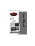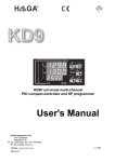
1
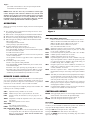
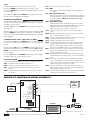
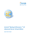
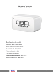
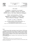
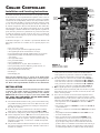
Chiller Controller
Holders for
Optional Fail
Safe Batteries
Installation and Servicing Instructions
The Chiller Controller has the most features of any Sporlan controller.
It will control one or two Sporlan Electric Expansion Valves, and controls superheat by means of pressure-temperature control. The controller
controls each valve independently, and the valves may be different sizes,
i.e. one SEI-2 and one SEH-175. Pressure-temperature superheat control
for one of four common refrigerants may be selected. Controllers can
be ordered configured for R-22, R-134a, R-404A, R-407C and R-507.
The refrigerant type can be changed in the field by use of the optional
“Panel Display.” Onboard readouts show actual superheat, superheat set
point, and valve position. Two push buttons are provided on the board,
to change the superheat set point, as well as open, close, or position the
valve. Proportional and Integral set points are also included to change
responsiveness of the valve.
Two 20 ampere
240 VAC
NC/NO relays
24 Volt AC
50/60 Hz.
40 VA Input
One 5 ampere
240 VAC
NC/NO relay
DI Pumpdown
Terminals
1- Pressure
1S Transducer
1+ Terminals
R
G Valve 1
Cable
W
Terminals
B
As illustrated in Figure 1, the controller is provided with hardware and
input/output connections for a number of user specified purposes. See
below:
• One or two valve control
• Two pressure inputs (transducer supplied by Sporlan)
• Two digital inputs (from external switches or relays)
• Four temperature inputs (Sporlan supplied surface or air sensors)
• Optional battery backup for onboard time clock and fail-safe
valve closure
• Two digit LED readout
• One green LED indicator
• One red LED indicator
• Two push buttons for set point, alarm cancellation, etc.
• One 8-position dip switch for addressing, mode selection, etc.
• Two 20 amp, 240 VAC NC/NO relays
• One 5 amp 240 VAC NC/NO relay
• RS 485 port
• Panel Display jack
Please note that although relays, etc. appear on the Chiller Board,
standard software does not support those devices. Custom (proprietary) software must be written for anything other than superheat control. Please contact Sporlan Division of Parker for more information.
INSTALLATION
When handling the boards, electrostatic protection procedures should
be followed. The installer should be grounded through a ground
strap. If ground straps or other ESD protection is not available,
ONLY handle the board by its edges or by the battery holders. DO
NOT TOUCH ANY COMPONENTS ON THE BOARD EXCEPT
THE BATTERY HOLDER AND RELAYS.
1. The board should be mounted in a dry, protected environment using
the predrilled mounting holes in each corner. Make sure none of the
printed circuit paths or components are touching the metal panel or
any thing else conductive.
2. If only one valve is used, connections are to be made to terminal
block closest to display readout and push buttons PB1 and PB2.
3. Controllers are configured for pressure temperature superheat control.
4. Connect temperature sensor to TS2. The sensor is not polarized. For
suction lines 7/8” or less, the sensor should be mounted to the copper suction line after the evaporator, using the furnished clamps. For
larger lines or steel piping, a “well sensor,” available from Sporlan,
should be installed.
5. The pressure transducer should be mounted on the top of the suction
line near the temperature sensor location. Transducer connections to
the board are as follows:
Two Digit
LED Display
Green
Status LED
Panel
Display
Jack
Figure 1
RS 485 Post
Red
Status
LED
PB1
PB2
TS2 Temperature
Sensor
TS1 Terminals
Two Push
Buttons
Terminals for Valve 1 shown.
Terminals for Valve 2 similar.
6.
7.
• The power wire is red and is connected to the 1+ terminal.
• The signal wire is green and is connected to the 1S terminal.
• The ground wire is black and is connected the 1- terminal.
The valve leads are connected to the terminals labeled Valve 1.
• The black lead is connected to terminal labeled B of Valve 1.
• The white lead is connected to terminal labeled W of Valve 1.
• The green lead is connected to terminal labeled G of Valve 1.
• The red lead is connected to terminal labeled R of Valve 1.
DI1 is a digital input used as a pumpdown terminal. A short or
closed contact from an external relay will close the valve for pumpdown. When the relay opens or the short is removed, the valve will
return to normal operation.
8. If two valves are used the second valve and its temperature sensor,
pressure transducer, and pumpdown are connected as above. Caution
should be used on two valve systems to make sure that the sensors are
connected to the terminal strip used for the valve they are controlling.
• The temperature sensor for Valve 2 is connected to TS4 as described above.
• The pressure transducer for Valve 2 is connected to 2+, 2S, 2- as described above.
• The valve is connected to terminals labeled Valve 2 as described
above.
• The pumpdown terminal for Valve 2 is labeled DI2. It is connected as described above.
• Power is connected to the terminal marked 24VAC. Power
requirements are 24 volts AC at 40 VA. For protection from
electrical transients, connect one MOV varistor between one
leg of the input voltage of the 24 VAC transformer and earth
ground. Connect a second MOV varistor between the other leg of
the input voltage of the 24 VAC transformer to earth ground. A
recommended part number for a MOV is Harris Semiconductor
Page 2
part number V150LA20A for 120 VAC input and part number
V275LA20A for 208/240 VAC input.
NOTE: Sensor and valve wires may be extended for remote applications. Waterproof butt connectors should be used, and the cable
should be at least 16 gauge. Care must be taken to ensure a good splice
and that the individual wires are correctly identified. For remote
installation where the sensors are located more than 25 ft. from the
controller, contact Sporlan Division of Parker for guidance.
OPERATION
When first powered up the numeric display will show actual superheat
for Circuit 1.
1. The controller may be toggled between settings for Circuit 1 and 2
by pressing PB1 (left button).
2. When Circuit 1 is being displayed, the small Green LED will be lit.
3. When Circuit 2 is being displayed, the small Red LED will be lit.
4. If Circuit 2 is not being used its display and setting will show “00”.
5. PB2 will toggle the readings as follows and the small Green LED
will be steady or flash:
• Actual Superheat, LED constant.
• Valve percentage open, LED slow flash.
6. To change superheat set point for Valve 1:
•Make sure the display shows the superheat of Valve 1.
•Press and hold PB1 and PB2 for 8 seconds, LED will flash rapidly.
•Use PB1 to increment set point.
•Use PB2 to decrement set point.
•Press and hold PB1 and PB2 for 5 seconds to lock in set point and return to actual superheat.
•To set superheat for Valve 2 toggle PB1 to Valve 2 superheat and repeat above.
7. To manually change valve position:
•Scroll to valve position reading with PB2.
•Press and hold PB1 and PB2 simultaneously for 8 seconds, Green LED will flash rapidly.
•Increment “valve open” percentage by pressing PB1 for 1 second.
•Decrement “valve open” percentage by pressing PB2 for 1 second.
Valve will maintain manual open position for 1 hour or until PB1 and PB2 are pressed simultaneously and held for 5 seconds.
REMOTE PANEL DISPLAY
A remote panel display is available that will allow access to all the parameters of the controller. The Remote Panel Display can be used as a set
point tool in production, a diagnostic tool in the field or as a permanent
readout device for the controller. A five-foot cable is included.
Plug the remote display into the telephone jack (J9) on the controller. The
following is a list of readings available:
Superheat read by controller for AC circuit 1
Number of steps valve is open (0-6386) for AC circuit 1
Pressure read by the transducer (0-153 psi gauge) for AC
circuit 1
TMP1 Temperature read by the temperature sensor (-50 to 103°F) for
AC circuit 1
TST1 Saturated temperature for AC circuit 1
AC1, PDN1
AC1 when in normal operation
PDN1 when in pumpdown for AC circuit 1
R22, 134A, 407C, 404A, 507
R22 for refrigerant R-22, 134A for refrigerant R-134a, 407C
for refrigerant R-407C, and 404A for refrigerant R-404A and
R507 for refrigerant R-507. Note: Not all controllers have
both R-507 and R-407C.
SUP1
POS1
PRS1
Figure 2
LGE1, SML1, MED1, ESX1, S251
LGE1 if the EEV used is an SEI-50 or larger for AC circuit 1.
SML1 if the EEV used is smaller than an SEI-25 for AC circuit 1.
MED1 if the EEV used is a SEI-25 for AC circuit 1.
ESX1 if the EEV used is a ESX for AC circuit 1.
S251 if the EEV is an SER 1.5 to 20.
SSP1 Superheat set point (0 to 16°F) for AC circuit 1. Default is 10°F.
MOP1 Maximum operating suction pressure set point (0 to 153 PSI)
for AC circuit 1. Default is 153 PSI.
CTS1 Cut out suction pressure set point for AC circuit 1 (0 to 153 PSI)
CLP1 Calibrate pressure transducer for AC circuit 1.
CLT1 Calibrate temperature sensor for AC circuit 1.
PRO1 Proportional gain set point for AC circuit 1. Number of steps per
degree that superheat is above or below the superheat set point
(5 to 255 steps per degree). Default is 45 for LGE1 setting, 22
for MED1 setting, and 11 for SML1 setting.
INT1 Integral set point for AC circuit 1. Number of seconds the controller waits to update the reference valve position. (1 to 120
seconds). Default is 10 seconds.
DER1 Derivative setpoint for valve 1. Advanced algorithm parameter
that determines the slope of the change control point. Default is
zero.
DON1 Time delay in seconds between end of pumpdown and compressor start when Relay 2 is used to pilot the compressor contactor.
The pre-opens the valve before compressor start to avoid nuisance low pressure safety trips. 2 seconds.
DOF1 Time in seconds that the valve is shut before the compressor
Relay 2 opens to stop the compressor. Allows refrigerant pumpdown/pumpout. Default is 2 seconds.
DST1 Used with DON1. Number of steps to pre-open the valve before
compressor start. Default varies with valve size.
CONTROLLER MENUS
ENTER will toggle display between one of the displays described above
and the numeric value read for that particular display.
UP will scroll through the menu from SUP1 to POS1, etc.
DOWN will scroll through the menu the opposite way.
POS1 MODE
Press and hold the UP button and ENTER button simultaneously for 5
seconds to put the controller in manual valve position. The number of
steps open will be displayed and the 1000’s digit will blink.
Pressing the UP button will open the valve 1000 steps.
Pressing the DOWN button will close the valve 1000 steps.
Pressing the ENTER button will change the flashing digit from 1000’s
digit to the 100’s digit.
Page 3
Pressing the UP button will open the valve 100 steps.
Pressing the DOWN button will close the valve 100 steps.
Pressing the ENTER button will change the flashing digit from 100’s digit
to the 10’s digit.
Pressing the UP button will open the valve 10 steps.
Pressing the DOWN button will close the valve 10 steps.
Pressing the ENTER button will change the flashing digit from 10’s digit
to the 1’s digit.
Pressing the UP button will open the valve 1 step.
Pressing the DOWN button will close the valve 1 step.
Pressing the ENTER button will change the flashing digit from 1’s digit
to the 1000’s digit.
Press and hold the UP button and ENTER button together for 5 seconds to
put the controller in normal control. The digits will stop blinking.
SSP1 MODE
Press and hold the UP button and ENTER button for 5 seconds to enable
the superheat set point to be changed. The set point is displayed and the
100’s digit will blink.
Pressing the UP button will increase the set point by 100 degrees.
Pressing the DOWN button will decrease the set point by 100 degrees.
Pressing the ENTER button will change the flashing digit from 100’s digit
to the 10’s digit.
Pressing the UP button will increase the set point by 10 degrees.
Pressing the DOWN button will decrease the set point by 10 degrees.
Pressing the ENTER button will change the flashing digit from 10’s digit
to the 1’s digit.
Pressing the UP button will increase the set point by 1 degree.
Pressing the DOWN button will decrease the set point by 1 degree.
Pressing the ENTER button will change the flashing digit from 1’s digit
to the 100’s digit.
Press and hold the UP button and ENTER button together for 5 seconds
to save the set point. The digits will stop blinking.
MOP1 MODE
Press and hold the UP button and ENTER button for 5 seconds to enable
the Maximum Operating suction Pressure set point to be changed. The set
point is displayed and the 100’s digit will blink.
Pressing the UP button will increase the set point by 100 PSI.
Pressing the DOWN button will decrease the set point by 100 PSI.
Pressing the ENTER button will change the flashing digit from 100’s digit
to the 10’s digit.
Pressing the UP button will increase the set point by 10 PSI.
Pressing the DOWN button will decrease the set point by 10 PSI.
Pressing the ENTER button will change the flashing digit from 10’s digit
to the 1’s digit.
Pressing the UP button will increase the set point by 1 PSI.
Pressing the DOWN button will decrease the set point by 1 PSI.
Pressing the ENTER button will change the flashing digit from 1’s digit
to the 100’s digit.
Press and hold the UP button and ENTER button for 5 seconds to save the
set point. The digits will stop blinking.
CTS1 MODE
Press and hold the UP button and ENTER button for 5 seconds to enable
the cut out suction pressure set point to be changed. The set point is displayed and the 100’s digit will blink.
Pressing the UP button will increase the set point by 100 PSI.
Pressing the DOWN button will decrease the set point by 100 PSI.
Pressing the ENTER button will change the flashing digit from 100’s digit
to the 10’s digit.
Pressing the UP button will increase the set point by 10 PSI.
Pressing the DOWN button will decrease the set point by 10 PSI.
Pressing the ENTER button will change the flashing digit from 10’s digit
to the 1’s digit.
Pressing the UP button will increase the set point by 1 PSI.
Pressing the DOWN button will decrease the set point by 1 PSI.
Pressing the ENTER button will change the flashing digit from 1’s digit
to the 100’s digit.
Press and hold the UP button and ENTER button for 5 seconds to save the
set point. The digits will stop blinking.
NOTE: CTS1 set point is used to help stop nuisance, low suction pressure
trips of the compressor. If the suction pressure goes below CST1, and the
superheat is above the superheat set point, the valve will keep opening
until the suction pressure is above CST1 or the superheat is below its set
point. The controller will start controlling superheat from this new valve
position. If the superheat is below its set point and the suction pressure
is below this set point, the controller will change CST1 to 12 PSI below
current suction pressure. If power is lost, the original saved set point is
used again.
When in CLP1 or CLT1, the numeric display shows the PSI or degrees to
be either added or subtracted from that particular sensor, depending if the
reading is negative or positive. Press and hold the UP button and ENTER
button for 5 seconds to enable the sensor to be calibrated.
The CAL number is displayed and the 10’s digit will blink.
Pressing the UP button will increase the CAL number by 10 PSI or degrees.
Pressing the DOWN button will decrease the CAL number by 10 PSI or
degrees.
Pressing the ENTER button will change the flashing digit from 10’s digit to
the 1’s digit.
Pressing the UP button will increase the CAL number by 1 PSI or degree.
Pressing the DOWN button will decrease the CAL number by 1 PSI or
degree.
Pressing the ENTER button will change the flashing digit from 1’s digit
to the 0.1’s digit.
Pressing the UP button will increase the CAL number by 0.2 PSI or degree.
Pressing the DOWN button will decrease the CAL number by 0.2 PSI
or degree.
Pressing the ENTER button will change the flashing digit from 0.1’s digit
to the 10’s digit.
Press and hold the UP button and ENTER button for 5 seconds to save the
CAL number. The digits will stop blinking.
PRO1, INT1, DER1, DON1, DOF1 AND DST1
SETTING PROCEDURE
Use the UP and DOWN buttons to scroll to the Setpoint to be changed.
Press and hold the UP button and ENTER button for 5 seconds to allow
set point to be changed. The set point is displayed and the 100’s digit will
blink.
Pressing the UP button will increase the set point by 100 units.
Pressing the DOWN button will decrease the set point by 100 units.
Pressing the ENTER button will change the flashing digit from 100’s digit
the 10’s digit.
Pressing the UP button will increase the set point by 10 units.
Pressing the DOWN button will decrease the set point by 10 units.
Pressing the ENTER button will change the flashing digit from 10’s digit
to the 1’s digit.
Page 4
Pressing the UP button will increase the set point by 1 unit.
Pressing the DOWN button will decrease the set point by 1 unit.
Pressing the ENTER button will change the flashing digit from 1’s digit
to the 100’s digit.
Press and hold the UP button and ENTER button together for 5 seconds to
save the set point. The digits will stop blinking.
CHANGING REFRIGERANTS
Press and hold the UP button and ENTER button simultaneously for 5
seconds to enable the controller to change to another type of refrigerant.
All 4 digits will start to blink.
Pressing the UP button or the DOWN button will change the display to
other refrigerants.
When the display shows the desired refrigerant, press and hold the UP
button and ENTER button for together 5 seconds. The controller will save
and use the selected refrigerant’s table for saturated temperature. The digits
will stop blinking.
CHANGING VALVE TYPES – LGE1, SML1, or MED1
Press and hold the UP button and ENTER button for 5 seconds to enable
the controller to change to the other type of valves. All 4 digits will start
to blink.
Pressing either the UP button or the DOWN button will change the display between the different valve types. Press and hold the UP button and
ENTER button together for 5 seconds to save the selection. The digits
will stop blinking.
Pressing the UP button and the DOWN button simultaneously will toggle
the display between AC circuit 1 and AC circuit 2.
AC CIRCUIT 2 MENU
The preceding instructions apply to AC circuit 2 as well as AC circuit 1:
SUP2
POS2
PRS2
TMP2
Superheat read by controller for AC circuit 2
Number of steps valve is open (0-6386) for AC circuit 2
Pressure read by the transducer (0-153 PSI, gauge) for AC
circuit 2
Temperature read by the temperature sensor (-50 to 103°F) for
AC circuit 2
TST2 Saturated temperature for AC circuit 2
AC2, PDN2
AC2 when in normal operation, PDN2 when in pumpdown for
AC circuit 2
R22, 134A, 407C, 404A, R507
R22 for refrigerant R-22, 134A for refrigerant R-134a, 407C for
refrigerant R-407C, and 404A for refrigerant R-404A and R507
for refrigerant R-507. Note: Not all controllers have both
R-507 and R-407C.
LGE2, SML2, MED2, ESX2
LGE2 if the EEV used is an SEI-50 or larger for AC circuit 2.
SML2 if the EEV used is smaller than an SEI-25 for AC circuit 2.
MED2 if the EEV used is a SEI-25 for AC circuit 2.
ESX2 if the EEV used is a ESX for AC circuit 2.
SSP2 Superheat set point (0 to 16°F) for AC circuit 2. Default is
10°F.
MOP2 Maximum operating suction pressure set point (0 to 153 PSI)
for AC circuit 2. Default is 153 PSI.
CTS2 Cut out suction pressure set point for AC circuit 2 (0 to 153 PSI)
CLP2 Calibrate pressure transducer for AC circuit 2
CLT2 Calibrate temperature sensor for AC circuit 2
PRO2 Proportional gain set point for AC circuit 2. Number of steps
per degree that superheat is above or below the superheat set
point (5 to 255 steps per degree). Default is 45 for the LGE2
setting, 22 for the MED2 setting, or 11 for the SML2 setting.
INT2 Integral set point for AC circuit 2. Number of seconds the controller waits to update the reference valve position. (1 to 120
seconds). Default is 10 seconds.
DER2 Derivative setpoint for valve 2. Advanced algorithm parameter
that determines the slope of the change control point. Default is
zero.
DON2 Time delay in seconds between end of pumpdown and compressor start when Relay 1 is used to pilot the compressor contactor. The pre-opens the valve before compressor start to avoid
nuisance low pressure safety trips. 2 seconds.
DOF2 Time in seconds that the valve is shut before the compressor
Relay 1 opens to stop the compressor. Allows refrigerant pumpdown/pumpout. Default is 2 seconds.
DST2 Used with DON2. Number of steps to pre-open the valve before
compressor start. Default varies with valve size.
CHILLER P/T CONTROLLER WIRING SCHEMATIC*
PB1
DI1
PB2
8.8.
Pressure
Transducer
Pumpdown
Relay
(optional)
TS2 B W G R 1+ 1S 1-
DI1
1- = Black
1S = Green
1+ = Red
R = Red
G = Green
W = White
B = Black
TS2 - Temp. Sensor 2
TS1 - Temp. Sensor 1
TS1
24 VAC
24 VAC
40 VA
Transformer
Valve 2 connections
on left block when used
Evaporator
SEI/SEH
Temperature
Sensor
*Only valve 1 shown, valve 2 connected in similarly.
© 2008 Sporlan Division, Parker Hannifin Corp., 206 Lange Drive, Washington, Missouri 63090
SD-252-408