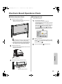
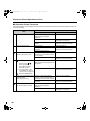
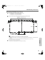
1
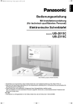
UB5838C-PJQXC0259ZA_mst.book 1 ページ
2009年5月26日 火曜日 午後2時59分
Operating Instructions
Electronic Board
Model No.
[Stand (option)]
[Wall-mounting]
UB-5838C
UB-5338C
The unit in this picture is UB-5838C.
(Stand kit is optional.)
Installation Manual Included (for qualified service personnel)
• To assemble this unit, please refer to the Installation manual on page 38 through 55.
• Before operating this unit, please read these instructions completely and keep them carefully for future reference.
• This unit is designed for installation by a qualified servicing dealer.
Installation performed by non-authorized individuals could cause safety-related problems with the operation of this
equipment.
For U.S.A. only:
• To locate the closest authorized dealer in your area, please call 1-800-449-8989.
UB5838C-PJQXC0259ZA_mst.book 2 ページ
2009年5月26日 火曜日 午後2時59分
Thank you for purchasing the Panasonic Electronic Board.
For optimum performance and safety, please read these instructions carefully.
Accessories
Check that all of the following items are included with the unit. In the event that an item is missing, please contact
your dealer.
Q’ty
• Markers (Black, Red, Blue) . . . . . . . . . . . 1 each
• Eraser . . . . . . . . . . . . . . . . . . . . . . . . . . . . . . . .1
• Power cord . . . . . . . . . . . . . . . . . . . . . . . . . . . . .1
*1 For
Q’ty
• USB cable . . . . . . . . . . . . . . . . . . . . . . . . . . . . . 1
• Operating Instructions . . . . . . . . . . . . . . . . . . . 1
• Warranty card*1 . . . . . . . . . . . . . . . . . . . . . . . . . 1
U.S.A. models only.
For information on separately available items, refer to page 37.
Note
• UB-5838C is a wide-size model.
UB-5338C is a standard-size model.
• These operating instructions are based on the UB-5838C.
Things you should keep a record of
Attach your sales receipt here
For your future reference
Date of purchase: _________________________
Serial number: ___________________________
Dealer’s name and address: _____________________________________________________________
Tel:
Warning about saving data
When the system storage device or any of its optional storage device is adversely effected by operational
errors, static electricity, electrical noise, vibration, dust or when the power has been cut off due to malfunction,
repair or inadvertently, the memory contents may be lost or changed. Before operating the system, make a point
of reading the precautionary notes in the Operating Instructions and the help information, and observe them
during operation.
Please observe carefully the following precaution:
• Make absolutely sure that all important data is saved by back-up or the original is saved.
The manufacturer hereby declares that it cannot be held accountable for any loss or change in any data stored
on floppy disks, hard disks, optical disks, or other memory devices.
2
UB5838C-PJQXC0259ZA_mst.book 3 ページ
2009年5月26日 火曜日 午後2時59分
Federal Communications Commission Requirements
(For United States only)
Note:
This equipment has been tested and found to comply with the limits for a Class A digital device, pursuant
to part 15 of the FCC Rules. These limits are designed to provide reasonable protection against harmful
interference when the equipment is operated in a commercial environment. This equipment generates,
uses, and can radiate radio frequency energy and, if not installed and used in accordance with the
instruction manual, may cause harmful interference to radio communications. Operation of this equipment
in a residential area is likely to cause harmful interference in which case the user will be required to correct
the interference at his own expense.
FCC Warning:
To assure continued FCC compliance, the user must use only the provided power supply cord.
Also, any unauthorized changes or modifications to this equipment would void the user’s
authority to operate this device.
3
UB5838C-PJQXC0259ZA_mst.book 4 ページ
2009年5月26日 火曜日 午後2時59分
Illegal Duplication
It is unlawful to make duplication of certain documents.
Duplicating certain documents may be illegal in your country.
Penalties of fines and/or imprisonment may be imposed on those found guilty. The following are examples of
items that may be illegal to duplicate in your country.
• Currency
• Bank notes and checks
• Bank and government bonds, and securities
• Passports, licenses, official or private documents, identification cards, and the like
• Copyright materials, or trademarks without the consent of the owner
• Postage stamps, and other negotiable instruments
This list is not inclusive, and no liability is assumed for either its completeness or accuracy.
In case of doubt, contact your legal counsel.
Notice:
Install your machine near a supervised area to prevent illegal duplication from being made.
4
UB5838C-PJQXC0259ZA_mst.book 5 ページ
2009年5月26日 火曜日 午後2時59分
Trademarks
• Microsoft, Windows and Windows Vista are either registered trademarks or trademarks of Microsoft
Corporation in the United States and/or other countries.
• IBM and AT are trademarks of International Business Machines Corporation in the United States, other
countries, or both.
• SD Logo is a trademark.
• All trademarks referred to in this manual are property of their respective companies.
• This software is based in part of the work of the IndependentJPEG Group.
• This software is based on the “libtiff” which has the following copyrights:
Copyright (C) 1988–1997 Sam Leffler
Copyright (C) 1991–1997 Silicon Graphics, Inc.
The information given in this Operating Instructions is subject to change without notice.
Exemption of Liability
Panasonic Communications Co., Ltd. is not responsible for accidents or injuries caused by, but not limited to, the
following:
1. Altering the device or improper installation construction.
2. Using the device for purposes beyond its intended use.
3. Earthquake, fire, flood, tidal wave, hurricane, lightning or other natural phenomena.
4. Natural aging of the building or similar phenomena.
5
UB5838C-PJQXC0259ZA_mst.book 6 ページ
2009年5月26日 火曜日 午後2時59分
Features
The UB-5838C / UB-5338C is a color electronic board. It is possible to output scanned hand-written text/diagrams as
follows:
■ Storing on a USB Flash Memory Device
Allows scanned hand-written text/diagrams to be stored onto a USB flash memory device.*1
*1 Not
all USB flash memory devices are compatible with this unit.
■ Storing on an SD Memory Card
Allows scanned hand-written text/diagrams to be stored onto an SD memory card.*2
*2 SDHC
memory card is not supported. Not all SD memory cards are compatible with this unit.
■ Printing with an External Printer
Allows scanned hand-written text/diagrams to be printed with an external printer via USB cable.
■ Computer Interfacing
The USB Mass Storage Device allows you to copy scanned hand-written text/diagrams when a computer is
connected. It is not necessary to install special drivers or software to your computer.
It is possible to save a maximum of 2 scanned images to the electronic board.
Note
• For information regarding available USB flash memory devices, SD memory cards, and printers, refer to the
following site:
http://panasonic.co.jp/pcc/products/en/eboard/ub-5838c_info.htm
6
UB5838C-PJQXC0259ZA_mst.book 7 ページ
2009年5月26日 火曜日 午後2時59分
Table of Contents
Before You Start
Page
Before You Start
For Your Safety . . . . . . . . . . . . . . . . . . . . . . . . . . . . . . . . . . . . . . . . . 8
Precautions . . . . . . . . . . . . . . . . . . . . . . . . . . . . . . . . . . . . . . . . . . . 12
Part Names and Functions . . . . . . . . . . . . . . . . . . . . . . . . . . . . . . 14
• Control Panel . . . . . . . . . . . . . . . . . . . . . . . . . . . . . . . . . . . . . . . . . . . . . . . . . . 15
Using
•
•
•
•
Using
Before Using . . . . . . . . . . . . . . . . . . . . . . . . . . . . . . . . . . . . . . . . . . 16
Scanning . . . . . . . . . . . . . . . . . . . . . . . . . . . . . . . . . . . . . . . . . . . . . 17
Storing images on a USB flash memory device . . . . . . . . . . . . . . . . . . . . . . . . 18
Storing images on an SD memory card . . . . . . . . . . . . . . . . . . . . . . . . . . . . . . 19
Printing with an external printer . . . . . . . . . . . . . . . . . . . . . . . . . . . . . . . . . . . . 20
Scanning to a computer . . . . . . . . . . . . . . . . . . . . . . . . . . . . . . . . . . . . . . . . . . 21
Moving the Electronic Board. . . . . . . . . . . . . . . . . . . . . . . . . . . . . 23
Setting the Unit . . . . . . . . . . . . . . . . . . . . . . . . . . . . . . . . . . . . . . . . 24
Setting the number of copies . . . . . . . . . . . . . . . . . . . . . . . . . . . . . . . . . . . . . . 24
Setting for scanning time display . . . . . . . . . . . . . . . . . . . . . . . . . . . . . . . . . . . 24
File format set-up . . . . . . . . . . . . . . . . . . . . . . . . . . . . . . . . . . . . . . . . . . . . . . . 25
Setting for Full Size Scanning (UB-5838C only) . . . . . . . . . . . . . . . . . . . . . . . 26
Setting the current time . . . . . . . . . . . . . . . . . . . . . . . . . . . . . . . . . . . . . . . . . . 26
Setting the Password . . . . . . . . . . . . . . . . . . . . . . . . . . . . . . . . . . . . . . . . . . . . 27
Testing the Printer . . . . . . . . . . . . . . . . . . . . . . . . . . . . . . . . . . . . . . . . . . . . . . 28
Help
•
•
•
•
•
•
•
Help
Daily Care and Maintenance . . . . . . . . . . . . . . . . . . . . . . . . . . . . . 29
• Cleaning the Screen and the Unit . . . . . . . . . . . . . . . . . . . . . . . . . . . . . . . . . . 29
• Caring for the Eraser . . . . . . . . . . . . . . . . . . . . . . . . . . . . . . . . . . . . . . . . . . . . 29
• Replacing the Battery for the unit clock . . . . . . . . . . . . . . . . . . . . . . . . . . . . . . 30
Troubleshooting . . . . . . . . . . . . . . . . . . . . . . . . . . . . . . . . . . . . . . . 31
Installation
• Error Codes . . . . . . . . . . . . . . . . . . . . . . . . . . . . . . . . . . . . . . . . . . . . . . . . . . . 33
Specifications . . . . . . . . . . . . . . . . . . . . . . . . . . . . . . . . . . . . . . . . . 36
• Separately Available Items. . . . . . . . . . . . . . . . . . . . . . . . . . . . . . . . . . . . . . . . 37
Installation
Installation Manual . . . . . . . . . . . . . . . . . . . . . . . . . . . . . . . . . . . . . 38
7
UB5838C-PJQXC0259ZA_mst.book 8 ページ
2009年5月26日 火曜日 午後2時59分
For Your Safety
To prevent severe injury and loss of life, read this
section carefully before using the unit to ensure proper
and safe operation of your unit.
WARNING
CLASS 1 LED PRODUCT
The following graphic symbols are used in this
Operating Instructions manual.
Power and Ground Connection
WARNING
Denotes a potential
hazard that could
result in serious
injury or death.
The power source voltage of this unit is listed
on the nameplate. Only plug the unit into an
AC outlet with the proper voltage.
If you use a cord with an unspecified current
rating, the unit or plug may emit smoke or
become hot to the touch.
CAUTION
Denotes hazards
that could result in
minor injury or
damage to the unit.
When you operate this product, the power
outlet should be near the product and easily
accessible.
These symbols are used to
alert operators to a specific
operating procedure that
must not be performed.
These symbols are used to
alert operators to a specific
operating procedure that
must be emphasized in order
to operate the unit safely.
To ensure safe operation the power cord
supplied must be inserted into a standard
three-prong AC outlet which is effectively
grounded (earthed) through the normal
wiring.
The fact that the equipment operates
satisfactorily does not imply that the power
point is grounded (earthed) and that the
installation is completely safe. For your
safety, if in any doubt about the effective
grounding (earthing) of the power point,
consult a qualified electrician.
If the plug cannot be inserted into the AC
outlet, contact a licensed electrician to
replace the AC outlet with a properly
grounded (earthed) one.
Do not defeat the grounding (earthing) plug
(ex. do not use a conversion plug).
Plug the power cord firmly into an AC outlet.
Otherwise, it can cause fire or electric shock.
Do not pull, bend, rest objects on, or chafe
the power cord and plug. Damage to the
power cord or plug can cause fire or electric
shock.
8
UB5838C-PJQXC0259ZA_mst.book 9 ページ
2009年5月26日 火曜日 午後2時59分
For Your Safety
Ensure that the plug connection is free of
dust. In a damp environment, a
contaminated connector can draw a
significant amount of current that can
generate heat and eventually cause fire if left
unattended over an extended period of time.
Never touch the plug with wet hands.
Danger of electric shock exists.
Stop operation immediately if the unit emits
smoke, excessive heat, abnormal smell or
unusual noise. These conditions can cause
fire or electric shock. Immediately turn the
unit off and unplug the power cord, and
contact your dealer for service.
When disconnecting the unit, grasp the plug
instead of the cord. Pulling on a cord forcibly
can damage it and cause fire or electric
shock.
During thunderstorms, do not touch the
unit and plug. It may cause an electric
shock.
Installation and Relocation
When the unit will no longer be used, in order
to prevent it from falling, do not leave the unit
installed, but remove it. If the unit falls, it can
cause injury.
Operating Safeguards
Before You Start
Do not attempt to repair the power cord or
plug. If the power cord or plug is damaged or
frayed, contact an authorized service
representative for a replacement.
If metal fragments or water gets into the unit,
turn the unit off and unplug the unit
immediately. Contact your dealer for service.
Operating the contaminated unit can cause
fire or electric shock.
Never open or remove unit covers that are
screwed with screws unless specifically
instructed in the “Operating Instructions”. A
high-voltage component can cause electric
shock.
Do not alter the unit or modify any parts.
Alteration or modification can cause fire or
electric shock.
CHOKING HAZARD
Keep the marker’s cap, battery, SD memory
card or USB flash memory device out of
reach of children to prevent chocking.
Battery
Use only the specified type of battery. Using
the incorrect type of battery can result in
overheating/burning or leakage of battery
acid.
Make sure that the battery is installed with
the correct polarity as indicated on the
battery holder. Incorrectly installed batteries
may burst or leak, resulting in injuries.
Batteries that seem worn down or damaged
should not be used. Using worn down or
damaged batteries may result in leaking.
Do not charge, short, heat, break or throw in
a fire, as it may result in the battery leaking,
generating heat, or bursting.
When disposing of the battery, cover the
battery contacts with insulation (ex. tape).
Direct contact with other batteries may result
in leaking, fire, or explosion.
Do not solder the battery, as it may result in
the battery leaking, generating heat, or
bursting.
9
UB5838C-PJQXC0259ZA_mst.book 10 ページ
2009年5月26日 火曜日 午後2時59分
For Your Safety
CAUTION
After installing or moving the unit, lock the
casters and set the fall-prevention extension
legs.
Power
When the unit is not used over an extended
period of time, switch it Off and unplug it. If
an unused unit is left connected to a power
source for a long period, degraded insulation
may cause electric shock, current leakage or
fire.
The unit should be used only with the power
cord that is supplied by the manufacturer.
Installation and Relocation
Do not position the unit in a location where it
is unstable.
Do not place the unit in a hot humid or dusty
environment.
Prolonged exposure to these adverse
conditions may cause fire or electric shock.
To prevent fire or shock hazard, do not
expose this unit to rain or any type of
moisture.
When moving the unit, be sure to unplug the
power cord from the AC outlet. If the unit is
moved with the power cord attached, it can
cause damage to the cord which could result
in fire or electric shock.
Do not install the unit except by a qualified
service personnel.
10
Locking the casters
(Push this side)
Push to lock
Move this unit with two persons. Otherwise,
this unit may fall down and cause injury.
Operating Safeguards
If the unit is fallen down or damaged, turn the
unit off and unplug the power cord.
Otherwise, it may cause fire or electric
shock.
Do not put drinks, other liquids or heavy
items on the tray or screen. Accidental
spillage of liquid into the unit may cause
severe damage. If this occurs, turn the unit
off, unplug the power cord and contact your
dealer for service.
Do not lean against the screen or on the tray,
even if the unit is mounted on the wall.
Battery
When the unit is not used over an extended
period of time, take the batteries out of the
unit. Otherwise, the batteries may leak. Do
not use the leaked batteries.
UB5838C-PJQXC0259ZA_mst.book 11 ページ
2009年5月26日 火曜日 午後2時59分
For Your Safety
This appliance is supplied with a moulded three pin
mains plug for your safety and convenience.
A 5 amp. fuse is fitted in this plug. Should the fuse need
to be replaced please ensure that the replacement fuse
has a rating of 5 amps. and that it is approved by ASTA
or BSI to BS1362. Check for the ASTA mark
or the
BSI mark
on the body of the fuse. If the plug
contains a removable fuse cover, you must ensure that
it is refitted when the fuse is replaced. If you lose the
fuse cover the plug must not be used until a
replacement cover is obtained. A replacement fuse
cover can be purchased from your local Panasonic
Dealer.
Before You Start
Safety Information
(For United Kingdom only)
How to replace the fuse:
Open the fuse
compartment with a
screwdriver and replace
the fuse and fuse cover.
IF THE FITTED MOULDED PLUG IS UNSUITABLE
FOR THE SOCKET OUTLET IN YOUR PREMISES,
THEN THE FUSE SHOULD BE REMOVED AND THE
PLUG CUT OFF AND DISPOSED OF SAFELY.
THERE IS A DANGER OF SEVERE ELECTRICAL
SHOCK IF THE CUT OFF PLUG IS INSERTED INTO
ANY 13 AMP. SOCKET.
If a new plug is to be fitted please observe the wiring
code as shown below. If in any doubt please consult a
qualified electrician.
WARNING
This appliance must be earthed.
IMPORTANT
The wires in this mains lead are coloured as
follows:
Green-and-Yellow:
Earth
Blue:
Neutral
Brown:
Live
As the colours of the wire in the mains lead of this
apparatus may not correspond with the coloured
markings identifying the terminals in your plug, proceed
as follows.
The wire that is coloured GREEN-AND-YELLOW must
be connected to the terminal in the plug which is
marked with the letter E or by the Earth symbol
or
coloured GREEN or GREEN-AND-YELLOW.
The wire that is coloured BLUE must be connected to
the terminal in the plug that is marked with the letter N
or coloured BLACK.
The wire that is coloured BROWN must be connected
to the terminal in the plug which is marked with the
letter L or coloured RED.
11
UB5838C-PJQXC0259ZA_mst.book 12 ページ
2009年5月26日 火曜日 午後2時59分
Precautions
12
Installation
• Do not install the unit where it may be exposed to direct sunlight, near heating equipment,
or near air-conditioning vents as this may cause discoloration of the screen.
• Do not install the unit in strong sunlight or strong lighting. Proper copying may become
impossible.
• Do not install the unit in locations where the temperature may drop below 10°C (50°F) or
may change suddenly as this may disable the unit’s ability to make copies.
Screen Film
• Make thick and dark lines inside the
Approx. 20 mm (25/32")
scannable area. Note that any writing
inside the shaded area (on right) cannot
Approx.
Approx.
Scannable
be scanned.
20 mm
20 mm
area
(25/32")
(25/32")
• Do not allow writing to remain on the
screen for an extended period of time as
Approx. 20 mm (25/32")
it will become harder to erase.
• Do not erase with an overly dirty eraser
(see page 29).
• Periodically wipe the screen gently with a water-dampened cloth that has been thoroughly
wrung. (See page 29.)
• Use a commercially available white board cleaner for hard-to-erase stains.
• Do not touch the screen, write with markers, or erase while the screen is moving as this
may result in damage to the unit.
• Do not attach chart paper to the screen film for copying as this may result in damage to the
unit.
Markers and
Eraser
• Use only the included or designated markers and eraser. (See page 37.)
Use of accessories other than those included or designated may damage the screen
or result in hard-to-erase markings.
• Store markers horizontally as vertical storage may stop the ink from coming out.
Power Switch
• When turn the power switch on after turning off, wait 2 seconds or more.
Power Cord/
USB
• The included power cord is for use with this unit only. Do not use it with other devices.
• When moving the unit, disconnect the power cord and the USB cable from the electronic
board to prevent them from being damaged if stepped on or if they catch on something.
• Do not connect a USB flash memory device to “USB Connector-A for Printer”.
• Do not connect an external printer to “USB Connector-A for USB Flash Memory Device”.
• The use of a USB hub is not recommended. We cannot guarantee that the unit will work
properly.
• Do not connect two or more Panasonic electronic boards to a computer. It may cause the
computer operation to become unstable.
UB5838C-PJQXC0259ZA_mst.book 13 ページ
2009年5月26日 火曜日 午後2時59分
Precautions
Before You Start
Battery
If a battery is used improperly, the battery may leak, causing corrosion of the unit, or it may
burst. To prevent this, always follow the precautions given below.
• Always insert battery with its polarity properly oriented.
• If the battery has run out, remove it immediately and dispose of it according to local
regulations.
Leaving drained battery may result in leakage.
• Do not disassemble battery or place it in a fire.
• Do not short battery.
For U.S.A
This product contains a CR Coin Cell Lithium Battery which contains
Perchlorate Material - special handling may apply.
See www.dtsc.ca.gov/hazardouswaste/perchlorate
For Brazil
Após o uso as pilhas / baterias contidas neste produto
poderão ser dispostas em lixo doméstico.
For Netherlands
Bij dit produkt zijn batterijen geleverd.
Wanneer deze leeg ziju, moet u ze niet
weggooien maar inleveren als KCA.
For Taiwan ( 台灣 )
Please take the following precautions regarding the deletion of classified data, when discarding the
memory device (i.e., USB flash memory device or SD memory card) or giving the memory device to
another person.
Using basic operations such as “format” or “delete” on a computer may not completely erase the data from the
memory device.
To guarantee that the data you wish to erase will no longer exist, we recommend that you physically destroy the
memory device or use a file deleting software to erase the data.
The data that is stored on a memory device is the sole responsibility of you, the customer.
13
UB5838C-PJQXC0259ZA_mst.book 14 ページ
2009年5月26日 火曜日 午後2時59分
Part Names and Functions
Screen Film
Frame
Tray
Scanner
Stand
Control Box
Fall-prevention
Extension Leg
Fall-prevention
Extension Leg
Stand
Caster
with Lock
Caster
Caster with Lock
Caster
Control Panel
USB Connector-A
for Printer
USB Connector-A
for USB Flash
Memory Device
Power Cord
Battery Holder
Power Switch
AC Inlet
ON
OFF
SD Memory
Card Slot
SD Memory Card Cover
14
USB Connector-B
for Computer
UB5838C-PJQXC0259ZA_mst.book 15 ページ
2009年5月26日 火曜日 午後2時59分
Part Names and Functions
Before You Start
Control Panel
Mode Key
Display
Advance Key
Set-up Key
Name
Start/Stop Key
Description
When in standby mode, the display shows the current status of the unit as follows:
• The time is shown on the top left corner of the display.
• The scanning mode is shown on the icons on the left side of the display.
• The destination for scanned images is shown in the center of the display.
Display
Press repeatedly to select the scanning mode. The selected mode will be indicated
next to the icons on the left side of the display.
Mode Key
Color:
For scanning color images.
B/W:
For scanning black and white images.
Preview mode:
Set-up mode:
Returns to the previous screen.
Returns to standby mode.
Press to change the basic settings of this unit. (See page 24.)
Set-up Key
Preview mode:
Set-up mode:
Shows to the lower part.
Goes to the item below.
Press to advance the screen from right to left.
Advance Key
Preview mode:
Set-up mode:
Shows to the right part.
Goes to the next item to the right, or perform the item.
Press to start or stop scanning.
Start/Stop Key
15
UB5838C-PJQXC0259ZA_mst.book 16 ページ
2009年5月26日 火曜日 午後2時59分
Before Using
This unit has the following functions concerning
information security. Please use them properly.
■ Screen Erase Announce function
■ Operation Password function
After scanning the screen, the following display appears
to prompt you to erase the text/diagrams on the screen.
It is possible to set a password in order to prevent a
third party from operating the electronic board when the
power turns on or after a certain period of time has
passed.
For information on setting the password, refer to page
27.
The following display appears in the password input
display. Press the Mode Key (
), the Set-up Key
(
) or the Advance Key (
) and enter the
4-digit password.
When this display appears, erase the written text/
diagrams in order to prevent a third party from seeing
the screen before the written text/diagrams are erased.
Press the Mode Key (
) to cancel this display.
Note
• If this unit is not operated for about 5 minutes, the
screen saver function is activated to prevent burn in,
and the following display appears:
Note
• Do not forget the Password.
If you forget the Password, call your dealer.
Press any key to cancel this display.
16
UB5838C-PJQXC0259ZA_mst.book 17 ページ
2009年5月26日 火曜日 午後2時59分
Scanning
It is possible to output scanned images to a USB flash
memory device, SD memory card, external printer, or
computer.
If multiple output devices are connected to this unit at
the same time, the output destination will be selected in
the following priority:
1. Computer
2. USB flash memory device
3. SD memory card
4. External printer
The current destination is shown on the display.
• For information regarding available USB flash
memory devices, SD memory cards, and printers,
refer to the following site:
http://panasonic.co.jp/pcc/products/en/eboard/
ub-5838c_info.htm
• When the power switch is set to on ( I ) while the
screen is not set to the home position, the screen will
move to home position and stop.
• To scan the reverse side of the screen, press the
Advance Key
to send the screen film, before
proceeding to scan.
Note
Using
• Do not install the unit in places subject to direct
sunlight or strong lighting. Scanned images may
appear blank or darkened.
• When there is no appropriate output destination
connected to the unit, an electronic board icon is
shown on the display. In this case, the unit will not
start scanning even if you press the Start/Stop Key.
• When the output destination is a USB flash memory
device, an SD memory card, or a computer, the
following file formats can be selected (refer to “File
format set-up” on page 25).
Color:
PDF/JPEG format
B/W:
PDF/JPEG format
• Images output to a USB flash memory device or an
SD memory card are saved in following folder:
[Folder]
For UB-5838C: “UB-5838C”
For UB-5338C: “UB-5338C”
• Images output to a USB flash memory device, an SD
memory card, or a computer are saved as following
name:
[File name]
MMDDHHxx.pdf (in the case of PDF file)
Sequential number (00-99)
Hour
Day
Month
[File Extension]
PDF file:
“MMDDHHxx.pdf”
JPEG file: “MMDDHHxx.jpg”
17
UB5838C-PJQXC0259ZA_mst.book 18 ページ
2009年5月26日 火曜日 午後2時59分
Scanning
• When scanning has finished, a preview of the
scanned image is shown on the display.
Storing images on a USB flash
memory device
1
2
Set the power switch to on ( I ).
Connect the USB flash memory device to “USB
Connector-A for USB Flash Memory Device”.
Note
• Do not remove the USB flash memory device
until the preview is shown on the display.
5
• When the USB flash memory device is
connected, a USB flash memory icon will blink
on the display. Once the unit recognizes the
device, the icon will stop blinking.
The display below is an example of the unit in
standby mode.
Note
• You cannot use a USB flash memory device
that is equipped with certain features such as
a security feature.
18
3
Press the Mode Key
scanning mode.
4
Press the Start/Stop Key.
to select the
• The unit starts scanning.
• The scanning status is shown on the display.
Press the Advance Key (
image.
) to zoom in on the
• It is possible to view specific areas of the
image.
• The current view area is shown on the top left
side of the display.
Press the Set-up Key ( ) to move down.
Press the Advance Key ( ) to move left.
• Press the Mode Key (
) to return to the
preview.
6
Press the Mode Key (
).
7
After erasing the written text/diagrams on the
screen, press the Mode Key (
) to return to
standby mode.
• The Screen Erase Announce is shown on the
display.
• Only remove the USB flash memory device
once you have returned to standby mode.
• For information on saving files on a USB flash
memory device, refer to page 17.
UB5838C-PJQXC0259ZA_mst.book 19 ページ
2009年5月26日 火曜日 午後2時59分
Scanning
Storing images on an SD
memory card
1
2
3
Press the Mode Key
scanning mode.
4
Press the Start/Stop Key.
Set the power switch to on ( I ).
to select the
• The unit starts scanning.
• The scanning status is shown on the display.
Open the SD memory card cover and insert the
SD memory card into the SD memory card slot
until it is locked. Then close the SD memory
card cover.
• The SD memory card icon is shown on the
display.
The display below is an example of the unit in
standby mode.
Note
• Do not remove the SD memory card until the
preview is shown on the display.
5
Note
• SDHC memory card is not supported.
• If an SD memory card has been formatted
(ex. by the general formatting software of a
computer), it oftentimes cannot be recognized
by this unit.
To use the SD memory card with this unit, it
must be reformatted to comply with SD
memory card specifications using the
appropriate formatting software.
You can also download the formatting
software for the SD memory card from the
following site:
http://panasonic.jp/support/global/cs/sd/
download/sd_formatter.html
Using
• When scanning has finished, a preview of the
scanned image is shown on the display.
Press the Advance Key (
image.
) to zoom in on the
• It is possible to view specific areas of the
image.
• The current view area is shown on the top left
side of the display.
Press the Set-up Key ( ) to move down.
Press the Advance Key ( ) to move left.
• Press the Mode Key (
) to return to the
preview.
19
UB5838C-PJQXC0259ZA_mst.book 20 ページ
2009年5月26日 火曜日 午後2時59分
Scanning
6
Press the Mode Key (
).
7
After erasing the written text/diagrams on the
screen, press the Mode Key (
) to return to
standby mode.
• The Screen Erase Announce is shown on the
display.
• Only remove the SD memory card once you
have returned to standby mode.
• To remove the SD memory card, open the SD
memory card cover and unlock the SD
memory card by pressing it once. Once it is
unlocked you may remove it.
• For information on saving files on an SD
memory card, refer to page 17.
Printing with an external
printer
1
2
3
Set the power switch to on ( I ).
Turn the external printer on and load the paper.
Connect the external printer to “USB
Connector-A for Printer” with a USB cable.
Printer
• The printer icon is shown on the display.
The display below is an example of the unit in
standby mode.
4
Press the Mode Key
scanning mode.
to select the
5
When making multiple copies, press the Set-up
Key
, then press the Advance Key ( )
repeatedly to select the desired number of
copies (1 to 9).
• For details on making multiple copies, refer to
page 24.
20
UB5838C-PJQXC0259ZA_mst.book 21 ページ
2009年5月26日 火曜日 午後2時59分
Scanning
6
Press the Start/Stop Key.
• The unit starts scanning and the image is
printed.
• The copying status is shown on the display.
Scanning to a computer
■ System Requirements
Computer
IBM® PC/AT® or compatible machine
Interface
USB 2.0 or USB 1.1*1
OS
Windows® 2000*2
(Service Pack 4 or later)
Windows® XP*3
(Service Pack 2 or later)
Windows Vista®*4
• After printing is finished, the Screen Erase
Announce will be shown on the display.
*1 This
Note
• Only remove the USB cable once you have
returned to standby mode.
• For information regarding how to set ink
cartridges or paper in your printer, please
refer to the manual of the printer.
unit does not function with Hi-Speed USB 2.0. Even if
using a computer equipped with Hi-Speed USB 2.0, this unit
functions with Full Speed USB 2.0.
(This unit will not run at the rated speed of Hi-Speed
USB 2.0.)
*2 Microsoft® Windows® 2000 operating system (hereafter
Windows 2000)
*3 Microsoft® Windows® XP operating system
(hereafter Windows XP)
*4 Microsoft® Windows Vista® operating system
(hereafter Windows Vista)
Using
7
After erasing the written text/diagrams on the
screen, press the Mode Key (
) to return to
standby mode.
■ Scanning to a computer
1
2
Set the power switch to on ( I ).
Connect the computer to “USB Connector-B for
Computer” with a USB cable (included).
Computer
• The computer icon is shown on the display.
The display below is an example of the unit in
standby mode.
• The computer recognizes the electronic board
as a Removable Disk and the drive is
displayed in the Windows Explorer window.
21
UB5838C-PJQXC0259ZA_mst.book 22 ページ
2009年5月26日 火曜日 午後2時59分
Scanning
Note
• The use of a USB hub is not recommended.
We cannot guarantee that the unit will work
properly.
• Do not connect two or more Panasonic
electronic boards to a computer. It may cause
the computer operation to become unstable.
3
Press the Mode Key
scanning mode.
4
Press the Start/Stop Key.
Open the Removable Disk displayed on the
computer screen, and click [Refresh] from the
[View] in the Windows Explorer window.
• The scanned image file is shown on the
display.
Copy the image file in the Removable Disk onto
the computer’s desktop or into a folder.
Note
• It is possible to save a maximum of 2 scanned
images to the electronic board’s removable
disk.
If a third image file is scanned with the
electronic board, the first image file will be
deleted.
• The scanned image files will be deleted if the
USB cable is removed.
22
• It is possible to view specific areas of the
image.
• The current view area is shown on the top left
side of the display.
Press the Set-up Key ( ) to move down.
Press the Advance Key ( ) to move left.
• Press the Mode Key (
) to return to the
preview.
• The unit starts scanning.
• The scanning status is shown on the display.
Note
• Do not remove the USB cable until the
scanned image file has been completed
copied to the computer.
6
Press the Advance Key ( ) to zoom in on the
image with the electronic board.
to select the
• When scanning has finished, a preview of the
scanned image is shown on the display.
5
7
8
Press the Mode Key (
).
9
After erasing the written text/diagrams on the
screen, press the Mode Key (
) to return to
standby mode.
• The Screen Erase Announce is shown on the
display.
• Only remove the USB cable once you have
returned to standby mode.
Perform the following steps when removing
the USB cable:
1) Right-click the [Safely Remove Hardware]
icon in the taskbar notification area in the
bottom-right corner of the display.
(In Windows 2000, the icon is entitled
[Unplug or Eject Hardware].)
2) When the list of devices is displayed, click
the device to remove, and then click the
[Stop] button.
3) Remove the USB cable connected to the
computer from the electronic board.
• For information on saving files on a computer,
refer to page 17.
UB5838C-PJQXC0259ZA_mst.book 23 ページ
2009年5月26日 火曜日 午後2時59分
Moving the Electronic Board
1
Make sure that the power switch is set to off
( ), and disconnect the power cord on both
ends.
• Make sure if there are any other devices
connected to the unit. If so, disconnect them.
2
Release the lock A and fold back the fallprevention extension legs B as follows:
A
A
B
Using
3
Release the caster locks and move the unit.
Releasing the lock
Note
• Always move the unit with 2 people.
4
Lock the casters and set the fall-prevention
extension legs.
Locking the casters
(Push this side)
Push to lock
5
Plug-in the power cord on both ends.
23
UB5838C-PJQXC0259ZA_mst.book 24 ページ
2009年5月26日 火曜日 午後2時59分
Setting the Unit
The following settings can be made using the control
panel.
Note
• The item “Setting the number of copies” is displayed
at the top of the set-up menu only when the printer is
connected.
Setting for scanning time
display
It is possible to select whether the time that an image is
scanned is displayed on the image.
䎓䎗䎒䎓䎔䎒䎕䎓䎓䎜䎃䎔䎕䎝䎖䎗
Setting the number of copies
It is possible to set the number of copies (1 to 9) when
making multiple copies with a printer.
1
Press the Set-up Key
.
• The set-up screen is displayed and the
multiple copy setting for printers is selected.
2
Press the Advance Key ( ) repeatedly to
select the desired number of copies.
3
Press the Mode Key (
mode.
Electronic
Board
[On]
[Off]
Press the Set-up Key
.
• The set-up screen is displayed.
Note
• The item “Setting the number of copies” is
displayed at the top of the set-up menu only
when the printer is connected.
) to return to standby
Note
• Scanning can be started immediately by
pressing the Start/Stop Key instead of the
Mode Key (
).
24
1
Electronic
Board
2
Press the Set-up Key (
the following item.
) repeatedly to select
UB5838C-PJQXC0259ZA_mst.book 25 ページ
2009年5月26日 火曜日 午後2時59分
Setting the Unit
3
Press the Advance Key ( ) repeatedly to
select
(On) or
(Off).
• When the scanning time display is set to “off”,
the following screen is displayed.
4
Press the Mode Key (
mode.
File format set-up
It is possible to select the file format for outputting
images to a USB flash memory device, SD memory
card or computer.
1
Press the Set-up Key
.
2
Press the Set-up Key (
the following item.
3
Press the Advance Key ( ) repeatedly to
select
(PDF) or
(JPEG).
• The set-up screen is displayed.
) to return to standby
Using
) repeatedly to select
• When PDF is selected, all images are saved
as PDF files.
• When JPEG is selected, all images are saved
as JPEG files.
4
Press the Mode Key (
mode.
) to return to standby
Note
• When JPEG is selected, images will be rotated 90
degrees and saved. Use a graphic software to rotate
the image back to the position it was displayed on the
screen.
25
UB5838C-PJQXC0259ZA_mst.book 26 ページ
2009年5月26日 火曜日 午後2時59分
Setting the Unit
Setting for Full Size Scanning
(UB-5838C only)
When images are scanned in full size mode, they are
stretched and enlarged in order to utilize the entire
space of a page.
[Regular size]
Press the Set-up Key
It is possible to set the current time for the unit clock.
1
Press the Set-up Key
2
Press the Set-up Key (
the following item.
3
Press the Advance Key (
.
• The set-up screen is displayed.
Electronic
Board
Electronic
Board
1
Setting the current time
[Full size]
.
) repeatedly to select
• The set-up screen is displayed.
2
Press the Set-up Key (
the following item.
3
Press the Advance Key (
select
(Regular) or
4
Press the Mode Key (
mode.
) repeatedly to select
) repeatedly to
(Full size).
).
• The time set-up screen is displayed.
Select the desired setting you wish to change
by pressing the Advance Key ( ) repeatedly.
The value of each setting can be changed by
pressing the Set-up Key ( ).
• By pressing the Start/Stop Key repeatedly, it is
possible to change the date format as follows:
) to return to standby
“D/M/Y”
“M/D/Y”
“Y/M/D”
*D: Day / M: Month / Y: Year
4
26
Press the Mode Key (
) to set the time and
return to standby mode.
UB5838C-PJQXC0259ZA_mst.book 27 ページ
2009年5月26日 火曜日 午後2時59分
Setting the Unit
Setting the Password
6
2
Press the Set-up Key (
the following item.
.
• The set-up screen is displayed.
7
• The interval for entering the password can be
selected from 15 minutes / 30 minutes /
1 hour / 2 hours / 4 hours / 8 hours.
) repeatedly to select
3
4
Press the Advance Key (
5
Press the Advance Key ( ) repeatedly to
select
(Password on) or
(Password off).
Press the Advance Key ( ) and set the
interval of time after which the password will
need to be entered.
Using
Press the Set-up Key
) and determine the
• If the password setting has been set to “off”,
the unit will return to standby mode.
• If the password setting is set to “on”, proceed
to perform the following operations.
To prevent third parties from operating the unit, it is
possible to set the unit to require a password to be
entered when the power is turned on or after a certain
period of time has passed.
1
Press the Set-up Key (
password settings.
8
Press the Set-up Key ( ) and determine the
interval for entering the password.
9
When the password input display appears,
press the Mode Key (
), the Set-up Key
(
), or the Advance Key (
) to enter the
new 4-digit password and return to standby
mode.
).
If the password has already been set, enter the
4-digit password.
Note
• Do not forget the Password.
If you forget the Password, call your dealer.
27
UB5838C-PJQXC0259ZA_mst.book 28 ページ
2009年5月26日 火曜日 午後2時59分
Setting the Unit
Testing the Printer
By performing the Test Print feature, it is possible to
clean the printer head from this unit when scanned
images are not printed correctly (ex. certain areas
appear blank).
Once the printer head is cleaned, the following pattern
will be printed.
If the pattern is printed as shown below, the problem
has been fixed. If the pattern is not printed as shown
below, refer to the manual of the printer for details.
• This pattern is printed in color.
1
Press the Set-up Key
2
Press the Set-up Key (
the following item.
.
• The set-up screen is displayed.
) repeatedly to select
• If this item is not displayed, the unit does not
recognize the printer.
Make sure that the printer is connected
properly.
28
3
Press the Advance Key (
4
Press the Mode Key (
mode.
).
• The printer head is cleaned and the pattern
shown above is printed.
) to return to standby
Note
• If the test pattern is not printed correctly, it is time to
replace the ink cartridge. Refer to the manual of the
printer and replace the ink cartridge.
• For information regarding available printers, refer to
the following site:
http://panasonic.co.jp/pcc/products/en/eboard/
ub-5838c_info.htm
UB5838C-PJQXC0259ZA_mst.book 29 ページ
2009年5月26日 火曜日 午後2時59分
Daily Care and Maintenance
Always turn off the power switch and unplug the
power plug when cleaning the unit.
Cleaning the Screen and the
Unit
Caring for the Eraser
When the erasing surface of the eraser becomes dirty,
hold down the sheet under the top sheet with your
finger and peel off the dirty sheet (white or gray sheet)
by pulling in the direction of the arrow.
Gently wipe the screen film and unit with a waterdampened cloth that has been thoroughly wrung.
White or gray sheet
Note
• Be sure to peel off only one sheet; white or gray sheet
of the eraser.
• When the eraser becomes thin, make sure that the
corners of the eraser do not strike the screen during
erasing as this may damage the screen.
Note
Help
• Use a neutral kitchen cleaner diluted with water for
hard-to-clean stains. (If you accidentally write on the
screen with an oil-based marker, wipe with a small
amount of ethyl alcohol.)
• Do not use thinner, benzine or cleaners containing
abrasives or surfactants, as this may result in
discoloration or difficulty of erasing.
• Do not wipe the screen film with a dry cloth as this
may generate a static charge.
29
UB5838C-PJQXC0259ZA_mst.book 30 ページ
2009年5月26日 火曜日 午後2時59分
Daily Care and Maintenance
Replacing the Battery for the
unit clock
When the clock battery has been drained, the time setup screen is displayed each time the unit’s power is
turned on.
Replace the battery as follows and set the current time
(see page 26).
1
Loosen the screw attached to the lower side of
the Control Panel 1, then remove the battery
holder 2.
Note
• Dispose of expired battery quickly, by covering the
terminals in tape and following the disposal
regulations in your country/area.
For U.S.A
This product contains a CR Coin Cell Lithium
Battery which contains Perchlorate Material special handling may apply.
See www.dtsc.ca.gov/hazardouswaste/
perchlorate
For Brazil
2
Após o uso as pilhas / baterias
contidas neste produto poderão
ser dispostas em lixo doméstico.
1
Screw
Note
• Do not loosen any other screws.
2
Remove the old battery and install the new one
with the positive (“+”) terminal upward.
• Always use “CR2032” batteries and be sure
that the battery is inserted as indicated on the
battery holder.
For Netherlands
Bij dit produkt zijn batterijen geleverd. Wanneer
deze leeg ziju, moet u ze niet weggooien maar
inleveren als KCA.
For Taiwan ( 台灣 )
Old battery
New battery
32
20
R
32
20
CR
C
PS
30
3
Set the battery holder with the battery side
upward and retighten the screw in step 1.
4
Set the current time. (See page 26.)
UB5838C-PJQXC0259ZA_mst.book 31 ページ
2009年5月26日 火曜日 午後2時59分
Troubleshooting
To identify error message that are displayed on the control panel, refer to “Error Codes” on page 33.
The following table lists solutions to problems that you may have concerning this unit as well as tips in avoiding
these problems in the future.
If problems still persist, call your dealer.
Issue
Solution and Care
See
Page
The power switch is on but the
display is off.
Confirm that the power plug is securely plugged in.
(If the display still does not light, turn the power off and back on.)
–
It is difficult to erase text/
diagrams written on the screen
film.
• Wipe the screen film with a water dampened-cloth that has been
thoroughly wrung.
• Write letters and lines slowly. Letters and lines written fast cannot
be erased as easily.
• Erase text/diagrams after the ink has dried completely.
• Do not use cleaners that contain a surface active agent.
–
Some text or certain parts of a
diagram cannot be scanned.
The letter is written outside the scannable area.
Write the letters inside the scannable area.
12
The scanned image is blank, thin
or blurred.
The writing on the screen is too thin or light.
Make thicker, darker lines or use a new marker.
–
Black or white lines appear on
the scanned image, or the
scanned image is dark or blank.
The unit is in strong sunlight or strong lighting.
Change the location of the unit or block the light.
The screen does not advance
when the Start/Stop or Advance
Key is pressed.
There is no destination for scanned images.
Set a USB flash memory device or SD memory card, or connect
a printer or a computer.
17
Static electricity was generated when the screen film was wiped.
Turn off the power and slowly move the screen by hand.
–
Perform the Test Print feature.
If the problem still occurs:
• The ink of the print cartridge is empty.
Change the print cartridge with a new one referring to the
manual of the printer.
• The nozzle of the print cartridge is dirty.
Clean the nozzle according to the manual of the printer.
28
When the scanned image is
printed, colors are shifted or
blurred.
Adjust the alignment of the printer according to the manual of the
printer.
The scanned image cannot be
printed with an external printer.
A USB flash memory device or SD memory card is connected.
Remove the USB flash memory device or SD memory card.
Help
Printed images are thin or blank.
–
–
17
31
UB5838C-PJQXC0259ZA_mst.book 32 ページ
2009年5月26日 火曜日 午後2時59分
Troubleshooting
32
Issue
Solution and Care
See
Page
The USB flash memory device,
SD memory card, or printer is not
recognized.
The USB flash memory device, SD memory card, or printer is not
supported by this unit.
For information regarding available USB flash memory devices,
SD memory cards, and printers, refer to the following site:
http://panasonic.co.jp/pcc/products/en/eboard/
ub-5838c_info.htm
–
Confirm that the USB cable is properly connecting the printer and
the unit, or put the unit into standby mode.
20
The USB flash memory device or printer is connected via a USB
hub.
Do not connect via a USB hub.
–
It takes a long time for the unit to
recognize the USB flash memory
device.
The USB flash memory device has not been used since it was
formatted using FAT32.
Once a file has been written, subsequent operations will be
performed much more quickly.
–
When images are saved, they
are rotated 90 degrees.
Images saved as JPEG are rotated 90 degrees.
Use graphic software to rotate the image back to the position it
was displayed on the screen.
–
The computer does not
recognize this unit.
Confirm that the USB cable is properly connected on both sides or
put the unit into standby mode.
21
This unit is connected via a USB hub.
Do not connect via a USB hub.
–
The image file is not displayed
after copying to a computer.
Open the Removable Disk displayed on the computer screen, and
click [Refresh] from the [View] in the Windows Explorer window.
21
When the unit’s power is turned
on, the time set-up screen is
displayed.
The battery is drained.
Change the battery, then set time.
30
UB5838C-PJQXC0259ZA_mst.book 33 ページ
2009年5月26日 火曜日 午後2時59分
Troubleshooting
Error Codes
The following table describes the meaning of each error code which may appear on the display.
Error Code
Cause
Remedy
See
Page
U103021
~ U103025
U403021
~ U403025
The scanner or screen is in strong
sunlight or strong lighting.
Change the location of the unit or block
the light.
U403011
U403012
The screen will not move.
Turn off the power and slowly move the
screen by hand.
–
There is no paper in the printer.
Add paper to the printer.
Depending on the printer, it may be
necessary to press the error
cancellation button (ex. OK) on the
printer after fixing the printer error.
Refer to the manual of the printer for
details.
–
U308002
–
There is a printer error.
Fix the printer error according to the
printer manual.
–
U308001
Unsupported printer is connected.
Connect compatible printer.
37
U408001
The USB cable connecting the printer
and the unit was removed while
copying.
Connect the USB cable for printer
securely, then copy required number of
sheets again.
–
U307010
There is no available space in the USB
flash memory device.
Increase the available space using a
computer.
–
U306010
There is no available space in the SD
memory card.
Increase the available space using a
computer.
–
U307035
Write-protection is set on the USB flash
memory device.
Cancel the write-protection.
U306035
Write-protection is set on the SD
memory card.
Cancel the write-protection.
The available space in the USB flash
memory device became full while
scanning.
Increase the available space using a
computer, then scan again.
The available space in the SD memory
card became full while scanning.
Increase the available space using a
computer, then scan again.
U407010
U406010
Help
U308003
U308004
–
–
–
–
33
UB5838C-PJQXC0259ZA_mst.book 34 ページ
2009年5月26日 火曜日 午後2時59分
Troubleshooting
Cause
Remedy
See
Page
USB flash memory device writing error
occurred.
Check whether the USB flash memory
device is written normally using a
computer.
–
U306144
SD memory card writing error occurred. Check whether the SD memory card is
written normally using a computer.
–
U407209
USB flash memory device was
removed while scanning.
Connect the USB flash memory device,
then scan again.
–
U406209
SD memory card was removed while
scanning.
Connect the SD memory card, then
scan again.
–
U307014
U307160
U407035
The following folders for storing images
on the USB flash memory device are
set to “read only”:
for UB-5838C: “UB-5838C”
for UB-5338C: “UB-5338C”
Change folder property to writable
using a computer.
U306014
U306160
U406035
The following folders for storing images
on the SD memory card are set to “read
only”:
for UB-5838C: “UB-5838C”
for UB-5338C: “UB-5338C”
Change folder property to writable
using a computer.
U307001
U307002
U307161
Unsupported USB flash memory device
is connected.
You cannot use a USB flash memory
device that is equipped with certain
features such as a security feature.
–
U307037
The USB flash memory device
connected has been formatted using
the unsupported FAT16 format.
Format the USB flash memory device
using a computer.
Note: All data on the USB flash
memory device is lost when the USB
flash memory device is formatted.
–
Error Code
U307144
34
17
17
UB5838C-PJQXC0259ZA_mst.book 35 ページ
2009年5月26日 火曜日 午後2時59分
Troubleshooting
Error Code
U306001
U306002
U413209
U413010
U407208
U406208
Cause
Remedy
See
Page
SDHC memory card is connected.
SDHC memory card is not supported.
Use an SD memory card.
–
Unsupported SD memory card is
connected.
If an SD memory card has been
formatted (ex. by the general formatting
software of a computer), it oftentimes
cannot be recognized by this unit.
To use the SD memory card with this
unit, it must be reformatted to comply
with SD memory card specifications
using the appropriate formatting
software.
You can also download the formatting
software for the SD memory card from
the following site:
http://panasonic.jp/support/global/cs/
sd/download/sd_formatter.html
–
The USB cable connecting the
computer and the unit was removed
while scanning.
Connect the USB cable for computer
securely, then scan again.
The unit ran out of internal memory
during scanning.
Erase some of the text/diagrams
written on the screen, and try scanning
again.
–
The maximum value allowed for a
sequential number (99) of the file name
has been reached.
Transfer the image files in the following
folder on the USB flash memory device
or SD memory card to another location.
for UB-5838C: “UB-5838C”
for UB-5338C: “UB-5338C”
17
21
Help
If other indications appear, call your dealer.
35
UB5838C-PJQXC0259ZA_mst.book 36 ページ
2009年5月26日 火曜日 午後2時59分
Specifications
Model No.
General
Input
Block
UB-5838C
Power supply
Refer to the name plate underside of the left lower frame
Power consumption
Refer to the name plate underside of the left lower frame
External dimensions
without stand
(Height × Width × Depth)
1,125 mm × 1,998 mm × 224 mm
(3' 8 19/64" × 6' 6 43/64" × 8 53/64")
1,125 mm × 1,636 mm × 224 mm
(3' 8 19/64" × 5' 4 27/64" × 8 53/64")
External dimensions
with stand
(Height × Width × Depth)
1,830 mm × 1,998 mm ×
1,207 mm
(6' 1/16" × 6' 6 43/64" × 3' 11 17/32")
1,830 mm × 1,636 mm ×
1,207 mm
(6' 1/16" × 5' 4 27/64" × 3' 11 17/32")
Mass without stand
28 kg (62 lbs.)
26 kg (58 lbs.)
Mass with stand
38 kg (84 lbs.)
36 kg (80 lbs.)
Ambient operating
conditions
Temperature: 10 – 35°C (50 – 95°F)
Humidity: 30 – 80% RH
Ambient storage
conditions
Temperature: -20 – 60°C (-4 – 140°F)
Humidity: 15 – 80% RH
Display
1.8" Color LCD
Battery for Clock
Lithium Coin Battery (CR2032) × 1
PC interface
Full Speed USB 2.0 *
* This unit does not function with Hi-Speed USB 2.0.
Panel surfaces
2
Panel advance system
Endless scroll type
Panel dimensions
(Height × Width)
838 mm × 1,740 mm
(2' 9" × 5' 8 33/64")
838 mm × 1,378 mm
(2' 9" × 4' 6 17/64")
Scanning area
(Height × Width)
790 mm × 1,722 mm
(2' 7 7/64" × 5' 7 51/64")
790 mm × 1,360 mm
(2' 7 7/64" × 4' 5 35/64")
Scanning system
Contact image sensors
Scanning modes
Color / B/W
Scanning size
Standard-size / Full-size
– (Standard-size only)
Scanning resolution
(Height × Width)
[Standard-size, A4]
Color / B/W:
1.7 × 1.7 dot/mm
(44 × 44 dpi)
[A4]
Color / B/W:
[Standard-size, Letter]
Color / B/W:
1.6 × 1.6 dot/mm
(41 × 41 dpi)
[Letter]
Color / B/W:
[Full-size, A4]
Color / B/W:
2.4 × 1.7 dot/mm
(61 × 44 dpi)
[Full-size, Letter]
Color / B/W:
2.5 × 1.6 dot/mm
(62 × 41 dpi)
Scanning time
* Until the scanning is
finished
36
UB-5338C
Color:
B/W:
30 s
20 s
2.2 × 2.2 dot/mm
(56 × 56 dpi)
2.1 × 2.1 dot/mm
(52 × 52 dpi)
UB5838C-PJQXC0259ZA_mst.book 37 ページ
2009年5月26日 火曜日 午後2時59分
Specifications
Model No.
Printer
Output
Block
UB-5838C
UB-5338C
Interface
Full Speed USB 2.0
Support printer language
PCL 3 GUI
Paper size
A4/Letter*1
Print resolution
300 dpi
Continuous printing
1 to 9 sheets
USB
Flash
Memory
Device
Output
Block
Interface
Full Speed USB 2.0
Support Format
FAT (FAT16)/FAT32 format (Maximum capacity: 32 GB)
Store File Format
PDF/JPEG
SD
Memory
Card
Output
Block
SD specification
Version 1.10
* SDHC memory card and SD I/O standard is not supported.
Support Format
FAT16 format*2 (Maximum capacity: 2 GB)
Store File Format
PDF/JPEG
The printers are not included in the above specifications.
For information regarding available USB flash memory devices, SD memory cards, and printers, refer to the
following site:
http://panasonic.co.jp/pcc/products/en/eboard/ub-5838c_info.htm
*1 Letter
size is for U.S.A. and Canada models.
an SD memory card has been formatted (ex. by the general formatting software of a computer), it oftentimes cannot be
recognized by this unit.
To use the SD memory card with this unit, it must be reformatted to comply with SD memory card specifications using the
appropriate formatting software.
You can also download the formatting software for the SD memory card from the following site:
http://panasonic.jp/support/global/cs/sd/download/sd_formatter.html
*2 If
Help
Separately Available Items
Option
Separately
Available
Stand:
UE-608035
Markers:
KX-B031
KX-B032
KX-B033
(set of 10 black markers),
(set of 10 red markers),
(set of 10 blue markers)
Erasers:
KX-B042
(set of 6 erasers)
Marker and eraser set:
KX-B035
(contains one black, one red, and one blue markers
and one eraser)
To purchase separately available items, contact your dealer.
37
UB5838C-PJQXC0259ZA_mst.book 38 ページ
2009年5月26日 火曜日 午後2時59分
Installation Manual
(for qualified service personnel)
Table of Contents
page
For Your Safety . . . . . . . . . . . . . . . . . . . . . . . . . . . . . . . . . . . . . . . 39
Assembling the unit . . . . . . . . . . . . . . . . . . . . . . . . . . . . . . . . . . . 40
● Accessories for assembling. . . . . . . . . . . . . . . . . . . . . . . . . . 40
● Assembly . . . . . . . . . . . . . . . . . . . . . . . . . . . . . . . . . . . . . . . . 41
Electronic Board Operations Check . . . . . . . . . . . . . . . . . . . . . .
● Before Operation Check . . . . . . . . . . . . . . . . . . . . . . . . . . . .
● Setting the time . . . . . . . . . . . . . . . . . . . . . . . . . . . . . . . . . . .
● Operation Check Procedure . . . . . . . . . . . . . . . . . . . . . . . . .
45
45
45
46
Repacking. . . . . . . . . . . . . . . . . . . . . . . . . . . . . . . . . . . . . . . . . . . . 47
Wall-Mounting Construction. . . . . . . . . . . . . . . . . . . . . . . . . . . . .
● Checking the Wall . . . . . . . . . . . . . . . . . . . . . . . . . . . . . . . . .
● Installing the Wall-Mounting Fixtures . . . . . . . . . . . . . . . . . .
● Wall Types and Installation Procedures . . . . . . . . . . . . . . . .
48
48
49
51
Optional Stand Assembly (UE-608035) . . . . . . . . . . . . . . . . . . . . 53
● Included Parts . . . . . . . . . . . . . . . . . . . . . . . . . . . . . . . . . . . . 53
● Assembly Instructions . . . . . . . . . . . . . . . . . . . . . . . . . . . . . . 54
• Request assembly of the Electronic Board, stand and wall-mounting from your dealer.
• Before constructing or installing this set, please read this manual carefully.
Especially, please read “For Your Safety” carefully and install the Electronic Board safely.
Panasonic Communications Co., Ltd. cannot be held responsible for accidents or damage to property resulting
from incorrect installation.
• When installing the Electronic Board, perform installation with 2 people.
CLASS 1 LED PRODUCT
38
UB5838C-PJQXC0259ZA_mst.book 39 ページ
2009年5月26日 火曜日 午後2時59分
For Your Safety
To prevent severe injury and loss of life, read this
section carefully before using the unit to ensure proper
and safe operation of your unit.
The following graphic symbols are used in this
Installation Manual.
WARNING
Denotes a potential
hazard that could
result in serious
injury or death.
CAUTION
Denotes hazards
that could result in
minor injury or
damage to the unit.
This symbol is used to alert
operators to a specific
operating procedure that
must not be performed.
The fact that the equipment operates
satisfactorily does not imply that the power
point is grounded (earthed) and that the
installation is completely safe. For your
safety, if in any doubt about the effective
grounding (earthing) of the power point,
consult a qualified electrician.
CAUTION
Do not install the unit except by a qualified
service personnel.
After installing or moving the unit, lock the
casters and set the fall-prevention extension
legs.
These symbols are used to
alert operators to a specific
operating procedure that
must be emphasized in order
to operate the unit safely.
WARNING
Safety check must be done by qualified
service personnel after installing this unit.
Locking the casters
(Push this side)
Push to lock
Be sure to put on a glove to avoid electric
shock or injury.
Be sure to disconnect the power cord while
installing the unit. Otherwise, it may cause
electric shock or injury.
Installation
Be sure to use the specified parts for the
installation. Otherwise, it may cause fire,
electric shock or injury.
Notes in the operating instructions or notes
of labels on the cabinet, chassis or parts
should be observed.
To ensure safe operation the power cord
supplied must be inserted into a standard
three-prong AC outlet which is effectively
grounded (earthed) through the normal
wiring.
39
UB5838C-PJQXC0259ZA_mst.book 40 ページ
2009年5月26日 火曜日 午後2時59分
Assembling the unit
■ Accessories for assembling
The package includes the parts for setting up the unit shown below. Make sure that all of these parts are
included in the package before proceeding.
No.
Part Name
Illustration
Q’ty
Washer
4
For assembling the stand
Wall-mounting
fixture
2
For wall-mounting
Clamp
1
For power cord when using
the stand
1
The illustration of the power
cord is for the United States.
The shape of the plug may
vary depending on country/
area.
Power cord
Note
• Be sure to deliver the following accessories to the users.
1. Markers (Black, Red, Blue) . . . . . . . . . . . . . . . . . . . . . . . . . . . 1 each
2. Eraser . . . . . . . . . . . . . . . . . . . . . . . . . . . . . . . . . . . . . . . . . . . . . . . . 1
3. USB cable . . . . . . . . . . . . . . . . . . . . . . . . . . . . . . . . . . . . . . . . . . . . . 1
4. Operating Instructions . . . . . . . . . . . . . . . . . . . . . . . . . . . . . . . . . . . . 1
5. Warranty card (U.S.A. models only). . . . . . . . . . . . . . . . . . . . . . . . . . 1
40
Remarks
UB5838C-PJQXC0259ZA_mst.book 41 ページ
2009年5月26日 火曜日 午後2時59分
Assembling the unit
■ Assembly
1
Assemble the wall-mounting fixture or optional stand.
2
Remove the joints and the shipping box.
• If you are using a wall-mounting fixture, refer to “Wall-Mounting Construction” on page 48.
• If you are using a stand, refer to “Optional Stand Assembly (UE-608035)” on page 53.
• UB-5838C has 12 joints.
• UB-5338C has 8 joints.
USB cable
Markers
Washer,
Clamp
Power cord
Eraser
Wall-mounting fixture
Packing
material
Screen unit
Operating Instructions
* This is a diagram of the UB-5338C.
UB-5838C has cushioning materials on the upper and lower sides of the center of the unit.
Installation
Note
• When handling the screen unit, grasp the side cover on either side of screen. Do not grasp the screen film
surface, as this may scratch it.
• When removing the shipping box, make sure that it does not strike the screen unit. (The screen unit may
fall over.)
• The shipping box, cushioning material, and other packing material will be necessary for repackaging this
unit. Do not throw them away.
• Remove the screen fixing tapes from top down slowly not to damage it.
41
UB5838C-PJQXC0259ZA_mst.book 42 ページ
2009年5月26日 火曜日 午後2時59分
Assembling the unit
3
Collapse the carton box.
[Wall-mounting]
5
4
Remove the four rivets.
Rivet
Remove the protective plastic bag and lay down
the unit onto the shipping box with the screen
film surface facing downward.
Note
• To remove the rivets, turn them
counterclockwise with a screwdriver. (The
fixed part of the rivets will be raised.)
6
Hang the two wall-mounting shafts of the unit to
the wall-mounting fixtures.
Note
• Make sure that the cushioning material and
other packing materials do not strike the
screen film. (Contact may damage the screen
film.)
• When using the stand, advance to step 10.
Note
• Ensure that the shafts fall into the groove of
the wall-mounting fixture.
If the shafts do not fit to the groove, adjust the
position of the wall-mounting fixture.
42
UB5838C-PJQXC0259ZA_mst.book 43 ページ
2009年5月26日 火曜日 午後2時59分
Assembling the unit
7
After unscrew the 4 screws from the lower
center frame cover, remove it.
[Optional Stand]
10
Attach the optional stand to the unit.
• Each stands has four holes (A, B, C, D).
1) Attach the stand to the unit with the locking
caster up.
2) When attaching the unit to the stand at
normal height (1,830 mm [6' 2/32"]), tighten
the two screws (included in the stand) with
1 washers using the hexagonal wrench
through holes A and C.
[Normal height]
Screw
8
Fasten the wall-mounting clasps of the unit
securely to the wall with the 4 appropriate wallmounting hardware.
1Washer
C
B
A
Wall-mounting hardware
9
Attach the lower frame cover removed in step 7.
Installation
Note
• The 4 wall-mounting hardware are not
included with the electronic board. Please
purchase M6-size screws appropriate for your
wall.
Note
• Use the washer included with the electronic
board. Do not use the washer included with
the stand.
• Do not tighten the screw too much. This may
deform the stand.
• By tightening the two screws with washers
through holes A and B, the unit will be
positioned 100 mm (3 15/16") higher than
normal height (1,930 mm [6' 4"]).
[higher than normal height]
C
• Advance to “Electronic Board Operations Check” on
page 45.
B
A
43
UB5838C-PJQXC0259ZA_mst.book 44 ページ
2009年5月26日 火曜日 午後2時59分
Assembling the unit
11
Stand the unit up.
12
Attach the rivets (included in the stand) to the
holes in the stand that are not already in use.
• normal height: 2 places
• higher than normal height: 4 places
13
44
Attach the clamp to the stand.
• Attach the 3 clamp for the power cord to the
upper side of the stand, on the control box
side.
UB5838C-PJQXC0259ZA_mst.book 45 ページ
2009年5月26日 火曜日 午後2時59分
Electronic Board Operations Check
■ Before Operation Check
■ Setting the time
Set the time as follows.
1
2
Wipe the screen film surface.
• Soak a soft cloth with water, wring well, and
wipe the screen film surface.
1
Turn the power switch on.
Note
• Do not wipe the screen film surface with paint
thinner, benzene, or cleaners that contain
abrasives. Doing so may cause discoloration.
• Do not wipe the screen film surface with a dry
cloth. Doing so may create static electricity.
2
Set the current time.
3
Press the Mode Key (
• The time set-up screen is displayed
automatically when the power switch is turned
on for the first time.
If the time set-up screen is not displayed even
when the power switch is turned on, press the
Set-up Key
to enter the setting mode,
then press the Set-up Key ( ) repeatedly to
select the time set-up mode, and then press
the Advance Key ( ).
The value can be changed by pressing the Setup Key ( ), and select the setting by pressing
the Advance Key ( ).
) to set the time.
Attach the power cord.
• Securely fit the supplied power cord in the AC
inlet of the control box.
Installation
Power cord
3
Remove the battery protection sheet.
Battery protection sheet
45
UB5838C-PJQXC0259ZA_mst.book 46 ページ
2009年5月26日 火曜日 午後2時59分
Electronic Board Operations Check
■ Operation Check Procedure
After assembling the unit and setting the time, perform the procedures presented in the following table to make sure
it functions properly.
Points to Check
Step
1
2
Turn the power switch on.
Press the Advance Key.
Condition
Solutions
The standby message is displayed
after the initial message is
displayed.
(Normal operation)
Display does not appear.
Check the power cord.
(See step 2 on page 45.)
An error code appears on the
display.
Contact the store or dealer from
which the unit was purchased.
Screen is fed.
(Normal operation)
The screen film surface is not fed
smoothly.
Contact the store or dealer from
which the unit was purchased.
There are strange noises.
3
4
Connect a USB flash memory
device or SD memory card.
Use the accessory marker
to draw a large
The USB flash memory device or
SD memory card installed is shown
on the display.
(Normal operation)
(If not)
Contact the store or dealer from
which the unit was purchased.
The screen film moves smoothly
and the scanned image appears on
the display.
(Normal operation)
across the entire
scannable area of the
screen film surface.
(If not)
• For information on the
scannable area, refer to
“Screen Film” on page 12.
Press the Start/Stop Key.
5
6
46
Zoom in on several areas of the
scanned image.
(See page 18 and 19.)
Turn off the power switch, then
turn back on after 3 minutes.
Contact the store or dealer from
which the unit was purchased.
A black or white horizontal line
appears on the scanned image, or
the image scanned is dark or blank.
Check the strong lighting.
The entire scannable area is not
scanned.
Contact the store or dealer from
which the unit was purchased.
The standby message is displayed
after the initial message is
displayed.
(Normal operation)
The time is not correct.
Check the battery.
(See step 3 on page 45.)
UB5838C-PJQXC0259ZA_mst.book 47 ページ
2009年5月26日 火曜日 午後2時59分
Repacking
Perform Assembly Steps 2 through 13 on pages 41 - 44 in reverse to repack the unit and accessories. Use the joints
to fasten the shipping box.
Note
• When handling the screen unit, grasp the side cover on either side of screen. Do not grasp the screen film surface,
as this may scratch it.
Installation
47
UB5838C-PJQXC0259ZA_mst.book 48 ページ
2009年5月26日 火曜日 午後2時59分
Wall-Mounting Construction
■ Checking the Wall
When mounting on a wall, consult with your building’s owner, caretaker or construction manager to determine if the
wall strength is sufficient to install this unit. For safety, install this unit only after thoroughly understanding the type of
walls, the appropriate types of screws and the construction method (page 51).
Note
• Do not attach the electronic board to mortared walls. Accidental electric leakage from the wall-mounting
fixture screws to metal laths or wire laths can cause heat, smoke or fire.
1. Necessary Tools and Parts (not included with the product)
Drill, Screwdriver, Measuring tape, Level
8 screws (M6 size)
2. Before Starting
1. Make sure that the wall is strong enough to support the following weight.
For UB-5838C: 1,373 N [140 kgf (309 lbf)]
For UB-5338C: 1,275 N [130 kgf (287 lbf)]
Note
• If necessary, reinforce the wall so that it is strong enough to support the unit.
2. Make sure that the location is large enough to accommodate the unit.
For UB-5838C: 1,125 mm (H) × 1,998 mm (W) [3' 8 19/64" (H) × 6' 6 43/64" (W)]
For UB-5338C: 1,125 mm (H) × 1,636 mm (W) [3' 8 19/64" (H) × 5' 4 27/64" (W)]
3. Make sure that the AC outlet is within 3 m (9' 10 1/8") of where the unit will be mounted and that it will not be
behind the unit.
48
UB5838C-PJQXC0259ZA_mst.book 49 ページ
2009年5月26日 火曜日 午後2時59分
Wall-Mounting Construction
■ Installing the Wall-Mounting Fixtures
1
Ensure that the wall is strong enough to support the unit.
2
Using the measuring tape and level, mark the 8 locations to insert the screws.
For UB-5838C: 1,373 N [140 kgf (309 lbf)]
For UB-5338C: 1,275 N [130 kgf (287 lbf)]
UB-5838C: 1,927 mm (6' 3 7/8")
UB-5338C: 1,565 mm (5' 1 5/8")
35.5 mm (1 25/64")
35.5 mm (1 25/64")
23 mm
(29/32")
86 mm (3 25/64")
86 mm (3 25/64")
1,009.5 mm (3' 3 3/4")
50 mm (1 31/32")
50 mm (1 31/32")
11.5 mm (29/64")
432 mm (1' 5 1/64")
Note
• Note the difference in the hole position for UB-5838C and UB-5338C.
• Make sure that the position of the holes are level and perpendicular to each other (i.e., the unit will not be
crooked).
• The lateral tolerance of the hole position of the wall-mounting fixture is ± 1.5 mm (1/16").
Drill 8 holes for the wall-mounting fixtures.
Installation
3
• Drill holes that are appropriate for the screws you are using.
49
UB5838C-PJQXC0259ZA_mst.book 50 ページ
2009年5月26日 火曜日 午後2時59分
Wall-Mounting Construction
4
Install the wall-mounting fixtures using the 4 screws.
• 2 screws are used for each wall-mounting plate.
The remaining 4 screws are used after installing the unit on the wall.
UB-5838C: 1,927 mm (6' 3 7/8")
UB-5338C: 1,565 mm (5' 1 5/8")
86 mm (3 25/64" )
Wall-mounting fixture
1,009.5 mm (3' 3 3/4")
50 mm (1 31/32" )
432 mm (1' 5 1/64")
50 mm (1 31/32" )
Note
• Screws (8 count) are not included with the product. Please purchase screws with a size of M6, appropriate
for your type of wall.
• Tighten the wall-mounting hardware so that it will not become loose.
• When drilling the holes and installing the wall-mounting fixtures, follow the procedure in “Wall Types and
Installation Procedures” (page 51).
5
50
Mount the unit on the wall.
• Refer to “Assembling the unit” (page 40).
UB5838C-PJQXC0259ZA_mst.book 51 ページ
2009年5月26日 火曜日 午後2時59分
Wall-Mounting Construction
■ Wall Types and Installation Procedures
The method for attaching the wall-mounting fixtures to the wall will vary depending on the nature of the wall’s
structure.
Three available options are listed below.
Other methods may be necessary depending on the wall.
● Metal or Concrete walls
Stud plugs (sold in stores) are needed.
Drill bit
Drill eight holes in the wall.
For the correct hole size, refer to the instructions for
the particular stud plugs used.
Metal or concrete wall
Stud plug
Insert a stud plug in each hole.
Wall-mounting fixture
Insert the bolt through a hole in the wall-mounting
fixture and tighten until the wall-mounting fixture is
securely fixed to the wall.
Bolt
Installation
51
UB5838C-PJQXC0259ZA_mst.book 52 ページ
2009年5月26日 火曜日 午後2時59分
Wall-Mounting Construction
● Plasterboard walls
Split-wing toggles (sold in stores) are needed.
Split-wing toggle
Wall-mounting
fixture
Plasterboard
Bolt
Insert the bolt through the hole in the wall-mounting
fixture and attach the split-wing toggle. Then insert
the split-wing toggle into the hole while the arms are
horizontal.
For the correct hole size, refer to the instructions for
the particular split-wing toggles used.
Arms
After the arms expand, pull the wall-mounting fixture
out until the arms of the split-wing toggle grip firmly
into the wall.
Arms
Tighten the bolt until the wall-mounting fixture is
securely fixed to the wall.
● Wooden walls
Wood screws (sold in stores) are needed.
Wall-mounting fixture
Wood screw
Wooden wall
52
Insert the wood screw through the hole in the wallmounting fixture and tighten until the wall-mounting
fixture is securely fixed to the wall.
For the correct hole size, refer to the instructions for
the particular wood screws used.
UB5838C-PJQXC0259ZA_mst.book 53 ページ
2009年5月26日 火曜日 午後2時59分
Optional Stand Assembly (UE-608035)
■ Included Parts
Check that the following parts are included with the optional stand (UE-608035).
No.
Part name
2
Support Beam
2
Fall-prevention Extension Leg
4
Flat Head Screw (M6 × 60 mm [2 3/8"])
4
Nut
4
Wrench (4 mm [5/32"])*2
1
Support Bracket
2
Spring Washer
4
Screw (M6 × 45 mm [1 25/32"])
4
Not use with this electronic board
(This is used for other models.)
4
Screw (M6 × 60 mm [2 3/8"])*1
4
Rivet*1
4
Wrench (5 mm [13/64"])*2
1
Installation
*2 The
Q’ty
Stand Base
Washer
*1 Use
Illustration
four screws and rivets when installing the electronic board.
included wrench is necessary for tightening and loosening the screws, so keep it in a safe location.
Note
• Before assembly, be sure to lock the casters.
Locking the casters
(Push this side)
53
UB5838C-PJQXC0259ZA_mst.book 54 ページ
2009年5月26日 火曜日 午後2時59分
Optional Stand Assembly (UE-608035)
■ Assembly Instructions
1
Assemble the fall-prevention extension legs.
2
Assembling the stand
Locking casters side (rear)
54
UB5838C-PJQXC0259ZA_mst.book 55 ページ
2009年5月26日 火曜日 午後2時59分
Optional Stand Assembly (UE-608035)
3
Pull the fall-prevention extension legs down.
1
2
Note
• When folding back the fall-prevention extension legs, release the lock as follows (1, 2).
1
1
4
2
Mount the unit.
• Refer to “Assembling the unit” (page 40).
Installation
55
UB5838C-PJQXC0259ZA_mst.book 56 ページ
2009年5月26日 火曜日 午後2時59分
Information for Users on Collection and Disposal of Old Equipment and used Batteries
These symbols on the products, packaging, and/or accompanying documents mean that used electrical and
electronic products and batteries should not be mixed with general household waste.
For proper treatment, recovery and recycling of old products and used batteries, please take them to applicable
collection points, in accordance with your national legislation and the Directives 2002/96/EC and 2006/66/EC.
By disposing of these products and batteries correctly, you will help to save valuable resources and prevent any
potential negative effects on human health and the environment which could otherwise arise from inappropriate
waste handling.
For more information about collection and recycling of old products and batteries, please contact your local
municipality, your waste disposal service or the point of sale where you purchased the items.
Penalties may be applicable for incorrect disposal of this waste, in accordance with national legislation.
For business users in the European Union
If you wish to discard electrical and electronic equipment, please contact your dealer or supplier for further
information.
Information on Disposal in other Countries outside the European Union
These symbols are only valid in the European Union. If you wish to discard these items, please contact your
local authorities or dealer and ask for the correct method of disposal.
Note for the battery symbol (bottom two symbol examples):
This symbol might be used in combination with a chemical symbol. In this case it complies with the requirement
set by the Directive for the chemical involved.
Panasonic Communications Company of North America
Unit of Panasonic Corporation of North America
One Panasonic Way, Secaucus, New Jersey 07094
Panasonic Canada Inc.
5770 Ambler Drive, Mississauga, Ontario, L4W 2T3
Panasonic Business Systems U.K.
A Division of Panasonic U.K. Ltd.
Willoughby Road, Bracknell, Berkshire, RG12 8FP
Panasonic Marketing Europe GmbH
Hagenauer Strasse 43
65203 Wiesbaden, Germany
For information of Compliance with EU relevant Regulatory
Directives, Contact to Authorised Representative:
Panasonic Testing Centre
Panasonic Marketing Europe GmbH
Winsbergring 15, 22525 Hamburg, Germany
(For EU only)
Web Site: http://panasonic.net/
© Panasonic Communications Co., Ltd. 2009
PJQXC0259ZA F0509E0