1
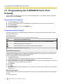
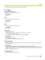
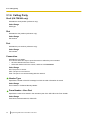
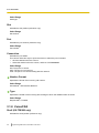
Programming Manual
for Virtual SIP Trunk Card
Pure IP-PBX
KX-TDE100
KX-TDE200/KX-TDE600
Model No.
Thank you for purchasing a Panasonic Pure IP-PBX.
Please read this manual carefully before using this product and save this manual for future use.
KX-TDE100/KX-TDE200: PMMPR Software File Version 2.0000 or later
KX-TDE600: PGMPR Software File Version 2.0000 or later
In this manual, the suffix of each model number (e.g., KX-TDE100NE) is omitted unless necessary.
Table of Contents
Table of Contents
1 Overview ...................................................................................................3
1.1
1.2
1.2.1
1.2.2
1.2.3
1.3
Information about IP Telephony Service ........................................................................4
Important Notice for Subscription and Installation .......................................................7
Port Requirements ...........................................................................................................7
Firewall Requirements ......................................................................................................7
Bandwidth Requirements .................................................................................................8
Specifications ....................................................................................................................9
2 Preparations for PC Programming .......................................................11
2.1
2.1.1
2.2
Maintenance Console Operating Instructions ..............................................................12
Installing and Starting the Maintenance Console ...........................................................12
Installing the V-SIPGW16 Card to the PBX ...................................................................16
3 Programming the V-SIPGW16 Card ......................................................17
3.1
3.1.1
3.1.2
3.1.3
3.1.4
3.1.5
3.1.6
3.1.7
3.1.8
3.1.9
3.1.10
3.1.11
3.1.12
3.1.13
3.2
3.2.1
3.3
3.3.1
3.3.2
Programming the V-SIPGW16 Card—Port Property ....................................................18
Main ................................................................................................................................19
Account ..........................................................................................................................20
Register ..........................................................................................................................22
NAT ................................................................................................................................23
Option .............................................................................................................................24
Calling Party ...................................................................................................................26
Called Party ....................................................................................................................27
Voice/FAX ......................................................................................................................28
RTP/RTCP .....................................................................................................................31
T.38 ................................................................................................................................32
T.38 Option .....................................................................................................................34
DSP ................................................................................................................................35
Supplementary Service ..................................................................................................36
Programming the V-SIPGW16 Card—Card Property ...................................................39
Card Property .................................................................................................................39
Programming the V-SIPGW16 Card—Shelf Property ..................................................42
Main ................................................................................................................................42
Timer ..............................................................................................................................45
4 Maintenance ...........................................................................................47
4.1
4.1.1
4.1.2
Configuration Management ............................................................................................48
Importing/Exporting V-SIPGW16 Provider Profiles ........................................................48
V-SIPGW16 Protocol Trace ...........................................................................................49
Index..............................................................................................................51
2
Programming Manual for Virtual SIP Trunk Card
Section 1
Overview
This section provides an overview of the V-SIPGW16
card.
Programming Manual for Virtual SIP Trunk Card
3
1.1 Information about IP Telephony Service
1.1 Information about IP Telephony Service
The Virtual 16-Channel SIP Trunk Card (V-SIPGW16) is a virtual trunk card which is designed to be easily
integrated into an Internet Telephony Service provided by an ITSP (Internet Telephony Service Provider).
As a major SIP Provider, an ITSP provides its telephony service partly through the conventional telephone
network (e.g., ISDN and Mobile), which is fee-based. An ISP (Internet Service Provider), another major SIP
Provider, does not provide telephone connection itself. However, providing its users with Internet access, an
ISP provides voice communication on the Internet for free. In this way, with VoIP technology based on the SIP
protocol, the cost of voice communication can be much cheaper than conventional telephone networks. The
maximum of two V-SIPGW16 cards can be installed to the virtual trunk slots of the PBX. Therefore, the channel
capacity of the card allows users to connect to up to 32 each different ISP/ITSPs.
V-SIPGW16 Connection Outline
The following diagram illustrates a simple VoIP network connecting the V-SIPGW16 card to the Internet.
WAN (Wide Area Network)
Internet
ITSP
Local
Telephone
ISP
LAN
(Local Area Network)
Router
Switching
Hub
PC
IP-PT
PBX with
V-SIPGW16 Card
Requirements for Internet Telephony Service
• You need to subscribe with an ISP for Internet connection.
• You need to subscribe with an ITSP for telephone connection. The ISP and ITSP may be part of the same
company.
Note
•
4
VoIP communication using the V-SIPGW16 card may deteriorate depending on the ITSP being used.
Programming Manual for Virtual SIP Trunk Card
1.1 Information about IP Telephony Service
•
VoIP communication using the V-SIPGW16 card may deteriorate depending on the network conditions.
DNS (Domain Name System)
A DNS server normally provides the name resolution service for your computer. As domain names are
alphabetic, they are easier to remember. The Internet, however, is based on IP addresses. Therefore, every
time a domain name is used, a DNS server must translate the name into the corresponding IP address, and
vice versa. For example, the domain name www.example.com may be translated to 192.0.34.166. If one DNS
server does not know how to translate a particular domain name, it asks another one, and so on, until the
correct IP address is returned.
NAT (Network Address Translation) Traversal
When NAT/NAPT (Network Address Port Translation) is enabled, the router translates a local IP address from
the PBX into a global IP address. However, the router with NAT enabled does not translate local IP addresses
stored in SIP messages into global IP addresses.
Therefore, the address which the SIP Server recognises as the destination IP address to reply to is actually
the local IP address of the PBX, not the global IP address of the router. Therefore, if the SIP server receives
a SIP message from the PBX and sends a message back to the PBX using the address stored in the SIP
message, the packet information will not reach the PBX.
STUN Servers function to solve the global IP address problem under certain NAT conditions, for example, in
case of full duplex communication. A STUN Server, used alongside the SIP Server, finds out the global IP
address of the router with NAT enabled. With the STUN feature enabled, the packet information sent by the
SIP Server is able to "traverse" NAT and reach the PBX.
The settings can be configured to specify whether to enable the NAT Traversal feature for each ISP/ITSP. In
addition, the NAT Traversal method can be selected from "STUN" and "Fixed IP Address" (refer to
3.3.1 Main, NAT Traversal).
The V-SIPGW16 card may require the NAT Traversal feature to be enabled to connect to the WAN via a router.
The following diagram illustrates how VoIP communication is enabled between the V-SIPGW16 card and the
SIP Server (SIP Receiver) via a router with NAT enabled.
Programming Manual for Virtual SIP Trunk Card
5
1.1 Information about IP Telephony Service
WAN
Internet
STUN
STUN
Server
Fixed IP Address
SIP
Server
SIP
Server
ISP/ITSP
ISP/ITSP
LAN
Router
(NAT enabled)
Switching
Hub
PC
IP-PT
PBX with
V-SIPGW16 Card
Note
•
•
6
If an ISP/ITSP uses a device such as SBC (Session Border Controller), you may not have to enable
the NAT Traversal feature.
A STUN Server is supplied by an ISP/ITSP, and not included with the PBX.
Programming Manual for Virtual SIP Trunk Card
1.2.2 Firewall Requirements
1.2 Important Notice for Subscription and Installation
1.2.1 Port Requirements
Required Ports for Each Channel
When configuring a router with NAT enabled, you need to secure a certain number of ports for each SIP and
RTP/RTCP channel. For RTP/RTCP, the number of required ports is double the number of activated SIP trunks
(Ch). For SIP signalling, the number of required ports is always one regardless of the number of activated SIP
trunks (Ch).
<Example>
If 4 SIP trunk channels are activated, you need the following number of ports:
Protocol Type
Required Port
RTP
4
RTCP
4
SIP
1
Total
9
1.2.2 Firewall Requirements
If the VoIP network contains a firewall, you must configure the firewall to allow VoIP packets to pass through
certain ports of the ports listed below without being blocked by filtering. The ports for which you need to
configure the firewall may vary depending on the network conditions.
For more information, consult your network administrator.
[IP Packets to V-SIPGW16 Card]
Port
TCP/UDP
Default Port No.
SIP Client Port
UDP
35060
STUN Client Port
UDP
33478
NAT Voice (RTP) UDP Port
UDP
16000 to N
DNS (Client) Port
UDP
30053
[IP Packets from V-SIPGW16 Card]
Port
TCP/UDP
Default Port No.
SIP Server Port
UDP
5060
Registrar Server Port
UDP
5060
STUN Server Port
UDP
3478
Manual DNS Server Port
UDP
53
Programming Manual for Virtual SIP Trunk Card
7
1.2.3 Bandwidth Requirements
Router Requirements
•
Port Forwarding:
It may be necessary to set the NAT router so that it forwards the incoming packets to the IP address of the
V-SIPGW16 card if all of the following conditions are met:
– the PBX uses a STUN server;
– a V-SIPGW16 card is located under a NAT router;
– incoming packets are routed to a SIP Client port or NAT Voice (RTP) UDP port indicated in the [IP
Packets to V-SIPGW16 Card] table above.
•
SIP-NAT Feature:
When a V-SIPGW16 card is located under a NAT router that supports the SIP-NAT feature*1, it is
recommended to disable this feature.
*1
When NAT is enabled, the router translates the IP address stored in the IP header and the port number stored in the UDP header.
When SIP-NAT is enabled, the router also translates the IP address and port number stored in SIP messages.
1.2.3 Bandwidth Requirements
When using the V-SIPGW16 card, you must ensure that the WAN has enough bandwidth to support VoIP
communications. Refer to the table below and ensure that the sum of the required bandwidth for each channel
is smaller than the amount the WAN (e.g., ADSL network) can provide.
Note that the amount in the table is only a guide. Subscribe to a network that has enough bandwidth. If the
amount of bandwidth required for VoIP communications is larger than what the network can accommodate,
speech quality will be compromised.
Required Bandwidth for Each Channel
The required bandwidth depends on what combination of CODECs and packet sending interval is used. Keep
in mind the following points about the type of CODEC and packet sending interval, in terms of the speech
quality:
• The speech quality of the CODECs varies as follows: G.711 (High), G.729 (Low)
• The shorter the packet sending interval, the higher the speech quality.
• The higher the speech quality the V-SIPGW16 card provides, the more bandwidth the WAN requires.
Packet Sending Interval
CODEC
10 ms
8
20 ms
30 ms
40 ms
50 ms
60 ms
G.711
110.4 kbps
87.2 kbps
79.5 kbps
75.6 kbps
73.3 kbps
71.7 kbps
G.729
54.4 kbps
31.2 kbps
23.5 kbps
19.6 kbps
17.3 kbps
15.7 kbps
Programming Manual for Virtual SIP Trunk Card
1.3 Specifications
1.3 Specifications
For details about the RFCs and protocols for the V-SIPGW16 card, refer to the following specifications.
Items
SIP RFCs
Specification
RFC3261 (UDP only)
RFC3262 (PRACK)
RFC3264 (Offer/Answer)
RFC3311 (UPDATE)
RFC3581 (Symmetric Response Routing/rport)
RFC4028 (Session Timer)
CODECs
G.711 (a-law and µ-law)
G.729A
Voice Options
Echo Cancellation (48 ms)
Jitter Buffer (200 ms)
VAD (Voice Activity Detection)
PLC (Packet Loss Concealment)
DTMF Relay
Inband/Outband (RFC2833)
Fax Relay
G.711 Inband/T.38
Protocol/Function
RTP
RTCP
DNS (A/SRV)
NAT Traversal (STUN)
QoS (ToS field setting in IP header of RTP/RTCP)
Programming Manual for Virtual SIP Trunk Card
9
1.3 Specifications
10
Programming Manual for Virtual SIP Trunk Card
Section 2
Preparations for PC Programming
This section serves as reference operating instructions
when using the Maintenance Console software to
programme the V-SIPGW16 card.
Programming Manual for Virtual SIP Trunk Card
11
2.1.1 Installing and Starting the Maintenance Console
2.1 Maintenance Console Operating Instructions
2.1.1 Installing and Starting the Maintenance Console
System programming, diagnosis and administration for the V-SIPGW16 card can be performed with a PC using
the Maintenance Console. This section describes how to install and start the Maintenance Console.
System Requirements
Required Operating System
• Microsoft® Windows® XP or Windows Vista® Business
Minimum Hardware Requirements
• HDD: 100 MB of available hard disk space
Recommended Display Settings
• Screen resolution: XGA (1024 ´ 768)
• DPI setting: Normal size (96 DPI)
Hardware Requirements
•
•
Make sure that the PBX, IPCMPR (for KX-TDE100/KX-TDE200)/IPCEMPR (for KX-TDE600) card, and
DSP card are installed.
Make sure that the PBX is fully connected to your PC.
Note
For details about installation, refer to "Section 3 Installation" in the Installation Manual.
Trademarks
•
•
•
Microsoft, Windows and Windows Vista are either registered trademarks or trademarks of Microsoft
Corporation in the United States and/or other countries.
All other trademarks identified herein are the property of their respective owners.
Microsoft product screen shot(s) reprinted with permission from Microsoft Corporation.
Copyright for MD5
This software uses the Source Code of RSA Data Security, Inc. described in the RFC1321
(MD5Message-Digest Algorithm).
Copyright (C) 1991-2, RSA Data Security, Inc. Created 1991. All rights reserved.
Licence to copy and use this software is granted provided that it is identified as the "RSA Data Security, Inc.
MD5 Message-Digest Algorithm" in all material mentioning or referencing this software or this function.
Licence is also granted to make and use derivative works provided that such works are identified as "derived
from the RSA Data Security, Inc. MD5 Message-Digest Algorithm" in all material mentioning or referencing the
derived work.
12
Programming Manual for Virtual SIP Trunk Card
2.1.1 Installing and Starting the Maintenance Console
RSA Data Security, Inc. makes no representations concerning either the merchantability of this software or
the suitability of this software for any particular purpose. It is provided "as is" without express or implied warranty
of any kind.
These notices must be retained in any copies of any part of this documentation and/or software.
Installing the Maintenance Console
Note
•
•
•
•
Make sure to install and use the latest version of the Maintenance Console.
To install or uninstall the software on a PC running Windows XP Professional, you must be logged in
as a user in either the "Administrators" or "Power Users" group.
To install or uninstall the software on a PC running Windows Vista Business, you must be logged in
as a user in the "Administrators" group.
Product specifications, including text displayed by the software, are subject to change without notice.
1. Copy the setup file of the Maintenance Console to your PC.
2. Double-click the setup file to run the installer.
3. Follow the on-screen instructions provided by the installation wizard.
Starting the Maintenance Console and Assigning the Basic Items (Quick
Setup)
When you start the Maintenance Console with the Installer Level Programmer Code and connect to the PBX
for the first time after initialisation (with the factory default setting), Quick Setup will launch automatically. During
Quick Setup, you will set up the basic items. For details about the basic items, refer to "2.3.4 Quick Setup" in
the Feature Guide.
1.
Connect the PC to the PBX with an Ethernet straight cable or RS-232C cross cable.
2.
Start the Maintenance Console from the Start menu.
3.
"Information before programming" appears.
a. Carefully read this important additional information, which includes updates to this and other
manuals.
b. Click OK to close this window.
4.
a. Enter the Installer Level Programmer Code (default: INSTALLER).
b. Click OK.
5.
Click Connect.
6.
a. Select your PBX model from PBX Model.
b. Select the LAN or RS-232C tab, depending on the type of PC connection with the PBX.
c. Specify the settings as required.
Note
When connecting to the PBX for the first time selecting LAN, the IP Address and Port
Number must be set to 192.168.0.101 and 35300 respectively.
d. Enter the system password for installer (default: 1234).
e. Click Connect.
Programming Manual for Virtual SIP Trunk Card
13
2.1.1 Installing and Starting the Maintenance Console
7.
When country/area data do not match:
a. Click OK to replace the country/area data of the PBX. Replacement may take several minutes to
complete.
b. Follow the procedure described in Section "3.16.1 Starting the PBX (for KX-TDE100/
KX-TDE200)" or Section "3.18.1 Starting the PBX (for KX-TDE600)" in the Installation Manual
and restart the PBX.
c. Repeat step 5 to reconnect the Maintenance Console to the PBX.
8.
Follow the instructions of the Quick Setup wizard for the basic items in Quick Setup—Step 1 to 3.
9.
In Quick Setup—Step 4, the IP addressing information for the IPCMPR/IPCEMPR card can be
assigned automatically through a DHCP server or entered manually.
When using a DHCP server:
a. Select Enable for the DHCP Client setting.
b. Click Apply.
Note
The boxes will turn grey and the IP addresses will be assigned automatically after the PBX is reset.
When not using a DHCP server:
a. Select Disable for the DHCP Client setting.
b. For KX-TDE100/KX-TDE200, type the IP address of the IPCMPR card in the IP Address for
IPCMPR Card box. For KX-TDE600, type the IP address of the IPCEMPR card in the IP Address
for IPCEMPR Card box.*1
c. In the IP Address for VoIP-DSP box, type the IP address of the DSP16 or DSP64 card.*2
d. In the Subnet Mask box, type the subnet mask address of the network.*3
e. In the Default Gateway box, type the IP address of the default gateway.*4
f. Click Apply.
When using a DHCP server to obtain a DNS server IP address automatically:
a. Select DHCP for the DNS Server Address Method setting.
b. Click Apply.
Note
The boxes will turn grey and the IP addresses will be assigned automatically after the PBX is reset.
14
Programming Manual for Virtual SIP Trunk Card
2.1.1 Installing and Starting the Maintenance Console
When not using a DHCP server to obtain a DNS server IP address automatically:
a. Select Manual for the DNS Server Address Method setting.
b. In the Manual Preferred DNS Server IP Address box, type the IP address of the preferred DNS
server.
c. In the Manual Alternate DNS Server IP Address box, type the IP address of the alternate DNS
server.
d. Click Apply.
The system menu appears. You may now begin programming the PBX.
Notice
•
•
•
*1
*2
*3
*4
Do not change the IP addresses of the IPCMPR/IPCEMPR and DSP cards once IP telephones
are registered to the PBX using these IP addresses.
The IP telephones will not operate properly if these IP addresses are changed.
A DHCP server must be able to use a "client identifier" option specified by RFC 2131.
The PBX will not start properly if the IP addresses cannot be assigned automatically by the
DHCP server when DHCP Client is set to Enable. In this case, you need to consult your
network administrator because the DHCP server on your network may not be running or a
network failure may have occurred. If the DHCP server cannot be available, change the DHCP
Client setting to Disable and set fixed IP addresses, then restart the PBX.
To change the DHCP Client setting, connect the PC with an RS-232C cross cable or Ethernet
straight cable. When connecting the PC with an Ethernet straight cable, make sure the PBX
is disconnected from the LAN and then connect the PC with an Ethernet straight cable using
192.168.0.101 for the IP address of the IPCMPR/IPCEMPR card.
Valid IP address range: "1.0.0.0" to "223.255.255.255"
Valid IP address range: "1.0.0.0" to "223.255.255.255"
Valid subnet mask address range: "0–255.0–255.0–255.0–255" (except 0.0.0.0 and 255.255.255.255)
Valid IP address range: "1.0.0.0" to "223.255.255.255"
Programming Manual for Virtual SIP Trunk Card
15
2.2 Installing the V-SIPGW16 Card to the PBX
2.2 Installing the V-SIPGW16 Card to the PBX
16
1.
a. Under Configuration, click Slot.
b. Move the mouse pointer over the white PBX image at the bottom of the screen for the virtual slots.
c. Click Select Shelf.
2.
a. Click on the name of the V-SIPGW16 card. An image of the card will be displayed.
b. Drag the image of the card to a Trunk slot and release it. The card will move into the slot space.
3.
Click Yes to confirm.
Programming Manual for Virtual SIP Trunk Card
Section 3
Programming the V-SIPGW16 Card
This section serves as reference operating instructions
when using the Maintenance Console software to
programme the V-SIPGW16 card.
Programming Manual for Virtual SIP Trunk Card
17
3.1 Programming the V-SIPGW16 Card—Port Property
3.1 Programming the V-SIPGW16 Card—Port
Property
Various settings can be programmed for each virtual SIP gateway port. To change the status of virtual SIP
gateway ports, click Command.
Accessing Port Properties
1.
2.
3.
4.
5.
Under Configuration, click Slot.
Move the mouse pointer over the white PBX image at the bottom of the screen for the virtual slots.
Click Select Shelf.
Move the mouse pointer over the V-SIPGW16 card.
Click Port Property.
Programming Port Property
Some of the parameters can be automatically programmed by selecting the desired SIP provider for each
virtual SIP gateway port.
Icon Description
In this section, the following icons show the different parameter type.
Icon
Description for Parameter Type
Programmed automatically by selecting the desired SIP provider in Select Provider.
Manual programming is compulsory.
Manual programming is compulsory under certain conditions.
Not marked
Manual programming is optional.
Automatic Programming
Some of the parameters on this screen can be automatically programmed by selecting the desired SIP provider
for each virtual SIP gateway port. A maximum of 32 SIP providers can be programmed, and a different SIP
provider can be assigned to each virtual SIP gateway port.
Follow the steps below to configure a SIP provider.
1. Click Select Provider.
A dialogue box will appear. Available virtual SIP gateway port numbers are displayed in the list.
2. From the Provider menu, select the desired SIP provider.
3. Highlight the desired port numbers or click Select All to select all the virtual SIP gateway port numbers to
be assigned to the SIP provider selected in step 2.
4. Click Execute.
5. Click OK.
6. Click Apply.
Appropriate setting values designated by the SIP provider will be set in the parameters for the virtual SIP
gateway ports.
Manual Programming
Follow the steps below to programme the parameters which are not automatically programmed by selecting a
provider.
1. Click a desired tab.
18
Programming Manual for Virtual SIP Trunk Card
3.1.1 Main
2. Enter information or select from the list for each parameter.
3.1.1 Main
Shelf (KX-TDE600 only)
Indicates the shelf position (reference only).
Value Range
Shelf type
Slot
Indicates the slot position (reference only).
Value Range
Slot number
Port
Indicates the port number (reference only).
Value Range
Port number
Connection
Indicates the port status.
This column offers two ways to open the screen to select the port command:
• Click the desired cell in the column.
• Select the desired cell in the column, and then click Command.
Value Range
INS: The port is in service.
OUS: The port is out of service.
Fault: The port is not communicating with the network.
Channel Attribute
Specifies the channel property of each port to enable several sessions to be performed for one subscription
with the SIP provider.
Value Range
Basic channel: The subscriber channel that is assigned the SIP registration information.
Additional channel for ChN (N=1–16): The subordinative channel that uses the same registration information
as a Basic channel for SIP sessions. Select the Basic channel number to which the Additional channel belongs.
Not Used: The channel is not in use.
Provider Name
Specifies the name of the SIP provider.
Programming Manual for Virtual SIP Trunk Card
19
3.1.2 Account
Value Range
Max. 20 characters
SIP Server Location—Name
Specifies the domain name of the SIP proxy server.
Note
Specify the domain name of the outbound proxy server, if provided by the SIP provider.
Value Range
Max. 100 characters
SIP Server Location—IP Address
Specifies the IP address of the SIP proxy server. This setting is compulsory when not using the DNS server.
Note
Specify the IP address of the outbound proxy server, if provided by the SIP provider.
Value Range
1.0.0.0–223.255.255.255
SIP Server Port Number
Specifies the port number of the SIP proxy server.
Value Range
1–65535
SIP Service Domain
Specifies the domain name provided by the SIP provider.
Value Range
Max. 100 characters
Subscriber Number
Specifies the number used as the CLIP number.
Value Range
Max. 16 digits (consisting of 0–9, *, and #)
3.1.2 Account
Shelf (KX-TDE600 only)
Indicates the shelf position (reference only).
20
Programming Manual for Virtual SIP Trunk Card
3.1.2 Account
Value Range
Shelf type
Slot
Indicates the slot position (reference only).
Value Range
Slot number
Port
Indicates the port number (reference only).
Value Range
Port number
Connection
Indicates the port status.
This column offers two ways to open the screen to select the port command:
• Click the desired cell in the column.
• Select the desired cell in the column, and then click Command.
Value Range
INS: The port is in service.
OUS: The port is out of service.
Fault: The port is not communicating with the network.
User Name
Specifies the user name (SIP Account) provided by the SIP provider.
Value Range
Max. 64 characters
Authentication ID
Specifies the authentication ID required for registration with the SIP server.
Value Range
Max. 64 characters
Authentication Password
Specifies the authentication password used for registration with the SIP provider.
Value Range
Max. 32 characters
Programming Manual for Virtual SIP Trunk Card
21
3.1.3 Register
3.1.3 Register
Shelf (KX-TDE600 only)
Indicates the shelf position (reference only).
Value Range
Shelf type
Slot
Indicates the slot position (reference only).
Value Range
Slot number
Port
Indicates the port number (reference only).
Value Range
Port number
Connection
Indicates the port status.
This column offers two ways to open the screen to select the port command:
• Click the desired cell in the column.
• Select the desired cell in the column, and then click Command.
Value Range
INS: The port is in service.
OUS: The port is out of service.
Fault: The port is not communicating with the network.
Register Ability
Specifies whether to send the REGISTER message to the SIP server.
Value Range
Disable, Enable
Register Sending Interval
Specifies the maximum length of interval time after which the PBX sends the REGISTER message.
Value Range
10–86400 s
22
Programming Manual for Virtual SIP Trunk Card
3.1.4 NAT
Un-Register Ability when port INS
Specifies whether to unregister the previous registration and send the REGISTER message to the SIP server
when the port status is set back to INS.
Value Range
Disable, Enable
Registrar Server—Name
Specifies the domain name of the SIP registrar server.
Value Range
Max. 100 characters
Registrar Server—IP Address
Specifies the IP address of the SIP registrar server. This setting is compulsory when a register IP address is
provided.
Value Range
1.0.0.0–223.255.255.255
Registrar Server Port Number
Specifies the port number of the SIP registrar server.
Value Range
1–65535
3.1.4 NAT
Shelf (KX-TDE600 only)
Indicates the shelf position (reference only).
Value Range
Shelf type
Slot
Indicates the slot position (reference only).
Value Range
Slot number
Port
Indicates the port number (reference only).
Value Range
Port number
Programming Manual for Virtual SIP Trunk Card
23
3.1.5 Option
Connection
Indicates the port status.
This column offers two ways to open the screen to select the port command:
• Click the desired cell in the column.
• Select the desired cell in the column, and then click Command.
Value Range
INS: The port is in service.
OUS: The port is out of service.
Fault: The port is not communicating with the network.
STUN Server—Name
Specifies the domain name of a STUN server.
Value Range
Max. 100 characters
STUN Server—IP Address
Specifies the IP address of the STUN server. This setting is compulsory when the STUN method is selected
and a DNS server is not used.
Value Range
1.0.0.0–223.255.255.255
STUN Server Port Number
Specifies the port number of the STUN server.
Value Range
1–65535
3.1.5 Option
Shelf (KX-TDE600 only)
Indicates the shelf position (reference only).
Value Range
Shelf type
Slot
Indicates the slot position (reference only).
Value Range
Slot number
24
Programming Manual for Virtual SIP Trunk Card
3.1.5 Option
Port
Indicates the port number (reference only).
Value Range
Port number
Connection
Indicates the port status.
This column offers two ways to open the screen to select the port command:
• Click the desired cell in the column.
• Select the desired cell in the column, and then click Command.
Value Range
INS: The port is in service.
OUS: The port is out of service.
Fault: The port is not communicating with the network.
Session Refresh (Session Timer)—Session Timer Ability
Enables the PBX to periodically refresh SIP sessions by sending repeated requests.
Value Range
Disable: This feature is not activated.
Enable (Active): Activates this feature only if the other device supports the feature.
Enable (Passive): Activates this feature only when requested by the other device.
Session Refresh (Session Timer)—Session Expire Timer
Specifies the length of time that the PBX waits before terminating SIP sessions when no reply to the repeated
requests is received.
Value Range
90–3600 s
Session Refresh (Session Timer)—Refresh Method
Specifies the type of request that the PBX sends to periodically refresh SIP sessions.
Value Range
UPDATE, re-INVITE
Proxy-Require Option
Specifies option tags in a Proxy-Require header field so that the SIP server is notified that the client is behind
a router with NAT enabled and firewall.
Value Range
Max. 100 characters
Programming Manual for Virtual SIP Trunk Card
25
3.1.6 Calling Party
3.1.6 Calling Party
Shelf (KX-TDE600 only)
Indicates the shelf position (reference only).
Value Range
Shelf type
Slot
Indicates the slot position (reference only).
Value Range
Slot number
Port
Indicates the port number (reference only).
Value Range
Port number
Connection
Indicates the port status.
This column offers two ways to open the screen to select the port command:
• Click the desired cell in the column.
• Select the desired cell in the column, and then click Command.
Value Range
INS: The port is in service.
OUS: The port is out of service.
Fault: The port is not communicating with the network.
Header Type
Specifies the header of the SIP message in which the caller information is stored.
Value Range
From Header, P-Preferred-Identity Header
From Header—User Part
Specifies the value to be stored in the username part of the SIP-URI of the From header.
Value Range
User Name, Authentication ID, PBX-CLIP
26
Programming Manual for Virtual SIP Trunk Card
3.1.7 Called Party
From Header—SIP-URI
Specifies the complete SIP-URI address of the From header. The configuration in From Header—User Part
will be invalid if this parameter is set.
Value Range
Max. 100 characters
P-Preferred-Identity Header—User Part
Specifies the value to be stored in the username part of the SIP-URI of the P-Preferred-Identity header.
Value Range
User Name, Authentication ID, PBX-CLIP
P-Preferred-Identity Header—SIP-URI
Specifies the complete SIP-URI address of the P-Preferred-Identity header. The configuration in
P-Preferred-Identity Header—User Part will be invalid if this parameter is set.
Value Range
Max. 100 characters
Number Format
Selects the format of the CLIP number to be sent to the called party.
Value Range
International, +International, National
Remove Digit
Specifies the number of leading digits of the CLIP number to be removed. This setting is compulsory when
PBX-CLIP is selected in From Header—User Part or P-Preferred-Identity Header—User Part.
Value Range
0–32
Additional Dial
Specifies the number to be added to the CLIP number in the place of the removed digits. This setting is
compulsory when PBX-CLIP is selected in From Header—User Part or P-Preferred-Identity Header—User
Part.
Value Range
Max. 20 digits (containing of 0–9, *, and #)
3.1.7 Called Party
Shelf (KX-TDE600 only)
Indicates the shelf position (reference only).
Programming Manual for Virtual SIP Trunk Card
27
3.1.8 Voice/FAX
Value Range
Shelf type
Slot
Indicates the slot position (reference only).
Value Range
Slot number
Port
Indicates the port number (reference only).
Value Range
Port number
Connection
Indicates the port status.
This column offers two ways to open the screen to select the port command:
• Click the desired cell in the column.
• Select the desired cell in the column, and then click Command.
Value Range
INS: The port is in service.
OUS: The port is out of service.
Fault: The port is not communicating with the network.
Number Format
Specifies the format of an incoming call number.
Value Range
International, +International, National
Type
Specifies the header of the incoming SIP message in which the dialled number is stored.
Value Range
Request-URI, To header
3.1.8 Voice/FAX
Shelf (KX-TDE600 only)
Indicates the shelf position (reference only).
28
Programming Manual for Virtual SIP Trunk Card
3.1.8 Voice/FAX
Value Range
Shelf type
Slot
Indicates the slot position (reference only).
Value Range
Slot number
Port
Indicates the port number (reference only).
Value Range
Port number
Connection
Indicates the port status.
This column offers two ways to open the screen to select the port command:
• Click the desired cell in the column.
• Select the desired cell in the column, and then click Command.
Value Range
INS: The port is in service.
OUS: The port is out of service.
Fault: The port is not communicating with the network.
IP Codec Priority—1st, 2nd, 3rd
Specifies the priority of the CODECs to be used. None is only available for 2nd and 3rd priorities.
Value Range
G.711A, G.711µ, G.729A, None
Packet Sampling Time (G.711A)
Specifies the time interval between measurements (samples) of sound data during a conversation. The smaller
this number, the higher the quality of the transmitted sound.
Value Range
10 ms, 20 ms, 30 ms, 40 ms, 50 ms, 60 ms
Packet Sampling Time (G.711µ)
Specifies the time interval between measurements (samples) of sound data during a conversation. The smaller
this number, the higher the quality of the transmitted sound.
Value Range
10 ms, 20 ms, 30 ms, 40 ms, 50 ms, 60 ms
Programming Manual for Virtual SIP Trunk Card
29
3.1.8 Voice/FAX
Packet Sampling Time (G.729A)
Specifies the time interval between measurements (samples) of sound data during a conversation. The smaller
this number, the higher the quality of the transmitted sound.
Value Range
10 ms, 20 ms, 30 ms, 40 ms, 50 ms, 60 ms
Voice Activity Detection for G.711
Enables the use of the Voice Activity Detection feature for the G.711 CODEC. This feature conserves
bandwidth by detecting silent periods during a call and suppressing the packets of silence from being sent to
the network.
Value Range
Disable, Enable
FAX Sending Method
Specifies the method of transporting the fax signal.
Value Range
G.711 Inband, T.38
Maximum Bit Rate
Specifies the maximum bit rate of the fax signal.
Value Range
No Speed Limit, 2400 bps, 4800 bps, 7200 bps, 9600 bps, 12000 bps, 14400 bps
FAX Detection Ability
Enables the use of the FAX Detection Ability feature. This feature enables end-to-end fax signal relay when
the other party prefers a CODEC other than G.711. This feature functions only if the other party supports G.
711.
Value Range
Disable, Enable
DTMF
Specifies the method to transport DTMF tones.
Value Range
Inband, Outband (RFC2833)
Payload Type
Specifies the payload type of RFC2833 for DTMF tones.
30
Programming Manual for Virtual SIP Trunk Card
3.1.9 RTP/RTCP
Note
Manual programming is required if DTMF is set to Outband (RFC2833).
Value Range
96–127
3.1.9 RTP/RTCP
Shelf (KX-TDE600 only)
Indicates the shelf position (reference only).
Value Range
Shelf type
Slot
Indicates the slot position (reference only).
Value Range
Slot number
Port
Indicates the port number (reference only).
Value Range
Port number
Connection
Indicates the port status.
This column offers two ways to open the screen to select the port command:
• Click the desired cell in the column.
• Select the desired cell in the column, and then click Command.
Value Range
INS: The port is in service.
OUS: The port is out of service.
Fault: The port is not communicating with the network.
RTP QoS Ability
Specifies the type of value to be stored in the ToS field in the IP header.
Value Range
ToS, DSCP, HEX
RTP QoS-ToS Priority
Specifies the priority level in the ToS field.
Programming Manual for Virtual SIP Trunk Card
31
3.1.10 T.38
Value Range
0–7
RTP QoS-ToS Type
Specifies the ToS type in the ToS field.
Value Range
Normal, Monetary Cost, Reliability, Throughput, Delay
RTP QoS-DSCP
Specifies the value in the ToS field by a DSCP for DiffServ.
Value Range
0–63
RTP QoS-HEX
Specifies the value in the ToS field by a hexadecimal number.
Value Range
00–FF
RTCP Packet Sending Ability
Specifies whether to enable each port to send RTCP packets.
Value Range
Disable, Enable
RTCP Packet Interval
Specifies the interval time until the next RTCP packet is sent.
Value Range
5–60 s
3.1.10 T.38
Shelf (KX-TDE600 only)
Indicates the shelf position (reference only).
Value Range
Shelf type
Slot
Indicates the slot position (reference only).
32
Programming Manual for Virtual SIP Trunk Card
3.1.10 T.38
Value Range
Slot number
Port
Indicates the port number (reference only).
Value Range
Port number
Connection
Indicates the port status.
This column offers two ways to open the screen to select the port command:
• Click the desired cell in the column.
• Select the desired cell in the column, and then click Command.
Value Range
INS: The port is in service.
OUS: The port is out of service.
Fault: The port is not communicating with the network.
T.38 FAX Max Datagram
Specifies the maximum datagram size when using the T.38 protocol.
Value Range
272–512
T.38 FAX UDPTL Error Correction – Redundancy
Specifies whether to enable the redundancy feature when using the T.38 protocol.
Value Range
Disable, Enable
T.38 FAX UDPTL Redundancy count for T.30 messages
Specifies the redundancy count for T.30 messages when using the T.38 protocol.
Value Range
0–7
T.38 FAX UDPTL Redundancy count for data
Specifies the redundancy count for data when using the T.38 protocol.
Value Range
0–3
Programming Manual for Virtual SIP Trunk Card
33
3.1.11 T.38 Option
T.38 FAX Rate Management Method
Specifies the rate management method when using the T.38 protocol.
Value Range
Transferred TCF, Local TCF
3.1.11 T.38 Option
Shelf (KX-TDE600 only)
Indicates the shelf position (reference only).
Value Range
Shelf type
Slot
Indicates the slot position (reference only).
Value Range
Slot number
Port
Indicates the port number (reference only).
Value Range
Port number
Connection
Indicates the port status.
This column offers two ways to open the screen to select the port command:
• Click the desired cell in the column.
• Select the desired cell in the column, and then click Command.
Value Range
INS: The port is in service.
OUS: The port is out of service.
Fault: The port is not communicating with the network.
T.38 FAX QoS Available
Specifies the type of value to be stored in the ToS field in the IP header when using the T.38 protocol.
Value Range
ToS, DSCP, HEX
T.38 FAX QoS-ToS Priority
Specifies the priority level in the ToS field when using the T.38 protocol.
34
Programming Manual for Virtual SIP Trunk Card
3.1.12 DSP
Value Range
0–7
T.38 FAX QoS-ToS Type
Specifies the ToS type in the ToS field when using the T.38 protocol.
Value Range
Normal, Monetary Cost, Reliability, Throughput, Delay
T.38 FAX QoS-DSCP
Specifies the value in the ToS field by a DSCP for DiffServ when using the T.38 protocol. This setting is
compulsory when DSCP is selected in T.38 FAX QoS Available.
Value Range
0–63
T.38 FAX QoS-HEX
Specifies the value in the ToS field by a hexadecimal number when using the T.38 protocol. This setting is
compulsory when HEX is selected in T.38 FAX QoS Available.
Value Range
00–FF
3.1.12 DSP
Shelf (KX-TDE600 only)
Indicates the shelf position (reference only).
Value Range
Shelf type
Slot
Indicates the slot position (reference only).
Value Range
Slot number
Port
Indicates the port number (reference only).
Value Range
Port number
Programming Manual for Virtual SIP Trunk Card
35
3.1.13 Supplementary Service
Connection
Indicates the port status.
This column offers two ways to open the screen to select the port command:
• Click the desired cell in the column.
• Select the desired cell in the column, and then click Command.
Value Range
INS: The port is in service.
OUS: The port is out of service.
Fault: The port is not communicating with the network.
Echo Canceller Ability
Specifies the echo canceller ability time.
Value Range
OFF, 48 ms, 128 ms
DSP Digital Gain (Down)
Specifies the DSP Digital Gain for the down voice path.
Value Range
-14–6 dB
DSP Digital Gain (Up)
Specifies the DSP Digital Gain for the up voice path.
Value Range
-14–6 dB
EC Gain
Specifies the Echo Canceller Gain.
Value Range
-14–6 dB
NLP Setting
Specifies the NLP (Non-Linear Processor) setting to control echo sound quality.
Value Range
Disable, Weak, Normal, Strong
3.1.13 Supplementary Service
Shelf (KX-TDE600 only)
Indicates the shelf position (reference only).
36
Programming Manual for Virtual SIP Trunk Card
3.1.13 Supplementary Service
Value Range
Shelf type
Slot
Indicates the slot position (reference only).
Value Range
Slot number
Port
Indicates the port number (reference only).
Value Range
Port number
Connection
Indicates the port status.
This column offers two ways to open the screen to select the port command:
• Click the desired cell in the column.
• Select the desired cell in the column, and then click Command.
Value Range
INS: The port is in service.
OUS: The port is out of service.
Fault: The port is not communicating with the network.
CLIR
Specifies whether to allow restriction of the display of the CLIP number on the called party’s telephone when
making a SIP trunk call.
Value Range
Yes, No
CNIP (Send)
Specifies whether to send the caller’s name to be displayed on the called party’s telephone when making a
SIP trunk call.
Value Range
Yes, No
CNIP (Receive)
Specifies whether to receive the caller’s name to be displayed on the called party’s telephone when receiving
a SIP trunk call.
Programming Manual for Virtual SIP Trunk Card
37
3.1.13 Supplementary Service
Value Range
Yes, No
38
Programming Manual for Virtual SIP Trunk Card
3.2.1 Card Property
3.2 Programming the V-SIPGW16 Card—Card
Property
3.2.1 Card Property
The properties of the V-SIPGW card can be specified. To programme the parameters, click Common
Settings, and set the desired value.
Accessing Card Properties
1.
2.
3.
4.
5.
Under Configuration, click Slot.
Move the mouse pointer over the white PBX image at the bottom of the screen for the virtual slots.
Click Select Shelf.
Move the mouse pointer over the V-SIPGW16 card.
Click Card Property.
Programming Card Property
Icon Description
In this section, the following icons show the different parameter type.
Icon
Description for Parameter Type
Manual programming is compulsory under certain conditions.
Not marked
Manual programming is optional.
DNS Server IP Address Method
Specifies the method of IP address assignment for a DNS server. When selecting DHCP, the DNS server IP
address can be assigned automatically by a DHCP server. When selecting Manual, the DNS server IP address
must be assigned manually.
Value Range
DHCP, Manual
DHCP Preferred DNS Server IP Address
Indicates the IP address of the preferred DNS server assigned automatically by the DHCP server (reference
only).
Value Range
1.0.0.0–223.255.255.255
DHCP Alternate DNS Server IP Address
Indicates the IP address of the alternate DNS server assigned automatically by the DHCP server (reference
only).
Programming Manual for Virtual SIP Trunk Card
39
3.2.1 Card Property
Value Range
1.0.0.0–223.255.255.255
Manual Preferred DNS Server IP Address
Specifies the IP address of the preferred DNS server manually. This setting is compulsory if a DNS server IP
address is not assigned automatically.
Value Range
1.0.0.0–223.255.255.255
Manual Alternate DNS Server IP Address
Specifies the IP address of the alternate DNS server manually.
Note
If Manual Preferred DNS Server IP Address is programmed, this setting is optional. However, if possible,
it is recommended to specify Manual Alternate DNS Server IP Address as well.
Value Range
1.0.0.0–223.255.255.255
Manual DNS Server Port Number
Specifies the port number of the DNS server.
Value Range
1–65535
DNS Port Number
Specifies the port number of the PBX used for communication with the DNS server.
Value Range
1–65535
DNS Retry Interval Timer
Specifies the length of time until a query is retried when no response is received from the DNS server.
Value Range
1–10 s
DNS Retry Counter
Specifies the number of times that a query is retried when no response is received from the DNS server.
Value Range
1–10
40
Programming Manual for Virtual SIP Trunk Card
3.2.1 Card Property
DNS SRV Record Resolve Ability
Specifies whether to request that the DNS server translates domain names into IP addresses using the DNS
SRV record.
Value Range
Disable, Enable
Programming Manual for Virtual SIP Trunk Card
41
3.3.1 Main
3.3 Programming the V-SIPGW16 Card—Shelf
Property
Common settings for all of the V-SIPGW cards installed in the IPCMPR (for KX-TDE100/KX-TDE200)/
IPCEMPR (for KX-TDE600) Virtual Shelf can be programmed.
Accessing Shelf Properties
1.
2.
3.
4.
5.
Under Configuration, click Slot.
Move the mouse pointer over the white PBX image at the bottom of the screen for the virtual slots.
Click Select Shelf.
Move the mouse pointer over the V-SIPGW16 card.
Click Shelf Property.
Programming Shelf Property
Icon Description
In this section, the following icons show the different parameter type.
Icon
Description for Parameter Type
Manual programming is compulsory under certain conditions.
Not marked
Manual programming is optional.
3.3.1 Main
SIP Client Port Number
Specifies the port number of the PBX used for communications with the SIP server.
Value Range
1–65535
NAT Traversal
Specifies the NAT traversal method.
– STUN: A STUN Server, used alongside the SIP Server, finds out the global IP address of the router with
NAT enabled.
– Fixed IP Address: The global IP address of the router with NAT enabled is fixed.
Note
Manual programming is optional except when programming is required depending on the network
conditions.
Value Range
Off, Fixed IP Addr., STUN
42
Programming Manual for Virtual SIP Trunk Card
3.3.1 Main
NAT - Voice (RTP) UDP Port No.
Specifies the starting port number of the dynamic ports used for NAT Traversal.
Value Range
2–65000 (even number only)
NAT - Keep Alive Packet Sending Ability
Specifies whether to send Keep Alive packets in order to maintain the NAT binding information. This setting
may be compulsory depending on the network conditions.
Value Range
Disable, Enable
NAT - Keep Alive Packet Type
Specifies the type of Keep Alive packets to be sent out.
Value Range
Blank UDP, None
NAT - Keep Alive Packet Sending Interval
Specifies the interval time until the next Keep Alive packet is sent.
Note
It is required to set this interval shorter than the NAT binding time of the router. The default value is
appropriate in most cases.
Value Range
1–60 s
NAT - Fixed Global IP Address
Specifies the global IP address of the router with NAT enabled. This setting is compulsory if Fixed IP Addr.
is selected in NAT Traversal.
Value Range
1.0.0.0–223.255.255.255
STUN Ability
Specifies whether to open a protocol port of the STUN server to enable STUN feature.
Value Range
Disable, Enable
STUN Client Port Number
Specifies the port number of the PBX used for communications with the STUN server.
Programming Manual for Virtual SIP Trunk Card
43
3.3.1 Main
Value Range
1–65535
STUN External Address Detection Retry Counter
Specifies the number of times that a query is retried when no response is received from the STUN server.
Value Range
0–8
STUN Resending Interval
Specifies the length of time until a query is retried when no response is received from the STUN server.
Value Range
0–1600 ms
SIP Called Party Number Check Ability
Specifies whether to receive a SIP trunk call when receiving the INVITE message with an incorrect target
SIP-URI. The setting specified here is also applied when the request header is blank or contains characters
that can not be modified to a receivable number.
Value Range
Disable (High->Low), Disable (Low->High), Enable
Symmetric Response Routing Ability
Enables this feature to request that the SIP server sends the response back to the source IP address and port
from which the request originated.
Value Range
Disable, Enable
100rel Ability
Specifies whether to add the option tag 100rel to the header field of the INVITE message.
Value Range
Disable: This feature is not activated.
Enable (Active): Activates this feature only if the other device supports the feature.
Enable (Passive): Activates this feature only when requested by the other device.
Ringback Tone to Outside Caller
Enables the PBX to send a ringback tone to an outside caller when the network cannot send the tone.
Value Range
Disable, Enable
44
Programming Manual for Virtual SIP Trunk Card
3.3.2 Timer
3.3.2 Timer
SIP T1
Specifies the retransmission interval time for INVITE requests and responses.
Value Range
5–255 ´ 100 ms
SIP T2
Specifies the retransmission interval time for INVITE responses and non-INVITE requests.
Value Range
40–255 ´ 100 ms
Programming Manual for Virtual SIP Trunk Card
45
3.3.2 Timer
46
Programming Manual for Virtual SIP Trunk Card
Section 4
Maintenance
This section serves as reference operating instructions
for data management of the V-SIPGW16 card using the
Maintenance Console software.
Programming Manual for Virtual SIP Trunk Card
47
4.1.1 Importing/Exporting V-SIPGW16 Provider Profiles
4.1 Configuration Management
4.1.1 Importing/Exporting V-SIPGW16 Provider Profiles
Provider profiles for the V-SIPGW16 card can be exported or imported (if updated provider profiles are
available), using the Import/Export tool.
Follow the steps below to import or export the provider profiles:
Note
To access the following menu options, you must be logged in to the Maintenance Console in Batch or
Interactive mode at Installer level. For details about the software mode and access level, refer to the On-line
Help.
To import provider profiles
1. From the Tool menu, point to Import, and then click V-SIPGW16 Provider to import.
2. Navigate to the folder containing the provider profiles you want to open.
3. Select the file.
4. Click Open to open the file.
5. Click OK.
To export provider profiles
1. From the Tool menu, point to Export, and then click V-SIPGW16 Provider to export.
2. Navigate to the folder in which you want to save the file.
3. Enter a file name.
4. Click Save.
5. Click OK.
48
Programming Manual for Virtual SIP Trunk Card
4.1.2 V-SIPGW16 Protocol Trace
4.1.2 V-SIPGW16 Protocol Trace
The trace data of protocol activity can be collected from the V-SIPGW16 card and saved to the PC, using the
utility, V-SIPGW16 Protocol Trace.
This option requires that the target V-SIPGW16 card be set to INS status.
Follow the steps below to trace and file V-SIPGW16 card protocol activity:
Note
To access the following menu options, you must be logged in to the Maintenance Console in Batch or
Interactive mode at Installer level. For details about the software mode and access level, refer to the On-line
Help.
To save trace data to the SD Memory Card
1. From the Utility menu, select V-SIPGW16 Protocol Trace.
When the progress bar disappears, the protocol trace is complete. The trace data has been saved to the
SD Memory Card (file name: "PRTSIPC").
To transfer trace data to the PC
1. From the Utility menu, select File Transfer PBX (SD Card) to PC.
2.
3.
4.
5.
6.
7.
The list of trace data files will be displayed.
Select the desired trace data file.
Click Transfer.
Navigate to the folder in which you want to save the file.
Enter a file name.
Click Save.
Click OK.
Programming Manual for Virtual SIP Trunk Card
49
4.1.2 V-SIPGW16 Protocol Trace
50
Programming Manual for Virtual SIP Trunk Card
Index
Programming Manual for Virtual SIP Trunk Card
51
Index
A
R
Accessing Card Properties 39
Accessing Port Properties 18
Accessing Shelf Properties 42
Automatic Programming, Port Property
Required Bandwidth for Each Channel
Router Requirements 8
18
S
SBC (Session Border Controller) 6
Shelf Property, Icon Description 42
Specifications 9
STUN 5
STUN Server 5
System Requirements 12
B
Bandwidth Requirements
8
C
Card Property, Icon Description 39
Card Property, Programming 39
Configuration Management 48
V
V-SIPGW16 Connection Outline 4
V-SIPGW16 Protocol Trace 49
D
DHCP Server 14
DNS (Domain Name System)
DNS Server 5
5
F
Firewall Requirements
Fixed IP Address 5
7
H
Hardware Requirements
12
I
Icon Description, Card Property 39
Icon Description, Port Property 18
Icon Description, Shelf Property 42
Important Notice for Subscription and Installation 7
Installing and Starting the Maintenance Console 12
Installing the V-SIPGW16 Card to the PBX 16
ISP (Internet Service Provider) 4
ITSP (Internet Telephony Service Provider) 4
M
Maintenance 47
Manual Programming, Port Property
18
N
NAT (Network Address Translation) Traversal
5
P
Port Property, Automatic Programming 18
Port Property, Icon Description 18
Port Property, Manual Programming 18
Port Requirements 7
Programming Card Property 39
Programming Port Property 18
Programming Shelf Property 42
Provider Profiles 48
Q
Quick Setup
52
13
Programming Manual for Virtual SIP Trunk Card
8
Notes
Programming Manual for Virtual SIP Trunk Card
53
Panasonic Communications Co., Ltd.
1-62, 4-chome, Minoshima, Hakata-ku, Fukuoka 812-8531, Japan
Copyright:
This material is copyrighted by Panasonic Communications Co., Ltd., and may be reproduced for internal use
only. All other reproduction, in whole or in part, is prohibited without the written consent of Panasonic
Communications Co., Ltd.
2008 Panasonic Communications Co., Ltd. All Rights Reserved.
PSQX5028ZA KK1008TE0