1
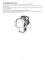
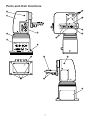
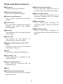
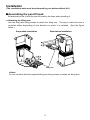
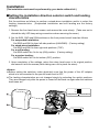
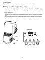
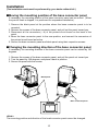
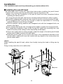
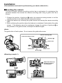
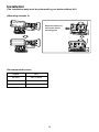
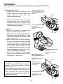
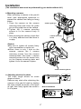
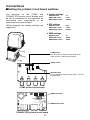
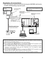
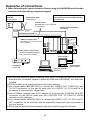
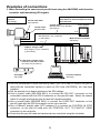
Indoor pan-tilt head
Model AW-
P
Before attempting to connect, operate or adjust this product, please
read these instructions completely.
Printed in Japan
VQT9583
F1101W @
P
CAUTION
RISK OF ELECTRIC SHOCK
DO NOT OPEN
CAUTION: TO REDUCE THE RISK OF ELECTRIC SHOCK,
DO NOT REMOVE COVER (OR BACK).
NO USER SERVICEABLE PARTS INSIDE.
REFER TO SERVICING TO QUALIFIED SERVICE PERSONNEL.
The lightning flash with arrowhead symbol, within an equilateral triangle,
is intended to alert the user to the presence of uninsulated “dangerous
voltage” within the product’s enclosure that may be of sufficient
magnitude to constitute a risk of electric shock to persons.
The exclamation point within an equilateral triangle is intended to alert the
user to the presence of important operating and maintenance (service)
instructions in the literature accompanying the appliance.
WARNING:
TO REDUCE THE RISK OF FIRE OR SHOCK HAZARD, DO NOT
EXPOSE THIS EQUIPMENT TO RAIN OR MOISTURE.
CAUTION:
TO REDUCE THE RISK OF FIRE OR SHOCK HAZARD AND ANNOYING
INTERFERENCE, USE THE RECOMMENDED ACCESSORIES ONLY.
CAUTION:
TO REDUCE THE RISK OF FIRE OR SHOCK HAZARD, REFER
CHANGE OF SWITCH SETTING INSIDE THE UNIT TO QUALIFIED
SERVICE PERSONNEL.
indicates safety information.
2
FCC Note:
This device complies with Part 15 of the FCC Rules. To assure continued
compliance follow the attached installation instructions and do not make any
unauthorized modifications.
This equipment has been tested and found to comply with the limits for a class A
digital device, pursuant to Part 15 of the FCC Rules. These limits are designed to
provide reasonable protection against harmful interference when the equipment is
operated in a commercial environment. This equipment generates, uses, and can
radiate radio frequency energy and, if not installed and used in accordance with the
instruction manual, may cause harmful interference to radio communications.
Operation of this equipment in a residential area is likely to cause harmful
interference in which case the user will be required to correct the interference at his
own expense.
Replace battery with part No. CR2032 only.
Use of another battery may present a risk of fire or explosion.
Caution—Battery may explode if mistreated.
Do not recharge, disassemble or dispose of in fire.
indicates safety information.
3
Contents
Connections . . . . . . . . . . . . . . . . . . . . .18
$ Connecting the connector panel . . .18
$ Head connector panel . . . . . . . . . . .19
$ Connecting the base connector
panel . . . . . . . . . . . . . . . . . . . . . . . .20
$ Connecting the AC adapter for use
with the pan-tilt head . . . . . . . . . . . .21
$ Setting the printed circuit board
switches . . . . . . . . . . . . . . . . . . . . . .22
Examples of connections . . . . . . . . . .23
Limiters . . . . . . . . . . . . . . . . . . . . . . . . .29
$ Setting the limiters . . . . . . . . . . . . . .30
$ Releasing the limiters . . . . . . . . . . .31
$ Resetting the limiters . . . . . . . . . . . .31
Replacement of consumable parts . . .32
Specifications . . . . . . . . . . . . . . . . . . . .33
Introduction . . . . . . . . . . . . . . . . . . . . . . .4
Accessories . . . . . . . . . . . . . . . . . . . . . .4
Installation precautions . . . . . . . . . . . . .5
Precautions for use . . . . . . . . . . . . . . . .6
Parts and their functions . . . . . . . . . . . .7
Installation . . . . . . . . . . . . . . . . . . . . . . . .9
$ Assembling the pan-tilt head . . . . . . .9
$ Setting the installation direction
selector switch and landing
characteristics . . . . . . . . . . . . . . . . .10
$ Setting the cable compensation
circuit . . . . . . . . . . . . . . . . . . . . . . . .11
$ Moving the mounting position of the
base connector panel . . . . . . . . . . .12
$ Changing the mounting direction of the
base connector panel . . . . . . . . . . .12
$ Installing the pan-tilt head . . . . . . . .13
$ Mounting the camera . . . . . . . . . . . .14
Introduction
OThe pan-tilt head can be controlled from
a PC, etc. by converting RS-232C to RS422.
OThe positions and settings for shooting
up to 50 points can be entered as data
into the preset memory.
OThis is a compact stand-alone type of
pan-tilt head which is capable of rotating
95 degrees upward and downward and
300 degrees on the horizontal.
OThis pan-tilt head can bear a total weight
of up to 8.8 lb (4 kg) for the camera and
lens combined.
OThe pan-tilt head can be controlled
directly using the Multi-Function
Controller (AW-RP605). Up to five pantilt heads can be connected to the MultiFunction Controller (AW-RP605).
Accessories
Please check the following accessories have been provided.
Chain attachment screws
(with flat and spring washers)
M4a8 mm . . . . . . . . . . . . . . . . . . . .(a1)
M4a6 mm . . . . . . . . . . . . . . . . . . . .(a1)
M2.6a6 mm . . . . . . . . . . . . . . . . . . .(a1)
Tilting arm . . . . . . . . . . . . . . . . . . . . . .(a1)
Tilting arm fixing screws
M4a12 mm . . . . . . . . . . . . . . . . . . .(a4)
Safety chain . . . . . . . . . . . . . . . . . . . .(a1)
4
Installation precautions
OAvoid using the pan-tilt head in kitchens or other places where there is excessive steam
and oil fumes.
OMake sure that the installation of the pan-tilt head has been completed before mounting
the camera onto it.
OThis pan-tilt head has a maximum load capacity of 8.8 lb (4 kg).
Do not use it for loads over 8.8 lb (4 kg).
ODo not use a lens that will cause the camera to be poorly balanced. Such a lens should
not be used even if the load capacity is under 8.8 lb (4 kg).
ODo not install the pan-tilt head outdoors or in any place where the temperature is over
113°F (45°C) or below 14°F (–10°C).
Further, it should be used where the ambient humidity is less than 90%.
OScrews for mounting the pan-tilt head are not provided with the stand and must therefore
be purchased separately.
They should be selected with due consideration given to the location where the pan-tilt
head is to be mounted and its load capacity.
OTo supply power to the pan-tilt head, use only the AC adapter (AW-PS300) designed for
use with this pan-tilt head.
OWhen handling the pan-tilt head, be sure to hold it by the base.
Do not lift the pan-tilt head by the head or tilting arm.
Doing so may cause the unit to malfunction.
ODo not turn the head or tilting arm by hand.
Doing so may cause the unit to malfunction.
ODropping the pan-tilt head or subjecting it to a strong shock may cause malfunctioning or
an accident.
OInstall the pan-tilt head so that a clearance of at least one meter is left around the
monitor.
OWhen mounting a camera onto the pan-tilt head, take due care to prevent the camera
from slipping out of position or dropping.
OInstall the pan-tilt head and set the limiters so as to ensure that none of the components
mounted on the pan-tilt head or cables will make contact with any other objects in the
vicinity when the pan-tilt head rotates.
5
Precautions for use
This pan-tilt head uses a manganese dioxide-lithium battery (CR2032).
Be absolutely sure to remove this battery when disposing of the pan-tilt head or printed
circuit boards.
Be sure to dispose of any batteries removed according to the applicable regulations of the
country concerned.
Do not dispose of this type of battery as household garbage.
For details on how to remove the battery, refer to the section on replacing the battery in
“Replacement of consumable parts” (page 32).
6
<
@
7
?
7
5
9
1394
CONTROL IN
IP/RP
DC12V LAMP
CONTROL
IN
+ - C S OP
=
G/L I N
Pb OUT
Pr /SDI
OUT
Y/VIDEO
OUT
>
4
;
6
:
LENSE I/F CAMERA I/F
3
SDI
IN
ND/EXT
1
8
9
2
Parts and their functions
Parts and their functions
1Tilting arm
This tilts in the vertical direction.
=Safety wire mounting hole
This is used when attaching a wire to
prevent the pan-tilt head from dropping.
2Tilting arm fixing screws
M4a12 mm (4 screws supplied)
>Base connector panel
This is used for connection with a
controller, multi-port hub or AC adapter
for the pan-tilt head.
3Camera mounting plate
This is used to mount the convertible
camera.
?Blank side panel
This is used when changing the
mounting position of the base connector
panel.
4Guide screws
These are used to maintain the camera’s
balance and anchor the camera
mounting plate.
@Blank bottom panel
This is used when changing the
mounting position of the base connector
panel.
5Guide pin
This determines the mounting direction
of the camera.
6Guide roller
This serves as the fulcrum
maintaining the camera’s balance.
for
7Camera mounting screws (U1/4˝-20
UNC)
These are used to mount the camera
and anchor it securely.
8Head
This rotates in the horizontal direction.
9Tally lamps (a2)
These light (red) in response to the
selection signals.
:Head connector panel
This is used for connection with the
camera and lens.
;Base
<Pan-tilt head mounting holes
These four holes are used for mounting
the pan-tilt head.
8
Installation
(The installation work must be performed by your dealer without fail.)
$Assembling the pan-tilt head
Be absolutely sure to hold the pan-tilt head by the base when handling it.
OAttaching the tilting arm
Use the tilting arm fixing screws to attach the tilting arm. The way in which the arm is
mounted differs depending on the direction in which it is installed. (See the figure
below.)
Suspended installation
Stand-alone installation
Tilting Arm
<Note>
Do not use other than the supplied tilting arm fixing screws to fasten the tilting arm.
9
Installation
(The installation work must be performed by your dealer without fail.)
$Setting the installation direction selector switch and landing
characteristics
Set the switches as follows to perform a stand-alone installation and/or to select the
landing characteristics. (Suspended installation and soft landing are the factory
settings.)
1. Remove the four head cover screws, and remove the cover slowly. (Take care not to
disturb the tally LED lamp wiring connections when removing the cover.)
2. Set the SW2, SW3 and SW4 switches on the front printed circuit board as follows.
For suspended installation:
Set SW3 and SW4 to their left-side positions (HANGING). (Factory setting)
For stand-alone installation:
Set SW3 and SW4 to their right-side positions (TOP).
For a soft landing:
Set SW2 switch No.4 to its top (ON) position. (Factory setting)
For a precise landing:
Set SW2 switch No.4 to its bottom (OFF) position.
3. Upon completion of the settings, return the rotary head cover to its original position,
and secure it with the screws (while taking care not to pinch the wires).
<Notes>
OBefore setting the switches, make absolutely sure that the power of the AC adapter
which is to be connected to the pan-tilt head is set to OFF.
OThe landing characteristics are not changed simply by selecting the switch positions.
They are changed only after the power is turned off and back on again after the switches
have been set.
SW3
SW4
Suspension
SW2
ON
1234
10
Stand-alone
OFF
Installation
(The installation work must be performed by your dealer without fail.)
$Setting the cable compensation circuit
A maximum length of up to 3,280 feet (1,000 meters) is allowed for the cable between
each pan-tilt head and the multi-function controller (AW-RP605) (when BELDEN 8281
coaxial cables are used). However, if the cable length is to exceed 1,640 feet (500
meters), set the cable compensation circuit to ON by following the steps below.
(Factory setting: OFF)
1. Remove the four screws of the base connector panel, and pull the panel out toward
you.
2. Set the COMP switch on the COMP printed circuit board on the back side of the panel
to ON.
3. Return the panel to its original position, and secure it using the screws.
COMP switch
ON
OFF
COMP printed circuit board
11
Installation
(The installation work must be performed by your dealer without fail.)
$Moving the mounting position of the base connector panel
If necessary, the mounting position of the base connector panel can be moved. (When
the pan-tilt head is shipped, it is positioned for suspended installation.)
1. Remove the blank panel at the position where the base connector panel is to be
mounted.
2. Remove the screws of the base connector panel, and pull out the panel toward you.
3. Disconnect all the connectors (a6) of the printed circuit board on the back of the
panel.
4. Move the base connector panel to the new position, and connect the connectors of
the printed circuit board as before.
5. Secure the base connector panel and blank panel using their respective screws.
$Changing the mounting direction of the base connector panel
If necessary, the mounting direction of the base connector panel can be rotated by 180
degrees.
1. Remove the screws of the base connector panel, and pull the panel out toward you.
2. Turn the panel by 180 degrees, and place it back in position.
3. Secure the panel with the screws.
Blank panel
Base connector panel
<Note>
The mounting position and direction of the head connector panel cannot be changed.
12
Installation
(The installation work must be performed by your dealer without fail.)
$Installing the pan-tilt head
Be absolutely sure to follow the instructions below when installing the pan-tilt head.
Failure to do so may cause the pan-tilt head to slip out of position or fall.
OMake sure that the installation of the pan-tilt head has been completed before
mounting the camera onto it.
OTo mount the pan-tilt head, use the four mounting holes and secure it firmly in place.
OHave M6 hexagonal bolts ready as these must be used for mounting the pan-tilt head.
OThe hexagonal bolts must be long enough to meet the requirement of “mounting
material thickness (t) plus 25 mm or longer.”
OUse flat washers, spring washers and hexagonal nuts with the hexagonal bolts, as
shown in the figure.
OUse a wrench that fits the size of hexagonal bolt heads to tighten the hexagonal bolts.
OFor suspended installation, pass a wire through the safety wire mounting hole, and
fasten it securely to the ceiling or other structurally sound object.
OHave a wire ready which is strong enough to bear the weight of the entire pan-tilt head
system (pan-tilt head, camera, lens and cable).
OInstall the pan-tilt head so as to ensure that none of the components mounted on the
pan-tilt head or cables will come into contact with any objects in the vicinity when the
pan-tilt head rotates.
<Note>
When installing the pan-tilt head, refrain from forcibly turning the head or tilting arm by
hand.
Doing so may cause the unit to malfunction.
t
t
Safety wire
13
Installation
(The installation work must be performed by your dealer without fail.)
$Mounting the camera
The pan-tilt head’s camera mounting section has a mechanism for maintaining the
camera’s balance that moves the camera mounting plate using a guide roller as a
fulcrum.
1. Change the position of guide pin A and/or the camera mounting screws to suit the
camera and lens to be used before mounting the camera.
2. Adjust the balance by loosening the guide screws and moving the camera mounting
plate.
3. Upon confirming the position where the balance is maintained, firmly tighten the guide
screws. If the balance cannot be maintained, change the position of guide pin B or
the positions of the guide screws, and adjust the balance again.
<Note>
The guide roller is fixed in place. Do not remove the guide roller screw.
Camera mounting plate
Camera mounting screws
Guide pin A
Guide roller
Guide screw
Guide screw
Guide pin B
<Mounting example 1>
Adjust the balance by
moving the camera
mounting plate.
14
Installation
(The installation work must be performed by your dealer without fail.)
<Mounting example 2>
Adjust the balance by
moving the camera
mounting plate.
<Recommended lenses>
Camera
Lens
AW-E300
AW-LZ14MD55
AW-E600
AW-S14aBMD
AW-E800A
AW-LZ17MD9
15
Installation
(The installation work must be performed by your dealer without fail.)
OAttaching the chain
1. Attach one end of the chain to the
pan-tilt head using a chain attachment
screw (M4a8 mm: with flat
washer/spring washer).
2. Position the other end of the chain
over the screw hole on the top of the
camera and attach it using a chain
attachment screw (M4a6 mm: with
flat washer/spring washer).
<Notes>
OBe sure to tighten all screws firmly
with a screwdriver or similar tool.
OWhen the hole on the camera is M2.6,
attach the chain with the M2.6a6 mm
(with flat washer/spring washer) chain
attachment screw.
OWhen using the AW-E800A camera,
the mounting spacer must be attached
to the top panel of the camera before
attaching the chain. Position the end
of the chain over the hole on the
mounting spacer and attach it using a
chain attachment screw (M4a6 mm:
with flat washer/spring washer).
Be sure to tighten the mounting
spacer and all screws firmly with a
screwdriver or similar tool.
This chain is for use with the AW-E300,
AW-E600 and AW-E800A convertible
cameras. It cannot be used with any
other camera.
When attaching any other camera to the
pan-tilt head, carefully check the pan-tilt
head operation and that appropriate
measures have been taken to ensure the
camera does not fall.
Chain attachment screw
M4a6 mm or M2.6a6 mm:
with flat washer/spring
washer
Chain
Chain attachment screw
M4a8 mm:
with flat washer/spring
washer
Chain
With the AW-E800A
Chain attachment screw
M4a6 mm:
with flat washer/spring
washer
Mounting spacer
(included with the
AW-E800A)
Chain attachment screw
M4a8 mm:
with flat washer/spring
washer
16
Chain attachment screw
M4a8 mm:
with flat washer/spring
washer
Chain
Installation
(The installation work must be performed by your dealer without fail.)
OMounting a camera
When mounting a camera to the pan-tilt
head, take appropriate measures to
prevent the camera from falling or being
stolen.
1. Place the camera on the camera
mounting base and insert the guide
pin into the guide hole on the camera.
2. Tighten the 2 camera mounting
screws to fix the camera firmly in
place.
3. After mounting the camera, check that
it is firmly attached and that there is
no play.
Camera guide pin
Camera mounting
Screw
<Notes>
OBe sure to tighten all screws firmly
with a screwdriver or similar tool.
OWhen there is only 1 hole on the
camera, remove the 2 camera
mounting screws from the camera
mounting base, then insert 1 camera
mounting screw into the center hole
on the camera mounting plate and
tighten it to fix the camera in place.
Camera mounting Screw
O Adjusting slack in the chain
The chain length allows for some
degree of slack.
Remove any slack after attaching the
camera to the pan-tilt head by twisting
the chain around as shown in the figure
at right, then firmly tighten the screw to
fix it in place.
With the AW-E800A
17
Connections
$Connecting the connector panel
When component signals are to be used as the video
signals, the AW-PB302 RGB card (optional accessory)
must be installed in the convertible camera.
Convertible camera
Zoom lens
1
ND/EXT
SDI
IN
3
ND/EXT
4
SDI
IN
2
2
4
LENSE I/F CAMERA I/F
LENSE I/F CAMERA I/F
Head connector panel
+
6
1394
G/L I N
CONTROL IN
IP/RP
Pb OUT
-
DC12V
IN
;
AC adapter:
AW-PS300
C S OP
Pr /SDI
OUT
Y/VIDEO
OUT
O I
:
9
8
5
7
1394
6
CONTROL IN
IP/RP
; <
DC12V LAMP
IN
CONTROL
+ - C S OP
G/L I N
Pb OUT
Pr /SDI
OUT
Y/VIDEO
OUT
:
9
8
7
=
Base connector panel
Multi-Function Controller:
AW-RP605
18
Connections
$Head connector panel
The camera and lens control cables are connected to this panel.
4CAMERA I/F connector
This is for convertible camera control.
Connect this to the REMOTE connector
on the camera.
Use a pan-tilt head cable (optional
accessory) suitable for the application
for the connecting cable.
(See pages 23 to 28.)
1ND/EXT connector
This is for controlling the ND filter and
lens extender of the power lens unit.
Connect it when using a power lens unit
equipped with an ND filter and lens
extender function.
ND signal
CVCC (+15V)
A
ND return
F
B
E
C
CGND
D
EXT return
EXT signal
(As viewed from cable end)
2LENS I/F connector
This is for controlling the zoom/focus
functions of the power lens unit.
Connect the remote (zoom/focus) control
cable of the power lens unit here.
3SDI IN connector
This is for SDI signal input.
Using a coaxial cable (BELDEN 8281),
connect this with the SDI OUT connector
of an SDI card (AW-PB304), etc.
installed in the convertible camera.
19
Connections
$Connecting the base connector panel
8Pr/SDI OUT connector
This is for camera video signal output.
Connect this to the Pr IN connector on
the multi-function controller (AWRP605), etc. or to a monitor, etc.
Pr signals can be output when an RGB
card (AW-PB302), etc. is installed in the
convertible camera for use.
Alternatively, SDI signals can be output
when an SDI card (AW-PB304), etc. is
installed in the convertible camera for
use.
Use a coaxial cable (BELDEN 8281) for
the connecting cable.
51394 connector
This is for controlling the convertible
camera, in which an IEEE 1394 card
(AW-PB310), etc. has been installed,
and the pan-tilt head.
As the connecting cable, use an IEEE
1394 cable.
Pin No.
6
4
2
5
3
1
Signal
1
DC 12V
2
GND
3
TPB 2
4
TPB
5
TPA 2
6
TPA
9Pb OUT connector
This is for camera video signal output.
Connect this to the Pb IN connector on
the multi-function controller (AW-RP605,
etc.) or to a monitor, etc.
Install an RGB card (AW-PB302), etc. in
the convertible camera for use.
Use a coaxial cable (BELDEN 8281) for
the connecting cable.
6CONTROL IN IP/RP connector
This is for camera/pan-tilt head control
signals.
Connect this to the CONTROL OUT TO
PAN/TILT HEAD connector on the multifunction controller (AW-RP605) or to a
PC, etc. Use a 10BaseT straight cable
(UTP category 5) for the connecting
cable.
<Note>
To control the camera and pan-tilt head
directly from a PC, etc., first convert from
RS-232C to RS-422.
:G/L IN connector
This is for genlock signal input.
Connect this to the G/L OUT connector
on the multi-function controller (AWRP605), etc.
Use a coaxial cable (BELDEN 8281) for
the connecting cable.
7Y/VIDEO OUT connector
This is for camera video signal output.
Connect this to the VIDEO/Y IN
connector on the multi-function controller
(AW-RP605) or to a monitor, etc.
Video signals will be output from this
connector when a convertible camera is
used as a standard accessory.
Y signals can be output when an RGB
card (AW-PB302) is installed in the
convertible camera for use.
Use a coaxial cable (BELDEN 8281) for
the connecting cable.
20
Connections
$Connecting the AC adapter for use with the pan-tilt head
Connect the pan-tilt head with the AW-PS300 AC adapter designed for use with the pantilt head.
ND/EXT
SDI
IN
<
LENSE I/F CAMERA I/F
;
1394
G/L I N
CONTROL IN
IP/RP
Pb OUT
DC12V LAMP
IN
CONTROL
+ - C S OP
Pr /SDI
OUT
=
Approx. 1 cm
It is recommended that the tip be soldered.
AC adapter for use with the
pan-tilt head:
AW-PS300
Y/VIDEO
OUT
Use a cable with a nominal cross section
of 0.3 mm2 or more that complies with
the Electrical Appliance and Material
Control Law for the connection.
;DC 12V IN terminal board
Connect this to the DC 15V OUT
connector on the AC adapter (AWPS300). (The voltage output from the
AC adapter is set to 15V: this takes into
consideration the voltage drops due to
the possible extension of the DC cable
between the pan-tilt head and AC
adapter.)
Make sure that the positive + and
negative - ends of the wires are
connected to the same signs on the
connector.
Use a cable with a nominal cross section
of 1.25 mm2 or more which complies
with the Electrical Appliance and
Material Control Law for the connection.
=OP terminal board
Connect this only when the OP SW
CONTROL OUT connector on the AC
adapter (AW-PS300) is to be used.
Connect it to the OPTION SW
CONTROL IN connector on the AC
adapter (AW-PS300).
Use a cable with a nominal cross section
of 0.3 mm2 or more that complies with
the Electrical Appliance and Material
Control Law for the connection.
<LAMP CONTROL terminal board
Connect this only when the power of a
halogen lamp is to be supplied from the
LAMP AC OUT connector on the AC
adapter (AW-PS300).
This connector is connected to LAMP
CONTROL on the AC adapter for the
pan-tilt head.
The symbols C and S on the wires must
match the same symbols on the
connector.
21
Connections
$Setting the printed circuit board switches
The switches on the COMP and
CONNECTOR printed circuit boards must
be set to correspond to the signals to be
transmitted and components to be
connected to the pan-tilt head.
(When shipped, the analog settings are
supported.)
OAnalog settings
SDI/PR switch
WEB/1394 switch
WEB/RP422 switch
: Pr
: 1394
: RP422
O SDI settings
SDI/PR switch
WEB/1394 switch
WEB/RP422 switch
: SDI
: 1394
: RP422
O WEB settings
SDI/PR switch
WEB/1394 switch
WEB/RP422 switch
: Pr
: WEB
: WEB
COMP switch
Use this at the ON position if the length of the
cable exceeds 1,640 feet (500 meters).
SDI/PR switch
RET
ON
SDI
PB
OFF
PR
RET/PB switch
Do not change the setting of this switch – use it at
the PB position.
COMP printed circuit board
WEB/1394 switch
WEB
WEB
1394
RP422
WEB/RP422 switch
CONNECTOR printed circuit board
22
Examples of connections
1. When controlling the camera and pan-tilt head using the AW-RP605 multi-function
controller and transmitting composite signals
Printed circuit board
switches:
Analog settings
Genlock signals must be supplied when
more than one camera and pan-tilt head
are to be used.
Pan-tilt head cable:
AW-CA50T29
Coaxial cables:
BELDEN 8281, max. 3,280 feet
(1,000 meters)
Multi-Function Controller:
AW-RP605
Y/VIDEO OUT
G/L IN
CONTRTOL IN IP/RP
10BASET straight cable:
UTP category 5,
max. 3,280 feet (1,000 meters)
VIDEO/Y IN
G/L OUT
VIDEO/Y OUT
REMOTE
Cable with a nominal cross
section of 1.25 mm2 or more
max. 98.4 feet (30 meters)
CONTROL OUT TO
PAN/TILT HEAD
Color monitor
O I
VIDEO IN
Coaxial cable:
BELDEN 8281
AC adapter:
AW-PS300
Personal computer
(Windows)
OUse the camera/pan-tilt head connecting cable (AW-CA50T29) to connect the pan-tilt
head with the convertible camera.
OSet the printed circuit board switches to the analog settings.
OUse a coaxial cable (BELDEN 8281) to connect the Y/VIDEO OUT connector on the
pan-tilt head with the VIDEO/Y IN connector on the controller.
OUse a 10BaseT straight cable (UTP category 5) to connect the CONTROL IN IP/RP
connector on the pan-tilt head with the CONTROL OUT TO PAN/TILT HEAD
connector on the controller.
OUse a coaxial cable (BELDEN 8281) to connect the VIDEO/Y OUT connector on the
controller with the VIDEO input connector on the color monitor.
OCheck that the pan-tilt head and camera can be controlled using the controller.
23
Examples of connections
2. When controlling the camera and pan-tilt head using the AW-RP605 multi-function
controller and transmitting component signals
Printed circuit board
switches:
Analog settings
Genlock signals must be supplied when
more than one camera and pan-tilt head
are to be used.
Pan-tilt head cable:
AW-CA50C29
Coaxial cables:
BELDEN 8281, max. 3,280 feet
(1,000 meters)
Y/VIDEO OUT
Pr/SDI OUT
Pb OUT
Multi-Function Controller:
AW-RP605
G/L IN
CONTROL IN IP/RP
10BaseT straight cable:
UTP category 5, max. 3,280 feet
(1,000 meters)
VIDEO/Y IN
Pr IN
Pb IN
G/L OUT
VIDEO/Y OUT
Pr OUT
Pb OUT
REMOTE
Cable with a nominal cross
section of 1.25 mm2 or more
max. 98.4 feet (30 meters)
CONTROL OUT TO
PAN/TILT HEAD
Color monitor
Y IN
Pr IN
Pb IN
O I
Coaxial cables:
BELDEN 8281
AC adapter:
AW-PS300
Personal computer
(Windows)
OUse the camera/pan-tilt head connecting cable (AW-CA50C29) to connect the pan-tilt
head with the convertible camera in which an RGB card (AW-PB302), etc. has been
installed.
OSet the printed circuit board switches to the analog settings.
OUse coaxial cables (BELDEN 8281) to connect the Y/VIDEO OUT, Pr/SDI OUT and
Pb OUT connectors on the pan-tilt head with the VIDEO/Y IN, Pr IN and Pb IN
connectors on the controller, respectively.
OUse a 10BaseT straight cable (UTP category 5) to connect the CONTROL IN IP/RP
connector on the pan-tilt head with the CONTROL OUT TO PAN/TILT HEAD
connector on the controller.
OUse coaxial cables (BELDEN 8281) to connect the VIDEO/Y OUT, Pr OUT and Pb
OUT connectors on the controller with the respective component input connectors on
the color monitor.
OCheck that the pan-tilt head and camera can be controlled using the controller.
24
Examples of connections
3. When controlling the camera and pan-tilt head using the AW-RP605 multi-function
controller and transmitting SDI signals
Printed circuit board
switches:
SDI settings
Genlock signals must be supplied when
more than one camera and pan-tilt head
are to be used.
Pan-tilt head cable:
AW-CA50T29
Coaxial cable:
BELDEN 8281
Coaxial cable:
BELDEN 8281, max. 656 feet
(200 meters)
Color monitor
SDI IN
Coaxial cable:
BELDEN 8281, max. 3,280 feet
(1,000 meters)
Pr/SDI OUT
Multi-Function Controller:
AW-RP605
G/L IN
CONTROL IN IP/RP
10BaseT straight cable:
UTP category 5, max. 3,280 feet
(1,000 meters)
G/L OUT
REMOTE
Cable with a nominal cross
section of 1.25 mm2 or more
max. 98.4 feet (30 meters)
CONTROL OUT TO
PAN/TILT HEAD
O I
AC adapter:
AW-PS300
Personal computer
(Windows)
OUse the camera/pan-tilt head connecting cable (AW-CA50T29) to connect the pan-tilt
head with the convertible camera in which an SDI card (AW-PB304), etc. has been
installed.
OSet the printed circuit board switches to the SDI settings.
OUse a coaxial cable (BELDEN 8281) to connect the SDI OUT connector on the
convertible camera with the SDI IN connector on the pan-tilt head. Select the coaxial
cable of a length at which the pan-tilt head will operate smoothly.
OUse a coaxial cable (BELDEN 8281) to connect the Pr/SDI OUT connector on the
pan-tilt head with the SDI IN connector on the color monitor.
OUse a 10BaseT straight cable (UTP category 5) to connect the CONTROL IN IP/RP
connector on the pan-tilt head with the CONTROL OUT TO PAN/TILT HEAD
connector on the controller.
OCheck that the pan-tilt head and camera can be controlled using the controller.
25
Examples of connections
4. When connecting a pan-tilt head through a network and controlling the camera
and pan-tilt head using a personal computer
Printed circuit board
switches:
WEB settings
Pan-tilt head cable:
AW-CA50F29
10BaseT straight cable:
UTP category 5, max. 328 feet (100 meters)
HUB
CONTROL IN IP/RP
Cable with a nominal cross
section of 1.25 mm2 or more
max. 98.4 feet (30 meters)
Personal computer
(Windows)
O I
AC adapter:
AW-PS300
10BaseT straight cable:
UTP category 5, max. 328 feet (100 meters)
OUse the camera/pan-tilt head connecting cable (AW-CA50F29) to connect the pan-tilt
head with the convertible camera in which a WEB card (AW-PB309), etc. has been
installed.
OSet the printed circuit board switches to the WEB settings.
OUse a 10BaseT straight cable (UTP category 5) to connect the personal computer
(Windows) and convertible camera via a hub.
OInstall browser software (Netscape or Internet Explorer) in the personal computer
(Windows).
OUse the browser software to input the IP address which was set on the WEB card,
and check that the pan-tilt head and camera can be controlled using the personal
computer.
26
Examples of connections
5. When controlling the camera and pan-tilt head using a personal computer, etc.
and transmitting composite signals
Printed circuit board
switches:
Analog settings
Pan-tilt head cable:
AW-CA50T29
Personal computer
(Windows)
10BaseT straight cable:
UTP category 5, max. 3,280 feet
(1,000 meters)
RS-232C/RS-422 converter:
Consult your dealer.
CONTROL IN IP/RP
RS-422
RS-232C
Y/VIDEO OUT
RS-232C crossover cable
max. 49.2 feet (15 meters)
Cable with a nominal cross
section of 1.25 mm2 or more
max. 98.4 feet (30 meters)
Coaxial cable:
BELDEN 8281
(Cable compensation is
necessary if this cable it going
to be run over a long distance.)
O I
AC adapter:
AW-PS300
Color monitor
VIDEO IN
RS-232C/RS-422 converter
RS-422
RS-232C
1 TXD+
2 RXD
2 TXD–
3 TXD
VCC
3 RXD+
4 RXD–
5 GND
1 kΩ
390 Ω
1 kΩ
4 DTR
AD7306JR
5 GND
6 DSR
7 RTS
8 CTS
OUse the camera/pan-tilt head connecting cable (AW-CA50T29) to connect the pan-tilt
head with the convertible camera.
OSet the printed circuit board switches to the analog settings.
OUse a coaxial cable (BELDEN 8281) to connect the Y/VIDEO OUT connector on the
pan-tilt head with the VIDEO input connector on the color monitor.
OConnect the CONTROL IN IP/RP connector on the pan-tilt head to the RS-232C
connector on the personal computer (Windows) via an RS-232C/RS-422 converter.
(Consult your dealer)
OCheck that the pan-tilt head and camera can be controlled using the personal
computer.
27
Examples of connections
6. When controlling the camera and pan-tilt head using a personal computer, etc.
and transmitting component signals
Printed circuit board
switches:
Analog settings
Pan-tilt head cable:
AW-CA50C29
Personal computer
(Windows)
10BaseT straight cable:
UTP category 5, max. 3,280 feet
(1,000 meters)
RS-232C/RS-422 converter:
Consult your dealer.
CONTROL IN IP/RP
RS-422
RS-232C
Y/VIDEO OUT
Pr/SDI OUT
Pb OUT
Cable with a nominal cross
section of 1.25 mm2 or more
max. 98.4 feet (30 meters)
O I
RS-232C crossover cable
max. 49.2 feet (15 meters)
Coaxial cables:
BELDEN 8281
(Cable compensation is
necessary if this cable it going
to be run over a long distance.)
AC adapter:
AW-PS300
Color monitor
Y IN
Pr IN
Pb IN
OUse the camera/pan-tilt head connecting cable (AW-CA50C29) to connect the pan-tilt
head with the convertible camera.
OSet the printed circuit board switches to the analog settings.
OUse coaxial cables (BELDEN 8281) to connect the Y/VIDEO OUT, Pr/SDI OUT and
Pb OUT connectors on the pan-tilt head with the Y IN, Pr IN and Pb IN connectors on
the color monitor, respectively.
OConnect the CONTROL IN IP/RP connector on the pan-tilt head to the RS-232C
connector on the personal computer (Windows) via an RS-232C/RS-422 converter.
(Consult your dealer)
OCheck that the pan-tilt head and camera can be controlled using the personal
computer.
28
Limiters
Be absolutely sure to set the limiters (travel range) of the pan/tilt head before use.
Depending on where the pan/tilt head system has been installed, obstacles may be
present within the travel range with which the camera may come into contact. Contact with
any such obstacle by the camera may cause malfunctioning or accidents.
In this case, contact can be prevented by setting the limiters directly before any such
obstacle.
The multi-function controller (AW-RP605) is used to set the limiters.
The positions of four limiters—namely, the upper, lower, left-most and right-most limits of
the travel range—can be set.
Once they have been set, the positions will not be lost even after the power has been
turned off.
29
Limiters
$Setting the limiters
OSetting the upper limit position of the
travel range
1. Using the controller, tilt the camera to
the position which is to serve as the
upper limit.
2. While holding down the OK button on
the controller, press TRACING/PRESET
MEMORY button 47 .
3. The setting is completed as soon as
the lamp of the TRACING/PRESET
MEMORY button 41 [LIMIT ON]
comes on.
4. Using the controller once again, check
whether the upper limit position has
been set correctly.
OSetting the left-most limit position of
the travel range
1. Using the controller, rotate the camera
to the position which is to serve as the
left-most limit.
2. While holding down the OK button on
the controller, press TRACING/PRESET
MEMORY button 44 .
3. The setting is completed as soon as
the lamp of the TRACING/PRESET
MEMORY button 41 [LIMIT ON]
comes on.
4. Using the controller once again, check
whether the left-most limit position has
been set correctly.
OSetting the lower limit position of the
travel range
1. Using the controller, rotate the camera
to the position which is to serve as the
lower limit.
2. While holding down the OK button on
the controller, press TRACING/PRESET
MEMORY button 46 .
3. The setting is completed as soon as
the lamp of the TRACING/PRESET
MEMORY button 41 [LIMIT ON]
comes on.
4. Using the controller once again, check
whether the lower limit position has
been set correctly.
OSetting the right-most limit position of
the travel range
1. Using the controller, rotate the camera
to the position which is to serve as the
right-most limit.
2. While holding down the OK button on
the controller, press TRACING/PRESET
MEMORY button 45 .
3. The setting is completed as soon as
the lamp of the TRACING/PRESET
MEMORY button 41 [LIMIT ON]
comes on.
4. Using the controller once again, check
whether the right-most limit position
has been set correctly.
30
Limiters
$Releasing the limiters
$Resetting the limiters
A limiter position which has been set can
be released by following the steps
below.
The same series of operations are
performed either for setting the limiters
or for releasing them: these steps serve
to set the limiters once they have been
released or release the limiters once
they have been set.
To reset the limiters, release the
currently established settings, and set
the limiters again.
OReleasing the upper limit position
setting of the travel range
1. While holding down the OK button on
the controller, press TRACING/PRESET
MEMORY button 47 .
2. The setting is released when the lamp
of the TRACING/PRESET MEMORY
button 50 [LIMIT OFF] comes on.
The limiter positions which have been
set can be set at different positions by
following the steps below.
1. Follow the steps in “Releasing the
limiters” to release the settings of the
limiter positions which are to be set
again.
2. Follow the steps in “Setting the
limiters” to set the limiter positions.
OCanceling the lower limit position
setting of the travel range
1. While holding down the OK button on
the controller, press TRACING/PRESET
MEMORY button 46 .
2. The setting is released when the lamp
of the TRACING/PRESET MEMORY
button 50 [LIMIT OFF] comes on.
OCanceling the left-most limit position
setting of the travel range
1. While holding down the OK button on
the controller, press TRACING/PRESET
MEMORY button 44 .
2. The setting is released when the lamp
of the TRACING/PRESET MEMORY
button 50 [LIMIT OFF] comes on.
OCanceling the right-most limit
position setting of the travel range
1. While holding down the OK button on
the controller, press TRACING/PRESET
MEMORY button 45 .
2. The setting is released when the lamp
of the TRACING/PRESET MEMORY
button 50 [LIMIT OFF] comes on.
31
Replacement of consumable parts
OReplacing the battery
The battery lasts for about 5 years.
The pan-tilt head stores the present
positions, limiter positions and other data
in its memory. Although this data is
retained even after the power has been
turned off, it will be lost when the power
is turned off once the battery has
reached the end of its service life.
Replace the battery once it has lost its
effectiveness. (The pan-tilt head uses a
CR2032 manganese dioxide-lithium
battery.)
Removing the battery
1. Remove the four cover screws, and
remove the head cover.
2. Press the battery in the direction
shown by the arrow in the figure, and
slide it.
3. From this position, lift the battery from
the bottom of its arrow area.
4. Once the arrow part of the battery has
been removed from the battery holder,
pull the battery forward and out to
remove it completely.
Replacing the motor
Replace the motor if it is not working
properly.
OConsult your dealer on how to replace
the motor.
Replacing the gear
Replace the gear when its preset stop
accuracy has deteriorated.
OConsult your dealer on how to replace
the gear.
Installing the new battery
1. With the “+” pole of the new battery
turned toward you, insert the end into
the battery holder from the direction of
the arrow.
2. While pushing the battery in the
direction of the arrow, push it right into
the holder.
The motor and gear are consumable
parts.
They must be replaced at regular
intervals.
32
Specifications
$Functions/performance
Power supply:
DC +12 V (connector)
Power consumption:
DC +12 V 2.5 A
(camera power included),
DC +12 V 0.7 A
(pan-tilt head only)
Tilt range
190 degrees (approx. ±95 degrees)
Tilt range may be subject to restrictions
depending on the mounted camera
cable, lens, etc.
Panning range
300 degrees (approx. ±150 degrees)
Maximum operating speed
25 degrees/sec. for panning,
20 degrees/sec. for tilting
Repeatability
Less than ±3´
Noise level
Less than NC30
indicates safety information.
Genlock input
Black burst or composite video,
1 V [p-p]/75 Ω (BNC connector)
Camera video output
Composite video:
1 V [p-p]/75 Ω
Component video:
Y = 1 V [p-p]/75 Ω
Pr = 0.7 V [p-p]/75 Ω
Pb = 0.7 V [p-p]/75 Ω
SDI
Camera/pan-tilt head control
RS-422 (8-pin modular jack)
Lamp control
Control signals (connector)
Option control
Control signals (connector)
Maximum cable length
3,280 feet (1,000 meters)
(when BELDEN 8281 coaxial cable and
10BaseT straight cable equivalent to
UTP category 5 are used)
Maximum load capacity
8.8 lb (4 kg)
Allowable operating temperature
14°F to 113°F (–10°C to +45°C)
Allowable operating humidity
Max. 90%
Dimensions (WaHaD)
5 1/8˝a9 5/8˝a7 9/16˝
(130a244a192 mm)
Weight
Approx. 7.7 lb (3.5 kg)
Finish
AV ivory paint (color approximating
Munsell 7.9Y 6.8/0.8)
33
PANASONIC BROADCAST & TELEVISION SYSTEMS COMPANY
DIVISION OF MATSUSHITA ELECTRIC CORPORATION OF AMERICA
Executive Office:
3330 Cahuenga Blvd W., Los Angeles, CA 90068 (323) 436-3500
EASTERN ZONE:
One Panasonic Way 4E-7, Secaucus, NJ 07094 (201) 348-7621
Southeast Region:
1225 Northbrook Parkway, Ste 1-160, Suwanee, GA 30024 (770) 338-6835
Central Region:
1707 N Randall Road E1-C-1, Elgin, IL 60123 (847) 468-5200
WESTERN ZONE:
3330 Cahuenga Blvd W., Los Angeles, CA 90068 (323) 436-3500
Government Marketing Department:
52 West Gude Drive, Rockville, MD 20850 (301) 738-3840
Broadcast PARTS INFORMATION & ORDERING:
9:00 a.m. – 5:00 p.m. (EST) (800) 334-4881/24 Hr. Fax (800) 334-4880
Emergency after hour parts orders (800) 334-4881
TECHNICAL SUPPORT:
Emergency 24 Hour Service (800) 222-0741
Panasonic Canada Inc.
5770 Ambler Drive, Mississauga, Ontario L4W 2T3 (905) 624-5010
Panasonic de Mexico S.A. de C.V.
Av angel Urraza Num. 1209 Col. de Valle 03100 Mexico, D.F. (52) 1 951 2127
Panasonic Sales Company
Division of Matsushita Electric of Puerto Rico Inc.
San Gabriel Industrial Park, 65th Infantry Ave., Km. 9.5, Carolina, Puerto Rico 00630 (787) 750-4300