1
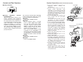
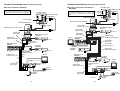
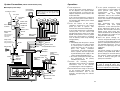
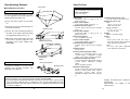
Multi Control Hub
Model AW-
POWER
OFF
ON
Multi C
ontrol H
ub AW–
Before attempting to connect, operate or adjust this product, please
read these instructions completely.
P
CAUTION
RISK OF ELECTRIC SHOCK
DO NOT OPEN
CAUTION: TO REDUCE THE RISK OF ELECTRIC SHOCK,
DO NOT REMOVE COVER (OR BACK).
NO USER SERVICEABLE PARTS INSIDE.
REFER TO SERVICING TO QUALIFIED SERVICE PERSONNEL.
The lightning flash with arrowhead symbol, within an equilateral triangle,
is intended to alert the user to the presence of uninsulated “dangerous
voltage” within the product’s enclosure that may be of sufficient
magnitude to constitute a risk of electric shock to persons.
The exclamation point within an equilateral triangle is intended to alert the
user to the presence of important operating and maintenance (service)
instructions in the literature accompanying the appliance.
FCC Note:
This device complies with Part 15 of the FCC Rules. To assure continued
compliance follow the attached installation instructions and do not make any
unauthorized modifications.
CAUTION:
Do not install or place this unit in a bookcase, built-in cabinet or any
other confined space in order to maintain adequate ventilation. Ensure
that curtains and any other materials do not obstruct the ventilation to
prevent risk of electric shock or fire hazard due to overheating.
WARNING:
TO REDUCE THE RISK OF FIRE OR SHOCK HAZARD, DO NOT
EXPOSE THIS EQUIPMENT TO RAIN OR MOISTURE.
CAUTION:
TO REDUCE THE RISK OF FIRE OR SHOCK HAZARD AND ANNOYING
INTERFERENCE, USE THE RECOMMENDED ACCESSORIES ONLY.
CAUTION:
OKeep the temperature inside the rack to between 14°F to 113°F
(–10°C to 45°C).
This equipment has been tested and found to comply with the limits for a class A
digital device, pursuant to Part 15 of the FCC Rules. These limits are designed to
provide reasonable protection against harmful interference when the equipment is
operated in a commercial environment. This equipment generates, uses, and can
radiate radio frequency energy and, if not installed and used in accordance with the
instruction manual, may cause harmful interference to radio communications.
Operation of this equipment in a residential area is likely to cause harmful
interference in which case the user will be required to correct the interference at his
own expense.
indicates safety information.
indicates safety information.
2
3
Table of Contents
For Your Safety
Overview . . . . . . . . . . . . . . . . . . . . . . . . . 4
System Connections . . . . . . . . . . . . . . 11
Accessories . . . . . . . . . . . . . . . . . . . . . . 4
Operations. . . . . . . . . . . . . . . . . . . . . . . 17
For Your Safety. . . . . . . . . . . . . . . . . . . . 5
Rack Mounting Example . . . . . . . . . . . 18
Controls and Their Functions . . . . . . . . 6
$ Rack Mounting Procedure . . . . . . . 18
$ Front Panel. . . . . . . . . . . . . . . . . . . . 6
$ Rear Panel . . . . . . . . . . . . . . . . . . . . 7
Specifications . . . . . . . . . . . . . . . . . . . . 19
O Use the dedicated AC adapter (AW-PS505) to supply power to the multi control hub.
O Handle with care.
The multi control hub may malfunction if it is dropped or exposed to strong shocks.
O Use within a temperature range of 14°F to 113°F (–10°C to +45°C).
Using the multi control hub in environments colder than 14°F (–10°C) or hotter than
113°F (+45°C) could have a damaging effect on the internal components.
O Connect and disconnect cables only when the power is turned off.
Make sure to turn the power to the multi control hub off before connecting or
disconnecting cables.
$ Priority Switchbox. . . . . . . . . . . . . . 10
O Avoid using the multi control hub outdoors.
O Place the multi control hub a minimum of 1 meter away from monitor video screens.
Overview
O The AW-HB605 multi control hub combines with a system such as the Panasonic AWPH300 series indoor pan/tilt head or AW-PH600 series outdoor pan/tilt head to support
the connection of between one and five control panels (AW-RP501, AW-RP301, AWRP305) to a single camera and pan/tilt head. Any of the connected control panels may
then be used to control the camera and pan/tilt head (the AW-RP301 and AW-RP305
can control the pan/tilt head only).
In addition, by adding the AW-HB505 multi port hub and AW-RP505 multi hybrid control
panel, it is possible to construct a system in which between one and five multi hybrid
control panels may be used to control between one and five cameras and pan/tilt heads.
O When coaxial cable/s (5C-2V) and 10BASE-T (UTP category 5) straight cable/s
(10BASE-T cable only for the AW-RP301 and AW-RP305) are used to make
connections, the distance between the cameras and pan/tilt heads and the control
panels can be extended up to a maximum of 500 meters.
O Cleaning
Unplug the multi control hub and wipe it clean using a dry cloth. For dirt that cannot be
removed in this manner, moisten a cloth with kitchen detergent, wring it out thoroughly,
and then wipe gently.
• Never use volatile chemicals such as benzene or paint thinner to clean the multi
control hub.
• Before using chemically treated cloths to clean the multi control hub, read their
instructions and precautions thoroughly.
Accessories
O Priority switchboxes: 5
O Rack mounting brackets: 12
O Mounting screws: 24
4
5
Controls and Their Functions
Controls and Their Functions
$ Front Panel
$ Rear Panel
8
1
9
5 4
PREVIEW OUT
TO CONTROL PANEL
PREVIEW OUT
PAN/TILT
CONTROL IN
PREVIEW OUT
PAN/TILT
CONTROL IN
PREVIEW OUT
PAN/TILT
CONTROL IN
TO PAN/TILT HEAD HUB
PREVIEW OUT
PAN/TILT
CONTROL IN
PREVIEW IN
PAN/TILT
CONTROL OUT
PAN/TILT
CONTROL IN
BLACK
BURST
OUT
POWER
OFF
CAM CONT IN
ON
CAM CONT IN
CAM CONT IN
BLACK
BURST OUT
BLACK
BURST OUT
CAM CONT IN
BLACK
BURST OUT
CAM CONT IN
BLACK
BURST OUT
-
+
BLACK
BURST OUT
CAM CONT OUT
Multi Control Hub AW–
5
4
3
2
1
DC12V IN
2
2 Power Switch [POWER ON/OFF]
Placing this switch at the ON position
when the AC adapter is connected and
turned on supplies power to the multi
control hub (power indicator LED lights).
Placing it at the OFF position cuts off
the power.
<Note>
This switch must be at the ON position
in order to control the camera and
pan/tilt head from each control panel.
1 Power Indicator LED [POWER]
This indicator lights (red) when the
power switch 2 is at the ON position. It
is dark when the power switch 2 is at
the OFF position.
6
7
:
6
3
;
5 Preview
Video
Signal
Input
Connector [TO PAN/TILT HEAD HUB
PREVIEW IN] (BNC Connector)
Connect this connector to the video
signal output connector [VIDEO OUT] of
the pan/tilt head, or to the preview video
signal output connector [TO CONTROL
PANEL PREVIEW OUT] of the multi
port hub using a coaxial cable (5C-2V
equivalent).
<Note>
In a system incorporating the AWRP301 or AW-RP305, the control panel
is not equipped with a video signal cable
compensation circuit. It may therefore
be necessary to use a separate cable
compensation device in some cases.
3 DC +12 V Input Connector [DC12 V IN]
(4-pin Cannon Connector)
Connect the AW-PS505 AC adapter
(sold separately) to this connector.
4 Pan/Tilt Head Control Signal Output
Connector [TO PAN/TILT HEAD HUB
PAN/TILT CONTROL OUT] (RJ-45 8pin Modular Jack)
Connect this connector to the control
signal input connector [P/T CONTROL
IN] of the AW-PH300 or AW-PH600
pan/tilt head, or to the pan/tilt control
signal input connector [TO CONTROL
PANEL PAN/TILT CONTROL IN] of the
AW-HB505 multi port hub using a
10BASE-T (UTP category 5) straight
cable.
7
Controls and Their Functions
Controls and Their Functions
8 Pan/Tilt Head Control Signal Input
Connector [TO CONTROL PANEL
PAN/TILT CONTROL IN] (RJ-45 8-pin
Modular Jack)
Connect this connector to the control
panel pan/tilt control signal output
connector [PAN/TILT CONTROL OUT]
of the control panel using a 10BASE-T
(UTP category 5) straight cable.
6 Black Burst Output [TO PAN/TILT
HEAD HUB BLACK BURST OUT]
(BNC Connector)
This is the output jack for the reference
signal generator built into the multi
control hub. This signal may be used as
the reference signal if the camera uses
external synchronization.
Connect this connector to the G/L signal
input connector [G/L IN] of the pan/tilt
head, or to the G/L signal input
connector [TO CONTROL PANEL G/L
IN] of the multi port hub using a coaxial
cable (5C-2V equivalent).
9 Preview
Video
Signal
Output
Connector [TO CONTROL PANEL
PREVIEW OUT] (BNC Connector)
Connect this connector to the video
input
connector
[TO
CAMERA
PAN/TILT HEAD VIDEO IN] of the
hybrid control panel (AW-RP501), or to
the preview video input connector
[PREVIEW IN] of the multi hybrid control
panel (AW-RP505) using a coaxial cable
(5C-2V equivalent).
If the system incorporates a pan/tilt
control panel (AW-RP301) or multi
pan/tilt control panel (AW-RP305), the
control panel is not equipped with a
video input connector. If necessary, the
output from the preview video signal
output connector may be connected to a
monitor video screen, VCR, or the like
via a cable compensation device.
7 Camera Control Output Connector
[TO PAN/TILT HEAD HUB CAM CONT
OUT] (BNC Connector)
Connect this connector to the camera
control signal input connector [CAMERA
CONTROL IN] of the pan/tilt head, or to
the camera control signal input
connector [TO CONTROL PANEL
CAMERA CONTROL IN] of the multi
port hub using a coaxial cable (5C-2V
equivalent).
8
: Camera
Control
Signal
Input
Connector [TO CONTROL PANEL
CAM CONT IN] (BNC Connector)
Connect this connector to the camera
control signal output connector [TO
CAMERA PAN/TILT HEAD CAMERA
CONTROL OUT] of the hybrid control
panel (AW-RP501), or to the camera
control signal output connector [TO
CAMERA PAN/TILT HEAD CAMERA
CONTROL OUT] of the multi hybrid
control panel (AW-RP505) using a
coaxial cable (5C-2V equivalent).
If the system incorporates a pan/tilt
control panel (AW-RP301) or multi
pan/tilt control panel (AW-RP305), the
control panel is not equipped with a
camera control output connector. In this
case, this connector should be left
unconnected.
; Black Burst Output [BLACK BURST
OUT] (BNC Connector)
This is the output jack for the reference
signal generator built into the multi
control hub. This signal may be used as
the reference signal for peripheral
equipment
that
uses
external
synchronization.
9
Controls and Their Functions
System Connections (Indoor Pan/tilt Head System)
$ Priority Switchbox
O Turn off the power to all pieces of
equipment
before
making
any
connections.
O For the control panel, use the AC
adapter model AW-PS301 (sold
separately), for the multi port hub and
multi control hub, the AC adapter model
AW-PS505 (sold separately), and for the
pan/tilt head AC adapter model, the AWPS300 (sold separately).
O Use an AW-PH300 series pan/tilt head
and a camera from the convertible
camera series.
Use camera cable AW-CA50 T15 (sold
separately) to make connections
between the pan/tilt head and camera.
O Connect the pan/tilt head (AW-PH300)
to its AC adapter (AW-PS300) using a
DC power cord (cable conforming to the
Electrical Equipment Handling Law and
with a nominal cross-sectional area of
1.25 mm2 or more, to be obtained
locally). The maximum cable distance
between the pan/tilt head and its AC
adapter is 30 meters.
O Connect the multi control hub to its AC
adapter (AW-PS505).
O Connect the multi port hub to its AC
adapter (AW-PS505).
O Connect the control panel (AW-RP301,
AW-RP305, AW-RP501, AW-RP505) to
its AC adapter (AW-PS301). Use a cord
clamper to secure the DC cord of the
AC adapter and prevent the DC plug
from coming loose accidentally.
O Connect the pan/tilt head and the
convertible camera using the AW-CA50
T15 camera cable.
O Connect the electric zoom lens iris
control cable to the camera and the
remote (zoom and focus control) cable
to the pan/tilt head.
<
The connection terminals differ depending
on the control panel model. The correct
connection terminals are listed below.
AW-RP301:
TALLY HOT and GND terminals.
AW-RP305:
Any of terminals TALLY 1 through
TALLY 5 and the GND terminal. (Make
sure that the pan/tilt head control
connector number to which the AWHB605 is connected and the TALLY
terminal number to which the priority
switchbox is connected match.)
Also, if the pan/tilt head is being
controlled via the AW-HB605, it is
necessary to select the number to which
the AW-HB605 is connected using the
pan/tilt head selector switch of the AWRP305.
AW-RP501:
TALLY HOT and GND terminals.
AW-RP505:
TALLY 5 and GND terminals.
< Priority
Switchbox
Contacts
(Terminal Panel)
These are the output contacts of the
priority switchbox. They should be
connected to the TALLY terminals on
the control panel. These terminals are
not polarized. Make connections using
cable conforming to the Electrical
Equipment Handling Law and with a
nominal cross-sectional area of 0.128
mm2 (wire number AWG26) or more.
The maximum cable length (distance
between priority switchbox and control
panel) is 10 meters.
10
Cord clamper
DC cord
Control panel AC adapter:
AW-PS301
Iris control cable
Remote (zoom/focus
control) cable
To iris connector
To lens interface
connector
11
System Connections (Indoor Pan/tilt Head System)
System Connections (Indoor Pan/tilt Head System)
$ System Incorporating AW-RP301
<Note>
Since the pan/tilt control panel is not equipped with a video signal compensation circuit, it
may be necessary to use a separate cable compensation device in some cases.
$ System Incorporating AW-RP305
<Note>
Since the multi pan/tilt control panel is not equipped with a video signal compensation
circuit, it may be necessary to use a separate cable compensation device in some cases.
Maximum Cable Length
The maximum cable length from the camera and
pan/tilt head to the pan/tilt control panel is 500 meters.
Maximum Cable Length
The maximum cable length from the camera and
pan/tilt head to the multi pan/tilt control panel is 500
meters.
Convertible camera
OPT CN CARD
VIDEO OUT
LF REMCTE
MENU
TEM AWC
Iris control cable
GL N
Pan/tilt head cable:
AW-CA50T15
Convertible camera
OPT CN CARD
LF REMCTE
TEM AWC
YES ABC
Iris control cable
IRIS
IRIS
DC12V IN
Pan/tilt head: AW-PH300
Pan/tilt head: AW-PH300
Camera mounting
adapter
Camera mounting
adapter
Remote (zoom/focus control) cable
Remote (zoom/focus control) cable
Pan/tilt head AC adapter:
AW-PS300
Pan/tilt head AC adapter:
AW-PS300
Coaxial cable:
Video signal
O I
O I
PREVIEW OUT
TO CONTROL PANEL
PREVIEW OUT
PAN/TILT
CONTROL IN
CAM CONT IN
PREVIEW OUT
PAN/TILT
CONTROL IN
CAM CONT IN
10BASE-T cable:
Pan/tilt head control
signal
BLACK
BURST OUT
PREVIEW OUT
PAN/TILT
CONTROL IN
BLACK
BURST OUT
BLACK
BURST OUT
PREVIEW IN
PAN/TILT
CONTROL OUT
PAN/TILT
CONTROL IN
BLACK
BURST
OUT
CAM CONT IN
BLACK
BURST OUT
AC 120 V
Multi control hub:
AW-HB605
AC adapter:
AW-PS505
TO PAN/TILT HEAD HUB
PREVIEW OUT
PAN/TILT
CONTROL IN
CAM CONT IN
CAM CONT IN
-
PREVIEW OUT
TO CONTROL PANEL
PREVIEW OUT
PAN/TILT
CONTROL IN
PREVIEW OUT
PAN/TILT
CONTROL IN
PREVIEW OUT
PAN/TILT
CONTROL IN
CAM CONT IN
CAM CONT IN
BLACK
BURST OUT
CAM CONT IN
CAM CONT IN
4
3
2
BLACK
BURST OUT
BLACK
BURST OUT
BLACK
BURST OUT
AC 120 V
10BASE-T cable:
Pan/tilt head control
signal
AC adapter:
AW-PS505
PAN/TILT
CONTROL OUT
BLACK
BURST
OUT
-
+
BLACK
BURST OUT
O I
O I
CAM CONT OUT
5
1
4
3
2
1
DC12V IN
DC12V IN
10BASE-T Cable:
Pan/tilt head control
signal
10BASE-T cable:
Pan/tilt head control
signal
AC 120 V
Pan/tilt control panel:
AW-RP301
Monitor
PREVIEW IN
PAN/TILT
CONTROL IN
CAM CONT IN
CAM CONT OUT
5
TO PAN/TILT HEAD HUB
PREVIEW OUT
PAN/TILT
CONTROL IN
+
BLACK
BURST OUT
Pan/tilt head cable:
AW-CA50T15
YES ABC
DC12V IN
Multi control hub:
AW-HB605
GL N
NO BAR
NO BAR
Coaxial cable:
Video Signal
VIDEO OUT
MENU
Multi pan/tilt control panel:
AW-RP305
Priority
switchbox
AC adapter:
AW-PS301
AC 120 V
Monitor
Priority
switchbox
AC adapter:
AW-PS301
AC 120 V
12
AC 120 V
13
System Connections (Indoor Pan/tilt Head System)
System Connections (Indoor Pan/tilt Head System)
$ System Incorporating AW-RP501
$ System Incorporating AW-RP505 or
AW-HB505
Convertible camera
OPT CN CARD
VIDEO OUT
LF REMCTE
Maximum Cable Length
The maximum cable length from the camera and
pan/tilt head to the hybrid control panel is 500 meters.
MENU
Convertible camera
OPT CN CARD
VIDEO OUT
Pan/tilt head cable:
AW-CA50T15
LF REMCTE
MENU
TEM AWC
GL N
Maximum Cable Length
The maximum cable length from the camera and
pan/tilt head to the multi hybrid control panel is 500
meters.
Iris control
cable
TEM AWC
GL N
Pan/tilt head cable:
AW-CA50T15
YES ABC
IRIS
NO BAR
DC12V IN
Pan/tilt head: AW-PH300
YES ABC
IRIS
Iris control cable
NO BAR
Camera mounting
adapter
DC12V IN
Remote (zoom/focus control) cable
Pan/tilt head: AW-PH300
Camera mounting
adapter
Coaxial cable:
Camera control signal
Pan/tilt head AC adapter:
AW-PS300
Remote (zoom/focus control) cable
Coaxial cable:
Gen-lock signal
Coaxial cable:
Video Signal
O I
AC 120 V
Coaxial cable:
Video signal
Pan/tilt head AC adapter:
AW-PS300
Coaxial cable:
Camera control signal
O I
Monitor
10BASE-T cable:
Pan/tilt head control signal
Multi port hub:
AW-HB505
AC 120 V
Multi Control Hub:
AW-HB605
PREVIEW OUT
TO CONTROL PANEL
PREVIEW OUT
PAN/TILT
CONTROL IN
CAM CONT IN
PREVIEW OUT
PAN/TILT
CONTROL IN
CAM CONT IN
BLACK
BURST OUT
PREVIEW OUT
PAN/TILT
CONTROL IN
BLACK
BURST OUT
PREVIEW OUT
PAN/TILT
CONTROL IN
CAM CONT IN
CAM CONT IN
TO PAN/TILT HEAD HUB
BLACK
BURST OUT
PREVIEW IN
PAN/TILT
CONTROL OUT
PAN/TILT
CONTROL IN
BLACK
BURST
OUT
CAM CONT IN
BLACK
BURST OUT
10BASE-T cable:
Pan/tilt head control
signal
AC adapter:
AW-PS505
-
Coaxial cable:
Gen-lock signal
S-Video
+
BLACK
BURST OUT
AC adapter:
AW-PS505
O I
CAM CONT OUT
5
4
3
2
Coaxial cable:
Camera control signal
1
Coaxial cable:
Video signal
DC12V IN
AC 120 V
10BASE-T cable:
Pan/tilt head control
signal
Monitor
Coaxial cable:
Camera control signal
O I
AC 120 V
Multi control hub:
AW-HB605
PREVIEW OUT
TO CONTROL PANEL
PREVIEW OUT
PAN/TILT
CONTROL IN
CAM CONT IN
PREVIEW OUT
PAN/TILT
CONTROL IN
CAM CONT IN
CAM CONT IN
BLACK
BURST OUT
PREVIEW OUT
PAN/TILT
CONTROL IN
BLACK
BURST OUT
CAM CONT IN
BLACK
BURST OUT
PREVIEW IN
PAN/TILT
CONTROL IN
PAN/TILT
CONTROL OUT
BLACK
BURST
OUT
CAM CONT IN
BLACK
BURST OUT
AC adapter:
AW-PS505
TO PAN/TILT HEAD HUB
PREVIEW OUT
PAN/TILT
CONTROL IN
-
+
BLACK
BURST OUT
O I
Preview
monitor
CAM CONT OUT
S-Video
5
Hybrid control panel:
AW-RP501
Coaxial cable:
Video signal
4
3
2
Coaxial cable:
Camera control signal
1
DC12V IN
10BASE-T cable:
Pan/tilt head control
signal
Priority
switchbox
AC adapter:
AW-PS301
Multi hybrid control
panel:
AW-RP505
Coaxial cable:
Video signal
Priority
switchbox
AC 120 V
AC 120 V
14
AC 120 V
15
AC adapter:
AW-PS301
System Connections (Indoor Pan/tilt Head System)
Operations
$ Example System Setup
1. Turn the power on.
Color monitor
(75 Ω terminator)
Zoom/focus control
Adjustment such as cable compensation, genlock adjustment, and total pedestal adjustment
should be applied to the video signals output
from the AW-HB505.
Iris control
Convertible
camera
Video
S-Video
Camera cable:
AW-CA50T15
Servo control
zoom lens
Camera control
Gen-lock
Video
Multi port hub:
AW-HB505
AC adapter:
AW-PS505
1
CABLE
2
3
COMP
4
5
POWER
OFF
ON
Y
C
Y
C
Y
C
Y
C
Y
O I
C
Multl
Lamp control:
Unnecessary if no
halogen lamp is used.
Port
Hub
AW-H8505
Preview Video
DC15V
Gen-lock
Camera control
O I
POWER
OFF
Contact
Pan/tilt head control
Multi control hub:
AW-HB605
Halogen lamp
the system incorporates a hybrid
control panel or multi hybrid control
panel, perform video signal cable
compensation,
G/L
(gen-lock)
adjustment,
and
total
pedestal
adjustment. Also set the switches as
appropriate. For detailed instructions,
refer to the manuals accompanying the
relevant equipment.
<Note>
After performing G/L (gen-lock)
adjustment
and
total
pedestal
adjustment, set the control panel’s G/L
phase adjustment switch to the OFF
position. The instruction manual of the
hybrid control panel states that this
switch should be left in the ON position,
but it should be set to OFF on systems
using the multi control hub.
2. Press
Pan/tilt head
control
Option switch
control:
Unnecessary if no
optional unit is
connected.
5. If
Turn on the power control switches of
the AC adapters of the pan/tilt heads
and control panels, as well as the AC
adapter and power control switch of the
multi control hub.
If the system incorporates a multi port
hub, turn on the power control switch of
the multi port hub and the power switch
of its AC adapter.
ON
AC adapter:
AW-PS505
Preview Video
Pan/tilt head AC
adapter:
AW-PS300
Preview color
monitor
(75 Ω terminator)
Multi hybrid control
panel:
AW-RP505
Optional unit
the button on the priority
switchbox connected to the control
panel you wish to operate. This
activates the connected control panel.
If the system incorporates a multi hybrid
control panel, use the camera and
pan/tilt head selector switch on the multi
hybrid control panel to select a pan/tilt
head. (The control panel is activated
once its memory switch stops flashing
and goes dark.)
<Notes>
O Immediately after the power is turned
on the system is in a status in which
no control panel is selected. After
turning the power on, do not fail to
press
the
priority
switchbox
connected to the control panel you
wish to operate. After this operation
is performed the power supply to the
camera and pan/tilt head turns on.
O The active control panel is always the
one connected to the priority
switchbox pressed last.
6. Store
the preset settings for the
cameras and pan/tilt heads in memory
(systems incorporating hybrid control
panel or multi hybrid control panel only).
For detailed instructions, refer to the
manuals accompanying the relevant
equipment.
<Note>
The preset settings are stored in the
memory of the pan/tilt head. When new
preset settings are stored in memory, all
the previous settings (including those
stored in memory using the control
panel) are overwritten.
3. Perform
Priority
switchbox
the
mounting
balance
adjustment on the cameras. For detailed
instructions, refer to the manuals
accompanying the relevant equipment.
The adjustments and settings described
in steps
though
above may be
omitted if no changes need to be made to
the current adjustments and settings.
3
4. Set the limits to the range of movement
AC adapter:
AW-PS301
Camera control
for the pan/tilt head (limiter). For
detailed instructions, refer to the
manuals accompanying the relevant
equipment.
Pan/tilt head control
Preview Video
16
17
6
Rack Mounting Example
Specifications
Power switch
$ Rack Mounting Procedure
Power supply:
DC +12 V (4-pin Cannon Connector)
Power consumption:
DC 12 V, 0.47 A
Multi Control Hub
To mount the multi control hub on a rack,
use the supplied rack mounting brackets
and mounting screws (M4a10).
1 Press the power switch to turn power
off.
2 Remove the four feet from the bottom of
the multi control hub.
Feet
Mounting screws
3 Secure the rack mounting brackets to
the sides of the multi control hub using
the supplied mounting screws (a4).
4 Mount the multi control hub in the rack
and secure it in place using four rack
mounting screws (part number W2MSS/5008).
Rack mounting bracket
Rack mounting screws
W2-MSS/5008
(Option)
Rack mounting bracket
Switchbox
To mount the switchbox on a rack, use the
supplied rack mounting brackets and
mounting screws (M4a8).
Mounting screws
<Notes>
O Rack mounting screws sold separately (part number W2-MSS/5008).
O To ensure that the temperature within the rack does not exceed +113°F (+45°C), make
sure to provide sufficient space (a minimum of one chassis width between units)
between the multi control hub and the other pieces of equipment mounted in the rack
or install a cooling fan.
18
Operating temperature range:
+14°F to +113°F (–10°C to +45°C)
Dimensions (WaHaD):
Body:
16 9/16˝a3 1/2˝a9 7/8˝
(420a88a250 mm)
Priority switchbox:
2 13/16˝a3 1/2˝a1 7/16˝
(70a88a35 mm)
Weight:
Approx. 12.32 lb (5.6 kg)
Finish:
Cover:
Steel panel with AV ivory color
polyvinyl chloride finish (approximate
color: Munsell 7.9Y 6.8/0.8)
Panel:
AV ivory color paint (approximate
color: Munsell 7.9Y 6.8/0.8)
Video input:
Composite video 1 V [p-p] 75 Ω a1
(BNC connector)
Camera control inputs:
Control signal (BNC connector) a5
Pan/tilt head control inputs:
Control signal (RJ-45 8-pin modular
jack) a5
Preview video outputs:
Composite video 1 V [p-p] 75 Ω a5
(BNC connector)
Black burst outputs:
75 Ω a6 (BNC connector)
Camera control output:
Control signal (BNC connector)
Pan/tilt head control output:
Control signal (RJ-45 8-pin modular
jack)
Switch function:
Power on/off
Control panel connecting cables:
Number of connecting cables: 4 (3
coaxial cables, 1 10BASE-T straight
cable); 5 sets (when using G/L function)
Pan/tilt head connecting cables:
4 connecting cables per pan/tilt head (3
coaxial cables, 10BASE-T straight
cable)
(when using G/L function)
Maximum cable length:
Length of cable from camera and pan/tilt
head to control panel: Max. 500 m
(assuming: coaxial cable: 5C-2V,
10BASE-T straight cable: UTP category
5)
Weight and dimensions indicated are
approximate.
Specifications are subject to change
without notice.
19
PANASONIC BROADCAST & DIGITAL SYSTEMS COMPANY
DIVISION OF MATSUSHITA ELECTRIC CORPORATION OF AMERICA
Executive Office:
3330 Cahuenga Blvd W., Los Angeles, CA 90068 (323) 436-3500
EASTERN ZONE:
One Panasonic Way 4E-7, Secaucus, NJ 07094 (201) 348-7621
Mid-Atlantic/New England:
One Panasonic Way 4E-7, Secaucus, NJ 07094 (201) 348-7621
Southeast Region:
1225 Northbrook Parkway, Ste 1-160, Suwanee, GA 30024 (770) 338-6835
Central Region:
1707 N Randall Road E1-C-1, Elgin, IL 60123 (847) 468-5200
WESTERN ZONE:
3330 Cahuenga Blvd W., Los Angeles, CA 90068 (323) 436-3500
Dallas Region:
6226 Abington Way, Houston, TX 77008 (713) 802-2726
No. CA/Northwest Region:
5870 Stoneridge, #3, Pleasanton, CA 94588 (925) 416-5108
Government Marketing Department:
52 West Gude Drive, Rockville, MD 20850 (301) 738-3840
Panasonic Canada Inc.
5770 Ambler Drive, Mississauga, Ontario L4W 2T3 (905) 624-5010
Panasonic Sales Company
Division of Matsushita Electric of Puerto Rico Inc.
San Gabriel Industrial Park, 65th Infantry Ave., Km. 9.5, Carolina, Puerto Rico 00630 (787) 750-4300
Printed in Japan
7J1A463A
F0700W @
P