1
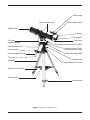
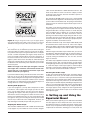
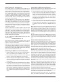
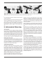
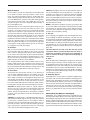
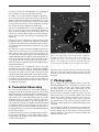
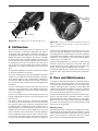
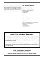
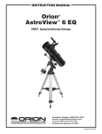
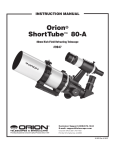
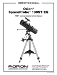
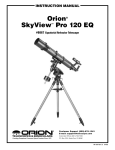
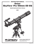
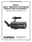
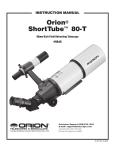
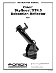
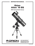
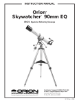
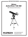
instruction Manual
Orion
AstroView 100 EQ™
®
#9862 100mm Equatorial Refracting Telescope
Customer Support (800)‑676-1343
E-mail: [email protected]
Corporate Offices (831)‑763-7000
Providing Exceptional Consumer Optical Products Since 1975
89 Hangar Way, Watsonville, CA 95076
IN 191 Rev. B 02/09
Finder scope
Tube mounting rings
Finder scope bracket
Objective lens
Eyepiece
Star diagonal
Tube ring
attachment knobs
Counterweight shaft
Focus knob
Declination slow-motion control cable
Right Ascension (R.A.)
slow-motion control cable
Counterweight
Polar axis finder scope
Counterweight lock knob
“Toe saver”
Latitude scale
Tripod leg
Latitude adjustment T-bolts
Accessory tray bracket
Accessory tray
Leg lock knob
Figure 1. The AstroView 100 EQ Reflector.
2
Welcome to the exciting world of amateur astronomy! Your new AstroView 100 EQ Reflector is designed
for high-resolution viewing of astronomical objects. With its precision optics and equatorial mount, you’ll
be able to locate and enjoy hundreds of fascinating celestial denizens, including the planets, Moon, and
a variety of deep-sky galaxies, nebulas, and star clusters.
These instructions will help you set up, properly use, and care for your telescope. Please read them thoroughly before getting started.
Table of Contents
2. Assembly
1. Parts list . . . . . . . . . . . . . . . . . . . . . . . . . . 3
2. Assembly . . . . . . . . . . . . . . . . . . . . . . . . . 3
3. Getting Started . . . . . . . . . . . . . . . . . . . . 5
4.Setting up and Using the
Equatorial Mount . . . . . . . . . . . . . . . . . . . 7
Make sure all the parts listed in the Parts List are present and
familiarize yourself with their features. Please keep the original shipping box and interior packaging. In the unlikely event
that you should need to ship the original telescope back to
Orion, you should use the original packaging.
5. Astronomical Observing . . . . . . . . . . . . 11
6. Terrestrial Observing . . . . . . . . . . . . . . . 14
7. Photography . . . . . . . . . . . . . . . . . . . . . . 15
8. Collimation . . . . . . . . . . . . . . . . . . . . . . . 15
9. Care and maintenance . . . . . . . . . . . . . 16
10. Specifications . . . . . . . . . . . . . . . . . . . . . 16
1. Parts List
1
Optical tube assembly
1
German equatorial mount
1
Counterweight shaft
1
Counterweight
3
Tripod legs with attached accessory tray bracket
3
Leg attachment screws with wingnuts and washers
3
Leg lock knobs
1
Accessory tray with mounting hardware
2
Slow-motion control cables
1
Polar axis finder scope
1
Plastic cover for polar axis
2
Tube mounting rings
2
Tube ring attachment knobs with washers
1
6x30 Achromatic crosshair finder scope
1
Finder scope bracket with O-ring
1
90° Star diagonal
1
25mm Sirius Plössl eyepiece
1
10mm Sirius Plössl eyepiece
1
Dust cap
1
Collimation tool
Assembling the telescope for the first time should take about
30 minutes. No tools are needed other than the ones provided.
All screws should be tightened securely to eliminate flexing
and wobbling, but be careful not to over-tighten or the threads
may strip. Refer to Figure 1 during the assembly process.
During assembly (and anytime, for that matter), do not touch
the surfaces of the telescope objective lens, the lenses of the
finder scope, or eyepiece lenses with your fingers. The optical
surfaces have delicate coatings on them that can easily be
damaged if touched inappropriately.
1. Lay the equatorial mount on its side. Attach the tripod
legs one at a time to the mount using the leg attachment
screws. line up the holes in the top of the tripod leg with
the holes in the base of the mount, and install the screw so
it passes through the leg and the mount with one washer
on both sides of the tripod leg. Tighten the wingnuts only
finger-tight, for now.
2. Insert and tighten the leg lock knobs into the base of the
tripod legs. For now, keep the legs at their shortest (fully
retracted) length; you can extend them to a more desirable
length later, after the scope is completely assembled.
3. Stand the tripod upright and spread the tripod legs apart
as far as they will go, until the accessory tray bracket is
taut. Attach the accessory tray to the bracket with the
three wingnut screws already installed in the tray. Push the
screws up through the holes in the bracket, then thread
them into the holes in the tray.
4. Next, tighten the wingnuts at the top of the tripod legs, so
the legs are securely fastened to the equatorial mount.
Use the wrench and your fingers to do this.
Warning: Never look directly at the Sun through
your telescope or its finder scope—even for an
instant—without a professionally made solar
filter that completely covers the front of the
instrument, or permanent eye damage could
result. Young children should use this telescope
only with adult supervision.
3
Finder scope bracket
Nylon
thumbscrews
Finder scope
Tensioner
Focusing lock ring
Figure 2b. Pull‑back on the tensioner and slide the finder scope
into its bracket until the O-ring is seated in the bracket ring
Figure 2a. The 6x30 finder scope
Focus lock thumbscrew
5. Orient the equatorial mount as it appears in Figure 1, at
a latitude of about 40°, i.e., so the pointer next to the latitude scale is pointing to the line at “40”. To do this, loosen
one of the latitude adjusting T-bolts and then tighten the
other latitude adjusting T-bolt until the pointer and the “40”
line up. The declination (Dec.) and right ascension (R.A.)
axes many need re-positioning (rotation) as well. Be sure
to loosen the RA and Dec. lock levers before doing this.
Retighten them once the equatorial mount is properly oriented.
Eyepiece
6. Thread the counterweight shaft into the equatorial mount
at the base of the declination axis until tight. Make sure the
casting at the top of the bar is threaded clockwise as far as
it will go before attaching the shaft.
7. Remove the knurled “toe saver” retaining screw on the bottom of the counterweight shaft and slide the counterweight
onto the shaft. Make sure the counterweight lock knob is
adequately loosened so the metal pin inside the counterweight is recessed enough to allow the counterweight shaft
to pass through the hole. Position the counterweight about
halfway up the shaft and tighten the lock knob. Replace
the toe saver on the end of the bar. The toe saver prevents
the counterweight from falling on your foot if the lock knob
happens to come loose.
8. Attach the two tube rings to the equatorial mount using the
mounting ring attachment knobs. Place a lock washer, then
a flat washer, on the shaft of each knob. With the washers
attached, push the knob up through the holes in the top of
the equatorial mount and rethread them into the bottom of
the tube rings. Tighten the knobs securely. Open the tube
rings by loosening the knurled ring clamps.
9. Lay the telescope optical tube in the tube rings. Position
the optical tube in the rings so that the 1/4"-20 mounting
block on the underside of the tube is centered relative to
4
90° star diagonal
Camera T-ring
attachment threads
2" adapter
1.25" adapter
Figure 3. The Focuser of the AstroView 100
the rings. Close the rings over the tube and tighten the
knurled ring clamps finger-tight to secure the telescope.
10.Attach the two slow-motion control cables to the R.A. and
Dec. worm gear shafts of the equatorial mount by positioning the small screw on the end of the cable over the
indented slot on the worm gear shaft. Then tighten the
screw. Use the short slow-motion control for the R.A. axis,
it will stick out sideways from the mount. The longer slowmotion control moves the telescope on its Dec. axis and
goes just under the optical tube, towards the focus wheels.
See Part 4 for more information about the R.A. and declination axes.
11.Install the polar axis finder scope into its housing inside
the R.A. axis of the equatorial mount. First loosen the three
Figure 4a.
Figure 4b.
Proper operation of the equatorial mount requires that the telescope tube be balanced on the R.A. axis. (a) With the R.A. lock lever released,
slide the counterweight along the counterweight shaft until it just counterbalances the tube. (b) When you let go with both hands, the tube
should not drift up or down. The telescope should be balanced in the Dec. axis already if you have properly centered the 1/4"-20 mounting
block on the optical tube relative to the tube rings.
thumbscrews on the housing, which is located at the rear
of the R.A. axis. Insert the front end of the polar finder (the
end without the eyeguard) into the housing so only about
1" of the polar finder extends from the back of the housing.
Do this slowly and with a twisting motion to prevent the
internal O-ring from becoming unseated. If it does become
unseated, you can remove the entire housing from the
mount to locate the O-ring and reseat it. This is done by
rotating the entire housing counterclockwise. Once the
polar axis finder scope is in the housing, tighten the three
thumbscrews. These thumbscrews will be used later to
align the finder with the mount’s R.A. axis.
Installing the Finder Scope
To place the finder scope in the finder scope bracket, first
unthread the two black nylon screws until the screw ends
are flush with the inside diameter of the bracket. Place the
O-ring that comes on the base of the bracket over the body
of the finder scope until it seats into the slot on the middle of
the finder scope. Slide the eyepiece end (narrow end) of the
finder scope into the end of the bracket’s cylinder opposite the
adjustment screws while pulling the chrome, spring-loaded
tensioner on the bracket with your fingers (Figure 2b). Push
the finder scope through the bracket until the O-ring seats just
inside the front opening of the bracket cylinder. Now, release
the tensioner and tighten the two black nylon screws a couple
of turns each to secure the finder scope in place. Insert the
base of the finder scope bracket into the dovetail slot on the
top of the focuser. Lock the bracket into position by tightening
the knurled thumbscrew on the dovetail slot.
Inserting the Eyepiece
Loosen the thumbscrew on the 1.25" eyepiece adapter (Figure
3) and insert the chrome barrel of the star diagonal into the
adapter. Then, loosen the thumbscrews on the star diagonal
and remove the small dust cap. Then insert the 25mm Sirius
Plössl eyepiece into the focuser and secure it with the thumbscrews.
Your telescope is now completely assembled and should
appear as shown in Figure 1.
3. Getting Started
Balancing the Telescope
To ensure smooth movement of the telescope on both axes
of the equatorial mount, it is imperative that the optical tube
is properly balanced. We will first balance the telescope with
respect to the R.A. axis.
1. Keeping one hand on the telescope optical tube, loosen
the R.A. lock lever. Make sure the Dec. lock lever is locked,
for now. The telescope should now be able to rotate freely
about the R.A. axis. Rotate it until the counterweight shaft
is parallel to the ground (i.e., horizontal).
2. Now loosen the counterweight lock knob and slide the
weight along the shaft until it exactly counterbalances the
telescope (Figure 4a). That’s the point at which the shaft
remains horizontal even when you let go with both hands
(Figure 4b).
3. Retighten the counterweight lock knob. The telescope is
now balanced on the R.A. axis.
The telescope should be balanced in the Dec. axis already if
you have properly centered the 1/4"-20 mounting block on the
optical tube relative to the tube rings.
Now when you loosen the lock lever on one or both axes and
manually point the telescope, it should move without resistance and should not drift from where you point it.
5
cation and the 30 indicates a 30mm diameter front lens. The
finder scope makes it easier to locate the subject you want
to observe in the telescope, because the finder scope has a
much wider field of view.
View through finder scope
View through the AstroView 100 EQ
Figure 5. Images through the finder scope will appear upsidedown and backwards (rotated 180°). Images through the AstroView
100 EQ with its diagonal in place will be reversed from left-to right.
Focusing the Telescope
You should now try to familiarize yourself with focusing the
telescope. With the 25mm eyepiece inserted in the diagonal, point the telescope in the general direction of an object
at least a 1/4 mile away. With your fingers, slowly rotate one
of the focus knobs until the object comes into sharp focus. If
the focuser motion is stiff, loosen the focus lock thumb screw
(Figure 3) until it moves more smoothly. Go a little bit beyond
sharp focus until the object starts to blur again, then reverse
the direction of the focus knob, just to make sure you’ve hit the
exact focus point.
NOTE: The image in the telescope will appear reversed
left-to-right. This is normal for astronomical refractor telescopes that use a star diagonal. The finder scope view
will be rotated 180° (see Figure 5).
If you have trouble focusing, rotate the focus knob so the drawtube is in as far as it will go. Now look through the eyepiece
while slowly rotating the focusing knob in the opposite direction. You should soon see the point at which focus is reached.
You will have to re-adjust the focus when aiming at subjects of
varying distances, or after changing eyepieces.
Viewing with Eyeglasses
If you wear eyeglasses, you may able to keep them on while
you observe, if the eyepiece has enough “eye relief” to allow
you to see the whole field of view. You can try this by looking through the eyepiece first with your glasses on, and then
with them off, and see if the glasses restrict the view to only a
portion of the full field. If they do, you can easily observe with
your glasses off by just re-focusing the telescope the needed
amount. If you suffer from severe astigmatism, however, you
may find images noticeably sharper with your glasses on.
Aligning the Finder Scope
The AstroView 100 EQ comes with a 6x30 achromatic finder
scope (Figure 2a). The number 6 means six-times magnifi6
The AstroView 100 EQ’s finder scope uses a spring-loaded
bracket that makes alignment of the finderscope very easy. As
you turn either of the thumbscrews, the spring in the bracket’s
tensioner moves in and out to keep the finder scope secure in
the bracket.
The finder scope must be aligned accurately with the telescope for proper use. To align it, first aim the main telescope in
the general direction of an object at least a 1/4 mile away-the
top of a telephone pole, a chimney, etc. To aim the telescope,
loosen the R.A. and Dec. lock levers and move it until it is
pointing at the desired object. Sight along the tube for easiest aiming. Turn the focus knob until the object is properly
focused. Center the object in the telescope’s eyepiece by turning the R.A. and Dec. slow-motion controls.
Now look in the finder scope. Is the object visible? Ideally it will
be somewhere in the field of view. If not, some coarse adjustment to the finder scope bracket’s alignment thumbscrews will
be needed until the object comes into the finder scope’s field
of view.
With the image in the finder scope’s field of view, you can now
fine-adjust the alignment thumbscrews to center the object on
the intersection of the crosshairs. Adjust the aim of the finder
scope by turning the thumbscrews, one at a time, until the
object is centered.
The finder scope alignment needs to be checked before every
observing session. This can easily be done at night, before
viewing through the telescope. Choose any bright star or planet, center the object in telescope eyepiece, and then adjust
the finder scope bracket’s alignment thumbscrews until the
star or planet is centered on the finder’s crosshairs.
Focusing the finder scope
If, when you look through the finder scope, the images appear
somewhat out of focus, you will need to refocus the finder
scope for your eyes. Loosen the lock ring located behind the
objective lens cell on the body of the finder scope (see Figure
2a). Back the lock ring off by a few turns, for now. Refocus the
finder scope on a distant object by threading the objective lens
cell in or out of the finderscope body. Precise focusing will be
achieved by focusing the finder scope on a bright star. Once
the image appears sharp, retighten the lock ring behind the
objective lens cell. The finder scope’s focus should not need
to be adjusted again.
4. Setting up and Using the
Equatorial Mount
When you look at the night sky, you no doubt have noticed that
the stars appear to move slowly from east to west over time.
That apparent motion is caused by the Earth’s rotation (from
west to east). An equatorial mount (Figure 6) is designed to
compensate for that motion, allowing you to easily “track” the
Right Ascension lock lever
Declination setting circle
Declination lock lever
Front opening
in R.A. axis
tion
Rig
ht A
lina
Azimuth fine
adjustment knobs
Right Ascension setting circle
lock thumbscrew
sce
nsio
na
D ec
Latitude adjustment
T-bolts
axis
Latitude scale
xis
Polar axis finder scope
Right Ascension setting circle
Figure 6. The equaltorial mount of the AstroView 100 EQ.
movement of astronomical objects, thereby keeping them
from drifting out of the telescope’s field of view while you’re
observing.
This is accomplished by slowly rotating the telescope on its
right ascension (R.A.) axis, using only the R.A. slow-motion
cable. But first the R.A. axis of the mount must be aligned
with the Earth’s rotational (polar) axis, a process called polar
alignment.
Polar Alignment
For Northern Hemisphere observers, approximate polar alignment is achieved by pointing the mount’s R.A. axis at the
North Star, or Polaris. It lies within 1° of the north celestial pole
(NCP), which is an extension of the Earth’s rotational axis
out into space. Stars in the Northern Hemisphere appear to
revolve around Polaris.
To find Polaris in the sky, look north and locate the pattern
of the Big Dipper (Figure 7). The two stars at the end of the
“bowl” of the Big Dipper point right to Polaris.
Observers in the Southern Hemisphere aren’t so fortunate to
have a bright star so near the south celestial pole (SCP). The
star Sigma Octantis lies about 1° from the SCP, but it is barely
visible with the naked eye (magnitude 5.5).
For general visual observation, an approximate polar alignment is sufficient:
1. Level the equatorial mount by adjusting the length of the
three tripod legs.
2. Loosen one of the latitude adjusting T-bolts and tighten the
other to tilt the mount until the pointer on the latitude scale
is set at the latitude of your observing site. If you don’t
Little Dipper
(in Ursa Minor)
Big Dipper
(in Ursa Major)
ter
Poin
Stars
N.C.P.
Polaris
Cassiopeia
Figure 7. To find Polaris in the night sky, look north and find the
Big Dipper. Extend an imaginary line from the two “Pointer Stars” in
the bowl of the Big Dipper. Go about five times the distance between
those stars and you’ll reach Polaris, which lies within 1° of the north
celestial pole (NCP).
know your latitude, consult a geographical atlas to find it.
For example, if your latitude is 35° North, set the pointer
to +35. The latitude setting should not have to be adjusted
again unless you move to a different viewing location some
distance away.
3. Loosen the Dec. lock lever and rotate the telescope optical
tube until it is parallel with the R.A. axis. The pointer on the
Dec. setting circle should read 90°. Retighten the Dec. lock
lever.
4. Move the tripod so the telescope tube (and R.A. axis)
points roughly at Polaris. If you cannot see Polaris directly
from your observing site, consult a compass and rotate the
7
Date circle
Azimuth
fine
adjustment
knobs
Ring with
engraved time
meridian indicator
mark
Tripod
attachment
knob
Polar scope
alignment
thumbscrew (3)
R.A. setting circle
lock thumbscrew
Pointer
R.A. setting circle
Meridian
offset scale
Polar scope
housing
Polar axis
finder scope
Figure 8. For polar alignment, position the tripod so that the “N”
Figure 9. The polar axis finder scope installed in the right
label at the base of the mount faces north. The two azimuth fine
adjustment knobs above it are used to make small adjustments to the
mount’s azimuth position.
ascension (R.A.) axis of the mount.
tripod so the telescope points north. There is a label bearing a large “N” at the base of the equatorial mount (Figure
8). It should be facing north.
The equatorial mount is now approximately polar-aligned for
casual observing. More precise polar alignment is required for
astrophotography and for use of the manual setting circles.
We will start by aligning the polar finder rotationally. Refer to
Figure 9.
1. Loosen the large thumbscrew just above the R.A. setting
circle. Rotate the R.A. setting circle until the line above the
“0” on the setting circle lines up with the pointed indicator
that is cast into the mount (located directly below the large
thumbscrew; see Figure 8). Retighten the thumbscrew.
From this point on in your observing session, you should not
make any further adjustments to the latitude of the mount, nor
should you move the tripod. Doing so will undo the polar alignment. The telescope should be moved only about its R.A. and
Dec. axes.
2. Rotate the date circle until the “0” line on the meridian offset scale lines up with the time meridian indicator mark.
The meridian offset scale is printed on the inner circumference of the date circle, and is labeled “E20” to “W20”. The
time meridian indicator mark is an engraved line on the
exterior of the polar finder’s housing. It is on the “ring” of
the housing that is closest to the date circle.
The Polar Axis Finder Scope
A feature of the AstroView 100 EQ is the polar axis finder
scope housed inside the R.A. axis of the equatorial mount (see
Figure 9). When properly aligned and used, it makes accurate
polar alignment quick and easy to do. Alignment of the polar
finder need only be done once, unless it gets bumped or otherwise shifts its position.
3. The R.A. setting circle is labeled in hours, from “0” to “23”
(military time). For Northern Hemisphere observers, refer
to the top numbers on the setting circle. Each small line
represents 10 minutes of R.A. The date circle is labeled
from “1” to “12”, with each number representing a month of
the year (“1” is January, “2” is February, etc.). Each small
line represents a two-day increment.
Remove the cover cap from the front opening in the R.A. axis
of the mount (see Figure 6). Look through the polar finder at
a distant object. Focus the polar finder so that the images and
reticle are sharp by rotating the eyepiece end of the finder.
Notice that the reticle pattern consists of a crosshair with a
circle around the middle. On the circumference of this circle
is a tiny circle; this is where Polaris will be placed for accurate
polar alignment once the finder is properly aligned. Alignment
of the polar finder is best done during the day, before going
out into the field at night.
4. Loosen the R.A. lock lever and rotate the mount about the
R.A. axis until the March 1 indicating mark (the long line
between the “2” and the “3”) on the date circle lines up with
the 4 PM mark (the long line above the “16”) on the R.A.
setting circle. You may find it convenient to remove both the
counterweights and the telescope optical tube to do this.
Aligning the Polar Axis Finder Scope
Aligning the polar axis finder scope so that it will accurately
point at the true north pole is a two-step procedure. First, the
polar finder must be rotated in its housing so that the small
circle in which Polaris will be placed in is in the proper initial
position. Next, the polar axis finder must be adjusted so that it
points directly along the mount’s R.A. axis.
The polar axis finder scope is now properly set in its initial
position. Next, you must align it so that it is exactly parallel to
the mount’s R.A. axis:
8
5. Now, loosen the three thumbscrews on the polar finder
housing and rotate the polar finder so the small circle where
Polaris will be centered is located straight down from the
intersection of the crosshairs. Retighten the thumbscrews.
6. Look through the polar finder at a distant object (during the
day) and center it in the crosshairs. You may need to adjust
the latitude adjustment T-bolts and the tripod position to do
this.
7. Rotate the mount 180° about the R.A. axis. Again, it may
be convenient to remove the counterweights and optical
tube first.
8. Look through the polar finder again. Is the object being
viewed still centered on the crosshairs? If it is, then no further adjustment is necessary. If not, then look through the
polar finder while rotating the mount about the R.A. axis.
You will notice that the object you have previously centered
moves in a circular path. Use the three thumbscrews on
the housing to redirect the crosshairs of the polar finder to
the apparent center of this circular path. Repeat this procedure until the position that the crosshairs point to does not
rotate off-center when the mount is rotated in R.A. Once
this is accomplished, retighten the thumbscrews.
The polar axis finder scope is now ready to be used. When
not in use, replace the plastic protective cover to prevent the
polar finder from getting bumped, which could knock it out of
alignment.
Using the Polar Axis Finder
When using the polar finder in the field at night, you will need
a red flashlight to illuminate the finder’s reticle. Shine the flashlight at an angle into the front opening in the R.A. axis. Do not
shine it directly into the opening, or the light will be too bright,
and you will also obstruct the view of the polar finder. It may
be helpful to have a friend hold the flashlight while you look
through the polar finder.
For most accurate polar alignment, you will need to know the
approximate longitude of your observing site. This information
can be obtained by looking at a local map. Now, figure the
difference between the longitude of your observing site and
the closest standard time meridian. The standard time meridians are 75°, 90°, 105°, and 120° for the 48 continental states
(150° and 165° for Hawaii and Alaska). Choose the standard
time meridian that is closest in value to your local longitude,
and then calculate the difference. If your local longitude has
a value less than the closest standard time meridian, you are
east of the standard time meridian by the calculated amount.
If your local longitude has a value greater than the closest
standard time meridian, you are west of the standard time
meridian by the calculated amount. For example, if you are
in Las Vegas, which has a longitude of 115°, the closest standard time meridian is 120°. The difference between these two
numbers is 5°. Since Las Vegas’ longitude value is less than
the standard time meridian value, you are 5° east of the closest time meridian.
Take your calculated difference from the closest standard time
meridian and rotate the date circle so that the meridian offset scale line that corresponds to your calculated difference
lines up with the engraved time meridian indicator mark on
the polar finder housing. Each line of the meridian offset scale
represents 5° of longitude. Lines to the left of the “0” on the
meridian offset scale indicate east of the closest standard
time meridian, while lines to the right of the “0” indicate west of
the closest standard time meridian.
of the “0” on the meridian offset scale lines up with the time
meridian indicator mark.
Make sure that the “0” mark on the R.A. setting circle lines up
with the pointed indicator cast into the mount, and that the
large thumbscrew just above it is tightened. Now, rotate the
mount about the R.A. axis until the line on the R.A. setting
circle that corresponds to your current local time lines up with
the line on the date circle that indicates the current date. If
you are on daylight savings time, subtract one hour from your
current local time. For example, if it was November 1 at 9 PM,
standard time, you would rotate the telescope in R.A. until the
line above the “21” (9 P.M.) on the R.A. setting circle lines up
with the long line between the “10” and “11” on the date circle.
The long line indicates the first day of the higher numbered
month, i.e. the line between “10” and “11” marks November
1st.
Finally, look through the polar alignment finder scope while
shining a red flashlight at an angle down the front opening
of the R.A. axis, and center Polaris in the small circle. Adjust
the tilt of the altitude up-or-down with the latitude adjustment
T-bolts and use the azimuth fine adjustment knobs (Figure 8)
for final positioning. To do this, you will first need to loosen the
big tripod attachment knob directly underneath the base of the
equatorial mount. The fine adjustment knobs work by loosening one and then tightening the other. When done, retighten
the tripod attachment knob to firmly secure the mount and tripod. If the fine adjustment knobs do not allow the mount to
move far enough to center Polaris, you will need to rotate the
entire tripod left or right to get it within the fine adjustment’s
range.
Once Polaris is centered in the small circle, you are done.
The telescope is now accurately polar aligned, and can be
used for advanced observational applications, such as astrophotography or precise use of the manual setting circles. As
mentioned before, only move the telescope along the R.A.
and Dec. axes; if you move the tripod, or change the tilt of the
equatorial mount, you will need to polar align again.
Remember, accurate polar alignment is not needed for casual
visual observing. Most of the time, approximate polar alignment, as outlined previously, will suffice.
Tracking Celestial Objects
When you observe a celestial object through the telescope,
you’ll see it drift slowly across the field of view. To keep it in
the field, if your equatorial mount is polar-aligned, just turn
the R.A. slow-motion control. The Dec. slow-motion control is
not needed for tracking. Objects will appear to move faster at
higher magnifications, because the field of view is narrower.
Optional Motor Drive
Optional DC motor drive systems can be mounted on the
AstroView 100 EQ’s equatorial mount to provide hands-free
tracking. Objects will then remain stationary in the field of view
without any manual adjustment of the R.A. slow-motion control. A motor drive system is necessary for astrophotography.
Continuing with the prior example of observing in Las Vegas,
you would rotate the date circle so that the first line to the left
9
Understanding the Setting Circles
The setting circles on an equatorial mount enable you to
locate celestial objects by their “celestial coordinates”. Every
object resides in a specific location on the “celestial sphere”.
That location is denoted by two numbers: its right ascension
(R.A.) and declination (Dec.). In the same way, every location
on Earth can be described by its longitude and latitude. R.A.
is similar to longitude on Earth, and Dec. is similar to latitude.
The R.A. and Dec. values for celestial objects can be found in
any star atlas or star catalog.
Finding Objects With the Setting Circles
Now that both setting circles are calibrated, look up in a star
atlas the coordinates of an object you wish to view.
The R.A. setting circle is scaled in hours, from 1 through 24,
with small marks in between representing 10 minute increments (there are 60 minutes in 1 hour of R.A.). The upper
set of numbers apply to viewing in the Northern Hemisphere,
while the numbers below them apply to viewing in the Southern
Hemisphere. The location of the R.A. coordinate indicator
arrow shown in Figure 5.
2. Loosen the R.A. lock lever and rotate the telescope until
the R.A. value from the star atlas matches the reading on
the R.A. setting circle. Remember to use the upper set
of numbers on the R.A. setting circle. Retighten the lock
lever.
The Dec. setting circle is scaled in degrees, with each mark
representing 2° increments. Values of Dec. coordinates range
from +90° to -90°. The 0° mark indicates the celestial equator.
When the telescope is pointed north of the celestial equator,
values of the Dec. setting circle are positive, while when the
telescope is pointed south of the celestial equator, values of
the Dec. setting circle are negative.
So, the coordinates for the Orion Nebula listed in a star atlas
will look like this:
R.A. 5h 35.4m Dec. -5° 27"
That’s 5 hours and 35.4 minutes in right ascension, and -5
degrees and 27 arc-minutes in declination (there are 60 arcminutes in 1 degree of declination).
Before you can use the setting circles to locate objects, the
mount must be well polar aligned, and the R.A. setting circle
must be calibrated. The Dec. setting circle has been calibrated
at the factory, and should read 90° whenever the telescope
optical tube is parallel with the R.A. axis.
Calibrating the Right Ascension Setting Circle
1. Identify a bright star in the sky near the celestial equator
(Dec. = 0°) and look up its coordinates in a star atlas.
2. Loosen the R.A. and Dec. lock levers on the equatorial
mount, so the telescope optical tube can move freely.
3. Point the telescope at the bright star whose coordinates
you know. Lock the R.A. and Dec. lock levers. Center the
star in the telescope’s field of view with the slow-motion
control cables.
4. Loosen the R.A. setting circle lock thumbscrew (see Figure
9); this will allow the setting circle to rotate freely. Rotate
the setting circle until the arrow under the thumbscrew
indicates the R.A. coordinate listed in the star atlas for the
object. Do not retighten the thumbscrew when using the
R.A. setting circles for finding objects; the thumbscrew is
only needed for polar alignment using the polar axis finder
scope.
1. Loosen the Dec. lock lever and rotate the telescope until
the Dec. value from the star atlas matches the reading on
the Dec. setting circle. Remember that values of the Dec.
setting circle are positive when the telescope is pointing
north of the celestial equator (Dec. = 0°), and negative
when the telescope is pointing south of the celestial equator. Retighten the lock lever.
Most setting circles are not accurate enough to put an object
dead-center in the telescope’s eyepiece, but they should
place the object somewhere within the field of view of the finder scope, assuming the equatorial mount is accurately polar
aligned. Use the slow-motion controls to center the object in
the finder scope, and it should appear in the telescope’s field
of view.
The R.A. setting circle must be re-calibrated every time you
wish to locate a new object. Do so by calibrating the setting
circle for the centered object before moving on to the next
one.
Confused About Pointing the Telescope?
Beginners occasionally experience some confusion about
how to point the telescope overhead or in other directions. In
Figure 1 the telescope is pointed north as it would be during
polar alignment. The counterweight shaft is oriented downward. But it will not look like that when the telescope is pointed
in other directions. Let’s say you want to view an object that is
directly overhead, at the zenith. How do you do it?
DO NOT make any adjustment to the latitude adjustment Tbolts. That will spoil the mount’s polar alignment. Remember,
once the mount is polar aligned, the telescope should be
moved only on the R.A. and Dec. axes. To point the scope
overhead, first loosen the R.A. lock lever and rotate the
telescope on the R.A. axis until the counterweight shaft is horizontal (parallel to the ground). Then loosen the Dec. lock lever
and rotate the telescope until it is pointing straight overhead.
The counterweight shaft is still horizontal. Then retighten both
lock levers.
What if you need to aim the telescope directly north, but at an
object that is nearer to the horizon than Polaris? You can’t do
it with the counterweight down as pictured in Figure 1. Again,
you have to rotate the scope in R.A. so that the counterweight
shaft is positioned horizontally. Then rotate the scope in Dec.
so it points to where you want it near the horizon.
To point the telescope directly south, the counterweight shaft
should again be horizontal. Then you simply rotate the scope
on the Dec. axis until it points in the south direction.
To point the telescope to the east or west, or in other directions, you rotate the telescope on its R.A. and Dec. axes.
10
a.
b.
c.
d.
Figure 10 This illustration shows the telescope pointed in the four cardinal directions (a) North, (b) South, (c) East, (d) West. Note that the
tripod and mount have not been moved; only the telescope tube has moved on the R.A. and Dec. axes
Depending on the altitude of the object you want to observe,
the counterweight shaft will be oriented somewhere between
vertical and horizontal.
Figure 10 illustrates how the telescope will look when pointed
at the four cardinal directions: north, south, east and west.
The key things to remember when pointing the telescope are
that a) you only move it in R.A. and Dec., not in azimuth or
latitude (altitude), and b) the counterweight and shaft will not
always appear as it does in Figure 1. In fact it almost never
will!
5. Astronomical Observing
Site Selection
Pick a location away from streetlights and bright yard lighting.
Avoid viewing over rooftops and chimneys, as they often have
warm air currents rising from them, which distort the image
seen in the eyepiece. Similarly, you should not observe through
an open window from indoors. Better yet, choose a site out-oftown, away from any “light pollution”. You’ll be stunned at how
many more stars you’ll see! Most importantly, make sure that
any chosen site has a clear view of a large portion of the sky.
Cooling Your Telescope
As a general rule, telescopes should be allowed to “cool down”
(or warm up) before they are used. If you bring optics from a
warm air to cold air (or vice versa) without giving it time to
reach “thermal equilibrium”, your telescope will give you distorted views. Allow your telescope 30 minutes to reach the
temperature of the outdoors before using.
Seeing and Transparency
Atmospheric conditions play a huge part in quality of viewing.
In conditions of good “seeing”, star twinkling is minimal and
objects appear steady in the eyepiece. Seeing is best overhead, worst at the horizon. Also, seeing generally gets better
after midnight, when much of the heat absorbed by the Earth
during the day has radiated off into space. Typically, seeing
conditions will be better at sites that have an altitude over about
3000 feet. Altitude helps because it decreases the amount of
distortion causing atmosphere you are looking through.
“twinkle”, the atmosphere is significantly distorting the incoming light, and views at high magnifications will not appear
sharp. If the stars appear steady and do not twinkle, seeing
conditions are probably good and higher magnifications will
be possible. Also, seeing conditions are typically poor during
the day. This is because the heat from the Sun warms the air
and causes turbulence.
Good “transparency” is especially important for observing faint
objects. It simply means the air is free of moisture, smoke, and
dust. All tend to scatter light, which reduces an object’s brightness.
One good way to tell if conditions are good is by how many
stars you can see with your naked eye. If you cannot see
stars of magnitude 3.5 or dimmer then conditions are poor.
Magnitude is a measure of how bright a star is, the brighter a
star is, the lower its magnitude will be. A good star to remember for this is Megrez (mag. 3.4), which is the star in the “Big
Dipper” connecting the handle to the “dipper”. If you cannot
see Megrez, then you have fog, haze, clouds, smog, light pollution or other conditions that are hindering your viewing. (See
Figure 11)
Let Your Eyes Dark-Adapt
Do not expect to go from a lighted house into the darkness
of the outdoors at night and immediately see faint nebulas,
galaxies, and star clusters - or even very many stars, for that
matter. Your eyes take about 30 minutes to reach perhaps
80% of their full dark-adapted sensitivity. Many observers
notice improvements after several hours of total darkness. As
your eyes become dark-adapted, more stars will glimmer into
view and you will be able to see fainter details in objects you
view in your telescope. So give yourself at least a little while to
get used to the dark before you begin observing.
To see what you are doing in the darkness, use a red light
flashlight rather than a white light. Red light does not spoil
your eyes’ dark adaptation like white light does. A flashlight
with a red LED light is ideal, or you can cover the front of a
regular flashlight with red cellophane or paper. Beware, too,
that nearby porch and streetlights and automobile headlights
will spoil your night vision.
A good way to judge if the seeing is good or not is to look at
bright stars about 40° above the horizon. If the stars appear to
11
Use of 2" Eyepieces
A feature of the AstroView 100 EQ is its ability to use either
1.25" or 2" barrel-diameter eyepieces. At low magnifications,
2" eyepieces can give a wider field of view than standard 1.25"
eyepieces. This is especially desirable for observing deep-sky
objects, as many of them appear quite large, but faint. If you
want to use 2" eyepieces, you will need to use a 2" star diagonal for refractors, or a 2" extension tube, so that the telescope
will properly come to focus.
Figure 11. Megrez connects the Big Dipper’s handle to it’s “pan”.
It is a good guide to how conditions are. If you can not see Megrez (a
3.4 mag star) then conditions are poor.
Calculating Magnification (Power)
To calculate the magnification, or power, of a telescope with
an eyepiece, simply divide the focal length of the telescope by
the focal length of the eyepiece:
Telescope focal length
= Magnification
Eyepiece focal length
For example, the AstroView 100 EQ, which has a focal length
of 600mm, used in combination with the included 25mm Sirius
Plössl eyepiece, yields a magnification of:
600mm
= 24x
25mm
It is desirable to have a range of eyepieces of different focal
lengths to allow viewing over a range of magnifications. Your
telescope comes with two high-quality Sirius Plössl eyepieces, a 25mm that yields 24x, and a 10mm that yields 60x. It is
not uncommon for an observer to own five or more eyepieces.
Orion offers many different eyepieces of varying focal lengths,
so check the catalog or website for a wide selection of additional eyepieces to choose from.
Every telescope has a useful magnification limit of about 2x
per millimeter of aperture (i.e. 200x for the AstroView 100 EQ).
Claims of higher power by some telescope manufacturers are
a misleading advertising gimmick and should be dismissed.
Keep in mind that at higher powers, an image will always be
dimmer and less sharp (this is a fundamental law of optics).
The steadiness of the air (the “seeing”) can also limit how
much magnification an image can tolerate.
Always start viewing with your lowest-power (longest focal
length) eyepiece in the telescope. It’s best to begin observing with the lowest-power eyepiece because it will typically
provide the widest true field of view, which will make finding
and centering objects much easier. After you have located and
centered an object, you can try switching to a higher-power
eyepiece to ferret out more detail, if atmospheric conditions
permit. If the image you see is not crisp and steady, reduce
the magnification by switching to a longer focal length eyepiece. As a general rule, a small but well-resolved image will
show more detail and provide a more enjoyable view than a
dim and fuzzy, overmagnified image.
12
To use 2" eyepieces, simply loosen the two large thumbscrews
on the 2" adapter that are just in front of the thumbscrew that
holds the provided 1.25" star diagonal in place (see Figure
3). Once these thumbscrews are loosened, the entire back
end of the focuser, including any 1.25" diagonal and eyepiece
that may be attached, comes off, exposing the 2" diameter
focuser drawtube Now, insert your 2" star diagonal into the
drawtube and secure with the two thumbscrews loosened
previously. Insert a 2" eyepiece into the diagonal, secure it in
place with the thumbscrew on the diagonal, and you’re ready
to observe.
Note About Chromatic Aberration
Chromatic aberration literally means color distortion.
Whenever light passes through one material to another, light
of different wavelengths (color) is bent by different amounts.
This is a problem that plagues refractor-type telescopes, since
light passes through both air and glass to form an image. Most
astronomical objects emit a spectrum comprised of many different wavelengths of light, so each wavelength will be bent by
a slightly different amount when passing through a lens. This
results in each color of light reaching precise focus at a slightly
different point, which will provide unacceptable images.
Achromatic refractors, like the AstroView 100 EQ, are
designed to minimize chromatic aberration to acceptable levels. The objective lens is actually comprised of two individual
lenses, called elements, made of different materials, which
bend light in slightly different ways. By precisely spacing and
shaping the elements, the chromatic aberration incurred when
light passes through air and the first glass element is reduced
by the way the second element bends the light. The result is
an image that is much better color corrected than a non-achromatic (one element) objective lens.
Even with the achromatic lens design, however, the AstroView
100 EQ will suffer a bit from chromatic aberration due to its
relatively large aperture and short focal length. This will be
noticeable, to some degree, on extremely bright objects, such
as the Moon and bright planets. What you will notice is that the
object, when focused, has a slight “purple-halo” around it. This
will not present a problem for most observers, as the eye readily adapts to the view and is still able to distinguish fine details.
Chromatic aberration will never inhibit deep sky observing, as
deep sky objects are too faint to cause any noticeable color
distortion.
Now that you are all set up and ready to go, one critical decision must be made: what to look at?
What to Expect
So what will you see with your telescope? You should be able
to see bands on Jupiter, the rings of Saturn, craters on the
moon, the waxing and waning of Venus, and possibly hundreds of deep sky objects. Do not expect to see as much color
as you in NASA photos, since those are taken with long-exposure cameras and have “false color” added. Our eyes are not
sensitive enough to see color in deep-sky objects except in a
few of the brightest ones.
Remember that you are seeing these objects using your own
telescope with your own eyes! The object you see in your
eyepiece is in real-time, and not some conveniently provided
image from an expensive space probe. Each session with
your telescope will be a learning experience. Each time you
work with your telescope it will get easier to use, and stellar
objects will become easier to find. Take it from us, there is
big difference between looking at a well-made full-color NASA
image of a deep-sky object in a lit room during the daytime,
and seeing that same object in your telescope at night. One
can merely be a pretty image someone gave to you. The other
is an experience you will never forget!
A. The Moon
With is rocky and cratered surface, the moon is one of the
most interesting and easy subjects for your scope. The best
time to view it is during its partial phases when shadows fall
on the craters and canyon walls to give its features definition.
While the full moon may look like a tempting target, it is actually the worst time for viewing! The light of a full moon is too
bright and lacks any decent surface definition.
Use an optional Moon filter to dim the Moon when it is very
bright. It simply threads onto the bottom of the eyepiece (you
must first remove the eyepiece from the focuser to attach the
filter). You’ll find the Moon filter improves viewing comfort, and
helps bring out the subtle features in the lunar surface.
B. The Planets
The planets don’t stay put like stars do, so you will have to
refer to charts published monthly on our website, telescope.
com, or other astronomy references to locate them. Venus,
Mars, Jupiter, and Saturn are the brightest objects in the sky
after the Sun and the Moon. All four of these planets are not
normally visible in the sky at one time, but chances are one or
two of them will be. Other planets will also be visible at times,
but will appear star-like when viewed through your telescope.
JUPITER The largest planet, Jupiter, is a great subject to
observe. You can see the disk of the giant planet and watch
the ever-changing positions of its four largest moons, Io,
Callisto, Europa, and Ganymede. If atmospheric conditions
are good, you may be able to resolve thin cloud bands on the
planet’s disk.
SATURN The ringed planet is a breathtaking sight when it is
well positioned. The tilt angle of the rings varies over a period
of many years; sometimes they are seen edge-on, while at
other times they are broadside and look like giant “ears” on
each side of Saturn’s disk. A steady atmosphere (good seeing) is necessary for a good view. You may see a tiny, bright
“star” close by; that’s Saturn’s brightest moon, Titan.
VENUS At its brightest, Venus is the most luminous object in
the sky, excluding the Sun and the Moon. It is so bright that
sometimes it is visible to the naked eye during full daylight!
Ironically, Venus appears as a thin crescent, not a full disk,
when at its peak brightness. Because it is so close to the Sun,
it never wanders too far from the morning or evening horizon.
No surface markings can be seen on Venus, which is always
shrouded in dense clouds.
MARS If atmospheric conditions are good, you may be able
to see some subtle surface detail on the Red Planet, possibly
even the polar ice cap. Mars makes a close approach to Earth
every two years; during those approaches its disk is larger
and thus more favorable for viewing.
C. The Sun
You can change your nighttime scope into a daytime Sun viewer by installing an optional full-aperture solar-filter over the
front opening of the AstroView 100 EQ. The primary attraction
is sunspots, which change in shape, appearance, and location
daily. Sunspots are directly related to magnetic activity in the
sun and follow an 11 year cycle. Many observers like to make
drawings of sunspots to monitor how the sun is changing from
day to day.
Important Note: Do not look at the Sun with any optical
instrument without a professionally made solar filter, or
permanent eye damage could result. Also remember to
cover or remove the finder scope before attempting to
view the sun.
D. Stars
Stars will appear like twinkling points of light in the telescope.
Even the largest telescopes cannot magnify stars to appear
as anything more than points of light! You can, however, enjoy
the different colors of the stars and locate many pretty double
and multiple stars. The famous “Double-Double” in the constellation Lyra and the gorgeous two-color double star Albireo
in Cygnus are favorites. Defocusing the image of a star slightly
can help bring out its color.
E. Deep-Sky Objects
Under dark skies, you can observe a number of brighter deepsky objects with your AstroView 100 EQ, including gaseous
nebulas, open and globular star clusters, and the brighter galaxies. Most deep-sky objects are very faint, so it is important
that you find an observing site well away from light pollution.
Take plenty of time to let your eyes adjust to the darkness.
As you become more experienced and your observing skills
improve, you will be able to coax out more and more intricate
details.
Finding Deep-Sky Objects: Starhopping
Starhopping, as it is called by astronomers, is perhaps the simplest way to hunt down objects to view in the night sky. It entails
first pointing the telescope at a star close to the object you wish to
observe, and then progressing to other stars closer and closer to
the object until it is in the field of view of the eyepiece. It is a very
intuitive technique that has been employed for hundreds of years
by professional and amateur astronomers alike. Keep in mind,
13
as with any new task, that starhopping may seem challenging at
first, but will become easier over time and with practice.
To starhop, only a minimal amount of additional equipment is
necessary. A star chart or atlas that shows stars to at least magnitude 5 is required. Select one that shows the positions of many
deep-sky objects, so you will have lots of options to choose from.
If you do not know the positions of the constellations in the night
sky, you will need to get a planisphere to identify them.
Start by choosing bright objects to view. The brightness of an
object is measured by its visual magnitude; the brighter an
object, the lower its magnitude. Choose an object with a visual
magnitude of 9 or lower. Many beginners start with the Messier
objects, which represent some of the best and brightest deepsky objects.
Determine in which constellation the object lies. Now, find the
constellation in the sky. If you do not recognize the constellations
on sight, consult a planisphere. The planisphere gives an all-sky
view and shows which constellations are visible on a given night
at a given time.
Now, look at your star chart and find the brightest star in the constellation that is near the object you are trying to find. Using the
finder scope, point the telescope at this star and center it in the
crosshairs. Next, look again at the star chart and find another
suitably bright star near the bright star currently centered in the
finder. Keep in mind that the field of view of the finder scope is
7°, so you should choose another star that is no more that 7°
from the first star, if possible. Move the telescope slightly, until it is
centered on the new star.
Continue using the stars as guideposts until you are at the
approximate position of the object you are trying to find (Figure
12). Look in the telescope’s eyepiece, and the object should be
somewhere in the field of view. If it’s not, sweep the telescope
carefully around the immediate vicinity until the object is found.
If you have trouble finding the object, start the starhop again from
the brightest star near the object you wish to view. This time, be
sure the stars indicated on the star chart are in fact the stars you
are centering in the eyepiece.
6. Terrestrial Observing
The AstroView 100 optical tube can be used for long-distance
viewing over land. We recommend using a 45° correct-image
diagonal instead of the included 90° mirror star diagonal. The
correct-image diagonal will yield upright, non-reversed images
and provides a more comfortable viewing angle. An optional
altazimuth mount or a sturdy camera tripod, as opposed to
the AstroView equatorial mount, is recommended for terrestrial viewing. This is because the equatorial mount is designed
for tracking the motion of stars, and is not very easy to aim at
terrestrial objects. The AstroView 100 EQ’s optical tube has a
mounting block that will accept the 1/4"-20 threaded stud used
on most camera tripods.
For terrestrial viewing, it’s best to stick with low power eyepieces that yield a magnification of under 100x. At higher powers,
images rapidly lose sharpness and clarity due to “heat waves”
caused by Sun-heated air.
14
Figure 12. Starhopping is a good way to locate hard-to-find objects.
Refer to a star chart to map a route to the object that uses bright stars
as guideposts. Center the first star you’ve chosen in the finder scope
and telescope eyepiece (1). Now move the scope carefully in the
direction of the next bright star (2), until it is centered. Repeat (3 and
4). The last hop (5) should place the desired object in the eyepiece.
Remember to aim well clear of the Sun, unless the front of the
telescope is fitted with a professionally made solar filter and
the finder scope is covered by an opaque material or removed
altogether.
7. Photography
When coupled to a 35mm single-lens reflex camera, the
AstroView100 EQ becomes a telephoto lens. To attach a camera, you need only a T-ring for your specific camera model.
The T-ring attaches to your camera and threads onto the
AstroView 100 EQ’s 1.25" eyepiece adapter (see Figure 3).
Use the camera’s viewfinder to frame the picture. Use the
telescope’s focuser to focus the image. Tighten the focus lock
thumbscrew in order to keep the telescope in focus. You may
want to consider using a remote shutter release instead of
the shutter release on the camera; touching the camera can
vibrate the system and blur the resulting photographic image
on the film.
If you would like to change the orientation of the camera relative to the telescope, do so by first loosening the thumbscrews
on the 2" adapter. You can then rotate the camera (and 1.25"
eyepiece adapter) to the desired orientation. Retighten the
thumbscrews when done.
Pair of
collimating
screws
Reflective ring
1.25" adapter
Viewing hole
Figure 13. The collimating tool in the AstroView 100 focuser.
8. Collimation
The AstroView 100 EQ telescope has objective lens cell
which incorporates a collimation adjustment; this helps to
ensure peak optical performance. Collimation is the process
of aligning the telescope’s optics. In the case of the AstroView
100 EQ, collimation entails tilting the objective lens assembly
so that the optical axis is precisely parallel to the telescope’s
focuser. The telescope has been collimated at the factory, so
no adjustments to the lens cell are likely to be necessary. If
you are unsure or uncomfortable about making collimation
adjustments, we strongly recommend that you just leave it
alone.
Your AstroView 100 EQ comes with a collimation tool. Figure
13 shows the collimation tool in place.
Use of the collimating tool is best done during the day, either
outdoors or in a well-lit room. Point the telescope at a dark target of uniform brightness, like a painted wall or a black piece
of construction paper. The distance of the target is unimportant. You will also need a 2.5mm hex key and a Phillips-head
screwdriver.
Insert the collimating tool into the telescope’s focuser. You
will need to use the telescope’s 1.25" adapter in the focuser.
Secure the collimating tool in the focuser with the thumbscrew
on the 1.25" adapter.
Look into the viewing hole of the collimating tool. You are now
looking straight down the interior of the telescope tube at the
objective lens.
Loosen the securing thumbscrew, and rotate the collimating
tool until you can see the reflection of the of the tool’s reflective ring in the objective lens. To do this, you will need to point
the wide hole in the collimating tool’s body toward a source of
light. Ignoring the tiny central reflection, you should see two
separate reflections of the ring in the objective lens. If you see
only one reflection, then your telescope is already collimated.
Use the collimating screws in the lens cell to center the reflections on top of one another (Figure 14). There are three pairs
of screws; each pair works together to tilt the lens. Using your
Figure 14. The lens cell of the AstroView 100. There are three
pairs of collimating screws; each pair of screws work together to
adjust the tilt of the lens.
2.5mm hex key and Phillips-head screwdriver, loosen one of
the screws and then tighten the other in the pair. Look into
the viewing hole of the collimating tool to see if the reflections
have moved closer together or further apart. Once you get the
reflections as close together as you can get with one pair of
screws, move on to another pair.
Continue making adjustments to each pair of screws until the
reflections are precisely centered on each other, which will
give the appearance of one ring. Once only one circular ring is
visible, no further collimation adjustments are needed.
Your AstroView100 EQ is now collimated. You should not need
to align the optics again unless the telescope is roughly handled.
9. Care and Maintenance
If you give your telescope reasonable care, it will last a lifetime.
Store it in a clean, dry, dust-free place, safe from rapid changes in temperature and humidity. Do not store the telescope
outdoors, although storage in a garage or shed is OK. Small
components like eyepieces and other accessories should be
kept in a protective box or storage case. Keep the dust cover
on the front of the telescope when it is not in use.
Your AstroView100 EQ requires very little mechanical maintenance. The optical tube is aluminum and has a smooth
painted finish that is fairly scratch-resistant. If a scratch does
appear on the tube, it will not harm the telescope. Smudges
on the tube can be wiped off with a soft cloth and a household
cleaner such as Formula 409.
Cleaning Lenses
Any quality optical lens cleaning tissue and optical lens cleaning fluid specifically designed for multi-coated optics can be
used to clean the telescope’s objective lens and the exposed
lenses of your eyepieces or finderscope. Never use regular
glass cleaner or cleaning fluid designed for eyeglasses
15
Before cleaning with fluid and tissue, blow any loose particles
off the lens with a blower bulb or compressed air. Then apply
some cleaning fluid to a tissue, never directly on the optics.
Wipe the lens gently in a circular motion, then remove any
excess fluid with a fresh lens tissue. Oily fingerprints and
smudges may be removed using this method. Use caution;
rubbing too hard may scratch the lens. On larger lenses, clean
only a small area at a time, using a fresh lens tissue on each
area. Never reuse tissues.
10. Specifications
Optical tube: Seamless aluminum
Objective lens: Achromatic, air-spaced
Objective lens coating: Fully multi-coated
Objective lens diameter: 100mm (3.9")
Focal length: 600mm
Focal ratio: f/6.0
Eyepieces: 25mm, 10mm Sirius Plössl, 1.25"
Magnification: 24x with 25mm, 60x with 10mm
Focuser: Rack and pinion, accepts 1.25" or 2" accessories
and camera T-Ring
Diagonal: 90° Star diagonal, mirror type, 1.25"
Finder scope: 6x Magnification, 30mm aperture, achromatic,
crosshairs, 7° field of view
Weight: 23.9 lbs.
Length: 24.5" (without eyepiece or diagonal attached)
Mount: AstroView, German equatorial
Tripod: Aluminum
Counterweight: 7.5 lbs.
Electronic drive: Optional
One-Year Limited Warranty
This Orion Product is warranted against defects in materials or workmanship for a period of one year
from the date of purchase. This warranty is for the benefit of the original retail purchaser only. During this
warranty period Orion Telescopes & Binoculars will repair or replace, at Orion’s option, any warranted
instrument that proves to be defective, provided it is returned postage paid to: Orion Warranty Repair, 89
Hangar Way, Watsonville, CA 95076. If the product is not registered, proof of purchase (such as a copy
of the original invoice) is required.
This warranty does not apply if, in Orion’s judgment, the instrument has been abused, mishandled, or
modified, nor does it apply to normal wear and tear. This warranty gives you specific legal rights, and
you may also have other rights, which vary from state to state. For further warranty service information,
contact: Customer Service Department, Orion Telescopes & Binoculars, 89 Hangar Way, Watsonville, CA
95076; (800)‑676-1343.
Orion Telescopes & Binoculars
89 Hangar Way, Watsonville, CA 95076
Customer Support Help Line (800)‑676-1343 • Day or Evening
16