1
PowerScan®
Handheld Laser Scanner
Programming Guide
PSC Inc
959 Terry Street
Eugene, Oregon 97402
Telephone: (541) 683-5700
Fax: (541) 345-7140
An Unpublished Work - All rights reserved. No part of the contents of this documentation or
the procedures described therein may be reproduced or transmitted in any form or by any
means without prior written permission of PSC Inc. or its wholly owned subsidiaries ("PSC").
Owners of PSC products are hereby granted a non-exclusive, revocable license to reproduce
and transmit this documentation for the purchaser's own internal business purposes. Purchaser shall not remove or alter any proprietary notices, including copyright notices, contained
in this documentation and shall ensure that all notices appear on any reproductions of the documentation.
Should future revisions of this manual be published, you can acquire printed versions by contacting your PSC representative. Electronic versions may either be downloadable from the
PSC web site (www.psc.com) or provided on appropriate media. If you visit our web site and
would like to make comments or suggestions about this or other PSC publications, please let
us know via the “Contact PSC” page.
Disclaimer
Reasonable measures have been taken to ensure that the information included in this manual
is complete and accurate. However, PSC reserves the right to change any specification at any
time without prior notice.
PSC is a registered trademark of PSC Inc. The PSC logo is a trademark of PSC. All other
trademarks and trade names referred to herein are property of their respective owners.
PowerScan® is a registered trademark of PSC, Inc.
IBM is a registered trademark of International Business Machines Corporation, NCR is a registered trademark of NCR Corporation, and Wincor Nixdorf is registered trademark of Wincor
Nixdorf GmbH & Co. KG. Their inclusion in this manual is for customer information only, and
constitutes neither an endorsement nor a recommendation for these companies’ products or
services.
Table of Contents
Introduction ..................................................................................................................................1
Understanding the Basics............................................................................................................1
Integrating the Scanner With Your Host System .........................................................................2
Changing Interfaces ......................................................................................................2
Hardware ................................................................................................................2
Software ..................................................................................................................4
Customizing Your Scanner’s Operation ........................................................................5
Programming Overview ...............................................................................................................6
What Is Programming Mode? ........................................................................................6
Programming Session ...................................................................................................7
Programming Sequence .........................................................................................9
LED and Beeper Indicators........................................................................................................11
LED Indicators ......................................................................................................11
The Beeper ...........................................................................................................11
If You Make a Mistake... ............................................................................................................12
Return to Factory Settings ...........................................................................................12
Where To Go From Here ...........................................................................................................13
Interface Selection .....................................................................................................................14
Wand Emulation Interface ...........................................................................................14
Wand Emulation Settings ............................................................................................15
Wand Emulation Pre/Post-Noise Settings ............................................................18
RS-232 Interface/WN-RS-232 (SNI) Interface .............................................................20
RS-232 Communication Parameters ...........................................................................20
Baud Rate .............................................................................................................21
Data Format Settings ............................................................................................22
Handshaking .........................................................................................................24
RS-232 ACK/NAK Options ....................................................................................29
RS-232 Intercharacter Delay ................................................................................30
Keyboard Wedge Interface ..........................................................................................32
PC Keyboard Wedge Interface Selection .............................................................33
Connect to a Laptop/No Keyboard Attached ........................................................36
Caps Lock .............................................................................................................38
Country Mode .......................................................................................................39
Keyboard Wedge Intercharacter Delay .................................................................41
Quiet Interval .........................................................................................................43
Programming Guide
i
Universal Wedge Terminal Selection ................................................................... 44
Terminal/Keyboard Settings ................................................................................. 44
Universal Wedge Number Pad ............................................................................. 45
IBM Interface ............................................................................................................... 46
Transmit Labels in Code 39 Format ..................................................................... 47
Label Transmit Configuration (RS-232 and Keyboard Wedge Interfaces only) ........................ 48
Prefix, Suffix, and Label I.D. ........................................................................................ 48
Setting Global Prefix(es) ....................................................................................... 49
Setting Global Suffix(es) ....................................................................................... 50
Single Character Prefix or Suffix .......................................................................... 52
Disabling Prefix or Suffix ...................................................................................... 54
Setting Label I.D. .................................................................................................. 55
Label Identifiers .................................................................................................... 55
Setting Label I.D. Location ................................................................................... 55
Setting Label I.D. by Symbology .......................................................................... 57
Label I.D. Symbology Selection ............................................................................ 58
Setting Single Character Label I.D. ...................................................................... 61
Disabling Label I.D. for a Specific Symbology ...................................................... 61
Symbologies Supported ............................................................................................................ 62
Symbology Overview .................................................................................................. 63
Symbology Selection ................................................................................................... 65
Symbology Options ................................................................................................................... 68
Code 39/PharmaCode 39 ........................................................................................... 68
Code 39 Options ................................................................................................... 68
Configuring the Code 39 Options ......................................................................... 69
PharmaCode 39 Options ...................................................................................... 74
Configuring the PharmaCode 39 Options ............................................................. 75
Code128 and UCC/EAN 128 Options ......................................................................... 76
Configuring the Code 128/and UCC/EAN 128 Options ........................................ 77
Interleaved 2 of 5 Options ........................................................................................... 81
Configuring the Interleaved 2 of 5 Options ........................................................... 83
Codabar Options ......................................................................................................... 90
Configuring the Codabar Options ......................................................................... 92
UPC/EAN Options ..................................................................................................... 100
Configuring the UPC/EAN Options ..................................................................... 102
Code 93 Options ....................................................................................................... 112
Configuring the Code 93 Options ....................................................................... 113
Standard 2 of 5/IATA Options ................................................................................... 116
ii
PowerScan® Scanner
Configuring the Standard 2 of 5 Options .............................................................117
IATA ...........................................................................................................................123
MSI/Plessey Options .................................................................................................124
Configuring the MSI /Plessey Options ................................................................126
General Features.....................................................................................................................132
Programming the General Features ..........................................................................132
Green LED Lamp Idle State ................................................................................132
Beeper Settings ..................................................................................................133
Marker Beam Settings ........................................................................................136
AutoSense® Stand Mode ....................................................................................138
Low Power Mode ................................................................................................139
Low Power Shut-down Delay ..............................................................................140
Half-Angle ...........................................................................................................141
Multiple Read Mode ............................................................................................142
Appendix A: Additional Information..........................................................................................143
RS-232 Host Commands ...........................................................................................143
Need More Information? ............................................................................................144
Appendix B: Sample Bar Codes ..............................................................................................145
Appendix C: Keypad ................................................................................................................147
ASCII Character Set ................................................................................................................149
Programming Guide
iii
Blank Page
iv
PowerScan® Scanner
Introduction
The programming bar code labels contained in this manual will allow
you to customize and configure features and settings for your PSC®
PowerScan™ scanner. To ensure full compatibility and proper function,
use only the programming bar codes in this manual and other productspecific publications to program scanner features.
This manual has been developed to make it quick and easy for users of
all levels to find the information needed to understand and configure
scanner features. The following descriptions will help you to determine
where to go from here.
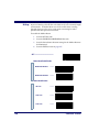
Understanding the Basics
If you have little or no prior experience with programming using bar
code labels, you should review this introductory section to familiarize
yourself with the basics of scanner programming before performing
any changes to your scanner’s configuration. Contents of this section
are:
•
Integrating the Scanner With Your Host System
- Changing Interfaces
•
Customizing Your Scanner’s Operation
•
Programming Overview
- What Is Programming Mode?
•
Programming Session
- Programming Sequence
•
LED and Beeper Indicators
•
If You Make a Mistake...
- Return to Factory Settings
•
Programming Guide
Where To Go From Here
1
Integrating the Scanner With Your Host System
Your scanner MUST be equipped with the correct hardware (interface
board, cable, etc.) to properly communicate with your host system.
Contact your PSC dealer for information if you have questions about
your scanner’s hardware compatibility.
You may also want to contact the dealer or your system administrator
if you have no record of how your scanner was pre-programmed at the
factory. Scanners are typically programmed with the default settings
for specific interface types, however, your scanner may have been custom configured with settings that are unique to your company or
application.
Once you know the scanner’s current settings, you can determine what
changes will be required to allow communication with your host system and/or optional features you choose to modify to customize your
installation. After recording the modifications needed, finish reading
this section, then turn to the appropriate page and follow the instructions to program the scanner.
When all scanner features are programmed to your satisfaction, the
scanner is ready to be placed into operation.
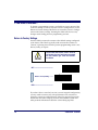
Changing Interfaces
When moving the scanner to a host terminal of a different interface
type than previously connected, it may be necessary to alter the scanner’s hardware and/or software to allow connection and communication between the two devices.
Hardware
Interface
Board
2
An interface board swap is usually unnecessary, since multiple host
interface protocols are supported in combination on most interface
boards. For example, RS-232, Standard Keyboard Wedge, and Wand
Emulation are all available on a single interface board. Activation of
alternate available interfaces on these boards requires only that you
connect the scanner to the new host using the appropriate interface
cable. The scanner will automatically change to the interface functions
specific to that cable.
PowerScan® Scanner
To determine if your desired new interface is available on your scanner,
check the following section titled Software on page 4. The section lists
host interface types supported by each interface board available at the
time of this writing. If you are still unsure of your scanner’s available
interface connectivity, consult your PSC dealer.
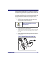
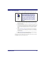
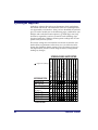
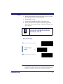
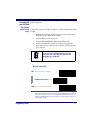
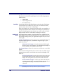
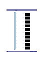
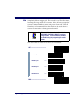
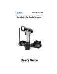
The scanner will need to be sent to a Level I Service repair depot if the
interface board must be swapped; however, if necessary, you can
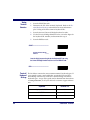
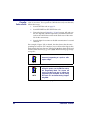
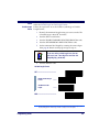
change your scanner’s interface cable by following these instructions.
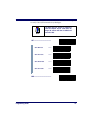
(Refer to Figure 1.):
1.
Loosen the screw at the bottom of the handle. This screw is
captive and does not come all the way out.
DO NOT try to pull the end cap off, as this may
damage the scanner.
CAUTION
2.
Swing the forked cable retainer clear of the square hole in the
end cap and rotate away from the cable.
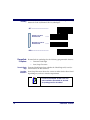
3.
Holding the scanner handle and end cap together in one hand,
pull the connector out of the handle end cap to free the interface cable.
4.
Connect the new interface cable at the scanner and rotate the
forked cable retainer to secure it. Tighten the screw to between
6 and 10 in-lbs.
Figure 1. Removing/Replacing the Interface Cable
1
3
Programming Guide
2
3
Software Verify that your scanner supports the desired interface1. The list below
indicates the interface groupings the scanner supports. Contact your
nearest PSC service depot if you don’t know your scanner’s group, or
need assistance to change the scanner to another interface group.
The Standard Keyboard Wedge/Wand Emulation/RS-232 Group
supports:
•
I/F Type A - PC/XT w/Alternate Key Encoding
•
I/F Type B - AT, PS/2 25-286, 30-286, 50, 50Z, 60, 70, 80, 90 & 95
w/Alternate Key Encoding
•
I/F Type C - PS/2 25 and 30 w/Alternate Key Encoding
•
I/F Type D - PC/XT w/Standard Key Encoding
•
I/F Type E - AT, PS/2 25-286, 30-286, 50, 50Z, 60, 70, 80, 90 & 95
w/Standard Key Encoding
•
I/F Type F - PS/2 25 and 30 w/Standard Key Encoding
•
I/F Type H - IBM® 3xxx w/102 keyboard
•
I/F Type I - PS/555530T w/104 keyboard
•
I/F Type J - NEC®9801 keyboard
•
Wand Emulation
•
RS-232
•
WN2-RS-232 (SNI)
The IBM/RS-232 Group supports:
•
IBM Port 5B
•
IBM Port E
•
IBM Port 9B
•
RS-232
•
IBM Port 17
•
WN-RS-232
The Universal [Keyboard] Wedge Group:
•
Consult the Universal Wedge Connectivity Guide3 for more information.
•
For additional configuration/programming, refer to the Universal Wedge Programming Guide3.
1. Contact your dealer or sales representative if your desired interface is not listed. Interface group
definitions are subject to change without notice.
2. Wincor Nixdorf® (formally SNI)
3. Contact your dealer or visit the website listed on the back cover of this manual for publications.
4
PowerScan® Scanner
After familiarizing yourself with the basic scanner programming procedures in this section, turn to the appropriate interface programming
section (RS-232, Wand Emulation, etc.) of this manual to set other interface features, completing the scanner’s conversion to a new interface
type.
Upon changing a scanner’s interface setting, scan a bar code to verify
that the scanner communicates correctly with the new host system.
Some sample bar codes are provided in Appendix B: Sample Bar Codes
on page 145. If any changes to the scanner’s factory settings are
needed, consult Customizing Your Scanner’s Operation below.
Customizing Your Scanner’s Operation
Most scanner programming falls within three general categories:
•
Interface Selection and Settings - are the mandatory settings
necessary to allow communication with your host terminal.
Examples of these settings are: RS-232 baud rate and parity.
NOTE
Ensure that your planned modifications are compatible with the current interface. For example,
baud rate selections are only valid in the RS-232
interface. The scanner will sound an error tone
when scanning programming labels for features
invalid to the current interface group.
•
Symbology Selection and Settings - gives the scanner the
capability to autodiscriminate as few as one, and as many as all
available symbologies. For optimal scanner performance
enable only those symbologies required. Additionally the scanner may be programmed with the standard options available
for the various symbologies, such as check digit, minimum
label length, fixed and variable length bar codes, QuadraLogic
Decoding, etc.
•
General Feature Settings - are features common to all interface
types. Examples include beeper adjustments such as volume
and length, read verification settings, etc.
If you experience difficulties, have questions or require additional
information, contact your local distributor, or call your dealer or sales
representative.
Programming Guide
5
Programming Overview
The scanner’s programmable feature settings can be modified to
accommodate your system’s unique requirements. These settings can
be communicated to the scanner in one of two ways:
1.
Commands can be sent directly from the host. A limited set of
host commands are available. Refer to Appendix A: Additional
Information on page 143 for more details.
2.
The easiest, most comprehensive way to program the scanner
is to use the Configurator Express™ On-Screen Programmining
Kit. Ask your dealer for more information about this product.
3.
Programming bar code labels can also be used to modify the
scanner’s programmable settings. This manual provides the
bar code labels and instructions necessary to configure the
scanner’s features/options.
NOTE
When you program the scanner using any of
the methods above, the scanner will store the
changes until reprogrammed or returned to
factory defaults.
What Is Programming Mode?
Programming Mode is a state in which the scanner must be placed in
order to accept programming commands. When programming using
the bar code labels in this manual, the scanner is typically placed in
Programming Mode by scanning the “SET” label at the top of most
programming feature pages.
While in the Programming Mode, the scanner only recognizes the special programming bar codes contained in this programming guide. See
the section, LED and Beeper Indicators on page 11 for information about
scanner indications while in the Programming Mode.
6
PowerScan® Scanner
Programming Session
A typical programming session is conducted as follows:
1.
Scan the SET bar code at the beginning of each set of programming bar codes to place the scanner in Programming Mode.
The scanner will emit three beeps, indicating it has read the bar
code and the green LED will flash on and off slowly while the
scanner remains in Programming Mode. Normal scanning
functions are disabled.
2.
Scan the programming label(s) that is (are) specially encoded
to make the desired changes. With few exceptions1, the scanner
will emit a triple beep each time you scan a valid programming
bar code.
NOTE
Not all features are available for all interfaces
and the scanner will sound an error tone when
scanning programming bar codes for features
invalid to the current interface. Only features
supported by the currently active interface will
be implemented.
NOTE
If a label is scanned that changes the scanner’s interface, all previous configuration
items scanned in the programming session
are lost.
Additionally, when programming a feature requiring you to scan single digits to set a multi-digit number, such as Minimum Label Length,
scanning the END bar code (or any item tag/item value bar code)
before completing all input will result in an error tone and cause the
scanner to exit Programming Mode. Under these circumstances, the
current feature you were trying to set is thrown out; any previous bar
codes scanned during the session will take effect.
1. Some features, such as Minimum Label Length, require you to select the label’s length by scanning a series of single-digit bar codes. A single ‘good read’ beep is sounded when scanning these
single digits in Programming Mode. Only the final required digit in the sequence will produce a triple beep when scanned, indicating a successfully programmed feature.
Programming Guide
7
NOTE
3.
It is recommended that programming sessions be limited to one feature at a time.
Should you make a mistake in the programming sequence, it can be difficult to discover
where an error has been made if several features are programmed at once. Additionally, it
can be confusing to determine which features
may or may not have been successfully set
following such a session.
Scan the END label at the bottom of the page to save any new
settings and exit Programming Mode. The scanner will sound
a beep and reset upon exiting Programming Mode, and the
green LED will return to its usual state (on steady or off).
The scanner will not exit Programming Mode unless the END
bar code is scanned or power is disconnected. Disconnecting
power during Programming Mode, before scanning the END
label, will cause all new settings to be ignored. On power-up,
the scanner will return to previous settings.
4.
8
Maintain a good record of all changes made to ensure that you
know if the original factory settings have been changed.
PowerScan® Scanner
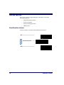
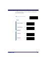
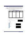
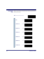
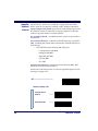
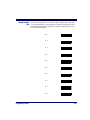
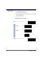
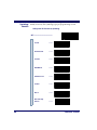
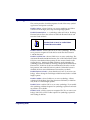
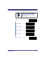
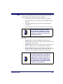
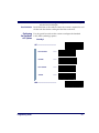
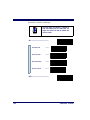
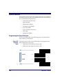
Programming To modify a scanner feature (item), the programming bar codes conSequence tained in this manual must be scanned in a given sequence depending
upon the feature being programmed (as shown in Table 1). There are
three possible programming sequences:
A. Programming sample A (the most commonly used format)
demonstrates how three bar codes are scanned in sequence to
do the following:
1.
Place the scanner in Programming Mode (SET bar code).
2.
Scan the Item Tag1 that will enable the new feature.
3.
End the programming session and reset the scanner (END
bar code).
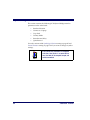
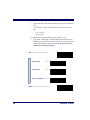
B. Sample B provides an example of a programming feature
requiring the entry of a range value. Like sample A, the scanner is placed in Programming Mode and an Item Tag1 is
scanned. Then, a value must be entered before ending the programming session. In the example, three digits must be
scanned from the number pad in Appendix C: Keypad. This type
of format, requiring a total of as many as six programming bar
codes, is necessary to allow flexible programming with larger
item value numeric ranges.
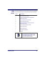
C. The programming sequence shown in example C requires
scanning of a single, extended length bar code. This special
programming bar code contains all the data necessary to enter
Programming Mode, set the Item Tag1 and Item Value, and exit
Programming Mode (all in one step).
1. An “Item Tag” is a term used to describe an assigned number, which is encoded in a programming
bar code, that toggles (selects, enables, disables, etc.) a specific programming feature.
Programming Guide
9
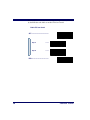
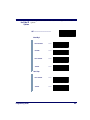
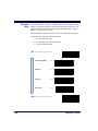
Table 1. Programming Sequence
SET
A
ITEM TAG
ITEM VALUE
END/RESET
1
2
3
SET
ENABLE
NEW FEATURE
END
1
2
345
6
0
B
SET
C
10
ENABLE NEW
FEATURE
USING THE
FOLLOWING
SETTINGS...
0
8
END
1
ONE BAR CODE CONTAINS SET + ITEM TAG + ITEM VALUE + END
PowerScan® Scanner
LED and Beeper Indicators
The scanner provides a set of indicators that verify/announce the various scanner functions.
LED Indicators The Amber “Laser ON” LED (located on top rear of scanner)
-
lights whenever laser power is on.
The Green “Good Read” LED (also located on top rear of scanner)
-
Flashes1 once to indicate when a “good read” has occurred.
-
Flashes1 slowly on and off to indicate the scanner is in Programming Mode.
The Beeper While in Scanning mode...
-
Sounds1 four times at power-up.
-
Sounds1 once following a “good read.”
-
Sounds1 six rapid “chirps” to indicate an error (error tone).
While in Programming mode...
-
Sounds1 one time when entering/exiting the Programming
Mode.
-
Sounds1 three times to indicate a successfully programmed
feature.
1. The green LED and Beeper are configurable features and may have been modified or disabled at
an earlier programming session. See the section in this manual titled General Features for
more details.
Programming Guide
11
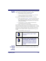
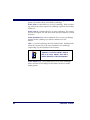
If You Make a Mistake...
If, during a programming session, you find that you are unsure of the
scanner’s settings or wish to reset the scanner’s configuration, use the
Return to Factory Settings label below to return the scanner’s configuration to the factory settings. Scanning this label will also reset any
changes made during previous programming sessions.
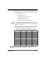
Return to Factory Settings
Scan this label to return the scanner to the default settings configured
at the factory. This label is typically used to return the scanner to a
“known” operating state when the present programming status is not
known, faulty, or suspect.
CAUTION
Use this label with caution, since it will reset
ALL features that may have been programmed
for that interface type since the scanner’s
installation.
SET -------------------------------------------
Return to Factory Setting ---------
END ------------------------------------------
If you don’t have a record of your site/system’s original configuration,
you may need to contact your sale representative for assistance to
return the scanner to normal function. Please be prepared to provide
information about the company, location, host terminal system and
other pertinent information about the scanner being repaired.
12
PowerScan® Scanner
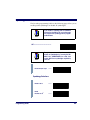
Where To Go From Here
Programming is easy and straightforward if you follow these steps:
NOTE
If you are changing some interface types (for
example; if you are moving the scanner from a
Universal Keyboard Wedge to an RS-232 host)
you must first change the hardware. Replace
the scanner’s interface board (if required) and
connect the scanner using the new interface
cable BEFORE performing any programming
changes.
1.
If you are changing the scanner’s interface type, follow the
instructions in the section titled, Changing Interfaces on page 2
before proceeding.
2.
Scan any feature bar codes that are unique to the interface you
are currently programming. These interface specific programming bar codes immediately follow each interface selection
label.
3.
Turn to Symbologies Supported on page 62 if you are going to
change any bar code symbologies or modify any symbologyrelated features.
4.
Turn to General Features on page 132 if you wish to change or
modify any of the scanner’s other features.
Once the necessary changes have been made, and you have scanned
the END bar code, you are ready to scan.
Programming Guide
13
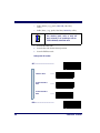
Interface Selection
This section contains programming bar code labels to select the
following interfaces:
•
Wand Emulation Interface
•
Pre-Noise Settings
•
Keyboard Wedge Interface
•
IBM Interface
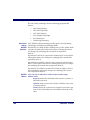
Wand Emulation Interface
Scan these labels to enable the Wand Emulation Interface.
SET -------------------------------------------
Enable Wand Emulation ---------
END ------------------------------------------
14
PowerScan® Scanner
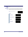
Wand Emulation Settings
Use these programming bar codes to configure the settings for the
Wand Emulation Interface.
SET -------------------------------------------
Polarity
Space Low, Bar High
---------
Space High, Bar Low
---------
Signal Speed
Programming Guide
Low (660 µs)
---------
High (330 µs)
---------
15
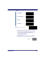
Data Format
Transmit in Normal
Format
---------
Transmit in C39
Format
---------
Transmit in C39 Full ASCII
Format
---------
Transmit in C128
Format
---------
Idle State
16
Low
---------
High
---------
PowerScan® Scanner
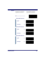
Transmit C128 Function
Characters
Enablea
---------
Disable
---------
END ------------------------------------------
a. This feature should only be enabled when the Wand Data Format is configured for Transmit in Normal Format or Transmit in Code 128 Format.
Programming Guide
17
Wand
Emulation Pre/
Post-Noise
Settings
The number of noise transitions generated prior to or following label
transitions are independently configurable options. To set either pre- or
post-noise transitions, enter Programming Mode by scanning the SET
bar code, then follow these steps:
1.
Scan Don’t Transmit Pre-Noise or Don’t Transmit Post-Noise,
followed by the END bar code to disable noise transitions, or...
2.
Scan the Set Pre- or Post -Noise Transitions bar code followed
by the digits from Appendix C: Keypad that represent the
desired number of noise transitions. Select from one to twenty1
noise transitions for either pre- or post-noise. Complete the
programming sequence by scanning the END bar code.
NOTE
Settings for this feature have been enhanced
since the product was originally released, adding the option to select a specific quantity of
noise transitions. If your scanner has a date
code of February, 2001 or before, pre-noise/
post-noise transitions are enabled by following
Step 2 above, EXCEPT the single digit selected
from Appendix C: Keypad MUST be one (1).
This will either set the pre-noise transitions to
one or the post-noise transitions to three
depending on which feature is being programmed. The feature is disabled in the same
manner as Step 1 above.
Pre-Noise
Settings
SET -------------------------------------------
Pre-Noise
Don’t Transmit
Pre-Noise
---------
1. Scanners with a date code of February of 2001 or before MUST select the digits zero-one (01).
See the note on this page for details.
18
PowerScan® Scanner
Set Pre-Noise Transitions ---------
Scan two digits representing the desired number of Pre-Noise Transitions
using the number pad from Appendix C: Keypad, padded with leading zeros
(example: 03 = three transitions, 08 = eight, 15 = fifteen, etc.)
END ------------------------------------------
Post-Noise Settings
SET -------------------------------------------
Post-Noise
Don’t Transmit PostNoise
---------
Set Post-Noise Transitions ---------
Scan two digits representing the desired number of Post-Noise Transitions
using the number pad from Appendix C: Keypad, padded with leading zeros
(example: 03 = three transitions, 08 = eight, 15 = fifteen, etc.)
END ------------------------------------------
Programming Guide
19
RS-232 Interface/WN-RS-232 (SNI) Interface
Scan these labels to enable either the standard RS-232 interface
(PSC RS-232) or the WN-RS-232 (SNI) Interface.
SET -------------------------------------------
Enable Standard
RS-232
---------
Enable WN-RS-232
---------
END ------------------------------------------
RS-232 Communication Parameters
This section contains the following RS-232 communication parameters
in the order listed:
•
Baud Rate
•
Data Format Settings
- Data Bit
- Parity Bit
- Stop Bit(s)
•
Handshaking
- Hardware Handshaking (CTS/RTS)
- Software Handshaking (Xon/Xoff)
•
ACK/NAK Options
•
Intercharacter Delay
Go to the sections titled Symbology Selection starting on page 65 and
General Features on page 132 if you want to change any other settings
for this interface.
20
PowerScan® Scanner
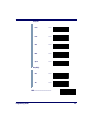
Baud Rate Use the bar codes on this page to select the communications Baud Rate.
Only one Baud Rate selection may be active at any one time. The last
Baud Rate label you scan during a programming session will be the setting that is stored when you scan the END label.
SET -------------------------------------------
Baud Rate = 1200
---------
Baud Rate = 2400
---------
Baud Rate = 4800
---------
Baud Rate = 9600
---------
Baud Rate = 19200
---------
Baud Rate = 38400
---------
END ------------------------------------------
Programming Guide
21
Data Format The bar codes on this page can be used to select the data format configSettings uration needed to communicate with your system. Refer to Table 1,
RS-232 Data Format below for acceptable combinations of these setting.
Data Format
Table
There are many possible data format configurations for an RS-232
interface. Check your host system manual to find out your system's
communications requirements.
Table 1. RS-232 Data Format
Data Bit
Parity Bit
Stop Bit(s)
Start Bit
Seven
0
2
1
Seven
1
1
1
Seven
1
2
1
Eight
0
0
1
Eight
0
2
1
Eight
1
1
1
Use these bar codes to set the Data Format options desired.
SET -------------------------------------------
Data Bit
22
Seven
---------
Eight
---------
PowerScan® Scanner
Parity Bit
None
---------
Even
---------
Odd
---------
Mark
---------
Space
---------
Stop Bit(s)
One
---------
Two
---------
END ------------------------------------------
Programming Guide
23
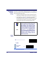
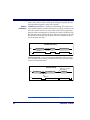
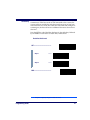
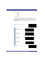
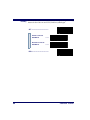
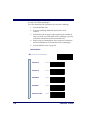
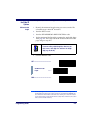
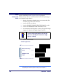
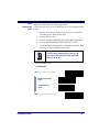
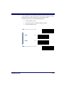
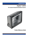
Handshaking Review your system documentation to identify handshaking requirements, and use these labels to change the settings if required. The following brief descriptions explain each selection.
Hardware
Handshaking
CTS/RTS Flow Control - is hardware handshaking. The scanner activates the RTS (Request to Send) line when it is ready to send data to the
host. The scanner waits for an active Clear to Send (CTS) signal from
the host before transmitting data. If hardware control is disabled, CTS/
RTS communication will not take place. If the host deactivates the CTS
line during data transmission, the host will receive additional characters for no more than 2ms1.
CTS/RTS Flow Control
Data
Label Transmission
Disabled
Xmission
Label Transmission
Active
CTS
Inactive
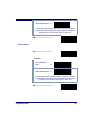
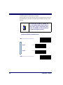
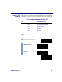
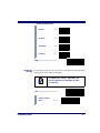
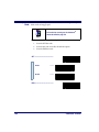
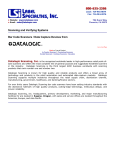
CTS Scan Control - is also a hardware handshaking. When scan control is enabled, label scanning is disabled until CTS is asserted and deasserted as illustrated below.
CTS Scan Control
Data
Label 1
Label 1
Will not scan again
until toggled
Label 2
Disabled until
Assert
CTS
De-assert
1. Timing varies slightly depending upon the baud rate selected.
24
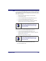
PowerScan® Scanner
Handshaking controls are mutually exclusive. The settings below
allow only one of these features to be enabled at a time, as enabling
multiple controls will produce unpredictable results.
NOTE
Each of the handshaking features requires
that a series of bar codes (Step #1, Step #2) in
the sequence given. That is, you must enter
Programming Mode by scanning the SET bar
code, scan the bar codes required to set one
handshaking feature, then scan the END bar
code.
Scan the SET bar code label then the Step #1, Step #2 below, followed
by the END bar code labels to enable CTS/RTS Flow Control.
Enable CTS/RTS Flow Control
SET -------------------------------------------
Step #1
---------
Step #2
---------
END ------------------------------------------
Programming Guide
25
Scan the SET bar code label then the Step #1, Step #2 below, followed
by the END bar code labels to enable CTS Scan Control.
Enable CTS Scan Control
SET -------------------------------------------
Step #1
---------
Step #2
---------
END ------------------------------------------
26
PowerScan® Scanner
Software
Handshaking
Xon/Xoff - is software handshaking that allows the host to control data
transmission. If the host sends an Xoff command to the scanner, the
scanner will not send the bar code data until it receives an Xon command from the host. If the host sends the Xoff command during data
transmission, the host will receive additional characters for no more
than 2ms1.
Scan the SET bar code label then the Step #1, Step #2 below, followed
by the END bar code labels to enable Xon/Xoff Control.
Enable Xon/Xoff Control
SET -------------------------------------------
Step #1
---------
Step #2
---------
END ------------------------------------------
1. Timing varies slightly depending upon the baud rate selected.
Programming Guide
27
Disable both CTS/RTS and Xon/Xoff Controls - disables both the
CTS/RTS and Xon/Xoff software controls.
Scan the SET bar code label then the Step #1, Step #2 below, followed
by the END bar code labels to disable both CTS/RTS and Xon/Xoff
Control.
NOTE
To disable either CTS/RTS or Xon/Xoff, you
must first DISABLE BOTH CRTS/RTS and Xon/
Xoff Control using the programming labels
below. Then ENABLE the desired handshaking feature from page 25 or page 27.
Disable both CTS/RTS and Xon/Xoff Control
SET -------------------------------------------
Step #1
---------
Step #2
---------
END ------------------------------------------
28
PowerScan® Scanner
RS-232 ACK/ Several ACK/NAK parameters can be set for your scanner.
NAK Options Options for RS-232 ACK/NAK are:
•
Disable ACK/NAK
•
Enable ACK/NAK for bar code transmission
•
Enable ACK/NAK for host command acknowledge
•
Enable ACK/NAK for bar code transmission and host command acknowledge
RS-232 ACK/NAK Options
SET -------------------------------------------
Disable ACK/NAK
---------
Enable for Bar Code
Transmission
---------
Enable for Host Command
Acknowledge
---------
Enable for Bar Code
Transmission and
Host Command
Acknowledge
---------
END ------------------------------------------
Programming Guide
29
RS-232 Intercharacter Delay refers to the pause, if any, between each character
Intercharacter before it is sent to the host. This time delay is used to control the flow of
Delay data from the scanner.
SET -------------------------------------------
30
None
---------
10 Milliseconds
---------
20 Milliseconds
---------
30 Milliseconds
---------
40 Milliseconds
---------
50 Milliseconds
---------
100 Milliseconds
---------
PowerScan® Scanner
200 Milliseconds
---------
500 Milliseconds
---------
1 Second
---------
END ------------------------------------------
Programming Guide
31
Keyboard Wedge Interface
This section contains the following PC Keyboard Wedge interface
parameters in the order listed:
•
Interface Selection
•
Connect to a Laptop
•
Caps Lock
•
Country Mode
•
Intercharacter Delay
•
Quiet Interval
Go to the sections titled Symbology Selection starting on page 65 and
General Features starting on page 132 if you want to change any other
settings.
NOTE
32
If the transmission parameters are configured
such that a label results in no actual data to
send, the label will be accepted, beeped, and
no data transmitted.
PowerScan® Scanner
PC Keyboard This scanner supports a variety of PC Keyboard interfaces. The table
Wedge below defines the different interface selections. Scan the corresponding
Interface bar code starting on page 34 to select the desired keyboard interface.
Selection
I/F Type
PCs Supported
A
PC/XT w/Alternate Key Encoding
B
AT, PS/2 25-286, 30-286, 50, 50Z, 60, 70, 80, 90 & 95
w/Alternate Key Encoding
C
PS/2 25 and 30 w/Alternate Key Encoding
D
PC/XT w/Standard Key Encoding
E
AT, PS/2 25-286, 30-286, 50, 50Z, 60, 70, 80, 90 & 95
w/Standard Key Encoding
F
PS/2 25 and 30 w/Standard Key Encoding
G
IBM 3xxx w/122 keyboard
H
IBM 3xxx w/102 keyboard
I
PS/55 5530T w/104 keyboard
J
NEC 9801
We recommend that you disconnect power
before plugging/unplugging cables to avoid
any possibility of equipment damage.
NOTE
Programming Guide
33
Scan the bar codes corresponding to the applicable Keyboard type
listed on page 33.
PC Keyboard Interface Type
SET -------------------------------------------
34
A
---------
B
---------
C
---------
D
---------
E
---------
F
---------
G
---------
PowerScan® Scanner
H
---------
I
---------
J
---------
END ------------------------------------------
Programming Guide
35
Connect to a
Laptop/No
Keyboard
Attached
If no keyboard is attached, the scanner must provide the acknowledge
signal to the PC. In this case, enable the "Laptop/No External Keyboard" mode. If a keyboard is attached, enable "Keyboard Attached."
Laptop (integrated keyboard) -provides the acknowledge signal to the
PC when the scanner is connected to a laptop computer or when the
scanner is operated with no external keyboard.
PC (external keyboard) - is enabled when the scanner is connected to a
standard PC."
Send Control Characters - transmits all ASCII characters except NUL
(00h) . Disabling this feature limits transmission of ASCII characters to
the following:
•
Only ASCII characters between 20h..127h, plus.
-
Carriage Return (CR=0Dh)
-
BackSpace (BS=08h)
-
Right Tab (HT=09h)
-
Left Tab (0Bh)
-
Esc (1Bh)
Send Function Character - transmits characters between 00H - IFH
which are not in the normal ASCII set.
Scan the bar code belows below to select the applicable option for connecting to a laptop or PC.
SET -------------------------------------------
Connect to Laptop or PC
36
Laptop/No external
Keyboard
---------
Keyboard Attached
---------
PowerScan® Scanner
Send Control/Function
Characters
Enable Control
Characters
---------
Enable Function
Characters
---------
Disable
---------
END ------------------------------------------
Programming Guide
37
Caps Lock Three caps lock settings are available. These are:
•
Caps Lock Off - sends character data (to the host in normal format.
•
Caps Lock On - sends character data (to the host) in reverse
case:
(a.z) = (A.Z)
(A.Z) = (a.z)
Use this feature if your keyboard's caps lock key is on.
•
Caps Lock = Shift-Lock - sends character data (to the host) in
shifted case. Use this feature if you choose to use the keyboard
with the shift lock key left on. For use with interface type G
(IBM 3xxx 122-keyboard) ONLY.
SET -------------------------------------------
Caps Lock OFF
---------
Caps Lock ON
---------
Cap Locks = Shift Lock
---------
END ------------------------------------------
38
PowerScan® Scanner
Country Mode The following country/languages can be selected when configured for
I/F Type E only:
• USA
• France
• Portugal
• Belgium
• Germany
• Spain
• Britain
• Italy
• Sweden
• Denmark
• Norway
• Switzerland
• Japanese 106-Key
Scan the bar code below to selected the desired country.
SET -------------------------------------------
Programming Guide
USA
---------
Belgium
---------
Britain
---------
Denmark
---------
France
---------
39
Germany
---------
Italy
---------
Norway
---------
Portugal
---------
Spain
---------
Sweden
---------
Switzerland
---------
Japanese 106-Key
---------
END ------------------------------------------
40
PowerScan® Scanner
Keyboard
Wedge
Intercharacter
Delay
Intercharacter Delay refers to the pause, if any, between each character
before it is sent to the host. This time delay is used to control the flow of
data from the scanner. Use these labels to select the desired Intercharacter Delay.
SET -------------------------------------------
Programming Guide
None
---------
5 Milliseconds
---------
10 Milliseconds
---------
20 Milliseconds
---------
30 Milliseconds
---------
40 Milliseconds
---------
60 Milliseconds
---------
41
80 Milliseconds
---------
90 Milliseconds
---------
END ------------------------------------------
42
PowerScan® Scanner
Quiet Interval Quiet Interval is the amount of time to look for keyboard activity
before the scanner breaks the keyboard connection in order to transmit
data to the host.
SET -------------------------------------------
10 Milliseconds
---------
20 Milliseconds
---------
50 Milliseconds
---------
100 Milliseconds
---------
200 Milliseconds
---------
500 Milliseconds
---------
1 Second
---------
END ------------------------------------------
Programming Guide
43
Universal To activate the Universal Wedge interface, follow these instructions:
Wedge
1. Scan the START bar code.
Terminal
2. Determine the I.D. of the terminal/keyboard. Refer to the TerSelection
minal/Keyboard Settings section below for more information
plus a listing of the most common keyboard I.D.s.
3.
Scan the Activate Universal Wedge Interface bar code.
4.
Use the Universal Wedge Number Pad to scan in the digits for
the keyboard I.D. number you determined in step 2.
5.
Scan the END bar code.
START----------------------------------------
Activate Universal Wedge
Interface
---------
Scan the digit(s) representing the desired keyboard I/F type using
the Universal Wedge Number Pad, then scan the END bar code.
END ------------------------------------------
Terminal/ The list below contains the most common terminal/keyboard types. If
Keyboard your specific system is not listed below, consult the Universal KeySettings board Wedge Connectivity Guide for a detailed listing of terminal/
keyboard types. A copy of the guide can be obtained from the internet
at www.pscnet.com, or call your dealer for customer support information.
44
Keyboard
Terminal I.D.
High Speed PC/AT, PS2
591
PC AT, PS2
11
MAC
25
PowerScan® Scanner
Universal The default communication mode (factory settings) is Keyboard Wedge
Wedge Number of PC AT (keyboard I.D. 11). Use the codes on this page to select the
Pad I. D. corresponding to your computer or terminal (reference the Universal Keyboard Wedge Connectivity Guide for this product or call
PSC Customer Support).
0 →
1 →
2 →
3 →
4 →
5 →
6 →
7 →
8 →
9 →
Programming Guide
45
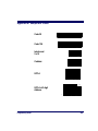
IBM Interface
The IBM Group supports:
•
Port 5B
•
Port 9B
•
Port 17
•
Port E
Scan the SET bar code to enter the programming mode, then scan the
programming bar code below to activate the desired interface, followed by the END bar code to exit the programming mode and reset
the scanner.
SET -------------------------------------------
Enable Port 5B
---------
Enable Port 9B
---------
Enable Port 17
---------
Enable Port E
---------
END ------------------------------------------
46
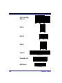
PowerScan® Scanner
Transmit When this feature is enabled, the symbology identifier for the specified
Labels in Code label will be set to Code 39 and the label will be transmitted. No data
39 Format checking or conversion is done. Table 2 below shows the symbologies
converted.
Table 2. Symbologies Converted to Code 39
Port
Symbology Converted
Port 5B
Code 128, Code 93, Codabar
Port 9B
Code 93, Codabar
Port 17
No Effect
Port E
No Effect
Scan the bar codes below to enable/disable the Conversion to Code 39
option.
SET -------------------------------------------
Enable Conversion to
Code 39
---------
Disable Conversion to
Code 39
---------
END ------------------------------------------
Programming Guide
47
Label Transmit Configuration (RS-232 and Keyboard Wedge Interfaces only)
If you need to send information in addition to bar code label data, the
scanner can be configured to transmit Global Prefixes (also known as
preambles), Global Suffixes (also known as postambles), and symbology specific identifier characters (termed Label I.D.).
Prefix, Suffix, and Label I.D.
The table below shows examples of how Prefix, Suffix, and Label I.D.
characters can be applied.
Column three contains the label data, while columns one, two, four
and five contain the additional characters added by way of the Prefix,
Label I.D. as Prefix, Label I.D. as Suffix, and Global Suffix respectively.
The last column shows the resulting data that will be transmitted when
the additional characters are applied.
Using this feature requires a thorough understanding of your specific system requirements. If you
have questions or need assistance with these features, call your system specialist or PSC technical
support.
NOTE
Table 3. Prefix, Suffix, Label I.D. Examples
Global
Prefix
(00 = No
Char.)
Label Data
Label I.D. as
Suffix
Global Suffix
(00 - No
Char)
1st
Char
(Examples)
1st
Char
1st
Char
1st
Char
2nd
Char
00
00
None
0998875
None
00
00
0998875
50
51
None
0011223344
None
000
000
PQ0011223344
2nd
Char
2nd
Char
2nd
Char
Resulting Label
Format
00
00
46
46
00210126
None
00
00
FF00210126
50
51
41
a
00
00210126
None
00
00
PQA210126
00
00
None
$99.95
25
00a
50
51
None
998875
25
00a
00
00
$99.95%
00
00
PQ998875E
00
00
None
101234567891
None
53
57
10123456789SW
50
51
None
Code39Test
None
53
57
PQCode39TestSW
00
00
45
00a
Code128
None
53
00
ECode128S
50
00
45
46
0998875
None
53
57
PFF09988875SW
00
00
None
0998875
46
46
53
57
0998875FFSW
50
51
None
0011223344
46
00*
53
57
PQ0011223344FSW
a.
48
Label I.D. as
Prefix
No second character
PowerScan® Scanner
Setting Global One or two prefix characters may be added to the standard label forPrefix(es) mat when desired. For the addition of more than two prefix characters,
contact your distributor or technical support representative for Full
Label Edit (FLE) options.
Identify your specific system requirements before adding or modifying
these settings, then follow these steps:
1.
Look at the ASCII chart shown on the inside back cover of this
manual, and identify the ASCII character(s) and the corresponding Hex Code(s) for the ASCII characters you will use as
prefixes.
For example, if you are going to send two prefix characters as ‘STX’
(start transmit) and ‘SP’ (Space), the ASCII chart shows that ‘STX’
equals 02 hex and ‘SP’ equals 20 hex.
2.
Scan the SET bar code on page 50.
3.
Scan the SET PREFIX bar code.
4.
Turn to Appendix C: Keypad on page 147, and scan the four digits corresponding to the hex values determined in step one
above. (For the example, scan 0, 2, 2, 0). Return to this page and
go to step five.
Successful programming of a prefix requires 4
digits.
NOTE
NOTE
5.
If you make a mistake or lose your place while
setting this option, scan the END bar code to
exit Programming Mode. The scanner will
sound a two-beep error tone to indicate that
programming was incomplete, and the setting
will remain as it was before entering Programming Mode.
Scan the END bar code.
You have added a two character prefix to all bar code data, regardless
of label symbology, that will be added to the label data before it is sent
to the host.
Programming Guide
49
Setting Global Prefix(es)
SET -------------------------------------------
Set Prefix
---------
END ------------------------------------------
Setting Global One or two suffix characters may be added to the standard label format
Suffix(es) when desired. For the addition of more than two suffix characters, contact your distributor or technical support representative for Full Label
Edit (FLE) options.
Identify your specific system requirements before adding or modifying
these settings, then follow these steps:
1.
Look at the ASCII chart shown on the inside back cover of this
manual, and identify the ASCII character(s) and the corresponding Hex Code(s) for the ASCII characters you will use as
suffixes.
For example, if you are going to send two suffix characters as ‘LF’ (Line
Feed) and ‘CR’ (Carriage Return). The ASCII chart shows that ‘LF’
equals 0A hex and ‘CR’ equals 0D hex.
2.
Scan the SET bar code on page 51.
3.
Scan the Set Suffix bar code.
4.
Turn to Appendix C: Keypad on page 147, and scan the four digits corresponding to the Hex Values determined in step one
above. (For the example, scan 0, A, 0, D). Return to this page
and go to step five.
IMPORTANT NOTE
50
If you are using the Universal Wedge interface,
do not modify the suffix setting. Refer to the
Universal Wedge Programming Guide to modify the suffix settings.
PowerScan® Scanner
Successful programming of a suffix requires
4 digits.
NOTE
NOTE
5.
If you make a mistake or lose your place while
setting this option, scan the END bar code to
exit Programming Mode. The scanner will
sound a two-beep error tone to indicate that
programming was incomplete, and the setting
will remain as it was before entering Programming Mode.
Scan the END bar code.
You have added a two character suffix to all bar code data, regardless
of label symbology, that will be added to the label data before it is sent
to the host.
Setting Global Suffix(es)
SET -------------------------------------------
Set Suffix
---------
END ------------------------------------------
Programming Guide
51
Single The scanner will not transmit a prefix, or suffix character if its hex
Character value is set to zero. To set a prefix or suffix that has only one character,
Prefix or Suffix follow these steps:
1.
Scan the SET bar code on page 53.
2.
Scan SET PREFIX or SET SUFFIX bar code.
3.
Turn to the keypad (Appendix C: Keypad on page 147) and scan
the two-digit hex code that represents your desired character
(refer to the ASCII chart on the inside back cover of this manual for this conversion).
4.
Scan the digit ‘0’ two times to disable transmission of a second
character.
For example, if ‘Space’ (SP) is desired, the chart shows that the corresponding hex code for ‘SP’ is 20, thus you would scan the digit 2, then
the digit 0 for the first character, followed by 00 digits from the keypad
for the second character, (e.g., scan 2,0,0,0). Return to this page and go
to step five.
Successful programming of a prefix or suffix
requires 4 digits.
NOTE
NOTE
5.
52
If you make a mistake or lose your place while
setting this option, scan the END bar code to
exit Programming Mode. The scanner will
sound a two-beep error tone to indicate that
programming was incomplete, and the setting
will remain as it was before entering Programming Mode.
Scan the END bar code on page 53.
PowerScan® Scanner
Setting a Single Character Prefix/Suffix
SET -------------------------------------------
Set Prefix
---------
Set Suffix
---------
END ------------------------------------------
Programming Guide
53
Disabling To disable global prefix or suffix characters, follow these instructions:
Prefix or Suffix
1. Scan the SET bar code below.
2.
Scan SET PREFIX or SET SUFFIX.
3.
Scan the digit ‘0’ four times to disable the prefix or suffix characters. Go to step four.
4.
Scan the END bar code.
Disabling Global Prefix/Suffix Characters
SET -------------------------------------------
Set Prefix
---------
Set Suffix
---------
0
---------
END ------------------------------------------
54
PowerScan® Scanner
Setting Label Setting the Label I.D. feature can be a complex task requiring multiple
I.D. steps to enable all necessary options. You’ll want to familiarize yourself
with the contents of this section before proceeding. Here is a brief listing of the order of its contents:
•
Label Identifiers
•
Setting Label I.D. Locations
•
Setting Label I.D. Characters by Symbology
•
Label I.D. Symbology Selection
•
Setting Single Character Label I.D.
•
Disabling Label I.D. for a Specific Symbology
Label Symbology-specific label identifiers comprise one or two ASCII characIdentifiers ters that can precede or follow bar code label data as it is transmitted to
the host. The host may use these characters as a means of distinguishing between symbologies.
Industry standards have been established for symbology-specific label
identifiers, and are listed in the table below. Most scanners will have
factory default identifiers preset to these standards.
Table 4. Industry Standard Label Identifiers (all are prefixes)
Symbology
ID
Symbology
ID
UPC-A
UPC-E
A
EAN-8 (8 Add-ons)
FF
E
EAN-13 (2 Add-ons)
F
EAN-8
FF
EAN-13 (5 Add-ons)
F
EAN-13
F
EAN-13 (8 Add-ons)
F
UPC-A (2 Add-ons)
A
Code 39
*
UPC-A (5 Add-ons)
A
PharmaCode
A
UPC-A (8 Add-ons)
A
Codabar
%
UPC-E (2 Add-ons
E
Interleaved 2 of 5
i
UPC-E (5 Add-ons)
E
Standard 2 of 5
i
UPC-E (8 Add-ons)
E
Code 93
&
EAN-8 (2 Add-ons)
FF
Code 128
#
EAN-8 (5 Add-ons)
FF
UCC/EAN 128
None
MSI/Plessey
@
Setting Label Use the following bar codes to choose the position where Label I.D.
I.D. Location characters will be placed in relation to scanned label data:
Programming Guide
55
•
None (no Label I.D.), (e.g., prefix, label data, suffix)
•
Prefix (before), (e.g., prefix, label I.D., label data,
suffix)
•
Suffix (after) , (e.g., prefix, label data, label I.D., suffix).
Your selection (prefix, suffix, or none) will
apply universally to all symbologies and cannot be individually selected for each.
NOTE
1.
Scan the SET bar code.
2.
Scan the bar code for the desired position.
3.
Scan the END bar code.
Setting Label I.D. Location
SET -------------------------------------------
Label I.D. = None
---------
Position Label I.D. as
Prefix
---------
Position Label I.D. as
Suffix
---------
END ------------------------------------------
56
PowerScan® Scanner
Setting Label To set symbology-specific label identifiers (Label I.D.):
I.D. by
1. Look at the ASCII chart on the inside back cover, and identify
Symbology
the ASCII character(s) and the corresponding Hex Code(s) for
the ASCII characters you will use as identifiers.
For example: You need to change the Label I.D. for UPC-A to ‘A1’.
2.
Scan the SET bar code on page 58.
3.
Scan the bar code starting on page 58 representing the symbology whose Label I.D. you wish to modify. Scan only one symbology type per programming session.
In our example, we would scan the ‘UPC-A’ symbology bar code.
4.
Identify and scan the four digits from the Appendix C: Keypad
on page 147 that correspond to the Hex Values you determined
in step one above. Return to this page and go to step five.
The hex values from the ASCII chart that correspond to ‘A1’ from our
example are as follows: 41 hex = ‘A’, and 31 hex = ‘1’. Thus, we would
scan digit programming bar codes in this order: 4, 1, 3, 1.
5.
Scan the END bar code on page 60.
Successful programming requires 4 digits for
the Label I.D.
NOTE
You have changed the default Label I.D. for UPC-A from ‘A’ to ‘A1’.
Programming Guide
57
Label I.D. Scan the bar code representing the symbology whose label you want to
Symbology modify. Scan only one symbology type per programming session.
Selection
Setting Label I.D. Characters by Symbology
SET -------------------------------------------
58
Code 39
---------
PharmaCode 39
---------
Code 128
---------
UCC/EAN 128
---------
Interleaved 2 of 5
---------
Codabar
---------
UPC-A
---------
UPC-A w/2 digit
Add-ons
---------
PowerScan® Scanner
Programming Guide
UPC-A w/5 digit
Add-ons
---------
UPC-A w/C128
Add-ons
---------
UPC-E
---------
UPC-E w/2 digit
Add-ons
---------
UPC-E w/5 digit
Add-ons
---------
UPC-E w/C128
Add-ons
---------
EAN-13
---------
EAN-13 w/2 digit
Add-ons
---------
EAN-13 w/5 digit
Add-ons
---------
EAN-13 w/C128
Add-ons
---------
59
EAN-8
---------
EAN-8 w/2 digit
Add-ons
---------
EAN-8 w/5 digit
Add-ons
---------
EAN-8 w/C128
Add-ons
---------
Code 93
---------
Standard 2 of 5
---------
MSI/Plessey
---------
END ------------------------------------------
60
PowerScan® Scanner
Setting Single The scanner will not transmit a label I.D. character if its hex value is set
Character to zero. If you have determined that you need a Label I.D. that contains
Label I.D. only a single character, follow this modified procedure:
1.
Scan the SET bar code on page on page 58.
2.
Scan your selection from the list starting on page 58 for the
symbology identifier you plan to change.
For example, scan the EAN-8 bar code to select that symbology.
3.
Turn to the keypad (Appendix C: Keypad on page 147) and scan
the two-digit hex code that represents your desired character
(refer to the ASCII chart on the inside back cover of this manual for this conversion).
4.
Scan the digit ‘0’ two times to disable transmission of a
second character. Return to this page.
As an example, assume that you want to change the Label I.D. for
EAN-8 from the default setting “FF” to the single character “8”. In this
example, note that the chart shows that the ASCII character ‘8’ is equivalent to 38 hex, therefore the digits 3, then 8 should be scanned followed by two zeros (00) to indicate a single character I.D. (e.g., scan
3,8,0,0)
5.
Scan the END bar code on page 60.
Successful programming requires 4 digits for
the Label I.D.
NOTE
NOTE
If you make a mistake or lose your place while
setting this option, scan the END bar code to
exit Programming Mode. The scanner will
sound a two-beep error tone to indicate that
programming was incomplete, and the setting
will remain as it was before entering Programming Mode.
Disabling This procedure is the same as Setting Single Character Label I.D. above,
Label I.D. for a except you should scan four zeros before scanning the END bar code.
Specific
Symbology
Programming Guide
61
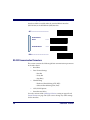
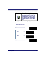
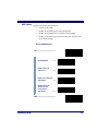
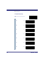
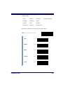
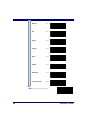
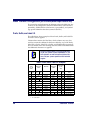
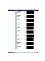
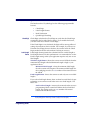
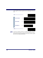
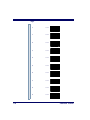
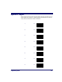
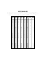
Symbologies Supported
Symbology selection (bar code type) determines which symbologies
the scanner will decode. The chart below shows the symbologies that
are supported by each interface. Once you have identified the symbologies you wish to enable, turn to the following pages, enable those symbologies and set the data format options (e.g. check digit, start/stop
characters) required by your host system for each symbology type.
You must enable the symbology format options settings that are compatible with your host system.
The factory settings for each interface were chosen to meet the standard industry requirements and in most cases you will not need to
change the symbology format settings. If you are unsure of your system requirements, test the scanner using the factory settings before
making any changes.
= Supports this symbology
INTERFACE TYPE
RS-232-STD
WN*-RS-232
Wand Emulation
Keyboard Wedge
Code 39/PharmaCode
Code128
EAN 128
Interleaved 2 of 5
Codabar
UPC-A & E, EAN-13 & 8
UPC/EAN w/P2 Add-ons
UPC/EAN w P5 Add-ons
UPC/EAN w/C128 Add-ons
Code 93
Standard 2 of 5/IATA
MSI/Plessey
SYMBOLOGIES SUPPORTED
(all subtypes)
IBM Port 5B
IBM Port 9B
IBM Port 17
IBM Port E
*Wincor Nixdorf
62
PowerScan® Scanner
Symbology Overview
This section provides a brief descriptions of each of the many symbology features and options available.
Enable Code 39 - selects Code 39 as an active symbology and allows
selection of Check Digit, Start/Stop and Single Digit options.
Enable PharmaCode 39 - is a symbology subset of Code 39. Enabling
PharmaCode 39 allows the scanner to read both PharmaCode 39 and
Standard Code 39 labels.
Standard Code 39 must be enabled before
PharmaCode can be enabled.
NOTE
Enable Code 128 - selects Code 128 as an active symbology. The scanner is preset to recognize all Code 128 bar codes that have between
1 and 50 characters.
Enable UCC/EAN 128 - chooses EAN 128 as an active symbology. The
Automatic Identification Manufacturers, Inc. of the United States (AIM
USA) have standardized the reporting of data sources from bar code
reading devices. Sending the AIM symbology prefix identifies the
symbology to the host terminal, allowing it to specifically differentiate
between UCC/EAN-128 (Code 128 with Function Character 1 in the
first position) and standard Code 128 symbols. When this feature is
disabled, the host cannot differentiate between these symbols.
Enable Interleaved 2 of 5 - selects Interleaved 2 of 5 as an active symbology. Allows change of Check Digit or label format (fixed or variable
length) options.
Enable Codabar - selects Codabar as an active symbology. Allows
selection of Check Digit, Start/Stop character and format, or label format (fixed or variable length) options.
Enable UPC-A - enables UPC-A as an active symbology. If you enable
this symbology, additional options for symbology expansion and reading add-ons are available.
Enable UPC-E - tells the scanner to recognize UPC-E as an active symbology. Like UPC-A, UPC-E offers options for symbology expansion
and reading of add-ons.
Programming Guide
63
Enable EAN-13 - selects EAN-13 as an active symbology. EAN-13
options are similar to those of the EAN-8 symbology.
Enable EAN-8 - selects EAN-8 as an active symbology. EAN-8 symbology selection also allows options for symbology expansion and reading
of add-ons.
Enable Code 93 - enables Code 93 as an active symbology. The scanner
is preset to recognize all Code 93 bar codes that have between 1 and 50
characters.
Enable Standard 2 of 5 - selects Standard 2 of 5 as an active symbology.
Options for this symbology are similar to Interleaved 2 of 5
features.
IATA - is a special symbology subset of Standard 2 of 5. Enabling IATA
selects this custom code as the active Standard 2 of 5 symbology
(superseding any other Standard 2 of 5 features).
Standard 2 of 5 must be enabled in order for
IATA to be active, however, when IATA is
enabled, Standard 2 of 5 will not be decoded.
NOTE
Enable MSI/Plessey - selects MSI/Plessey as an active symbology.
Allows selection of Check Digit or label format (fixed or variable
length) options.
64
PowerScan® Scanner
Symbology Selection
The bar code programming labels on the following pages allow you to
enable specific symbologies or disable all symbologies.
NOTE
If you enable a symbology that has additional
features that should be set, turn to the pages
that support that symbology and its programmable features.
SET -------------------------------------------
NOTE
To optimize your scanner’s performance, first
disable all symbologies by scanning the DISABLE ALL SYMBOLOGIES bar code, then
enable ONLY those symbologies required by
your site.
Disable all Symbologies ---------
Symbology Selections
Programming Guide
Enable Code 39
---------
Enable
PharmaCode 39a
---------
65
66
Enable Code 128
---------
Enable UCC/EAN 128
---------
Enable Interleaved
2 of 5
---------
Enable Codabar
---------
Enable UPC-A
---------
Enable UPC-E
---------
Enable EAN-13
---------
Enable EAN-8
---------
Enable Code 93
---------
PowerScan® Scanner
Enable Standard 2 of 5
---------
Enable IATAb
---------
Enable MSI/Plessey
---------
END ------------------------------------------
a. Code 39 must first be enabled for the scanner to read PharmaCode 39
labels.
b. Standard 2 of 5 must first be enabled for IATA to be active, however, when
IATA is enabled, Standard 2 of 5 will not be decoded.
Programming Guide
67
Symbology Options
After enabling the desired symbology, you can use the bar codes labels
in this section to configure the specific options/features required for
your site.
Code 39/PharmaCode 39
Code 39 The Code 39 symbology has the following programmable features:
Options
• Check Digit
•
Start/Stop Characters
•
Code 39 Full ASCII
•
Minimum Label Length
•
Read Verification
•
QuadraLogic Decoding
Check Digit
Check Digit calculates the Check Digit to verify that the Check Digit
contained in the bar code label is correct. If you enable this feature,
your bar codes must contain a Check Digit.
Start/Stop
Characters
Start/Stop Characters selects either Send or Don’t Send depending on
your host’s interface requirement.
Code 39 Full
ASCII
Code 39 Full ASCII enables or disables the ability to decode Code 39
Full ASCII labels.
Minimum Label
Length
Minimum Label Length sets the minimum label length required for the
Code 39 symbology. This feature causes the scanner to ignore small
label segments, reducing the possibility that a portion of a good label is
incorrectly seen as an entire label.
Read Verification
Read Verification is the number of times the scanner is required to read
the bar code data before sending the label data to the host.
QuadraLogic
Decoding
QuadraLogic Decoding directs the scanner to decode labels with widespread problems of spots, voids, and/or non-uniform widths.
To optimize your scanner’s performance activate this option only for
symbologies for which it is necessary.
There are many additional ways to configure the scanner to read and
decode extremely poor labels. Contact your sales representative or service provider for other advanced QuadraLogic Decoding settings.
68
PowerScan® Scanner
Configuring Use the special bar codes in this section to configure the Code 39
the Code 39 options
Options
SET ------------------------------------------
Check Digit
Don’t Calculate
---------
Calculate
---------
Don’t Transmit
---------
Transmit
---------
Start/ Stop
Programming Guide
Don’t Transmit
---------
Transmit
---------
69
Code 39 Full ASCII
Enable
---------
Disable
---------
END ------------------------------------------
70
PowerScan® Scanner
Minimum Label
Length
Follow these steps to set Code 39 Minimum Label Length:
1.
Identify the minimum label length setting you want to make.
The selectable range is 00 to 481 characters.
2.
Scan the SET bar code.
3.
Scan the SET MINIMUM LABEL LENGTH bar code.
4.
Set the minimum label length by scanning the applicable
digits from the bar codes on page 72. Return to this page and
go to step five.
If you are setting a label length less than ten,
you must scan a zero digit first and then the
length digit (e.g., 04, 06, 08).
NOTE
5.
Scan the END barcode.
Minimum Label Length
SET ------------------------------------------
Set Minimum Label
Length
---------
END ------------------------------------------
1. For this symbology, the scanner will decode up to 48 characters, but the actual length read will
vary depending upon interface type, and bar code physical size and quality. Code 39 bar codes
containing one or more full ASCII characters can also limit the amount of characters that will be
decoded (in these circumstances, the scanner will decode at least 24 data characters).
Programming Guide
71
Digits
72
0
---------
1
---------
2
---------
3
---------
4
---------
5
---------
6
---------
7
---------
8
---------
9
---------
PowerScan® Scanner
Read Verification
Scan the bar codes below to set the minimum number of reads required
to verify Code 39/Pharmacode 39 symbologies.
NOTE
The more times the scanner is required to
read and compare the bar codes data, the
longer the scanner will take to validate and
transmit a label.
SET ------------------------------------------
Set to One read
---------
Set to Two reads
---------
Set to Three reads
---------
Set to Four reads
---------
END ------------------------------------------
Programming Guide
73
QuadraLogic
Decoding
Scan these bar codes to activate/deactivate the QuadraLogic Decoding
feature for Code 39/PharmaCode 39 symbologies.
SET ------------------------------------------
Activate for Code 39/
PharmaCode 39
---------
Deactivate for Code 39/
PharmaCode 39
---------
END ------------------------------------------
PharmaCode PharmaCode 39 symbology has the following programmable features:
39 Options
• Transmit Check Digit
•
Transmit Check
Digit
Start/Stop
Characters
Start/Stop Characters
Transmit Check Digit selects whether the Check Digit will/won’t be
transmitted to the host terminal.
Start/Stop Characters directs the scanner to either Send or Don’t Send
depending on your host’s interface requirement.
NOTE
74
In order for PharmaCode 39 labels to be read
and transmitted as PharmaCode 39, the Code
39 symbology must first be enabled.
PowerScan® Scanner
Configuring Scan the bar codes below to configure the PharmaCode 39 options for
the Check Digit and Start/Stop Characters.
PharmaCode
39 Options
SET ------------------------------------------
Check Digit
Don’t Transmit
---------
Transmit
---------
Start/Stop
Don’t Transit
---------
Transmit
---------
END ------------------------------------------
Programming Guide
75
Code128 and UCC/EAN 128 Options
The Code 128 and UCC/EAN 128 symbologies have the following programmable feature.
•
Minimum Label Length
•
Read Verification
•
QuadraLogic Decoding
Setting Minimum
Label Length
Setting Minimum Label Length sets the minimum length required for
Code 128 and UCC/EAN symbology. This feature causes the scanner
to ignore small label segments, reducing the possibility that a portion
of a good label is incorrectly seen as an entire label.
Read Verification
Read Verification is the number of times the scanner is required to read
the bar code data before sending the label data to the host.
QuadraLogic
Decoding
QuadraLogic Decoding directs the scanner to decode labels with widespread problems of spots, voids, and/or non-uniform widths.
To optimize your scanner’s performance activate this option only for
symbologies for which it is necessary.
There are many additional ways to configure the scanner to read and
decode extremely poor labels. Contact your sales representative or service provider for other advanced QuadraLogic Decoding settings.
76
PowerScan® Scanner
Configuring Use the bar codes in this section to configure the Code 128 and UCC/
the Code 128/ EAN 128 options.
and UCC/EAN
128 Options
Minimum Label
Length
Follow these steps to set Code 128 and UCC/EAN 128 Minimum Label
Length.
1.
Identify the minimum length setting you want to make. The
selectable range is 00 to 801 characters.
2.
Scan the SET bar code on page 77.
3.
Scan the SET MINIMUM LABEL LENGTH bar code.
4.
Set the minimum label length by scanning the applicable
digits from the bar codes on page 78. Return to this page and
go to step five
If you are setting a label length less than ten,
you must scan a zero digit first and then the
length digit (e.g., 04, 06, 08).
NOTE
5.
Scan the END bar code
Minimum Label Length
SET ------------------------------------------
Set Minimum Label Length ---------
END ------------------------------------------
1. The scanner will decode up to 80 characters, but the actual length read will vary depending upon
interface type, the physical size of the bar codes, print quality and whether the bar code data consists of Code 128 code set A, set B, or set C characters. (The C128 character set C allows for
more densely packed data, thus if the bar code includes all or mostly C128 set C characters, more
characters can be decoded).
Programming Guide
77
Digits
78
0
---------
1
---------
2
---------
3
---------
4
---------
5
---------
6
---------
7
---------
8
---------
9
---------
PowerScan® Scanner
Read Verification
Scan the bar codes below to set the minimum number of reads required
to verify Code 128 and UCC/EAN symbologies.
NOTE
The more times the scanner is required to
read and compare the bar codes data, the
longer the scanner will take to validate and
transmit a label.
SET ------------------------------------------
Set to One read
---------
Set to Two reads
---------
Set to Three reads
---------
Set to Four reads
---------
END ------------------------------------------
Programming Guide
79
QuadraLogic
Decoding
Scan these bar codes to activate/deactivate the QuadraLogic Decoding
feature for the Code 128 and UCC/EAN 128 symbologies.
SET ------------------------------------------
Activate for C128 and
UCC/EAN 128
---------
Deactivate for C128 and
UCC/EAN 128
---------
END ------------------------------------------
80
PowerScan® Scanner
Interleaved 2 of 5 Options
The Interleaved 2 of 5 symbology has the following programmable
features:
Check Digit
•
Check Digit
•
Label Length Format
•
Read Verification
•
QuadraLogic Decoding
Check Digit calculates the Check Digit to verify that the Check Digit
contained in the bar code label is correct. If you enable this feature,
your bar codes must contain a Check Digit.
If the Check Digit is not calculated, the digit will be sent regardless of
settings for transmit or don’t transmit. For example, if you choose to
Transmit Check Digit, but not calculate, the scanner sends the Check
Digit encoded in the bar code without verifying its accuracy.
Label Length
Format
Label length format permits the selection between variable length or
fixed length formats. For best performance it is recomended to use the
Fixed Length settings when your application requires only one or two
label lengths.
Variable Length Format - directs the scanner to read all labels from the
minimum label length to 50. Set Minimum Length as high as your
application allows.
Minimum Label Length - selects the minimum label length
that the scanner will recognize. The minimum label length for
this symbology must be an even number of characters between
02 and 501.
Fixed length Format - directs the scanner to read only one or two label
lengths.
If you select fixed length format, there are three bar code labels for programming your scanner to read either one or two fixed lengths. The
labels are:
Set First Fixed Length - instructs the scanner that the next two
programming labels scanned will define the first fixed label
length. This setting can be any even number of characters
between 02 and 501 characters.
1. For this symbology, the scanner will decode up to 50 characters, but the actual length read will
vary depending upon the interface type, and bar code physical size and quality.
Programming Guide
81
Set Second Fixed Length - instructs the scanner that the next
two programming labels scanned will define the second fixed
label length. This setting can be any even number of characters
between 02 and 501 characters.
No Second Fixed Length - configures the scanner to recognize
only the first fixed length.
Read Verification
Read Verification is the number of times the scanner is required to read
the bar code data before sending the label data to the host.
QuadraLogic
Decoding
QuadraLogic Decoding directs the scanner to decode labels with widespread problems of spots, void, and/or non-uniform widths.
To optimize your scanner’s performance activate this option only for
symbologies for which it is necessary.
There are many additional ways to configure the scanner to read and
decode extremely poor labels. Contact your sales representative or service provider for other advanced QuadraLogic Decoding settings.
1. For this symbology, the scanner will decode up to 50 characters, but the actual length read will
vary depending upon the interface type, and bar code physical size and quality.
82
PowerScan® Scanner
Configuring Use the special bar codes in this section to configure the Interleaved
the Interleaved 2 of 5 symbology options.
2 of 5 Options
Check Digit
SET ------------------------------------------
Don’t Calculate
---------
Calculate
---------
Don’t Transmit
---------
Transmit
---------
END ------------------------------------------
Programming Guide
83
Label Length
Format
Follow the steps below to set the Interleaved 2 of 5 label Length Format
to select either the Variable Length or Fixed Length Format.
Variable Length
Format
Follow the steps below to set the Interleaved 2 of 5 symbology to Variable Length Format.
1.
Identify the minimum length setting you want to make. The
selectable range is any even number between 02 to 501
characters.
2.
Scan the SET bar code below.
3.
Scan the ENABLE VARIABLE LENGTH FORMAT bar code.
4.
Scan the SET MINIMUM LABEL LENGTH bar code.
5.
Set the minimum label length by scanning the correct digits
from page 87. Return to this page and go to step six.
If you are setting a label length less than ten,
you must scan a zero digit first and then the
length digit (e.g., 04, 06, 08).
NOTE
6.
Scan the END bar code.
Variable Length Format
SET ------------------------------------------
Enable Variable Length
Format
---------
Set Minimum Label
Length
---------
END ------------------------------------------
1. For this symbology, the scanner will decode up to 50 characters, but the actual length read will
vary depending upon the interface type, and bar code physical size and quality.
84
PowerScan® Scanner
Fixed Length
Format
All interfaces that are shipped with the standard factory configuration
are set to read variable length labels. If you switch from the variable to
fixed length format, the default label lengths are 14 characters and 8
digits. All fixed length settings must be an even number.
Follow the steps below to set Interleaved 2 of 5 symbology to Fixed
Length Format.
1.
Identify the fixed length settings you want to make.
2.
Scan the SET bar code.
3.
Scan the ENABLE FIXED LENGTH FORMAT bar code.
4.
Scan the SET FIRST FIXED LENGTH bar code.
5.
Set the first fixed label length by scanning the digit bar codes
from page 87 (even number only). Return to this page.
If you are setting a label length less than ten, you
must scan a zero digit first and then the length
digit (e.g., 04, 06, 08).
NOTE
If you need to set a second fixed length, continue to step six. If you do
not need to set a second fixed length skip to step nine.
6.
Scan the SET SECOND FIXED LENGTH bar code.
7.
Set the second fixed label length by scanning the applicable
digit bar codes from page 87.
8.
Return to this page and go to step ten.
If you are setting a label length less than ten, you
must scan a zero digit first and then the length
digit (e.g., 04, 06, 08).
NOTE
9.
Scan the NO SECOND FIXED LENGTH bar code.
10. Scan the END bar code.
Programming Guide
85
Fixed Length Format
SET ------------------------------------------
Enable Fixed Length
Format
---------
Set First Fixed Length
---------
Set Second Fixed Length ---------
No Second Fixed Length ---------
END ------------------------------------------
86
PowerScan® Scanner
Digits
Programming Guide
0
---------
1
---------
2
---------
3
---------
4
---------
5
---------
6
---------
7
---------
8
---------
9
---------
87
Read Verification
Scan the bar codes below to set the number of reads desired to verify
Interleaved 2 of 5 symbology.
NOTE
The more times the scanner is required to
read and compare the bar codes data, the
longer the scanner will take to validate and
transmit a label.
SET ------------------------------------------
Set to One read
---------
Set to Two reads
---------
Set to Three reads
---------
Set to Four reads
---------
END ------------------------------------------
88
PowerScan® Scanner
QuadraLogic
Decoding
Scan these bar codes to activate/deactivate the QuadraLogic Decoding
feature for Interleaved 2 of 5 symbology.
SET ------------------------------------------
Activate for Interleaved
2 of 5
---------
Deactivate for Interleaved
2 of 5
---------
END ------------------------------------------
Programming Guide
89
Codabar Options
The Codabar symbology has the following programmable features:
Check Digit
•
Check Digit
•
Gap Check
•
Label Length Format
•
Start/Stop Character
•
Start/Stop Match
•
Start/Stop Format
•
Read Verification
•
QuadraLogic Decoding
Check Digit calculates the Check Digit to verify the label’s contents
have been read correctly. If you enable this feature, your labels must
include a Check Digit. You may also choose to transmit or not transmit
the Check Digit.
If the Check Digit is not calculated, the digit will be sent regardless of
settings for transmit or don’t transmit. For example, if you choose to
Transmit Check Digit, but not calculate, the scanner sends the Check
Digit encoded in the label without verifying its accuracy.
Gap Check
Disabling Gap Check allows the scanner to combine two label halves
printed in close proximity to each other that may have been printed at
different times and perhaps different locations.
Label Length
Format
Label length format permits the selection between variable length or
fixed length formats. For best performance it is recomended to use the
Fixed Length settings when your application requires only one or two
label lengths.
Variable Length Format - directs the scanner to read all labels from
minimum label length to 50. Set Minimum Length as high as your
application allows.
Minimum Label Length - selects the minimum label length
that the scanner will recognize. The minimum label length for
this symbology must be between 03 and 501.
Fixed length Format - directs the scanner to read only one or two label
lengths.
1. For this symbology, the scanner will decode up to 50 characters, but the actual length read will
vary depending upon the interface type, and bar code physical size and quality.
90
PowerScan® Scanner
If you select fixed length format, there are three bar code labels for programming your scanner to read either one or two fixed lengths. The
labels are:
Set First Fixed Length - instructs the scanner that the next two
programming labels scanned will define the first fixed label
length. This setting must be between 03 and 501 characters.
Set Second Fixed Length - instructs the scanner that the next
two programming labels scanned will define the second fixed
label length. This setting must be between 03 and 501
characters.
No Second Fixed Length - configures the scanner to recognize
only the first fixed length.
Start/Stop
Characters
Start/Stop Match
Start/Stop
Format
Start/Stop Characters can be either Send or Don’t Send depending on
your host’s interface requirement. Refer to your host user’s manual to
identify your system requirements.
Start/Stop Match can be enabled or disabled.
Start/Stop Format can be set to one of four standard format options:
ABCD/TN*E, ABCD/ABCD, abcd/tn*e, or abcd/abcd. This setting
must match your system requirements. If you select one of these
options, it determines how the ASCII characters A, B, C, D (used for
Start/Stop characters) are translated before being sent to the host.
Read Verification
Read Verification is the number of times the scanner is required to read
the bar code data before sending the label data to the host.
QuadraLogic
Decoding
QuadraLogic Decoding directs the scanner to decode labels with widespread problems of spots, voids, and/or non-uniform widths.
To optimize your scanner’s performance activate this option only for
symbologies for which it is necessary.
There are many additional ways to configure the scanner to read and
decode extremely poor labels. Contact your sales representative or service provider for other advanced QuadraLogic Decoding settings.
1. For this symbology, the scanner will decode up to 50 characters, but the actual length read will
vary depending upon the interface type, and bar code physical size and quality.
Programming Guide
91
Configuring Use the special bar codes in this section to configure the Codabar symthe Codabar bology options.
Options
SET ------------------------------------------
Check Digit
Don’t Calculate
---------
Calculate
---------
Don’t Transmit
---------
Transmit
---------
Gap Check
Enable
---------
Disable
---------
END ------------------------------------------
92
PowerScan® Scanner
Label Length
Format
Variable Length
Format
Follow the steps below to set the Codabar label Length Format to select
either the Variable Length or Fixed Length Format.
Follow the steps below to set the Codabar symbology to Variable
Length Format.
1.
Identify the minimum length setting you want to make. The
selectable range is 03 to 501 characters.
2.
Scan the SET bar code below.
3.
Scan the ENABLE VARIABLE LENGTH FORMAT bar code.
4.
Scan the SET MINIMUM LABEL LENGTH bar code.
5.
Set the minimum label length by scanning the correct digits
from page 96. Return to this page and go to step six.
If you are setting a label length less than ten,
you must scan a zero digit first and then the
length digit (e.g., 04, 06, 08).
NOTE
6.
Scan the END bar code.
Variable Length Format
SET ------------------------------------------
Enable Variable Length
Format
---------
Set Minimum Label
Length
---------
END ------------------------------------------
1. For this symbology, the scanner will decode up to 50 characters, but the actual length read will
vary depending upon the interface type, and bar code physical size and quality.
Programming Guide
93
Fixed Length
Format
The scanner offers the option of requiring Codabar labels to have one
or two fixed lengths in the Fixed Label Format. Follow the steps below
to set Codabar symbology to Fixed Length Format.
1.
Identify the fixed length settings you want to make.
2.
Scan the SET bar code.
3.
Scan the ENABLE FIXED LENGTH FORMAT bar code.
4.
Scan the SET FIRST FIXED LENGTH bar code.
5.
Set the first fixed label length by scanning the applicable digit
bar codes from the page 96. Return to this page.
If you are setting a label length less than ten, you
must scan a zero digit first and then the length
digit (e.g., 04, 06, 08).
NOTE
If you need to set a second fixed length, continue with step six. If you
do not need to set a second fixed length skip to step nine.
6.
Scan the SET SECOND FIXED LENGTH bar code.
7.
Set the second fixed label length by scanning the applicable
digits bar codes from the page 96.
8.
Return to this page and go to step ten.
If you are setting a label length less than ten, you
must scan a zero digit first and then the length
digit (e.g., 04, 06, 08).
NOTE
9.
Scan the NO SECOND FIXED LENGTH bar code.
10. Scan the END bar code.
94
PowerScan® Scanner
Fixed Length Format
SET ------------------------------------------
Enable Fixed Length
Format
---------
Set First Fixed Length
---------
Set Second Fixed Length ---------
No Second Fixed Length ---------
END ------------------------------------------
Programming Guide
95
Digits
96
0
---------
1
---------
2
---------
3
---------
4
---------
5
---------
6
---------
7
---------
8
---------
9
---------
PowerScan® Scanner
Start/Stop Characters
SET ------------------------------------------
Match not required
---------
Match Required
---------
Don’t Transmit
---------
Transmit a
(requires Format)
---------
Format = ABCD/TN*E
---------
Format = abcd/tn*e
---------
Format = ABCD/ABCD
---------
Format = abcd/abcd
---------
END ------------------------------------------
a. Choosing Transmit Start/Stop characters requires selecting one of these
four data format selections: ABCD/TN*E, abcd/tn*e, ABCD/ABCD, or
abcd/abcd.
Programming Guide
97
Read Verification
Scan the bar codes below to set the number of reads desired to verify
Codabar symbology.
NOTE
The more times the scanner is required to
read and compare the bar codes data, the
longer the scanner will take to validate and
transmit a label.
SET ------------------------------------------
Set Read to One read
---------
Set to Two reads
---------
Set Read to Three reads ---------
Set to Four reads
---------
END ------------------------------------------
98
PowerScan® Scanner
QuadraLogic
Decoding
Scan these bar codes to activate/deactivate the QuadraLogic Decoding
feature for the Codabar symbology.
SET ------------------------------------------
Activate for Codabar
---------
Deactivate for Codabar
---------
END ------------------------------------------
Programming Guide
99
UPC/EAN Options
The UPC/EAN symbologies have the following programmable
features:
Data Format
Settings
UPC/EAN
Expansion
•
Data Format Settings
•
UPC/EAN Expansion
•
UPC/EAN Add-ons
•
Price/Weight Check Digit
•
Read Verification
•
QuadraLogic Decoding.
UPC/EAN Data Format Settings provides options for transmitting
Check Digits or Number System Digits (NSD).
Expand UPC-A to EAN-13 adds a leading zero to a UPC-A label which
‘expands’ the label to the EAN-13 data format. Selecting this feature
also changes the symbology ID to match those required for
EAN-13.
Expand UPC-E to UPC-A expands UPC-E labels to UPC-A data format.
Selecting this feature also changes the symbology ID to match those
required for UPC-A.
Expand EAN-8 to EAN-13 adds five zeros in front of an EAN-8 label.
Data is sent in EAN-13 data format. Selecting this feature also changes
the symbology ID to match those required for EAN-13.
Expand UPC-E to EAN-13 expands UPC-E labels to EAN-13 data format. Selecting this feature also changes the symbology ID to match
those required for EAN-13.
UPC/EAN
Add-ons
UPC-A or UPC-E and EAN-8 or EAN-13 Two and Five Digit
Add-ons filters
Required means UPC/EAN bar codes must have add-ons or
label will not be read.
Optional means scanner will read UPC/EAN bar codes with
or without add-ons.
Disable directs the scanner not to recognize/read add-on portions of UPC/EAN labels, but will read the main body of the
label.
100
PowerScan® Scanner
Price/Weight
Check Digit
Price/Weight Check Digit provides options for enabling price/weight
check digits. The feature includes selections for domestic four or five
digit, and European four or five digit, as well as the option to disable
the price/weight check.
Read Verification
Read Verification is the number of times the scanner is required to read
the bar code data before sending the label data to the host.
QuadraLogic
Decoding
QuadraLogic Decoding directs the scanner to decode labels with widespread problems of spots, voids, and/or non-uniform widths.
To optimize your scanner’s performance activate this option only for
symbologies for which it is necessary.
There are many additional ways to configure the scanner to read and
decode extremely poor labels. Contact your sales representative or service provider for other advanced QuadraLogic Decoding settings.
Programming Guide
101
Configuring Use the special bar codes in this section to configure the UPC/ EAN
the UPC/EAN options.
Options
UPC Data Format
Settings
These settings affect UPC data format. Number System Digit (NSD)
settings operate with RS-232 and Keyboard Wedge interfaces ONLY.
Scan the bar codes below to send or not send the Check Digit/NSD.
SET ------------------------------------------
UPC-A
102
Send Check Digit
---------
Don’t Send Check Digit
---------
Send NSDa
---------
Don’t Send NSDa
---------
PowerScan® Scanner
UPC-E
Send Check Digitb
---------
Don’t Send Check Digitb ---------
Send NSDb
---------
Don’t Send NSDb
---------
END ------------------------------------------
a. NSD = Number System Digit. The NSD character is the character that
precedes the UPC bar code. The NSD for regular UPC-A bar codes is a
zero. Other commonly used Number System Digits used with UPC-A are:
“2” - used for random weight items such as meat and produce.
“3” - used for the drug and health items.
“4” - used for in-store non-food items.
“5” - used for coupons.
b. If UPC-E is expanded to UPC-A, the transmission of Check Digit (CD)
and NSD will be determined by the UPC-A settings on this page.
Example: UPC-A
w/NSD
Programming Guide
103
EAN Data Format
Settings
These settings affect EAN data format.
SET ------------------------------------------
EAN-13
Send Check Digit
---------
Don’t Send Check Digit
---------
Send NSDa
---------
Don’t Send NSDa
---------
EAN-8
Send Check Digit
---------
Don’t Send Check Digit
---------
END ------------------------------------------
a. NSD = Number System Digit. The NSD character is the character that
precedes the EAN bar code, as in this example.
Example: EAN
with NSD
104
PowerScan® Scanner
UPC/EAN
Expansion
Use these labels to activate:
• Expand UPC-A to EAN-13
• Expand UPC-E to UPC-A
• Expand EAN-8 to EAN-13
• Expand UPC-E to EAN-13
SET ------------------------------------------
UPC-A to EAN-13 Expansion
Expanda
---------
Don’t Expand
---------
UPC-E to UPC-A Expansion
Expanda
---------
Don’t Expand
---------
EAN-8 to EAN-13 Expansion
Programming Guide
Expanda
---------
Don’t Expand
---------
105
UPC-E to EAN-13 Expansion
Expanda
---------
Don’t Expand
---------
END ------------------------------------------
a. When any expansion features is activated, the transmission of the Prefix,
Suffix, Check Digit and Number System Digit (NSD) are controlled by
your selections for the symbology ‘expanded to’ rather than the symbology ‘expanded from’. For example, if you expand OPC-E to UPC-A, settings for UPC-A determine how the scanner sends a bar code’s contents.
106
PowerScan® Scanner
UPC/EAN
Add-ons
There are many ways to configure the scanner to handle add-ons. The
scanner uses four filters that can be specified to define how add-ons
will be handled. The following is true for each filter.
•
Each add-on type can be disabled, required or optional.
•
Any combination of the four UPC/EAN symbologies can be
affected.
•
The 2-digit, 5-digit and C128 add-ons can be individually
configured.
•
The leading digits of the base labels affected can be specified.
NOTE
The settings below represent only a small portion of the options available for this feature.
Contact your sales representative or service
provider if you need more assistance with
advanced add-on settings.
This programming guide supports the following add-on filters for
UPC/EAN:
•
Required means that UPC/EAN labels MUST contain a
2-digit, 5-digit or C128 add-on segment in order for the scanner
to recognize or decode them.
•
Optional directs the scanner to recognize UPC/EAN bar codes
with or without P2, P5 or C128 2-digit add-on segments.
•
Disable Add-ons means the scanner will not recognize or
decode any add-on segment of UPC/EAN labels, but will read
and decode the standard UPC/EAN portion of the label.
NOTE
Programming Guide
Due to the structure of add-on codes, selecting
the optional setting makes it impossible to
ensure that the scanner will always read the
add-on portion of the label. PSC makes no
guarantee, either written or implied, that scanners with optional add-on decoding enabled
will perform with the speed and accuracy
required for any given application.
107
The following bar codes affect all four UPC/EAN symbologies, and
will be applied to all labels regardless of the leading digits of the base
label.
SET ------------------------------------------
Add-ons Required
---------
Add-ons Option
---------
Disable Add-ons
---------
END ------------------------------------------
Custom
Add-ons
108
A wide array of add-on options are available to streamline your installation to its best advantage. Call your sales representative or service
provider for assistance in customizing your scanner’s add-on capabilities to your own unique specifications.
PowerScan® Scanner
Price/Weight
Check Digit
The price/weight check digit selections allow you to specify whether
the scanner should calculate an extra check digit based on a four or
five-digit price/weight block and compare it with the price/weight
check digit contained in the bar code. If the calculated check digit does
not match the value of the check digit contained in the bar code, the
label will be rejected as invalid. Select domestic four or five digit,
European four or five digit, or disable the price/weight check.
SET ------------------------------------------
Disable P/W Check
---------
Enable 4-Digit Check
---------
Enable 5-Digit
---------
Enable Euro 4-Digit
---------
Enable Euro 5-Digit
---------
END ------------------------------------------
Programming Guide
109
Read Verification
Follow the steps below to set the number of minimum reads required
to verify UPC/EAN symbologies.
To set the minimum read requirement for a desired symbology:
1.
Scan the SET bar code.
2.
Scan one symbology label from the list below to be
verified.
3.
Scan the bar code on page 111 that represents the number of
times you wish a bar codes label of that symbology type to be
read before transmission to the host from the list.
4.
Repeat steps two through three above until read verification
has been modified for each of the the desired symbologies.
5.
Scan the END bar code on page 111.
Read Verification
SET --------------------------------------
110
Verify UPC-A
---------
Verify UPC-E
---------
Verify EAN-13
---------
Verify EAN-8
---------
Verify Instore Label
---------
PowerScan® Scanner
Number of Reads to Verify
One Read
---------
Two Reads
---------
Three Reads
---------
Four Reads
---------
END ------------------------------------------
QuadraLogic
Decoding
Scan these bar codes to activate/deactivate the QuadraLogic Decoding
feature for the UPC/EAN symbologies.
NOTE
To optimize your scanner’s performance activate this option only for symbologies for which
it is necessary.
SET ------------------------------------------
Activate for UPC-A/
EAN-13
Programming Guide
---------
111
Deactivate for UPC-A/
EAN-13
---------
Activate for UPC-E
---------
Deactivate for UPC-E
---------
Activate for EAN-8
---------
Deactivate for EAN-8
---------
END ------------------------------------------
Code 93 Options
The Code 93 symbology has the following programmable features:
112
•
Minimum Label Length
•
Read Verification
Minimum Label
Length
Minimum Label Length sets the minimum label length required for
Code 93 symbology. This feature causes the scanner to ignore small
label segments, reducing the possibility that a portion of a good label is
incorrectly seen as an entire label.
Read Verification
Read Verification is the number of times the scanner is required to read
the bar code data before sending the label data to the host.
PowerScan® Scanner
Configuring Use these special bar codes to configure the Code 93 options.
the Code 93
Options
Minimum Label
Length
1.
Identify the minimum length setting you want to make. The
selectable range is 01 to 501 characters.
2.
Scan the SET bar code.
3.
Scan the SET MINIMUM LABEL LENGTH bar code.
4.
Set the minimum label length by scanning the applicable digits
from page 114. The range is 01 to 501 characters. Return to this
page and go to step five.
If you are setting a label length less than ten, you
must scan a zero digit first and then the length
digit (e.g., 04, 06, 08).
NOTE
5.
Scan the END bar code.
SET ------------------------------------------
Set Minimum Label
Length
---------
END ------------------------------------------
1. For this symbology, the scanner will decode up to 50 characters, but the actual length read will
vary depending upon interface type, and bar code physical size and quality. The IBM POS interface is limited to 32 character labels. Code 93 bar codes containing one or more shift characters
can also limit the amount of characters that will be decoded (in these circumstances, the scanner
will decode at least 39 data characters).
Programming Guide
113
Digits
114
0
---------
1
---------
2
---------
3
---------
4
---------
5
---------
6
---------
7
---------
8
---------
9
---------
PowerScan® Scanner
Read Verification
Scan the bar codes below to set the number of reads desired to verify
Code 93 symbology.
NOTE
The more times the scanner is required to
read and compare the bar codes data, the
longer the scanner will take to validate and
transmit a label.
SET ------------------------------------------
Set to One read
---------
Set to Two reads
---------
Set to Three reads
---------
Set to Four reads
---------
END ------------------------------------------
Programming Guide
115
Standard 2 of 5/IATA Options
The Standard 2 of 5/IATA symbologies have the following programmable features:
Check Digit
•
Check Digit
•
Label Length Format
•
Read Verification
Check Digit calculates the Check Digit to verify that the Check Digit
contained in the bar code label is correct. If you enable this feature,
your bar codes must contain a Check Digit.
If the Check Digit is not calculated, the digit will be sent regardless of
settings for transmit or don’t transmit. For example, if you choose to
Transmit Check Digit, but not calculate, the scanner sends the Check
Digit encoded in the bar code without verifying its accuracy.
Label Length
Format
Label length format permits the selection between variable length or
fixed length formats. For best performance it is recomended to use the
Fixed Length settings when your application requires only one or two
label lengths.
Variable Length Format - directs the scanner to read all labels from the
minimum label length to 50. Set Minimum Length as high as your
application allows.
Minimum Label Length - selects the minimum label length
that the scanner will recognize. The minimum label length for
this symbology must be between 01 and 501.
Fixed length Format - directs the scanner to read only one or two label
lengths.
If you select fixed length format, there are three bar code labels for programming your scanner to read either one or two fixed lengths. The
labels are:
Set First Fixed Length - instructs the scanner that the next two
programming labels scanned will define the first fixed label
length. This setting must be between 01 and 501 characters.
Set Second Fixed Length - instructs the scanner that the next
two programming labels scanned will define the second fixed
label length. This setting must be between 01 and 501
characters.
1. For this symbology, the scanner will decode up to 50 characters, but the actual length read will
vary depending upon the interface type, and bar code physical size and quality.
116
PowerScan® Scanner
No Second Fixed Length - configures the scanner to recognize
only the first fixed length.
Read Verification
Read Verification is the number of times the scanner is required to read
the bar code data before sending the label data to the host.
Configuring Use the special bar codes in this section to configure the Standard
the Standard 2 2 of 5/IATA symbology options.
of 5 Options
Check Digit
SET ------------------------------------------
Don’t Calculate
---------
Calculate
---------
Don’t Transmit
---------
Transmit
---------
END ------------------------------------------
Programming Guide
117
Label Length
Format
Variable Length
Format
Follow the steps below to set the Standard 2 of 5/IATA label length format to select either Variable Length or Fixed Length format.
Follow the steps below to set the Standard 2 of 5/IATA symbology to
read Variable Length Format.
1.
Identify the minimum length setting you want to make. The
selectable range is 02 to 501 characters.
2.
Scan the SET bar code below.
3.
Scan the ENABLE VARIABLE LENGTH FORMAT bar code.
4.
Scan the SET MINIMUM LABEL LENGTH bar code.
5.
Set the minimum label length by scanning the applicable digits
on page 121. Return to this page and go to step six.
If you are setting a label length less than ten, you
must scan a zero digit first and then the length
digit (e.g., 04, 06, 08).
NOTE
6.
Scan the END bar code.
Variable Length Format
SET ------------------------------------------
Enable Variable Length
Format
---------
Set Minimum Label
Length
---------
END ------------------------------------------
1. For this symbology, the scanner will decode up to 50 characters , but the actual length read will
vary depending upon the interface type, and bar code physical size and quality.
118
PowerScan® Scanner
Fixed Length
Format
All interfaces that are shipped with the standard factory configuration
are set to read variable length labels. If you switch from variable length
to fixed length format, the default fixed labels are 14 characters and 8
digits. Follow the steps below to change these defaults for the Standard
2 of 5/IATA symbology.
1.
Identify the fixed length settings you want to make.
2.
Scan the SET bar code.
3.
Scan the ENABLE FIXED LENGTH FORMAT bar code .
4.
Scan the SET FIRST FIXED LENGTH bar code.
5.
Set the first fixed label length by scanning the applicable
digits bar codes on page 121. Return to this page.
If you are setting a label length less than ten, you
must scan a zero digit first and then the length
digit (e.g., 04, 06, 08).
NOTE
If you need to set a second fixed length, continue with step six. If you
do not need to set a second fixed length skip to step nine.
6.
Scan the SET SECOND FIXED LENGTH bar code.
7.
Set the second fixed label length by scanning the applicable
digits bar codes on page 121.
8.
Return to this page and go to step ten.
If you are setting a label length less than ten, you
must scan a zero digit first and then the length
digit (e.g., 04, 06, 08).
NOTE
9.
Scan the NO SECOND FIXED LENGTH bar code.
10. Scan the END bar code.
Programming Guide
119
Fixed Length Format
SET ------------------------------------------
Enable Fixed Length
Format
---------
Set First Fixed Length
---------
Set Second Fixed Length ---------
No Second Fixed Length ---------
END ------------------------------------------
120
PowerScan® Scanner
Digits
Programming Guide
0
---------
1
---------
2
---------
3
---------
4
---------
5
---------
6
---------
7
---------
8
---------
9
---------
121
Read Verification
Scan the bar codes below to set the number of reads desired to verify
Standard 2 of 5/IATA symbologies.
NOTE
The more times the scanner is required to
read and compare the bar codes data, the
longer the scanner will take to validate and
transmit a label.
SET ------------------------------------------
Set to One read
---------
Set to Two reads
---------
Set to Three reads
---------
Set to Four reads
---------
END ------------------------------------------
122
PowerScan® Scanner
IATA
IATA is a special symbology subset of Standard 2 of 5. Enabling IATA
selects this custom code as the active Standard 2 of 5 symbology. When
IATA is enabled, Standard 2 of 5 labels will not be read. Scan the bar
code labels below to enable/disable IATA.
SET ------------------------------------------
Enable
---------
Disable
---------
END ------------------------------------------
Programming Guide
123
MSI/Plessey Options
The MSI/Plessey symbology has the following programmable
features:
Check Digit
•
Check Digit
•
Label Length Format
•
Read Verification
Check Digit calculates the Check Digit(s) to verify the labels contents
have been read correctly. If you enable this feature, your bar codes
must include a Check Digit(s). You may also choose to transmit or not
transmit the Check Digit(s).
Check Digit Calculation - enables or disables calculation of
the Check Digit(s).
Transmit Check Digit - enables or disables transmission of
MSI/Plessey Check Digit(s).
Number of Check Digits - specifies either one or two Check
Digits.
Label Length
Format
Label length format permits the selection between variable length or
fixed length formats. For best performance it is recomended to use the
Fixed Length settings when your application requires only one or two
label lengths.
Variable Length Format - directs the scanner to read all labels from the
minimum label length to 16. Set Minimum Length as high as your
application allows.
Minimum Label Length - selects the minimum label length
that the scanner will recognize. The minimum label length for
this symbology must be between 04 and 16.
Fixed Length Format - directs the scanner to read only one or two label
lengths.
If you select fixed length format, there are three bar code labels for programming your scanner to read either one or two fixed lengths. The
labels are:
Set First Fixed Length - instructs the scanner that the next two
programming labels scanned will define the first fixed label
length. This setting must be between 04 and 16 characters.
124
PowerScan® Scanner
Set Second Fixed Length - instructs the scanner that the next
two programming labels scanned will define the second fixed
label length. This setting must be between 04 and 16
characters.
No Second Fixed Length - configures the scanner to recognize
only the label length chosen as the first fixed length.
Read Verification
Programming Guide
Read Verification is the number of times the scanner is required to read
the bar code data before sending the label data to the host.
125
Configuring Use the special bar codes in this section to configure the MSI/Plessey
the MSI / symbology options.
Plessey
Check Digit
Options
SET ------------------------------------------
Calculate
---------
Don’t Calculate
---------
Transmit
---------
Don’t Transmit
---------
One Check Digit
---------
Two Check Digits
---------
END ------------------------------------------
126
PowerScan® Scanner
Label Length
Format
Variable Length
Format
Follow the steps below to set the MSI/Plessey label length format to
either the Variable Length or Fixed Length format.
Follow the steps below to set the MSI/Plessey to read Variable Length
Format.
1.
Identify the minimum length setting you want to make. The
selectable range is 04 to 16 characters.
2.
Scan the SET bar code.
3.
Scan the ENABLE VARIABLE LENGTH FORMAT bar code.
4.
Scan the SET MINIMUM LABEL LENGTH bar code.
5.
Set the minimum label length by scanning the applicable digits
bar codes on page 130. Return to this page.
If you are setting a label length less than ten, you
must scan a zero digit first and then the length
digit (e.g., 04, 06, 08).
NOTE
6. Scan the END bar code.
Variable Length
SET ------------------------------------------
Enable Variable Length
Format
---------
Set Minimum Label
Length
---------
END ------------------------------------------
Programming Guide
127
Fixed Length
Format
The scanner offers the option of requiring MSI/Plessey labels to have
one or two fixed length(s) in the Fixed Label Format. Follow the steps
below to set the MSI/Plessey symbology to fixed length format.
1.
Identify the fixed length setting(s) you wish to make. Fixed
lengths can be set from 04 to 16 characters.
2.
Scan the SET bar code on page 129.
3.
Scan the ENABLE FIXED LENGTH FORMAT bar code.
4.
Scan the SET FIRST FIXED LENGTH bar code.
5.
Set the first fixed label length by scanning the applicable digits
on page 130. Return to this page.
If you are setting a label length less than ten, you
must scan a zero digit first and then the length
digit (e.g., 04, 06, 08).
NOTE
If you need to set a second fixed length, continue with step six. If you
do not need a second fixed length skip to step nine.
6.
Scan the SET SECOND FIXED LENGTH bar code.
7.
Set the second fixed label length by scanning the applicable
digits on page 130.
8.
Return to this page and go to step ten.
If you are setting a label length less than ten, you
must scan a zero digit first and then the length
digit (e.g., 04, 06, 08).
NOTE
9.
Scan the NO SECOND FIXED LENGTH bar code.
10. Scan the END bar code on page 129.
128
PowerScan® Scanner
Fixed Length
SET ------------------------------------------
Enable FIxed Length
Format
---------
Set First Fixed Length
---------
Set Second Fixed Length ---------
No Second Fixed
Length
---------
END ------------------------------------------
Programming Guide
129
Digits
130
0
---------
1
---------
2
---------
3
---------
4
---------
5
---------
6
---------
7
---------
8
---------
9
---------
PowerScan® Scanner
Read Verification
Scan the bar codes below to set the number of reads desired to verify
MSI/Plessey symbologies.
NOTE
The more times the scanner is required to
read and compare the bar codes data, the
longer the scanner will take to validate and
transmit a label.
SET ------------------------------------------
Set to One read
---------
Set to Two reads
---------
Set to Three reads
---------
Set to Four reads
---------
END ------------------------------------------
Programming Guide
131
General Features
The following section contains the general features that are common to
all interfaces. These features allow modification of the scanner's behavior to accommodate user preferences.
•
Green LED Lamp Idle State
•
Beeper Settings
•
Marker Beam Settings
•
AutoSense® Stand Mode
•
Low Power Mode
•
Low Power Shut-down Delay
•
Half-Angle
•
Multiple Read Mode
Programming the General Features
Use the special bar codes on the following pages to configure the features common to all interfaces.
Green LED When the scanner is idle, its green LED lamp can be programmed to
Lamp Idle indicate this in one of two ways:
State
• LED lamp is OFF when the scanner is idle.
•
LED lamp is ON when the scanner is idle.
SET -------------------------------------------
LED OFF
---------
LED ON
---------
END ------------------------------------------
132
PowerScan® Scanner
Beeper These labels provide options for the scanner's audible 'beep' signal.
Settings Reference LED and Beeper Indicators on page 11 for more information
about beeper behavior.
Audible Signal - enables/disables the beep upon completion of a good
read.
NOTE
It is strongly recommended that this feature
remain enabled, as the good read beep provides the best scanning status feedback to the
user. Error tones are always enabled and cannot be disabled.
Power-up Beep - enables/disables the audible tone at power-up.
Beeper Volume - allows setting of the beeper to three different volume
settings. The greatest volume occurs with frequency set high and volume set to 3.
Good Read Beeper Frequency - adjusts the pitch of the beeper to low,
medium, or high.
Good Read Beep Duration - can be adjusted to SHORT (100msec),
MEDIUM (250msec), or LONG (500msec) durations.
When to Beep - may be programmed to announce a 'good read' upon
completion of one of the following events:
Configuring
the Beeper
Options
Programming Guide
•
Decode of a bar code label.
•
Transmission of data from the scanner to the host.
•
CTS activation at the host terminal (RS-232 interface models
ONLY).
Scan these bar codes to set the beeper options.
1.
Scan the SET bar code.
2.
Scan the bar code(s) for option(s) desired.
3.
Scan the END bar code on page 135.
133
SET -------------------------------------------
Beeper Signal
Beeper OFF
---------
Beeper ON
---------
Power-up Beeper
Enable
---------
Disable
---------
Beeper Volume
134
Volume 1
---------
Volume 2
---------
Volume 3
---------
PowerScan® Scanner
Good Read Beep Frequency
Low
---------
Medium
---------
High
---------
Good read Beep Duration
Short
---------
Medium
---------
Long
---------
When to Beep
After Decode
---------
After Transmission to
Host
---------
After CTS Activation
(RS-232 ONLY)
---------
END ------------------------------------------
Programming Guide
135
Marker Beam The Marker Beam feature provides the user with a spotter beam for
Settings improved aiming at distant bar code labels and/or in extremely bright
environments. A Marker Beam can also be useful when scanning
through showcase glass or bar code menus containing bar codes
printed with little space between them.
To enable the Marker Beam:
1.
Scan the SET bar code.
2.
Scan the ENABLE MARKER BEAM bar code.
3.
Scan the desired time duration setting for the Marker Beam to
be illuminated.
4.
Scan the END bar code on page 137.
SET -------------------------------------------
Marker Beam Enable/Disable
Marker Beam Enabled
---------
Marker Beam Disabled
---------
Marker Beam Duration
136
0 Seconds
---------
0.2 Seconds
---------
0.3 Seconds
---------
PowerScan® Scanner
0.4 Seconds
---------
0.5 Seconds
---------
0.6 Seconds
---------
0.8 Seconds
---------
1 Seconds
---------
1.2 Seconds
---------
1.5 Seconds
---------
END ------------------------------------------
Programming Guide
137
AutoSense® AutoSense® Stand Mode must be enabled when the scanner is used
Stand Mode with its stand accessory. This feature allows "hands-free" operation of
the scanner when placed in the stand.
Scan these bar codes to set the AutoSense® option.
1.
Scan the SET bar code.
2.
Scan the bar code to enabel/disable the option.
3.
Scan the END bar code.
SET ------------------------------------------
Enable
---------
Disable
---------
END ------------------------------------------
138
PowerScan® Scanner
Low Power When enabled, Low Power Mode causes the scanner to powerdown
Mode completely between trigger pulls. This results in very low idle current,
lowering the energy needs of the scanner. It does, however, require the
scanner's microcontroller to reboot with every trigger pull. This will
introduce a very small delay in scanning when this mode is enabled.
Therefore, it is recommended that this mode only be used when the
scanner is connected to a battery powered terminal.
NOTE
The state of this feature is not affected by the
RETURN TO FACTORY DEFAULTS programming bar code. It must be manually enabled
or disabled using the programming bar codes
below.
Scan these labels to enable and set the Low Power Mode.
SET ------------------------------------------
Enable Step #1
---------
Enable Step #2
---------
Disable Step #1
---------
Disable Step #2
---------
END ------------------------------------------
Programming Guide
139
Low Power This feature allows for quick successive reads in the Low Power Mode.
Shut-down Low Power Shut-down Delay (LPSD) is the amount of delay after the
Delay trigger is released before the scanner transitions into shut-down. The
programming bar codes below provide for transition times of 0 (no
delay), 2, 5, or 10 seconds delay.
For other LPSD settings contact your sales or service representative.
Scan these bar codes to set the LPSD option.
1.
Scan the SET bar code.
2.
Scan the bar code for delay desired.
3.
Scan the END bar code.
SET ------------------------------------------
0 Seconds (No Delay)
---------
2 Seconds
---------
5 Seconds
---------
10 Seconds
---------
END ------------------------------------------
140
PowerScan® Scanner
Half-Angle When enabled, the Half-Angle feature causes the scanner to scan with
a scan angle that is approximately half the standard setting. Disabling
the feature returns the scanner to the standard scan width.
Scan these bar codes to set the Half Angle options.
1.
Scan the SET bar code.
2.
Scan the bar code to enable/disable the option.
3.
Scan the END bar code.
SET ------------------------------------------
Enable
---------
Disable
---------
END ------------------------------------------
Programming Guide
141
Multiple Read When enabled, Multiple Read Mode allows the reading of multiple
Mode labels with one trigger pull.
For hands-free scanning use the AutoSense®
feature described on page 138.
NOTE
Scan these bar codes to set the Multiple Read Mode options.
1.
Scan the SET bar code.
2.
Scan the bar code to enable/disable the option.
3.
Scan the END bar code.
SET ------------------------------------------
Enable
---------
Disable
---------
END ------------------------------------------
142
PowerScan® Scanner
Appendix A: Additional Information
RS-232 Host Commands
The RS-232 interface will accept commands from the host. Available
commands are:
•
Disable Scanner
•
Enable Scanner
•
Reset Scanner
•
Beep Good Read Tone
•
Force Good Read
•
Xon
•
Xoff
Disable Scanner (ASCII ‘D’) - places the scanner in an operational
mode in which the scanner does not accept bar code data input from
the scan optics. NOTE: The scanner will complete any message transmission in progress to the host.
Enable Scanner (ASCII ‘E’) - places the scanner in an operational
mode in which the scanner will accept label data input from the scan
optics.
Reset Scanner (ASCII ‘R’) - performs a scanner reset operation. Any
bar code data the scanner may be holding in buffers is discarded.
NOTE: After reset is executed, additional host commands may be
ignored for 30 seconds.
Beep Good Read Tone (ASCII ‘B’) - causes the beeper to sound one
‘good read’ tone if the beeper is enabled (see the section in this manual
titled, “General Features” for more information about setting the scanner’s beeper functions).
Force Good Read Tone (Hex ‘01’) - causes the beeper to sound one
‘good read’ tone even if the beeper is configured as disabled.
Xoff (Hex ‘11’) - suspends current data transmission from the scanner
to the host or prevents future data transmissions from occurring.
Xon (Hex ‘13’) - permits resumption of data transmission from the
scanner to the host that was previously suspended via the Xoff
command.
Programming Guide
143
Need More Information?
If you require more information about using your host system to
change the scanner’s programmable features or detailed instructions
about creating multifunction labels, contact your local dealer or distributor or call (in the U.S. or Canada) PSC Technical Support at
1-800-547-2507. You can also obtain more information about PSC at
www.pscnet.com.
144
PowerScan® Scanner
Appendix B: Sample Bar Codes
Code 39
C
O
D
E
3
9
.
T
E
S
T
T e s
t
Code 128
C o d e
1 2 8
.
Interleaved
2 of 5
0 1 2 3 4 5 6 7 8 9
Codabar
A $ 9 9 . 9 5 A
UPC-A
0
00112
23344
0
4 9
UPC-A w/2 digit
Add-ons
0
Programming Guide
60992
01118
7
145
6 9 0 0 0
UPC-A w/5 digit
Add-ons
0
08029
51041
8
UPC-E
0
998875
0
EAN-13
1 101234 567891
EAN-8
0021 0126
Code 93
Code 93.test
Standard 2 of 5
9 8 7 6 5 4 3 2 1 0
MSI/Plessey
14476925
146
PowerScan® Scanner
Appendix C: Keypad
Some of the features in this manual require selection of numerals and
letters from the set below. Carefully read the instructions for such features, then scan these bar codes as directed.
Programming Guide
1
---------
2
---------
3
---------
4
---------
5
---------
6
---------
7
---------
8
---------
147
148
9
---------
0
---------
A
---------
B
---------
C
---------
D
---------
E
---------
F
---------
PowerScan® Scanner
ASCII Character Set
The table on this page shows a set of ASCII characters and their corresponding Hex Values.
The Hex Values in this table are needed for setting symbology specific label identifiers, as well
as enabling custom prefix and suffix characters.
ASCII
Char.
Hex
Value
ASCII
Char.
Hex
Value
ASCII
Char.
Hex
Value
ASCII
Char.
Hex
Value
nul
00
sp
20
@
40
‘
60
soh
01
!
21
A
41
a
61
62
stx
02
“
22
B
42
b
etx
03
#
23
C
43
c
63
eot
04
$
24
D
44
d
64
enq
05
%
25
E
45
e
65
ack
06
&
26
F
46
f
66
bel
07
‘
27
G
47
g
67
bs
08
(
28
H
48
h
68
ht
09
)
29
I
49
i
69
lf
0A
*
2A
J
4A
j
6A
vt
0B
+
2B
K
4B
k
6B
ff
0C
‘
2C
L
4C
l
6C
cr
0D
-
2D
M
4D
m
6D
so
0E
.
2E
N
4E
n
6E
si
0F
/
2F
O
4F
o
6F
dle
10
0
30
P
50
p
70
dc1
11
1
31
Q
51
q
71
dc2
12
2
32
R
52
r
72
dc3
13
3
33
S
53
s
73
dc4
14
4
34
T
54
t
74
nak
15
5
35
U
55
u
75
syn
16
6
36
V
56
v
76
etb
17
7
37
W
57
w
77
can
18
8
38
X
58
x
78
em
19
9
39
Y
59
y
79
sub
1A
:
3A
Z
5A
z
7A
esc
1B
;
3B
[
5B
{
7B
fs
1C
,
3C
<
5C
|
7C
gs
1D
=
3D
]
5D
}
7D
rs
1E
>
3E
^
5E
~
7E
us
1F
?
3F
_
5F
del
7F
Asia Pacific
Italy
PSC Hong Kong
Hong Kong
Telephone: [852]-2-584-6210
Fax: [852]-2-521-0291
PSC S.p.A.
Vimercate (MI), Italy
Telephone: [39] (0) 39/62903.1
Fax: [39] (0) 39/6859496
Australia
Japan
PSC Asia Pacific Pty Ltd.
North Ryde, Australia
Telephone: [61] 0 (2) 9878 8999
Fax: [61] 0 (2) 9878 8688
PSC Japan K.K.
Shinagawa-ku, Tokyo, Japan
Telephone: 81 (0)3 3491 6761
Fax: 81 (0)3 3491 6656
France
Latin America
PSC S.A.R.L.
LES ULIS Cedex, France
Telephone: [33].01.64.86.71.00
Fax: [33].01.64 46.72.44
PSC S.A., INC.
Miami, Florida, USA
Telephone: (305) 539-0111
Fax: (305) 539-0206
Germany
United Kingdom
PSC GmbH
Darmstadt, Germany
Telephone: 49 (0) 61 51/93 58-0
Fax: 49 (0) 61 51/93 58 58
PSC Bar Code Ltd.
Watford, England
Telephone: 44 (0) 1923 809500
Fax: 44 (0) 1923 809 505
www.psc.com
PSC Inc.
959 Terry Street
Eugene, OR
Telephone: (541) 683-5700
Fax: (541) 345-7140
© 2004-2005 PSC INC.
R44-2172 (Rev F)
3/05