1
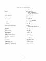
Operator ’s Manual
OjyjEGA
ENGINEERING, INC.
AnO.VfEG.4 Group Company
WARRANTY
OMEGA warrants this unit to be free of defects in materials and workmanship and to give satisfactory service for a period
of 13 months from date of purchase. OMEGA Warranty adds an additional one (1) month grace period to the normal one
(1) year product warranty to cover handling and shipping time. This ensures that our customers receive maximum
coverage on each product. If the unit should malfunction, it must be returned to the factory for evaluation. Our Customer
Service Department will issue an Authorized Return (AR) number immediately upon phone or written request. Upon
examination by OMEGA, if the unit is found to be defective it will be repaired or replaced at no charge. However, this
WARRANTY is VOID if the unit shows evidence of having been tampered with or shows evidence of being damaged as
a result of excessive current, heat, moisture, vibration, or misuse. Components which wear or which are damaged by
misuse are not warranted. These include contact points, fuses, and
triacs.
THERE ARE NO WARRANTIES EXCEPT AS STATED HEREIN. THERE ARE NO OTHER WARRANTIES, EXPRESSED
OR IMPLIED, INCLUDING BUT NOT LIMITED TO THE IMPLIED WARRANTIES OF MERCHANTABILITY AND OF
FITNESS FOR A PARTICULAR PURPOSE. IN NO EVENT SHALL OMEGA ENGINEERING, INC. BE LIABLE FOR
CONSEQUENTIAL, INCIDENTALOR SPECIAL DAMAGES. THE BUYER
’S SOLE REMEDY FOR ANY BREACH OF
THIS AGREEMENT BY OMEGA ENGINEERING, INC. OR ANY BREACH OF ANY WARRANTY BY OMEGA
ENGINEERING, INC. SHALL NOT EXCEED THE PURCHASE PRICE PAID BY THE PURCHASER TO OMEGA
ENGINEERING, INC. FOR THE UNIT OR UNITS OR EQUIPMENT DIRECTLY AFFECTED BY SUCH BREACH.
Return Requests/Inquirie
s
Direct all warranty and repair requests/inquiries to OMEGA Customer Service Department, telephone number
(203) 359-1660. Before returning any instrument, please contact the OMEGA Customer Service Department to obtain
an authorized return (AR) number. The designated AR number should then be marked on the outside of the return
package.
To avoid processing delays, also please be sure to include:
1. Returnee ’s name, address, and phonenumber.
2. Model and Serial numbers.
3. Repair instructions.
One Omega Drive, Box 4047
Stamford, Connecticut 069074047
(203) 359-1660 Telex: 996404 Cable: OMEGA FAX: (203) 359-7700
OMEGA3 is a registered trademark of OMEGA ENGINEERING, INC.
0 Copyright 1986 OMEGA ENGINEERING, INC. All rights reserved including illustrations. Nothing in this manual may
be reproduced in any manner, either wholly or in part for any purpose whatsoever without written permission from
OMEGA ENGINEERING, INC.
Printed in U.S.A.
1
M446/026
TABLE OF CONTENTS
Page No.
PART I - INTRODUCTION
Specification
s
General Descriptio
1
2
n
PART II - INSTALLATION
1.
2.
3.
Unpacking
Mounting
Wiring
PART III - OPERATION INSTRUCTION
TECHNICAL INFORMATION
1.
2.
2
2
3
&
Controls
Operation
4
4/s
PART IV - CALIBRATION
1.
2.
3.
PART
1.
2.
3.
4.
Calibration interval
Equipment required
Calibration procedure
5
5
5/6
V SERVICE
Block diagram
Table I
Transmitter dimensions input/output connections and
Adjustment pot location
Table II
7
8
9
10
MODEL PHTX-11 SPECIFICATIONS
Spans:
Any 1 thru 14,
jumper programmable
zero and span adjustable
Input Impedance:
1 x 10¹³ ohm
Output Current:
4 to
Power Supply:
12 to 80 VDC
2onlA
ii Ez iim+DC>O~~~ONAL
Load Resistor:
0 to 3400 ohms
Linearity:
*.Ol pH
Temperature Coefficient:
f. 02%/OC
(Display and current out)
Accuracy:
ht.01 pH
Repeatability:
k.01 pH
Output meter:
3% digit
Supply Voltage Effect:
.Ol%/Volt
Operating Temperature:
-10 to +60°C
R.H.:
0 to 95%
Isolation:
600 VDC or peak
Common Mode Rej.:
-120dB @ 60 Hz
Temperature Compensation:
Manual or auto
-l-
LC D
PART I - INTRODUCTION
General description
The OMEGAmModel PHTX-11 is a 2-wire
pH/ORP transmitter featuring input-output isolation,
wide power supply range, high input impedance, LCD digital display,
modular construction, programmable span selection,
manual/automatic temperature
compensation and a NEMA
4X housing as a standard enclosure.
The Model PHTX-11 accepts as its input any
pH probe via a BNC co-axial connector.
It transforms the probe signal to a 4 to 20mA D.C.
signal that may be transmitted
over 2-wires to a control location.
The signal wires also provide power to the
transmitter.
The output is monitored by placing a load resistor in the current
loop.
Any D-C. power supply from 12 to 80 volts may be used.
The input is isolated from the output to prevent accidental damage of sensitive data gathering
equipment at the control location.
The pH level is constantly displayed on a 3% digit L.C.D.
allows the display to indicate the
mA output on command.
The
the
can
to
user can change the range of output signal by utilizing jumpers on one of
circuit boards and adjusting the zero and span pots.
The 4 to 20mA output
be for the full 0 to 14
pH range or as little as 1
pH unit, for example 6
7 pH.
PART II
1.
A push button switch
- INSTALLATION
Unpacking
remove shipping ties or clamp.
After unpacking,
remove instrument cover,
Note any special instructions included in the package.
2.
.
Mounting
2.0 Before mounting the signal conditioner enclosure, remove the assembled
circuit boards by removing the two
phillips head screws in the bottom
of the enclosure.
- the unit can be supported by ridged conduit using
2.1 Conduit Mounting
the appropriate size hubs in the ends of the box (ie:
l/2" or 3/4").
Cut the threaded male portion to allow room for the circuit board.
2.2 Flat Surface
- mounting to a flat surface requires the heavy PVC mounting
The surface should be drilled and the
feet be attached to the box.
#lO screws and nuts.
feet mounted with
"U" bolts and nuts.
2.3 Pipe Mounting
- attachment to a round pipe requires
The "U" bolts should bolt to the heavy PVC mounting feet.
-2-
2.4 Panel Mounting
- refer to Table II for hole sizes and locations.
mounting requires the PVC mounting feet and four PVC mounting blocks.
The blocks are drilled and tapped for
#lo-24 screws.
3.
This
Wiring
3. 1
After the enclosure is properly mounted the wires for input, output,
ground and remote temperature sensing should be routed through the enclosure hubs.
These connections should be trimmed to the proper length
and connected to the circuit board assembly.
The circuit board assembly
should then be placed in the enclosure and fastened to the bottom of
the enclosure with the two
phillips head screws supplied.
3. 2
The input probe connector is a BNC jack mounted on the input circuit
board.
Use only a coaxial cable that has isolation around the shield.
The shield is isolated from ground and this isolation should be maintained
for proper operation. For best results,
the probe cable should not be
longer than 10 feet.
Long cables result in slow response because the
probe must charge the cable capacitance through the high probe source
resistance.
3. 3
The output vires are isolated from the input and ground, connections
are made to the terminal strip observing polarity to the terminals marked
These wires are to be connected to a D.C. power supply through
+, - out.
a load resistor.
The wires can be as long as necessary.
3. 4
The Loop resistor can be either in the positive or negative power supply
lead.
The value of the loop resistor depends on the voltage required
at the monitoring location.
Calculate the required power supply voltage
from the following equation:
Minimum power supply voltage
= 12 + c.02
x RL).
A convenient value for the loop resistor might be 250 ohms, resulting in a 1V to 5V output signal using this as an example: RL
= 250
ohms, vo = 1v to 5v.
Minimum supply voltage
= 12 + c.02 x 250) = 17V.
The maximum supply voltage is 80V.
3. 5
If the probe is used, it should be
The temperature probe is optional.
connected to the terminal strip connection marked with the resistor
The probe cable should be shielded and the shield connected to
bol.
the ground terminal.
3. 6
sym-
Manual temperature compensation requires only a resistor at the terminal
Refer to Table I for
strip connection marked with a resistor symbol.
An 8.66K resistor is normally supplied with
the value vs. temperature.
The rethis value is correct for
25'C compensation.
the transmitter,
sistor used should be metal film
*50 ppm/'C or wire wound
f ppm/OC.
-3-
PART III
1.
2.
- OPERATING INSTRUCTIONS
& TECHNICAL INFORMATION
Controls
1.1
Display switch is
1abeled"Press for mA" on the cover.
The display will
indicate 0.00 pH to 14.00 pH when the switch is in the relaxed position.
When the switch is pressed and held,
the display will indicate the output
current to mA, normally 4.0 mA to 20.0 mA.
1.2
"pH CAL" potentiometer is an offset adjustment for the
pH probe on the
input circuit board.
This adjustment allows standardization of different
probes, it affects the displayed readout and the output current.
1.3
"Slope" potentiometer is a gain adjustment on the input circuit board.
This adjustment is used to standardize the readings for probes with less
than 100% efficiency,
it affects the displayed readout and the output
current.
1.4
"R19" potentiometer is a gain adjustment on the output circuit board.
This adjustment is factory set and should not need adjustment in the
field, it affects the displayed
pH readout only.
1.5
"ZERO" potentiometer is an offset adjustment on the output board.
This
adjustment sets the 4
mA output current level for the desired
pH level,
it is used in conjunction with the range switch.
The “Zero" pot affects
the output current only.
There is interaction between the "Zero" and
"Span" pots.
1.6
"SPAN" potentiometer is a gain adjustment on the output board.
This
adjustment sets the 20
mA output current level for the desired
pH level,
it is used in conjunction with the range switch.
The "Span" pot affects
the output current level only.
There is interaction between the "Zero"
and "Span" pots.
1.7
Range jumpers are located on the output board.
These jumpers allow the
user to increase the sensitivity of the output.
There are 4 jumper pairs
of pads, the uppermost position is not used; there are no traces connected
Jumper #l is located in the pair of
pads second
to this pair of pads.
from the top, and this jumper is for full scale output currents of 6
to 14 pH units.
Jumper #2 is located in the third pair of pads, it may
be added to obtain a full scale output of 2 to 6
Jumper #3
pH units.
is added for a full scale output of 1 to 2
pH units.
Operation
2.1 Initialization of the transmitter consists of making the connections
described in the wiring (section
II-31 of this manual and placing the
The display
sensor in a known buffer solution and turning the power on.
pH value of the buffer solution.
should indicate the
2.2 Probe standardization is accomplished by adjusting
"pH CAL" with the
for a reading of 7.0 and the "Slope"
probe in a 7.0 pH buffer solution
4.0 pH or a iO.0 buffer solution.
adjustment.when
the probe is in a
to the user.
The choice of a 4.0 or 10.0 is up
-4-
2.3 Test the display by pressing the display switch.
indicate
PART IV
The display should
mA and the decimal point should shift one place to the right.
- CALIBRATION
The recommended calibration interval for the transmitter is six months under
normal operating conditions,
and assuming the sensor is in good condition.
This system may need adjustment to compensate for reduced efficiency of the
sensor before the calibration interval.
Equipment Required
2.1 pH Simulator or a
millivolt source.
2.2 Precision digital
multimeter.
2.3 D.C. power supply
24 to 30 volts.
2.4 Load resistor 250
ohm or 500 ohm.
Calibration Procedure
3. 1
Connect the equipment as shown in block diagram.
3. 2
the output jumper should be in the full
Before making any adjustments,
range position (Range
#l>. Input adjustments should not be made while
greater than 2OmA).
the-output is in an-over current condition (ie:
Remove the cover from the range switch and turn all switches "Off".
3. 3
"pH CAL" adjustment is made with the input at zero volts from the
Adjust the pot
millivolt source or a
pH of "7" on the pH Simulator.
the display reads 7.00.
Use an 8.66K resistor
for manual temperature compensation at the terminals with the resistor
symbol (25'C compensation).
Refer to Table I for resistance values and
input millivolt values for other temperatures.
3. 4
"14" pH on the
Refer to Table I for the millivolt equivalent if a
pH Simulator.
Ad,just "SloPe" for a reading of 14.00.
millivolt source is used.
3. 5
Output ranging is accomplished with the jumpers described in Section
"SLOPE" adjustment is made with the input at
1.7, they are used in conjunction with the Span and Zero adjustments.
RANGE i/l is with Jumper
#l in place.
The PHTX-11 is shipped with this
The output is adjustable for a span of 6 to 14
pH
jumper in place.
units, for spans of less than 14
pH, the "Zero" adjust sets for the 4
mA point at the lowest
pH point of the range, and the "Span" sets the
The adjustments are
20 mA point at the highest
pH point of the range.
do not attempt large changes, work both adsensitive and interactive,
justments in turn with small changes.
RANGE #2 is with jumpers
fl and 112 in place.
for a span of 2
to 6 pH units.
-5-
The output is adjustable
until
RANGE #3 is with jumpers
al, #2, and #3 in place.
pH units.
for a span of 1 or 2
The output is adjustable
3.6 SPAN h ZERO adjustments interact and require going back and forth between
Connect a millivolt source,
them.
or preferably a
PII simulator
at the input, a resistor at the temperature compensation terminals.
Adjust
(Refer to Table I for the correct resistor and millivolt values).
for 20 mA at the desired
pH levels.
the "Zero" for 4
mA and the "Span"
-6-
----!-!
_ -
<
l
_
__
iI_
i
I ---
‘
-7 -
TABLE
Temp.
O'C
oH
mv.
0
+379.3
2
3
1
5
6
+325
.1
1-270.1
+216
.8
+162
.6
+108
.4
+ 54.19
8
9
10
11
12
13
14
- 54.1 9
-108. 4
-162. 6
-216. 8
-270. 1
-325. 1
-379. 3
I
I
50°C
mv.
7o
c
”
+414-o
+434
.9
+354
.9
+372
.8
+295
.a
+310
.7
‘236. 6
+248
.5
+177
.5
+186
.4
+i18.3
+124
.2
+ 59.15 + 62.13
+448-a
+476
.6
+408
.5
+340
.5
i272. 4
+204
.3
+136
.2
+ 68.0 9
+504
.4
+432
.3
~360
.3
1-288.2
t-216.2
+144
.1
+ 72.0 5
+518.2
+384
.7
+320
.6
+256
.5
+192
.-l
+12a
.
2
+ 64
.12
- 59.15
- 64.1 2
-128. 2
-192. 4
-256. 5
-320. 6
-384. 7
-4-4-8.8
- 68.0 9
-136. 2
-204. 3
-272. 4
-340. 5
-408. 5
-476. 6
- 72.0 5
-144. 1
-216. 2
-288. 2
-360.3 ,
-432. 3
-504. 4
- 74.0 3
-148.1
-222. 1
-296. 1
-370. 2
-444. 2
-518.2
2s
c
”
mv.
4o
c
”
mv.
9o
c
”
100°
C
mv.
mv.
mv.
0
0
Temp.
Comp.
Res.
20.27K
+444
.2
+370
.2
+296
.1
+333
___
.L
+i48.1
+ 74.0 3
-118.3
-177.
-236.
-295.
-354.
-414.
5
6
8
9
0
8.66K
- 62.13
-124. 2
-186. 4
-248. 5
-310. 7
-372. 8
-434.9
5.94K
4.74K
.
-a-
3.08K
1.98K
1.58K
-
b
v-
1
TABLE II
PAN EL CUT-OUT
’
7
.t
DIA.
HOLE
-lO-
FAX 1M31359-Tmo
QWKE%k,. .Your Source for Process
Measurement and Control
TEMPERA7UWE
RTD & Thermistor
Probes &Assemblies
Cl Connector Systems and Panels
Cl Wire: Thermocouple, RTD and Thermistor
Cl Calibrators and Ice Point References
Cl Recorders, Controllers and Process Monitors
Cl Data Acquisition Modules and Data Loggers
Cl Computer Sensor Interface -
Cl Thermocouple,
PRESSURElSTRAlN
Cl Transducers
Cl Strain Gauges
Cl Load Cells
Cl Pressure Gauges
Cl Instrumentation
FLOW
Cl Rotameters
Cl Flowmeter Systems
Cl Air Velocity Indicators
Cl Turbine/Paddlewheel Systems
Cl Vortex Meters and Flow Computers
PM
•!
Electrodes
Cl Benchtopllaboratory Meters
Cl Controllers
Cl Calibrators/Simulators
?? Transmitters
AnO.MEGrl Group Cornpuny
One Omega Drive, Box 4047
Stamford, Connecticut 06907-0047
(203) 359-1660 Telex: 996404 Cable: OMEGA FAX: (203) 359-7700