1
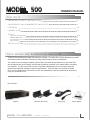
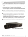
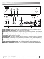
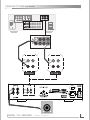
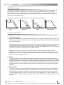
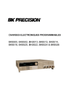
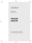
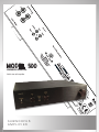
MODEL 500
OWNERS MANUAL
500W class A/B amplifier
SUBWOOFER
AMPLIFIER
I M P O R TA N T SA F ET Y I N S T R U C T I O N S
Read these instructions.
Keep these instructions.
Heed all warnings.
Follow all instructions.
Do not use this apparatus near water.
Clean only with dry cloth.
Do not block any ventilation openings. Install in accordance with the manufacturer’s instructions.
Do not install near any heat sources such as radiators, heat registers, stoves, or other apparatus (inlcuding
amplifiers) that produce heat.
Do not defeat the safety purpose of the polarized or grounding-type plug. A polarized plug has two blades with
one wider than the other. A grounding type plug has two blades and a third grounding prong. The wide blade
or the third prong are provided for your safety. If the provided plug does not fit into your outlet, consult an
electrician for replacement of the obsolete outlet.
Protect the power cord from being walked on or pinched particularly at plugs, convenience receptacles, and the
point where they exit from the apparatus.
Only use attachments/accessories specified by the manufacturer.
Unplug this apparatus during lightning storms or when unused for long periods of time.
Refer all servicing to qualified service personnel. Servicing is required when the apparatus has been damaged
in any way, such as power-supply cord or plug is damaged, liquid has been spilled or objects have fallen into the
apparatus, the apparatus has been exposed to rain or moisture, does not operate normally, or has been dropped.
WARNING: To reduce the risk of fire or electric shock, this apparatus should not be exposed to rain or moisture
and objects filled with liquids, such as vases, should not be placed on this apparatus.
To completely disconnect this equipment from the mains, disconnect the power supply cord plug from the
receptacle.
The mains plug of the power supply cord shall remain readily operable.
WARNING: Disconnect power before making any connection to the speaker terminals as they may present a risk of
electrical shock.
WA R N I N G
CAUTION
The lightning flash with arrowhead
symbol within an equilateral triangle, is intended
to alert the user to the presence of uninsulated
“dangerous voltage “ within the product’s enclosure that may be of sufficient magnitude to
constitute a risk of electric shock to persons.
MODEL 500 AMPLIFIER
OWNER’S MANUAL
!
The exclamation point within an equilateral triangle is intended to alert the user to the
presence of important operating and maintenance
(servicing) instructions in the literature accompanying the product.
MODEL 500
OWNERS MANUAL
CONTENTS
I M P O R T A N T S A F E T Y I N S T R U C T I O N S 2
Y O U R M O D E L 5 0 0 S U B W O O F E R A M P L I F I E R 3
F E A T U R E S 4-5
C O N N E C T I O N 6-7
SETUP
Tips, Hints, & Suggestions MODEL 500 Controls
Fine Tuning the Controls
Other Controls
S P E C I F I C A T I O N S 8-9
9
9
10
1 0 YO U R M O D E L 5 0 0 S U BWO O F E R A M P L I F I E R
Thank you for purchasing the Model 500 subwoofer amplifier. The Model 500 has been developed to provide
extraordinary power and clarity while also providing a broad range of woofer compatibility.
This manual covers operating procedures, general setup, and technical specifications for your Model 500.
We recommend that you thoroughly read through the material contained in this manual before connecting
your amplifier. This will ensure that you have a complete understanding of how to properly setup and
operate your subwoofer amplifier for optimum performance. Thank you again for choosing the Model
500—we are confident that it will provide you with the extraordinary power and performance necessary to
bring your subwoofer to life.
Box Contents:
Amplifier
MODEL 500 AMPLIFIER
Rack Ears with Screws OWNER’S MANUAL
Power Cord
Owners Manual
F E AT U R E S
The MODEL 500 subwoofer amplifier was designed to offer performance, value, and flexibility. It
incorporates a 500W class A/B amplifier utilizing the patented BASH technology for high electrical efficiency.
4 independent controls offer flexibility to integrate nearly all subwoofers with the main speakers and the
listening environment. (Instructions for fine tuning these controls are described in a later section of this
manual.)
The continuously-variable low pass filter network is adjustable from 40Hz to 120Hz and can be bypassed if it
is preferable to use an external filter or one located in an outboard receiver or processor.
The continuously-variable phase circuit is adjustable from 0 to 180 degrees to finely integrate the subwoofer
with the main listening speakers.
The MODEL 500 incorporates a unique continuously-variable subsonic filter that is adjustable from 20Hz to
35Hz that preserves the amplifiers power for only bass frequencies that are reproducible by the subwoofer.
It also helps to protect the subwoofer from being overdriven and can help to reduce distortion by reducing
extreme woofer excursion.
A defeatable Auto-power mode turns the amplifier on automatically when a signal is detected. The Autopower mode can be defeated if it is desirable to use a remote AC circuit to control the amplifier power.
Dual subwoofer outputs allow multiple woofers to be connected to the same amplifier without having to
resort to pigtails, wire nuts, or specialized connectors.
The Model 500 incorporates stereo Line Level inputs and outputs that permit the amplifier to be connected
between a preamplifier and amplifier without the need for Y-connectors. The Line-Level inputs also
incorporate a buffered internal summing network so that a mono signal is derived from the left and right
channels while maintaining the stereo signal integrity for the main stereo speakers.
A double-insulated isolated-ground electrical supply prevents electrical ground loops and reduces the noise
floor of the entire audio system.
Model 500 amplifier shown with rack ears attached.
MODEL 500 AMPLIFIER
OWNER’S MANUAL
F E A T U R E S (continued)
1
2
7
3
4
8
5
9
6
10
11
12
1 Power Mode Switch – Selects if amplifier power is signal activated; Auto=Signal Sensing, On=Bypassed (Amp ON)
2 Power and Standby Mode Indicator – Off=No Power; Blue=On; Red=Standby
3 Phase Control – Adjusts relative alignment of output signal with respect to the input; 0o=In Phase, 180o=Out of Phase
4 Crossover Bypass Switch – Selects if internal crossover (low pass filter) is active, Variable=Active; Bypass=Inactive
5 Crossover Frequency Control – Adjusts low pass filter cutoff frequency
6 Level Control – Adjusts output level to subwoofer
7 Subwoofer Output – Dual sets of 5-way binding posts provide connection for subwoofer(s); Outputs 1 & 2 are parallel
8 Line Level Input – Input connection for RCA Line Level signals from processor or preamp; Includes LFE & Sub signals
9 Line Level Output – Input signal is passed to these jacks to allow multiple connections without the use of Y-cables
10 Subsonic Filter Adjustment – Adjustment to determine lower frequency limit of amplification
11 Power Input Receptacle and Fuse Holder – IEC 2-conductor 120V receptacle accepts supplied IEC power cord
12 Master (Main) Power Switch – Primary power; On=Power Enabled; OFF=Power disconnected from amplifier circuit
MODEL 500 AMPLIFIER
OWNER’S MANUAL
CONNECTION
No signal connection cable is provided with the MODEL 500 amplifier since the length of cable is installation
specific. A shielded RCA type coaxial cable or a shielded two-conductor wire with RCA type connectors is required
for connection of the MODEL 500 to the audio system.
Before making any connections, ensure that power cord is disconnected or that the main power switch is switched
to the off position.
Input Signal: Follow the diagram on page 6 for connecting the subwoofer to your audio system. Use the option
that best suits your installation. The information below will aid in determining which option to use.
OPTION 1 (Left - Right Stereo)
If an LFE (Low Frequency Effect) or Subwoofer output is available then skip to Option 2 since it will likely produce
the best results. If no LFE output is available and a line level Front Channel Output or Preamplifier Output is
available, then this (Option 1) is the preferred method of connection.
Per the Option 1 drawing on the adjacent page, use a stereo RCA style (patch) cable and connect the left and
right line level (RCA style) front channel outputs of your receiver or preamplifier/processor to the Left/Right Line
Level inputs of the MODEL 500.
OPTION 2 (LFE)
If the amplifier is to be connected to a modern home theater receiver or processor with an available LFE or
Subwoofer output then this option will likely produce the best results. If no LFE or Subwoofer output is available
but a line level Front Channel Output or Preamplifier Output is available, then use Option 1.
Per the Option 2 drawing on the adjacent page, use a single RCA style (patch) cable and connect the
line level (RCA style) LFE or Subwoofer output of your receiver or preamplifier/processor to the Left/LFE
Line Level input of the MODEL 500.
AC Power: The unit is shipped with a standard IEC AC cable. Remove this cable from its packaging and insert
the cord into the IEC receptacle on the back of the subwoofer. It is best to connect power only after all other
connections are made. Connect the power cord to an AC wall receptacle or similar source.
MODEL 500 AMPLIFIER
OWNER’S MANUAL
C O N N E C T I O N (continued)
VIDEO
PRE OUT
SINGLE
AUDIO
CENTER
VIDEO
L
S-VIDEO
R
IN
DVD
CD
ANTENNA
DVD
IN
VCR
OUT
VCR
OUT
FRONT A
L
AM
R
FRONT SURROUND.
SPEAKERS
CENTER
SURROUND
L
R
SUR.
BACK
SUB
WOOFER
SURROUND BACK / BI-AMP
L
R
AC OUTLETS
GND
FM
75 Ω
UNBAL
REMOTE
OUT
PRE OUT
SINGLE
CENTER
L
R
FRONT SURROUND.
SUR.
BACK
SUB
WOOFER
Line Level
Line Level
Left/
LFE
Left/
LFE
Right
Right
OPTION 1
OPTION 2
Subwoofer
MODEL 500 AMPLIFIER
OWNER’S MANUAL
SETUP
Tips, Hints, & Suggestions
The MODEL 500 controls will allow you to make the best of virtually any installation. If you feel
uncomfortable with setting up your MODEL 500 after reading through this manual then you should
consider enlisting the help of an experienced person or contacting your dealer.
Below are a few generalized rules for understanding the acoustic nature of low frequency sound
reproduction in an average residential listening room. These rules will aid in understanding the best
placement of your subwoofer and the tuning of your MODEL 500 amplifier. Experiment with the
adjustments of your MODEL 500 to determine what works best in your listening room.
Virtually all rooms have significant resonant modes. The listener will experience these resonant
modes as an acoustic increase or decrease in intensity at certain frequencies. These resonant
modes are a result of reflected acoustic energy within the room interacting with other acoustic
energy, either reflected or direct. These frequency dependent nodes or antinodes, as they
are called, are different for every listening position within the room. Equalization cannot
simultaneously compensate for all locations within a room. Only physical elements within or
at the room’s boundaries can effectively alter the room’s behavior. These resonant modes can
produce large errors in the frequency response and reduce the overall enjoyment of the audio
reproduction. Subwoofer placement has some effect on the location of the resonant modes.
One should contact an expert in the field of acoustics if one finds that the low frequency
reproduction in their room is unsatisfactory.
Placing a subwoofer near a wall will substantially increase its effective radiating power,
especially at very low frequencies. Placing the subwoofer near the intersection of two walls (a
corner) will substantially increase it even more. Corner loading, as it is called, is an excellent
way to get bass extension and greater acoustic output from your subwoofer and can increase
the listening pleasure.
Placing the subwoofer close to the listening/sitting position will increase the intensity of the
transients and reduce the acoustic power demands from the subwoofer. The listener will hear
more direct sound from the subwoofer and less reflected sound.
Bass frequencies are generally considered to be omnidirectional and tend to have no
localization. That is to say that it is difficult to determine their place of origin. For this reason,
placement of most subwoofers is not limited to the front of the room. However, in practice
this is not the case. There are cues such as tactile vibration and higher frequency signal
components that can suggest the direction of the source. For this reason it may be desirable
to locate the subwoofer at the front of the room near the main speakers. It may also be
necessary to reduce the crossover frequency if one finds that the bass sounds too detached
from the other sound sources.
If placement of the woofer at the front of the room is not an option, consider placing the
subwoofer at the back of the room. Placement directly behind the listening position can
produce very good results as well as corner loading in the back of the room.
Using multiple woofers at opposite corners of the room can be done to balance the localization
of the sound.
It is not necessary to direct the front of a subwoofer at the listening position.
MODEL 500 AMPLIFIER
OWNER’S MANUAL
S E T U P (continued)
MODEL 500 Controls
The MODEL 500 subwoofer amplifier has four variable controls to integrate its output to the subwoofer and
for tailoring the subwoofer’s output to the room and to the primary speakers (also known as satellites).
These controls are Level, Crossover Frequency, Phase, and subsonic filter. The control with the most audible
effect is the Level control, followed by the Crossover Frequency, Phase control, and then Subsonic filter,
which has the least audible effect.
The following legend shows graphically how each control affects the audio signal.
SPL
(dB)
Frequency (Hz)
SPL
(dB)
SPL
(dB)
Frequency (Hz)
Level
Frequency (Hz)
Frequency
SPL
(dB)
Phase (Degrees)
Phase
SPL
(dB)
20
35
Frequency (Hz)
Subsonic Filter
Fine Tuning the Controls
We recommend the following method as a starting point for fine tuning the MODEL 500 subwoofer amplifier.
A) Level and Frequency
Begin with the amplifier’s Level control all the way down and the Frequency adjustment set to 120Hz. With
the Frequency control in this position the woofer will output higher frequencies that will likely be duplicated
by the satellite speakers.
Play some familiar music through the system (music with robust bass content) and increase the Level control
until the bass passages sound robust or exaggerated. Then reduce the Frequency control to blend the
subwoofer with your main system speakers. We have found that most speakers with 6” to 8” woofers blend
well with the crossover set somewhere between 50Hz and 80Hz.
Readjust the Level and the Frequency controls (up or down) as necessary until the bass sounds full,
extended, and natural. Use multiple musical pieces to test the system while fine tuning the controls. If it
sounds like your subwoofer is always producing the same bass note with different recordings it is possible
that the bass level is adjusted too high.
B) Phase
To adjust the Phase, use music with sustained bass notes. Rotate the Phase control back and forth across
its range and listen for the localization of the bass to become more distinct and also slightly louder. While
making this adjustment it can be helpful to temporarily adjust the Frequency control to 120Hz. This should
provide some overlap of the satellite and subwoofer frequencies and help the ears (brain) to distinguish the
two sound sources. Return the Frequency control back to its desired position after performing the phase
adjustment.
C) Subsonic Filter
This control is used to protect the subwoofer from damage due to excessive excursion, reduce distortion,
and also to preserve the amplifiers power in installations where the subwoofer is incapable of reproducing
extremely deep bass passages. Ideally, the control should be set at or just below the system resonance.
The factory default position is 35Hz. This will work well for most subwoofers 12” or less in diameter. For
large subwoofers or where the system resonance is very low the control should be lowered below the 35 Hz
position.
MODEL 500 AMPLIFIER
OWNER’S MANUAL
S E T U P (continued)
Other Controls
A) Crossover Switch
If you choose to bypass the internal crossover and use an external crossover, such as those located in most
modern receivers and processors, then you will need to fine tune the system based on the adjustments
provided by the manufacturer of your electronics in conjunction with the Level and Phase controls on the
MODEL 500. Note, the Level and Phase adjustments on the MODEL 500 are not bypassed and will still
function as indicated above.
To bypass the internal crossover, move the Crossover switch (6) to the Bypass position. The subwoofer will
now pass signals up to 300Hz.
B) Auto Power Mode Switch
The same circuit also places the MODEL 500 into standby mode when no signal has been detected for a
period of approximately 10 minutes. This signal sensing circuit can be bypassed by switching the Auto switch
(2) to the OFF position if it is preferable to control the MODEL 500’s power with a remotely operated power
source
S P E C I F I C AT I O N S
Frequency Response: Crossover Frequency:
Phase Adjustment:
Amplifier Output Power:
Distortion: Audio Inputs:
Input Impedance:
Input Power: Input Power Connection:
Power (Mains) Fuse:
Power Modes:
Auto Off Delay:
Dimensions: Weight:
Shipping Dimensions:
Shipping Weight:
MODEL 500 AMPLIFIER
20Hz – 300Hz
40Hz – 120Hz (Low-pass filter with bypass switch)
0 – 180 degrees (Continuously variable)
500 watts RMS into 4 ohms, with thermal and clipping limiters
250 watts RMS into 8 ohms, with thermal and clipping limiters
Less than 0.2% at rated power
Summing stereo line level (RCA x2)
LFE (RCA shared with Left input connector)
Line Level – 20kohms, Unbalanced
120V 60Hz AC
IEC 2-wire receptacle with integral fuse holder
5A 250V GMA style Fast Blow
Auto signal sensing and always on
~10 minutes
16-7/8"W x 3-7/8"H x 14.75"D, (429W x 98H x 375D)mm (with feet, without ears)
15lbs (6.8kg)
21.5"W x 8.5"H x 17.5"D, (550W x 220H x 450D)mm
20lbs (9.1kg)
OWNER’S MANUAL
10
NOTES
MODEL 500 AMPLIFIER
OWNER’S MANUAL
11
OEM SYSTEMS COMPANY
Sparks, Nevada (775) 355-0405
(800) 291-0561 FAX
www.oemsystems.com
[email protected]
Rev. D