1
Part No. 204515-C
April 2000
4401 Great America Parkway
Santa Clara, CA 95054
Using the Passport 8100 Modules
Copyright © 2000 Nortel Networks
All rights reserved. April 2000.
The information in this document is subject to change without notice. The statements, configurations, technical data,
and recommendations in this document are believed to be accurate and reliable, but are presented without express or
implied warranty. Users must take full responsibility for their applications of any products specified in this document.
The information in this document is proprietary to Nortel Networks NA Inc.
Trademarks
NORTEL NETWORKS, BayStack, and Passport are trademarks of Nortel Networks.
All other trademarks and registered trademarks are the property of their respective owners.
Statement of Conditions
In the interest of improving internal design, operational function, and/or reliability, Nortel Networks NA Inc. reserves
the right to make changes to the products described in this document without notice.
Nortel Networks NA Inc. does not assume any liability that may occur due to the use or application of the product(s)
or circuit layout(s) described herein.
USA Requirements Only
Federal Communications Commission (FCC) Compliance Notice: Radio Frequency Notice
Note: This equipment has been tested and found to comply with the limits for a Class A digital device, pursuant to
Part 15 of the FCC rules. These limits are designed to provide reasonable protection against harmful interference
when the equipment is operated in a commercial environment. This equipment generates, uses, and can radiate radio
frequency energy. If it is not installed and used in accordance with the instruction manual, it may cause harmful
interference to radio communications. Operation of this equipment in a residential area is likely to cause harmful
interference, in which case users will be required to take whatever measures may be necessary to correct the
interference at their own expense.
European Requirements Only
EN 55 022 Statement
This is to certify that the Nortel Networks Passport 8100 Modules are shielded against the generation of radio
interference in accordance with the application of Council Directive 89/336/EEC, Article 4a. Conformity is declared
by the application of EN 55 022 Class A (CISPR 22).
Warning: This is a Class A product. In a domestic environment, this product may cause radio interference, in which
case, the user may be required to take appropriate measures.
Achtung: Dieses ist ein Gerät der Funkstörgrenzwertklasse A. In Wohnbereichen können bei Betrieb dieses
Gerätes Rundfunkstörungen auftreten, in welchen Fällen der Benutzer für entsprechende Gegenmaßnahmen
verantwortlich ist.
Attention: Ceci est un produit de Classe A. Dans un environnement domestique, ce produit risque de créer des
interférences radioélectriques, il appartiendra alors à l’utilisateur de prendre les mesures spécifiques appropriées.
EC Declaration of Conformity
These products conform to the provisions of Council Directive 89/336/EEC and 73/23/EEC. The Declaration of
Conformity is available on the Nortel Networks World Wide Web site at http://libra2.corpwest.baynetworks.com/
cgi-bin/ndCGI.exe/DocView/.
ii
204515-C
Japan/Nippon Requirements Only
Voluntary Control Council for Interference (VCCI) Statement
Taiwan Requirements
Bureau of Standards, Metrology and Inspection (BSMI) Statement
Canada Requirements Only
Canadian Department of Communications Radio Interference Regulations
This digital apparatus (Passport 8100 Modules) do not exceed the Class A limits for radio-noise emissions from
digital apparatus as set out in the Radio Interference Regulations of the Canadian Department of Communications.
Règlement sur le brouillage radioélectrique du ministère des Communications
Cet appareil numérique (Passport 8100 Modules) respecte les limites de bruits radioélectriques visant les appareils
numériques de classe A prescrites dans le Règlement sur le brouillage radioélectrique du ministère des
Communications du Canada.
Nortel Networks NA Inc. Software License Agreement
NOTICE: Please carefully read this license agreement before copying or using the accompanying software or
installing the hardware unit with pre-enabled software (each of which is referred to as “Software” in this Agreement).
BY COPYING OR USING THE SOFTWARE, YOU ACCEPT ALL OF THE TERMS AND CONDITIONS OF
THIS LICENSE AGREEMENT. THE TERMS EXPRESSED IN THIS AGREEMENT ARE THE ONLY TERMS
UNDER WHICH NORTEL NETWORKS WILL PERMIT YOU TO USE THE SOFTWARE. If you do not accept
these terms and conditions, return the product, unused and in the original shipping container, within 30 days of
purchase to obtain a credit for the full purchase price.
1. License Grant. Nortel Networks NA Inc. (“Nortel Networks”) grants the end user of the Software (“Licensee”) a
personal, nonexclusive, nontransferable license: a) to use the Software either on a single computer or, if applicable, on
a single authorized device identified by host ID, for which it was originally acquired; b) to copy the Software solely
for backup purposes in support of authorized use of the Software; and c) to use and copy the associated user manual
solely in support of authorized use of the Software by Licensee. This license applies to the Software only and does not
extend to Nortel Networks Agent software or other Nortel Networks software products. Nortel Networks Agent
software or other Nortel Networks software products are licensed for use under the terms of the applicable Nortel
Networks NA Inc. Software License Agreement that accompanies such software and upon payment by the end user of
the applicable license fees for such software.
204515-C
iii
2. Restrictions on use; reservation of rights. The Software and user manuals are protected under copyright laws.
Nortel Networks and/or its licensors retain all title and ownership in both the Software and user manuals, including
any revisions made by Nortel Networks or its licensors. The copyright notice must be reproduced and included with
any copy of any portion of the Software or user manuals. Licensee may not modify, translate, decompile, disassemble,
use for any competitive analysis, reverse engineer, distribute, or create derivative works from the Software or user
manuals or any copy, in whole or in part. Except as expressly provided in this Agreement, Licensee may not copy or
transfer the Software or user manuals, in whole or in part. The Software and user manuals embody Nortel Networks’
and its licensors’ confidential and proprietary intellectual property. Licensee shall not sublicense, assign, or otherwise
disclose to any third party the Software, or any information about the operation, design, performance, or
implementation of the Software and user manuals that is confidential to Nortel Networks and its licensors; however,
Licensee may grant permission to its consultants, subcontractors, and agents to use the Software at Licensee’s facility,
provided they have agreed to use the Software only in accordance with the terms of this license.
3. Limited warranty. Nortel Networks warrants each item of Software, as delivered by Nortel Networks and properly
installed and operated on Nortel Networks hardware or other equipment it is originally licensed for, to function
substantially as described in its accompanying user manual during its warranty period, which begins on the date
Software is first shipped to Licensee. If any item of Software fails to so function during its warranty period, as the sole
remedy Nortel Networks will at its discretion provide a suitable fix, patch, or workaround for the problem that may be
included in a future Software release. Nortel Networks further warrants to Licensee that the media on which the
Software is provided will be free from defects in materials and workmanship under normal use for a period of 90 days
from the date Software is first shipped to Licensee. Nortel Networks will replace defective media at no charge if it is
returned to Nortel Networks during the warranty period along with proof of the date of shipment. This warranty does
not apply if the media has been damaged as a result of accident, misuse, or abuse. The Licensee assumes all
responsibility for selection of the Software to achieve Licensee’s intended results and for the installation, use, and
results obtained from the Software. Nortel Networks does not warrant a) that the functions contained in the software
will meet the Licensee’s requirements, b) that the Software will operate in the hardware or software combinations that
the Licensee may select, c) that the operation of the Software will be uninterrupted or error free, or d) that all defects
in the operation of the Software will be corrected. Nortel Networks is not obligated to remedy any Software defect
that cannot be reproduced with the latest Software release. These warranties do not apply to the Software if it has been
(i) altered, except by Nortel Networks or in accordance with its instructions; (ii) used in conjunction with another
vendor’s product, resulting in the defect; or (iii) damaged by improper environment, abuse, misuse, accident, or
negligence. THE FOREGOING WARRANTIES AND LIMITATIONS ARE EXCLUSIVE REMEDIES AND ARE
IN LIEU OF ALL OTHER WARRANTIES EXPRESS OR IMPLIED, INCLUDING WITHOUT LIMITATION
ANY WARRANTY OF MERCHANTABILITY OR FITNESS FOR A PARTICULAR PURPOSE. Licensee is
responsible for the security of its own data and information and for maintaining adequate procedures apart from the
Software to reconstruct lost or altered files, data, or programs.
4. Limitation of liability. IN NO EVENT WILL NORTEL NETWORKS OR ITS LICENSORS BE LIABLE FOR
ANY COST OF SUBSTITUTE PROCUREMENT; SPECIAL, INDIRECT, INCIDENTAL, OR CONSEQUENTIAL
DAMAGES; OR ANY DAMAGES RESULTING FROM INACCURATE OR LOST DATA OR LOSS OF USE OR
PROFITS ARISING OUT OF OR IN CONNECTION WITH THE PERFORMANCE OF THE SOFTWARE, EVEN
IF NORTEL NETWORKS HAS BEEN ADVISED OF THE POSSIBILITY OF SUCH DAMAGES. IN NO EVENT
SHALL THE LIABILITY OF NORTEL NETWORKS RELATING TO THE SOFTWARE OR THIS AGREEMENT
EXCEED THE PRICE PAID TO NORTEL NETWORKS FOR THE SOFTWARE LICENSE.
5. Government Licensees. This provision applies to all Software and documentation acquired directly or indirectly
by or on behalf of the United States Government. The Software and documentation are commercial products, licensed
on the open market at market prices, and were developed entirely at private expense and without the use of any U.S.
Government funds. The license to the U.S. Government is granted only with restricted rights, and use, duplication, or
disclosure by the U.S. Government is subject to the restrictions set forth in subparagraph (c)(1) of the Commercial
Computer Software––Restricted Rights clause of FAR 52.227-19 and the limitations set out in this license for civilian
agencies, and subparagraph (c)(1)(ii) of the Rights in Technical Data and Computer Software clause of DFARS
252.227-7013, for agencies of the Department of Defense or their successors, whichever is applicable.
6. Use of Software in the European Community. This provision applies to all Software acquired for use within the
European Community. If Licensee uses the Software within a country in the European Community, the Software
iv
204515-C
Directive enacted by the Council of European Communities Directive dated 14 May, 1991, will apply to the
examination of the Software to facilitate interoperability. Licensee agrees to notify Nortel Networks of any such
intended examination of the Software and may procure support and assistance from Nortel Networks.
7. Term and termination. This license is effective until terminated; however, all of the restrictions with respect to
Nortel Networks’ copyright in the Software and user manuals will cease being effective at the date of expiration of the
Nortel Networks copyright; those restrictions relating to use and disclosure of Nortel Networks’ confidential
information shall continue in effect. Licensee may terminate this license at any time. The license will automatically
terminate if Licensee fails to comply with any of the terms and conditions of the license. Upon termination for any
reason, Licensee will immediately destroy or return to Nortel Networks the Software, user manuals, and all copies.
Nortel Networks is not liable to Licensee for damages in any form solely by reason of the termination of this license.
8. Export and Re-export. Licensee agrees not to export, directly or indirectly, the Software or related technical data
or information without first obtaining any required export licenses or other governmental approvals. Without limiting
the foregoing, Licensee, on behalf of itself and its subsidiaries and affiliates, agrees that it will not, without first
obtaining all export licenses and approvals required by the U.S. Government: (i) export, re-export, transfer, or divert
any such Software or technical data, or any direct product thereof, to any country to which such exports or re-exports
are restricted or embargoed under United States export control laws and regulations, or to any national or resident of
such restricted or embargoed countries; or (ii) provide the Software or related technical data or information to any
military end user or for any military end use, including the design, development, or production of any chemical,
nuclear, or biological weapons.
9. General. If any provision of this Agreement is held to be invalid or unenforceable by a court of competent
jurisdiction, the remainder of the provisions of this Agreement shall remain in full force and effect. This Agreement
will be governed by the laws of the state of California.
Should you have any questions concerning this Agreement, contact Nortel Networks, 4401 Great America Parkway,
P.O. Box 58185, Santa Clara, California 95054-8185.
LICENSEE ACKNOWLEDGES THAT LICENSEE HAS READ THIS AGREEMENT, UNDERSTANDS IT, AND
AGREES TO BE BOUND BY ITS TERMS AND CONDITIONS. LICENSEE FURTHER AGREES THAT THIS
AGREEMENT IS THE ENTIRE AND EXCLUSIVE AGREEMENT BETWEEN NORTEL NETWORKS AND
LICENSEE, WHICH SUPERSEDES ALL PRIOR ORAL AND WRITTEN AGREEMENTS AND
COMMUNICATIONS BETWEEN THE PARTIES PERTAINING TO THE SUBJECT MATTER OF THIS
AGREEMENT. NO DIFFERENT OR ADDITIONAL TERMS WILL BE ENFORCEABLE AGAINST NORTEL
NETWORKS UNLESS NORTEL NETWORKS GIVES ITS EXPRESS WRITTEN CONSENT, INCLUDING AN
EXPRESS WAIVER OF THE TERMS OF THIS AGREEMENT.
204515-C
v
vi
204515-C
Contents
Preface
Before You Begin ............................................................................................................. xv
Text Conventions .............................................................................................................xvi
Related Publications .......................................................................................................xvii
How to Get Help ..............................................................................................................xix
Chapter 1
About the Passport 8100 Modules
Features .........................................................................................................................1-2
Passport 8190SM Management Module ........................................................................1-4
Ethernet Management Port ......................................................................................1-5
DTE/DCE Switch ......................................................................................................1-6
Serial Ports ...............................................................................................................1-6
Reset Button ............................................................................................................1-6
PCMCIA Card Slot ...................................................................................................1-6
LEDs ........................................................................................................................1-7
Passport 8132TX 32-Port I/O Module ............................................................................1-8
10BASE-T/100BASE-TX Port Connectors ...............................................................1-8
MDA Slot ..................................................................................................................1-9
Comm Port ...............................................................................................................1-9
LEDs ......................................................................................................................1-10
Passport 8148TX 48-Port I/O Module .......................................................................... 1-11
LEDs ......................................................................................................................1-12
Passport 8108GBIC 8-Port I/O Module ........................................................................1-12
LEDs ......................................................................................................................1-13
Redundancy Features ..................................................................................................1-13
Redundant Passport 8190SM Modules .................................................................1-14
Redundant Power Supplies ....................................................................................1-14
Combining Passport 8100 and Passport 8600 Modules ..............................................1-16
204515-C
vii
Chapter 2
Installing a Passport 8100 Module
Chassis Configuration Requirements .............................................................................2-2
Safety and Environmental Precautions ..........................................................................2-2
Installing a Module ..........................................................................................................2-3
Turning On the Chassis Power .......................................................................................2-5
Connecting Cables .........................................................................................................2-6
Replacing Modules .........................................................................................................2-7
Chapter 3
Basic Switch Configuration
Specifying Port Numbers ................................................................................................3-2
Booting the Switch ..........................................................................................................3-3
Logging On to the System ..............................................................................................3-4
Assigning an IP Address to the Management Port .........................................................3-5
Setting System Identification ..........................................................................................3-5
Setting System Security .................................................................................................3-6
Switch Configuration .......................................................................................................3-8
Chapter 4
Troubleshooting
Normal Power-Up Sequence ..........................................................................................4-1
Failure to Get a Login Prompt from the Console Port ....................................................4-2
Failure of Management Software to Recognize I/O Modules .........................................4-2
LED Indications of Problems ..........................................................................................4-2
Port Connection Problems ..............................................................................................4-4
Cabling .....................................................................................................................4-4
Autonegotiation Modes ............................................................................................4-5
Port Interface ............................................................................................................4-6
Installation-Related Issues .............................................................................................4-7
Addresses ................................................................................................................4-7
viii
204515-C
Appendix A
Technical Specifications
General Specifications ................................................................................................... A-1
Passport 8190SM Switch Management Module ............................................................ A-3
Management Port .................................................................................................... A-4
Console Serial Port ................................................................................................. A-4
Modem Serial Port .................................................................................................. A-5
Passport 8132TX Module .............................................................................................. A-6
Data Port Connectors .............................................................................................. A-6
Comm Port Connector ............................................................................................ A-7
MDAs ...................................................................................................................... A-7
Passport 8148TX Module .............................................................................................. A-8
Port Connectors ...................................................................................................... A-8
Passport 8108GBIC Module .......................................................................................... A-9
GBICs ...................................................................................................................... A-9
1000BASE-SX GBIC ...................................................................................... A-10
1000BASE-LX GBIC ....................................................................................... A-10
1000BASE-XD GBIC .......................................................................................A-11
1000BASE-ZX GBIC .......................................................................................A-11
MDI and MDI-X Connections ....................................................................................... A-12
Declaration of Conformity ............................................................................................ A-13
Appendix B
LEDs
Passport 8190SM Switch Management Module ............................................................ B-1
Passport 8132TX and 8148TX I/O Modules .................................................................. B-3
Passport 8108GBIC Module .......................................................................................... B-4
204515-C
ix
Appendix C
Media Dependent Adapters
450 Series MDAs ........................................................................................................... C-2
8100-4TX MDA .............................................................................................................. C-4
8100 Series Fiber MDAs ............................................................................................... C-5
Installing an MDA .......................................................................................................... C-7
Appendix D
Installing GBICs
Installing a GBIC ............................................................................................................ D-2
Appendix E
RFCs and Standards
Index
x
204515-C
Figures
Figure 1-1.
Passport 8190SM Switch Management Module ......................................1-4
Figure 1-2.
LEDs on the Passport 8190SM Module ...................................................1-7
Figure 1-3.
Passport 8132TX Edge Switch Module ...................................................1-8
Figure 1-4.
LEDs on the Passport 8132TX Module ..................................................1-10
Figure 1-5.
Passport 8148TX Edge Switch Module ................................................. 1-11
Figure 1-6.
LEDs on the Passport 8148TX Module ..................................................1-12
Figure 1-7.
Passport 8108GBIC Module ..................................................................1-13
Figure 1-8.
LEDs on the Passport 8108GB Module .................................................1-13
Figure 2-1.
Removing a Filler Panel ...........................................................................2-3
Figure 2-2.
Inserter/Extractor Levers in Extended Position ........................................2-3
Figure 2-3.
Inserting a Module ...................................................................................2-4
Figure 2-4.
Seating the Backplane Connectors ..........................................................2-4
Figure 2-5.
Securing the Module in the Chassis ........................................................2-5
Figure 2-6.
Routing Network Cables ..........................................................................2-7
Figure 3-1.
Port Numbers on High-Density Modules ..................................................3-2
Figure 4-1.
DCE/DTE Switch on the Passport 8190SM Module ................................4-2
Figure A-1.
MDI-X to MDI Cable Connections ......................................................... A-12
Figure A-2.
MDI-X to MDI-X Cable Connections ..................................................... A-13
Figure B-1.
LEDs on the Passport 8190SM Module .................................................. B-1
Figure B-2.
LEDs on the Passport 8132TX and 8148TX Modules ............................ B-3
Figure B-3.
LEDs on the Passport 8108GBIC Module .............................................. B-5
204515-C
xi
xii
Figure C-1.
1000BASE-SX (Shortwave Gigabit) MDA Front Panels ......................... C-2
Figure C-2.
1000BASE-LX (Longwave Gigabit) MDA Front Panels .......................... C-3
Figure C-3.
8100-4TX MDA Front Panel .................................................................... C-4
Figure C-4.
8100 Series MDA Front Panels .............................................................. C-6
Figure C-5.
Installing an MDA .................................................................................... C-7
Figure D-1.
Types of GBICs ....................................................................................... D-1
Figure D-2.
Installing a GBIC ..................................................................................... D-2
Figure D-3.
Removing a GBIC ................................................................................... D-3
204515-C
Tables
Table 1-1.
Power Supply Hot-Swapping ................................................................1-15
Table 2-1.
Connectors and Cables for Passport 8000 Series
Edge Switch Modules .........................................................................2-6
Table 3-1.
Access Levels and Default Login Values ................................................3-4
Table 4-1.
LED Indications of Problems ...................................................................4-3
Table A-1.
Pin Assignments in the Passport 8190SM Management Port ................ A-4
Table A-2.
Pin Assignments in the Passport 8190SM Console Port ........................ A-5
Table A-3.
DTE-to-DCE Pin Assignments ............................................................... A-5
Table A-4.
Passport 8132TX Port Pinouts ................................................................ A-6
Table A-5.
Passport 8148TX Port Pinouts ................................................................ A-8
Table B-1.
LED Operation on the Passport 8190SM Module .................................. B-2
Table B-2.
Module LEDs on the Passport 8132TX and 8148TX Modules ............... B-4
Table B-3.
Port LEDs on the Passport 8132TX and 8148TX Modules ..................... B-4
Table B-4.
Module LEDs on the Passport 8108GBIC Module ................................. B-5
Table B-5.
Port LEDs on the Passport 8108GBIC Module ...................................... B-5
Table C-1.
1000BASE-SX MDA LEDs ..................................................................... C-3
Table C-2.
1000BASE-LX MDA LEDs ..................................................................... C-4
Table C-3.
8100-4TX MDA LEDs ............................................................................ C-5
Table C-4.
8100 Series MDA LEDs ......................................................................... C-6
204515-C
xiii
xiv
204515-C
Preface
Passport™ 8100 modules installed in an Passport 8000 Series chassis create an
edge switch entity within the chassis. These high-performance, low-cost Ethernet
switches from Nortel Networks™ provide a high-density layer 2 switching system
that is ideal for wiring closet applications.
This guide provides information about the features and capabilities of the Passport
8100 modules, including module specifications and switch startup procedures.
This guide discusses the Passport 8190SM, Passport 8132TX, Passport 8148TX,
and Passport 8108GBIC modules. They are referred to collectively as the Passport
8100 modules. Each module is referred to specifically when features and
functions are unique to that particular model.
Before You Begin
This guide is intended for network administrators with the following background:
204515-C
•
Working knowledge of various Ethernet types, including 10BASE-T,
100BASE-TX, 100BASE-FX, and 1000BASE-SX
•
Working knowledge of cable types, including Category 5 unshielded twisted
pair (UTP) and multimode and single-mode optical fiber
xv
Using the Passport 8100 Modules
Text Conventions
This guide uses the following text conventions:
angle brackets (< >)
Indicate that you choose the text to enter based on the
description inside the brackets. Do not type the brackets
when entering the command.
Example: If the command syntax is:
ping <ip_address>, you enter:
ping 192.32.10.12
braces ({})
Indicate required elements in syntax descriptions where
there is more than one option. You must choose only one
of the options. Do not type the braces when entering the
command.
Example: If the command syntax is:
show ip {alerts | routes}, you must enter either:
show ip alerts or show ip routes, but not both.
brackets ([ ])
Indicate optional elements in syntax descriptions. Do not
type the brackets when entering the command.
Example: If the command syntax is:
show ip interfaces [-alerts], you can enter either:
show ip interfaces or show ip interfaces -alerts.
italic text
Indicates file and directory names, new terms, book titles,
and variables in command syntax descriptions. Where a
variable is two or more words, the words are connected
by an underscore.
Example: If the command syntax is:
show at <valid_route> then valid_route
is one variable and you substitute one value for it.
screen text
Indicates command names and options, text that you need
to enter, and system output such as prompts and system
messages.
Example: Set Trap Monitor Filters
xvi
204515-C
Preface
separator ( > )
Shows menu paths.
Example: Protocols > IP identifies the IP option on the
Protocols menu.
vertical line ( | )
Separates choices for command keywords and
arguments. Enter only one of the choices. Do not type the
vertical line when entering the command.
Example: If the command syntax is:
show ip {alerts | routes}, you enter either:
show ip alerts or show ip routes, but not both.
Related Publications
For more information about using the Passport management software or other
Passport 8000 series equipment, refer to the following publications:
•
Getting Started with the Passport 8100 Management Software
(part number 207311-C)
Provides instructions to install management software and describes general
use of the management software.
•
Reference for the Passport 8000 Series Management Software Switching
Operations (part number 207414-C)
Describes how to use Device Manager software to configure and manage
layer 2 (switching) functions, including procedures and illustrations of the
software user interface.
•
Reference for the Passport 8000 Series Command Line Interface Switching
Operations (part number 207308-C)
Describes the command line interface (CLI) commands and parameters. Most
configuration tasks that can be performed using the management software can
also be done using the command line interface.
•
Networking Concepts for the Passport 8000 Series Switch
(part number 207307-C)
Provides general information and description of how a Passport routing
switch handles various networking features, such as VLANs and Multi-Link
Trunking.
204515-C
xvii
Using the Passport 8100 Modules
•
Installing the Passport 8010 Chassis (part number 204518-B)
Describes installation procedures for the Passport 8010 chassis.
•
Installing the Passport 8006 Chassis (part number 207313-B)
Describes installation procedures for the Passport 8006 chassis.
•
Installing the Passport 8001PS AC Power Supply (part number 204519-B)
Describes installation and connection procedures for the Passport 8001PS AC
power supply.
•
Installing the Passport 8002PS DC Power Supply (part number 207314-B)
Describes installation and connection procedures for the Passport 8002PS DC
power supply.
You can print selected technical manuals and release notes free, directly from the
Internet. Go to the support.baynetworks.com/library/tpubs/ Web address. Find the
product for which you need documentation. Then locate the specific category and
model or version for your hardware or software product. Use Adobe Acrobat
Reader to open the manuals and release notes, search for the sections you need,
and print them on most standard printers. Go to the Adobe Systems Web address
at www.adobe.com to download a free copy of Acrobat Reader.
You can purchase selected documentation sets, CDs, and technical publications
though the Internet at the www1.fatbrain.com/documentation/nortel/ Web address.
xviii
204515-C
Preface
How to Get Help
If you purchased a service contract for your Nortel Networks product from a
distributor or authorized reseller, contact the technical support staff for that
distributor or reseller for assistance.
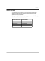
If you purchased a Nortel Networks service program, contact one of the following
Nortel Networks Technical Solutions Centers:
204515-C
Technical Solutions Center
Telephone Number
Billerica, MA
800-2LANWAN (800-252-6926)
Santa Clara, CA
800-2LANWAN (800-252-6926)
Valbonne, France
33-4-92-96-69-68
Sydney, Australia
61-2-9927-8800
Tokyo, Japan
81-3-5740-1700
xix
Chapter 1
About the Passport 8100 Modules
The Passport 8100 modules provide a full complement of switching capabilities in
a Passport 8000 Series chassis. The Passport 8100 modules provide 10/100
megabit per second (Mb/s) autonegotiating twisted pair Ethernet ports, 100 Mb/s
fiber Ethernet ports, and fiber Gigabit Ethernet ports. A Passport 8000 Series
chassis with installed Passport 8100 modules constitutes a single switching entity
with distributed management and full redundancy.
The Passport 8100 modules include a switch management module and
input/output (I/O) modules. For CPU system redundancy, you can install two
management modules. The I/O modules support different types of Ethernet
interfaces with different speeds, port counts, and media types.
The following Passport 8100 modules are available:
•
Passport 8190SM Switch Management Module—management module for the
chassis (page 1-4)
•
Passport 8132TX Edge Switch Module—32-port 10/100 Mb/s Ethernet I/O
module, with expansion slot for optional MDA (page 1-8)
•
Passport 8148TX Edge Switch Module—48-port 10/100 Mb/s Ethernet I/O
module (page 1-11)
•
Passport 8108GBIC Edge Switch Module—1000 Mb/s Ethernet I/O module
with eight bays for installing gigabit interface converters (GBICs) (page 1-12)
An expansion slot on the Passport 8132TX module allows installation of a media
dependent adapter (MDA) to provide other port types. The MDAs support
high-speed connections to servers, shared Fast Ethernet hubs, or backbone
devices.
204515-C
1-1
Using the Passport 8100 Modules
This chapter includes the following information:
•
Summary of features
•
Detailed descriptions of each module
Features
The Passport 8100 modules have the following features:
•
One active and one optional standby CPU subsystem with fast fail-over in the
event of loss of one CPU
•
Hardware redundancy features, including power supplies, chassis fans, and
switch management modules
•
High-speed forwarding rate, up to 3 million packets per second (peak)
•
Store-and-forward switching, providing full-performance forwarding at full
line speed
•
Learning rate of 3 million addresses per second (peak)
•
Address database capacity of up to 16,000 entries at line rate (32,000 entries
without flooding)
•
Connection to a high-speed backplane for forwarding of packets between
modules
•
Front-panel LEDs for monitoring port activity and module operation
•
Expansion slot for installation of an optional media dependent adapter to
provide 100BASE-FX fiber connections, Gigabit Ethernet connections, or
additional 10/100BASE-TX connections (Passport 8132TX module only)
•
Support for Spanning Tree Protocol with one spanning tree group in two
modes:
— IEEE 802.1D-compliant mode
— FastStart mode, which allows the port to reach forwarding state faster
Spanning tree can be disabled on individual ports or the entire switch.
1-2
204515-C
About the Passport 8100 Modules
•
IEEE 802.1Q port-based virtual LANs (VLANs)
•
IEEE 802.1p prioritization
•
IEEE 802.3u-compliant autonegotiating ports, with four modes:
— 10BASE-T half-duplex
— 10BASE-T full-duplex
— 100BASE-TX half-duplex
— 100BASE-TX full-duplex
•
Two hardware-based priority queues per port
•
Multi-Link Trunking (MLT) with up to 4 ports in a trunk and up to 6 MLT
groups in a switch with a single trunk able to span multiple I/O modules,
supporting switch-to-switch trunks and switch-to-server trunks
•
Ability to remove and install a module (hot swap) without powering down the
switch chassis
•
Port mirroring by port, by source, and by destination MAC address
•
IP Multicast optimization using Internet Group Management Protocol
(IGMP) snooping
•
RMON port support for the following four groups:
— Alarms
— Events
— Statistics
— History
•
Port for configuring and managing the switch locally or remotely:
— Console port on the Passport 8190SM module
— Ethernet Management port on the Passport 8190SM module
— Comm port on the Passport 8132TX module (if a Passport 8190SM
module is not installed)
204515-C
1-3
Using the Passport 8100 Modules
•
A command line interface (CLI) for managing the Passport 8100 switch,
accessible through the Passport 8190SM module or through a Telnet
connection
If a Passport 8190SM module is not installed, the CLI is accessible through
the Comm port on the Passport 8132TX module.
•
Support for up to eight simultaneous Telnet sessions with optional password
protection
•
Device Manager support
•
Web-based monitoring support
•
SNMPv1 and SNMPv2 agent support
•
Upgradable device firmware in nonvolatile flash memory using the Trivial
File Transfer Protocol (TFTP)
•
Optional PCMCIA card for file management
•
Up to 2,000 VLANs defined by port or network protocol
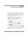
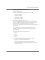
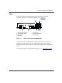
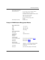
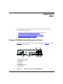
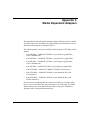
Passport 8190SM Management Module
The Passport 8190SM Switch Management Module (Figure 1-1) provides
centralized management capabilities for the Passport 8010 and 8006 chassis. Use
this module to configure and manage all 8100 Series modules in the chassis.
Console
Management Link
100
Modem (DTE)
1
PCMCIA
Utilization %
Reset
DCE|DTE
25
1
3
2
Power Supply
Master
CPU
2
3
4
50
75
1
100
5
Fan
2
Temp Online
6
9673EA
1 = Ethernet Management Port
2 = DCE/DTE Switch
3 = Console/Modem Ports
4 = Reset Button
5 = PCMCIA Card Slot
6 = LEDs
Figure 1-1.
1-4
Passport 8190SM Switch Management Module
204515-C
About the Passport 8100 Modules
The Passport 8190SM module fits into either slot 5 or slot 6 in the Passport
chassis. Image, configuration, and log files are maintained on the flash memory
(onboard and PCMCIA) of this module. The module also provides out-of-band
management by using the Ethernet port on the module.
Note: Nortel Networks recommends using the Ethernet port on the Passport
8190SM module for management rather than a switched port.
You achieve redundancy by putting a Passport 8190SM module into both slots 5
and 6 of the chassis. When running normally, the second module is in standby
mode. Should the primary Passport 8190SM module fail, the secondary module
initializes while the switch continues to pass traffic. When the secondary Passport
8190SM module completes initialization, it resets the switch with a convergence
time similar to the convergence timing for spanning tree.
The Passport 8190SM module can also be in the chassis with the Passport 8690SF
Switch Fabric Module. The Passport 8690SF module provides layer 3
functionality for 8600 Series modules (routing switch modules). For more
information about the Passport 8690SF module, refer to Using the Passport 8600
Modules.
Note: Although you can mix 8100 Series and 8600 Series modules in the same
chassis, Nortel Networks does not recommend this configuration.
Physical features on the front panel of the Passport 8190SM module include a
management port, DCE/DTE switch for the console port, console port, modem
port, reset button, PCMCIA card slot, and status LEDs.
Ethernet Management Port
The Ethernet Management port on the Passport 8190SM module is an MDI
10/100BASE-T port that allows out-of-band management using a Web browser,
Device Manager and VLAN Manager, or a Telnet session to access the command
line interface (CLI). You can use this port to connect the switch to a network
management station. The port has its own IP address but does not switch traffic to
other ports in the chassis.
204515-C
1-5
Using the Passport 8100 Modules
Note: This port should be used only as a management port. It does not provide
network connectivity.
DTE/DCE Switch
The DTE/DCE switch changes the pin assignments on the Console port and
allows you to designate the connector as either DTE or DCE. For information
about pin assignments for this port, refer to Appendix A, “Technical
Specifications.”
Serial Ports
The Passport 8190SM module provides two serial ports for attachment of modem
or console devices. The Console port provides terminal access to the Passport
8190SM module using the CLI. The Modem port allows you to connect a standard
modem for out-of-band, dial-up management.
For communications specifications used by the serial ports, refer to Appendix A,
“Technical Specifications.”
Reset Button
The recessed reset button on the module allows you to perform a hard reset or
reboot of the system.
PCMCIA Card Slot
The Passport 8190SM module provides a PCMCIA card slot for use with an
ATA-type Sandisk-compatible flash memory card. The flash memory card
provides a convenient way to store switch configurations and boot images. Using
the memory card, you can quickly transfer configurations and images between
multiple switches or store multiple configurations for a single switch.
Note: You cannot use the Passport 1200 PCMCIA card in Passport 8000
Series equipment.
1-6
204515-C
About the Passport 8100 Modules
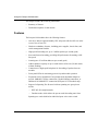
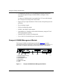
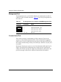
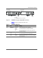
LEDs
LEDs on the Passport 8190SM module indicate the status of the module
subsystems, chassis power supplies, and chassis fans (Figure 1-2).
6
1
Management Link
100
7
Utilization%
3
2
Power Supply
Master
CPU
25
1
2
50
75
100
1
Fan
3
2
Temp Online
4
5
9674EA
1 = Management port LEDs
2 = CPU utilization LEDs
3 = Fan LEDs
4 = Temp LED
Figure 1-2.
5 = Online LED
6 = Power Supply LEDs
7 = Master LED
LEDs on the Passport 8190SM Module
The CPU LEDs serve as a bar graph to indicate module activity. The CPU bar
graph increases when the CPU is actively performing tasks, such as learning
media access control (MAC) addresses or interacting with the device management
station.
For detailed information about the LED meanings, refer to Appendix B, “LEDs.”
204515-C
1-7
Using the Passport 8100 Modules
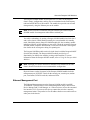
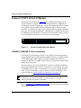
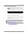
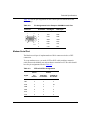
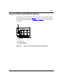
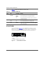
Passport 8132TX 32-Port I/O Module
The Passport 8132TX module (Figure 1-3) is a single-slot I/O module for the
Passport 8000 Series chassis. It has 32 autosensing 10BASE-T/100BASE-TX
switched ports with RJ-45 connectors. The ports have integrated LEDs to indicate
port operation, and the module has three additional LEDs to indicate system
operation. An expansion slot allows you to install an MDA to provide additional
port types. You can add 10/100BASE-T, 100BASE-FX, or Gigabit Ethernet ports
by installing an optional MDA in the Passport 8132TX module. Inserter/extractor
levers and captive retaining screws are at each end of the module.
9155EA
Figure 1-3.
Passport 8132TX Edge Switch Module
10BASE-T/100BASE-TX Port Connectors
The Passport 8132TX module provides 32 10/100 Mb/s autosensing ports that
support the IEEE 802.3u autonegotiation standard. Each port can operate in fullor half-duplex mode. When a port is connected to another device that also
supports the IEEE 802.3u standard, the two devices negotiate the best speed and
duplex mode of operation.
The port connectors are 8-pin modular RJ-45 connectors configured as MDI-X
(media-dependent interface-crossover) connections. You can connect these ports
to an MDI port (for example, a workstation or server) using a straight-through
cable. If you are connecting to a device that does not have an MDI port, use a
crossover cable (see “MDI and MDI-X Connections” on page A-12).
Note: For 10 Mb/s connections, you can use Category 3, 4, or 5 copper
unshielded twisted pair (UTP) cable. Use only Category 5 UTP cable to
connect ports that will operate at 100 Mb/s.
Refer to Appendix A, “Technical Specifications,” for more information about the
RJ-45 port connectors.
1-8
204515-C
About the Passport 8100 Modules
MDA Slot
The MDA slot allows you to install optional media dependent adapters (MDAs)
that support a range of media types. The following MDA versions are available
for the Passport 8132TX module:
•
450-1SR MDA—1000BASE-SX MDA (1-port shortwave gigabit fiber,
with 1 redundant port)
•
450-1SX MDA—1000BASE-SX MDA (1-port shortwave gigabit fiber)
•
450-1LR MDA—1000BASE-LX MDA (1-port longwave gigabit fiber,
with 1 redundant port)
•
450-1LX MDA—100BASE-LX MDA (1-port longwave gigabit fiber)
•
8100-4TX MDA—10BASE-T/100BASE-TX MDA (4-port copper)
•
8100-2FX MDA—100BASE-FX MDA (2-port multimode fiber with
SC connectors)
•
8100-4FX MDA—100BASE-FX MDA (4-port multimode fiber with
MT-RJ connectors)
For information about installing MDAs and specifications for each MDA, refer to
Appendix C, “Media Dependent Adapters.”
Note: The MDAs are hot-swappable in an operating Passport 8132TX
module; however, the module resets when an MDA is inserted or removed.
Comm Port
The Comm port (also called a Console port) allows you to access the CLI if a
Passport 8190SM module is not installed in the chassis. The Comm port is a
mini-DIN serial port connector.
204515-C
1-9
Using the Passport 8100 Modules
Note: Nortel Networks recommends using the Passport 8190SM module to
configure and manage your switch. The Comm port on the Passport 8132TX
module is active only when no Passport 8190SM module is present and when
the Passport 8132TX module is operating as the master module.
The Comm port on the Passport 8132TX module is configured as a data
communications equipment (DCE) connector. Be sure that your RS-232 cable
pinouts are configured for DCE connections.
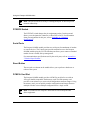
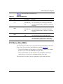
LEDs
The Passport 8132TX module has LEDs (Figure 1-4) to indicate operational
status of the ports and the module. Each port has two integrated LEDs to indicate
link speed and activity for that port. In addition, the module has three LEDs to
indicate system operating conditions.
1
2
3
9120EA
Figure 1-4.
1 = Module LEDs
2 = Port Speed LEDs
3 = Port Link/Activity LEDs
LEDs on the Passport 8132TX Module
For more information about LED operation, refer to Appendix B, “LEDs.”
1-10
204515-C
About the Passport 8100 Modules
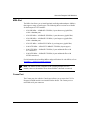
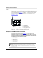
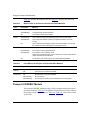
Passport 8148TX 48-Port I/O Module
The Passport 8148TX module provides 48 autonegotiating 10/100 Mb/s ports
(Figure 1-5). Each port can operate in full- or half-duplex mode. Autonegotiation
circuitry automatically negotiates the highest possible data rate and the duplex
operation possible with the attached device, if the attached device supports IEEE
802.3u autonegotiation.
9672EA
Figure 1-5.
Passport 8148TX Edge Switch Module
The port connectors are modular RJ-45 connectors with MDI-X wiring. This port
can be connected to an MDI port (for example, a workstation or server) using a
straight-through cable.
The Passport 8108TX module uses 10BASE-T/100BASE-TX RJ-45 port
connectors to connect to 10 Mb/s or 100 Mb/s Ethernet segments or nodes.
Note: For 10 Mb/s connections, you can use Category 3, 4, or 5 copper
unshielded twisted pair (UTP) cable. Use only Category 5 UTP cable to
connect ports that will operate at 100 Mb/s.
Refer to Appendix A, “Technical Specifications,” for more information about the
RJ-45 port connectors.
204515-C
1-11
Using the Passport 8100 Modules
LEDs
Each port on the Passport 8148TX module has two LEDs that indicate data speed
and activity for the port (Figure 1-6). In addition, the module has three LEDs to
indicate system operating conditions. For details of LED operation, refer to
Appendix B, “LEDs.”
1
2
3
9120EA
Figure 1-6.
1 = Module LEDs
2 = Port Speed LEDs
3 = Port Link/Activity LEDs
LEDs on the Passport 8148TX Module
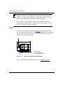
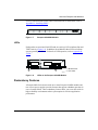
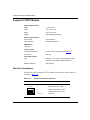
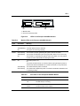
Passport 8108GBIC 8-Port I/O Module
The Passport 8108GBIC I/O module (Figure 1-7) provides eight bays for
installing any of four types of gigabit interface converters (GBICs). These fiber
ports allow you to make riser connection, server attachments, or interswitch links.
The following four types of GBICs are available:
•
1000BASE-SX
•
1000BASE-LX
•
1000BASE-XD
•
1000BASE-ZX
Note: Only Nortel Networks-qualified GBICs are supported for use in the
Passport 8108GBIC module. For specific model numbers, refer to the Nortel
Networks price list.
1-12
204515-C
About the Passport 8100 Modules
For more information about the GBICs and instructions to install them, refer to
Appendix D, “Installing GBICs.”
9681EB
Figure 1-7.
Passport 8108GBIC Module
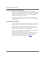
LEDs
Each port has an associated Link LED and Act (activity) LED to indicate link and
TX/RX activity (Figure 1-8). In addition, the module has three LEDs to indicate
system operating conditions. For details of LED operation, refer to Appendix B,
“LEDs.”
8108GBIC
1
8
1 2 3 4 5 6 7 8
Fault
Link
Act
Master
Online
1
1 = Module LEDs
2 = Port LEDs
2
9682EA
Figure 1-8.
LEDs on the Passport 8108GB Module
Redundancy Features
A Passport 8000 Series chassis with one or more Passport 8190SM modules and
two or more power supplies provides features that support redundant operation in
case of certain failures. These redundancy features allow you to use this switch in
high-availability environments where system uptime is critical to application
performance.
204515-C
1-13
Using the Passport 8100 Modules
Redundant Passport 8190SM Modules
When you install two Passport 8190SM modules in a Passport 8000 Series
chassis, one provides the active CPU functions for the switch; the CPU subsystem
on the other module is in standby mode. If the active CPU fails, the standby CPU
assumes the CPU functions for the switch within 1 second. Then the module
relearns the routing databases for the switch.
If two Passport 8190SM modules are installed in the chassis when you turn on
switch power, the module in slot 5 becomes the active CPU; the module in slot 6
is in standby mode.
Redundant Power Supplies
A Passport 8000 Series chassis supports redundant power supplies. Both AC and
DC power supplies are available, and they may be combined in the same chassis.
The Passport 8010 Chassis with more than six installed modules requires a
minimum of two power supplies for a nonredundant configuration. A redundant
configuration for such a chassis requires three power supplies.
In a chassis with a nonredundant power supply configuration, if one power supply
fails, the system loses power and network connectivity.
In a chassis with two installed power supplies, you can add a third power supply
without removing power to the chassis. In a chassis with a redundant power
configuration, you can hot-swap any one power supply while the chassis
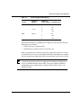
continues to operate with no interruption of service (Table 1-1).
1-14
204515-C
About the Passport 8100 Modules
Table 1-1.
Power Supply Hot-Swapping
Chassis
Number of
Modules
Number of
Hot-Swap One?
Power Supplies
8010
Up to 6
1
No
2
Yes
2
No
3
Yes
1
No
2
Yes
3
Yes
7 to 10
8006
Up to 6
The Passport 8000 Series redundant power supplies provide protection from the
following types of failures:
•
Failure of the power supply module
•
Disconnection or cutting of the AC or DC line cord
When you plug the power cords for each power supply into separate AC circuits
or separate DC power sources, the Passport 8000 Series redundant power supplies
also provide protection against the failure of an individual circuit or power source.
Note: Redundant power supplies are an optional feature, not a requirement.
A single Passport 8000 Series power supply provides adequate operating power
for up to 6 installed modules in the chassis. Two power supplies constitute a
nonredundant power configuration for a Passport 8010 Chassis with 7 to 10
installed modules.
204515-C
1-15
Using the Passport 8100 Modules
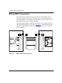
Combining Passport 8100 and Passport 8600 Modules
Although the Passport system software allows you to install both Passport 8100
Series and Passport 8600 Series modules in the same switch chassis, Nortel
Networks does not recommend such a configuration for the following reasons:
1-16
•
Each type of modules functions as a separate switching entity in the chassis,
with no switched connection between the two. To provide connectivity
between the two switch entities, you must make external cable connections.
•
Each CPU module must have its own IP address to allow separate
management of the separate switch entities. When you use Device Manager,
you can manage either the Passport 8100 Series switch or the Passport 8600
Series switch at a given time. The other modules in the chassis are grayed out.
•
The Passport 8190SM module provides management only for Passport 8100
Series edge switch modules. Similarly, the Passport 8690SF module provides
management only for Passport 8600 Series routing switch modules. With two
types of switch modules installed, you cannot install redundant CPUs,
because you must have one each of the Passport 8690SF module and the
Passport 8190SM module.
204515-C
Chapter 2
Installing a Passport 8100 Module
This chapter provides instructions for installing and connecting the Passport 8100
modules in a Passport 8000 Series chassis. For more information about your
chassis, refer to the documentation that was shipped with the chassis.
The initial switch setup tasks are described in Chapter 3, “Basic Switch
Configuration.” For details about configuring a Passport 8100 module, refer to
Getting Started with the Passport 8100 Management Software, Reference for the
Passport 8000 Series Management Software Switching Operations, and Reference
for the Passport 8000 Series Command Line Interface Switching Operations.
This chapter discusses the following topics:
204515-C
•
Chassis configuration requirements (page 2-2)
•
Safety and environmental precautions (page 2-2)
•
Installing a module (page 2-3)
•
Turning on the power (page 2-5)
•
Connecting cables (page 2-6)
•
Replacing modules (page 2-7)
2-1
Using the Passport 8100 Modules
Chassis Configuration Requirements
Slots in the Passport 8000 Series chassis are numbered from the top down, starting
with 1. In either the Passport 8010 or the Passport 8006 chassis, slots 5 and 6 are
reserved for the Passport 8190SM Switch Management Module. Any of the
Passport 8100 Series I/O modules can be installed in the remaining chassis slots.
Note: You must install an I/O module in slot 1 or slot 2 to provide bus master
functions in the switch.
Safety and Environmental Precautions
Before you perform any installation or replacement procedure on the switch,
please note the following safe-handling guidelines:
2-2
•
To prevent damage caused by electrostatic discharge (ESD), handle the switch
chassis and modules only when you, the chassis, and the chassis modules are
properly grounded. Nortel Networks recommends using a grounding wrist
strap.
•
When handling modules, do not touch components on the circuit boards;
always handle modules by their edges. Store unused modules in their
protective packaging.
•
To maintain proper airflow and cooling, always cover unused module slots
and power supply bays with filler panels.
204515-C
Installing a Passport 8100 Module
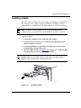
Installing a Module
To install a module in a Passport 8000 Series chassis:
1.
Remove the filler panel from the slot where you will install the module
(Figure 2-1).
9058FA
Figure 2-1.
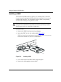
2.
Removing a Filler Panel
Make sure the inserter/extractor levers are extended away from the front
of the module (Figure 2-2).
9397FA
Figure 2-2.
204515-C
Inserter/Extractor Levers in Extended Position
2-3
Using the Passport 8100 Modules
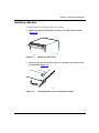
3.
Slide the module into the slot (Figure 2-3).
9398FA
Figure 2-3.
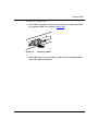
4.
Inserting a Module
Rotate the inserter/extractor levers to seat the module backplane
connectors (Figure 2-4).
9399FA
Figure 2-4.
2-4
Seating the Backplane Connectors
204515-C
Installing a Passport 8100 Module
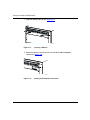
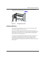
5.
Tighten the retaining screws to secure the module in the chassis
(Figure 2-5).
9400FA
Figure 2-5.
Securing the Module in the Chassis
Turning On the Chassis Power
Although you can install or replace modules in an operating chassis, in a new
installation you may prefer to install all the modules before turning on the chassis
power.
To turn on the chassis power:
1.
Verify that all power cords are connected properly, as described in the
installation instructions for the power supplies.
2.
Turn all the power switches to the On position.
Note: In a chassis with two power supplies in a nonredundant power
configuration, you must turn on both power supply units within 2 seconds of
each other. If you wait longer to turn on the second power supply, both power
supplies will shut down. To correct this condition, turn off both power
supplies, wait at least 30 seconds, and then turn on both power supplies again
within 2 seconds.
204515-C
2-5
Using the Passport 8100 Modules
Connecting Cables
After the modules are installed and the chassis is powered on, connect network
cables. Table 2-1 shows the connector types and recommended cables for each
module.
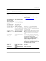
Table 2-1.
Connectors and Cables for Passport 8000 Series Edge Switch Modules
Recommended
Cable Type
Module
Port
Connector
Passport
8190SM
Ethernet
Management
Port
RJ-45
EIA Category 3, 4, or 5
unshielded twisted pair
for 10 Mb/s operation;
EIA Category 5 required
for 100 Mb/s operation
Serial Ports
DB-9
RS-232
10/100 Mb/s
Ethernet Ports
RJ-45 wired EIA Category 3, 4, or 5
as MDI-X
unshielded twisted pair
for 10 Mb/s operation;
EIA Category 5 required
for 100 Mb/s operation
Serial Port
Mini DIN-8
Passport
8148TX
10/100 Mb/s
Ethernet Ports
RJ-45 wired EIA Category 3, 4, or 5
as MDI-X
unshielded twisted pair
for 10 Mb/s operation;
EIA Category 5 required
for 100 Mb/s operation
Passport
8108GBIC
1000 Mb/s
Ethernet port
Duplex SC
Passport
8132TX
Maximum Cable Length
328 ft (100 m)
328 ft (100 m)
RS-232 (Not required if Passport 8109SM module is present)
328 ft (100 m)
Depends on installed GBIC model; for specifications, refer to
Appendix A, “Technical Specifications.”
Note: Ports on the Passport 8132TX and 8148TX modules are wired as
MDI-X. Use straight-through cables to connect these ports to MDI
connections such as workstations or servers. Use crossover cables to connect
these ports to other MDI-X connections such as hubs or other switches.
2-6
204515-C
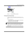
Installing a Passport 8100 Module
Nortel Networks recommends that you route all network cables through the
supplied cable management brackets (Figure 2-6).
9573FA
Figure 2-6.
Routing Network Cables
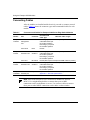
Replacing Modules
Any of the Passport 8100 modules can be removed from an operating switch
chassis without turning off the chassis power.
If you insert a module into the same slot and chassis where the same type of
module was previously installed, the previous configuration is maintained for that
module in that slot. In all other cases, a module inserted into a Passport 8000
series chassis is reset to factory defaults.
If you remove the switch management module (for example, to replace it), the
switch continues switching for up to 2 minutes. Then it reboots using the
configuration settings on the backup switch management module, if one is
present. If no backup switch management is present, after 2 minutes all ports go to
blocking mode.
204515-C
2-7
Using the Passport 8100 Modules
To replace a module:
2-8
1.
Disconnect all network cables from the module to be removed.
2.
Loosen the module retaining screws.
3.
Rotate the inserter/extractor levers to disconnect the module from the
backplane connectors.
4.
Remove the module from the chassis.
5.
Insert the new module in the chassis and tighten the retaining screws.
6.
Reconfigure the ports of the new module as necessary.
7.
Reconnect the cables.
204515-C
Chapter 3
Basic Switch Configuration
This chapter describes how to use the command line interface (CLI) for basic
switch configuration. The chapter includes the following information:
•
Port numbering (page 3-2)
•
Booting the switch (page 3-3)
•
Logging on to the system (page 3-4)
•
Assigning an IP address to the Management port (page 3-5)
•
Setting system identification (page 3-5)
•
Setting system security (page 3-6)
•
Sample configuration (page 3-8)
For information about more advanced configuration topics, refer to the following
publications:
•
Networking Concepts for the Passport 8000 Series Switch
•
Reference for the Passport 8000 Series Management Software Switching
Operations
•
Reference for the Passport 8000 Series Command Line Interface Switching
Operations
Note: To perform configuration procedures, you must log on to the switch
with Read-Write privileges.
204515-C
3-1
Using the Passport 8100 Modules
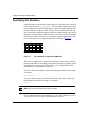
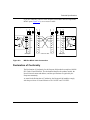
Specifying Port Numbers
Each port number on the Passport switch consists of a slot number and a position
number in the format <slot>/<position>. The slot number identifies the chassis
slot containing the I/O module with that port. The position number identifies the
position of the port on the I/O module. Chassis slots are numbered from the top
down, and ports are numbered generally from left to right beginning with 1 for the
far left port. On high-density modules with two rows of ports, such as the Passport
8148TX module, ports in the top row are assigned sequential odd numbers, and
ports in the bottom row are assigned sequential even numbers (Figure 3-1).
9494EA
Figure 3-1.
Port Numbers on High-Density Modules
MDA ports are numbered as a continuation of the ports on the module, and port
numbers on an MDA are in ascending order from left to right. For example, the far
left MDA port in a Passport 8132TX module is port 33. Gigabit MDAs with
redundant PHYs are regarded as a single port.
To specify a list of port numbers, separate individual port numbers with commas.
For example:
3/4,7/22,10/47
To specify a range of ports, type the low port number in the range, a dash, and
then the high port number in the range. For example:
3/4-3/16
Note: Spaces are not allowed in port lists or ranges.
For more information about port numbering as well as MAC addressing, refer to
Getting Started with the Passport 8100 Management Software.
3-2
204515-C
Basic Switch Configuration
Booting the Switch
When you turn on the switch power supplies, the switch begins its automatic boot
process. The default boot order is to try to boot the switch first from the PCMCIA
card, then from the internal flash memory, and finally over the network. If a
terminal is connected to the Console port, you can watch the system messages that
record the boot sequence. You can modify this boot order using the boot monitor
command line interface (CLI).
While the Passport 8190SM module is booting, the I/O modules boot using their
local image files, which check for the presence of a Passport 8190SM module in
the chassis. When the Passport 8190SM module has completed its boot process,
the I/O modules transmit a load request. Messages on the console screen indicate
the request and the completion of the image load. Then the I/O modules reboot
using the newly loaded image. The entire boot sequence for the switch can take up
to one minute.
When the switch starts booting, you can access the boot monitor by pressing any
key during the first 4 seconds of the boot sequence. For details about the boot
monitor and using the command line interface to modify the boot process, refer to
Getting Started with the Passport 8100 Management Software and Reference for
the Passport 8000 Series Command Line Interface Switching Operations.
204515-C
3-3
Using the Passport 8100 Modules
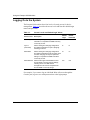
Logging On to the System
The Passport 8100 switches have four levels of security access for device
management. Table 3-1 describes the access levels and lists their default login
names and passwords.
Table 3-1.
Access Levels and Default Login Values
Default
Login
Default
Password
Access Level
Description
Read-Only
Allows only viewing of configuration and status ro
information. Is equivalent to SNMP read-only
community access.
ro
Layer 2
(read-write)
Allows viewing and changing configuration
and status information for layer 2 (bridging/
switching) functions.
l2
l2
Read-Write
Allows viewing and changing configuration
rw
and status information across the switch; does
not allow changing security and password
settings. Is equivalent to SNMP read-write
community access.
rw
Read-Write-All
Allows all the rights of Read-Write access
and the ability to change security settings,
including the CLI and Web-based
management user names and passwords
and the SNMP community strings.
rwa
rwa
For example, if you want to log on with Read-Write-All access through the
Console port, log on as rwa with password rwa at the login prompt.
3-4
204515-C
Basic Switch Configuration
Assigning an IP Address to the Management Port
You must assign an IP address to the Management port before you can use it for
out-of-band management.
To assign an IP address:
•
Use the following command:
config bootconfig net mgmt ip <addr/mask>
where:
<addr/mask>
specifies the IP address and mask of the Console Management
port.
Note: The preferred route for managing the switch is to use the Management
port.
Setting System Identification
System identification parameters specify the system name, contact person, and
location.
To set the system identification:
1.
Specify the system name using the command:
config sys set name <prompt>
where <prompt> is an ASCII string specifying the system name and box or
root level prompt.
2.
Specify the name of the contact person for the switch using the
command:
config sys set contact <contact>
where <contact> is an ASCII string specifying the name of the person.
3.
Define the location for the system with the command:
config sys set location <location>
where <location> is an ASCII string specifying the system location.
204515-C
3-5
Using the Passport 8100 Modules
Setting System Security
System security parameters allow you to define login names and passwords for
access to the switch management functions and to specify the access methods,
such as through a Telnet session or through a Web browser.
To set system security:
1.
Change CLI users and passwords using the following commands:
•
config cli password ro <username>[<password>]—changes
the
Read-Only login and/or password.
•
config cli password l2 <username>[<password>]—changes
the
Layer 2 Read-Write login and/or password.
•
config cli password rw <username>[<password>]—changes
the
Read-Write login and/or password.
•
config cli password rwa <username>[<password>]—changes
the
Read-Write-All login and/or password.
where:
2.
username
is the login name.
password
is the password associated with the login name.
Change SNMP community strings using the command:
config sys set snmp community <ro|rw|l2|rwa> <commstr>
where:
<ro|rw|l2|rwa> is the choice of community—ro is Read-Only, rw is
Read-Write, l2 is Layer 2 Read-Write, and rwa is Read-Write-All.
<commstr>
3.
3-6
is the input community string {string}.
Enable or disable Web access using the commands:
•
config web-server disable
•
config web-server enable
to turn off Web access
to turn on Web access
204515-C
Basic Switch Configuration
4.
Change Web passwords using the command:
config web-server set password ro <username> <passwd>
where:
<username>
<passwd>
is the user’s login name, up to 20 characters long.
is the password associated with the login name, up to 20 characters
long.
To enable or disable Telnet access, you set flags from the boot monitor CLI. You
can access the boot monitor CLI while the switch is booting.
To set up Telnet access:
1.
While the switch is booting, press any key to interrupt the autoboot
process.
2.
Enable or disable Telnet access using the command:
flags telnetd <true|false>
where:
true enables
false
204515-C
Telnet access.
disables Telnet access.
3-7
Using the Passport 8100 Modules
Switch Configuration
The Passport 8100 Series modules provide layer 2 switching as soon as you install
them and turn on the switch power. The default configuration includes a single
VLAN with a VLAN ID of 1 that contains all the ports in the switch.
The only configuration you need to do for the Passport 8100 Series switch is to
assign an IP address and a gateway address (default route) for remote
management.
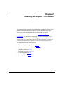
Configuring the Passport switch as a layer 2 switch consists of the following
tasks:
•
•
•
•
Confirm that all ports are in the default VLAN.
Assign an IP address for management.
Specify a default gateway address or default route.
Test connectivity.
To configure the switch as a layer 2 (bridging/switching) device:
1.
Confirm that all ports are in the default VLAN using the command:
show vlan info ports
The display shows the VlanId (1) and lists the port members.
2.
To assign an IP address for management, use the command:
config bootconfig net mgmt ip <ipaddr/mask>
where:
is the IP address/subnet mask you are assigning (for
example, 10.10.10.1/24).
<ipaddr/mask>
Alternatively, you can assign an IP address to the default VLAN (VLAN ID
1) using the command config vlan 1 ip create <addr/mask>.
Note: Nortel Networks does not recommend assigning an IP address to
the default VLAN. Management response is significantly degraded by
managing the switch through the default VLAN.
3-8
204515-C
Basic Switch Configuration
3.
Specify a default gateway address/default route.
When configuring IP on most layer 2 switches, you need to specify the IP
address of the device and the IP address of the default gateway.
Use the following Boot Monitor CLI command to specify the default route:
net mgmt route net 0.0.0.0 <ipaddr>
Use the following Run-Time CLI command to specify the default route:
config bootconfig net mgmt route net 0.0.0.0 <ipaddr>
In each of these commands, ipaddr specifies the IP address of the default
gateway.
4.
To save the configuration, enter:
save config
Your Passport 8100 switch now has an IP address and can be used as a layer 2
switch.
204515-C
3-9
Chapter 4
Troubleshooting
This chapter describes troubleshooting techniques for the Passport 8100 modules.
This chapter includes information about the following topics:
•
Normal power-up sequence (this page)
•
Failure to get a login prompt (page 4-2)
•
Failure of the management software to recognize I/O modules (page 4-2)
•
LED indications of problems (page 4-2)
•
Port connection problems (page 4-4)
•
Installation issues (page 4-7)
Normal Power-Up Sequence
In a normal power-up sequence, the LEDs display as follows:
1.
When power is applied to the switch, the green LED on each power supply
and fan tray turns on within 5 seconds.
2.
Each module initiates a self-test, during which the port and module LEDs
display various patterns to indicate the progress of the self-test.
3.
Upon successful completion of the self-test (within 10 seconds after power is
applied), the Online LED lights.
For information about the other LEDs on the Passport 8132TX, 8148TX,
8108GBIC, and 8190SM modules, refer to Appendix B, “LEDs.”
204515-C
4-1
Using the Passport 8100 Modules
Failure to Get a Login Prompt from the Console Port
If you have connected a terminal to the Console port on the Passport 8190SM
module and fail to get a login prompt, the port may have an incorrect DCE/DTE
setting. Try moving the DCE/DTE switch from its current setting to the other
position (Figure 4-1).
Console
ink
00
DCE|DTE
9595EA
Figure 4-1.
DCE/DTE Switch on the Passport 8190SM Module
Failure of Management Software to Recognize I/O Modules
If management software does not recognize the presence of any I/O modules in
the switch, the device view in Device Manager, for example, shows a switch with
only a management module installed. This situation can occur when no I/O
module is installed in slot 1 or slot 2 of the chassis. A Passport 8000 Series chassis
must have an I/O module installed in slot 1 or slot 2 of the chassis to provide bus
master functions for the switch.
LED Indications of Problems
If the switch is not operating properly, LEDs may provide information about the
probable cause. Table 4-1 lists possible problems as indicated by LEDs on the
switch modules and suggests corrective action.
4-2
204515-C
Troubleshooting
Table 4-1.
LED Indications of Problems
Symptom
Probable Cause
Corrective Action
Green power supply
LEDs are off.
The switch is not receiving
AC power.
Verify that each AC power cord is fastened
securely at both ends and that power is available
at each AC power outlet. Verify that each power
supply is turned on.
The Link/Activity LED
for a connected port is
off or does not blink
(and you have reason to
believe that traffic is
present).
The switch is experiencing
a port connection problem.
See “Port Connection Problems” next.
The switch’s link partner is
not autonegotiating properly.
The Link/Activity LED
blinks continuously.
There may be a port
configuration error.
The Online LED on an
I/O module is yellow.
Software incompatibility
exists, or the module cannot
communicate with the master
module over the backplane.
Use the show log command to check the
system log for indications of communication
problems. Use the boot command to download a
new software image.
The Master LED on a
This module has detected
module in slot 1 or slot 2 system clock generation
is yellow.
failure on its own circuitry.
Replace the module; make sure it is in the correct
slot.
Note: This LED refers only to the module in slot 1
or slot 2 that provides the clock function for the
switch.
The Fault LED is
blinking yellow.
A chassis failure has been
detected.
From the console management station, use the
show log command to check the system log for
information about hardware failures
Check the fans in the Passport 8100 module
chassis to make sure both are running.
Check the switch power supplies; one may have
stopped functioning.
The module may have failed to read the MAC
address from the chassis backplane. If this is the
case, arrange to replace the chassis.
The Fault LED is
steadily yellow.
A diagnostics failure or
hardware failure has been
detected.
The module failed its power-on self-test. Replace
the module.
No LEDs are lit.
A hardware failure has been
detected.
Power cycle the switch.
204515-C
4-3
Using the Passport 8100 Modules
Port Connection Problems
Port connection problems can usually be traced to a poor cable connection or to an
improper connection of the port cables at either end of the link. These types of
problems can be remedied by making sure that the cable connections are secure
and that the cables are connected to the correct ports at both ends of the link.
For more information about cabling, see “Cabling,” next in this chapter.
Port connection problems can also be traced to the autonegotiation mode (refer to
“Autonegotiation Modes” on page 4-5) or the port interface.
Cabling
Cabling for 10BASE-T networks can consist of 2-pair Category 3, 4, or 5
unshielded twisted pair (UTP) wiring. However, to cover future upgrades to Fast
Ethernet, Nortel Networks strongly recommends that you use all Category 5 cable
in your network.
Ethernet 10BASE-T network installations use cables consisting of two pairs of
twisted pair wires—one pair to send data and one to receive data. These wires
must connect to another 10BASE-T station that has the sending pair attached to its
receiving pair and vice versa. In this way, the two nodes can exchange data. If the
two nodes are wired alike, they both attempt to send data out on the same
RJ-45 pins. In such a case, a straight-through cable would not work. However, a
crossover cable would operate normally.
The Passport 8100 Series modules are designed to have Ethernet NICs connect
directly to their RJ-45 ports using straight-through (MDI) cables. However, if a
Passport 8100 module must connect to a hub or another switch that follows usual
conventions, a crossover cable (MDI-X) is required.
The 100 Mb/s ports are designed to operate using Category 5 UTP cabling only.
Category 5 UTP cable is a 2-pair cable certified to handle up to 100 Mb/s
bandwidth. To minimize crosstalk noise, maintain the twist ratio of the cable up to
the point of termination; untwist at any termination should not exceed 0.5 inch
(1.27 cm).
For best performance with respect to noise immunity and emissions, the unused
pairs in the 2-pair cable should be terminated at their characteristic impedance
(that is, 100 ohms) in the equipment at each end of the cable. All Nortel Networks
100BASE-TX equipment includes such a Common Mode Termination (CMT).
4-4
204515-C
Troubleshooting
The fiber MDAs use only multimode 62.5/125 µm fiber cable. The Nortel
Networks 100BASE-FX MDA is not supported on single-mode fiber. SC
connectors are used on 2-port 100BASE-FX MDAs, and MT-RJ connectors are
used on 4-port 100BASE-FX MDAs.
Cables for the GBICs vary depending on the specific GBIC type. For details of the
cable requirements for GBICs, refer to Appendix A, “Technical Specifications.”
Autonegotiation Modes
Port connection problems can occur when a port (or station) is connected to
another port (or station) that is not operating in a compatible mode (for example,
connecting a full-duplex port on one station to a half-duplex port on another
station).
The Passport 8100 modules negotiate port speeds according to the IEEE 802.3u
autonegotiating standard. The switch adjusts (autonegotiates) its port speed and
duplex mode to match the best service provided by the connected station, up to
100 Mb/s in full-duplex mode.
The following autonegotiation problems can occur:
•
If the connected station uses a form of autonegotiation that is not compatible
with the IEEE 802.3u autonegotiating standard, the Passport 8100 module
cannot negotiate a compatible mode for correct operation.
•
If the autonegotiation feature is not present or is not enabled at the connected
station, the Passport 8100 module may not be able to determine the correct
duplex mode.
In both situations, the Passport 8100 module autosenses the speed of the
connected station and, by default, reverts to half-duplex mode. If the connected
station is operating in full-duplex mode, it cannot communicate with the switch.
204515-C
4-5
Using the Passport 8100 Modules
To correct this mode mismatch problem:
1.
Use the CLI to disable autonegotiation for the suspect port.
Refer to Reference for the Passport 8000 Command Line Interface Switching
Operations for the appropriate CLI commands.
2.
Use the CLI to set the speed and duplex mode of the port to match the
speed/duplex mode of the connected station.
You may have to try several settings before you find the correct speed/duplex
mode of the connected station.
If the problem persists, follow these additional steps:
1.
Using the CLI, disable the autonegotiation feature at the connected
station.
2.
Manually set the speed/duplex mode of the connected station to the same
speed/duplex mode you have manually set for the Passport 8100 module
port.
Note: Nortel Networks recommends that you manually set the Passport 8100
module port to the desired speed/duplex mode when connecting to any of the
following Nortel Networks products:
• Nortel Networks 28000 product family
• Nortel Networks 58000 product family
• BayStack™ 302T switch (100 Mb/s port)
Port Interface
Verify that the devices are connected using the appropriate crossover or
straight-through cable. (For information about appropriate cables, refer to
Appendix A, “Technical Specifications.”)
4-6
204515-C
Troubleshooting
Installation-Related Issues
Ethernet networks tend to be fairly simple, but they can still have problems that
take time to resolve. The most common problems are associated with the actual
network wiring.
If you have problems with a newly established network (initial setup), the trouble
is most likely related to cabling or addressing. If the network has been operational
for an extended period and is now beginning to have problems, the trouble is
probably related to recent additions or changes.
Addresses
Remember that each Passport 8100 module or Passport 8000 Series switch has a
media access control (MAC) station address and an IP address. The MAC station
addresses are unique because each address contains the Nortel Networks
manufacturer ID and node ID codes.
A valid IP address is not required for normal switching operation or if you are
managing the switch from a console. However, for management over the network
(SNMP or Telnet session), a valid IP address is required.
You can change the IP address of the unit to match your own network addressing
structures. Make sure that the IP address of the Passport 8100 module or Passport
8000 Series switch is unique in your network. You can change the IP address
using the config ip address command (refer to “Assigning an IP Address to the
Management Port” on page 3-5). You will need to set a valid IP address if you
intend to use network management with SNMP or Telnet.
204515-C
4-7
Appendix A
Technical Specifications
This appendix lists technical specifications for the Passport 8100 modules. The
appendix includes the following information:
•
•
General specifications
Specifications for individual modules, including:
— Physical specifications
— Connector types and, where appropriate, pin assignments
— Required cables
•
•
MDI and MDI-X connections
Declaration of Conformity
General Specifications
Standards Supported
IEEE 802.3 CSMA/CD (ISO/IEC 8802-3)
IEEE 802.3i 10BASE-T (ISO/IEC 8802-3)
IEEE 802.3u 100BASE-TX (ISO/IEC 8802-3)
IEEE 802.1D MAC Bridges (ISO/IEC 10038)
IEEE 802.1p (Prioritization)
IEEE 802.1Q (VLAN Tagging)
IEEE 802.1z (Gigabit)
IEEE 802.3z 1000BASE-SX and 1000BASE-LX (Draft Standard ver. 3.1)
IEEE 802.3x on Gigabit ports
204515-C
A-1
Using the Passport 8100 Modules
Data Rate and Encoding
10 Mb/s Manchester encoding
100 Mb/s 4B/5B encoding
1000 Mb/s 8B/10B encoding
Environmental Specifications
Operating Temperature:
5° to 40° C (41° to 104° F)
Storage Temperature:
–25° to 70° C (–13° to 158° F)
Operating Humidity:
85% maximum relative humidity, noncondensing
Storage Humidity:
95% maximum relative humidity, noncondensing
Operating Altitude:
3000 m (10,000 ft) maximum
Free Fall/Drop:
ISO 4180-s, NSTA 1A
Vibration:
IEC 68-2-6/34
Shock/Bump:
IEC 68-2-27/29
Performance Specifications (64-byte packets)
Aggregate Throughput:
3,000,000 pps maximum
Switched Forwarding Rates:
For 10 Mb/s: 14,880 pps maximum
For 100 Mb/s: 148,810 pps maximum
For 1000 Mb/s: 1,488,100 pps maximum
Latency:
9 ms
Address Database Size
Addressing:
48-bit MAC address
Frame Length:
64 to 1518 bytes (IEEE 802.1Q Untagged)
64 to 1522 bytes (IEEE 802.1Q Tagged)
Safety Agency Approvals
UL Listed (UL 1950)
CUL CSA 22.2 No. 950
CB with all national deviations
NOM NOM-019-SCFI 1994
A-2
204515-C
Technical Specifications
Electromagnetic Emissions
Meets requirements of:
US: FCC CFR 47, Part 15, Subpart B, Class A
Canada: ICES-003, Issue-2, Class A
Australia/New Zealand: AS/NZS 3548:1995, Class A
Japan: VCCI V-3/97.04, Class A
Taiwan: CNS 13438, Class A
EN 55 022 (CISPR 22:1985), Class A
CE Mark
Electromagnetic Immunity:
EN50082-1:1997
Passport 8190SM Switch Management Module
Physical Specifications
Height:
1.5 in. (3.8 cm)
Width:
15.4 in. (39.1 cm)
Depth:
18.5 in. (47.0 cm)
Weight:
7 lb (3.15 kg)
Electrical Specifications
Input Current:
75 W
Thermal Rating:
250 BTU/hr maximum
MTBF Rating
229,623 hr
Connector Types
Ethernet Management port:
RJ-45 connector wired as MDI-X (Table A-1)
Console port:
DB-9 connector (Table A-2)
Modem port:
DB-9 connector (Table A-3)
Required Cables
204515-C
Ethernet Management port:
Category 3, 4, or 5 UTP cable (10 Mb/s operation)
Category 5 UTP cable (100 Mb/s operation)
Console port:
RS-232 cable
Modem port:
DTE-to-DCE cable (straight or transmit cable)
A-3
Using the Passport 8100 Modules
Management Port
The Management port is a 10/100 Mb/s Ethernet port implemented on an RJ-45
connector wired as an MDI connection. Table A-1 shows the pin assignments for
this connector.
Table A-1.
Connector
12345678
8020EA
Pin Assignments in the Passport 8190SM Management Port
Pin Number
Signal
1
Output transmit data + (TX+)
2
Output transmit data - (TX-)
3
Input receive data + (RX+)
6
Input receive data - (RX-)
4, 5, 7, 8
Not used
Console Serial Port
The Console serial port is implemented as a DB-9 connector. This port can
operate as a data terminal equipment (DTE) or data communication equipment
(DCE) device. Use the switch to the left of the port to set the port to DTE (left) or
DCE (right). Default settings for this port are 9600 bps, 8 data bits, no parity, and
one stop bit.
Because the Console port expects to receive Data Set Ready (DSR) and Clear To
Send (CTS) signals before transmitting, these control lines are required in the
cabling. The Console port does not support any inbound flow control; that is, the
port does not toggle control lines to indicate an input buffer full condition.
A-4
204515-C
Technical Specifications
Table A-2 lists the pin assignments for the Console port for both the DTE and
DCE settings.
Table A-2.
Pin Assignments in the Passport 8190SM Console Port
Connector
1
6
5
9
9473EA
Pin Number
DCE Signal
DTE Signal
2
RXD
TXD
3
TXD
RXD
4
DTR
DSR
5
GND
GND
6
DSR
DTR
7
RTS
CTS
9
CTS
RTS
Modem Serial Port
The Modem serial port is implemented on a DB-9 connector wired as a DTE
connection.
To set up modem access, you need a DTE-to-DCE cable (straight or transmit
cable) between the Modem port and a modem or terminal server. The cable should
have the pin assignments listed in Table A-3.
Table A-3.
DTE-to-DCE Pin Assignments
Switch
Pin
Number
DCE DB-9
Pin Number
DCE DB-25
Pin Number
RXD
2
2
3
TXD
3
3
2
DTR
4
4
20
GND
5
5
7
DSR
6
6
6
RTS
7
7
4
CTS
9
9
5
Signal
204515-C
Modem
A-5
Using the Passport 8100 Modules
Passport 8132TX Module
Physical Specifications
Height:
1.5 in. (3.8 cm)
Width:
15.4 in. (39.1 cm)
Depth:
18.5 in. (47.0 cm)
Weight:
8.06 lb (4 kg approximate)
Electrical Specifications
Input Current:
75 W maximum
Thermal Rating:
250 BTU/hr maximum
MTBF Rating
122,000 hr
Connector Type
10/100 Ethernet Ports:
RJ-45 connector wired as MDI-X (Table A-4)
Comm Port:
Mini-DIN
Cable Specifications
Type:
Category 3, 4, or 5 UTP cable (10 Mb/s operation)
Category 5 UTP cable (100 Mb/s operation)
Maximum Distance:
328 ft (100 m)
Data Port Connectors
The data ports on the Passport 8132TX module are RJ-45 ports wired as MDI-X
connectors (Table A-4).
Table A-4.
Passport 8132TX Port Pinouts
Connector
12345678
Pin Number
Signal
1
Input receive data + (RX+)
2
Input receive data - (RX-)
3
Output transmit data + (TX+)
6
Output transmit data - (TX-)
4, 5, 7, 8
Not used
8020EA
A-6
204515-C
Technical Specifications
Comm Port Connector
The cable used to connect the comm port is a serial cable with a mini-DIN
connector on one end to connect to the Passport 8132TX comm port and a DB-25
connector on the other to connect to a terminal or computer. This cable and a
DB-25 to DB-9 adapter are shipped with the Passport 8000 Series chassis.
Note: The Comm port on the Passport 8132TX module is active only when
the chassis has no installed Passport 8190SM module. You should not use this
port for managing the switch if you are using software version 2.0 or later.
MDAs
450-1SR MDA, 450-1SX MDA
Required Cable:
Multimode fiber optic
Maximum distance:
1804 ft (550 m)
Wavelength:
850 nm
Average Transmit Output Power:
-9.5 to -4 dBm
Average Receiver Sensitivity:
-17 dBm (minimum)
450-1LR MDA, 450-1LX MDA
204515-C
Required Cable:
Multimode fiber optic
Maximum distance:
1804 ft (550 m)
Wavelength:
1300 nm
Average Transmit Output Power:
-5.2 to 0 dBm
Average Receiver Sensitivity:
-22 dBm (minimum)
A-7
Using the Passport 8100 Modules
Passport 8148TX Module
Physical Specifications
Height:
1.5 in. (3.8 cm)
Width:
15.4 in. (39.1 cm)
Depth:
18.5 in. (47.0 cm)
Weight:
9 lb (4 kg)
Electrical Specifications
Input Current:
75 W maximum
Thermal Rating:
250 BTU/hr maximum
MTBF Rating
72,213
Connector Type
RJ-45 connector wired as MDI-X (Table A-5)
Cable Specifications
Type:
Category 3, 4, or 5 UTP cable (10 Mb/s operation)
Category 5 UTP cable (100 Mb/s operation)
Maximum Distance:
328 ft (100 m)
Port Connectors
The ports on the Passport 8148TX module are RJ-45 ports wired as MDI-X
connectors (Table A-5).
Table A-5.
Passport 8148TX Port Pinouts
Connector
12345678
Pin Number
Signal
1
Input receive data + (RX+)
2
Input receive data - (RX-)
3
Output transmit data + (TX+)
6
Output transmit data - (TX-)
4, 5, 7, 8
Not used
8020EA
A-8
204515-C
Technical Specifications
Passport 8108GBIC Module
Physical Specifications
Height:
1.5 in. (3.8 cm)
Width:
15.4 in. (39.1 cm)
Depth:
18.5 in. (47.0 cm)
Weight:
8 lb (4 kg)
Electrical Specifications
Input Current:
65 W maximum
Thermal Rating:
224 BTU/hr maximum
MTBF Rating
93,284 hr
Connector Type
Duplex SC
GBICs
Physical Specifications
Height:
12 mm
Width:
30 mm
Depth:
65 mm
Weight:
Varies with GBIC type
Connector Type
Duplex SC
204515-C
A-9
Using the Passport 8100 Modules
1000BASE-SX GBIC
Cable Specifications
Type:
62.5 µm or 50 µm multimode fiber
Maximum Distance:
1804 ft (550 m)
Optical Specifications
Wavelength:
850 nm (VCSEL)
Average Transmit Output Power:
-9.5 to -4 dBm
Average Receiver Sensitivity:
-17 dBm (minimum)
1000BASE-LX GBIC
Cable Specifications
Type
62.5 µm multimode fiber or
9 µm single-mode fiber
Note: Multimode fiber may require a DMD patch
cord.
Maximum Distance:
Single-mode fiber: 32,810 ft (10 km)
Multimode fiber: 1804 ft (550 m)
Optical Specifications
A-10
Wavelength:
1300 nm (FP laser diode)
Average Transmit Output Power:
-5.2 to 0 dBm
Average Receiver Sensitivity:
-22 dBm (minimum)
204515-C
Technical Specifications
1000BASE-XD GBIC
Cable Specifications
Type:
9 µm single-mode fiber
Maximum Distance:
31 mi (50 km)
Note: For a shorter link distance, you may need an
in-line attenuator to prevent overloading the
receiver.
Optical Specifications
Wavelength:
1550 nm (DFB laser diode)
Average Transmit Output Power:
-5.2 to 0 dBm
Average Receiver Sensitivity:
-24 dBm
1000BASE-ZX GBIC
Cable Specifications
Type:
9 µm single-mode fiber
Maximum Distance:
43 mi (70 km)
Note: For a shorter link distance, you may need an
in-line attenuator to prevent overloading the
receiver.
Optical Specifications
204515-C
Wavelength:
1550 nm (DFB laser diode)
Average Transmit Output Power:
0 to 5.2 dBm
Average Receiver Sensitivity:
-22 dBm (minimum)
A-11
Using the Passport 8100 Modules
MDI and MDI-X Connections
For communication to take place between two devices, the transmitter of one
device must connect to the receiver of the other device. The connection must be
achieved through a crossover function, which could be a crossover cable or a port
that implements the crossover function internally.
The Passport 8100 modules use MDI-X ports that allow you to connect directly to
end stations without using crossover cables (Figure A-1). Ports that implement the
crossover function internally are known as MDI-X ports (where “X” refers to the
crossover function).
Passport 8000 switch
1
8
T
R
End station
8
1
8
1
1
8
1 RX+
1
1
TX+
1
2 RX-
2
2
TX-
2
3 TX+
3
3
RX+
3
4
4
4
4
5
5
5
5
6 TX-
6
6
7
7
7
7
8
8
8
8
MDI-X port
Straight-through cable
RX-
T
R
6
MDI port
617EF
Figure A-1.
A-12
MDI-X to MDI Cable Connections
204515-C
Technical Specifications
If you are connecting a device to the Passport 8100 module that also implements
MDI-X ports (Figure A-2), use a crossover cable.
Passport 8000 switch
1
8
T
R
8
1
8
Switch or hub
8
1
1
1 RX+
1
1
RX+
1
2 RX-
2
2
RX-
2
3 TX+
3
3
TX+
3
4
4
4
4
5
5
5
5
6 TX-
6
6
7
7
7
7
8
8
8
8
MDI-X port
Crossover cable
TX-
T
R
6
MDI-X port
618EF
Figure A-2.
MDI-X to MDI-X Cable Connections
Declaration of Conformity
The Declaration of Conformity for the Passport 8100 modules complies with ISO/
IEC Guide 22 and EN45014. The declaration identifies the product models, the
Nortel Networks name and address, and the specifications recognized by the
European community.
As stated in the Declaration of Conformity, the Passport 8100 modules comply
with the provisions of Council Directives 89/336/EEC and 73/23/EEC.
204515-C
A-13
Appendix B
LEDs
This appendix describes the LED locations and meanings for the following
Passport 8000 Series modules:
•
Passport 8190SM Switch Management Module (this page)
•
Passport 8132TX and 8148TX I/O Modules (page B-3)
•
Passport 8108GBIC Module (page B-4)
Passport 8190SM Switch Management Module
Figure B-1 shows the LEDs on the Passport 8190SM module. Table B-1 describes
the operation of these LEDs.
6
1
Management Link
100
7
Utilization%
3
2
Power Supply
Master
CPU
25
1
2
50
75
100
1
Fan
3
2
Temp Online
4
5
9674EA
1 = Management port LEDs
2 = CPU utilization LEDs
3 = Fan LEDs
4 = Temp LED
5 = Online LED
6 = Power Supply LEDs
7 = Master LED
Figure B-1.
204515-C
LEDs on the Passport 8190SM Module
B-1
Using the Passport 8100 Modules
Table B-1.
Label
Color/State
Meaning
Link
Green/Steady
The management port is connected, and the link is
good.
Off
There is no link to the management port.
Green/Steady
The management port is operating at 100 Mb/s.
Off
The management port is operating at 10 Mb/s.
Utilization %
(8 LEDs)
Green
The number of lit LEDs indicates the level of CPU
activity.
Power Supply
1, 2, 3
Off
A power supply is not present in the specified
position, or the power supply in the specified
position is not turned on.
Green/Steady
The specified power supply is operating normally.
Amber/Steady
The specified power supply has a fault.
Green/Steady
The specified fan is operating normally.
Amber/Steady
The specified fan has failed.
Green/Steady
The temperature is normal for switch operation.
Amber/Steady
The maximum operating temperature has been
exceeded.
Off
The CPU subsystem on the module is performing
diagnostics.
Amber/Steady
The CPU subsystem is in a fault state.
Green/Blinking
This module is providing active CPU functions for
the switch.
Green/Steady
The CPU subsystem on this module is up and in
standby mode.
Off
This LED is always off during operation of the
Passport 8190SM module.
100
Fan 1, 2
Temp
Master
Online
B-2
LED Operation on the Passport 8190SM Module
204515-C
LEDs
Passport 8132TX and 8148TX I/O Modules
The Passport 8132TX and 8148TX modules have three LEDs to indicate module
and system operating conditions (Table B-2). In addition, each port has two LEDs
to indicate data speed and link status (Table B-3). Figure B-2 shows the locations
of the LEDs.
1
2
3
9120EA
1 = Module LEDs
2 = Port LEDs: Speed
3 = Port LEDs: Link/Activity
Figure B-2.
204515-C
LEDs on the Passport 8132TX and 8148TX Modules
B-3
Using the Passport 8100 Modules
Table B-2 describes the module LEDs, and Table B-3 describes the port LEDs.
Table B-2.
Module LEDs on the Passport 8132TX and 8148TX Modules
Label
Color/State
Meaning
Fault
Yellow/Steady
A diagnostics failure or hardware failure has been detected.
Yellow/Blinking
A chassis failure has been detected.
Off
The system is functioning normally.
Green/Steady
This module is properly generating the system clock for the switch.
Yellow/Steady
This module has detected system clock generation failure on its own
circuitry.
Off
This module is not providing the system clock for the switch. You can pull
this module out of the chassis without resetting the switch.
Green/Steady
The module is functioning normally and is in switching mode.
Green/Blinking
The module is running diagnostic tests.
Yellow/Steady
The module is not in switching mode.
Software incompatibility exists, or the module cannot communicate with the
master module over the backplane.
Off
The module is not receiving power or is administratively disabled.
Master
Online
Table B-3.
Port LEDs on the Passport 8132TX and 8148TX Modules
LED
Color/State
Meaning
10/100
(Speed)
Green/Steady
The port is set to operate at 100 Mb/s.
Off
The port is set to operate at 10 Mb/s.
Link/Activity
Off
No link exists, or the port is disabled.
Green/Steady
The link is good.
Green/Blinking
The link is good, and the port is transmitting or receiving traffic.
Passport 8108GBIC Module
The Passport 8108GBIC module has three LEDs to indicate module and system
operating conditions (Table B-4). In addition, each port has two LEDs to indicate
the presence of link and data activity (Table B-5). Figure B-3 shows the locations
of the LEDs.
B-4
204515-C
LEDs
8108GBIC
1
8
1 2 3 4 5 6 7 8
Fault
Link
Act
Master
Online
1
2
9682EA
1 = Module LEDs
2 = Port Link and Activity LEDs
Figure B-3.
Table B-4.
LEDs on the Passport 8108GBIC Module
Module LEDs on the Passport 8108GBIC Module
Label
Color/State
Meaning
Fault
Yellow/Steady
A diagnostics failure or hardware failure has been detected.
Yellow/Blinking
A chassis failure has been detected.
Off
The system is functioning normally.
Green/Steady
This module is properly generating the system clock for the switch.
Yellow/Steady
This module has detected system clock generation failure on its own circuitry.
Off
This module is not providing the system clock for the switch. You can pull this
module out of the chassis without resetting the switch.
Off
The switch power is off.
Or
The power has been turned on, and the module is going through its power-on
self-test and software initialization. A module in this state is not yet functional.
Amber/Steady
The module failed its power-on self-test.
Green/Steady
The module has completed its power-on self-test and software initialization and
is operating normally.
Master
Online
Table B-5.
Label
Color/State
Meaning
Activity
Green
The port is transmitting data.
Off
No data activity is occurring.
Off
The port has no link.
Green
The port has link and is enabled.
Link
204515-C
Port LEDs on the Passport 8108GBIC Module
B-5
Appendix C
Media Dependent Adapters
This appendix describes the media dependent adapters (MDAs) that are available
from Nortel Networks. The MDAs can support high-speed connections to servers,
shared Fast Ethernet hubs, or backbone devices.
The following MDA versions are available for the Passport 8132TX Edge Switch
Module:
•
450-1SR MDA—1000BASE-SX MDA (1-port shortwave gigabit fiber,
with 1 redundant port)
•
450-1SX MDA—1000BASE-SX MDA (1-port shortwave gigabit fiber)
•
450-1LR MDA—1000BASE-LX MDA (1-port longwave gigabit fiber,
with 1 redundant port)
•
450-1LX MDA—100BASE-LX MDA (1-port longwave gigabit fiber)
•
8100-4TX MDA—10BASE-T/100BASE-TX MDA (4-port copper)
•
8100-2FX MDA—100BASE-FX MDA (2-port multimode fiber with
SC connectors)
•
8100-4FX MDA—100BASE-FX MDA (4-port multimode fiber with
MT-RJ connectors)
Nortel Networks continually adds new models and features to existing product
lines; see your Nortel Networks sales representative for a full range of available
MDAs that may have been added after the release of this guide. Each MDA
shipment comes with installation instructions.
204515-C
C-1
Using the Passport 8100 Modules
450 Series MDAs
Four versions of gigabit Ethernet MDAs are available:
•
Two shortwave gigabit MDAs (Figure C-1):
— The 450-1SR MDA is a single-MAC MDA with a separate redundant Phy
(backup Phy port).
— The 450-1SX MDA is a single-Phy MDA.
These MDAs use shortwave 850 nm fiber optic connectors to connect devices
over multimode (550 meter) fiber optic cable.
•
Two longwave gigabit MDAs (Figure C-2):
— The 450-1LR MDA is a single-MAC MDA with a separate redundant Phy
(backup Phy port).
— The 450-1LX MDA is a single-Phy MDA.
These MDAs use longwave 1300 nm fiber optic connectors to connect
devices over single-mode (3 kilometer) or multimode (550 meters) fiber optic
cable.
450-1SX MDA
(single port)
450-1SR MDA
(1-port redundant)
1000BASE-SX
1000BASE-SX
1000BASE-SX
Link
TX
RX
TX
2
RX
Link
Phy Select
Phy
Activity
Activity
450-1SR MDA
1
TX
RX
2
450-1SX MDA
1
9217EA
1 = LEDs
2 = 1000BASE-FX SC Port Connectors
Figure C-1.
C-2
1000BASE-SX (Shortwave Gigabit) MDA Front Panels
204515-C
Media Dependent Adapters
450-1LX MDA
(single port)
450-1LR MDA
(1-port redundant)
1000BASE-LX
1000BASE-LX
1000BASE-LX
Link
Link
Phy Select
Phy
Activity
Activity
TX
RX
TX
RX
TX
450-1LR MDA
2
1
RX
450-1LX MDA
2
1
9216EA
1 = LEDs
2 = 1000BASE-FX SC Port Connectors
Figure C-2.
1000BASE-LX (Longwave Gigabit) MDA Front Panels
Table C-1 describes the 1000BASE-SX MDA LEDs.
Table C-1.
1000BASE-SX MDA LEDs
Label
Type
Link
Communication Green/On
link LEDs
Green/
Blinking
Phy Select
Activity
204515-C
Color/State
Meaning
A valid communication link is established.
The corresponding port is management disabled.
Off
The communication link connection is bad, or there is no
connection to this port.
Phy selection
LEDs
Green/On
The corresponding Phy port is selected.
Off
The corresponding Phy port is in backup mode.
Port activity
LEDs
Green/
Blinking
Indicates network activity level for the corresponding port.
A high level of network activity can cause LEDs to appear to
be on continuously.
C-3
Using the Passport 8100 Modules
Table C-2 describes the 1000BASE-LX MDA LEDs.
Table C-2.
1000BASE-LX MDA LEDs
Label
Type
Color/State
Meaning
Link
Communication
link LEDs
Green/On
A valid communication link is established.
Green/
Blinking
The corresponding port is management disabled.
Off
The communication link connection is bad, or there is no
connection to this port.
Phy Select Phy selection
LEDs
Green/On
The corresponding Phy port is selected.
Off
The corresponding Phy port is in backup mode.
Activity
Green/
Blinking
Indicates network activity level for the corresponding port.
A high level of network activity can cause LEDs to appear
to be on continuously.
Port activity
LEDs
8100-4TX MDA
The 8100-4TX MDA (Figure C-3) uses standard RJ-45 connectors to attach
Ethernet devices. This MDA can operate at either 10 Mb/s or 100 Mb/s speed.
The speed is determined through autonegotiation with the connected device.
100
10
F Dx
Activity
8100-4TX MDA
1
2
9215EB
1 = LEDs
2 = 10BASE-T/100BASE-TX Port Connectors
Figure C-3.
C-4
8100-4TX MDA Front Panel
204515-C
Media Dependent Adapters
Table C-3 shows the 8100-4TX MDA LEDs.
Table C-3.
8100-4TX MDA LEDs
Label
Type
100
100BASE-TX port status Green/On
LEDs
Green/Blinking
10
F Dx
Activity
Color/State
Meaning
The corresponding port is set to operate at 100 Mb/s.
The corresponding port is management disabled.
Off
The link connection is bad, or there is no connection
to this port.
Green/On
The corresponding port is set to operate at 10 Mb/s.
Green/Blinking
The corresponding port is management disabled.
Off
The link connection is bad, or there is no connection
to this port.
Full-duplex port status
LEDs
Green/On
The corresponding port is in full-duplex mode.
Off
The corresponding port is in half-duplex mode.
Port activity LEDs
Green/Blinking
Indicates the network activity level for the
corresponding port. A high level of network activity
can cause LEDs to appear to be on continuously.
10BASE-T port status
LEDs
8100 Series Fiber MDAs
The 8100 Series fiber MDAs are used to make fiber-based 100 Mb/s connections
to the switch. Two versions of these MDAs are available (Figure C-4):
•
The 8100-2FX MDA uses two longwave 1300 nm SC connectors to connect
devices over 62.5/125 µm multimode fiber optic cable.
•
The 8100-4FX MDA uses four longwave 1300 nm MT-RJ connectors to
connect devices over 62.5/125 µm multimode fiber optic cable.
The 8100 Series fiber MDAs are not supported on single-mode fiber cable.
204515-C
C-5
Using the Passport 8100 Modules
8100-2FX MDA
(2-port SC connectors)
100BASE-FX
8100-4FX MDA
(4-port MT-RJ connectors)
100BASE-FX
Link
TX
RX
TX
RX
Link
F Dx
F Dx
Activity
Activity
8100-2FX MDA
1
2
8100-4FX MDA
1
2
9214EB
1 = LEDs
2 = 100BASE-FX SC Port Connectors
Figure C-4.
8100 Series MDA Front Panels
Table C-4 describes the 8100 Series MDA LEDs.
Table C-4.
8100 Series MDA LEDs
Label
Type
Color/State Meaning
Link
Communication Green/On
Link LEDs
Green/
Blinking
Off
F Dx
Full-duplex port Green/On
status LEDs
Green/Off
Activity Port activity
LEDs
C-6
Green/
Blinking
A valid communication link is established.
The corresponding port is management disabled.
The communication link connection is bad, or there is no
connection to this port.
The corresponding port is in full-duplex mode.
The corresponding port is in half-duplex mode.
Indicates the network activity level for the corresponding port.
A high level of network activity can cause LEDs to appear to be on
continuously.
204515-C
Media Dependent Adapters
Installing an MDA
The MDA slot on the Passport 8132TX module accommodates a single MDA.
The connection can be either an RJ-45 10/100BASE-TX MDA or a fiber
(100BASE-FX or 1000BASE-SX/LX) MDA with an SC or MT-RJ connector.
Note: The MDAs are hot-swappable in an operating Passport 8132TX
module; however, the module resets when an MDA is inserted or removed.
To install an MDA:
1.
Loosen the retaining screw at each end of the module.
2.
Use the inserter/extractor levers to disconnect the module from the
chassis backplane connector.
3.
Loosen the thumbscrews and remove the filler panel (or previously
installed MDA) from the MDA slot.
4.
Insert the MDA into the slot (Figure C-5), taking care to slide the MDA
onto the guides provided on the module backing.
Caution: Make sure the MDA slides in on the guides provided. Failure to
align the guides could result in bent and broken pins.
9169FA
Figure C-5.
204515-C
Installing an MDA
C-7
Using the Passport 8100 Modules
5.
Press the MDA firmly into the slot. Be sure that the MDA is fully seated
into the mating connector.
6.
Secure the MDA in the module by tightening the thumbscrews on the
MDA front panel.
7.
Use the inserter/extractor levers to reseat the module backplane
connector.
8.
Tighten the module retaining screws.
9.
Attach devices to the MDA ports.
Note: The IEEE 802.3u specification requires that all ports operating at
100 Mb/s use only Category 5 unshielded twisted pair (UTP) cabling.
C-8
204515-C
Appendix D
Installing GBICs
This appendix describes how to install the gigabit interface converters (GBICs) in
the Passport 8108GBIC module.
The following GBIC versions are available for the Passport 8108GBIC switch
module:
•
100BASE-SX—uses multimode fiber over distances up to 550 meters
•
100BASE-LX—uses multimode fiber over distances up to 550 meters or
single-mode fiber over distances up to 10 kilometers (km)
•
100BASE-XD—uses single-mode fiber over distances up to 50 km
•
100BASE-ZX—uses single-mode fiber over distances up to 70 km
GBICs are available in two styles (Figure D-1). One type has two spring tabs at
the front of the GBIC; the other type has an extractor handle on the front.
9702FA
Figure D-1.
Types of GBICs
GBICs are shipped with a protective rubber plug in the connectors. Leave the plug
in place when no cables are connected to the GBIC.
204515-C
D-1
Using the Passport 8100 Modules
Installing a GBIC
The Passport 8108GB module has eight bays for installing GBICs. The GBIC
bays are covered by spring-loaded filler panels that rotate out of the way as you
push the GBIC into place. You can install or replace a GBIC in an operating
switch module without powering down the switch.
Warning: Fiber optic equipment can emit laser or infrared light that can injure
your eyes. Never look into an optical fiber or connector port. Always assume
that fiber optic cables are connected to a light source.
To install a GBIC:
1.
Remove the GBIC from its protective packaging.
2.
Insert the GBIC into the slot on the module (Figure D-2).
GBICs are keyed to prevent improper insertion. If the GBIC resists pressure,
do not force it. Remove it, turn it over, and reinsert it.
9703FA
Figure D-2.
D-2
Installing a GBIC
3.
Press on the front of the GBIC until it snaps into place.
4.
Remove the rubber plug to connect cables.
204515-C
Installing GBICs
To remove an installed GBIC:
1.
If the GBIC has spring tabs, press in on the tabs on each side of the GBIC
as you pull the GBIC out of the bay (Figure D-3).
9704FA
Figure D-3.
2.
204515-C
Removing a GBIC
If the GBIC has an extractor handle, grasp the handle and pull firmly to
remove the GBIC from the bay.
D-3
Appendix E
RFCs and Standards
For more information about networking concepts, protocols, and topologies,
you may want to consult the following sources:
204515-C
•
RFC 951 (BootP)
•
RFC 1112 (IGMP version 1)
•
RFC 1213 (Network Management of TCP/IP MIB II)
•
RFCs 1271 and 1757 (RMON)
•
RFC 1493 (Bridge MIB)
•
RFC 1573 (IANA If Type)
•
RFC 1643 (Ether-like MIB)
•
RFC 1723 (RIP version 2)
•
RFC 1850 (OSPF MIB)
•
RFC 2131 (DHCP)
•
RFC 2233 (IANA If Type)
•
RFC 2236 (IGMP version 2)
•
IEEE 802.1D (Standard for Spanning Tree Protocol)
•
IEEE 802.3 Ethernet
•
IEEE 802.1Q (VLAN Tagging)
•
Enterprise MIB (located on the Passport 8000 Series Software CD)
E-1
Index
Numbers
10/100 LED, B-4
C
10/100 Mb/s ports, 1-11
1000BASE-SX MDA
450-1SR MDA, C-2
450-1SX MDA, C-2
cable
Category 5, 4-4
crossover, 4-4, A-12
fiber, 4-5
fiber optic, A-6
straight-through, 2-6, 4-4, A-5
troubleshooting, 4-4
UTP, A-6, A-8
1000BASE-XD GBIC, A-11
cable lengths, 2-6
1000BASE-ZX GBIC, A-11
cables, connecting, 2-6
100BASE-FX MDA, troubleshooting, 4-5
chassis configuration requirements, 2-2
8100 series MDAs, C-4
chassis slots, dedicated, 2-2
100 LED, B-2
1000BASE-LX GBIC, A-10
1000BASE-SX GBIC, A-10
combining module types, 1-16
A
Comm port, 1-9
access
Telnet, 3-7
Web enabling and disabling, 3-6
configuration, saving, 3-9
access levels, 3-4
access methods, specifying, 3-6
connections
MDI-X, 1-8
MDI-X to MDI, A-12
MDI-X to MDI-X, A-13
autonegotiation, troubleshooting, 4-5
connectors
DB-9, A-4
MDI-X, 1-11, A-6, A-8
mini-DIN, A-7
RJ-45, 1-8, 1-11, A-4
autosensing ports, 1-3
Console port, 1-6, A-4
Activity LED, C-3, C-4, C-5, C-6
autoboot process, interrupting, 3-7
autonegotiating ports, 1-3
contact person, system, 3-5
B
conventions, text, xvi
boot sequence, 3-3
CPU, redundant, 1-14
crossover cable, 2-6, 4-4, A-13
customer support, xix
204515-C
Index-1
D
I
Declaration of Conformity, A-13
identification parameters, system, 3-5
default route, assigning, 3-9
IGMP, 1-3
defaults
factory settings, 2-7
login names and passwords, 3-4
installation
process, 2-3
troubleshooting, 4-7
Device Manager, 1-16
IP address
assigning, 3-5, 3-8
troubleshooting, 4-7
DTE/DCE switch, 1-6, 4-2, A-4
duplex mode, troubleshooting, 4-5
E
electromagnetic emissions, A-3
electrostatic discharge precautions, 2-2
L
layer 2 read-write security access, 3-4
layer 2 switching, 3-8
fiber cable, 4-5
LEDs
MDA
location, C-2, C-3, C-4
meanings, C-3, C-4, C-5
Passport 8132TX module
location, 1-10
meanings, B-4
Passport 8148TX module
location, 1-11, 1-12
meanings, B-4
Passport 8190SM module
location, 1-7
meanings, B-2
power supplies, 4-3
problem indications, 4-2
filler panels, 2-2
length, cable, 2-6
flags, boot monitor CLI, 3-7
Link LED, B-2, C-3, C-4, C-6
environmental specifications, A-2
ESD. See electrostatic discharge
Ethernet Management port, 1-5, A-4
F
F Dx LED, C-5, C-6
factory default settings, 2-7
failure, power source, 1-15
Fan LED, B-2
Fault LED, B-4
features, 1-2
Link/Activity LED, B-4
G
location, system, 3-5
gateway address, assigning, 3-9
login names
default, 3-4
setting, 3-6
GBIC, 1-12
gigabit, 1-8
gigabit interface converter. See GBIC
H
hot-swapping
MDAs, C-7
modules, 2-7
power supply, 1-14
Index-2
longwave gigabit MDAs, C-2
M
MAC station address, 4-7
management, 1-4
Management port, 1-5, 3-5, A-4
management, out-of-band, 1-5
204515-C
Master LED, B-2, B-4
MDAs
gigabit Ethernet, C-2
installing, C-7
versions, 1-9, C-1
MDI connections
MDI-X to MDI, A-12
MDI-X to MDI-X, A-13
Console port, A-5
Ethernet Management port, A-4
mini-DIN connector, A-7
Modem port, A-5
port connections, troubleshooting, 4-4
port mirroring, 1-3
port numbers, 3-2
MLT, 1-3
ports
10/100 Mb/s, 1-11, A-6, A-8
autosensing, 1-8
Console, A-4
Ethernet Management, 1-5, A-4
MDI-X/MDI connections, A-12
Modem, A-5
serial, 1-6
Modem port, 1-6, A-5
power configuration, nonredundant, 1-14
modules, hot-swapping, 2-7
power source failure, 1-15
MTBF rating. See individual module entries
power supplies, redundant, 1-14
Multi-Link Trunking, 1-3
Power Supply LED, B-2
MDI-X connections, 1-8, 1-11, 2-6
media-dependent interface-crossover. See MDI-X
connections
memory, PCMCIA, 1-6
mini-DIN connector, A-7
N
name, system, 3-5
nonredundant power configuration, 1-14
numbers, slot, 2-2
power, turning on, 2-5
power-up sequence, 4-1
precautions, electrostatic discharge, 2-2
prioritization, 1-3
product support, xix
Online LED, B-2, B-4
publications
hard copy, xviii
related, xvii
P
R
Passport 8132TX module, 1-8, A-6
Read-Only security access, 3-4
Passport 8148TX module, 1-11, A-8
Read-Write security access, 3-4
Passport 8190SM module, 1-4, 1-5, 2-2, A-3
Read-Write-All security access, 3-4
Passport 8600 Series modules, 1-16
redundancy
CPUs, 1-5
power supplies, 1-14
O
Passport 8108GBIC module, 1-12
passwords
CLI, 3-6
default, 3-4
Web, 3-7
PCMCIA card slot, 1-6
Phy Select LED, C-3, C-4
pin assignments
10/100 Mb/s ports, A-6, A-8
204515-C
redundancy features, 1-13
redundant CPUs, 1-14
redundant power supplies, 1-14
replacing modules, 2-7
requirements, chassis configuration, 2-2
reset button, 1-6
Index-3
restrictions
dual power supplies, 2-5
port lists, 3-2
RFCs, E-1
RJ-45 connectors, 1-11
RMON, 1-3
routing switch modules, 1-16
S
safety agency approvals, A-2
security levels, descriptions, 3-4
serial ports, 1-6
shortwave gigabit MDAs, C-2
slots, chassis, 2-2
SNMP, 1-4
SNMP community strings, changing, 3-6
T
tagging, 1-3
technical publications, xviii
technical support, xix
Telnet access, 3-7
Temp LED, B-2
text conventions, xvi
troubleshooting
cables, 4-4
installation issues, 4-7
MDI and MDI-X connections, A-12
port interface, 4-5
power-up sequence, 4-1
U
Utilization LEDs, B-2
software incompatibility, 4-3
W
spanning tree, 1-2
Web access
changing passwords, 3-7
enabling and disabling, 3-6
speed LED, B-4, C-5
standards, A-1
standby CPU, 1-14
straight-through cable, 2-6, 4-4, A-5
support, Nortel Networks, xix
switch configuration
basic steps, 3-8
switch description, 1-1
switch management module
replacing, 2-7
system clock, B-4
system clock failure, 4-3
system identification, 3-5
system log, 4-3
system parameters, setting, 3-5
system security, setting, 3-6
Index-4
204515-C