1
PROGRAMMING
INSTRUCTIONS
R
Publicly traded on NASDAQ
Symbol: NSSC
HARDWIRE
WIRELESS
GEM-P3200
CONTROL PANEL/COMMUNICATOR
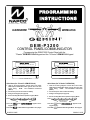
Programming the GEM-P3200 Control Panel with the
"Classic" GEM-RP1CAe2 Keypad and the "K Series" GEM-K1CA Keypad
GEMINI
GEMINI
SYSTEM READY
01/01/06
12:00 AM
SYSTEM READY
01/01/06
12:00 AM
ED
ARM
T
ST A
US
A
1
2
3
D
NEXT/YES
E
PRIOR/NO
F
B
4
5
6
C
7
8
9 0 G
AREA
C O M P UT E R I ZE D S E C U R I T Y SY S T E M
"Classic" GEM-RP1CAe2
ARM
ED
T
ST A
US
U
NEXT/YES
P
R
1
2
3
B
4
5
6
C
7
8
9 0 G
PRIOR/NO
Q
AREA
C O M P UT E R I ZE D S E C U R I T Y S Y S T E M
"K Series" GEM-K1CA
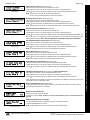
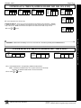
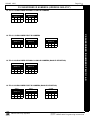
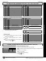
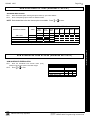
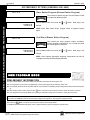
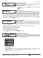
Quick Start (for "Classic" GEM-RP1CAe2)
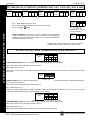
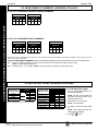
Quick Start (for "K-Series" GEM-K1CA)
1. Refer to the wiring diagram, connect Siren, Aux. Power,
PGM Output, Remote Bus, Earth ground, Zone and Telephone wiring.
NOTE:
See Installation Instructions
(WI817).
1. Refer to the wiring diagram, connect Siren, Aux. Power,
PGM Output, Remote Bus, Earth ground, Zone and Telephone wiring.
NOTE:
See Installation Instructions
(WI817).
2. Connect AC power first and then the battery.
2. Connect AC power first and then the battery.
3. Configure the keypad (see page 55).
3. Configure the keypad (see page 55).
4. Access the Easy Menu Driven (Dealer Program) Mode:
4. Access the Easy Menu Driven (Dealer Program) Mode:
Press EEEEEEA
Press EEEEEER
Master Security Code
(on microshield)
Master Security Code
(on microshield)
Press NO (g) until “ACTIVATE PROGRAM Y/N” appears on the
keypad display.
Press NO (Q) until “ACTIVATE PROGRAM Y/N” appears on the
keypad display.
Press YES (F) to Enter Dealer Program Mode. Go to page 5.
Press YES (P) to Enter Dealer Program Mode. Go to page 5.
© NAPCO 2005
WI818G 10/05
THIS MANUAL INCLUDES FEATURES WHICH ARE ONLY AVAILABLE IN CONTROL PANEL FIRMWARE
VERSION 50 OR LATER.
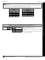
IMPORTANT NOTE
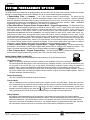
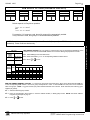
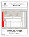
This manual supports the keypad programming of the GEM-P3200 control panel with the NAPCO "classic" GEMRP1CAe2 keypad as well as the GEM-K1CA "K Series" keypad. The new "K Series" GEM-K1CA model offers the new
STAY and AWAY buttons with simplified functionality, along with the new MENU and ENTER buttons. Note: While the
instructions in this manual are depicted using the GEM-K1CA keypad, the manual applies to both the "classic" and the
"K Series" keypads.
Program Mode is the same for both keypads--only the button names have changed, as follows:
• The A button and the R button operate identically (in Program Mode) for both keypads.
• The
D button and the U button operate identically (in Program Mode) for both keypads.
button and the
button operate identically (in Program Mode) for both keypads. The words
• The
"NEXT/YES button" are used in this manual.
button and the
button operate identically (in Program Mode) for both keypads. The words
• The
"PRIOR/NO button" are used in this manual.
For consistency, it is recommended that all keypads either be all "classic" or all "K Series"--both keypad
types should not be used in one alarm system.
CHANGES FROM PREVIOUS EDITION
The following changes have been made to this manual (WI818G) since the previous edition (WI818F).
New addresses added to accommodate the GEM-ACM1D / GEM-2D Access Control Accessories, as follows:
•
•
•
•
•
•
•
•
•
•
Enable ACM Access
ACM Zone Options
ACM Global Flags
ACM Timeouts
ACM Door Area Options
ACM Scheduled Free Access
Enable Panel Options
Emergency Free Access
Keypad Home Area / ACM Door #1 Area (Hex)
Addition to the Easy Program Menu instructions, "Enter Proximity Card Users".
Existing addresses were changed and new addresses were added to accommodate the NAPCO NetLink™ NL-Mod device, as follows:
•
•
•
•
•
For each telephone number desired, enable "Report to TCP/IP Receiver or AES" for Telco 1, Telco 2 and Telco 3.
Enable "Callback Telephone No. Select". Enter either "1" for Callback Telephone Number 1 or "2" for Callback Telephone Number 2.
Enable "Handshake for Local Telemetry"
Enable "TCP/IP Communications"
Enable "TCP/IP Panel/Site Initiated Functions"
NAPCO Security Group, Inc.,
333 Bayview Avenue, Amityville, New York 11701
For Sales and Repairs, call toll free: (800) 645-9445
For direct line to Technical Service, call toll free: (800) 645-9440
Internet: http://www.napcosecurity.com
Page 3
WI818G 10/05
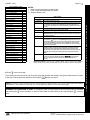
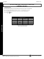
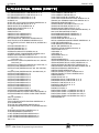
TABLE OF CONTENTS
IMPORTANT NOTE ...................................................... 2
CHANGES FROM PREVIOUS EDITION ..................... 2
SYSTEM PROGRAMMING OPTIONS......................... 4
Introduction ............................................................... 4
Downloading from a Computer ................................. 4
EASY MENU DRIVEN PROGRAM MODE .................. 5
Dealer Program - Preliminary Information ................ 5
Accessing Dealer Program Mode............................. 5
Customizing a Default Program................................ 5
GEM-RP1CAe2/GEM-K1CA Keypad Easy Program
Menu ......................................................................... 6
DIRECT ADDRESS PROGRAM MODE .................... 15
Direct Address Overview ........................................ 15
Address Mode Displays .......................................... 15
Binary (Bit) Format Example .............................. 15
Decimal Format Example ................................... 16
Hexadecimal Format Example ........................... 17
Programming Conventions Used in this Manual .... 18
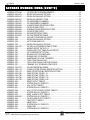
PROGRAMMING OPTIONS & WORKSHEETS........ 19
SYSTEM DELAYS & TIMEOUTS (ADDRESS 0000-0002, 2402, 2406, 2414 &
3902)............................................................................................19
SYSTEM DELAYS & TIMEOUTS (ADDRESS 2407, 2408 & 4088) ......................19
SYSTEM DELAYS & TIMEOUTS (ADDRESS 2400, 2401, 2403-2405, 4082 &
4083)............................................................................................20
KEYPAD SYSTEM CODES (ADDRESS 0490-0495 & 0500-0502).......................20
CS RECEIVER FORMAT OPTIONS (ADDRESS 0520, 0521, 0525, 0526, 0550,
0551, 0575 & 0576)....................................................................21
CS RECEIVER TELEPHONE NUMBERS (ADDRESS 0527-0546, 0552-0571,
0577-0596) ..................................................................................22
DOWNLOAD/CALLBACK OPTIONS (ADDRESS 4089, 0600-0619, 0625-0647,
1022 & 1023) ..............................................................................22
CS SUBSCRIBER ID NUMBERS (ADDRESS 0650-0787) ....................................23
CS SUBSCRIBER ID NUMBERS (ADDRESS 0790-0857) ....................................24
CS REPORTING CODES (ADDRESS 0859-0883) .................................................24
CS REPORTING CODES (ADDRESS 0870-0904) .................................................25
CS AREA & SYSTEM REPORTING OPTIONS (ADDRESS 1024-1027).............25
CS ZONE REPORTING CODES (ADDRESS 0910-0957) .....................................26
CS USER REPORTING CODES (ADDRESS 1030-1074) .....................................27
GLOBAL SYSTEM TROUBLE REPORTING OPTIONS (ADDRESS 1082-1116)28
AREA SYSTEM TROUBLE REPORTING OPTIONS (ADDRESS 1120-1137) ...29
ZONE OPTIONS / ZONES 1-16 (ADDRESS 1200-1386) .......................................30
ZONE OPTIONS / ZONES 17-32 (ADDRESS 1402-1586).....................................31
ZONE OPTIONS / ZONES 33-48 (ADDRESS 1602-1786).....................................32
SYSTEM OPTIONS (ADDRESS 2415-2419) ...........................................................34
SYSTEM OPTIONS (ADDRESS 2420-2422, 3874, 3905, 3880-3881) .................35
ALARM/TROUBLE REPORTING CODES (ADDRESS 3880-3881) .....................35
SYSTEM OPTIONS (ADDRESS 3882-3901, 3903-3905 & 4084) .........................36
KEYPAD OPTIONS (ADDRESS 2425-2446) ...........................................................37
ACM ZONE OPTIONS (ADDRESS 2740-2769).......................................................38
ACM GLOBAL FLAGS (ADDRESS 2780) ................................................................38
ACM TIMEOUTS (ADDRESS 2782-2783) ................................................................38
ACM DOOR AREA OPTIONS (ADDRESS 2784-2787) ..........................................39
ACM SCHEDULED FREE ACCESS (ADDRESS 4072-4075) ...............................39
KEYPAD HOME AREA / ACM DOOR #1 AREA (HEX) (ADDRESS 2425-2431) 40
SYSTEM OPTIONS (ADDRESS 2423) .....................................................................41
EMERGENCY FREE ACCESS (ADDRESS 4080)..................................................41
USER AREA OPTIONS (ADDRESS 2455-2502).....................................................42
EZM GROUP OPTIONS (ADDRESS 2555-2576)....................................................43
AREA ARMING OPTIONS (ADDRESS 2650-2651)................................................44
REMOTE ACCESS LOGGING (ADDRESS 3184) ..................................................44
AREA OUTPUT CONTROL OPTIONS (ADDRESS 2700-2739) ...........................45
RF RECEIVERS & SUPERVISORY TIMER OPTIONS (ADDRESS 3776 & 37603775)............................................................................................46
EXTERNAL RELAY CONTROL / RELAYS 1-24 (ADDRESS 3778-3801 & 28002895)............................................................................................47
NUMBER OF RELAY BOARD MODULES (ADDRESS 3777)...............................51
SYSTEM RESET OPTIONS (ADDRESS 4091-4093) .............................................52
USER PROGRAM MODE .......................................... 52
Preliminary Information........................................... 52
Accessing User Program Mode ............................. 53
User Codes ............................................................ 53
Zone Descriptions .................................................. 54
KEYPAD CONFIGURATION MODE ......................... 55
Keypad Installation ................................................. 55
Configuring the Keypads ........................................ 55
ALPHABETICAL INDEX ............................................ 57
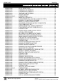
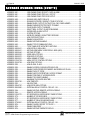
ADDRESS NUMBER INDEX ..................................... 61
GEM-P3200 WIRING DIAGRAM ............................... 68
Refer to accompanying GEM-P3200 Installation Instructions (WI817) for installation information.
L
NAPCO Security Systems
X
GEM-P3200 Programming Instructions
Page 4
WI818G 10/05
SYSTEM PROGRAMMING OPTIONS
INTRODUCTION
The GEM-P3200 control panel may be programmed by various means, each of which will be covered in detail in the sections
that follow. Keypad displays shown are for a GEM-K1CA (v.8), the recommended keypad for programming.
Downloading From a Computer.
This is the preferred method of programming. The panel may be
downloaded from (or uploaded to) an IBM PC-compatible computer, either locally or remotely. Napco's PCD3000
and PCD Windows Quickloader software feature context-sensitive help screens as well as an error-checking utility
that prevents programming of incompatible or conflicting data to ensure proper panel operation. Note: Unattended
downloading from a computer is not allowed for Fire Alarm or UL installations.
Easy Menu-Driven Program (Dealer Program) Mode - Keypad Programming. The Easy Menu-Driven
Program Mode allows keypad programming of number of zones in Area 1 and 2, number of fire zones (both 4-wire
and 2-wire), local or Central Station reporting, number of exit/entry zones, number of interior zones, number of 24
hour zones, number of chime zones, Chime 2 zones, Exit/Entry2 zones, 50ms loop response zones (Note: 750mS is
required for Loop Response time in UL installations), aux output activated on alarm zones, sensor watch zones, keypad sounder on alarm zones, auto bypass re-entry zones, EOLR zones, number of keypads in Area 1 and 2, Central
Station telephone number, Central Station account number, Central Station receiver format, User Codes, RF transmitter points, RF keyfob transmitters, zone descriptions, date/time, dealer code, Telco line fault test, Burg output chirp
on keyfob, keypad time/date display, enable CP-01 programming, and clear dealer program/cold start. For new panels, a custom default program may be created at the keypad. A menu-driven utility prompts the installer to configure
the system. Further detailed customization is accomplished in the Direct Address Program Mode.
Direct Address (Dealer Program) Program Mode - Keypad Programming. The Direct Address Program Mode is an extension of the Dealer Program Mode wherein data is entered at the keypad by location. This
mode is accessed from the Easy Menu Driven Program Mode by pressing the C button at any time.
User Program Mode - Keypad Programming. The User Program Mode is intended for authorized users
and is limited to keypad programming of User Codes, Time, Date and Zone Descriptions.
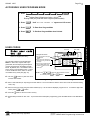
DOWNLOADING FROM A COMPUTER
The control-panel program may be downloaded from the computer by any of the following methods.
Local Downloading
(Note: This procedure should be used after installation, after peripheral devices are connected).
For direct high-speed data transfer to the control panel from a desktop computer, connect the download jack (JP2)
on the panel to the LOCAL jack (J3) on the Napco PCI2000/3000 computer interface using the supplied 6conductor cable. (Refer to PCI2000/3000 Installation Instructions WI443 for wiring diagram and procedures).
Similarly, a high-speed local download may be made in the field using a notebook or laptop computer. Connect
JP2 on the control panel to a Napco PCI-MINI computer interface using the 6-conductor cable supplied. (Refer to
PCI-MINI Installation Instructions WI767).
Remote Downloading
(Also see PCI2000/3000 Installation Instructions WI443).
Function Mode
Start by establishing a telco connection between the computer operator and the installer. During this procedure,
voice contact will be lost, therefore both the installer and the computer operator should be familiar with the operation. When a steady high-pitched tone is heard at the site phone, access the “ACTIVATE DOWNLOAD” Function (see
Keypad Programming Modes), then press the J or U button or the NEXT/YES button; the site phone will go dead.
Hang up the phone and wait for a call from the central station confirming a successful download.
Callback Method
An installed, unattended panel may be programmed or reprogrammed remotely using the Callback-Method
Download feature of the PCD-Windows Quickloader software. Remote downloading requires a modem compatible
with the PCI2000/3000. Upon answering the call from the computer, the panel will verify the Download Security
Code and, if confirmed, will establish a connection. If a Callback Number is programmed into the panel, the panel
will automatically disconnect and call the computer at this number before establishing a connection.
X
GEM-P3200 Programming Instructions
L
NAPCO Security Systems
Page 5
WI818G 10/05
EASY MENU DRIVEN PROGRAM MODE
DEALER PROGRAM - PRELIMINARY INFORMATION
Only Keypad #1 may be used for both dealer and user programming, however this keypad may be located in any area.
The Master Security Code is printed on the panel’s microprocessor can. Use this code to enter the Dealer Program Mode
to program a custom Dealer Security Code. Record the number, then remove the code label to prevent unauthorized
access to the panel. If you forget your Dealer Security Code, use the Master Security Code to enter programming.
After entering codes or data, press the save U button. Data will not be stored into memory unless it is pressed.
If the keypad is in the Program Mode and no activity is detected for longer than 4 minutes, a steady tone will sound.
Silence the sounder by pressing the G button to continue, or by pressing the C button to exit.
A panel that has been COLD STARTED (Address Location 4093) performs identically to a new panel.
If a GEM-RP2ASe2/GEM-K2AS (Version 6) is used, configure address jumpers as Keypad #1 (see WI1184).
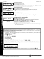
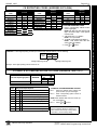
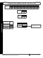
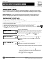
ACCESSING DEALER PROGRAM MODE
1. Press EEEEEE R
GEM-P3200
R
Master Security Code
(on microshield)
CONTROL
COMMUNCIATOR
MASTER SECURITY CODE
#-#-#-#-#-#
2. Press Q Until “ACTIVATE PROGRAM Y/N” appears on the keypad display.
3. Press P To Enter Dealer Program Mode.
4. Press CC To Exit Dealer Program Mode when finished.
CUSTOMIZING A DEFAULT PROGRAM
For new panels, you can design a default program that will best suit your application. Using this procedure, you will configure the panel for:
•
•
•
•
•
•
•
•
•
•
•
•
Total Number of Zones in Area 1
Total Number of Zones in Area 2
Fire Zones in Area 1
2-Wire Fire Zones in Area 1
Report All Zones to Central
Exit/Entry Zones in Area 1
Interior Zones in Area 1
24 Hour Zones in Area 1
Chime Zones in Area 1
Chime 2 Zones in Area 1
Exit/Entry2 Zones in Area 1
50mS Loop Response Zones (Note:
750mS is
required for Loop Response time in UL installations).
•
•
•
•
•
•
•
•
•
•
•
•
Aux Output Activated on Alarm Zones
Sensor Watch Zones
Keypad Sounder on Alarm Zones
Auto Bypass re-entry Zones
Enable no EOLR Zones
Enable Telco Line Fault Test
Enable Burg Output Chirp on Keyfob
Enable SIA CP-01 Features
Number of Keypads in Area 1
Number of Keypads in Area 2
Central Station Receiver 1 Tel. Number
Central Station Receiver 1 Account Number
•
•
•
•
•
•
•
•
•
•
•
Central Station Receiver 1 Format
Enter User Codes
RF Transmitter Points
Quick Method (Enroll Method)
KeyFob Transmitters (as Arm/Disarm & Control
Devices)
KeyFob Transmitters (as Zone Input Devices)
Enter Zone Descriptions
Enter Date
Enter Time
Dealer Code
Exit Dealer Program Mode
This procedure will automatically set up system keypads, EZMs, wireless transmitters, etc. After your basic default program has been
loaded, you may alter it as necessary in the Direct Address Program Mode.
NEW PANELS: The custom default program may be created for new panels only. Once the panel has been programmed by any
means, the number of areas, number of zones, fire zones, entry/exit zones and interior zones will be suppressed and cannot be
changed. Should it be necessary to create a new custom default program, (a) from the Dealer Program Mode, press the C
button to enter the Direct Address Program Mode; (b) access Location 4091 (Clear Program); (c) press the U button and start over.
L
NAPCO Security Systems
X
GEM-P3200 Programming Instructions
EASY MENU DRIVEN PROGRAM MODE
KEYPAD #1: For ease of programming, it is recommended that a GEM-K1CA (Version 8) be used as Keypad #1.
(Regardless of which keypad is selected, all new keypads are configured as Keypad #1 out of the box).
Page 6
WI818G 10/05
GEM-RP1CAe2/GEM-K1CA Keypad Easy Program Menu
To create a custom program using the GEM-RP1CAe2/GEM-K1CA keypad, simply answer the following questions and re-
cord your information on the Easy Menu Programming Worksheet. In each of the following steps, press R to set cursor,
the NEXT/YES button to go forwards, the PRIOR/NO button to go backwards, U to save and C twice to exit at any time.
#of Zns in Area1
Enter # Zones XX
GEM-RP1CAE2/GEM-K1CA KEYPAD EASY PROGRAM MENU
(Direct Entry)
Total Number of Zones in Area 1 (New Program Only)
• Enter the total number of zones to be programmed for Area 1.
• Valid entries are from 08 to 48. Directly enter the total number of zones, including leading zeros.
• The system is based on groups of 4 zones each (after the first 8 zones), and will automatically round up to
the next group of 4. For example, if you enter 18, it will automatically convert this to 20 zones. Press U to
save. Press the NEXT/YES button to proceed.
#of Zns in Area2
Enter # Zones XX
(Direct Entry)
Total Number of Zones in Area 2 (New Program Only)
• Enter the total number of zones to be programmed for Area 2.
• Valid entries are from 00 to 48. Directly enter the total number of zones, including leading zeros.
• The system is based on groups of 4 zones each (after the first 8 zones), and will automatically round up to
the next group of 4. For example, if you enter 18, it will automatically convert this to 20 zones. Press U to
save. Press the NEXT/YES button to proceed.
Fire Zones
Enter Zone # °°
(Direct Entry)
Fire Zones in Area 1 (New Program Only)
• Enter the zone number of any Fire Zones (including 2-wire, 4-wire or wireless).
• Valid entries are from 01 to 48.
• Directly enter each zone number, including leading zeros, and press U to save, and then repeat for any
additional zone(s). Press the NEXT/YES button to proceed.
2-Wire Fire Zones in Area 1 (New Program Only)
2-Wire Fire Zns
Enter Zone # ° °
(Direct Entry)
• Enter the zone number of any Fire Zone (from previous question) to be used with 2-wire smoke detectors.
• Valid entries are 07 and 08. Directly enter each zone number, including leading zeros.
• Press U to save, and repeat for any additional zone(s); press NEXT to proceed.
NOTE: Only zones which have been designated as Fire Zones can be programmed as 2 Wire Fire zones.
JP3 must be set to “2-WF” position for 2-wire fire for zones 7-8. (refer to Installation Instructions).
Local or Central Station Reporting System (New Program Only)
Report All Zones
To Central? Y/N
Press the NEXT/YES button for all zones to report; press the PRIOR/NO button for local system.
(Press YES or NO)
Exit/Entry Zones
Enter Zone # XX
(Direct Entry)
Exit/Entry Zones in Area 1 (New Program Only)
• Enter the zone numbers of zones to be used as Exit/Entry zones.
• Valid entries are from 01 to 48. Directly enter each zone number, including leading zeros.
• Press U to save and repeat for any additional zone(s); press the NEXT/YES button to proceed.
NOTE: Entry Delay Time of 30 seconds and Exit Delay Time of 60 seconds will automatically be programmed.
Interior Zones
Enter Zone # XX
(Direct Entry)
Interior Zones in Area 1 (New Program Only)
• Enter the zone numbers to be used as Interior Zones.
• Valid entries are from 01 to 48. Directly enter each zone number, including leading zeros.
• Press U to save and then repeat for any additional zone(s).
• Press the NEXT/YES button to proceed.
• All Interior zones will also be automatically programmed as “Exit/Entry Follower” and as "Power Up Delay" zones.
24 Hour Zones
Enter Zone # °°
(Direct Entry)
24 Hour Zones in Area 1 (New Program Only)
• Enter the zone numbers of zones to be used as 24 Hour zones.
• Valid entries are from 01 to 48. Directly enter each zone number, including leading zeros.
• Press U to save and repeat for any additional zone(s); press the NEXT/YES button to proceed.
NOTE: 24 Hour Zones will automatically be programmed as audible (Burg Output).
Chime Zones
Enter Zone #
(Direct Entry)
Chime Zones in Area 1 (New Program Only)
°°
• Enter the zone numbers which are to be used as Chime Zones.
• Valid entries are from 01 to 48. Directly enter each zone number, including leading zeros.
• Press U to save and then repeat for any additional zone(s), press the NEXT/YES button to proceed.
NOTE: A chime time of 2 seconds will be automatically programmed.
X
GEM-P3200 Programming Instructions
L
NAPCO Security Systems
Page 7
WI818G 10/05
Chime 2 Zones
Enter Zone # °°
(Direct Entry)
Chime 2 Zones in Area 1 (New Program Only)
• Enter the zone numbers which are to be used as Chime 2 Zones.
• Valid entries are from 01 to 48. Directly enter each zone number, including leading zeros.
• Press U to save and then repeat for any additional zone(s), Press the NEXT/YES button to proceed.
NOTE: A chime time of 2 seconds will be automatically programmed.
Chime 2 zones give a distinct pulsating tone when zone is faulted.
Exit/Entry2 Zones
Enter Zone # °°
• Enter the zone numbers of zones to be used as Exit/Entry zones.
• Valid entries are from 01 to 48. Directly enter each zone number, including leading zeros.
• Press U to save and repeat for any additional zone(s); press the NEXT/YES button to proceed.
NOTE: An Entry Delay Time of 30 sec. and an Exit Delay Time of 60 sec. will automatically be programmed.
50mS Loop Zones
Enter Zone # °°
(Direct Entry)
50 mS Loop Response Zones (New Program Only)
• Enter the zone numbers of zones to have a 50mS loop response.
• Valid entries are from 01 to 08. Directly enter each zone number, including leading zeros.
• Press U to save and then repeat for any additional zone(s), Press the NEXT/YES button to proceed. Note: Only
panel zones 01-08 can be programmed for Quick Loop Response. All other zones can be programmed via their
respective EZM's (hardwire). Note: 750mS is required for Loop Response time in UL installations.
Aux Output Zones
Enter Zone # ° °
(Direct Entry)
Aux Output Activated on Alarm Zones (New Program Only)
• Enter the zone numbers of zones to activate the Aux Output upon alarm.
• Valid entries are from 01 to 48. Directly enter each zone number, including leading zeros.
• Press U to save and then repeat for any additional zone(s), Press the NEXT/YES button to proceed.
NOTE: An Aux Output Timeout of 15 minutes will automatically be programmed.
Sensor Watch Zns
Enter Zone # ° °
(Direct Entry)
Sensor Watch Zones (New Program Only)
• Enter the zone numbers of zones to be Sensor Watch zones.
• Valid entries are from 01 to 48. Directly enter each zone number, including leading zeros.
• Press U to save and then repeat for any additional zone(s), Press the NEXT/YES button to proceed.
NOTE: A Sensor Watch Time of 24 hours will automatically be programmed.
KP Sndr Alrm Zns
Enter Zone # ° °
(Direct Entry)
Auto Byp REnt Zn
Enter Zone # ° °
(Direct Entry)
Keypad Sounder On Alarm Zones (New Program Only)
• Enter the zone numbers of all zones to activate the Keypad Sounder upon alarm.
• Valid entries are from 01 to 48. Directly enter each zone number, including leading zeros.
• Press U to save and then repeat for any additional zone(s), Press the NEXT/YES button to proceed.
Auto Bypass Re-entry Zones (New Program Only) (Not evaluated by UL)
• Enter the zone numbers of zones to be Auto Bypass Re-entry zones.
• Valid entries are from 01 to 48. Directly enter each zone number, including leading zeros.
• Press U to save and then repeat for any additional zone(s), Press the NEXT/YES button to proceed.
• Auto Bypass Re-entry Zones allow the system to be armed with the zone faulted but come back into the system
(armed) when the zone is subsequently closed.
Enable No EOLR
Zones
Y/N
Enable No EOLR Zones (New Program Only)
• Press YES to program all zones except 24 Hr & fire zones for No End Of Line Resistor. Press NO to continue.
• Do not program this feature for UL Installations.
(Press YES or NO)
Enable Telco Line Fault Test?
Enable Telco
Line Test?
Y/N
(Press YES or NO)
• Press YES to enable Telco Line Fault Test.
• Press NO to continue. NOTE: If enabled, a Telco Line Fault Test Delay of 60 sec. will automatically be programmed.
Enable Burg Output Chirp on KeyFob?
Enable Burg Out
Chirp?
Y/N
(Press YES or NO)
L
• Press the NEXT/YES button to enable Burg Output Chirp on KeyFob Arm / Disarm.
• Press the PRIOR/NO button to continue.
NOTE: The Burg Output will chirp once on Keyfob Arm and twice on Keyfob Disarm.
NAPCO Security Systems
X
GEM-P3200 Programming Instructions
GEM-RP1CAE2/GEM-K1CA KEYPAD EASY PROGRAM MENU
(Direct Entry)
Exit/Entry2 Zones in Area 1 (New Program Only)
Page 8
WI818G 10/05
Enable SIA CP-01 Features?
Enable SIA CP-01?
Y/N
(Press YES or NO)
# Area 1 Keypads
Enter # KPs
01
GEM-RP1CAE2/GEM-K1CA KEYPAD EASY PROGRAM MENU
(Direct Entry)
# Area 2 Keypads
Enter # KPs
00
(Direct Entry)
• Press the NEXT/YES button to enable.
• Press the PRIOR/NO button to continue.
The SIA CP-01 Features are designed to reduce the incidence of false alarms. NOTE:
unless reporting, otherwise system trouble Fail to Communicate may occur.
Do not enable
Number of Keypads in Area 1
• Enter the total number of Keypads to be installed in Area 1.
• Valid entries are from 01 to 07. Directly enter the number of keypads, including leading zeros.
Press U to save. Press the NEXT/YES button to proceed.
Number of Keypads in Area 2
• Enter the total number of Keypads to be installed in Area 2.
• Valid entries are from 00 to 07. Directly enter the number of keypads, including leading zeros.
Press U to save. Press the NEXT/YES button to proceed. NOTE: Area 2 keypads must have zones in
Area 2, otherwise the keypad will indicate "Out Of System".
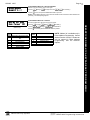
Central Station Receiver 1 Telephone Number
Central Phone #
(Direct Entry)
• Enter telephone number of up to 16 digits.
• Press 1 through 9 for digits 1–9; G 0 for a zero and 0 for a blank (•).
• Press G 1 through G 5 for letters B–F, respectively.
• Pre-Dial Delay = “D” (G 4); Dial-Tone Detection = “E” (G 5).
• Press U to save and press the NEXT/YES button to proceed.
NOTE: Central Station Receiver 2 and 3 Telephone Numbers must be entered in Direct Address Programming. See CS Receiver Options.
Easy Programming of Auto download ID #'s and PC Preset Callback Numbers (GEM-RP1CAe2 or GEM-K1CA
keypads only) from the Central Station Telephone number.
For unattended PC Preset downloading, it is now possible to set the Auto download ID #’s and PC Preset Callback
from the Keypad Easy Program Mode.
• At the field for CENTRAL PHONE #, program an "F" followed by the Auto Download ID # (2 digits) and then the
Callback Telco # (up to 13 digits).
• Press D or U to save.
•
•
•
•
•
Exit Program Mode (CC)
Enter Master Code
Press A or R
Go to Function "ACTIVATE DOWNLOAD Y/N" and press YES (E or P).
The panel will automatically call the PC Preset computer and download the program on the specified Auto
Download line # of PC Preset. Example: Program an Auto download ID # of 07 and a PC Preset Callback # of
1-516-842-9400
CENTRAL PHONE #
F0715168429400
• Go to Central Phone # input screen and press: [*] [5] [0] [7] [1] [5] [1] [6] [8] [4] [2] [9] [4] [0] [0] D (or U).
X
GEM-P3200 Programming Instructions
L
NAPCO Security Systems
Page 9
WI818G 10/05
Central Station Receiver 1 Account Number
Central Station
Account # (____)
(Direct Entry)
• Enter an account number of up to four digits.
• Press 0 through 9 for digits 0–9, and G 0 for a blank (•).
• Press U to save and press the NEXT/YES button to proceed.
NOTE: Central Station Receiver 2 and 3 Account Numbers must be entered in Direct Address Programming. See CS Reporting Options.
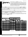
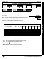
Central Station Receiver 1 Format
See WI for Info
Rcvr Format (0)
DATA
ENTRY
blank(•)
• Press U to save and press the NEXT/YES button to proceed.
CS RECEIVER 1 FORMAT
DATA
ENTRY
Ademco Slow, Silent Knight Slow
9
FBI 4/3/1
Sescoa, Vertex, DCI, Franklin
Fast
Radionics Fast
0
Radionics Modem 2
B
SIA
3
Silent Knight Fast
C
Ademco Point ID
4
Radionics, DCI, Franklin Slow
D
Ademco Express
5
Universal High Speed
E
Pager
8
Radionics BFSK
1
2
L
NAPCO Security Systems
CS RECEIVER 1 FORMAT
NOTE: Modem IIe is available only in
Direct Address Programming. Central
Station Receiver 2 and 3 Formats can
only be entered in Direct Address
Programming. See CS Receiver
Options.
X
GEM-P3200 Programming Instructions
GEM-RP1CAE2/GEM-K1CA KEYPAD EASY PROGRAM MENU
(Direct Entry)
• From the table at the right enter the receiver format.
• Press 0 through 9, and G0 for blank (•).
• Press G1 through G4 for letters B–E.
Page 10
WI818G 10/05
Enter User Codes (Press the R button to set cursor.)
Enter up to 48 User Codes with User Options, Authority Level and Access
Control Options (if necessary) for each code. Refer to the tables below and on
the next page for available data entries for User Options, Authority Level and
Access Control Options. Note: All 48 Users must be assigned to areas in “User
Area Options” (Address 2455-2502) in Direct Address Programming. By default, only User 1 is enabled in Area 1 and Area 2. Users 2 - 8 are enabled in
Area 1 and users 9 - 16 are enabled in Area 2.
Enter user code
001 123
-E3User#
User Code
GEM-RP1CAE2/GEM-K1CA KEYPAD EASY PROGRAM MENU
Press the R button
to set the cursor to the User Code. Use the number buttons 1 through 9 to enter
a code from 3 to 6 digits. Enter up to 6 digits in the first six boxes from left to right for each user code. Valid entries
are: 0-9. Note: Press the 0 button for a zero. No blank spaces in between; leave blank (•) any trailing boxes. If
an “Ambush Code” (Address 0495) is entered, do not program the first two digits of ANY User Code as the same
digits entered for the “Ambush Code”.
If the programmed code is less than 6 digits, press the R button to set the cursor to the OPTION/LEVEL.
Refer to the tables below for the available User Option and User Level data entries. Enter the user options data in
the left digit. Enter the level data (with arming options, if any, added) in the right digit. Note: For entries greater than
9, press the G1 buttons through the G5 buttons for B through F, respectively.
For Keypad Access Control, press the R button once again to program applicable keypads. Refer to the tables
below, use the number buttons to enter the data for Keypad 1–4 in the right digit; and the data for Keypad 5–7 data in
the left digit. (Press the 0 buttons for blank).
Example: Enter a code of “123456” as
“123456” (from left to right).
USER OPTIONS
DATA BLOCKED
USER
BYPASS
ENTRIES VIEW
PROGRAM
3
7
Y
blank (•)
LEVEL 2
ARM/DISARM
1
Y
3
LEVEL 3
ARM/DISARM
2
Y
4
NONE
ARM ONLY
3
Y
5
LEVEL 1
ARM ONLY
4
Y
6
LEVEL 2
ARM ONLY
5
Y
Y
7
LEVEL 3
ARM ONLY
6
Y
Y
8
NONE
SERVICE
7
Y
9
LEVEL 1
SERVICE
8
Y
0
LEVEL 2
SERVICE
9
Y
Y
B
LEVEL 3
SERVICE
0
Y
Y
C*
NONE
AMBUSH
B
Y
Y
D*
LEVEL 1
AMBUSH
C
Y
Y
E*
LEVEL 2
AMBUSH
D
Y
Y
Y
F*
LEVEL 3
AMBUSH
E
Y
Y
Y
Y
0
B
Y
C
D
Y
E
F
Y
Note: “Y” indicates option is enabled.
X
blank (•)
ARM/DISARM
2
8
9
DATA
K.P. 1 K.P. 2 K.P. 3 K.P. 4
ENTRIES
ARM/DISARM
Y
6
ACCESS CONTROL KEYPADS
DATA
K.P. 5 K.P. 6 K.P. 7
ENTRIES
NONE
4
5
ACCESS CONTROL KEYPADS
LEVEL 1
Y
Y
CODE
TYPE
ACCESS CONTROL
KEYPADS
1
DISABLED
2
DATA
AUTHORITY
ENTRIES
LEVEL
USER OPTIONS
USER
USER
OPTION LEVEL
blank (•)
blank (•)
1
OVERVIEW
USER CODE
(UP TO 6 DIGITS)
*Note: These entries are only
available when address 3905
option 8 is enabled.
GEM-P3200 Programming Instructions
F
NONE
Y
Y
1
Y
2
Y
3
Y
4
Y
5
Y
Y
6
Y
Y
7
Y
Y
NONE
Y
Y
Y
Y
Y
Y
Y
Y
Y
Y
Y
Y
8
Y
Y
9
Y
0
Y
B
Y
C
Y
D
Y
Y
E
Y
Y
F
Y
Y
Note: “Y” indicates option is enabled.
L
Y
Y
Y
Y
Y
Y
Y
Y
Y
Y
Y
Y
Y
Y
Y
Y
Y
Y
Y
Y
Note: “Y” indicates option is enabled.
NAPCO Security Systems
Page 11
WI818G 10/05
USER AUTHORITY LEVEL
KEYPAD DISPLAY FUNCTION MENU
FUNCTION
DISPLAY ZN FAULTS
LEVEL*
1
NOTES:
* Minimum Level required to access function
** Level-3 Code with appropriate user option
*** Requires Dealer Code
DISPLAY ZN BYPASSED
1
DISPLAY ZN DIRECTORY
1
ACTIVATE BELL TEST
1
DISPLAY PHONE #’S
1
DISPLAY SYS TRBL
1
DISPLAY FIRE ALARM
1
Disabled
DISPLAY FIRE TRBL
1
Blocked View
DISPLAY OP/CL
3
3**
ACTIVATE CHIME
1
ACTIVATE WATCH
2
RESET SYSTEM TRBL
3
RESET SENSOR MSG
3
START EXIT TIME
User Program
Bypass
Overview
1
FAULT FIND
***
Arm Only
ACTIVATE LOCATE
***
Service
EZM ZONE FIND
***
ACTIVATE DIALER TEST
3
DISPLAY ALARM LOG
3
DISPLAY TOTAL LOG
3
DISPLAY FIRE LOG
3
DISPLAY OP/CL LOG
3
DISPLAY SYSTEM LOG
3
AUTOARM IN 1-4HRS
2
DISPLAY AUTOARM SCHD
ACTIVATE PROGRAM
3
3**
ACTIVATE DOWNLOAD
3
DISPLY RF XMITTER STAT
1
RELAY CONTROL
1
Ambush
Access
EXPLANATION
User Code not active in this area.
Allows User Code to block another code from being viewed by another user.
An unblocked code cannot view a blocked code, but a blocked code can
view all codes. The master user code and the dealer program code can view
all codes.
User Program Option is enabled for Keypad 1 only, wherever it is connected
(any area). If enabled, Level 3 must also be enabled.
Allows User Code to bypass zones.
This option, along with Level 3 Authorization, enables selection of
OVERVIEW mode at a keypad. This Mode provides a system status display
of all areas at a glance.
Prevents User Code from disarming this area.
A Service Code has restricted arm/disarm rights; if an area is armed with a
Service Code, a “5” appears on the GEM-RP1CAe2 keypad and the area can
be disarmed with any valid User Code, including a Service Code. If the area
is armed with OTHER than a Service Code, it CANNOT be disarmed with a
Service Code. This is typically used to allow tradesmen access to premises
under control of the owner.
There are two types of Ambush Codes: (1) A 2-digit code (prefix) that is entered
immediately prior to (and as part of) the regular User Code and (2) A separate
and unique User Code. Disarming with an Ambush Code will cause a silent
report to be sent to a central station. Thus, should a user be forced to disarm, he
can silently signal an emergency while appearing to be merely disarming the
system.
This is normally used to activate a door striker while an area is disarmed. A
code with the access option will not function as an arm/disarm code. When
the code is entered, the keypad will display “ENTER NOW” and the Brown
Wire on the keypad will become Active Low (Ground Potential) for 7
seconds.
Related User Options: “Ambush Code” (Address 0495), “Panel Access Code” (Address
0490), “Dealer Security Code” (Address 0500) & “User Area Options” (Address 2455-2502).
Press U to save each code.
To proceed to the next User Code, set the cursor to the User Number and change it using the number buttons. Program
a new User Code as previously described. Press NEXT P button to proceed.
Example: Program a code of “2222” for user 02, with User Option of “User Program”, User “Level 3” and Access Control Option
“Keypad No. 1”. Enter “2222” for a user code, “2 3” for user option and “blank(•) 1” for access control option.
CHANGING OR CANCELING A CODE: To change any code, merely program over the existing code as described
above and press U to save. Similarly, to cancel a code, blank out each number of the code and press U to save to
save.
L
NAPCO Security Systems
X
GEM-P3200 Programming Instructions
GEM-RP1CAE2/GEM-K1CA KEYPAD EASY PROGRAM MENU
ACTIVATE OVERVIEW
USER OPTIONS
OPTIONS
Page 12
WI818G 10/05
Enter Proximity Card Users (FOR ACM USE ONLY).
(Press the R button to set cursor). See WI1221 for more information.
Enter up to 48 Proximity Cards with User Options, Access Level and ACM
Area (if necessary) for each card. Refer to the tables below and to WI1221 for
more information.
Enter user code
001 123456- 6User#
User Code
GEM-RP1CAE2/GEM-K1CA KEYPAD EASY PROGRAM MENU
Press the R button to set the cursor to the User Code. Use the
number buttons 1 through 9 to enter a 6 digit code. Enter the digits in the first six boxes from left to right
for each user code. Valid entries are: 0-9. Note: Press the 0 button for a zero. No blank spaces in between;
leave blank (•) any trailing boxes.
Refer to the tables below and WI1221 for the available User Level data entries.
Enter the level data in the right
digit. Leave blank (•) in the left digit. Note: For entries greater than 9, press the G1 buttons through the
G5 buttons for B through F, respectively.
For ACM Area, enter data for Areas 1 or 2.
Example: Enter a code of “123456”
as “123456” (from left to right).
See table below.
USER CODE
(UP TO 6 DIGITS)
USER OPTIONS
USER
LEVEL
ACM AREA
ACM AREA
DATA
ENTRIES
DATA
ENTRIES
ACCESS
LEVEL
CODE
TYPE
blank (•)
0
NONE
1
1
NONE
2
2
NONE
4
0
ARM/DISARM
5
1
ARM/DISARM
6
2
ARM/DISARM
8
0
ARM ONLY
9
1
ARM ONLY
0
2
ARM ONLY
A1
blank (•)
1
NONE
Y
2
X
GEM-P3200 Programming Instructions
3
A2
Y
Y
Y
Note: “Y” indicates option is enabled.
L
NAPCO Security Systems
Page 13
WI818G 10/05
ZN#
XMIT#+CS P
Zn01- 000000:0-0
Zone #
Mapped to
Xmitter
ID
Check
Sum
Point
#
RF Transmitter Points (Press R to set cursor.)
For each transmitter enter: (For wireless systems only. Also see Quick Method, which follows)
• The zone number (01–48) to which the transmitter will be mapped.
• The 6-digit RF ID # and 1-digit checksum number printed on the transmitter and box,
• The point number (1–2); enter “9” for unsupervised (all points).
• Press U to save and NEXT/YES button to proceed when all transmitters have been entered.
NOTE: When programming the ID Code number, “0” through ”9” = 0 through 9; A = G0 ; B = G1 ; C =
Quick Method (Enroll Method). If a receiver is already installed in the panel, transmitter wireless points can be programmed automatically
(“enrolled”) using the following procedure. NOTE: The transmitter point will be enrolled only if the signal
ZN#
X M I T # + C S P strength is 3 or greater.
Z n 0 1 - 0 0 0 0 0 0 : 0 - 0 1. Enter the zone number to which the transmitter point will be mapped.
ZN#
XMIT#+CS P
ZN01- ENROLL:A--
2. Press B to enter the Enroll Mode. The red and green LEDs on the keypad will
flash and the window will display as shown at left.
3. Open the loop of the point that is to be programmed (GEM-TRANS2 only).
4. Install the transmitter battery. The keypad will beep to indicate that the point has been
successfully enrolled. Multi-point transmitters can be mapped to successive zones
simultaneously.
to Zone 6).
Example. A 2-point transmitter has the RF ID number 287613:1. Map point
5. Enter Zone “09”.
1 to Zone 6 and point 2 to Zone 9.
6. Close point-1 loop and open point-2 loop.
1. Enter the Enroll mode as described above.
7. Remove the transmitter battery, then re-install it. The keypad will beep
2. Enter Zone “06”.
once to indicate that one point has been programmed. (Transmitter
3. Open point-1 loop.
287613:1, point 2 is mapped to Zone 9).
4. Install the battery. The keypad will beep once to indicate that one point
has been programmed. (Transmitter 287613:1, point 1 will be mapped
KEYFOB ZONE ASSIGNMENT: Keyfobs can also be assigned to zones to allow multiple wireless panic buttons on one alarm system, each reporting to a central station, a pager or having a description on the keypad that describes the person holding the keyfob,
the location where the person holding the keyfob is stationed, or the special purpose of the keyfob button being depressed. See the
next page on Keyfob Transmitters as Zone Input Devices .
KF A XMIT#+CS OP
01-0 000000:0 00
KF
#
Area
Xmitter
ID
Check
Sum
Aux
1&2
Keyfob Transmitters as Arm/Disarm & Control Devices (Press R to set cursor).
Keyfobs can be programmed as “Arm/Disarm” devices using their On/Off buttons (refer to WI752).
For each Keyfob Transmitter, enter:
• The Keyfob Transmitter number (01–08).
•
•
•
•
•
•
The area number to which transmitter is assigned (0 to disable keyfob, 1 or 2).
The 6-digit RF ID # and 1-digit checksum number printed on the transmitter and box,
The Aux 1 Option (see keyfob aux 1 & aux 2 options).
The Aux 2 Option (see keyfob aux 1 & aux 2 options).
NOTE: Keyfobs 1-8 report openings and closings as Users 25-32.
Press U to save and NEXT/YES button to proceed when all keyfobs have been entered.
NOTE: When programming the ID Code number, “0” through ”9” = 0 through 9 ; A = G0 ; B = G1 ;
C = G2 ; D = G3 ; E = G4 and “F” = G5.
L
NAPCO Security Systems
X
GEM-P3200 Programming Instructions
GEM-RP1CAE2/GEM-K1CA KEYPAD EASY PROGRAM MENU
G2 ; D = G3 ; E = G4 and “F” = G5.
Page 14
WI818G 10/05
KeyFob Transmitters as Zone Input Devices
GEM-RP1CAE2/GEM-K1CA KEYPAD EASY PROGRAM MENU
(Refer to display above: press the PRIOR button to go backwards).
Each of the 4 keyfob buttons can be assigned to a zone. For example, On button = point 1; Off button = point
2; A1 = point 3; A2 = point 4. Up to 48 keyfobs (using 1 button) or 24 keyfobs (using 2 buttons) or 14 keyfobs
(using all 4 buttons) or any combination up to a maximum of 48 controlled zones can be assigned, providing
multiple wireless panic buttons on a system, each reporting to a Central Station or a pager and/or annunciating
on a keypad the keyfob zone number with a description. To assign a keyfob to a zone: program the keyfob as
you would a transmitter, entering the keyfob's ID code, check sum and point number at the appropriate zone.
The “Quick Method” is not allowed. The zone may be hardwired to an electrical sensor as well as assigned to
a keyfob (either one will activate the zone alarm output). NOTE: If assigning a keyfob to a zone, the “ON/OFF”
buttons on the keyfob will no longer arm/disarm the system. The keyfob is converted to a “panic only” device.
Enter Zone Descriptions
AUX 1/AUX 2 OPTIONS
1
Relay Group 1 Toggle
2
Relay Group 2 Toggle
None
9
Panic
A
Auxiliary
B
Instant
C
Aux. Output Toggle
D
Access on Aux. Output
E
Arm STAY ("K Series"
Keypads Only)
Interior Bypass
("Classic" RP Series
F
• Press 1 and 2 to place the cursor and; press
001-
DATA
ENTRY
0
3 and 6 to select the character.
• For each zone, enter a description of up to two lines.
• Press U to save each description.
(Direct Entry)
• To proceed to the next description, place the cursor under the Zone Number (e.g. “01”) and change the Zone
Number using 3 and 6. Program new description as above.
• NOTE: Zone Descriptions can only be entered through the GEM-RP1CAe2 Keypad or by using the Napco Quickloader Software. See Easy
Menu Programming Worksheet for available zone description characters.
Enter Date
( / /
Enter Date (Press R to set cursor).
• Enter the current date in the format MM/DD/YY. (MM = month, DD = day and YY = year.
• Press U to save. Press the NEXT/YES button to proceed.
)
(Direct Entry)
Enter Time (Press R to set cursor.)
Enter Time
( :
• Enter the current time in format HH:MMA/P, where HH=hours (01–12); MM=minutes (00–59).
• Select AM or PM by pressing any number button to toggle selection.
• Press U to save. Press the NEXT/YES button to proceed.
)
(Direct Entry)
Dealer Code
• Directly enter the Dealer Code (default = 456789), using 0 through 9 buttons.
Dealer Code
456789
• Press U to save.
• Re-enter the Dealer Code to verify the previous code.
• Press U to save.
DEALER CODE
RE-ENTER
• Press the NEXT/YES button to proceed.
EXIT DEALER PROGRAM MODE: This completes the custom default program. Press C to enter the Direct Address Program
Mode for further programming or press C once again to end all programming and resume normal keypad operation.
CLEAR PROGRAM: Should it be necessary to create a new custom default program, (a) from the Dealer Program Mode, press C to enter
the Address Program Mode; (b) access Location 4091 (Clear Program) or 4093 (Cold Start); (c) press
U and then (d) press C to exit the
Dealer Program Mode. A “SYSTEM TROUBLE/E09-00 SERVICE” will occur. Press C to silence the keypad.
Clear Dealer Program (Erases Dealer Program)
4091 XX
H
Use this feature to erase the Panel Program, while maintaining Scheduled Data and Zone Descriptions. Access
address 4091 and press
U.
Data entry is not allowed. NOTE: Enter Easy Menu Driven Program Mode
to reprogram system.
4093 XX
H
Cold Start (Erases Entire Program)
This erases all programmed data (Dealer Program, Zone Description Data and Schedules). Access address 4093 and press
U.
Data entry is not allowed. NOTE: Some features (schedules) can only be pro-
grammed again with the Downloading Software.
X
GEM-P3200 Programming Instructions
L
NAPCO Security Systems
Page 15
WI818G 10/05
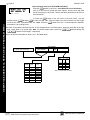
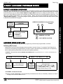
DIRECT ADDRESS PROGRAM MODE
DIRECT ADDRESS OVERVIEW
Direct Address Programming allows you to go directly to the address locations (up to 4095) and change the data entries
manually in order to customize your control panel options. Whereas the Easy Menu Program Mode guides you through
limited selections to get you started, Direct Address Program Mode allows you to change all options directly. It consists of up to 4095 address locations each with data entry locations as shown in the following diagram (below left). The
data entry location accepts data in one of three formats: Binary, Decimal and Hexadecimal (explained below in
"Address Mode Displays"). The following diagram (below right) illustrates a Decimal format data entry location (using
a GEM-RP1CAe2/GEM-K1CA keypad).
DATA ENTRY
LOCATION
ADDRESS
LOCATIONS
GEM-RP1CAe2/GEM-K1CA Keypad Display
Example
1
0000
0000 060
DATA ENTRY LOCATION:
(One of three formats):
• Binary (Bit)
• Decimal
• Hexadecimal
1
2
D
= ADDRESS LOCATION
= DATA ENTRY LOCATION
ADDRESS MODE DISPLAYS
There are three types of address displays when programming in Direct Entry Program Mode, as follows:
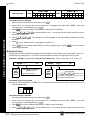
A) Binary (Bit) Format
Settings (such as Zone Features) display and accept data in "number" format. For example, Zone Features are
turned on by the pressing of keypad buttons 1 through 8, with the activated Zone(s) displaying the corresponding
decimal digit (replacing deactivated zones which are signified by dashes).
EXAMPLE: BIT Format with the GEM-RP1CAe2/GEM-K1CA: Program Zones 2, 4, 5 and 7 as Exit/Entry Follower Zones.
1218
Address
1218
"Exit/Entry
Follower"
- - - - - - - -
B
DATA ENTRY LOCATION:
Binary (Bit) Format
• No zones yet activated
1218
Address
1218
"Exit/Entry
Follower"
- 2 - 4 5 - 7 -
B
DATA ENTRY LOCATION:
Binary (Bit) Format
Press 2 4 5 and 7 in
order to activate Zones 2, 4, 5, and 7. (The "B"
on the right indicates "Binary" format).
DETERMINE THE DATA ENTRIES
Referring to ZONE FEATURES in the Programming Worksheets that follow, the Exit/Entry Follower for Zones 1
through 8 are located at address 1218.
L
NAPCO Security Systems
X
GEM-P3200 Programming Instructions
DIRECT ADDRESS PROGRAM MODE
0000
TO
4095
2
Page 16
WI818G 10/05
ZONES 1
ZONE FEATURES
ADDR Z1
1
Exit/Entry Follower
8
ZONES 9
Z2
Z3
Z4
Z5
Z6
Z7
Z8
2
3
4
5
6
7
8
6
7
8
1218
ADDR
16
Z9 Z10 Z11 Z12 Z13 Z14 Z15 Z16
1
2
3
4
5
6
7
8
1318
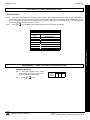
PROGRAM THE DATA ENTRIES
1. Enter the panel's Dealer Security Code, then press R.
2. Answer NO to all questions until “ACTIVATE PROGRAM Y/N” is displayed; then press YES. NOTE: If you pass
“ACTIVATE PROGRAM”, scroll backward using B.
3. Press C to enter the Address Program Mode. Address "0000" will display.
DIRECT ADDRESS PROGRAM MODE
4. Press 1218 to access Address 1218. The existing data will display and the cursor will
advance to the data field.
5. Press 6 7 8. The numbers 6,7 and 8 will appear on the keypad display indicating the zones
activated.
6. Press U to save. Address 1218 is now programmed with “6,7,8”.
7. Press R and enter another 4-digit address to continue programming--or--press C to exit and resume
normal keypad operation.
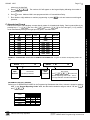
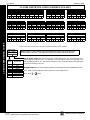
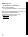
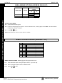
B) Decimal Format
Settings (such as Entry and Exit Delay) display and accept data in decimal format, as a 3 digit number. Data is entered directly, by pressing keys 0 – 9, with the cursor automatically moving to the right upon each key press.
EXAMPLE: DECIMAL Format with the GEM-RP1CAe2/GEM-K1CA: Program Abort Delay to be 15 seconds.
2406 - - -
D
DATA ENTRY LOCATION:
Decimal Format
Address
2406
"Abort
Delay"
• No time yet entered
2406
Address
2406
"Abort
Delay"
015
D
DATA ENTRY LOCATION:
Decimal Format
Press 0 1 5 in order to set
"Abort Delay" to 15 seconds. The "D" on the
right indicates "Decimal" format.
DETERMINE THE DATA ENTRIES
Referring to SYSTEM DELAYS & TIMEOUTS in the Programming Worksheets that follow, the Abort Delay is located at address 2406:
ABORT
ADDRESS 2406
DELAY
(sec.)
[Default = 000]
PROGRAM THE DATA ENTRIES
1. Enter the panel's Dealer Security Code, then press R.
2. Answer NO to all questions until “ACTIVATE PROGRAM Y/N” is displayed; then press YES. NOTE: If you pass
“ACTIVATE PROGRAM”, scroll backward using B.
3. Press C to enter the Address Program Mode. Address "0000" will display.
4. Press 2406 to access Address 2406. The existing data will display and the cursor will
X
GEM-P3200 Programming Instructions
L
NAPCO Security Systems
Page 17
WI818G 10/05
advance to the data field.
5. Press 015. The numbers 015 will appear on the keypad display indicating the number of
seconds entered.
6. Press U to save. Address 2406 is now programmed with a 15-second Abort Delay.
7. Enter another 4-digit address to continue programming or press C to exit and resume normal keypad
operation.
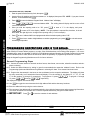
C) Hexadecimal Format
Data such as Report Codes displays, accepts data by means of a Hexadecimal display. Data is entered directly, by
pressing keys 1 – 9, G0 for zero, and G 1 through G 5 for hex B through F (11-15), with the
cursor automatically moving to the right upon key press. See table below.
HEXADECIMAL ENTRIES
PRESS
N
KEYPAD
DISPLAYS
ENTRY
TOTAL
PRESS
N
KEYPAD
DISPLAYS
blank
0
•
8
8
8
1
1
1
9
9
9
2
2
2
10
G 0
0
3
3
3
11
G 1
B
4
4
4
12
G 2
C
5
5
5
13
G 3
D
6
6
6
14
G 4
E
7
7
7
15
G 5
F
EXAMPLE: HEXADECIMAL Format with the GEM-RP1CAe2/GEM-K1CA: Program an Ambush CS Reporting Code to be
"1B".
0900
Address
0900
"Ambush"
- -
H
0900
DATA ENTRY LOCATION:
Hex Format
• No data yet entered
Address
0900
"Ambush"
1 B
H
DATA ENTRY LOCATION:
Hex Format
Press 1G1 in order to set
"Ambush" Reporting code to "1B". The "H"
on the right indicates "Hexadecimal" format.
DETERMINE THE DATA ENTRIES
Referring to CS REPORTING CODES in the Programming Worksheets that follow, Ambush is located at address
0900. In the "Keypad Reporting Codes" table, the data entries needed to assign a code of "1B" are "1"
and "G1".
KEYPAD REPORTING
CODES
Ambush
Panic
ADDRESS
0900-0904
LEFT
ADDR
RIGHT
1
0900
B
Fire
Auxiliary
Tamper
L
NAPCO Security Systems
0901
0902
0903
0904
X
GEM-P3200 Programming Instructions
DIRECT ADDRESS PROGRAM MODE
ENTRY
TOTAL
Page 18
WI818G 10/05
PROGRAM THE DATA ENTRIES
1. Enter the panel's Dealer Security Code, then press R.
2. Answer NO to all questions until “ACTIVATE PROGRAM Y/N” is displayed; then press YES. NOTE: If you pass “ACTIVATE
PROGRAM”, scroll backward using B.
3. Press C to enter the Address Program Mode. Address "0000" will display.
4. Press 0900 to access Address 0900. The existing data will display and the cursor will advance to the data field.
5. Since you wish the reporting code to be "1B", press 1 to enter a "1" in the display, and press
G1 to enter a "B" in the display. NOTE: The right address is reported first, therefore, in the ad-
dress table, the right digit is the 1st digit of the reporting code ("1" in this example).
DIRECT ADDRESS PROGRAM MODE
6. Press U to save. Address 0900 is now programmed with an Ambush reporting code of "1B".
7. Press R and enter another 4-digit address to continue programming--or--press C to exit and resume
normal keypad operation.
PROGRAMMING CONVENTIONS USED IN THIS MANUAL
The Keypad Programming Worksheets that follow are provided as an address-programming reference to help the installer modify his custom default program or to make minor field alterations to an existing panel program. It is recommended that the panel be uploaded to NAPCO's PCD-Windows software following any keypad programming and that
the PCD-Windows's error-check feature be utilized to reduce the possibility of programming omissions or conflicts.
3
Keep the Keypad Programming Worksheets on file for future reference.
General Programming Steps
1. Contact the central station to ascertain receiver format, data format, event codes, subscriber numbers and telephone number(s).
2. Select the desired features by writing in (pencil recommended) the respective “address” boxes.
Refer to the
Programming Options and Worksheets for guidance in selecting the “data” to be entered into those boxes.
3. Program the data entered in the boxes on the worksheets into the respective addresses.
The display will show
the entry numerically, but if hexadecimal format will display “0” for the number 10, and letters “B”, “C”, “D”, “E”, and
“F” for the numbers 11 through 15, respectively. To program a 10, press G 0. To program 11 through
15, press G 1 through G 5, respectively.
The displays will appear after a brief delay.
Use R to toggle the cursor between the 4-digit address field and the data entry locations.
Enter the address directly using the number buttons.
The contents of the address will be read automatically, along with the feature name and programming information.
The cursor will advance to the data field. Enter the required data directly using the number buttons.
IMPORTANT:
Press U or D to save the contents of each address.
EXIT DIRECT ADDRESS PROGRAM MODE: When done, press C to exit and resume normal keypad operation.
X
GEM-P3200 Programming Instructions
L
NAPCO Security Systems
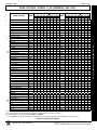
Page 19
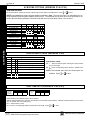
WI818G 10/05
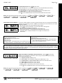
SYSTEM DELAYS & TIMEOUTS (ADDRESS 0000-0002, 2402, 2406, 2414 & 3902)
ADDRESS 0000
EXIT
DELAY
(sec.)
ENTRY
DELAY 1
(sec.)
[Default = 030]
[Default = 060]
ADDRESS 0001
ENTRY
DELAY 2
(sec.)
ADDRESS 0002
[Default = 030]
Aux.
Output
Access
Control
Timeout
(sec.)
ADDRESS 2402
ABORT
DELAY
(sec.)
ADDRESS 2406
[Default = 000]
[Default = 000]
Telephone ADDRESS 2414
Line Test
Delay
(x15 sec.)
Select delay/timeout (0-255 seconds).
[Default = 000]
EXIT/ENTRY DELAYS: Apply only to zones programmed with the following options “Exit/Entry 1, Exit/Entry
2, Exit/Entry Follower”. For UL Installations, the maximum exit delay is 60 seconds and the maximum entry
delay is 45 seconds. NOTE: Sensor Watch Time Options are similar to above table, except in hours.
CS Telco 3 ADDRESS 3902
Report
Delay
(sec.)
Press U or D to save.
[Default = 000]
SYSTEM DE LAY S & TIM EOU TS (ADDRESS 2407, 2408 & 4088)
CHIME
ADDRESS 2407
AC Fail
TIME
Report Delay
(¼sec.)
(x10 min.)
[Default = 008 x ¼ sec. = 2 sec.]
ADDRESS 2408
Sensor Watch
Delay (Hr.)
[Default = 008]
ADDRESS 4088
[Default = 024]
1. Enter delay/timeout in corresponding address locations above.
Note: All entries for address 2407 are in quarter seconds (.25 seconds).
Therefore, the default of 008 results in a 2 second timeout.
2. Press U or D to save.
L
NAPCO Security Systems
X
GEM-P3200 Programming Instructions
SYSTEM DELAYS/TIMEOUTS
WARNING: Timers have uncertainty of +/-1 sec, so a "time" of 1 second may actually timeout IMMEDIATELY.
Page 20
WI818G 10/05
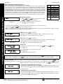
SYST EM DE LA YS & TIMEOU TS ( ADDRESS 2400, 2401, 2403-2405, 4082 & 4083)
Reset Output ADDRESS 2400
Timeout
(min.)
[Default = 000]
Aux. Output
Timeout
(min.)
ADDRESS 2401
Burg. Alarm
Output
Timeout
(min.)
[Default = 000]
ADDRESS 2403
ADDRESS 2404
Pulse Alarm
Output
Timeout
(min.)
[Default = 015]
[Default = 015]
ADDRESS 2405
[Default = 000]
Report
Cancel
Window
(min or sec.)
1. Select delay/timeout (0-255 min.).
2. Enter in corresponding address locations above and right.
3. Press U or D to save.
SYSTEM DELAYS/TIMEOUTS & KEYPAD CODES
Fire Output
Timeout
(min.)
ADDRESS 4082
[Default = 000]
V.1 or less = sec.
V.3 or greater = min.
Program for at least 5 minutes
in a CP-01 installation.*
OUTPUT TIMEOUTS: If a timeout of “0 min.” is selected, then the output will
remain active (ON) until the system is reset or disarmed. For UL Residential Installations, the minimum timeout is 4 minutes. For UL Commercial Installations,
the minimum timeout is 15 minutes.
Auto Disarm
Rearm Delay
(min.)
ADDRESS 4083
[Default = 000]
*Address 4082: When "Enable CP-01 Features" is selected
in the Easy Program menu, this time is set to 7 minutes.
KEYPAD SYS TE M CODE S (ADDR ESS 0490-0495 & 0500-0502)
Panel Access
Code
ADDRESS 0490-0492
0490
0491
0492
L
R
L
R
L
R
[Default = blank (•) blank (•) from address 0490-0492]
PANEL ACCESS CODE: Enter up to 6 digits to activate a door strike while the area is disarmed.
1. Enter in both left and right digits of address locations.
2. Valid entries are: 0-9.
Note: Also, “Access Control on Aux. Output” (Address 2418) and “Aux. Output Access Control Timeout” (Address 2402) must both
be enabled.
Ambush
Code
ADDRESS 0495
LEFT
RIGHT
[Default = 99]
AMBUSH CODE: Enter a 2-digit code used just prior to disarming and will activate an Ambush Condition, causing a SILENT report to
be sent to the central station.
1. Enter in both left and right digits of address locations.
2. Valid entries are: 0-9.
Note: Also, “Enable Keypad Ambush” (Address 2440-2446), “Report on Ambush Alarm” (Address 1125, 1127, 1135 & 1137) must be
enabled and “Ambush Reporting Code” (Address 0900) must be provided.
Dealer Security
Code
ADDRESS 0500-0502
0500
0501
0502
L
R
L
R
L
R
[Default = blank (•) blank (•) from address 0500-0502]
DEALER SECURITY CODE: Enter up to 6 digits to be used by the dealer to enter programming.
1. Enter in both left and right digits of address locations.
2. Valid entries are: 0-9.
Note: If left blank, the Master Security Code must then be used to enter programming.
X
GEM-P3200 Programming Instructions
L
NAPCO Security Systems
Page 21
WI818G 10/05
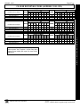
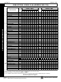
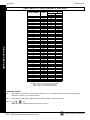
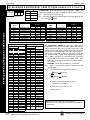
C S R EC EI VE R FO RM A T O PTIO NS ( ADDR ESS 0520, 0521, 0525, 0526, 0550, 0551, 0575 & 0576)
ADDRESS 0525
ADDRESS 0575
ADDRESS 0550
CS Receiver 1
Format
CS Receiver 3
Format
CS Receiver 2
Format
Default for CS Receiver 1 Format depends on Easy Menu Question “RCVR FORMAT”. [Default = •(blank) E] for CS Receivers 1, 2 and 3 Formats.
DATA ENTRIES
LEFT
RIGHT
CS RECEIVER FORMATS
blank (•)
blank (•)
blank (•)
1
2
3
4
5
8
9
0
B
C
D
E
F
1
blank (•)
blank (•)
blank (•)
blank (•)
blank (•)
blank (•)
blank (•)
blank (•)
blank (•)
blank (•)
blank (•)
blank (•)
Ademco Slow, Silent Knight Slow
Sescoa, Vertex, DCI, Franklin Fast
Radionics Fast
Silent Knight Fast
Radionics, DCI, Franklin Slow
Universal High Speed
Radionics BFSK
FBI 4/3/1
Radionics Modem 2
SIA
Ademco Point ID
Ademco Express
Pager
Disabled
Radionics Modem IIe
1. Select the desired CS Receiver Format from the table shown.
2. Enter in the corresponding digit address locations for each
CS
Receiver.
NOTE: Dark shaded data value box shows option not available.
Leading Digits
for Pager
Format
(1st Digit)
ADDRESS 0520
Leading Digits
for Pager
Format
(2nd Digit)
[Default = blank (•) blank (•)]
ADDRESS 0521
[Default = blank (•) blank (•)]
LEADING DIGITS FOR PAGER FORMAT: In Pager Format reporting, the message typically begins with “00”. However, for some
pager services, this will cause the Pager's Voice Mail feature to activate. This option allows you to program these digits to any
number desired. Typical Pager report is “003 022 1234”, where 3 is the Event, 22 is the zone, and 1234 is the Subscriber ID
number. For example, if the Leading Digits are programmed as “98”, the Pager report will now appear as “983 022 1234”.
1. Enter in 1st and 2nd Leading Digits in right digit only (left digit is not used) as shown.
2. Valid entries are: 0-9.
0526
Press U or D to save
CS Receiver 1 Options
0551
Option
Default
CS Receiver 2 Options
Option
Default
1400Hz Handshake/Kissoff *
OFF
1
1400Hz Handshake/Kissoff *
OFF
1
OFF
2
2300Hz Handshake/Kissoff *
OFF
2
2300Hz Handshake/Kissoff *
OFF
3
Enable Zone Number on Pulse Alarm
OFF
3
Enable Zone Number on Pulse Alarm
OFF
4
Single Digit Only
OFF
4
Single Digit Only
OFF
5
Sum Check
OFF
5
Sum Check
OFF
6
3/1 with Extended Restores
OFF
6
3/1 with Extended Restores
OFF
7
Report to TCP/IP Receiver or AES (Telco 1)**
OFF
7
Report to TCP/IP Receiver or AES (Telco 2)**
OFF
8
RESERVED
OFF
8
RESERVED
0576 CS Receiver 3 Options
Default for CS Receiver 1 Format depends on Easy Menu Question “RCVR
FORMAT”. [Default = •(blank) E] for CS Receivers 2 and 3 Formats.
Option
Default
OFF
1
1400Hz Handshake/Kissoff *
OFF
2
2300Hz Handshake/Kissoff *
OFF
3
Enable Zone Number on Pulse Alarm
OFF
4
Single Digit Only
OFF
5
Sum Check
OFF
6
3/1 with Extended Restores
OFF
7
Report to TCP/IP Receiver or AES (Telco 3)**
OFF
8
RESERVED
L
NAPCO Security Systems
CS RECEIVER FORMATS: Up to 3 CS Formats may be programmed.
1. Select the desired CS Receiver Format from the table shown.
2. Enter the corresponding digit in the address location for each CS
Receiver. NOTE: Dark shaded data value box shows option not
available. Press [Enter] of [ON/OFF] to save.
NOTES:
* If both are selected, 1400Hz has priority over 2300Hz.
** For NAPCO NetLink™ installations only: For each telephone number desired, enable to allow the panel to report alarms via the NL-MOD
accessory. See WI1242 for more information.
X
GEM-P3200 Programming Instructions
CS RECEIVER FORMAT OPTIONS
blank (•)
CS RECEIVER FORMATS: Up to 3 CS Formats may be programmed.
Page 22
WI818G 10/05
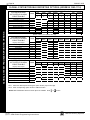
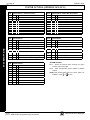
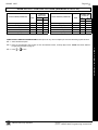
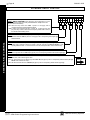
CS RECEIVER T ELEPH ONE NUMBERS (ADDRESS 05 27-0546, 0552-0571, 0577-05 96)
CS RECEIVER TELEPHONE NUMBERS & DOWNLOAD/CALLBACK OPTIONS
ADDRESS 0527-0546 (DIGITS 1-20)
CS Receiver
1 Telephone 0527 0528 0529 0530 0531 0532 0533 0534 0535 0536 0537 0538 0539 0540 0541 0542 0543 0544 0545 0546
Number
(Digits 1-20)
ADDRESS 0552-0571 (DIGITS 1-20)
CS Receiver
2 Telephone 0552 0553 0554 0555 0556 0557 0558 0559 0560 0561 0562 0563 0564 0565 0566 0567 0568 0569 0570 0571
Number
(Digits 1-20)
ADDRESS 0577-0596 (DIGITS 1-20)
CS Receiver
3 Telephone 0577 0578 0579 0580 0581 0582 0583 0584 0585 0586 0587 0588 0589 0590 0591 0592 0593 0594 0595 0596
Number
(Digits 1-20)
Default
for
CS
Rec eiv er
1
Telephone Number
depends on Easy
Menu
Question
“CENTRAL PHONE
#”.
[Default = blank (•)]
across digits 1-20 for
CS Receiver
Telephone Numbers
2 and 3.
CS RECEIVER TELEPHONE NUMBERS: Enter telephone numbers for any of the three CS Receivers (Telco 1, 2 & 3).
1. Enter up to 20 digits from left to right. NOTE: Leave trailing boxes blank (•).
2. Valid entries are: 1-9, B = *button, C = #button, D = 3 sec. pause, E = Wait for dial tone, F = ignore location
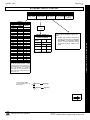
DOWNL OAD/CAL LBACK OP TI ONS
Answer on
Ring Number
( A D DR E S S 4 08 9, 06 00 - 0 6 1 9, 0 6 2 5 - 06 4 7, 10 2 2 & 1 0 2 3)
ANSWER ON RING NUMBER: Enter the number of rings before automatic pickup by the control panel
when downloading from a computer (see Glossary in WI817). Initial value of 000 becomes 15 rings.
1. Enter digits only.
ADDRESS 4089
2.
[Default = 015]
Valid entries are: 003-015. NOTE: Default is 15 Rings. Press U or D to save.
ADDRESS 0600-0619 (DIGITS 1-20)
Callback
Telephone 0600 0601 0602 0603 0604 0605 0606 0607 0608 0609 0610 0611 0612 0613 0614 0615 0616 0617 0618 0619
Number 1
(Digits 1-20)
[Default = blank (•) for all digits 1-20]
ADDRESS 0625-0644 (DIGITS 1-20)
Callback
Telephone
0625 0626 0627 0628 0629 0630 0631 0632 0633 0634 0635 0636 0637 0638 0639 0640 0641 0642 0643 0644
Number 2
(Digits 1-20)
[Default = blank (•) for all digits 1-20]
CALLBACK TELEPHONE NUMBERS: Enter telephone numbers to be used when downloading from a computer.
1. Enter digits only.
2. Enter up to 20 digits from left to right. NOTE: Leave trailing boxes blank (•).
3. Valid entries are: 0-9, B = *button, C = #button, D = 3 sec. pause, E = Wait for dial tone, F = ignore location.
ADDRESS 0645-0647
Download
Security Code
0645
0646
0647
[Default = blank (•) blank (•)]
DOWNLOAD SECURITY CODE: Enter up to 6 digits to be used
for remote access when downloading from a computer.
1. Enter digits in address locations above.
2. Valid entries are: 0-9.
Callback
Telephone
No. Select
Press U or D to save.
ADDRESS 1022
Auto Download
ID No.
[Default = blank (•) blank (•)]
ADDRESS 1023
Valid entries - 01-99
CALLBACK TELEPHONE NO. SELECT: Enter
either “1” for Callback Telephone Number 1 or
“2” for Callback Telephone Number 2.
[Default = blank (•) blank (•)]
1. Valid entries are: 1 or 2.
Note: Download Security Code must match the code entered in
the PCD-Windows Quickloader Download Software.
X
GEM-P3200 Programming Instructions
L
NAPCO Security Systems
Page 23
WI818G 10/05
CS SUBSCRIBER ID NUMBERS (A DDRESS 0 6 50 -0 78 7)
CS TELCO 1 SUBSCRIBER OPENING/CLOSING ID NUMBERS
AREA 1
AREA 2
ADDRESS 0650-0653
(DIGITS 1-4)
0650 0651 0652 0653
ADDRESS 0654-0657
(DIGITS 1-4)
0654 0655 0656 0657
AREA 1
AREA 2
SYSTEM
ADDRESS 0682-0685
(DIGITS 1-4)
0682 0683 0684 0685
ADDRESS 0686-0689
(DIGITS 1-4)
0686 0687 0688 0689
ADDRESS 0714-0717
(DIGITS 1-4)
0714 0715 0716 0717
CS TELCO 2 SUBSCRIBER OPENING/CLOSING ID NUMBERS (BACKUP REPORTING)
AREA 1
AREA 2
ADDRESS 0720-0723
(DIGITS 1-4)
ADDRESS 0724-0727
(DIGITS 1-4)
0720 0721 0722 0723
0724 0725 0726 0727
CS TELCO 2 SUBSCRIBER EVENT ID NUMBERS (BACKUP REPORTING)
AREA 1
AREA 2
SYSTEM
ADDRESS 0752-0755
(DIGITS 1-4)
ADDRESS 0756-0759
(DIGITS 1-4)
0756 0757 0758 0759
ADDRESS 0784-0787
(DIGITS 1-4)
0784 0785 0786 0787
0752 0753 0754 0755
L
NAPCO Security Systems
X
GEM-P3200 Programming Instructions
CS SUBSCRIBER ID NUMBERS (TELCO 1 & 2)
CS TELCO 1 SUBSCRIBER EVENT ID NUMBERS
Page 24
WI818G 10/05
C S SUBSCRIBER ID NUMBERS (A DDRESS 0 79 0-08 5 7)
CS SUBSCRIBER ID NUMBERS (TELCO 3) & CS REPORTING CODES
CS TELCO 3 SUBSCRIBER OPENING/CLOSING ID NUMBERS
AREA 1
AREA 2
ADDRESS 0790-0793
(DIGITS 1-4)
0790 0791 0792 0793
ADDRESS 0794-0797
(DIGITS 1-4)
0794 0795 0796 0797
CS TELCO 3 SUBSCRIBER EVENT ID NUMBERS
AREA 1
AREA 2
SYSTEM
ADDRESS 0822-0825
(DIGITS 1-4)
ADDRESS 0826-0829
(DIGITS 1-4)
ADDRESS 0854-0857
(DIGITS 1-4)
0822 0823 0824 0825
0826 0827 0828 0829
0854 0855 0856 0857
Default for CS Telco 1 Subscriber Event ID Number (Area 1) depends on Easy Menu Question “ACCOUNT #”. [Default = blank (•) blank (•) blank (•)
blank (•)] for all other ID Numbers.
CS TELCO SUBSCRIBER ID NUMBERS: Enter the Subscriber Opening/Closing and Event ID Numbers for any of the 3 CS Receivers.
1. Enter 3 or 4 digits (depending on the CS receiver format) for each subscriber number from left to right.
NOTE: Leave trailing boxes blank (•).
2. Valid entries are: 1-9, 0 and B-F. NOTE: A is not permitted. Press [Enter] or ON/OFF] to save.
CS REPOR TIN G CODES (ADDRE SS 0859-0883)
ALARM/TROUBLE
REPORTING CODES
Cancel
Alarm Restore
Trouble
Trouble Restore
ADDRESS
0859-0862
LEFT
blank (•)
blank (•)
blank (•)
blank (•)
ADDR
0859
0860
0861
0862
RIGHT
[Default = blank (•) blank (•) from address 0859-0883]
OPENING/CLOSING
REPORTING CODES
ADDRESS 0864-0883
ADDR
Closing
Conditional Closing
Opening
blank (•)
blank (•)
blank (•)
0864
0865
0866
Opening after Alarm
Fail to Open
Fail to Close
blank (•)
0867
0868
0869
Telemetry Trouble
0882
Telemetry Fail
0883
CS SYSTEM REPORTING CODES:
1. Enter in corresponding address location (left and right digits).
NOTE: Left digit is the first digit and
right digit is the second digit in a two
digit CS receiver format.
2. Valid entries are: 1-9, 0 and B-F.
NOTE: A is not permitted.
3. To disable a code leave boxes blank
(•).
NOTE: Dark shaded data value box
shows option not available.
4. Press U or D to save.
X
GEM-P3200 Programming Instructions
L
NAPCO Security Systems
Page 25
WI818G 10/05
CS REPOR TIN G CODES (ADDRESS 0870-0904)
SYSTEM REPORTING
CODES
ADDRESS
0870-0880
LEFT
ADDR
SYSTEM REPORTING
CODES
RIGHT
ADDRESS
0890-0897
LEFT
ADDR
RIGHT
KEYPAD REPORTING
CODES
ADDRESS
0900-0904
LEFT
ADDR
Test Timer
Alarm Supervisory
0870
0871
Digital Dialer Test
RESERVED
0890
0891
Ambush
0900
Panic
0901
Bus Failure
0872
RESERVED
0892
Fire
0902
Memory Failure
Low Battery
0873
0874
Service Message
Program Change
0893
0894
Auxiliary
0903
Tamper
0904
AC Failure
EZM Tamper
0875
0876
RF Receiver Trouble
RF Tamper
0895
0896
RF Trouble
0897
Sensor Watch
0877
RESERVED
blank (•)
0878
blank (•)
RESERVED
blank (•)
0879
blank (•)
0880
CS SYSTEM REPORTING CODES:
1. Enter in corresponding address location
(left and right digits).
NOTE: Left digit is the first digit and right
digit is the second digit in a two digit CS
receiver format.
2. Valid entries are: 1-9, 0 and B-F.
NOTE: A is not permitted.
3. To disable a code leave boxes blank (•).
NOTE: Dark shaded data value box
shows option not available.
4. Press U or D to save.
CAUTION: For all 2-Digit Reporting Formats (see CS Receiver Format Options), use the following:
Reporting
Code
ADDRESS Loc.
LEFT
RIGHT
1
2
2nd Digit of Reporting Code
1st Digit of Reporting Code
Example: The 2-digit reporting code as shown is “21”.
CS AREA & SYS TEM R E POR TIN G OP TION S (ADD RESS 10 24 -102 7 )
AREAS 1
CS Area Reporting Options
ADDRESS
DISABLE OPENING REPORTS
1024
1025
DISABLE CLOSING REPORTS
A2
1
2
1027 CS System Report Options
Option
Default
L
OFF
1
Backup Report on Telco 2
OFF
2
Touch-tone Dialing Only *
ON
3
Touch-tone Dialing w/Rotary Backup *
OFF
4
Transmit “402” Opening/Closing Code
OFF
5
Cancel Next Test Timer on any Report
OFF
6
Disable Wait for Silence
OFF
7
Disable Wait for Handshake
OFF
8
Handshake for Local Telemetry
NAPCO Security Systems
2
A1
CS AREA & SYSTEM REPORTING OPTIONS:
1. Select the desired option entering the
option number (1-8) for each digit.
2. Enter corresponding option number in
address location.
NOTE: Dark shaded data value box shows option not available.
3.
Press U or D to save.
* NOTE: If neither TouchTone Dialing nor
TouchTone w/Rotary Backup is selected, then
system defaults automatically to Rotary Dialing.
Leave blank (•) to select Rotary Dialing.
X
GEM-P3200 Programming Instructions
CS REPORTING CODES & CS REPORTING OPTIONS
Telco Line Failure
[Default = blank (•) blank (•) from address 0870-0904]
RIGHT
Page 26
WI818G 10/05
CS ZONE REPORTING CODES
CS ZON E REP OR TING C ODES (A DDRESS 0 91 0-09 57)
ADDRESS 0910-0917
ZONES REPORT CODE (CONTROL PANEL)
ZONE 1 ZONE 2 ZONE 3 ZONE 4 ZONE 5 ZONE 6 ZONE 7 ZONE 8
0910
0911
0912
0913
0914
0915
0916
0917
ADDRESS 0918-0921
ZONES REPORT CODE (GROUP 1)
ZONE 9 ZONE 10 ZONE 11 ZONE 12
0918
0919
0920
0921
ADDRESS 0922-0925
ZONES REPORT CODE (GROUP 2)
ZONE 13 ZONE 14 ZONE 15 ZONE 16
0922
0923
0924
0925
ADDRESS 0926-0929
ZONES REPORT CODE (GROUP 3)
ZONE 17 ZONE 18 ZONE 19 ZONE 20
0926
0927
0928
0929
ADDRESS 0930-0933
ZONES REPORT CODE (GROUP 4)
ZONE 21 ZONE 22 ZONE 23 ZONE 24
0930
0931
0932
0933
ADDRESS 0934-0937
ZONES REPORT CODE (GROUP 5)
ZONE 25 ZONE 26 ZONE 27 ZONE 28
0934
0935
0936
0937
ADDRESS 0938-0941
ZONES REPORT CODE (GROUP 6)
ZONE 29 ZONE 30 ZONE 31 ZONE 32
0938
0939
0940
0941
ADDRESS 0942-0945
ZONES REPORT CODE (GROUP 7)
ZONE 33 ZONE 34 ZONE 35 ZONE 36
0942
0943
0944
0945
ADDRESS 0946-0949
ZONES REPORT CODE (GROUP 8)
ZONE 37 ZONE 38 ZONE 39 ZONE 40
0946
0947
0948
0949
ADDRESS 0950-0953
ZONES REPORT CODE (GROUP 9)
ZONE 41 ZONE 42 ZONE 43 ZONE 44
0950
0951
0952
0953
ADDRESS 0954-0957
ZONES REPORT CODE (GROUP 10)
ZONE 45 ZONE 46 ZONE 47 ZONE 48
0954
0955
0956
0957
Default for Group Zone Report Codes depends on Easy Menu Question “RCVR. FORMAT”.
ZONE REPORT
CODE OPTIONS
DATA ENTRIES
DATA
ENTRIES
NOTE: Zones 1-8 are included in the control panel and Zones 9-32 are EZM Zones.
Zones 33-48 are wireless. See Address 2555-2560 to enable “EZM Zone Groups”.
MODEM CODE
1
2
3
4
Burglary
Hold up
7
8
Gas Alarm
Heat Alarm
0
Auxiliary Alarm
B
24 Hour Auxiliary
X
PULSE EVENT CODE will be the first digit of the 2 digit reporting code. The second digit will be the
second digit of the reporting zone. For example, for zone 9 (address 0918), if the right digit is “3",
then the reporting code is “39”. With another example, for zone 15 (address 0924), if the right digit is
“4", then the reporting code is “45”.
Fire *
Panic
MODEM CODES determine the zone types reported for the following formats: SIA and ADEMCO Point ID.
1.
2.
Select the desired Modem Code for each zone from the table shown.
Press U or D to save.
GEM-P3200 Programming Instructions
L
NAPCO Security Systems
Page 27
WI818G 10/05
CS USER REP OR TING C ODES (A DDRESS 1 0 30 -1 07 4)
USERS 1
Enable Users to Report
User Opening Telco 1
User Closing Telco 1
User Opening Telco 3
User Closing Telco 3
1
2
3
4
5
User Closing Telco 1
User Opening Telco 3
User Closing Telco 3
User Closing Telco 1
User Opening Telco 3
User Closing Telco 3
8
16
U9 U10 U11 U12 U13 U14 U15 U16
1
2
3
4
5
6
7
8
24
USERS 25
2
3
4
5
6
7
ADDR U25 U26 U27 U28 U29 U30 U31 U32
8
1032
1045
1058
1071
32
1
2
3
4
5
6
7
8
1033
1046
1059
1072
40
USERS 41
ADDR U33 U34 U35 U36 U37 U38 U39 U40
1
2
3
4
5
6
7
8
1034
1047
1060
1073
48
ADDR U41 U42 U43 U44 U45 U46 U47 U48
1
2
3
4
5
6
7
8
1035
1048
1061
1074
NOTE: These opening events will report as the user
number shown. Also, Keyfobs 1-8 (see Easy Menu
Program Driven Mode) will report as Users 25-32,
respectively.
L
NAPCO Security Systems
X
GEM-P3200 Programming Instructions
CS USER REPORTING CODES
User Opening Telco 1
7
U20
ADDR U17 U18 U19
U21 U22 U23 U24
4
USERS 33
Enable Users to Report
6
ADDR
1031
1044
1057
1070
1
User Opening Telco 1
USERS 9
1030
1043
1056
1069
USERS 17
Enable Users to Report
8
ADDR U1 U2 U3 U4 U5 U6 U7 U8
Page 28
WI818G 10/05
GLOBAL SYS TE M TR OUBLE RE P ORTIN G OPT IONS (ADDRES S 1082-1116)
GLOBAL SYSTEM TROUBLE REPORTING OPTIONS
GLOBAL SYSTEM EVENT/TROUBLE
SYSTEM RESPONSE
ACTIVATED BY GLOBAL
EVENT/TROUBLE
ADDR
Burglary Alarm Output
Pulsed Burg. Output
Fire Output (Lug E9)
Reset Relay
Auxiliary Relay
Report Event Telco 1
Report Restore Telco 1
Report Event Telco 3
Report Restore Telco 3
1082
1083
1084
1085
1086
1087
1088
1091
1092
TEST
TIMER
ALARM
SUPERV.
COMM.
BUS 1
MEMORY
FAILURE
LOW
BATTERY
AC FAIL
EZM
TAMPER
SENSOR
WATCH
1
2
3
4
5
6
7
8
[Default = blank (•) from address 1082-1092].
SYSTEM RESPONSE
ACTIVATED BY GLOBAL
EVENT/TROUBLE
GLOBAL SYSTEM EVENT/TROUBLE
ADDR
TELCO
FAIL
RSRVD.
Telemetry
Trouble
Telemetry
Failure
RSRVD.
RSRVD.
RSRVD.
RSRVD.
1
2
3
4
5
6
7
8
Burglary Alarm Output
1094
Pulsed Burg. Output
1095
Fire Output (Lug E9)
1096
Reset Relay
1097
Auxiliary Relay
1098
Report Event Telco 1
1099
Report Restore Telco 1
1100
Report Event Telco 3
1103
Report Restore Telco 3
1104
[Default = blank (•) from address 1094-1104] * NOTE: Keypad Aux. is not to be selected for UL Installations.
SYSTEM RESPONSE
ACTIVATED BY GLOBAL
EVENT/TROUBLE
GLOBAL SYSTEM EVENT/TROUBLE
ADDR
Digital
Dialer Test
RSRVD.
RSRVD.
1
2
3
SERVICE PROGRAM RF RCVR.
MESSAGE CHANGE TROUBLE
4
5
6
RF
TAMPER
RF
TROUBLE
7
8
Burglary Alarm Output
1106
Pulsed Burg. Output
1107
Fire Output (Lug E9)
1108
Reset Relay
1109
Auxiliary Relay
1110
Report Event Telco 1
1111
Report Restore Telco 1
1112
Report Event Telco 3
1115
Report Restore Telco 3
1116
[Default = blank (•) blank (•) from address 1106-1116] * NOTE: Keypad Aux. is not to be selected for UL Installations.
1.
2.
Select the desired option entering the option number (1-8) for each digit.
Enter corresponding option number in address location.
NOTE: Dark shaded data value box shows option not available. Press U or D to save.
X
GEM-P3200 Programming Instructions
L
NAPCO Security Systems
Page 29
WI818G 10/05
AREA SYST EM T ROUBLE R EPORTING OP TI ONS (ADD RESS 11 20 -1 137 )
AREA 1 SYSTEM EVENT/TROUBLE
SYSTEM RESPONSE
ACTIVATED BY AREA 1
EVENT/TROUBLE
ADDR
Pulsed Burg. Output
1120
Burglary Output
1121
Fire Output (Lug E9)
1122
Reset Relay
1123
Auxiliary Relay
1124
Report Alarm Telco 1
Report Alarm Telco 3
1125
1127
AMBUSH
KEYPAD
PANIC
KEYPAD
FIRE
KEYPAD
AUX.
KEYPAD
TAMPER
FAIL TO
OPEN
FAIL TO
CLOSE
RSRVD.
1
2
3
4
5
6
7
8
Default ON
Default ON
Default ON
Defaults as noted from address 1120-1127]
ADDR
Pulsed Burg. Output
1130
Burglary Output
1131
Fire Output (Lug E9)
1132
Reset Relay
1133
Auxiliary Relay
1134
Report Alarm Telco 1
Report Alarm Telco 3
1135
1137
AMBUSH
KEYPAD
PANIC
KEYPAD
FIRE
KEYPAD
AUX.
KEYPAD
TAMPER
FAIL TO
OPEN
FAIL TO
CLOSE
RSRVD.
1
2
3
4
5
6
7
8
Default ON
Default ON
Default ON
Default ON
Default ON
Default ON
[Defaults as noted from address 1130-1137]
1.
2.
Select the desired option entering the option number (1-8) for each digit.
Enter corresponding option number in address location.
NOTE: Dark shaded data value box shows option not available.
3.
L
Press U or D to save.
NAPCO Security Systems
X
GEM-P3200 Programming Instructions
AREA SYSTEM TROUBLE REPORTING OPTIONS
AREA 2 SYSTEM EVENT/TROUBLE
SYSTEM RESPONSE
ACTIVATED BY AREA 2
EVENT/TROUBLE
Page 30
WI818G 10/05
ZONE OPTI ONS / ZONE S 1-16 (AD DRESS 120 0 -13 8 6)
ZONES 1
ZONE OPTIONS
ADDR Z1
ZONE OPTIONS / ZONES 1-16
1
8
ZONES 9
Z2
Z3
Z4
Z5
Z6
Z7
2
3
4
5
6
7
16
Z8 ADDR Z9 Z10 Z11 Z12 Z13 Z14 Z15 Z16
8
1
50ms Loop Response (A)
1200
20ms Loop Response (A)
Priority
1201
1202
1302
Priority with Bypass
1203
1303
Auto-Bypass
1204
1304
Selective Bypass
1205
1305
Keyswitch Arming
1206
1306
Auto-Bypass Re-entry
1207
1307
Pre-Alarm Warning
1208
1308
Never Arm
1209
1309
24-Hour Zone
1210
1310
Burg. Alarm Output
1211
1311
Pulsed Alarm Output
1212
1312
Fire Output (Lug E9)
1213
1313
Reset Relay
1214
1314
Auxiliary Relay
1215
1315
Entry/Exit 1
1216
1316
Entry/Exit 2
1217
1317
Exit/Entry Follower
1218
1318
Auto Reset
1219
1319
Swinger Shutdown
1220
1320
Chime
1221
1321
Abort Delay
1222
1322
Power-up Delay
1223
1323
Day Zone Open
1224
1324
Day Zone Short
1225
1325
Alarm on Day Zone
1226
1326
RPT Alarm Tel 1
1227
1327
RPT Alarm Restore Tel 1
1228
1328
RPT Trouble Tel 1
1229
1329
RPT Trouble Restore Tel 1
1230
1330
RPT Alarm Tel 3
1235
1335
RPT Alarm Restore Tel 3
1236
1336
RPT Trouble Tel 3
1237
1337
RPT Trouble Restore Tel 3
1238
1338
No EOL Resistor
1239
1339
Sensor Watch
1240
1340
Trouble on Open
1241
1341
Trouble on Short
1242
1342
Trouble on Night Open
1243
1343
Zone Area 1
1244
1344
Zone Area 2
1245
1345
2-Wire Smoke Detectors (B)
1252
RESERVED
1253
1353
Zone ANDing Group 1
1254
1354
Zone ANDing Group 2
1255
1355
Interior #1 Bypass
1262
1362
Interior #2 Bypass
1263
1363
Keypad Sounder on Alarm
1264
1364
Fire (C)
1275
1375
Fire Alarm Verification (C)
1276
1376
Interior (STAY) Bypass
1284
1384
Chime 2
1286
1386
2
3
4
5
6
7
8
When the Easy Program Menu is used, these features are enabled by default (for new panels or after a Cold Start (address 4093)). Zone Area 1
is enabled for the first 8 zones only, by default
Do not program if "K Series" keypads (with "P" and "Q" buttons) are used in the system.
See Zone Options on Page 33.
Disable Auto-Reset on non-fire zones for SIA CP-01 installations.
In UL installations, all Fire Zones must also be programmed for "Pulse Burg Output Cadence" (Address 2422, press 1 (bit zero)).
X
GEM-P3200 Programming Instructions
L
NAPCO Security Systems
Page 31
WI818G 10/05
ZONE OPTI ONS / ZONE S 17 -32 (A DDRESS 1 40 2 -1 58 6)
ZONES 17
ZONE OPTIONS
24
ZONES 25
32
ADDR Z17 Z18 Z19 Z20 Z21 Z22 Z23 Z24 ADDR Z25 Z26 Z27 Z28 Z29 Z30 Z31 Z32
1
2
3
4
5
6
7
8
1
1402
1502
Priority with Bypass
1403
1503
Auto-Bypass
1404
1504
Selective Bypass
1405
1505
Keyswitch Arming
1406
1506
Auto-Bypass Re-entry
1407
1507
Pre-Alarm Warning
1408
1508
Never Arm
1409
1509
24-Hour Zone
1410
1510
Burg. Alarm Output
1411
1511
Pulsed Alarm Output
1412
1512
Fire Output (Lug E9)
1413
1513
Reset Relay
1414
1514
Auxiliary Relay
1415
1515
Entry/Exit 1
1416
1516
Entry/Exit 2
1417
1517
Exit/Entry Follower
1418
1518
Auto Reset
1419
1519
Swinger Shutdown
1420
1520
Chime
1421
1521
Abort Delay
1422
1522
Power-up Delay
1423
1523
Day Zone Open
1424
1524
Day Zone Short
1425
1525
Alarm on Day Zone
1426
1526
RPT Alarm Tel 1
1427
1527
RPT Alarm Restore Tel 1
1428
1528
RPT Trouble Tel 1
1429
1529
RPT Trouble Restore Tel 1
1430
1530
RPT Alarm Tel 3
1435
1535
RPT Alarm Restore Tel 3
1436
1536
RPT Trouble Tel 3
1437
1537
RPT Trouble Restore Tel 3
1438
1538
No EOL Resistor
1439
1539
Sensor Watch
1440
1540
Trouble on Open
1441
1541
Trouble on Short
1442
1542
Trouble on Night Open
1443
1543
Zone Area 1
1444
1544
Zone Area 2
1445
1545
RESERVED
1453
1553
Zone ANDing Group 1
1454
1554
Zone ANDing Group 2
1455
1555
Interior #1 Bypass
1462
1562
Interior #2 Bypass
1463
1563
Keypad Sounder on Alarm
1464
1564
Fire (C)
1475
1575
Fire Alarm Verification (C)
1476
1576
Interior (STAY) Bypass
1484
1584
Chime 2
1486
1586
2
3
4
5
6
7
8
When the Easy Program Menu is used, these features are enabled by default (for new panels or after a Cold Start (address 4093)).
Do not program if "K Series" keypads (with "P" and "Q" buttons) are used in the system.
Disable Auto-Reset on non-fire zones for SIA CP-01 installations.
In UL installations, all Fire Zones must also be programmed for "Pulse Burg Output Cadence" (Address 2422, press 1 (bit zero)).
See Zone Options on Page 33.
L
NAPCO Security Systems
X
GEM-P3200 Programming Instructions
ZONE OPTIONS / ZONES 17-32
Priority
Page 32
WI818G 10/05
ZONE OPTI ONS / ZONES 33 -48 (A DDRESS 1 6 02 -1 78 6)
ZONES 33
ZONE OPTIONS
ZONES 41
48
ADDR Z33 Z34 Z35 Z36 Z37 Z38 Z39 Z40 ADDR Z41 Z42 Z43 Z44 Z45 Z46 Z47 Z48
1
ZONE OPTIONS / ZONES 33-48
40
2
3
4
5
6
7
8
1
Priority
1602
1702
Priority with Bypass
1603
1703
Auto-Bypass
1604
1704
Selective Bypass
1605
1705
Keyswitch Arming
1606
1706
Auto-Bypass Re-entry
1607
1707
Pre-Alarm Warning
1608
1708
Never Arm
1609
1709
24-Hour Zone
1610
1710
Burg. Alarm Output
1611
1711
Pulsed Alarm Output
1612
1712
Fire Output (Lug E9)
1613
1713
Reset Relay
1614
1714
Auxiliary Relay
1615
1715
Entry/Exit 1
1616
1716
Entry/Exit 2
1617
1717
Exit/Entry Follower
1618
1718
Auto Reset
1619
1719
Swinger Shutdown
1620
1720
Chime
1621
1721
Abort Delay
1622
1722
Power-up Delay
1623
1723
Day Zone Open
1624
1724
Day Zone Short
1625
1725
Alarm on Day Zone
1626
1726
RPT Alarm Tel 1
1627
1727
RPT Alarm Restore Tel 1
1628
1728
RPT Trouble Tel 1
1629
1729
RPT Trouble Restore Tel 1
1630
1730
RPT Alarm Tel 3
1635
1735
RPT Alarm Restore Tel 3
1636
1736
RPT Trouble Tel 3
1637
1737
RPT Trouble Restore Tel 3
1638
1738
No EOL Resistor
1639
1739
Sensor Watch
1640
1740
Trouble on Open
1641
1741
Trouble on Short
1642
1742
Trouble on Night Open
1643
1743
Zone Area 1
1644
1744
Zone Area 2
1645
1745
RESERVED
1653
1753
Zone ANDing Group 1
1654
1754
Zone ANDing Group 2
1655
1755
Interior #1 Bypass
1662
1762
Interior #2 Bypass
1663
1763
Keypad Sounder on Alarm
1664
1764
Fire (C)
1675
1775
Fire Alarm Verification (C)
1676
1776
Interior (STAY) Bypass
1684
1784
Chime 2
1686
1786
2
3
4
5
6
7
8
When the Easy Program Menu is used, these features are enabled by default (for new panels or after a Cold Start (address 4093)).
Do not program if "K Series" keypads (with "P" and "Q" buttons) are used in the system.
Disable Auto-Reset on non-fire zones for SIA CP-01 installations.
In UL installations, all Fire Zones must also be programmed for "Pulse Burg Output Cadence" (Address 2422, press 1 (bit zero)).
See Zone Options on Page 33.
X
GEM-P3200 Programming Instructions
L
NAPCO Security Systems
Page 33
WI818G 10/05
ZON E O PTI ONS / ZONE S 1- 4 8 (AD DRESS 12 0 0-1 7 86 )
ZONE OPTIONS: Select zone options for any zone.
1. Select the desired zone option by entering the option number (1-8) for each selected zone.
2. Enter corresponding option number in address location, in Binary (Bit) Format.
NOTE: Dark shaded data value box shows option not available. Press U or D to save
NOTE: See Direct Address Programming Example on page 15.
NOTES:
(A) 50ms & 20 ms Loop Response only available for zones 1-8.
(B) 2-wire Smoke Detectors only available for zones 1-8. Refer to Installation Instructions (WI817) for more details. If 2-wire Smoke
Detector is selected, then Fire must also be selected.
(C) If Fire Alarm Verification is selected, then Fire must also be selected.
DEFAULTS: The zone options indicated are automatically set after exiting the Easy Menu Driven Mode.
Priority, Selective Bypass, Alarm Output, Auto Reset, Swinger Shutdown , Zone Area 1 and Zone Area 2 are enabled for the total number
of zones entered in “AREA 1 # ZONES = 08” and “AREA 2 # ZONES = 00”.
Alarm Telco 1 is enabled for the zones if [YES] is entered for “REPORT ALL ZONES TO CENTRAL ZONES? Y/N”.
Entry/Exit 1 and Chime are enabled for zone numbers entered in “EXIT / ENTRY ZONES”.
Exit/Entry Follower and Interior Bypass are enabled for zone numbers entered in “INTERIOR ZONES”.
Fire, Pulse Alarm Output and Fire Verification is enabled for the zone numbers entered in “FIRE ZONES”.
2-Wire Smoke Detector is enabled for zone numbers entered in “2 WIRE FIRE ZONES”.
Note: See “Number of Zones
& Keypads per Area” in Easy
Menu Driven program Mode.
L
NAPCO Security Systems
X
GEM-P3200 Programming Instructions
ZONE OPTIONS / ZONES 1-48
Page 34
WI818G 10/05
SYST EM OPTION S (ADDRES S 2415-2419)
2415 System Options - Disable Fire Reset
Option
Default
System Options - Enable Day Zone Watch
Option
OFF
1
Disable Fire Reset (Area 1)
OFF
1
Enable Day Zone Watch (Area 1)
OFF
2
Disable Fire Reset (Area 2)
OFF
2
Enable Day Zone Watch (Area 2)
OFF
3
RESERVED
OFF
3
RESERVED
OFF
4
RESERVED
OFF
4
RESERVED
OFF
5
RESERVED
OFF
5
RESERVED
OFF
6
RESERVED
OFF
6
RESERVED
OFF
7
RESERVED
OFF
7
RESERVED
OFF
8
RESERVED
OFF
8
RESERVED
2417 System Options
2418
Option
Default
SYSTEM OPTIONS
2416
Default
System Options
Option
Default
OFF
1
Opening Report only after Alarm Report
OFF
1
Auto Bell Test on Arming
OFF
2
OFF
3
Closing Report only on Cond. Closing (Auto-Byp.)
ON
2
Auto Reset after Burg. Output Timeout
Include Sel./Grp. Bypass in Cond. Closing Status
OFF
3
Suppress “Bypass” Icon when Armed
OFF
OFF
4
Status Report (Auto-Byp. Zones on Clos.)
OFF
4
RESERVED
5
RESERVED
OFF
5
Access Control (Panel) on Aux. Output
OFF
OFF
6
Lug E4 Armed Away Only
OFF
6
Enable Burg. Output Warning on Entry
7
Disable Auto-Unbypass on Disarming
OFF
7
Enable Manager’s Mode Outside Overview
OFF
8
Enable All-Zone-in-Trouble Bypass
OFF
8
Start Exit Delay after Ringback
2419 System Options
Option
Default
OFF
1
OFF
2
Enable Exit-Delay Restart
OFF
3
Reset Day Zone with Arm/Disarm Only
OFF
4
Enable Local Alarm on First Zone “AND” Trip
OFF
5
Disable Keypad Function-Mode Download
OFF
6
Disable Callback Download
OFF
7
Disable Answering-Machine Download
OFF
8
Disable Auto-Reset on Day Zone
Interior 1 Normally Bypassed*
SYSTEM OPTIONS:
1. Select the desired option entering the option
number (1-8) for each digit.
2. Enter corresponding option number in address
location.
NOTE: Dark shaded data value box shows option not
available. Press U or D to save.
*Do not use on systems with "K Series " keypads.
X
GEM-P3200 Programming Instructions
L
NAPCO Security Systems
Page 35
WI818G 10/05
SYST EM OPT ION S (AD DRES S 24 20 -2 4 22, 387 4, 3 90 5, 38 8 0-38 81 )
2420 System Options
2421
Option
Default
OFF
1
OFF
System Options
Option
Default
†
OFF
1
Automatic Interior Bypass/Easy Exit
2
Chime on Lug E4
OFF
2
Veri-phone Zones trip Aux. Output
OFF
3
Disable Code required for Func. Mode Lvl. 1
OFF
3
Veri-phone Zones Priority over Alarms
OFF
4
Disable Code required for EZ Bypass
OFF
4
AuxOut Chirp on Keyfob Arm/Disarm**
OFF
5
Disable Keypad Instant Button
OFF
5
Disable Auxout Clear on Disarm
OFF
6
Enable Telephone Line-Fault Test
OFF
6
2nd Call Answering Machine Override
OFF
7
Disable AC Fail Detection
OFF
7
Disable Zone Fault Scrolling (Auto Status)
OFF
8
Telco Fail only when Armed
OFF
8
Veri-phone Zones trip Fire Output
Disable System Trouble Audible (at Keypad)
† NOTE: Not for UL Installations.
** Default for this address contingent on EZ Menu selections.
2422 System Options
3874
Option
Default
System Options
Option
Default
§
1
Pulse Burg Output Cadence
OFF
1
Enable GEM-PRINT
2
Wireless Smoke Low Battery Resound
OFF
2
Enable Cancel Report to Telco 3
OFF
3
Supervised Alarm Output
OFF
3
Wireless Trouble to Telco 1
OFF
4
Enable Smoke Detector Dirty Trouble
OFF
4
Wireless Trouble to Telco 3
OFF
5
Disable Area Entry Relays
OFF
5
Enable Set Time/Date Message
OFF
6
Disable Exit/Entry Urgency Tone at Keypad
OFF
6
RESERVED
OFF
7
Select Bell Output on Keyfob Arming
ON
7
Enable Keypad Time/Date Display
OFF
8
Enable Burg. Output on Telco Fail only when Armed
8
RESERVED
§
In Zone Options, Fire Zones, and only Fire Zones,
must be programmed for pulse alarm output.
3905 System Options
Option
Default
SYSTEM OPTIONS:
1. Select the desired option entering the option
number (1-8) for each digit.
2. Enter corresponding option number in address
location.
NOTE: Dark shaded data value box shows option not
available. Press U or D to save.
OFF
1
RESERVED
OFF
2
Enable Exit Delay Restart (SIA-FAR)**
OFF
3
Enable Bell on Exit Error**
OFF
4
Enable Report Exit Err/Recent Close**
OFF
5
Digital Dialer Rpt Enter/Exit Test Mode**
OFF
6
Enable CP-01 Limits**
OFF
7
Disable Call Waiting on First Attempt
OFF
8
Enable Ambush in User Assignment Code Type
** Default for this addresses contingent on EZ Menu selections.
ALARM/TR OUBL E REPORTIN G C ODES (A DDRESS 3880-3881)
ALARM/TROUBLE REPORTING CODES:
1. Enter in corresponding address location (left and right digits).
ALARM/TROUBLE
REPORTING CODES
ADDRESS 3880-3881
Wireless Supervisory
3880
Wireless Tamper
3881
[Default = blank (•) from address 3880-3881]
NOTE: Left digit is the first digit and right digit is the second digit in a two digit CS receiver
format.
2. Valid entries are: 1-9, 0 and B-F.
NOTE: A is not permitted.
3. To disable a code leave boxes blank (•).
4. Press U or D to save.
L
NAPCO Security Systems
X
GEM-P3200 Programming Instructions
SYSTEM OPTIONS
ON
OFF
Page 36
WI818G 10/05
SYST EM OPT ION S (A DDRES S 3882-3901, 3903-3905 & 4084)
ADDRESS 3882-3901 (RIGHT DIGITS 1-20)
Telephone Dialing
Prefix (Digits 1-20) 3882 3883 3884 3885 3886 3887 3888 3889 3890 3891 3892 3893 3894 3895 3896 3897 3898 3899 3900 3901
Pager Recalls
ADDRESS 3903
LEFT
RIGHT
[Default = blank (•) blank (•)]
Pager Format:
Maximum Pages
per Session
ADDRESS 3904
LEFT
RIGHT
[Default = blank (•) blank (•)]
SYSTEM OPTIONS
LEFT DATA
VALUES
RESERVED
1
RESERVED
2
SYSTEM OPTIONS
ADDRESS 4084
RESERVED
4
Skip Automatic
Dial Tone Detect
8
X
LEFT DIGIT (SUM RIGHT DIGIT (SUM
OF DATA VALUES) OF DATA VALUES)
GEM-P3200 Programming Instructions
Note: Right digit is RESERVED
(not used). Enter data in left
digit only.
blank (•)
[Default = blank (•) blank (•)]
L
NAPCO Security Systems
Page 37
WI818G 10/05
KEYPA D OPTION S (ADDRES S 2425-2446)
Keypad 1 Type
& Area
Assignment
ADDRESS 2425
LEFT
RIGHT
[Default = blank (•) 1]
Keypad 5 Type
& Area
Assignment
ADDRESS 2429
LEFT
RIGHT
blank (•)
[Default = blank (•) blank (•)]
Keypad 2 Type
& Area
Assignment
ADDRESS 2426
LEFT
RIGHT
blank (•)
Keypad 3 Type
& Area
Assignment
[Default = blank (•) blank (•)]
Keypad 6 Type
& Area
Assignment
ADDRESS 2427
LEFT
RIGHT
blank (•)
[Default = blank (•) blank (•)]
ADDRESS 2430
LEFT
RIGHT
blank (•)
Keypad 7 Type
& Area
Assignment
[Default = blank (•) blank (•)]
ADDRESS 2428
LEFT
RIGHT
Keypad 4 Type
& Area
Assignment
blank (•)
[Default = blank (•) blank (•)]
ADDRESS 2431
LEFT
RIGHT
blank (•)
[Default = blank (•) blank (•)]
KEYPAD TYPE & AREA ASSIGNMENT: Up to 7 keypads may be programmed, if they
are connected.
NOTE: See Keypad Configuration Mode. By default from the factory, each keypad is
configured as number 1.
KEYPAD TYPE
LEFT
OPTION
blank Burg Keypad
(•)
2
Wizard Keypad
KEYPAD AREA
ASSIGNMENT
RIGHT
OPTION
blank (•)
1
Not Used
Area 1
2
Area 2
1. Select keypad type & area assignment for each keypad from the tables shown.
2. Enter in corresponding right and left digit address locations above.
KEYPAD NUMBER
ADDR
KEYPAD
KEYPAD
KEYPAD
FIRE
AUXILIARY
PANIC
1
2
Rem. Acc.
Only *
AMBUSH
EASY
ARMING
PANEL
ACCESS
TOUR
STATION
4
5
6
7
8
3
1
2440
default ON default ON default ON
default ON
2
2441
default ON default ON default ON
default ON
3
2442
default ON default ON default ON
default ON
4
2443
default ON default ON default ON
default ON
5
2444
default ON default ON default ON
default ON
6
2445
default ON default ON default ON
default ON
7
2446
default ON default ON default ON
default ON
[Defaults as noted for address 2440-2446]
KEYPAD OPTIONS: Select options for any of the 7 keypads.
* Note: For Remote Access Control only (no Arm/Disarm capability).
1.
2.
3.
Select the desired option entering the option number (1-8) for each digit.
Enter corresponding option number in address location.
Press U or D to save.
NOTE: Dark shaded data value box shows option not available.
L
NAPCO Security Systems
X
GEM-P3200 Programming Instructions
KEYPAD OPTIONS
KEYPAD OPTIONS
Page 38
WI818G 10/05
ACM ZONE OPTI ONS (ADDRESS 2740-2769)
ACM ZONE OPTIONS:
Enter the Zone numbers (in decimal 1-48 format) for each option in the table below.
Press U or D to save.
NOTE: Dark shaded data value box shows option not available. Note: The Area # for Door 1 is controlled by the existing Keypad Programming table (Address 2425 to 2431). The assigned area for Door #2 for each ACM must be entered in the table below (addresses 2748 and 2758) and must not be left blank if Door 2 is to be used.
ACM1 Zone Options
ADDR
2740
2741
2742
Door Contact
Forced Entry Zone
Door Ajar Zone
Area # for Door 2
Reserved
Reserved
ADDR
Door 1
2750
2751
2752
Door Contact
Forced Entry Zone
Door Ajar Zone
Area # for Door 2
Reserved
Reserved
ADDR
Door 2
2745
2746
2747
2748
2749
2743
2744
ACM2 Zone Options
ACM OPTIONS
Door 1
ADDR
Door 2
2755
2756
2757
2758
2759
2753
2754
A CM GLOBA L F L AGS (AD DRESS 278 0)
ACM Global Flags
2780
Option
Default
OFF
1
Enable Two-Swipe Arming
OFF
2
Enable NAPCO Proprietary Access Format
OFF
3
Enable Facility Code
OFF
4
Enable Access Logging into Burg Log
OFF
5
Enable Printing of Access Events
OFF
6
Enable Card Presentation Beep and Green LED Flash
OFF
7
RESERVED
OFF
8
RESERVED
ACM GLOBAL FLAGS:
1. Select the desired option entering the option number
(1-8) for each digit.
2. Enter corresponding option number in address location.
NOTE: Dark shaded data value box shows option not
available. Press U or D to save.
ACM TIM EOU TS (ADDRESS 2782-2783)
Maximum
Two-Swipe
Arm Time
(x100ms)
ADDRESS 2782
[Default = 030 = 3 seconds.]
Unlock Time
(sec.)
ADDRESS 2783
[Default = 005 = 5 sec.]
Enable ACM Access (address 2423) must be enabled.
Address 2782 determines the maximum time allowed for the double swipe (x100ms). Address 2783 determines the door unlock
time, in seconds, after a successful entry.
1. Select timeout (1-255).
2. Enter in corresponding address locations above and right.
X
GEM-P3200 Programming Instructions
Press U or D to save.
L
NAPCO Security Systems
Page 39
WI818G 10/05
ACM D OOR ARE A OPTION S (AD DRESS 278 4-27 8 7)
ACM DOOR AREA OPTIONS:
1. Select the desired option entering the option number (1-3) for each address.
2.
Enter corresponding option number in address location.
NOTE: Dark shaded data value box shows option not available. Press U or D to save.
ACM DOOR AREA OPTIONS
ACM Door Number
ADDR
ACM 1 - Door 1
2784
ACM 1 - Door 2
2785
ACM 2 - Door 1
2786
ACM 2 - Door 2
2787
Arm All
Areas
Allowed
Disarm All
Areas
Allowed
Stealth
Mode
RSRVD.
RSRVD.
RSRVD.
RSRVD.
RSRVD.
1
2
3
4
5
6
7
8
[Default = blank (•) blank (•) from address 2784-2787]
ACM SCHEDULED FREE ACCESS:
1.
Enter the Scheduled Free Access Index (1-24)
(Relay #1-24) for each option in the table at right.
2.
Press U or D to save.
Scheduled Free Access Index
ADDR
Relay Number
ACM 1 – Door 1 – 4072
ACM 1 – Door 2 – 4073
ACM 2 – Door 1 – 4074
ACM 2 – Door 2 – 4075
[Default = blank (•) blank (•) from address 4072-4075]
L
NAPCO Security Systems
X
GEM-P3200 Programming Instructions
ACM OPTIONS
ACM SCHEDULE D FREE ACCES S (ADDR ESS 4072-4075)
Page 40
WI818G 10/05
KEYPAD HOME AREA / ACM DOOR #1 AR EA (HE X)
(ADDR ESS 2425-2431)
ACM ZONE OPTIONS:
Enter the Zone numbers (in two-digit hexadecimal format) for each option in the table below.
The left digit (nibble) determines the type of device: "●" for Keypad and "1" for ACM.
The right digit (nibble) determines the home area (1 or 2) of the specified device.
Press U or D to save.
ACM OPTIONS
KEYPA D HOME AR EA / AC M DOO R #1 AR EA (H EX)
( A D DR ES S 2 4 2 5 - 2 4 3 1 )
ACM / Keypad
ADDRESS
1
2
3
4
5
6
7
2425
2426
2427
2428
2429
2430
2431
DEVICE TYPE
(●) or 1
See *Note at bottom
AREA # (1 or 2)
[Default = blank (•) 1 for address 2425
blank (•) blank (•) for addresses 2426-2431]
* Note: First device should be a keypad.
X
GEM-P3200 Programming Instructions
L
NAPCO Security Systems
Page 41
WI818G 10/05
SYST EM OPTION S (ADDRES S 2423)
SYSTEM OPTION:
1.
Select the System Option from the table shown and enter in the corresponding address location at right. Keypad Blanking will clear all data from the LCD display (and turn off all keypad LED's) after the system is armed and delay time has expired. The display will re-appear when an exit/entry door is faulted, causing an entry time delay display, or if a valid user code
is entered at the keypad while the system is armed.
2.
Press U or D to save. NOTE: Dark shaded data value box shows option not available.
ADDRESS 2423
SYSTEM OPTIONS
DATA ENTRIES
RIGHT
1
OPTION
Enable ACM Access
2
RESERVED
3
Enable TCP/IP Communications
4
TCP/IP Panel/Site Initiated Functions
5
RESERVED
6
RESERVED
7
RESERVED
8
Enable Keypad Blanking
ENABLE ACM OPTION:
1. Select the Emergency Free Access
Zone Number (001-048) and enter corresponding address location at right.
2.
L
Press U or D to save.
NAPCO Security Systems
ADDRESS 4080
Emergency
Free Access
Zone Number
[Default = 000]
X
GEM-P3200 Programming Instructions
ACM OPTIONS
EMER GEN CY FREE AC CESS (AD DRESS 40 8 0)
Page 42
WI818G 10/05
USER AREA OPTIONS (ADDRESS 2455-2502)
USER NUMBER
USER AREA OPTIONS
1
2
3
4
5
6
7
8
9
10
11
12
13
14
15
16
17
18
19
20
21
22
23
24
25
26
27
28
29
30
31
32
33
34
35
36
37
38
39
40
41
42
43
44
45
46
47
48
ADDR
2455
2456
2457
2458
2459
2460
2461
2462
2463
2464
2465
2466
2467
2468
2469
2470
2471
2472
2473
2474
2475
2476
2477
2478
2479
2480
2481
2482
2483
2484
2485
2486
2487
2488
2489
2490
2491
2492
2493
2494
2495
2496
2497
2498
2499
2500
2501
2502
AREAS 1
2
A1
A2
1
2
ON
ON
ON
ON
ON
ON
ON
ON
ON
ON
ON
ON
ON
ON
ON
ON
[Default = blank (•) blank (•) from address 2471-2502
Default = blank (•) 1 from address 2455-2462
Default = blank (•) 2 from address 2463-2470]
USER AREA OPTIONS:
1.
Each address corresponds to a specific User, numbered 1-48. For each User, select the desired Area by marking the
desired Area number (1 or 2) in the above table.
2.
3.
Enter the corresponding Area number in each the address location, in Binary (Bit) Format.
Press U or D to save.
NOTE: See Direct Address Programming Example on page 15.
X
GEM-P3200 Programming Instructions
L
NAPCO Security Systems
Page 43
WI818G 10/05
EZM GR OUP OPTIONS (ADDRE S S 2555- 2576)
EZM Group 1
EZM Group 2
EZM Group 3
EZM Group 4
EZM Group 5
EZM Group 6
ZONES 9-12
ZONES 13-16
ZONES 17-20
ZONES 21-24
ZONES 25-28
ZONES 29-32
ADDRESS 2555
ADDRESS 2556
ADDRESS 2557
ADDRESS 2558
ADDRESS 2559
ADDRESS 2560
Default depends on Easy Menu questions:
"# OF ZNS IN AREA1"
and
"# OF ZNS IN AREA2"
For example, If 32 zones are used, then all 6 groups will be automatically enabled.
If only 8 zones are used, then groups 1-6 will be automatically disabled.
NOTE: Zones 1-8 are included in the control panel and Zones 9-32 (Groups 1-6) are EZM Zones (either Wireless or
Hardwired). Zones 33-48 are wireless only.
DATA
ENTRIES
RIGHT
blank (•)
OPTION
1. Select EZM type from the table shown.
2. Enter either blank (•) or "1" in corresponding address locations above.
3. Press U or D to save
Not used (No
EZM present)
1
4-Zone EZM
EZM PGM TERMINAL CONTROL
GROUP
ADDR
NUMBER
A1
A2
A3
A4
A5
A6
A7
1
2
3
4
5
6
7
2577
2578
2579
2580
2581
2582
[Default = blank (•) blank (•) from address 2577-2582]
1
2
3
4
5
6
A8
8
EZM PGM ARMED TERMINAL CONTROL: For each zone group select the area(s) which, when armed, will activate the PGM Lug
on the corresponding EZM modules. Each zone group corresponds to 4 zones. If 8-Zone EZMs are used, each one is treated as
TWO zone groups. NOTE: Lug goes ACTIVE (low) when EITHER selected area is armed. When activated, the PGM Lug goes
negative (to ground).
1.
2.
3.
Select the desired group number.
Enter the corresponding Area number in each the address location, in Binary (Bit) Format. NOTE: See Direct Address
Programming Example on page 15.
Press U or D to save.
L
NAPCO Security Systems
X
GEM-P3200 Programming Instructions
EZM GROUP OPTIONS
EZM GROUP OPTIONS: Up to 6 Groups of 4 Zones each may be programmed depending on the
number of zones used and which EZM modules are connected. Each group represents 4 zones.
EZM TYPE
Page 44
WI818G 10/05
AREA ARMING OPTI ONS (ADDRE SS 2650-2 651)
PRIORITY AREA
ARMING
ARMING AREA
ADDRESS
1
2650
2
2651
A1
A2
1
2
AREA ARMING OPTIONS & REMOTE ACCESS LOGGING
[Default = blank (•) blank (•) from address 2650-2651]
PRIORITY AREA ARMING:
1.
2.
3.
Select the desired arming area.
Enter the corresponding Area number in each the address location, in Binary (Bit) Format. NOTE: See Direct Address
Programming Example on page 15.
Press U or D to save.
NOTE: Dark shaded data value box shows option not available.
REMOTE ACCES S L OGGIN G (AD DRESS 3184)
3184 System Options - Enable Keypad
Option
Default
OFF
1
Enable Keypad 1
OFF
2
Enable Keypad 2
OFF
3
Enable Keypad 3
OFF
4
Enable Keypad 4
OFF
5
Enable Keypad 5
OFF
6
Enable Keypad 6
OFF
7
Enable Keypad 7
OFF
8
Enable Keypad 8
REMOTE ACCESS LOGGING: Enable logging of every keypad access event.
1.
2.
3.
X
Select the desired option entering the option number (1-7) for each digit.
Enter corresponding option number in address location.
Press U or D to save.
GEM-P3200 Programming Instructions
L
NAPCO Security Systems
Page 45
WI818G 10/05
AREA OUT PUT C ONTR OL OP TI ON S (ADDRES S 2700-2739)
DISARMING AREA
1 TURNS OFF
AREA OUTPUT
OUTPUT SILENCED (TURNED OFF)
ADDR
A1
A2
1
2
DISARMING AREA
2 TURNS OFF
OUTPUT SILENCED (TURNED OFF)
ADDR
A1
A2
1
2
Burglary Output
2700
ON
ON
Burglary Output
2701
ON
ON
Pulsed Burg. Output
2708
ON
ON
Pulsed Burg. Output
2709
ON
ON
Fire Output
2716
Fire Output
2717
Reset Relay
2724
Reset Relay
2725
Auxiliary Relay
2732
Auxiliary Relay
2733
[Default = Noted above with "ON"]
[Default = Noted above with "ON"]
AREA OUTPUT TURNS OFF UPON DISARM: Select options for any of the 5 Outputs per area when disarming a particular area.
1.
2.
Select the desired option.
3.
Press U or D to save.
NAPCO Security Systems
AREA OUTPUT CONTROL
L
Enter the corresponding Area number in each the address location, in Binary (Bit) Format. NOTE: See Direct Address
Programming Example on page 15.
X
GEM-P3200 Programming Instructions
Page 46
WI818G 10/05
RF RECEIVER S & SUPERVIS ORY TIMER OP TI ONS (ADDRESS 3 7 7 6 & 3 76 0 - 3 7 7 5 )
Number of RF
Receivers
ADDRESS 3776
0
0
Default Number of Receivers = 0
RF RECEIVERS & SUPERVISORY TIMER OPTIONS
RF RECEIVERS: Up to 2 RF Receivers may be programmed. NOTE: This
adds wireless capability to the system, increasing up to 48 the number of zones.
1. Select the number of receivers (1-2).
DATA
RF
ENTRIES RECEIVER(S)
0
None
1
1
2
2
RF SUPERVISORY
TIMER
RF TRANSMITTER
Type 0
Type 1
Window/Door, 2 Pt.
Window/Door, 2 Pt.
Type 2
Window/Door, 2 Pt.
Type 3
Window/Door, 2 Pt.
Type 4
2.
ADDRESS
3760-3767
RF TRANSMITTER
Type 8
Type 9
Smoke Detector
Keyfob
3762
3763
Type A
Dual Tech.
Type B
Keyfob
Window/Door, 4 Pt.
3764
Type C
Window/Door, 4 Pt.
3771
3772
Type 5
PIR
PIR
3773
PIR
3765
3766
Type D
Type 6
Type E
Smoke Detector
3774
Type 7
Smoke Detector
3767
Type F
Napco Glass Break
3775
LEFT
RF SUPERVISORY TIMERS
DATA ENTRIES
ADDR
3760
3761
RIGHT
RIGHT
DELAY
RF SUPERVISORY TIMERS
DATA ENTRIES
DELAY
LEFT
RIGHT
blank (•) blank (•)
0 min.
2
6
380min.
blank (•)
1
10 min.
2
7
390 min.
blank (•)
2
20 min.
2
8
400 min.
blank (•)
3
30 min.
2
9
410 min.
blank (•)
4
40 min.
2
0
420 min.
blank (•)
5
50 min.
2
B
430 min.
blank (•)
6
60 min.
2
C
440 min.
blank (•)
7
70 min.
2
D
450 min.
blank (•)
8
80 min.
2
E
460 min.
blank (•)
9
90 min.
2
F
470 min.
blank (•)
0
100 min.
3
blank (•)
480 min.
blank (•)
B
110 min.
3
1
490 min.
blank (•)
C
120 min.
3
2
500 min.
blank (•)
D
130 min.
3
3
510 min.
blank (•)
E
140 min.
3
4
520 min.
blank (•)
F
150 min.
3
5
530 min.
1
blank (•)
160 min.
3
6
540 min.
1
1
170 min.
3
7
550 min.
1
2
180 min.
3
8
560 min.
1
3
190 min.
3
9
570 min.
1
4
200 min.
3
0
580 min.
1
5
210 min.
3
B
590 min.
1
6
220 min.
3
C
600 min.
1
7
230 min.
3
D
610 min.
1
8
240 min.
3
E
620 min.
1
9
250 min.
3
F
630 min.
1
0
260 min.
4
blank (•)
640 min.
1
B
270 min.
4
1
650 min.
1
C
280 min.
4
2
660 min.
1
D
290 min.
4
3
670 min.
1
E
300 min.
4
4
680 min.
1
F
310 min.
4
5
690 min.
2
blank (•)
320 min.
4
6
700 min.
2
1
330 min.
2
2
340 min.
2
3
350 min.
2
4
360 min.
F
F
2550 min. = 42
Hr., 30 min.
2
5
370 min.
X
ADDRESS
3768-3775
RF SUPERVISORY
TIMER
[Default = blank (•) 8 from address 3760-3767 (80 minutes)]
LEFT
Enter the corresponding decimal number (1-2) into the right-most loca-
tion. Press U or D to save.
GEM-P3200 Programming Instructions
LEFT
ADDR
3768
3769
3770
RIGHT
[Default = blank (•) 8 from address 3768-3775 (80 minutes)]
RF SUPERVISORY TIMERS: RF Supervisory Timers may be
programmed for each type of transmitter used. A transmitter will
send a transmission every time it is tripped, when there is NO
activity, the transmitter sends a status transmission about once
an hour. If the receiver does NOT receive ANY signal (a trip or a
status) from a transmitter in the time specified for transmitter
type, a system trouble “E-04-NN” will be displayed at the keypad.
1.
Select timer delay from the table shown. Timers are
programmed in increments of 10 minutes each. Valid
entries are (•)8-FF (80 minutes-2550 min) (2550 minutes =
42 hr,30 min).
WARNING: Timers have uncertainty of +/-30 minutes.
2. Enter in corresponding address locations above (left
and right digits).
3. For a desired timer not listed do the following:
6 Quotient
16 100
96
4 Remainder
Left Digit
Right Digit
A. Choose a desired timer (intervals of 10),
ex: 1440 min. (24 Hours)
B. Divide it by 10, ex: 1440/10 = 144
C. Divide it by 16
NOTE: These timers apply only to Supervised RF
Transmitters (see RF Transmitters in Easy Menu Driven Mode
Programming).
L
NAPCO Security Systems
Page 47
WI818G 10/05
EXTERNAL RELAY CONTR OL / R ELAYS 1-24 (ADDRESS 3778-3801 & 2800-2895)
ADDRESS 3778 & 2800-2803 (RELAY/entry 1)
3778
L
R
2800
L
R
2801
2802
L
R
ADDRESS 3779 & 2804-2807 (RELAY/entry 2)
2803
L
R
3779
L
R
ADDRESS 3781 & 2812-2815 (RELAY/entry 4)
3781
L
R
2812
L
R
2813
2814
L
R
2824
L
R
2825
2826
L
R
3782
L
R
2836
L
R
2837
2838
L
R
3785
L
R
2849
2850
L
R
3788
L
R
L
R
2860
L
2861
R
3791
L
R
2863
L
L
R
3794
L
ADDRESS 3796 & 2872-2875 (RELAY/entry 19)
3796
L
R
2872
L
2873
R
2818
L
R
2828
L
R
2829
2830
L
R
2840
L
R
2841
2842
L
R
2852
L
R
2853
2854
L
R
R
2864
L
2865
R
2875
L
L
R
3797
L
R
2876
L
2877
R
3783
L
R
3786
L
R
3789
L
R
ADDRESS 3799 & 2884-2887 (RELAY/entry 22)
L
R
2884
L
R
2885
3792
L
R
2887
L
L
R
R
(•)
3800
L
R
2821
2822
L
R
2823
L
R
2832
L
R
2833
2834
L
R
2835
L
R
2844
L
R
2845
2846
L
R
2847
L
R
2856
L
R
2857
2858
L
R
2859
L
R
L
L
R
L
R
2868
L
2869
R
2870
2871
L
L
R
R
ADDRESS 3798 & 2880-2883 (RELAY/entry 21)
2878
2879
L
L
R
3798
L
R
2880
L
2881
R
2882
2883
L
L
R
R
(•)
2888
L
2820
L
R
ADDRESS 3795 & 2868-2871 (RELAY/entry 18)
3795
ADDRESS 3800 & 2888-2891 (RELAY/entry 23)
2886
2811
L
R
ADDRESS 3792 & 2856-2859 (RELAY/entry 15)
2855
L
R
(•)
3799
2810
L
R
ADDRESS 3789 & 2844-2847 (RELAY/entry 12)
2843
L
R
2867
R
2809
ADDRESS 3786 & 2832-2835 (RELAY/entry 9)
2831
L
R
2866
R
2808
L
R
ADDRESS 3783 & 2820-2823 (RELAY/entry 6)
2819
L
R
ADDRESS 3797 & 2876-2879 (RELAY/entry 20)
2874
R
2817
ADDRESS 3794 & 2864-2867 (RELAY/entry 17)
2862
R
2816
L
R
ADDRESS 3791 & 2852-2855 (RELAY/entry 14)
2851
L
R
ADDRESS 3793 & 2860-2863 (RELAY/entry 16)
3793
3780
L
R
R
2889
ADDRESS 3801 & 2892-2895 (RELAY/entry 24)
2890
2891
L
L
R
R
3801
L
R
(•)
2892
L
R
2893
2894
2895
L
L
R
R
(•)
[Default = blank (•) blank (•) from address 3778-3801 & 2800-2895]
Continued
L
NAPCO Security Systems
X
GEM-P3200 Programming Instructions
EXTERNAL RELAY CONTROL
2848
L
R
ADDRESS 3780 & 2808-2811 (RELAY/entry 3)
2807
L
R
ADDRESS 3788 & 2840-2843 (RELAY entry 11)
2839
L
R
ADDRESS 3790 & 2848-2851 (RELAY/entry 13)
3790
L
R
2806
L
R
ADDRESS 3785 & 2828-2831 (RELAY/entry 8)
2827
L
R
ADDRESS 3787 & 2836-2839 (RELAY/entry 10)
3787
L
R
2805
ADDRESS 3782 & 2816-2819 (RELAY/entry 5)
2815
L
R
ADDRESS 3784 & 2824-2827 (RELAY/entry 7)
3784
L
R
2804
L
R
Page 48
WI818G 10/05
EXTER NAL R ELAY CONTR OL
To program, follow the 5 steps below:
STEP 1: RELAY # OPTIONS: Each relay/entry can be assigned to any of the
24 available external relays from Relay Module RM3008. Multiple entries can
drive the same External Relay.
RELAY EVENT OPTIONS
RELAY # AREA
Timeout
Event ID COND.
L
R
L
R
L
R
L
R
(•)
(•)
Select
the relay number from Table 1 (shown on next page); enter in
corresponding left and right digit address locations.
Note: Entries 01-24 correspond to relays 1 through 24. If entries are zero, zero
(00), then relay number is identical to the relay/entry address table number, in
the selected address table(s) above.
Step
1
Step
2
Step
3
Step
4
Step
5
STEP 2: AREA OPTIONS: Each relay/entry can be assigned to Area 1 or 2 or both areas.
Select the area from Table 2 (shown on next page); enter in corresponding left and right digit
EXTERNAL RELAY CONTROL
address locations.
STEP 3: TIMEOUTS: Each relay event can be assigned a timeout depending on Alarm Type option.
If Alarm Type is selected for timeout in minutes or seconds, enter the 3-digit timeout duration in corresponding address location. To choose seconds or minutes, see step 5A below. 254 is maximum entry.
STEP 4: EVENT ID CODES: Each relay event can be assigned any of the available event IDs from the table.
Select 2-digit Event ID from Table 4 (see page 50); enter in corresponding address locations (left and right digit).
STEP 5: RELAY EVENT CONDITION OPTIONS: Each relay event can be assigned an alarm type; and an activation
condition; also, select a timeout type for each.
5A.
Select Alarm Type and Timeout Type from Table 5A (see page 51); enter in corresponding address location (left digit).
NOTE: Select Timeout from Step 3.
Continued
5B. Select Activation from from Table 5B (see page 51); enter in corresponding address location (right digit).
X
GEM-P3200 Programming Instructions
L
NAPCO Security Systems
Page 49
WI818G 10/05
EXTERNAL REL AY CONTROL
RELAY EVENT OPTIONS
AREA
TIMEOUT
EVENT ID
COND.
See
See
See
See
Table 2 below
Table 3 below Table 4 on page 50 Tables 5A & 5B on
page 51
RELAY #
See
Table 1 below
TABLE 1
For a desired relay not listed:
A. Choose a desired relay, ex: 60
B. Divide it by 16
Areas
1-2
TIMEOUTS: Each relay event can be
assigned a timeout depending on Alarm Type
option.
TABLE 2 (AREAS 1-2)
AREAS CONTROLLING RELAY
SHUTOFF ON DISARM
RIGHT DATA
ENTRY
blank (•)
1
AREA 1
minutes or seconds, enter the 3-digit timeout duration in corresponding address
location. To choose seconds or minutes,
see step 5A on page 51. Maximum entry
is 254.
NONE
Y
2
3
If Alarm Type is selected for timeout in
AREA 2
Y
Y
Y
Note: “Y” indicates option is enabled.
3 Quotient
16 60
48
C Remainder
Left Digit
Right Digit
Continued
L
NAPCO Security Systems
X
GEM-P3200 Programming Instructions
EXTERNAL RELAY CONTROL
RELAY MAPPING
DATA ENTRIES
RELAY #
LEFT
RIGHT
blank (•)
blank (•)
None *
blank (•)
1
1
blank (•)
2
2
blank (•)
3
3
blank (•)
4
4
blank (•)
5
5
blank (•)
6
6
blank (•)
7
7
blank (•)
8
8
blank (•)
9
9
blank (•)
0
10
blank (•)
B
11
blank (•)
C
12
blank (•)
D
13
blank (•)
E
14
blank (•)
F
15
1
blank (•)
16
1
1
17
1
2
18
1
3
19
1
4
20
1
5
21
1
6
22
1
7
23
1
8
24
* Note: [blank (•) blank (•)] option affects the
relay with the same entry number. All other
options affect the relay number specified. Ex:
Suppose Relay/Entry 1 is mapped to External
Relay 1 and Relay/Entry 2 is mapped to
External Relay 24. The data entries are as
follows: Address 3778 = [blank (•) blank (•)] and
Address 3779 = [1C].
Page 50
WI818G 10/05
STEP 4: EVENT ID CODES: Each relay event can be assigned any of the available event IDs from the table.
Select 2-digit Event ID from Table 4 (below); enter in corresponding address locations (left and right digit).
TABLE 4
EXTERNAL RELAY CONTROL
EVENT ID CODES
DATA ENTRIES
OPTION
LEFT
RIGHT
blank (•)
blank (•)
Area 1 Arm
blank (•)
1
Area 2 Arm
C
blank (•)
Area 1 disarm
C
1
Area 2 disarm
Zone 1
blank (•)
8
Zone 2
blank (•)
9
Zone 3
blank (•)
0
Zone 4
blank (•)
B
Zone 5
blank (•)
C
Zone 6
blank (•)
D
Zone 7
blank (•)
E
Zone 8
blank (•)
F
Zone 9
1
blank (•)
Zone 10
1
1
Zone 11
1
2
Zone 12
1
3
Zone 13
1
4
Zone 14
1
5
Zone 15
1
6
Zone 16
1
7
Zone 17
1
8
Zone 18
1
9
Zone 19
1
0
Zone 20
1
B
Zone 21
1
C
Zone 22
1
D
Zone 23
1
E
Zone 24
1
F
Zone 25
2
blank (•)
Zone 26
2
1
Zone 27
2
2
Zone 28
2
3
Zone 29
2
4
Zone 30
2
5
Zone 31
2
6
Zone 32
2
7
Zone 33
2
8
Zone 34
2
9
Zone 35
2
0
Zone 36
2
B
Zone 37
2
C
Zone 38
2
D
Zone 39
2
E
Zone 40
2
F
Zone 41
3
blank (•)
Zone 42
3
1
Zone 43
3
2
Zone 44
3
3
Zone 45
3
4
Zone 46
3
5
Zone 47
3
6
Zone 48
3
7
6
6
6
6
6
6
6
7
7
7
7
7
7
0
0
0
0
0
0
0
B
B
B
B
B
B
B
B
D
D
D
D
D
D
D
D
F
F
F
F
8
9
0
B
C
D
E
blank (•)
1
2
3
5
6
8
0
B
C
D
E
F
blank (•)
8
9
B
C
D
E
F
blank (•)
1
2
3
4
5
8
9
blank (•)
1
8
9
Area 1 Keypad Ambush
Area 1 Keypad Panic
Area 1 Keypad Fire
Area 1 Keypad Medical
Keypad Tamper
Area 1 Fail to Open
Area 1 Fail to Close
Area 2 Keypad Ambush
Area 2 Keypad Panic
Area 2 Keypad Fire
Area 2 Keypad Medical
Area 2 Fail to Open
Area 2 Fail to Close
Test Timer
Bus Fail
Guarded RAM Fail
Low Battery
AC Fail
EZM Tamper
Sensor Watch
Telco Fault
Digital Dialer Test
RESERVED
Service Message
Program Change
RF Receiver Trouble
Transmitter Tamper
Transmitter Trouble
Keypad Fail
EZM Fail
Quickloader Device Control
System Shutdown
Quickloader Keypad Reset
General System Alarm
Area 1 General System Alarm
Area 2 General System Alarm
Relay Group 1
Relay Group 2
Area 1 Entry Delay
Area 2 Entry Delay
NOTE: Keypad Tamper must be enabled in
UL installations using jumper option on keypad.
Continued
X
GEM-P3200 Programming Instructions
L
NAPCO Security Systems
Page 51
WI818G 10/05
STEP 5: RELAY EVENT CONDITION OPTIONS: Each relay event can be assigned an alarm type; and an activation condition; also, select a
timeout type for each.
5A. Select Alarm Type and Timeout Type from Table 5A (below); enter in corresponding address location (left digit). NOTE:
Select Timeout from
Step 3.
5B. Select Activation from from Table 5B (below); enter in corresponding address location (right digit).
TABLE 5A
RELAY EVENT
ALARM TYPE OPTIONS
LEFT DATA
ALARM
TIMEOUT
ENTRIES
TYPE
TYPE
blank (•)
Burglary
Minutes
1
Fire
Minutes
4
Day Zone
Minutes
8
Burglary
Seconds
9
Fire
Seconds
C
Day Zone
Seconds
TABLE 5B
RELAY EVENT
ACTIVATION CONDITIONS
RIGHT DATA ENTRIES
OPTIONS
1
Alarm
2
Restore
3
Trouble
4
Trouble Restore
5
Follows Open Zone
6
Follows Shorted Zone
Number of Relay
Board Modules
ADDRESS 3777
LEFT
RIGHT
blank (•)
[Default = blank (•) blank (•)]
L
DATA
Relay Board Module(s)
RIGHT
blank (•)
1
2
3
NAPCO Security Systems
None
1
2
3
RELAY BOARD MODULES: Up to 3 External Relay Board
Modules (RM3008) may be programmed.
1.
Select the number of relay modules from the table
shown.
2.
Enter in corresponding right digit address location
shown (left digit is not used).
X
GEM-P3200 Programming Instructions
EXTERNAL RELAY CONTROL
NUMBER OF REL AY BOARD MOD ULES (ADDRESS 3777)
Page 52
WI818G 10/05
SYST EM RES ET OPT ION S (A DDR ESS 40 9 1-40 93 )
Clear Dealer Program (Erases Dealer Program)
4091 XX
This erases the dealer program. Use this feature to start
a customized default program.
GEM-RP1CAe2/GEM-K1CA Keypad
DIRECT ADDRESS PROGRAM MODE--USER PROGRAM MODE
GEM-RP2ASe2 Keypad
4091XX
Access address 4091, then press the
J or U button. Data entry is not
allowed.
NOTE: Enter Easy Menu Driven Program Mode to program system
again.
Cold Start (Erases Entire Program)
4093 XX
This erases the entire program (codes, schedules,
foreign language configuration, etc), leaving the panel
as it came right out of the box.
GEM-RP1CAe2/GEM-K1CA Keypad
GEM-RP2ASe2 Keypad
4093XX
Access address 4093, then press the
J or U button. Data entry is not
allowed.
NOTE: Some features (schedules, language configuration) can only be
re-programmed with the Downloading Software.
USER PROGRAM MODE
PRELIMINARY INFORMATION
The User Program Mode is covered in detail in the operating instructions for the keypad in use.
Only Keypad #1 may be used for programming, however this keypad may be located in either area.
The Program Mode cannot be accessed while the communicator is transmitting except during the first three minutes after powerup.
After entering codes or data, press the save U button. Data will not be stored into memory unless this button is pressed.
If the keypad is in the Program Mode and no activity is detected for longer than 4 minutes, a steady tone will sound.
NOTE: For ease of programming, it is recommended that a GEM K1CA (or GEM-RP1CAe2) be used as Keypad #1. A new GEMK1CA and a new GEM-RP1CAe2 are automatically configured as Keypad #1. See Keypad Configuration Mode.
Press the C button to silence the sounder and exit the User Program Mode.
If a GEM-RP2ASe2/GEM-K2AS keypad is used, configure address jumpers as Keypad #1 (See WI1184).
X
GEM-P3200 Programming Instructions
L
NAPCO Security Systems
Page 53
WI818G 10/05
ACCESSING USER PROGRAM MODE
1. Press EEEEEE R
New Panel (Default User Code = 123)
Existing Panel (Any Code with User Program Option Enabled)
2. Press Q
Until “ACTIVATE PROGRAM Y/N” appears on LCD screen.
3. Press P
To Enter User Program Mode
4. Press C
To Exit User Program Mode when finished
User Code
Enter user code
U01 123
GEMINI
Enter user code
U01 123
- -
To Program User Codes
GEM-K1CA Keypad (Direct Entry)
Up to 48 User Codes may be programmed.
NOTE: In this mode, only the code is programmable; the accompanying Area Options
must be programmed in the Dealer Program
Mode. By default, User 1 is enabled in Area 1
and 2; Users 2-8 are enabled in Area 1, Users
9-16 are enabled in Area 2; Users 17-48 are
not enabled in any areas (see page 10).
NOT USED
1. Set Cursor Position using the
R button.
2. Enter 2-digit User Number (0148) directly using number buttons (0-9).
3. Enter Code (1-6 digits) directly
using number buttons (0-9).
ED
ARM
4. Press the U button to save
T
ST A
US
U
NEXT/YES
P
R
1
2
3
B
4
5
6
C
7
8
9 0 G
PRIOR/NO
Q
AREA
C O M P UT E R I ZE D S E C U R I T Y S Y S T E M
each code.
NOTE: Press G 0 button to clear character at cursor.
Use the R button to place the cursor
To continue press P or Q button.
over the User Number.
Programming User Codes with GEM-K1CA Keypad
Enter a User Number (01–48) using the number buttons.
The cursor will then advance to the User Code and read the existing
code, if any.
Enter the new User Code using the number buttons (0-9).
If an old code is displayed, program over it. To erase the digit at the
cursor, press G 0 button.
Press the U button to save the code in memory.
Repeat this procedure for each user.
To proceed to Zone-Description programming, press the NEXT button or the PRIOR but-
ton.
L
NAPCO Security Systems
X
GEM-P3200 Programming Instructions
USER PROGRAM MODE
USER CODES
Page 54
WI818G 10/05
ZONE DESCRIPTIONS (GEM-RP1CAE2 / GEM-K1CA KEYPADS)
Enter an identifying description for each zone. Characters are selected by
pressing keypad buttons multiple times, "Cell Phone" style. Buttons 1
through 9 plus 0 and G are used, as per the following table:
01(Direct Entry)
USER PROGRAM MODE
PRESS:
CHARACTERS DISPLAYED
IN SEQUENCE
HOLD G
CHARACTERS DISPLAYED
IN SEQUENCE
AND PRESS:
[1]
ABC1
[1]
abc1
[2]
DEF2
[2]
def2
[3]
GHI3
[3]
ghi3
[4]
JKL4
[4]
jkl4
[5]
MNO5
[5]
mno5
[6]
PQR6
[6]
pqr6
[7]
STU7
[7]
stu7
[8]
VWX8
[8]
vwx8
[9]
YZ90
[9]
yz90
[0]
(SPACE) - . ( ) , / : ? #
[0]
(International Characters)
Press [A] to move cursor right.
Press [B] to move cursor left.
Notes:
1. After releasing the number button for 1 second, the character will be accepted and the cursor advanced to the
right.
2. After releasing the number button, if a new number button is pressed before the 1 second window expires, the current character will be accepted and the cursor automatically advanced to the right. The first of the 4 characters of
this new number button will be displayed.
3. To erase an existing entry, use [A] or [B] to move the cursor below the character to be changed. Enter a
new character to overwrite the old.
4. To generate lowercase characters, the [G] button must be pressed and held down while pressing the number
button. If the [G] button is released during the 1 second window, the current character will change to uppercase. Press U to save.
To proceed to the next description, place the cursor under the Zone Number (e.g. “1”) and press the number that corresponds to the zone. Repeat this procedure until all zones have been programmed. After programming the user codes,
press the NEXT button to proceed.
Enter Date
( /
/
)
NEXT button to proceed.
(Direct Entry)
Enter Time
( :
(Direct Entry)
Enter Date (Press the (R) button to set cursor.)
Enter the current date in the format MM/DD/YY, where MM = the month
(01–12); DD=the day (01–31); and YY=the year. Press U to save. Press
)
Enter Time (Press the (R) button to set cursor.)
Enter the current time in the format HH:MMA/P, where HH=hours (01–12);
MM=minutes (00–59). Select Am or Pm by pressing any number button,
then press U once again to save.
NOTE: To enter the date and time, GEM-RP1CAe2/GEM-K1CA keypad (version 6 or greater) must be used and
“Enable Keypad Time/Date Display” (Address 3874) must be enabled.
X
GEM-P3200 Programming Instructions
L
NAPCO Security Systems
Page 55
WI818G 10/05
GEMINI
KEYPAD CONFIGURATION MODE
#
SYSTEM
ARMED
# OF
OF ZONES
IN AREA 1
ENTER
01/01/97
12:00AM
ENTER #
# ZONES
ZONES
XXXX
D
ARME
US
STAT
A123
B 456
NEXT/YES
D
E
PRIOR/NO
F
AREA
C7 8 9 0 G
COMPUTERIZED SECURITY SYSTEM
R
This section will focus on configuring the GEM-RP1CAe2/GEM-K1CA Keypads. If there is more than one keypad in the system, only
Keypad No. 1 may be used for programming.
KEYPAD INSTALLATION
Two types of keypads may be used with the GEM-P3200: the GEM-RP1CAe2/GEM-K1CA. Each must be assigned an address
number (1–7) and each requires its own configuration procedure (see CONFIGURING THE KEYPADS, which follows, and DIRECT
ADDRESS KEYPAD AREA OPTIONS). At least 1 keypad must be used; only 1 is required for a single-area Commercial Burglary
installation.
GEM-RP1CAe2/GEM-K1CA - is a 2-line combination fire/burglary/access keypad capable of supporting 4 EZM zones and a
PGM output. The GEM-RP1CAe2 or GEM-K1CA is recommended for use as Keypad #1. See "Important Note" on page 2
for more information regarding the various buttons on the GEM-RP1CAe2/GEM-K1CA keypads.
CONFIGURING THE KEYPADS
A total of up to 7 keypads may be connected to the panel.
Configuring the GEM-RP1CAe2/GEM-K1CA Keypad
Each GEM-RP1CAe2/GEM-K1CA keypad must be configured for (a) keypad tactile beep; (b) entry sounder; (c) keypad address; (d)
compatibility number; (e) EZM address; and (f) zone response.
To enter the Keypad Configuration Mode:
1. Move jumper JP1 (located in the center of the control panel board) from Pins 1-2 (top two) to Pins 2-3 (bottom
two). NOTE: See Wiring Diagram on page 68.
2. After about 15 seconds, the display will read “XX OUT OF SYSTEM”, where XX indicates the keypad address.
3. Press 11123 R and proceed as follows. (Repeat the following procedure for
all keypads).
NORMAL
KEYPAD
CONFIGURE
Keypad Tactile Beep
Keypad Beep
ON
Upon entering the Keypad Configuration Mode, “KEYPAD BEEP ON” will be displayed,
indicating that the tactile beep, which sounds when any button is pressed, is on.
To turn off the tactile beep, press the U button (the U button will toggle the tactile beep on and off). Press R to continue or press C to exit.
Entry Sounder
Entry Sounder
ON
To turn off the keypad entry sounder during entry time, press U (the U button
will toggle the entry sounder on and off). Press R to continue or press
C to exit.
Keypad Address
Keypad Address
01
If more than one keypad is installed, each must be assigned a unique keypad
address (that is, no two keypads may be numbered alike):
Keypads must be numbered consecutively (missing numbers are not permitted)
Only Keypad No. 1 may be used for programming.
To assign the keypad number, proceed as follows:
1. Enter the assigned keypad number 01–07, then press U to save. A valid
number will be acknowledged by a short beep; an invalid number will be rejected by a long beep.
2. Press R to continue or press C to exit.
L
NAPCO Security Systems
X
GEM-P3200 Programming Instructions
Page 56
WI818G 10/05
New
Compat #
Compatibility Number
0000
A 4-digit Compatibility Number, if programmed, will restrict this keypad to
work on a panel programmed with a matching number.
1. Enter a 4-digit number
2. Press U to save. Press the R button to continue or press the
C
button to exit.
EZM Address
EZM Address
The keypad's internal EZM (Expansion Zone Module) may be utilized to
provide four additional wired zones. Whether used alone or in conjunction
with optional GEM-EZM series modules or other keypad EZMs, it must be
assigned a unique address (or Group number, see Keypad Programming
Workbook) similar to its keypad address. If no other EZMs are to be used, designate the keypad as Group “01” at the
“EZM ADDRESS 00” display. In multiple-EZM systems, enter an assigned group number “01” through “06”. (Each
EZM must have a unique assigned group number, starting with “01” and proceeding consecutively.) Press the R
button to continue or press the C button to exit.
01
Zone Response
Zone Response
00
The normal loop response of each keypad expansion zone is 750mS, however the response time of any zone can be reduced to 50mS as follows.
1. Of the following, circle the number(s) in parentheses associated with the
zone(s) to be changed: Zone 1=(1); Zone 2=(2); Zone 3=(4); Zone 4=(8)
2. Add up the circled numbers.
3. At the keypad, enter the sum as a two-digit number “01” through “15” on the display, then press U.
Example. Change Zones 2, 3 and 4 to 50mS response.
1. Circle numbers for Zones 2, 3 and 4: (2), (4) and (8).
2. Add up the circled numbers: 2 + 4 + 8 = 14.
3. Enter “14” at the keypad, then press the U button.
Press the R button to continue or press the C button to exit.
Program Control
Message #
?
Program Control Message
A code-keypad association can be programmed such that when the code is
entered at a specific keypad, a PGM Lug will be activated for 7 seconds,
and a selected message will be displayed on this keypad. Six different program control messages can be selected (0-6) as displayed in the following table:
Program Control Message
0
(No Message)
1
**Enter Now**
2
Door Control
3
Gate Control
4
Light Control
5
Control #1
6
Control #2
1. Enter a message number
2. Press U to save.
3. Press the R button to continue (the display will loop back through selections, for changes) or press the
C button to exit the Keypad Configuration Mode (display will read “01 OUT OF SYSTEM”).
4. Replace Jumper JP1 across Pins 1–2 (top two).
X
GEM-P3200 Programming Instructions
L
NAPCO Security Systems
Page 57
WI818G 10/05
ALPHABETICAL INDEX
ABORT DELAY ADDRESS 2406, 19
ABORT DELAY ZONE OPTION, 30, 31, 32
AC FAIL REPORT DELAY ADDRESS 2408, 19
ACCESS CONTROL (PANEL) ON AUX. OUTPUT ADDRESS 2418, 34
ACCESS CONTROL OPTIONS, 10
ACCESSING DEALER PROGRAM MODE, 5
ACCESSING USER PROGRAM MODE, 53
ACM DOOR #1 AREA (HEX) (ADDRESS 2425-2431), 40
ACM DOOR AREA OPTIONS (ADDRESS 2784-2787), 39
ACM GLOBAL FLAGS (ADDRESS 2780), 38
ACM SCHEDULED FREE ACCESS (ADDRESS 4072-4075), 39
ACM SYSTEM OPTIONS (ADDRESS 2423), 41
ACM TIMEOUTS (ADDRESS 2782-2783), 38
ACM ZONE OPTIONS (ADDRESS 2740-2769), 38
ACTIVATE DOWNLOAD FUNCTION, 4
ADDING WIRELESS CAPABILITY, 46
ADDRESS MODE DISPLAYS, 15
ALARM ON DAY ZONE ZONE OPTION, 30, 31, 32
ALARM/TROUBLE REPORTING CODES (ADDRESS 3880-3881), 35
ALARM/TROUBLE REPORTING CODES ADDRESS 0859-0862, 24
AMBUSH CODE ADDRESS 0495, 20
ANSWER ON RING NUMBER ADDRESS 4089, 22
AREA ARMING OPTIONS (ADDRESS 2650-2651), 44
AREA ASSIGNMENT & KEYPAD TYPE, 37
AREA OUTPUT CONTROL OPTIONS (ADDRESS 2700-2739), 45
AREA SYSTEM EVENT/TROUBLE, 29
AREA SYSTEM TROUBLE REPORTING OPTIONS (ADDRESS 11201137), 29
AUTHORITY LEVEL, 10
AUTO BELL TEST ON ARMING ADDRESS 2418, 34
AUTO BYPASS RE-ENTRY ZONES, 7
AUTO DISARM REARM DELAY ADDRESS 4083, 20
AUTO DOWNLOAD ID NO. ADDRESS 1023, 22
AUTO RESET AFTER BURG. OUTPUT TIMEOUT ADDRESS 2418,
34
AUTO RESET ZONE OPTION, 30, 31, 32
AUTO-BYPASS RE-ENTRY ZONE OPTION, 30, 31, 32
AUTO-BYPASS ZONE OPTION, 30, 31, 32
AUTOMATIC INTERIOR BYPASS/EASY EXIT ADDRESS 2421, 35
AUX OUTPUT ACTIVATED ON ALARM ZONES, 7
AUX. OUTPUT ACCESS CONTROL TIMEOUT ADDRESS 2402, 19
AUX. OUTPUT TIMEOUT ADDRESS 2401, 20
AUXILIARY RELAY, 28, 29
AUXILIARY RELAY ZONE OPTION, 30, 31, 32
BACKUP REPORT ON TELCO 2 ADDRESS 1027, 25
BINARY (BIT) FORMAT, 15
BIT FORMAT, 15
BURG KEYPAD TYPE, 37
BURG. ALARM OUTPUT TIMEOUT ADDRESS 2403, 20
BURG. ALARM OUTPUT ZONE OPTION, 30, 31, 32
BURGLARY ALARM OUTPUT, 28
BURGLARY OUTPUT, 29
CALLBACK METHOD, 4
CALLBACK TELEPHONE NO. SELECT ADDRESS 1022, 22
CALLBACK TELEPHONE NUMBER 1 AND 2, 22
CANCEL A CODE, 11
CANCEL NEXT TEST TIMER ON ANY REPORT ADDRESS 1027, 25
CANCELING A CODE, 11
CENTRAL STATION RECEIVER 1 ACCOUNT NUMBER, 9
L
NAPCO Security Systems
CENTRAL STATION RECEIVER 1 FORMAT, 9
CENTRAL STATION RECEIVER 1 TELEPHONE NUMBER, 8
CHANGES FROM PREVIOUS EDITION, 2
CHANGING OR CANCELING A CODE, 11
CHIME 2 ZONE OPTION, 30, 31, 32
CHIME 2 ZONES IN AREA 1, 7
CHIME ON LUG E4 ADDRESS 2420, 35
CHIME TIME ADDRESS 2407, 19
CHIME ZONE OPTION, 30, 31, 32
CHIME ZONES IN AREA 1, 6
CLEAR DEALER PROGRAM, 14
CLEAR DEALER PROGRAM ADDRESS 4091, 52
CLEAR PROGRAM, 14
CLOSING REPORT ONLY ON COND. CLOSING (AUTO-BYP.) ADDRESS 2417, 34
COLD START, 14
COLD START ADDRESS 4093, 52
COMPATIBILITY NUMBER, 56
CONFIGURING THE KEYPADS, 55
CREATE A NEW CUSTOM DEFAULT PROGRAM, 5
CS AREA & SYSTEM REPORTING OPTIONS (ADDRESS 10241027), 25
CS RECEIVER 1 FORMAT ADDRESS 0525, 21
CS RECEIVER 1 OPTIONS ADDRESS 0526, 21
CS RECEIVER 2 FORMAT ADDRESS 0550, 21
CS RECEIVER 2 OPTIONS ADDRESS 0551, 21
CS RECEIVER 3 FORMAT ADDRESS 0575, 21
CS RECEIVER 3 OPTIONS ADDRESS 0576, 21
CS RECEIVER FORMAT OPTIONS (ADDRESS 0520, 0521, 0525,
0526, 0550, 0551, 0575 & 0576), 21
CS RECEIVER TELEPHONE NUMBER 1-3, 22
CS RECEIVER TELEPHONE NUMBERS (ADDRESS 0527-0546,
0552-0571, 0577-0596), 22
CS REPORTING CODES (ADDRESS 0859-0883), 24
CS REPORTING CODES (ADDRESS 0870-0904), 25
CS SUBSCRIBER ID NUMBERS (ADDRESS 0650-0787), 23
CS SUBSCRIBER ID NUMBERS (ADDRESS 0790-0857), 24
CS SYSTEM REPORT OPTIONS ADDRESS 1027, 25
CS TELCO 1 SUBSCRIBER EVENT ID NUMBERS, 23
CS TELCO 1 SUBSCRIBER OPENING/CLOSING ID NUMBERS, 23
CS TELCO 2 SUBSCRIBER EVENT ID NUMBERS (BACKUP REPORTING), 23
CS TELCO 2 SUBSCRIBER OPENING/CLOSING ID NUMBERS
(BACKUP REPORTING), 23
CS TELCO 3 REPORT DELAY ADDRESS 3902, 19
CS TELCO 3 SUBSCRIBER EVENT ID NUMBERS, 24
CS TELCO 3 SUBSCRIBER OPENING/CLOSING ID NUMBERS, 24
CS USER REPORTING CODES (ADDRESS 1030-1074), 27
CS ZONE REPORTING CODES (ADDRESS 0910-0957), 26
CUSTOM DEFAULT PROGRAM, 5
CUSTOMIZING A DEFAULT PROGRAM, 5
DATE, 14, 54
DAY ZONE OPEN ZONE OPTION, 30, 31, 32
DAY ZONE SHORT ZONE OPTION, 30, 31, 32
DEALER CODE, 14
DEALER PROGRAM, 5
DEALER SECURITY CODE ADDRESS 0500-0502, 20
DECIMAL FORMAT, 16
DECIMAL FORMAT DATA ENTRY, 15
X
GEM-P3200 Programming Instructions
Page 58
WI818G 10/05
ALPHABETICAL INDEX (CONT'D)
DIALING—ROTARY OR TOUCH-TONE, 25
DIGITAL DIALER RPT ENTER/EXIT TEST MODE ADDRESS 3905, 35
DIRECT ADDRESS OVERVIEW, 15
DIRECT ADDRESS PROGRAM MODE, 15
DISABLE AC FAIL DETECTION ADDRESS 2420, 35
DISABLE ANSWERING-MACHINE DOWNLOAD ADDRESS 2419, 34
DISABLE AREA ENTRY RELAYS ADDRESS 2422, 35
DISABLE AUTO-RESET ON DAY ZONE ADDRESS 2419, 34
DISABLE AUTO-UNBYPASS ON DISARMING ADDRESS 2417, 34
DISABLE AUXOUT CLEAR ON DISARM ADDRESS 2421, 35
DISABLE CALL WAITING ON FIRST ATTEMPT ADDRESS 3905, 35
DISABLE CALLBACK DOWNLOAD ADDRESS 2419, 34
DISABLE CODE REQUIRED FOR EZ BYPASS ADDRESS 2420, 35
DISABLE CODE REQUIRED FOR FUNC. MODE LVL. 1 ADDRESS
2420, 35
DISABLE EXIT/ENTRY URGENCY TONE AT KEYPAD ADDRESS
2422, 35
DISABLE FIRE RESET ADDRESS 2415, 34
DISABLE KEYPAD FUNCTION-MODE DOWNLOAD ADDRESS 2419,
34
DISABLE KEYPAD INSTANT BUTTON ADDRESS 2420, 35
DISABLE SYSTEM TROUBLE AUDIBLE (AT KEYPAD) ADDRESS
2420, 35
DISABLE WAIT FOR HANDSHAKE ADDRESS 1027, 25
DISABLE WAIT FOR SILENCE ADDRESS 1027, 25
DISABLE ZONE FAULT SCROLLING (AUTO STATUS) ADDRESS
2421, 35
DOUBLE SWIPE TIME, 38
DOWNLOAD SECURITY CODE ADDRESS 0645-0647, 22
DOWNLOAD/CALLBACK OPTIONS (ADDRESS 4089, 0600-0619,
0625-0647, 1022 & 1023), 22
DOWNLOADING FROM A COMPUTER, 4
EASY MENU DRIVEN PROGRAM MODE, 5
EASY PROGRAM MENU, 6
EMERGENCY FREE ACCESS (ADDRESS 4080), 41
ENABLE ACCESS LOGGING INTO BURG LOG ADDRESS 2780, 38
ENABLE ACM ACCESS ADDRESS 2423, 41
ENABLE ALL-ZONE-IN-TROUBLE BYPASS ADDRESS 2417, 34
ENABLE AMBUSH IN USER ASSIGNMENT CODE TYPE ADDRESS
3905, 35
ENABLE BELL ON EXIT ERROR ADDRESS 3905, 35
ENABLE BURG OUTPUT CHIRP ON KEYFOB?, 7
ENABLE BURG. OUTPUT ON TELCO FAIL ONLY WHEN ARMED
ADDRESS 2422, 35
ENABLE BURG. OUTPUT WARNING ON ENTRY ADDRESS 2418, 34
ENABLE CANCEL REPORT TO TELCO 3 ADDRESS 3874, 35
ENABLE CARD PRESENTATION BEEP AND GREEN LED FLASH
ADDRESS 2780, 38
ENABLE CP-01 LIMITS ADDRESS 3905, 35
ENABLE DAY ZONE WATCH ADDRESS 2416, 34
ENABLE EXIT DELAY RESTART (SIA-FAR) ADDRESS 3905, 35
ENABLE EXIT-DELAY RESTART ADDRESS 2419, 34
ENABLE FACILITY CODE ADDRESS 2780, 38
ENABLE GEM-PRINT ADDRESS 3874, 35
ENABLE KEYPAD BLANKING ADDRESS 2423, 41
ENABLE KEYPAD TIME/DATE DISPLAY ADDRESS 3874, 35
ENABLE KEYPAD--REMOTE ACCESS LOGGING (ADDRESS 3184),
44
ENABLE LOCAL ALARM ON FIRST ZONE “AND” TRIP ADDRESS
X
GEM-P3200 Programming Instructions
2419, 34
ENABLE MANAGER’S MODE OUTSIDE OVERVIEW ADDRESS 2418,
34
ENABLE NAPCO PROPRIETARY ACCESS FORMAT ADDRESS
2780, 38
ENABLE NO EOLR ZONES, 7
ENABLE PRINTING OF ACCESS EVENTS ADDRESS 2780, 38
ENABLE REPORT EXIT ERR/RECENT CLOSE ADDRESS 3905, 35
ENABLE SET TIME/DATE MESSAGE ADDRESS 3874, 35
ENABLE SIA CP-01 FEATURES?, 8
ENABLE SMOKE DETECTOR DIRTY TROUBLE ADDRESS 2422, 35
ENABLE TCP/IP COMMUNICATIONS ADDRESS 2423, 41
ENABLE TELCO LINE FAULT TEST?, 7
ENABLE TELEPHONE LINE-FAULT TEST ADDRESS 2420, 35
ENABLE TWO-SWIPE ARMING ADDRESS 2780, 38
ENABLE USERS TO REPORT, 27
ENABLE ZONE NUMBER ON PULSE ALARM ADDRESS 0526, 21
ENABLE ZONE NUMBER ON PULSE ALARM ADDRESS 0551, 21
ENABLE ZONE NUMBER ON PULSE ALARM ADDRESS 0576, 21
ENROLL METHOD, 13
ENTER DATE, 54
ENTER DEALER PROGRAM MODE, 5
ENTER PROXIMITY CARD USERS, 12
ENTER TIME, 54
ENTER USER CODES, 10
ENTER ZONE DESCRIPTIONS, 14
ENTRY DELAY 1 ADDRESS 0001, 19
ENTRY DELAY 2 ADDRESS 0002, 19
ENTRY SOUNDER, 55
ENTRY/EXIT 1 ZONE OPTION, 30, 31, 32
ENTRY/EXIT 2 ZONE OPTION, 30, 31, 32
ERASING DEALER PROGRAM, 14
ERASING DEALER PROGRAM ADDRESS 4091, 52
ERASING ENTIRE PROGRAM, 14
ERASING ENTIRE PROGRAM ADDRESS 4093, 52
EVENT ID CODES, 50
EXIT DEALER PROGRAM MODE, 14
EXIT DELAY ADDRESS 0000, 19
EXIT/ENTRY FOLLOWER ZONE OPTION, 30, 31, 32
EXIT/ENTRY ZONES IN AREA 1, 6
EXIT/ENTRY2 ZONES IN AREA 1, 7
EXPANSION ZONE MODULE, 56
EXTERNAL RELAY BOARD MODULES, 51
EXTERNAL RELAY CONTROL / RELAYS 1-24 (ADDRESS 3778-3801
& 2800-2895), 47
EZM ADDRESS, 56
EZM GROUP OPTIONS (ADDRESS 2555-2576), 43
EZM PGM ARMED TERMINAL CONTROL, 43
50MS LOOP RESPONSE ZONES, 7
50MS LOOP RESPONSE ZONE OPTION, 30
FIRE ALARM VERIFICATION ZONE OPTION, 30, 31, 32
FIRE OUTPUT (LUG E9), 28, 29
FIRE OUTPUT (LUG E9) ZONE OPTION, 30, 31, 32
FIRE OUTPUT TIMEOUT ADDRESS 2405, 20
FIRE ZONE OPTION, 30, 31, 32
FIRE ZONES IN AREA 1, 6
FIRMWARE VERSION, 2
1400HZ HANDSHAKE/KISSOFF ADDRESS 0526, 21
1400HZ HANDSHAKE/KISSOFF ADDRESS 0551, 21
L
NAPCO Security Systems
Page 59
WI818G 10/05
ALPHABETICAL INDEX (CONT'D)
1400HZ HANDSHAKE/KISSOFF ADDRESS 0576, 21
FUNCTION MODE, 4
GEM-RP1CAE2/GEM-K1CA KEYPAD EASY PROGRAM MENU, 6
GENERAL PROGRAMMING STEPS, 18
GLOBAL SYSTEM EVENT/TROUBLE, 28
GLOBAL SYSTEM TROUBLE REPORTING OPTIONS (ADDRESS
1082-1116), 28
HANDSHAKE FOR LOCAL TELEMETRY ADDRESS 1027, 25
HEXADECIMAL FORMAT, 17
INCLUDE SEL./GRP. BYPASS IN COND. CLOSING STATUS ADDRESS 2417, 34
INTERIOR #1 BYPASS ZONE OPTION, 30, 31, 32
INTERIOR #2 BYPASS ZONE OPTION, 30, 31, 32
INTERIOR (STAY) BYPASS ZONE OPTION, 30, 31, 32
INTERIOR 1 NORMALLY BYPASSED ADDRESS 2419, 34
INTERIOR ZONES IN AREA 1, 6
KEYFOB TRANSMITTERS AS ARM/DISARM & CONTROL DEVICES,
13
KEYFOB TRANSMITTERS AS ZONE INPUT DEVICES, 14
KEYFOB ZONE ASSIGNMENT, 13
KEYPAD ACCESS EVENT, 44
KEYPAD ADDRESS, 55
KEYPAD AREA ASSIGNMENT, 37
KEYPAD CONFIGURATION MODE, 55
KEYPAD EASY PROGRAM MENU, 6
KEYPAD HOME AREA / ACM DOOR #1 AREA (HEX) (ADDRESS
2425-2431), 40
KEYPAD INSTALLATION, 55
KEYPAD OPTIONS, 37
KEYPAD OPTIONS (ADDRESS 2425-2446), 37
KEYPAD REPORTING CODES ADDRESS 0900-0904, 25
KEYPAD SOUNDER ON ALARM ZONE OPTION, 30, 31, 32
KEYPAD SOUNDER ON ALARM ZONES, 7
KEYPAD SYSTEM CODES (ADDRESS 0490-0495 & 0500-0502), 20
KEYPAD TACTILE BEEP, 55
KEYPAD TYPE & AREA ASSIGNMENT, 37
KEYSWITCH ARMING ZONE OPTION, 30, 31, 32
LEADING DIGITS FOR PAGER FORMAT ADDRESS 0520, 21
LEADING DIGITS FOR PAGER FORMAT ADDRESS 0521, 21
LOCAL DOWNLOAD, 4
LOCAL DOWNLOADING, 4
LOCAL JACK, 4
LOCAL OR CENTRAL STATION REPORTING SYSTEM, 6
LOOP RESPONSE ZONES, 7
LUG E4 ARMED AWAY ONLY ADDRESS 2417, 34
MASTER SECURITY CODE, 5
MAXIMUM TWO-SWIPE ARM TIME ADDRESS 2782, 38
MODEM CODES, 26
NEVER ARM ZONE OPTION, 30, 31, 32
NEW CUSTOM DEFAULT PROGRAM, 5
NO EOL RESISTOR ZONE OPTION, 30, 31, 32
NUMBER OF KEYPADS IN AREA 1, 8
NUMBER OF KEYPADS IN AREA 2, 8
NUMBER OF RELAY BOARD MODULES (ADDRESS 3777), 51
NUMBER OF RF RECEIVERS ADDRESS 3776, 46
NUMBERING KEYPADS, 55
OPENING REPORT ONLY AFTER ALARM REPORT ADDRESS 2417,
34
OPENING/CLOSING REPORTING CODES ADDRESS 0864-0883, 24
L
NAPCO Security Systems
OUTPUT SILENCED, 45
OUTPUT TIMEOUTS, 20
OUTPUT TURNS OFF UPON DISARM, 45
PAGER FORMAT: MAXIMUM PAGES PER SESSION ADDRESS
3904, 36
PAGER RECALLS ADDRESS 3903, 36
PANEL ACCESS CODE ADDRESS 0490-0492, 20
PCI2000/3000 COMPUTER INTERFACE, 4
PCI-MINI COMPUTER INTERFACE, 4
POWER-UP DELAY ZONE OPTION, 30, 31, 32
PRE-ALARM WARNING ZONE OPTION, 30, 31, 32
PRIORITY AREA ARMING, 44
PRIORITY WITH BYPASS ZONE OPTION, 30, 31, 32
PRIORITY ZONE OPTION, 30, 31, 32
PROGRAM CONTROL MESSAGE, 56
PROGRAMMING CONVENTIONS USED IN THIS MANUAL, 18
PROGRAMMING STEPS, 18
PROGRAMMING TRANSMITTER WIRELESS POINTS, 13
PROXIMITY CARDS, 12
PULSE ALARM OUTPUT TIMEOUT ADDRESS 2404, 20
PULSE BURG OUTPUT CADENCE ADDRESS 2422, 35
PULSE EVENT CODE, 26
PULSED ALARM OUTPUT ZONE OPTION, 30, 31, 32
PULSED BURG. OUTPUT, 28, 29
QUICK METHOD, 13
RECEIVER FORMATS, 21
RELAY BOARD MODULES, 51
RELAY EVENT ACTIVATION CONDITIONS, 51
RELAY EVENT ALARM TYPE OPTIONS, 51
RELAY EVENT CONDITION OPTIONS, 51
REMOTE ACCESS LOGGING (ADDRESS 3184), 44
REMOTE DOWNLOADING, 4
REPORT ALARM TELCO 1, 29
REPORT ALARM TELCO 3, 29
REPORT CANCEL WINDOW ADDRESS 4082, 20
REPORT EVENT TELCO 1, 28
REPORT EVENT TELCO 3, 28
REPORT RESTORE TELCO 1, 28
REPORT RESTORE TELCO 3, 28
REPORT TO TCP/IP RECEIVER OR AES (TELCO 1) ADDRESS
0526, 21
REPORT TO TCP/IP RECEIVER OR AES (TELCO 2) ADDRESS
0551, 21
REPORT TO TCP/IP RECEIVER OR AES (TELCO 3) ADDRESS
0576, 21
RESET DAY ZONE WITH ARM/DISARM ONLY ADDRESS 2419, 34
RESET OUTPUT TIMEOUT ADDRESS 2400, 20
RESET RELAY, 28, 29
RESET RELAY ZONE OPTION, 30, 31, 32
RF RECEIVERS & SUPERVISORY TIMER OPTIONS (ADDRESS
3776 & 3760-3775), 46
RF SUPERVISORY TIMERS, 46
RF TRANSMITTER POINTS, 13
RM3008, 51
ROTARY DIALING BACKUP, 25
RPT ALARM RESTORE TEL 1 ZONE OPTION, 30, 31, 32
RPT ALARM RESTORE TEL 3 ZONE OPTION, 30, 31, 32
RPT ALARM TEL 1 ZONE OPTION, 30, 31, 32
RPT ALARM TEL 3 ZONE OPTION, 30, 31, 32
X
GEM-P3200 Programming Instructions
Page 60
WI818G 10/05
ALPHABETICAL INDEX (CONT'D)
RPT TROUBLE RESTORE TEL 1 ZONE OPTION, 30, 31, 32
RPT TROUBLE RESTORE TEL 3 ZONE OPTION, 30, 31, 32
RPT TROUBLE TEL 1 ZONE OPTION, 30, 31, 32
RPT TROUBLE TEL 3 ZONE OPTION, 30, 31, 32
SCHEMATIC, 68
SELECT BELL OUTPUT ON KEYFOB ARMING ADDRESS 2422, 35
SELECTIVE BYPASS ZONE OPTION, 30, 31, 32
SENSOR WATCH DELAY ADDRESS 4088, 19
SENSOR WATCH ZONE OPTION, 30, 31, 32
SENSOR WATCH ZONES, 7
SILENCE OUTPUT, 45
SINGLE DIGIT ONLY ADDRESS 0526, 21
SINGLE DIGIT ONLY ADDRESS 0551, 21
SINGLE DIGIT ONLY ADDRESS 0576, 21
SKIP AUTOMATIC DIAL TONE DETECT ADDRESS 4084, 36
START EXIT DELAY AFTER RINGBACK ADDRESS 2418, 34
STATUS REPORT (AUTO-BYP. ZONES ON CLOS.) ADDRESS 2417,
34
SUM CHECK ADDRESS 0526, 21
SUM CHECK ADDRESS 0551, 21
SUM CHECK ADDRESS 0576, 21
SUPERVISED ALARM OUTPUT ADDRESS 2422, 35
SUPPRESS “BYPASS” ICON WHEN ARMED ADDRESS 2418, 34
SWINGER SHUTDOWN ZONE OPTION, 30, 31, 32
SYSTEM DELAYS & TIMEOUTS (ADDRESS 0000-0002, 2402, 2406,
2414 & 3902), 19
SYSTEM DELAYS & TIMEOUTS (ADDRESS 2400, 2401, 2403-2405,
4082 & 4083), 20
SYSTEM DELAYS & TIMEOUTS (ADDRESS 2407, 2408 & 4088), 19
SYSTEM OPTIONS (ADDRESS 2415-2419), 34
SYSTEM OPTIONS (ADDRESS 2420-2422, 3874, 3905, 3880-3881),
35
SYSTEM OPTIONS (ADDRESS 3882-3901, 3903-3905 & 4084), 36
SYSTEM OPTIONS ADDRESS 2417, 34
SYSTEM OPTIONS ADDRESS 2418, 34
SYSTEM OPTIONS ADDRESS 2419, 34
SYSTEM OPTIONS ADDRESS 2420, 35
SYSTEM OPTIONS ADDRESS 2421, 35
SYSTEM OPTIONS ADDRESS 2422, 35
SYSTEM OPTIONS ADDRESS 3874, 35
SYSTEM OPTIONS ADDRESS 3905, 35
SYSTEM PROGRAMMING OPTIONS, 4
SYSTEM RESET OPTIONS (ADDRESS 4091-4093), 52
SYSTEM RESPONSE ACTIVATED BY AREA EVENT/TROUBLE, 29
SYSTEM RESPONSE ACTIVATED BY GLOBAL EVENT/TROUBLE,
28
TABLE OF CONTENTS, 3
TACTILE BEEP, 55
TCP/IP PANEL/SITE INITIATED FUNCTIONS ADDRESS 2423, 41
TELCO CONNECTION, 4
TELCO FAIL ONLY WHEN ARMED ADDRESS 2420, 35
TELEPHONE DIALING PREFIX (DIGITS 1-20) ADDRESS 3882-3901,
36
TELEPHONE LINE TEST DELAY ADDRESS 2414, 19
TELEPHONE NUMBERS CS RECEIVER, 22
3/1 WITH EXTENDED RESTORES ADDRESS 0526, 21
3/1 WITH EXTENDED RESTORES ADDRESS 0551, 21
3/1 WITH EXTENDED RESTORES ADDRESS 0576, 21
TIME, 14, 54
X
GEM-P3200 Programming Instructions
TOTAL NUMBER OF ZONES IN AREA 1, 6
TOTAL NUMBER OF ZONES IN AREA 2, 6
TOUCH-TONE DIALING ONLY ADDRESS 1027, 25
TOUCH-TONE DIALING W/ROTARY BACKUP ADDRESS 1027, 25
TRANSMIT “402” OPENING/CLOSING CODE ADDRESS 1027, 25
TRANSMITTER WIRELESS POINTS, 13
TROUBLE ON NIGHT OPEN ZONE OPTION, 30, 31, 32
TROUBLE ON OPEN ZONE OPTION, 30, 31, 32
TROUBLE ON SHORT ZONE OPTION, 30, 31, 32
TROUBLE/ALARM REPORTING CODES (ADDRESS 3880-3881), 35
20MS LOOP RESPONSE ZONE OPTION, 30
2300HZ HANDSHAKE/KISSOFF ADDRESS 0551, 21
2300HZ HANDSHAKE/KISSOFF ADDRESS 0576, 21
24-HOUR ZONES IN AREA 1, 6
24-HOUR ZONE ZONE OPTION, 30, 31, 32
2ND CALL ANSWERING MACHINE OVERRIDE ADDRESS 2421, 35
2-WIRE FIRE ZONES IN AREA 1, 6
2-WIRE SMOKE DETECTORS ZONE OPTION, 30
UNLOCK TIME ADDRESS 2783, 38
USER AREA OPTIONS (ADDRESS 2455-2502), 42
USER CLOSING TELCO, 27
USER CODES, 10
USER CODES, 53
USER OPENING TELCO, 27
USER OPTIONS, 10
USER PROGRAM MODE, 52
VERI-PHONE ZONES PRIORITY OVER ALARMS ADDRESS 2421, 35
VERI-PHONE ZONES TRIP AUX. OUTPUT ADDRESS 2421, 35
VERI-PHONE ZONES TRIP FIRE OUTPUT ADDRESS 2421, 35
WIRELESS SMOKE LOW BATTERY RESOUND ADDRESS 2422, 35
WIRELESS SUPERVISORY ADDRESS 3880, 35
WIRELESS TAMPER ADDRESS 3881, 35
WIRELESS TROUBLE TO TELCO 1 ADDRESS 3874, 35
WIRELESS TROUBLE TO TELCO 3 ADDRESS 3874, 35
WIRING DIAGRAM, 68
WIZARD KEYPAD TYPE, 37
ZONE ANDING GROUP 1 ZONE OPTION, 30, 31, 32
ZONE ANDING GROUP 2 ZONE OPTION, 30, 31, 32
ZONE AREA 1 ZONE OPTION, 30, 31, 32
ZONE AREA 2 ZONE OPTION, 30, 31, 32
ZONE DESCRIPTIONS, 54
ZONE INPUT DEVICES, 14
ZONE OPTIONS / ZONES 1-16 (ADDRESS 1200-1386), 30
ZONE OPTIONS / ZONES 1-48 (ADDRESS 1200-1786), 33
ZONE OPTIONS / ZONES 17-32 (ADDRESS 1402-1586), 31
ZONE OPTIONS / ZONES 33-48 (ADDRESS 1602-1786), 32
ZONE RESPONSE, 56
L
NAPCO Security Systems
Page 61
WI818G 10/05
ADDRESS NUMBER INDEX
ADDRESS 0000...................... EXIT DELAY ..........................................................................................................19
ADDRESS 0000-0002 ............ SYSTEM DELAYS & TIMEOUTS ...........................................................................19
ADDRESS 0001...................... ENTRY DELAY 1 ...................................................................................................19
ADDRESS 0002...................... ENTRY DELAY 2 ...................................................................................................19
ADDRESS 0490-0492 ............ PANEL ACCESS CODE.........................................................................................20
ADDRESS 0490-0495 ............ KEYPAD SYSTEM CODES ...................................................................................20
ADDRESS 0495...................... AMBUSH CODE.....................................................................................................20
ADDRESS 0500-0502 ............ DEALER SECURITY CODE...................................................................................20
ADDRESS 0500-0502 ............ KEYPAD SYSTEM CODES ...................................................................................20
ADDRESS 0520...................... CS RECEIVER FORMAT OPTIONS ......................................................................21
ADDRESS 0520...................... LEADING DIGITS FOR PAGER FORMAT .............................................................21
ADDRESS 0521...................... CS RECEIVER FORMAT OPTIONS ......................................................................21
ADDRESS 0521...................... LEADING DIGITS FOR PAGER FORMAT .............................................................21
ADDRESS 0525...................... CS RECEIVER 1 FORMAT ....................................................................................21
ADDRESS 0525...................... CS RECEIVER FORMAT OPTIONS ......................................................................21
ADDRESS 0526...................... CS RECEIVER 1 OPTIONS ...................................................................................21
ADDRESS 0526...................... CS RECEIVER FORMAT OPTIONS ......................................................................21
ADDRESS 0526...................... ENABLE ZONE NUMBER ON PULSE ALARM ......................................................21
ADDRESS 0526...................... 1400HZ HANDSHAKE/KISSOFF ...........................................................................21
ADDRESS 0526...................... REPORT TO TCP/IP RECEIVER OR AES (TELCO 1) ..........................................21
ADDRESS 0526...................... SINGLE DIGIT ONLY .............................................................................................21
ADDRESS 0526...................... SUM CHECK..........................................................................................................21
ADDRESS 0526...................... 3/1 WITH EXTENDED RESTORES .......................................................................21
ADDRESS 0527-0546 ............ CS RECEIVER TELEPHONE NUMBERS ..............................................................22
ADDRESS 0550...................... CS RECEIVER 2 FORMAT ....................................................................................21
ADDRESS 0550...................... CS RECEIVER FORMAT OPTIONS ......................................................................21
ADDRESS 0551...................... CS RECEIVER 2 OPTIONS ...................................................................................21
ADDRESS 0551...................... CS RECEIVER FORMAT OPTIONS ......................................................................21
ADDRESS 0551...................... ENABLE ZONE NUMBER ON PULSE ALARM ......................................................21
ADDRESS 0551...................... 1400HZ HANDSHAKE/KISSOFF ...........................................................................21
ADDRESS 0551...................... REPORT TO TCP/IP RECEIVER OR AES (TELCO 2) ..........................................21
ADDRESS 0551...................... SINGLE DIGIT ONLY .............................................................................................21
ADDRESS 0551...................... SUM CHECK..........................................................................................................21
ADDRESS 0551...................... 3/1 WITH EXTENDED RESTORES .......................................................................21
ADDRESS 0551...................... 2300HZ HANDSHAKE/KISSOFF ...........................................................................21
ADDRESS 0552-0571 ............ CS RECEIVER TELEPHONE NUMBERS ..............................................................22
ADDRESS 0575...................... CS RECEIVER 3 FORMAT ....................................................................................21
ADDRESS 0575...................... CS RECEIVER FORMAT OPTIONS ......................................................................21
ADDRESS 0576...................... CS RECEIVER 3 OPTIONS ...................................................................................21
ADDRESS 0576...................... CS RECEIVER FORMAT OPTIONS ......................................................................21
ADDRESS 0576...................... ENABLE ZONE NUMBER ON PULSE ALARM ......................................................21
ADDRESS 0576...................... 1400HZ HANDSHAKE/KISSOFF ...........................................................................21
ADDRESS 0576...................... REPORT TO TCP/IP RECEIVER OR AES (TELCO 3) ..........................................21
ADDRESS 0576...................... SINGLE DIGIT ONLY .............................................................................................21
ADDRESS 0576...................... SUM CHECK..........................................................................................................21
ADDRESS 0576...................... 3/1 WITH EXTENDED RESTORES .......................................................................21
ADDRESS 0576...................... 2300HZ HANDSHAKE/KISSOFF ...........................................................................21
L
NAPCO Security Systems
X
GEM-P3200 Programming Instructions
Page 62
WI818G 10/05
ADDRESS NUMBER INDEX (CONT'D)
ADDRESS 0577-0596 ............ CS RECEIVER TELEPHONE NUMBERS ..............................................................22
ADDRESS 0600-0619 ............ DOWNLOAD/CALLBACK OPTIONS......................................................................22
ADDRESS 0625-0647 ............ DOWNLOAD/CALLBACK OPTIONS......................................................................22
ADDRESS 0645-0647 ............ DOWNLOAD SECURITY CODE ............................................................................22
ADDRESS 0650-0787 ............ CS SUBSCRIBER ID NUMBERS ...........................................................................23
ADDRESS 0790-0857 ............ CS SUBSCRIBER ID NUMBERS ...........................................................................24
ADDRESS 0859-0862 ............ ALARM/TROUBLE REPORTING CODES .............................................................24
ADDRESS 0859-0883 ............ CS REPORTING CODES ......................................................................................24
ADDRESS 0864-0883 ............ OPENING/CLOSING REPORTING CODES ..........................................................24
ADDRESS 0870-0904 ............ CS REPORTING CODES ......................................................................................25
ADDRESS 0900-0904 ............ KEYPAD REPORTING CODES .............................................................................25
ADDRESS 0910-0957 ............ CS ZONE REPORTING CODES............................................................................26
ADDRESS 1022...................... CALLBACK TELEPHONE NO. SELECT ................................................................22
ADDRESS 1022...................... DOWNLOAD/CALLBACK OPTIONS......................................................................22
ADDRESS 1023...................... AUTO DOWNLOAD ID NO. ...................................................................................22
ADDRESS 1023...................... DOWNLOAD/CALLBACK OPTIONS......................................................................22
ADDRESS 1024-1027 ............ CS AREA & SYSTEM REPORTING OPTIONS .....................................................25
ADDRESS 1027...................... BACKUP REPORT ON TELCO 2...........................................................................25
ADDRESS 1027...................... CANCEL NEXT TEST TIMER ON ANY REPORT ..................................................25
ADDRESS 1027...................... CS SYSTEM REPORT OPTIONS ..........................................................................25
ADDRESS 1027...................... DISABLE WAIT FOR HANDSHAKE.......................................................................25
ADDRESS 1027...................... DISABLE WAIT FOR SILENCE..............................................................................25
ADDRESS 1027...................... HANDSHAKE FOR LOCAL TELEMETRY..............................................................25
ADDRESS 1027...................... TOUCH-TONE DIALING ONLY..............................................................................25
ADDRESS 1027...................... TOUCH-TONE DIALING W/ROTARY BACKUP.....................................................25
ADDRESS 1027...................... TRANSMIT “402” OPENING/CLOSING CODE ......................................................25
ADDRESS 1030-1074 ............ CS USER REPORTING CODES............................................................................27
ADDRESS 1082-1116 ............ GLOBAL SYSTEM TROUBLE REPORTING OPTIONS ........................................28
ADDRESS 1120-1137 ............ AREA SYSTEM TROUBLE REPORTING OPTIONS .............................................29
ADDRESS 1200-1386 ............ ZONE OPTIONS / ZONES 1-16 .............................................................................30
ADDRESS 1200-1786 ............ ZONE OPTIONS / ZONES 1-48 .............................................................................33
ADDRESS 1402-1586 ............ ZONE OPTIONS / ZONES 17-32 ...........................................................................31
ADDRESS 1602-1786 ............ ZONE OPTIONS / ZONES 33-48 ...........................................................................32
ADDRESS 2400...................... RESET OUTPUT TIMEOUT ...................................................................................20
ADDRESS 2400...................... SYSTEM DELAYS & TIMEOUTS ...........................................................................20
ADDRESS 2401...................... AUX. OUTPUT TIMEOUT ......................................................................................20
ADDRESS 2401...................... SYSTEM DELAYS & TIMEOUTS ...........................................................................20
ADDRESS 2402...................... AUX. OUTPUT ACCESS CONTROL TIMEOUT ....................................................19
ADDRESS 2402...................... SYSTEM DELAYS & TIMEOUTS ...........................................................................19
ADDRESS 2403...................... BURG. ALARM OUTPUT TIMEOUT ......................................................................20
ADDRESS 2403-2405 ............ SYSTEM DELAYS & TIMEOUTS ...........................................................................20
ADDRESS 2404...................... PULSE ALARM OUTPUT TIMEOUT......................................................................20
ADDRESS 2405...................... FIRE OUTPUT TIMEOUT ......................................................................................20
ADDRESS 2406...................... ABORT DELAY ......................................................................................................19
ADDRESS 2406...................... SYSTEM DELAYS & TIMEOUTS ...........................................................................19
ADDRESS 2407...................... CHIME TIME ..........................................................................................................19
ADDRESS 2407...................... SYSTEM DELAYS & TIMEOUTS ...........................................................................19
X
GEM-P3200 Programming Instructions
L
NAPCO Security Systems
Page 63
WI818G 10/05
ADDRESS NUMBER INDEX (CONT'D)
ADDRESS 2408...................... AC FAIL REPORT DELAY .....................................................................................19
ADDRESS 2408...................... SYSTEM DELAYS & TIMEOUTS ...........................................................................19
ADDRESS 2414...................... SYSTEM DELAYS & TIMEOUTS ...........................................................................19
ADDRESS 2414...................... TELEPHONE LINE TEST DELAY ..........................................................................19
ADDRESS 2415...................... DISABLE FIRE RESET ..........................................................................................34
ADDRESS 2415-2419 ............ SYSTEM OPTIONS ...............................................................................................34
ADDRESS 2416...................... ENABLE DAY ZONE WATCH ................................................................................34
ADDRESS 2417...................... CLOSING REPORT ONLY ON COND. CLOSING (AUTO-BYP.)...........................34
ADDRESS 2417...................... DISABLE AUTO-UNBYPASS ON DISARMING .....................................................34
ADDRESS 2417...................... ENABLE ALL-ZONE-IN-TROUBLE BYPASS .........................................................34
ADDRESS 2417...................... INCLUDE SEL./GRP. BYPASS IN COND. CLOSING STATUS .............................34
ADDRESS 2417...................... LUG E4 ARMED AWAY ONLY...............................................................................34
ADDRESS 2417...................... OPENING REPORT ONLY AFTER ALARM REPORT ...........................................34
ADDRESS 2417...................... STATUS REPORT (AUTO-BYP. ZONES ON CLOS.) ............................................34
ADDRESS 2417...................... SYSTEM OPTIONS ...............................................................................................34
ADDRESS 2418...................... ACCESS CONTROL (PANEL) ON AUX. OUTPUT ................................................34
ADDRESS 2418...................... AUTO BELL TEST ON ARMING ............................................................................34
ADDRESS 2418...................... AUTO RESET AFTER BURG. OUTPUT TIMEOUT ...............................................34
ADDRESS 2418...................... ENABLE BURG. OUTPUT WARNING ON ENTRY ................................................34
ADDRESS 2418...................... ENABLE MANAGER’S MODE OUTSIDE OVERVIEW ..........................................34
ADDRESS 2418...................... START EXIT DELAY AFTER RINGBACK ..............................................................34
ADDRESS 2418...................... SUPPRESS “BYPASS” ICON WHEN ARMED .......................................................34
ADDRESS 2418...................... SYSTEM OPTIONS ...............................................................................................34
ADDRESS 2419...................... DISABLE ANSWERING-MACHINE DOWNLOAD ..................................................34
ADDRESS 2419...................... DISABLE AUTO-RESET ON DAY ZONE ...............................................................34
ADDRESS 2419...................... DISABLE CALLBACK DOWNLOAD.......................................................................34
ADDRESS 2419...................... DISABLE KEYPAD FUNCTION-MODE DOWNLOAD ............................................34
ADDRESS 2419...................... ENABLE EXIT-DELAY RESTART ..........................................................................34
ADDRESS 2419...................... ENABLE LOCAL ALARM ON FIRST ZONE “AND” TRIP .......................................34
ADDRESS 2419...................... INTERIOR 1 NORMALLY BYPASSED ..................................................................34
ADDRESS 2419...................... RESET DAY ZONE WITH ARM/DISARM ONLY ....................................................34
ADDRESS 2419...................... SYSTEM OPTIONS ...............................................................................................34
ADDRESS 2420...................... CHIME ON LUG E4................................................................................................35
ADDRESS 2420...................... DISABLE AC FAIL DETECTION ............................................................................35
ADDRESS 2420...................... DISABLE CODE REQUIRED FOR EZ BYPASS ....................................................35
ADDRESS 2420...................... DISABLE CODE REQUIRED FOR FUNC. MODE LVL. 1 ......................................35
ADDRESS 2420...................... DISABLE KEYPAD INSTANT BUTTON .................................................................35
ADDRESS 2420...................... DISABLE SYSTEM TROUBLE AUDIBLE (AT KEYPAD) .......................................35
ADDRESS 2420...................... ENABLE TELEPHONE LINE-FAULT TEST ...........................................................35
ADDRESS 2420...................... SYSTEM OPTIONS ...............................................................................................35
ADDRESS 2420...................... TELCO FAIL ONLY WHEN ARMED ......................................................................35
ADDRESS 2420-2422 ............ SYSTEM OPTIONS ...............................................................................................35
ADDRESS 2421...................... AUTOMATIC INTERIOR BYPASS/EASY EXIT ......................................................35
ADDRESS 2421...................... DISABLE AUXOUT CLEAR ON DISARM ..............................................................35
ADDRESS 2421...................... DISABLE ZONE FAULT SCROLLING (AUTO STATUS) .......................................35
ADDRESS 2421...................... SYSTEM OPTIONS ...............................................................................................35
ADDRESS 2421...................... 2ND CALL ANSWERING MACHINE OVERRIDE ..................................................35
L
NAPCO Security Systems
X
GEM-P3200 Programming Instructions
Page 64
WI818G 10/05
ADDRESS NUMBER INDEX (CONT'D)
ADDRESS 2421...................... VERI-PHONE ZONES PRIORITY OVER ALARMS ...............................................35
ADDRESS 2421...................... VERI-PHONE ZONES TRIP AUX. OUTPUT ..........................................................35
ADDRESS 2421...................... VERI-PHONE ZONES TRIP FIRE OUTPUT ..........................................................35
ADDRESS 2422...................... DISABLE AREA ENTRY RELAYS .........................................................................35
ADDRESS 2422...................... DISABLE EXIT/ENTRY URGENCY TONE AT KEYPAD ........................................35
ADDRESS 2422...................... ENABLE BURG. OUTPUT ON TELCO FAIL ONLY WHEN ARMED .....................35
ADDRESS 2422...................... ENABLE SMOKE DETECTOR DIRTY TROUBLE .................................................35
ADDRESS 2422...................... PULSE BURG OUTPUT CADENCE ......................................................................35
ADDRESS 2422...................... SELECT BELL OUTPUT ON KEYFOB ARMING ...................................................35
ADDRESS 2422...................... SUPERVISED ALARM OUTPUT ...........................................................................35
ADDRESS 2422...................... SYSTEM OPTIONS ...............................................................................................35
ADDRESS 2422...................... WIRELESS SMOKE LOW BATTERY RESOUND ..................................................35
ADDRESS 2423...................... ACM SYSTEM OPTIONS.......................................................................................41
ADDRESS 2423...................... ENABLE ACM ACCESS.........................................................................................41
ADDRESS 2423...................... ENABLE KEYPAD BLANKING ...............................................................................41
ADDRESS 2423...................... ENABLE TCP/IP COMMUNICATIONS...................................................................41
ADDRESS 2423...................... TCP/IP PANEL/SITE INITIATED FUNCTIONS ......................................................41
ADDRESS 2425-2431 ............ ACM DOOR #1 AREA (HEX) .................................................................................40
ADDRESS 2425-2431 ............ KEYPAD HOME AREA / ACM DOOR #1 AREA (HEX) ..........................................40
ADDRESS 2425-2446 ............ KEYPAD OPTIONS................................................................................................37
ADDRESS 2455-2502 ............ USER AREA OPTIONS..........................................................................................42
ADDRESS 2555-2576 ............ EZM GROUP OPTIONS.........................................................................................43
ADDRESS 2650-2651 ............ AREA ARMING OPTIONS .....................................................................................44
ADDRESS 2700-2739 ............ AREA OUTPUT CONTROL OPTIONS...................................................................45
ADDRESS 2740-2769 ............ ACM ZONE OPTIONS ...........................................................................................38
ADDRESS 2780...................... ACM GLOBAL FLAGS ...........................................................................................38
ADDRESS 2780...................... ENABLE ACCESS LOGGING INTO BURG LOG ...................................................38
ADDRESS 2780...................... ENABLE CARD PRESENTATION BEEP AND GREEN LED FLASH.....................38
ADDRESS 2780...................... ENABLE FACILITY CODE .....................................................................................38
ADDRESS 2780...................... ENABLE NAPCO PROPRIETARY ACCESS FORMAT .........................................38
ADDRESS 2780...................... ENABLE PRINTING OF ACCESS EVENTS ..........................................................38
ADDRESS 2780...................... ENABLE TWO-SWIPE ARMING ............................................................................38
ADDRESS 2782...................... MAXIMUM TWO-SWIPE ARM TIME......................................................................38
ADDRESS 2782-2783 ............ ACM TIMEOUTS ....................................................................................................38
ADDRESS 2783...................... UNLOCK TIME .......................................................................................................38
ADDRESS 2784-2787 ............ ACM DOOR AREA OPTIONS ................................................................................39
ADDRESS 2800-2895 ............ EXTERNAL RELAY CONTROL / RELAYS 1-24 ....................................................47
ADDRESS 3184...................... ENABLE KEYPAD--REMOTE ACCESS LOGGING ...............................................44
ADDRESS 3184...................... REMOTE ACCESS LOGGING ...............................................................................44
ADDRESS 3760-3775 ............ RF RECEIVERS & SUPERVISORY TIMER OPTIONS ..........................................46
ADDRESS 3776...................... NUMBER OF RF RECEIVERS...............................................................................46
ADDRESS 3776...................... RF RECEIVERS & SUPERVISORY TIMER OPTIONS ..........................................46
ADDRESS 3777...................... NUMBER OF RELAY BOARD MODULES .............................................................51
ADDRESS 3778-3801 ............ EXTERNAL RELAY CONTROL / RELAYS 1-24 ....................................................47
ADDRESS 3874...................... ENABLE CANCEL REPORT TO TELCO 3 ............................................................35
ADDRESS 3874...................... ENABLE GEM-PRINT ............................................................................................35
ADDRESS 3874...................... ENABLE KEYPAD TIME/DATE DISPLAY ..............................................................35
X
GEM-P3200 Programming Instructions
L
NAPCO Security Systems
Page 65
WI818G 10/05
ADDRESS NUMBER INDEX (CONT'D)
ADDRESS 3874...................... ENABLE SET TIME/DATE MESSAGE ...................................................................35
ADDRESS 3874...................... SYSTEM OPTIONS ...............................................................................................35
ADDRESS 3874...................... SYSTEM OPTIONS ...............................................................................................35
ADDRESS 3874...................... WIRELESS TROUBLE TO TELCO 1 .....................................................................35
ADDRESS 3874...................... WIRELESS TROUBLE TO TELCO 3 .....................................................................35
ADDRESS 3880...................... WIRELESS SUPERVISORY ..................................................................................35
ADDRESS 3880-3881 ............ ALARM/TROUBLE REPORTING CODES .............................................................35
ADDRESS 3880-3881 ............ SYSTEM OPTIONS ...............................................................................................35
ADDRESS 3880-3881 ............ TROUBLE/ALARM REPORTING CODES .............................................................35
ADDRESS 3881...................... WIRELESS TAMPER .............................................................................................35
ADDRESS 3882-3901 ............ SYSTEM OPTIONS ...............................................................................................36
ADDRESS 3882-3901 ............ TELEPHONE DIALING PREFIX (DIGITS 1-20) .....................................................36
ADDRESS 3902...................... CS TELCO 3 REPORT DELAY ..............................................................................19
ADDRESS 3902...................... SYSTEM DELAYS & TIMEOUTS ...........................................................................19
ADDRESS 3903...................... PAGER RECALLS .................................................................................................36
ADDRESS 3903-3905 ............ SYSTEM OPTIONS ...............................................................................................36
ADDRESS 3904...................... PAGER FORMAT: MAXIMUM PAGES PER SESSION .........................................36
ADDRESS 3905...................... DIGITAL DIALER RPT ENTER/EXIT TEST MODE ................................................35
ADDRESS 3905...................... DISABLE CALL WAITING ON FIRST ATTEMPT ...................................................35
ADDRESS 3905...................... ENABLE AMBUSH IN USER ASSIGNMENT CODE TYPE....................................35
ADDRESS 3905...................... ENABLE BELL ON EXIT ERROR ..........................................................................35
ADDRESS 3905...................... ENABLE CP-01 LIMITS..........................................................................................35
ADDRESS 3905...................... ENABLE EXIT DELAY RESTART (SIA-FAR) .........................................................35
ADDRESS 3905...................... ENABLE REPORT EXIT ERR/RECENT CLOSE ...................................................35
ADDRESS 3905...................... SYSTEM OPTIONS ...............................................................................................35
ADDRESS 3905...................... SYSTEM OPTIONS ...............................................................................................35
ADDRESS 4072-4075 ............ ACM SCHEDULED FREE ACCESS ......................................................................39
ADDRESS 4080...................... EMERGENCY FREE ACCESS ..............................................................................41
ADDRESS 4082...................... REPORT CANCEL WINDOW ................................................................................20
ADDRESS 4082...................... SYSTEM DELAYS & TIMEOUTS ...........................................................................20
ADDRESS 4083...................... AUTO DISARM REARM DELAY ............................................................................20
ADDRESS 4083...................... SYSTEM DELAYS & TIMEOUTS ...........................................................................20
ADDRESS 4084...................... SKIP AUTOMATIC DIAL TONE DETECT ..............................................................36
ADDRESS 4084...................... SYSTEM OPTIONS ...............................................................................................36
ADDRESS 4088...................... SENSOR WATCH DELAY .....................................................................................19
ADDRESS 4088...................... SYSTEM DELAYS & TIMEOUTS ...........................................................................19
ADDRESS 4089...................... ANSWER ON RING NUMBER ...............................................................................22
ADDRESS 4089...................... DOWNLOAD/CALLBACK OPTIONS......................................................................22
ADDRESS 4091...................... CLEAR DEALER PROGRAM .................................................................................52
ADDRESS 4091...................... ERASING DEALER PROGRAM.............................................................................52
ADDRESS 4091-4093 ............ SYSTEM RESET OPTIONS...................................................................................52
ADDRESS 4093...................... COLD START ........................................................................................................52
ADDRESS 4093...................... ERASING ENTIRE PROGRAM ..............................................................................52
L
NAPCO Security Systems
X
GEM-P3200 Programming Instructions
Page 66
WI818G 10/05
NOTES
X
GEM-P3200 Programming Instructions
L
NAPCO Security Systems
Page 67
WI818G 10/05
NOTES
L
NAPCO Security Systems
X
GEM-P3200 Programming Instructions
Page 68
WI818G 10/05
GEM-P3200 WIRING DIAGRAM
X
GEM-P3200 Programming Instructions
L
NAPCO Security Systems