1
INSTALLATION
INSTRUCTIONS
R
Publicly traded on NASDAQ
Symbol: NSSC
HARDWIRE
WIRELESS
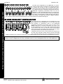
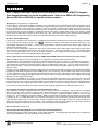
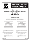
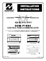
GEM-P1664
CONTROL PANEL/COMMUNICATOR
For use with "Classic" keypads (GEM-RP1CAe2, GEM-RP2ASe2, GEM-RP3DGTL and GEM-RP4RFC/GEM-RP4C)
and with "K Series" keypads (GEM-K1CA, GEM-K2AS, GEM-K3DGTL, and GEM-K4RF/GEM-K4)
GEMINI
SYSTEM READY
09/01/05
12:00 AM
ARM
ED
GEMINI
TUS
ST A
R
1
B
4
C
7
2
5
8
6
S
ATU
D ST
ME
AR
NEXT/YES
U
3
P
R
A
PRIOR/NO
Q
SYSTEM ARMED
AC ON
READY
01/01/97
12:00AM
READY
AC ON
NEXT/YES
123
B456
AREA
9 0 G
D
E
PRIOR/NO
F
AREA
C7 8 9 0 G
COMPUTERIZED SECURITY SYSTEM
C O M P UT E R I ZE D S E C U R I T Y S Y S T E M
R
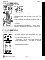
"K Series" GEM-K1CA
GEMINI
32
A
ED
RM
"K Series" GEM-K2AS
SYSTEM ARMED
01/01/97 12:00AM
ENT A1
INTERIOR
BYPASS
FIRE/TBL
SYS TBL
TUS
STA
CHIME
NEXT/YES
R
A
123
B456
D
E
PRIOR/NO
F
AREA
C7 8 9 0 G
COMPUTERIZED SECURITY SYSTEM
R
"K Series" GEM-K3DGTL
© NAPCO 2006
"K Series" GEM-K4RF
WI1424A 1/06
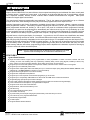
THIS MANUAL INCLUDES FEATURES WHICH ARE ONLY AVAILABLE IN
GEM-P1664 CONTROL PANEL FIRMWARE VERSION 1.0 OR LATER.
IMPORTANT NOTICE
GEM-P1664 panel version 01 requires the use of the following version keypads:
•
GEM-RP1CAe2 Version 9A, GEM-K1CA Version 9A
•
GEM-RP2ASe2, Version 7, GEM-K2AS, Version 7
•
GEM-RP3DGTL, Version 3, GEM-K3DGTL, Version 3
•
GEM-RP4RF, Version 2, GEM-K4/K4RF, Version 2
Upon entering program mode, the keypad display will flash the control panel firmware version, followed by the keypad firmware
version:
GEM-RP1CAe2: [019A], GEM-RP2ASe2: [0107], GEM-RP3DGTL: [0103], GEM-RP4RF: [0102]
GEM-K1CA: [019A], GEM-K2AS: [0107], GEM-K3DGTL: [0103], GEM-K4/K4RF: [0102]
For consistency, it is recommended that all keypads either be all "classic" (such as the GEM-RP1CAe2 keypad) or all "K Series" (such as the GEM-K1CA)--both keypad types should not be used in one alarm system.
CHANGES FROM PREVIOUS EDITION
The following changes have been made to this manual (WI1424A) since the previous edition (WI1424):
Page 6: Specifications: Current ratings updated.
Page 59: Wiring Diagram updated.
Refer to accompanying GEM-P1664 Programming Instructions (WI1422 and WI1423) for programming information.
NAPCO Security Systems, Inc.
333 Bayview Avenue, Amityville, New York 11701
For Sales and Repairs, call toll free: (800) 645-9445
For direct line to Technical Service, call toll free: (800) 645-9440
Internet: http://www.napcosecurity.com
WI1424A 1/06
Page 3
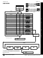
TABLE OF CONTENTS
INTRODUCTION..................................................... 4
BASIC OPERATION ...............................................20
General Description ................................................ 4
User Codes & Zone Descriptions .............................20
Features .................................................................. 4
Arming and Disarming the System ...........................21
Specifications .......................................................... 6
Bypassing Zones .....................................................23
Ordering Information ............................................... 7
Unbypassing Zones .................................................23
Summary of UL Requirements ................................ 8
Alarm Indication .......................................................23
Function Mode/Dealer Program Mode .....................23
INSTALLATION ...................................................... 9
Mounting ................................................................. 9
KEYPAD MESSAGES .............................................26
Wiring...................................................................... 10
GLOSSARY ............................................................27
Wireless Systems.................................................... 10
Typical Residential Fire Installation ......................... 10
Typical Partitioned Installation ................................. 10
TESTING THE SYSTEM ......................................... 11
STANDBY-BATTERY CALCULATION WORKSHEET
................................................................................46
WIRING LEGEND ...................................................47
KEYPAD PROGRAMMING MODES .......................48
Function Mode .........................................................48
Dealer Mode ............................................................49
WIRING CONNECTIONS ....................................... 12
Battery .................................................................... 12
Transformer ............................................................ 12
Siren/Bell Output ..................................................... 12
Auxiliary Power ....................................................... 12
PGM Outputs .......................................................... 12
Remote Bus ............................................................ 13
Earth Ground .......................................................... 13
Zone Configuration Styles ....................................... 14
Easy Menu Mode .....................................................50
User Mode ...............................................................51
Keypad Configuration Mode.....................................52
CP-01 QUICK REFERENCE CHART ......................53
FACTORY DEFAULT DESCRIPTION .....................55
FCC STATEMENT ..................................................57
GEM-P1664 WIRING DIAGRAM .............................59
LIMITED WARRANTY .............................................60
Basic Zone Configuration ................................... 14
EZ Zone Doubling Configuration ........................ 14
Zone Expansion Device Compatibility ..................... 15
4-Wire Smoke Detectors ......................................... 15
2-Wire Smoke Detectors ......................................... 15
Telephone Lines...................................................... 16
KEYPAD CONFIGURATION MODE ....................... 17
Keypad Installation .................................................. 17
Configuring the Keypads ......................................... 17
L
NAPCO Security Systems
X
GEM-P1664 Installation Instructions
Page 4
WI1424A 1/06
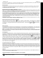
INTRODUCTION
GENERAL DESCRIPTION
Napco's Gemini GEM-P1664 is a state-of-the-art microcomputer-based burglary and residential fire alarm control panel
of modular design. Integrally an 8-zone panel, it will support up to 64 zones with the use of zone doubling, optional
zone expansion modules, wireless receiver modules and/or GEM-RP1CAe2/GEM-K1CA Keypads. Each panel
includes an integral digital communicator.
The control panel features programmable area partitioning. That is, the system may be divided into up to 4 discrete
multiple-zone areas, each allowing access by only those users programmed for their respective area.
Opening Suppression and Closing Suppression, available through Napco Quickloader software, suppress reporting
within programmed “windows”. Conversely, Exception Reporting can transmit a “fail to close” if the panel is not armed
within programmed intervals and, similarly, a “fail to open” if the panel is not disarmed within programmed intervals.
Furthermore, the panel can be programmed to automatically arm either area at any time. A log containing up to 400
events (accessible through QuickloaderTM software) monitors control-panel activity referenced to a precision real-time
clock. A detailed event history may be displayed at the computer, using Napco’s PCD-Windows Quickloader Software.
Keypads feature a liquid-crystal display for messages. In normal use, the LCD shows zone identification and status
messages, and the log can also be viewed. Conventional LEDs and a sounder are also provided for annunciation.
Data may be quickly and easily downloaded to the control panel using a PC-compatible computer with Napco's PCDWindows Quickloader software and PCI2000 computer interface. Or, the panel may be programmed using the keypad
in its secondary mode of operation. In the keypad programming modes (there are two: Dealer and User), the LCD
shows memory address, data values, programming prompts, and the alphanumeric characters required for entering up
to 64 user codes and custom zone descriptions.
Features
NOTE: Failure to install and program as described in this manual for UL-listed
systems voids the listing mark of Underwriters Laboratories, Inc.
FEATURES
Control Panel Features
Eight
end-of-line-resistor burglary zones programmable for Area (expandable to sixteen end-of-line resistors with zone
doubling or series zone doubling with loop supervision), Exit/Entry Delay, Interior (Stay) Bypass, Exit/Entry Follower, Day
Zone, Chime, Fire options, Swinger Shutdown, Zone Anding and a variety of other features.
Supports up to 64 zones with optional zone-expansion modules, wireless receiver modules and 4-zone keypads.
Supports up to 64 individually coded users.
Supports three outputs (Bell, PGM1 and PGM2) and up to 16 external outputs (using Relay Module RB3008, RM3008 or the
GEM-OUT8. See Relay Control in glossary for more information).
Supports three keypad panics: Fire, Police & Auxiliary.
Supports four independent area partitions.
Supports up to seven separate access stations (keypads) by up to 64 users.
Supports up to 16 separately-addressable X-10 devices with the GEM-X10 KIT and PC04 interfaces.
English-language prompts & system status messages.
User Codes and Zone Descriptions outside assigned areas are able to be blocked from keypad display.
User-customized zone descriptions, re-programmable as required.
Supports 2-wire and 4-wire smoke detectors.
Reports alarms, restores and troubles by zone.
400 Event Log.
Two programmable entry delay times.
One Interior Zone Group.
Dynamic battery test interrupts charging and places battery under load every four hours.
Two Chimes by zone; programmable duration.
Quickloader programmable.
2 PGM outputs.
Supports Gemini Wireless Devices.
X
GEM-P1664 Installation Instructions
L
NAPCO Security Systems
WI1424A 1/06
Page 5
Communicator Features
Compatible with all major receiver formats, including 4/2, SIA and Point ID (except Radionics Modem II).
Rotary dial and TouchToneTM with Rotary backup.
Three 20-digit telephone numbers.
Backup Reporting; Double Reporting; Split Reporting.
64 User Codes with Opening/Closing -Reporting by user.
AC Failure Reporting with programmable report delay.
Supervised telephone line with a fixed 60 second delay.
Pager capability.
Keypad Features
English-language LCD display; LED and sounder annunciators.
Supports up to seven 4-wire keypads.
Provisions for fire, police and auxiliary panic alarms.
Integral 4-zone EZM included in each keypad (GEM-RP1CAe2/GEM-K1CA only).
Fault-Find diagnostics simplify troubleshooting.
SIA CP-01 Features.
See
page 59 for complete information regarding how the Factory Program complies with the Security Industry Association
False Alarm Reduction Control Panel-01 Standard (SIA FAR CP-01).
Features
IMPORTANT NOTE
This manual supports the keypad programming of the GEM-P1664 control panel with the NAPCO "classic" GEMRP1CAe2, GEM-RP2ASe2, and GEM-RP3DGTL keypads as well as the GEM-K1CA, GEM-K2AS, and GEM-K3DGTL
"K Series" keypads. The new "K Series" models offer the new STAY and AWAY buttons with simplified functionality,
along with the new MENU and ENTER buttons.
While the instructions in this manual are depicted using the GEM-K1CA and GEM-K2AS keypads, the manual applies to
both the "classic" and the "K Series" keypads.
Program Mode is the same for both keypads--only the button names have changed, as follows:
• The A button and the R button operate identically (in Program Mode) for both keypads.
• The
D button and the U button operate identically (in Program Mode) for both keypads.
button and the
button operate identically (in Program Mode) for both keypads. The words
• The
"NEXT/YES button" are used in this manual.
button and the
button operate identically (in Program Mode) for both keypads. The words
• The
"PRIOR/NO button" are used in this manual.
L
NAPCO Security Systems
X
GEM-P1664 Installation Instructions
Page 6
WI1424A 1/06
SPECIFICATIONS
GEM-P1664
Operating Temperature: 0-49°C (32-120°F)
Input Power: 16.5-18.0 VAC via CLASS 2 Plug-In 20VA, 40VA or 50VA Transformer
Loop Voltage: 10-13Vdc
Loop Current: 3mA without Zone Doubling, 2.4mA with Zone Doubling using a 2.2K Ohm end-of-line resistor (Model EOL2.2K);
5mA for 2-wire smoke-detector zones; 1.4 mA using a 3.9K Ohm resistor (Model EOL3.9K) with Zone Doubling; 3mA with Series Zone with Loop Supervision and 3mA with Series Zone Doubling with Loop Supervision
Loop Resistance: 300 Ohm max.; 50 Ohm for 2-wire smoke-detector zones
Alarm Voltage Output: 1
Programmable Negative Outputs: 2
Auxiliary Power Output: 11.7-12.5 VDC
Remote Power Output: 12 VDC regulated (for keypads)
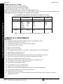
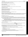
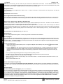
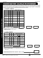
Combined Standby Current (Remote Power + Aux. Power + Fire Power): See following charts.
RESIDENTIAL BURGLARY & COMMERCIAL BURGLARY**
16.5VAC
TRANSFORMER
BATTERY
(12 VDC)
STANDBY
CURRENT
ALARM
CURRENT
STANDBY
TIME
40VA/50VA
7 AH
550 mA
550 mA(1)
4 Hours
20VA*
7 AH
500 mA
2.0 A
4 Hours
20VA*
7 AH
500 mA
2.0 A
6 Hours
Specifications
COMBINATION RESIDENTIAL FIRE & RESIDENTIAL BURGLARY
16.5VAC
TRANSFORMER
BATTERY
(12 VDC)
STANDBY
CURRENT
40VA/50VA
7 AH
120 mA
40VA/50VA *
Two 7 AH
360 mA
ALARM
CURRENT
STANDBY
TIME
(1)
24 Hours
(1)
24 Hours
(1)
24 Hours
(1)
24 Hours
520 mA
280 mA
20VA *
7 AH
120 mA
360 mA
20VA *
Two 7 AH
360 mA
120 mA
NOTE: (1) Alarm current can be increased by reducing standby current by the same amount.
* Not evaluated by UL.
** Commercial Burglary specifications not evaluated by UL.
FOR ALL UL INSTALLATIONS
"ENABLE RESIDENTIAL FIRE" (ADDRESS 1422) MUST BE PROGRAMMED
The feature "Enable Residential Fire" (address 1422, option 4 / bit 3) must be programmed for ALL UL installations.
To program, please refer to the GEM-P1664 Programming Instructions (WI1422 and WI1423) for further information.
EZM Module: GEM-EZM816: Input, 50mA
Keypad Current: GEM-RP1CAe2: 100mA; 35mA if back lighting is disabled (cut W1, W2 & W3).
PGM Output: 5mA, 12V Special Application
Maximum Number of Keypads: 7
Maximum Wiring Length for each run (#22AWG): 1000' divided by total number of keypads and
EZMs on run
Keypad Dimensions: 4” x 5” x 1” (HWD); 11.1cm x 14.9cm x 2.7cm (HWD)
X
GEM-P1664 Installation Instructions
L
NAPCO Security Systems
WI1424A 1/06
ORDERING INFORMATION
System Components
GEM-P1664: Residential UL-Listed Burg and Fire
Control Panel.
GEM-RP1CAe2: 32-Character LCD Burg & Fire Keypad
with 4 EOL Zones.
GEM-RP2ASe2: LCD Burg & Fire Keypad with remote
panic.
GEM-RP3DGTL: Burg & Fire Keypad.
GEM-RP4RFC: Digital Icon Burg & Fire Keypad with
Integral RF Receiver.
GEM-RP4C: Digital Icon Burg & Fire Keypad.
GEM-K1CA: 32-Character LCD Burg & Fire Keypad with
4 EOL Zones.
GEM-K2AS: LCD Burg & Fire Keypad with remote
panic.
GEM-K3DGTL: Burg & Fire Keypad.
GEM-K4RF: Digital Icon Burg & Fire Keypad with Integral RF Receiver.
GEM-K4: Digital Icon Burg & Fire Keypad.
GEM-EZM8: 8 Zone Expansion Zone Module
GEM-EZM816: 4-16 Zone Expansion Zone Module
GEM-EVA 1: Electronic Voice Annunciator
GEM-RECV8: Wireless Receiver, 8 Zones
GEM-RECV16: Wireless Receiver, 32 Zones
GEM-RECV96: Wireless Receiver, 64 Zones
GEM-TRANS2: Window/Door Transmitter, 2-Point
GEM-RTRANS: Recessed Window/Door Transmitter
GEM-KEYF: Key Fob Transmitter
GEM-SMK: Wireless Smoke Detector
GEM-PIR: Wireless PIR
GEM-PIRPET: Wireless Pet Immune Transmitter*
GEM-RS232: Isolated Comuter Interface
GEM-DT: Wireless Dual-Technology Sensor
GEM-GB: Wireless Glass-Break Detector*
GEM-X10KIT: X-10 Interface*
GEM-OUT8: 8 output active low output module
GEM-TEMP64: GEM-P1664 indoor/outdoor programmable temperature sensor*
RM3008: Relay Module (in enclosure)
M278: Line-Reversal Module
PS3002: Power-Supply Module, 13.2Vdc, 1.9A*
EOL2.2K: End-of-Line Resistor Assy., 2.2k Ohm
EOL3.9K: End-of-Line Resistor Assy., 3.9k Ohm for
Zone Doubling
EOL4.7K: End-of-Line Resistor Assy., 4.7k Ohm
FT2200: End-of-Line Relay/Resistor Supervisory Module
RB1000: Relay Board, single output*
RBATH1: Dual Battery Harness
RPB-3: Universal Keypad Mounting Box
TRF11: Transformer, 16.5Vac/40VA, Class 2
TRF14: Transformer, 16.5Vac/50VA, Class 2
WL1: Wire Assembly with Lug Connector, 20”
L
NAPCO Security Systems
VERI-PHONE: Two-Way Voice/Listen-In Module
PCD-Windows: Downloading Software (for Windows)
for IBM PC-Compatible, V5.0 or greater
PCI2000/3000: Software Interface for IBM PCCompatible Computer*
PCI-MINI: Notebook Computer Interface*
W834-1: Keypad Cable, plug-in (20”)
OI193: User Guide, GEM-RP1CAe2
OI192: User Guide, GEM-RP2ASe2
OI249: User Guide, GEM-RP3DGTL
OI278: User Guide, GEM-RP4C & RP4RFC
WI1212: Installation Manual, GEM-RP4C
WI1128: Installation Manual, GEM-RP4RFC
OI279: User Guide, GEM-K1CA
OI280: User Guide, GEM-K2AS
OI281: User Guide, GEM-K3DGTL
OI283: User Guide, GEM-K4 & K4RF
WI1178: Installation Manual, GEM-K4
WI1179: Installation Manual, GEM-K4RF
WI1422: GEM-P1664 Programming Instructions (using
GEM-RP1CAe2 / GEM-K1CA keypads).
WI1423: GEM-P1664 Programming Instructions (using
GEM-RP2ASe2 / GEM-K2AS or GEM-RP3DGTL /
GEM-K3DGTL keypads).
WI1424: GEM-P1664 Installation Instructions
WIZARD IIe: Telephone Interface Module*
*Not Investigated by UL
UL Listings
Household Burglar Alarm System Units: UL1023
Household Fire Warning System Units: UL985
Security Industry Association (SIA) False Alarm Reduction
Standard CP-01
** Pending
Napco Group Europe Ltd.
Libra Wireless Transmitters and Receivers for connection to Napco Intruder Control Panels (Operates on
433MHz, European Approved Frequency)
WI925: LIBRA-RECVXP-433 Wireless 8 Zone Receiver
WI924: LIBRA-RECV8-433, LIBRA-REC16433, LIBRAREC96433, Wireless 8/16/96 Zone Receiver
WI923: LIBRA-TRANS433, Wireless Door Contact
WI929: LIBRA-PIR433, Wireless PIR
WI931: LIBRA-KEYF433, Wireless KeyFob
WI930: LIBRA-SMK433, Wireless Smoke Detector
WI928: LIBRA-GB433, Wireless Glass Break Sensor
X
GEM-P1664 Installation Instructions
Ordering Information
Optional Accessories and Peripherals
Page 7
Page 8
WI1424A 1/06
Smoke Detectors, 4-Wire:
1. ESL 445AT, 445C, 445CT, 445CR, 445CRT
2. Hochiki America SLG-12 with YBC-RL4-RA Base
3. System Sensor 2312/24T; 1412; 1412TH; 2412TH
Subtract total smoke-detector alarm current from available standby current.
Note: Any normally-open devices that do not require power from the control panel, such as pull stations and
thermostats may be used if acceptable to the Authority having Jurisdiction.
Smoke detectors & Summary of UL Requirements
UL Compatible Smoke Detectors (Providing UL Recognition or Listing)
Manufacturer
4-Wire
Smoke Detector
2-Wire
Smoke Detector *
Napco
FW-4
FW-2
Sentrol
449AT
449C
449CRT
449CST
449CSRT
449CSRH
449CSST
449CLT
449CSLT
449CTE
741U
742U
712U
722U
732U
711U
721U
721UT
731U
System
Sensor
1112
2112
2112T
2112TSRB
2100
2100T
1100
Smoke Detector
Base
701U
702U
702RE
702RU
Note: * Voltage Rating: 8.5-13.3 VDC, Maximum Number of Detectors: 10
SUMMARY OF UL REQUIREMENTS
Residential
Recognized Limited-Energy Cable for initiating, indicating and supplementary circuits.
Initiating loops supervised if longer than 3 feet
FT2200 End-of-Line Relay for Fire (if using 4-wire smoke detectors)
Minimum alarm timeout of 5 minutes
Maximum exit time: 60 seconds
Maximum entry time: 45 seconds
Do not program “Swinger Shutdown”, “Force Arming”, “Selective Bypass” or “50 ms Loop Response”
“Abort Delay” may not exceed 45 seconds
Program “Disable Callback Download”
Automatic dialer may not dial a police station number that has not been dedicated for such service
System must be tested at least weekly under AC/battery and Battery-Only conditions
Replace the rechargeable battery at least every 5 years
If the battery is heavily discharged, replace it or have it tested by a qualified technician
For silent panic, connect only to UL-listed holdup devices
All zones must be programmed for “Priority”
Do not program any zones for “Keyswitch Arming”
System must be serviced at least once every year
Residential Fire and Combination Residential Fire & Burglary must program “Residential Fire”
Keypad Expansion (EZM) Zones are not to be used as fire zones
Keypad Auxiliary is not to be selected
The GEM-K Series Keypads must have the indicators printed on the face label (Fire, Police and Auxiliary) covered by a
supplied label if not in use.
X
GEM-P1664 Installation Instructions
L
NAPCO Security Systems
WI1424A 1/06
Page 9
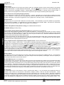
INSTALLATION
CAUTION: This equipment generates and uses radio-frequency energy. If not installed using conventional installation
practices for RF devices, it may cause interference to radio and television reception. It has been tested and found to
comply with the limits for a Class A computing device pursuant to Subpart B of Part 15 of FCC Rules, which are
designed to provide reasonable protection against such interference. However, there is no guarantee that
interference will not occur in a particular installation. If it has been found to cause interference to radio or television
reception, which can be determined by removing and reapplying AC and battery power to the equipment, the installer
should try to correct the interference by one or more of the following measures: reorient the receiving antenna;
connect the power transformer to a different outlet so that the control panel and receiver are on different branch
circuits; relocate the control panel with respect to the receiver.
MOUNTING
Control Panel
Choose a mounting location accessible to (a) a continuously-powered AC source, (b) system ground, a steel or copper
ground rod, ideally no further away than 10 feet, and (c) telephone lines (keep telephone wiring away from keypad
wires). Remove appropriate knockouts for cables. Place the control panel at a convenient viewing height and mark
the mounting holes. Attach the enclosure using screws suitable for the mounting surface.
Grounding
Keypad
A keypad should be located near each exit/entry door. The keypad features a handy pull-up reference label. Before
mounting the keypad onto the wall, push the Sliding Label Plate (with label and felt backing affixed and handle facing
forward) down the guides at the rear of the keypad until it snaps into place. Once installed, the Sliding Label Plate
cannot be removed without first removing the keypad from the wall. Note: (1) The keypad fire and panic keys should
not be considered a substitute for a listed manual initiating device, such as a pull box. (2) Each GEM-RP1CAe2
includes provisions for four additional zones. See ADDING EXPANSION ZONES.
If installing onto a double-gang box, insert mounting screws through the two vertical elongated holes on the left side of
the case and into the box. If the box is visible when viewed from the front, adjust the keypad vertically and tighten the
screws. Then, using hardware suitable for the mounting surface, add one or two screws at the right side of the keypad
case directly into the wall to ensure a secure installation. Note: Do not overtighten the screws! Uneven walls may
cause the keypad case to distort.
L
NAPCO Security Systems
X
GEM-P1664 Installation Instructions
Mounting
Connect the control-panel grounding screw to a metal cold-water pipe or a long steel (or copper) ground rod driven
deeply into the earth. Do not use a gas pipe, plastic pipe or AC ground connections. Use at least 16-gauge wire.
Make the run as short and direct as possible, without any sharp bends in the wire.
Page 10
WI1424A 1/06
Wiring
Wire keypad(s), zones, expansion zone modules and output devices as shown on the Wiring Diagram. Note that the
Wiring Diagram contains important information not available elsewhere in this manual.
CAUTION: Do not run telephone wiring near speaker wires; do not run keypad wiring with loop wiring.
Adding Expansion Zones
GEM-P1664 control panel can support up to 16 zones as is, however this number may be increased to as many as 64
programmable zones using optional expansion zone modules (EZMs).
Wireless Systems
With the addition of at least one GEM-RECV series receiver, the GEM-P1664 will support up to 64 wireless
transmitters. The panel can accommodate one or two receivers within the premises, responding to the one with the
stronger transmitter signal. If any transmitters are selected for the default program, a GEM-RECV receiver will
automatically be programmed.
The keypad can display the status of any transmitter, indicating the condition of the zone (normal or open) and
transmitter troubles (low battery, tamper or supervisory failure), and signal strength of the last transmission. A receiver
failure will be indicated by “E06-NN” (“no response”, with NN representing the receiver number).
Wiring
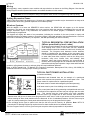
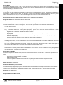
TYPICAL RESIDENTIAL FIRE INSTALLATION
(Where permitted by local codes)
At least one smoke detector should be installed directly outside
each sleeping area. If there is more than one floor, additional
smoke detectors should be installed on each level, including the
basement. The living-area and basement smoke detectors
should be installed near the stairway of the next upper level.
For increased protection, additional detectors should be installed
in areas other than those required, such as the dining room,
bedrooms, utility room, furnace room, and hallways. Heat
detectors, rather than smoke detectors, are recommended in
kitchens, attics, and garages due to conditions that may result in
false alarms and improper operation. Large areas and areas with
partitions, ceiling beams, doorways, and open joists will require additional detectors.
Refer to NFPA Standard No. 74 (National Fire Protection Association, Batterymarch Park, Quincy, MA 02269) for
additional information, including proper mounting of detectors.
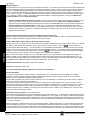
TYPICAL PARTITIONED INSTALLATION
(4 Partitions Available)
Described
and illustrated here are an example of a partitioned
system with common-area protection of the control-panel room. This
system meets UL requirements for a partitioned system.
All areas must be owned and managed by the same person(s).
All areas must be part of one building at one street address.
The control panel and all wiring protecting each partitioned area must
be confined to the respective area and may not impinge upon the other
area. This requires that the control panel room have redundant
protection; that is (a) multiple sets of door contacts, each wired to a
separate zone and (b) one of those zones programmed for each area. In order to gain access to this protected area
without causing an alarm, both partitions must be disarmed. In lieu of redundant protection, 24-Hour Zones may be
used. Any zone protecting the control panel and transformer may not be programmed for bypass.
The
sounding device must be placed such that the bell test can be heard by all partitions. Note: NFPA 74
(Household Fire Warning Equipment) requires that a fire alarm audible device be installed indoors.
The User Program Code is not to be given to anyone except the authority responsible for all partitions.
X
GEM-P1664 Installation Instructions
L
NAPCO Security Systems
WI1424A 1/06
Page 11
TESTING THE SYSTEM
After installation is completed, test the system as follows.
1. Call the central station to inform them of the test.
2. Initiate an alarm, preferably on a zone that activates a steady siren, and verify proper signalling.
3. Call the central station to confirm their receipt of a good transmission.
Note: Be sure to test all enabled keypad panics.
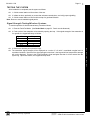
Signal Strength Testing/Wireless Systems
To test the operation of wireless transmitters, proceed as follows.
L
2. Fault a point of the transmitter to be tested by opening the loop. If the signal strength of the transmitter is
3 or greater, the keypad will beep, as follows:
Signal Power
Beeps
0-2
3
4-5
6-7
8-10
0
1
2
3
4
3. Restore the wireless point (close the loop).
The transmitter signal strength will be displayed on a scale of 3-10 with 3 considered marginal and 10
considered excellent. Note that if the signal strength is less than 3, the keypad will not beep and the strength
will not be displayed. Except in the Fault-Find Mode, signal strengths less than 3 will be entered into the
system log. Upon zone restore, the keypad will beep once.
NAPCO Security Systems
X
GEM-P1664 Installation Instructions
Testing the System
1. Enter the Fault-Find Mode. (See Dealer Mode on page 52. Panel must be disarmed).
Page 12
WI1424A 1/06
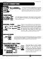
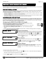
WIRING CONNECTIONS
Wiring Connections: Battery, Transformer, Siren Power, Aux. Power & PGM Outputs
BATTERY
The RED (+) and BLACK (-) flying leads must be connected
to a 12VDC 4-7 AH Rechargeable Battery, to serve as
backup power in the event of AC Power Failure. NOTE: To
calculate the available standby time refer to the StandbyBattery Calculation Worksheet at the back of this manual.
7
TRANSFORMER
(The following applies to installations in the United States of America): Connect
a 16.5 VAC Transformer to Terminals 1 and 2, using a wire of #18 AWG. or
larger at a distance of 15 ft. or less from the control panel. NOTE: Do not
connect to a switched outlet.
SIREN/BELL POWER
Connect the alarm sounding devices (self-contained sirens,
speakers or a mechanical bell) to Terminals 3 and 4. Any selfcontained siren requiring a 12 VDC input can be connected.
When connecting a mechanical bell, it must be supervised
using a 2.2k Ohm resistor. To connect 8 Ohm Speakers use a
Siren Driver with the proper polarity observed. NOTE: Refer to
the GEM-P1664 Wiring Diagram for alarm current
specification. Note: In NFPA Household Fire Installations.
only a single siren or bell can be used on this bell circuit.
AUXILIARY POWER
Connect the auxiliary devices (motion detectors, glass breaks, etc.) to Terminals 5
and 6. Auxiliary Power provides 11.7-12.5 VDC nominal output which is used for
powering auxiliary devices. NOTE: To calculate the available standby time refer to
the Standby-Battery Calculation Worksheet at the back of this manual.
PGM OUTPUTS (PGM1 & PGM2)
PGM1 and PGM2 are negative switched
programmable outputs that can be activated
depending on the programming options
selected (see GEM-P1664 Programming
Instructions). Connect the device controlled by
the programmable output between terminal 5
(+) and the PGM output (-), either terminal 7 or
8. As an example, the connection to the
RB1000 Relay Module is shown.
X
GEM-P1664 Installation Instructions
L
NAPCO Security Systems
WI1424A 1/06
Page 13
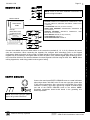
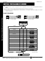
REMOTE BUS
NOTE: Refer to the EZM Installation Instructions for
specific wiring information.
REMOTE BUS
AVAILABLE DEVICES
ADDITIONAL
EZMs
1.
2.
3.
4.
5.
6.
7.
AVAILABLE DEVICES
1. KEYPADS: GEM-RP1CAe2, GEM-RP2ASe2, GEM-RP3DGTL, GEMKEYPADS: GEM-RP2AS & GEM-RP1CAe2
X-10 INTERFACE: GEM-X10
RP4 series, GEM-K1CA, GEM-K2AS, GEM-K3DGTL, GEM-K4 series,
W IRED ZONE EXPANDER: GEM-EZM816
(7 maximum)
W IRELESS RECEIVERS: GEM-RECV8, GEM-RECV16 & GEM-RECV96
RELAY MODULE: RM3008
2. X-10 INTERFACE: GEM-X10 (16 devices maximum)
VOICE INTERFACE: GEM-EVA
3. WIRED ZONE EXPANDER: GEM-EZM4/8EX, GEM-EZM4/8 (64
TELEPHONE INTERFACE: W IZARD2
Example:
AR
ME
D
ST
AT
US
zones maximum)
4. WIRELESS RECEIVERS: GEM-RECV8, GEM-RECV16,
RECV96 (64 zones maximum)
5. RELAY MODULE: RM3008 (16 relays maximum)
6. VOICE INTERFACE: GEM-EVA 1
7. TELEPHONE INTERFACE: WIZARD IIe
GEM-
Connect the available devices as shown above to the remote bus terminals (9, 10, 11 & 12). Observe the correct
color wire connections. When connecting the keypads, first configure them accordingly (refer to the Keypad
Configuration Mode at the back of this manual). Keypads should be located near every exit/entry door. Up to seven
keypads may be connected if the longest cable run from the panel, to the farthest keypad (daisy chained or homerun) is less than 1000 feet. The maximum distance for seven keypads is 300 feet using 22 AWG. wire. NOTE: When
running keypad wire, avoid wiring parallel to other types of wiring.
EARTH GROUND
Connect the control panel EARTH GROUND screw to a metal cold-water
pipe using at least a #16 AWG. wire. Do not use a gas pipe, plastic pipe
or AC ground connections. Also, connect the circuit board to the metal
enclosure. Connect a wire with a ground lug crimped or soldered onto
one end of the EARTH GROUND screw to the cabinet. NOTE:
Grounding connections should avoid bends in the grounding wire
whenever possible.
NOTE: Do not use a gas pipe, plastic
pipe or AC ground connections.
L
NAPCO Security Systems
X
GEM-P1664 Installation Instructions
Wiring Connections: Remote Bus & Earth Ground
(GEM-RP1CAe2)
2 LINE KEYPAD
Page 14
WI1424A 1/06
Wiring Connections: Basic Zone Configuration & EZ Zone Doubling Configuration
BASIC ZONE CONFIGURATION
The basic zone configuration for the GEM-P1664 is 8 zones.
Connect as shown above to terminals 13-24. Normally Closed (N.
C.) devices may be wired in series or Normally Open (N.O.)
(–)
devices may be wired in parallel. Use the 2.2K Ohm end-of-line (E.
O.L.) resistor in each zone, if selected in programming (refer to the
GEM-P1664 Programming Instructions). Zones 1-8 can be
selected for a “Fast Loop Response (50 ms)” or a “Normal Loop
Response (750 ms)”. Other zone options include Zone Type (Entry/
Exit, Interior, 24 Hour Protection, Trouble and Fire), Instant, Chime,
Area Selection and PGM Output selection. Additional expansion
zone modules or wireless sensor transmitters/receivers can be used to obtain zones numbered 9 through 32.
EZ ZONE DOUBLING TM CONFIGURATION
The control panel zone configuration may be expanded from 8 to 16
zones without the use of EZM Modules. To do so simply select “EZ
Zone Doubling” in programming (refer to the GEM-P1664
Programming Instructions) and connect zones as shown above.
NOTE: If both zones in a zone-pair configuration (ex: zones 1 & 9 in
the above diagrams) are to be used, then normally closed devices
must be wired to both zones. The 3.9K EOL resistor must be placed
at the end of the loop of the higher zone and the 2.2K EOL resistor
must be placed at the end of the loop of the lower zone.
If Normally open zones for fire or panic devices are required, then
the lower zone (2.2K EOL resistor) must be used and the higher
zone (3.9K EOL resistor) must not be programmed for any area.
Additional expansion zone modules or wireless sensor transmitters/receivers can be used to obtain zones numbered 9 through 32
WARNING: Assigning a fire zone or keyswitch zones to a zone doubled will disable the respective complimentary zone. For
example, if zone 8 is assigned as a fire zone, it will disable zone 16. If zone 3 is assigned as a fire zone, it will disable zone 11.
X
GEM-P1664 Installation Instructions
L
NAPCO Security Systems
WI1424A 1/06
Page 15
4-WIRE SMOKE DETECTORS
4-WIRE SMOKE DETECTOR WIRING
Four wire smoke detectors may be connected to any programmed fire zone (1-8)
as shown, within the panel. If the Zone Doubling is used (see EZ Zone Doubling
Configuration), the respective complementary zones (9-16) are disabled when 4wire smoke detectors are connected to zones 1-8. If external EZMs are used for
zones 9-64, then 4-wire smoke detectors may be connected to any programmed
fire zones (9-64).
Power must be obtained from terminal 25 and 6. If Fire Alarm Verification is
desired to reset the smoke detectors, select this option for the desired fire zone.
2-WIRE SMOKE DETECTORS
2 -W IR E S M O K E
D E T E C T O R W IR IN G
Two-wire smoke detectors can only be connected to zones 7 and 8. To use
them, select fire zone programming option and select 2-wire smoke detector
programming option for the desired fire zone 7 or 8 (refer to the GEM-P1664
Programming Instructions) and set JP3 to the “2-WF” position as shown.
Connect the 2-wire smoke detectors as shown.
If the Zone Doubling is used (see EZ Zone Doubling Configuration), the
respective complementary zones (15 & 16) are disabled when 2-wire smoke
detectors are connected to zones 7 & 8.
If Fire Alarm Verification is desired to reset the smoke detectors, select this
option for the desired fire zone (zone 7 or 8).
L
NAPCO Security Systems
X
GEM-P1664 Installation Instructions
Wiring Connections: 4-Wire Smoke Detectors & 2-Wire Smoke Detectors
The GEM-P1664 can use conventional 12 VDC 4-wire smoke detectors. To use
them, select fire zone programming option and do not select 2-wire smoke
detector programming option for the desired fire zone (refer to the GEM-P1664
Programming Instructions). Set JP3 to the position as shown, if zones 7 or 8 are
to be used.
Page 16
WI1424A 1/06
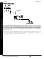
TELEPHONE LINES
RING
TIP
RING
TIP
Model 368 Cord
Wiring Connections: Telephone Lines
RING
TIP
Connect the Model 368 Cord as follows: 26 (RED = Telco Ring), 27 (GREEN = Telco Tip), 28 (GRAY = Home Ring)
and 29 (BROWN = Home Tip). Insert the modular plug into an approved USOCRJ31X jack (or a CA31A jack for
Canadian installations). The Telco Line is used by the control panel to dial the central station and for downloading.
This line should not be connected to party lines or coin operated telephones. If connected to a line with call waiting,
then call waiting interrupt numbers must be programmed into the CS Telephone Numbers (refer to the GEM-P1664
Programming Instructions).
When communicating to central station and during downloading, the control panel seizes the telephone lines from the
house phones, rendering them inoperative during communication.
Upon completion of central station
communication, the telephone line is restored to the house phones.
X
GEM-P1664 Installation Instructions
L
NAPCO Security Systems
WI1424A 1/06
Page 17
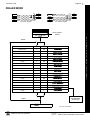
KEYPAD CONFIGURATION MODE
This section will focus on configuring the GEM-RP1CAe2/GEM-K1CA and GEM-RP2ASe2/GEM-K2AS Keypads. We recommend
that either a GEM-RP1CAe2 or a GEM-K1CA keypad be used for programming.
KEYPAD INSTALLATION
Each keypad must be assigned an address number (1–7) and each requires its own configuration procedure (see CONFIGURING
THE KEYPADS, which follows, and DIRECT ADDRESS KEYPAD AREA OPTIONS). At least 1 keypad must be used; only 1 is
required for a single-area Commercial Burglary installation.
•
GEM-RP1CAe2/GEM-K1CA - is a 2-line combination fire/burglary/access keypad capable of supporting 4 EZM zones. A GEMRP1CAe2 or GEM-K1CA is recommended for use with programming.
•
GEM-RP2ASe2/GEM-K2AS - is a utility LCD keypad combining several preset LCD words with a limited message line. NOTE:
Due to space constraints, available messages are abbreviated and will scroll automatically.
CONFIGURING THE KEYPADS
A total of up to 7 keypads may be connected to the panel. GEM-RP1CAe2/GEM-K1CA and GEM-RP2ASe2/GEM-K2AS keypads may
be intermixed but require different configuration procedures, as described in the following paragraphs. If you have a GEM-K1CA keypad, please see the "Important Note" on page 5 regarding the differences between the GEM-RP1CAe2 and the GEM-K1CA keypad
buttons. The buttons displayed below will be for the GEM-K1CA keypad.
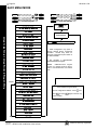
Each GEM-RP1CAe2/GEM-K1CA keypad must be configured for (a) keypad tactile beep; (b) entry
sounder; (c) keypad address; (d) EZM address; and (e) zone response.
NORMAL
To enter the GEM-RP1CAe2/GEM-K1CA Configuration Mode:
KEYPAD
1. Move jumper JP1 (located at the upper center of the control panel board) from Pins 1-2 (top two) to
CONFIGURE
Pins 2-3 (bottom two). NOTE: See the Wiring Diagram.
2. After about 15 seconds, the display will read “XX OUT OF SYSTEM”, where XX indicates the keypad
address.
3. Press 11123 R and proceed as follows. (Repeat the following procedure for all keypads.)
Keypad Tactile Beep
Keypad Beep
ON
Upon entering the Keypad Configuration Mode, “KEYPAD BEEP ON” will be displayed,
indicating that the tactile beep, which sounds when any button is pressed, is on.
To turn off the tactile beep, press the U or D button (the U or D button will
toggle the tactile beep on and off). Press the A or R button to continue
or press the C button to exit.
Entry Sounder
ON
Entry Sounder
To turn off the keypad sounder during entry time, press the U or D button (the
U or D button will toggle the entry sounder on and off).
R
Keypad Address
01
Press the A or
button to continue or press the C button to exit.
Keypad Address
If more than one keypad is installed, each must be assigned a unique keypad
address (that is, no two keypads may be numbered alike):
keypads
must be numbered consecutively (missing numbers are not
permitted)
To assign the keypad number, proceed as follows:
1. Enter the assigned keypad number 01–07, then press the U or D button to save. A valid number will be acknowledged by a
short beep; an invalid number will be rejected by a long beep.
2. Press the A or R button to continue or press the C button to exit.
L
NAPCO Security Systems
X
GEM-P1664 Installation Instructions
Keypad Configuration Mode
Configuring the GEM-RP1CAe2/GEM-K1CA Keypad
Page 18
New
Compat #
WI1424A 1/06
Compatibility Number (Not Applicable)
0000
THIS FEATURE IS NOT COMPATIBLE WITH THE GEM-P1664 CONTROL PANEL. DO NOT CHANGE THIS SETTING.
Press the A or R button to continue or press the C button to exit.
EZM Address
EZM Address
The keypad's internal EZM (Expansion Zone Module) may be utilized to
provide four additional wired zones. Whether used alone or in conjunction
with optional GEM-EZM series modules or other keypad EZMs, it must be
assigned a unique address (or Group number, see Keypad Programming
Workbook) similar to its keypad address. If no other EZMs are to be used,
designate the keypad as Group “01” at the “EZM ADDRESS 00” display. In multiple-EZM systems, enter an assigned
group number “01” through “14”. (Each EZM must have a unique assigned group number, starting with “01” and
proceeding consecutively.) Press the U or D button to save. Press the A or R button to continue or press the
00
Keypad Configuration Mode
C
button to exit.
Zone Response
Zone Response
00
The normal loop response of each keypad expansion zone is 750mS,
however the response time of any zone can be reduced to 50mS as
follows.
1. Of the following, circle the number(s) in parentheses associated with
the zone(s) to be changed:
Zone 1=(1); Zone 2=(2); Zone 3=(4); Zone 4=(8)
2. Add up the circled numbers.
3. At the keypad, enter the sum as a two-digit number “01” through “15” on the display, then press the U or D button.
Example. Change Zones 2, 3 and 4 to 50mS response.
1. Circle numbers for Zones 2, 3 and 4: (2), (4) and (8).
2. Add up the circled numbers: 2 + 4 + 8 = 14.
3. Enter “14” at the keypad, then press the U or D button.
Press the A or R button to continue or press the C button to exit.
Note: Panel Zone Response time can also be changed in Direct Address programming (first 8 zones only). See the
Programming Instructions WI1422 and WI1423 for more information.
Program Control
Message #
1
Program Control Message (Not Applicable)
THIS FEATURE IS NOT COMPATIBLE WITH THE GEM-P1664
CONTROL PANEL.
Press the R button to continue (the display will loop back through
selections, for changes) or press the C button to exit the Keypad Configuration Mode (display will read “01 OUT OF
SYSTEM”). Then replace Jumper JP1 across Pins 1–2 (top two).
X
GEM-P1664 Installation Instructions
L
NAPCO Security Systems
WI1424A 1/06
Page 19
Configuring the GEM-RP2ASe2/GEM-K2AS and GEM-RP3DGTL/GEM-K3DGTL Keypads
Up to 7 GEM-RP2ASe2/GEM-K2AS keypads may be connected to the panel (Keypads 1–7). Each must be configured
for a keypad address. In addition, the keypad may be configured to disable (a) touchpad backlight; (b) LCD backlight;
and (c) entry sounder. Keypads are configured by the proper selection of jumpers. Refer to the label on the circuit
board "fishpaper" for jumper locations and a summary of settings. If you have a GEM-K2AS keypad, please see the
"Important Note" on page 5 regarding the differences between the GEM-RP2ASe2 and the GEM-K2AS keypad buttons.
The buttons displayed below will be for the GEM-K2AS keypad.
KEYPAD ADDRESS
If more than one keypad is
installed:
GEM-RP2ASe2 KEYPAD
KEYPAD
NUMBER
Jumper 1
1
2
1
2
3
P
3
P
ADDRESS JUMPER
Each
1
2
3
PARK
1
OFF OR
ON
OFF
OFF
2
OFF
ON
OFF
MAY BE USED TO
HOLD SPARE
JUMPER
3
ON
ON
OFF
4
OFF
OFF
ON
5
ON
OFF
ON
6
OFF
ON
ON
7
ON
ON
ON
must be assigned a
unique address (that is, no
two keypads may be
numbered alike).
K e y p a d s
GEM-RP3DGTL KEYPAD
Jumper 1
1
1
2
2
3
3
P
P
ADDRESS
NUMBER
KEYPAD NUMBER
1
2
3
4
5
6
7
1
OFF OR
ON
OFF
ON
OFF
ON
OFF
ON
2
OFF
ON
ON
OFF
OFF
ON
ON
3
OFF
OFF
OFF
ON
ON
ON
ON
P
MAY BE USED TO HOLD SPARE JUMPER
TOUCHPAD BACK LIGHT
Cut Jumper A to disable touch pad backlighting to conserve 11mA standby current.
LCD BACKLIGHT
Cut Jumper B to disable LCD backlighting.
DISABLE SOUNDER
Cut Jumper to disable the sounder. (Do not disable in UL applications).
NAPCO Security Systems, Inc.
333 Bayview Avenue, Amityville, New York 11701
For Sales and Repairs, call toll free: (800) 645-9445
For direct line to Technical Service, call toll free: (800) 645-9440
Internet: http://www.napcosecurity.com
L
NAPCO Security Systems
X
GEM-P1664 Installation Instructions
Keypad Configuration Mode
must
be
addressed consecutively
(that is, missing numbers are
not permitted).
Assign the keypad address
number by selecting Jumpers
J1–3 in accordance with the
table at left.
Page 20
WI1424A 1/06
BASIC OPERATION
This section provides a brief overview of system operation. For detailed operation, refer to the User's Guide furnished
with the keypad (see page 7 for a listing of User Guides for each keypad) and to the Keypad Programming Modes at
the end of this manual. NOTE: Keypad displays shown in this text are for the GEM-RP1CAe2/GEM-K1CA keypads.
GEM-RP2ASe2/GEM-K2AS displays will be similar, although abbreviated, and will scroll automatically.
USER CODES & ZONE DESCRIPTIONS
(Refer to the GEM-P1664 Programming Instructions (WI1422 and WI1423) for a detailed explanation of programming).
Up to 64 personal user codes may be programmed at the keypad. NOTE: The Area Options associated with each
User Code may only be programmed in the Dealer Program Mode.
Default User Code.
The first code programmed should replace the default (User 01) code, “U01 123 • • • - • • - • • ”, (1,2,3), which should
not be selected as a user code.
Each user should be assigned his own dissimilar code and should be cautioned against divulging his code to anyone
else. Thus should it become necessary to remove a user from the system, that one code may be cancelled without
affecting other codes, and that user would then be prevented from entry. Note: Duplicate User Codes are not allowed
by the panel; therefore a duplicate Code entered in the LCD Window will erase when U or D is pressed.
Basic Operation
Changing or Canceling a User Code
To change any user code, merely program over the existing user code as described in the Programming Instructions.
Similarly, to cancel a user code, blank out each number of the user code.
Arm/Disarm Code (Programmable in Dealer Program Mode only)
An Arm/Disarm Code may be used to arm/disarm the area in which it is programmed. Up to 6 digits may be
programmed or it may be programmed as a two-digit code for the purposes of arming quickly.
Arm-Only Code (Programmable in Dealer Program Mode only)
An Arm-Only Code may only be used to arm the area in which it is programmed; it never has any disarm capability.
Up to 6 digits may be programmed or it may be programmed as a two-digit code for the purposes of arming quickly.
Service Code (Programmable in Dealer Program Mode only)
A Service Code is an Arm/Disarm Code that is easily activated when needed, and dormant at other times. Intended
for the occasional or temporary user (repairman, etc.) who would otherwise be denied access to the premises. It may
then be used to arm and disarm just as any other User Code. A Service Code can be armed/disarmed from a
disarmed state, but it cannot be armed/disarmed from an armed state, after another user code has been entered. Up
to 6 digits may be programmed or it may be programmed as a two-digit code for the purposes of quicker arming.
Access Code
The Access Code will trip the panel's PGM2 Output Relay while armed or disarmed if the “Access Control on PGM2
Output” and “PGM2 Output Access Control Time” is programmed. The Access Code is programmed as any other user
code, but without arm/disarm capability. Note: These systems have not been investigated by UL for compliance with
UL294 (Access Control Systems).
Ambush Code
The Ambush Code is special user code entered by the user typically to cause a silent report to be sent to the central
station. Thus, should the user be forced to disarm by an assailant, he can silently signal an emergency while
appearing to be merely disarming the panel. (Check the glossary for programming required to enable this feature).
Zone Descriptions (GEM-RP1CAe2/GEM-K1CA only)
Zone descriptions follow the Program Code in the normal programming sequence. Program the description, up to two
lines, letter by letter. Enter an identifying description for each zone. Characters are selected by pressing keypad buttons multiple times, "Cell Phone" style. Buttons 1 through 9 plus 0 and G are used. Press [A or
R] to move cursor right, press [B] to move cursor left.
To advance to the next zone (or to any other zone), move the cursor to the displayed zone number (i.e., “01”) using
X
GEM-P1664 Installation Instructions
L
NAPCO Security Systems
WI1424A 1/06
Page 21
(or A) and B. Change the zone number using keys 0 through 9. Enter two digits for the zone
number (after entering the first digit, the cursor will automatically advance to the second digit). When the second zone
number digit is entered, the cursor will automatically advance to the right, allowing the description locations to be entered. Always press U or D to save each zone description.
R
ARMING AND DISARMING THE SYSTEM
In the normal disarmed state, only the green STATUS LED will be on and the display will read “SYSTEM READY”. To
silence an alarm, enter any User Code, then press the U or D button. Any valid User Code may be used to arm or
disarm; an Arm-Only Code may only be used to arm.
Arming
To arm, enter a valid User Code, then press the D button. (For all "Classic GEM-RP keypads)
To arm, enter a valid User Code, then press the Q button. (For all "K Series" keypads)
(If a wrong code is entered, the keypad will display “INVALID ENTRY / TRY AGAIN”). The green STATUS LED will go off, the
red ARMED LED will go on, and the display will read “PLEASE EXIT IN / XXX SECONDS” (“XXX” representing the programmed
exit-delay time, in seconds). The exit delay will immediately start counting down toward “000”, in 10-second
decrements, indicating the available time remaining to exit through an exit/entry door. Note: If a System Trouble is
displayed, there should be an attempt to correct the system trouble (for example by calling an alarm maintenance or
an alarm repairman). If this cannot be done, then press the C button to allow 5 minutes to access the keypad
without the system trouble display. Immediate attention should be provided, when system troubles are encountered.
To disarm the panel, enter a valid User Code, then press the U or D button.
Arming in AWAY MODE
AWAY MODE provides for full protection of the perimeter and interior zones. Exit/Entry doors are provided with Exit/
Entry delays. A "Classic" (non "K Series") keypad will display “SYSTEM ARMED”, while a "K Series" keypad will
display “ARMED AWAY.” The RED LED will remain ON. With "K Series" keypads such as the GEM-K1CA and the
GEM-K2AS, press Q to begin the exit delay process (the exit delay will immediately start counting down toward
“000”, in 10-second decrements, indicating the available time remaining to exit through an exit/entry door).
Arming in STAY MODE
STAY MODE provides partial protection by allowing free movement within the premises, while still protecting the
perimeter zones. Exit/Entry doors are provided with Exit/Entry delays. A "Classic" series keypad will display “SYSTEM
ARMED” with a Bypass Icon and a RED LED that remains ON, while a GREEN LED blinks. With "K Series" keypads
such as the GEM-K1CA and the GEM-K2AS, pressing the STAY button bypasses all interior zones simultaneously,
and arms the panel in "STAY MODE". The keypad will display "ARMED STAY". If the STAY button is pressed and held
when the panel is already armed in STAY MODE, the panel will enter "Instant Mode" and eliminate the entry time delay period.
Instant Arming
INSTANT ARMING allows exit/entry zones to immediately go into alarm when violated, with no Exit/Entry time delay.
This feature can be used to provide instant protection while you or someone else is on the premises. With the
"Classic" keypads, to arm "Stay" and obtain Instant Arming, press E and F, then enter your user code and
press
D. With the "K Series" keypads, enter your user code and press P. Then press and hold P until key-
pad beeps Instant Arming will be automatically reset on disarming.
L
NAPCO Security Systems
X
GEM-P1664 Installation Instructions
Basic Operation
Disarming
When the exit time has elapsed, the display will read “SYSTEM ARMED”. This indicates that upon entering the premises
through an exit/entry door, there will be an entry delay to allow time to disarm the panel. The GEM-RP1CAe2 or GEMK1CA display will read “DISARM NOW / XXX SECONDS” (“XXX” representing the programmed entry-delay time, in seconds).
The sounder will come on and the entry delay will immediately start counting down toward “000” in intervals of 10
seconds, indicating the available time remaining to disarm the panel. (Note: The sounder will "pulse" with the GEMP1664 version 1.0. The sounder will emit a pulsing warning tone during the final 10 seconds.
Page 22
WI1424A 1/06
Auto Arming (Not for UL Installations)
AUTO ARM allows the User to automatically arm the system at a specified time of the day and on specific days of the
week. Schedule a specific closing time on any/all day(s) of the week. After a specific Fail-to-Close Window Start
Time, if the user has not Armed the system during the Window Length, and the system has been instructed to “Fail-toClose’ and ‘Auto Arm if not closed at end of Window” then the system will arm, providing a 15 minute warning. CAUTION: If Automatic Interior Bypass is selected, panel will Auto Arm in STAY Mode.
Delaying an Auto Arm (Not for UL Installations)
During the 15 minute pulsating sounder warning of an Auto Arm, a User can press the R or A button, until
“TO DELAY AUTO ARM / PRESS 1-4 / N” is displayed. Enter the number of hours (1-4) to delay arming, followed by
the U or D button. If “DELAY AUTO ARM Y/N” is displayed, press the “NEXT/YES” button. The sounder can be silenced
by pressing the C button during the 15 minute interval, but will come back on in the last 1 minute. This feature
may be canceled by arming and disarming the keypad.
EZ Arm (Easy Arm)
EASY ARM provides one button arming for non-security critical premises. Select Easy Arming for each Keypad, with
optional reporting of Easy Arm Closings as User 67. Disarming still requires a valid user code.
Basic Operation
To arm, press the D button for "Classic" keypads;
To arm, press and hold P or Q for 3 seconds for "K Series" keypads.
Keyswitch Arming
KEYSWITCH ARMING allows a zone input to be used to arm/disarm. The area will arm/disarm when the zone is
momentarily shorted through a Momentary Switch. An end-of-line resistor must be used. Select Keyswitch Arm to
optionally report as User 68.
Maintained-Key Input Arming
KEYSWITCH ARMING with MAINTAINED-KEY INPUT ARMING is similar to Keyswitch arming, except the zone input
must remain shorted to be armed and remain open to be disarmed.
Remote Arming (Not for UL Installations)
REMOTE ARMING allows computer software control of arming/disarming of the system for non-security critical
installations. Select Remote Arm to optionally report as User 66.
Priority Arming
A 2-second tone and “CAN’T ARM SYSTEM/ZONE FAULTED” displayed when attempting to arm indicates a priority condition;
that is, a problem exists on at least one zone that has been designated as a Priority Zone, or a system trouble exists.
The trouble(s) must be corrected before the panel can be armed. The display will read “ZONE FAULTED”, then
automatically scroll through all unsecured zones. If a system trouble is indicated, it will display the system trouble.
Area Arming/Manager’s Mode
In a partitioned system, either or both secured areas may be armed (or disarmed) from the Manager's Mode (if
enabled). The Manager's Mode, is a low-security mode of operation. It provides quick access to other areas without
having to go to another keypad of another area.
To arm or disarm the alternate area (for "Classic" keypads):
1.
2.
3.
4.
Press the 1, 2, 3 or 4 buttons to represent the alternate area.
Press the G button, then the U or D button.
Arm or disarm the selected area using your user code (the user code must be valid for that area).
To return the keypad to its “home” area, press the G button, then the U or D button.
Note: If the “home” keypad has been changed to the alternate area and unused for more than 5 minutes, it will revert
to the home area.
X
GEM-P1664 Installation Instructions
L
NAPCO Security Systems
WI1424A 1/06
Page 23
Global Arm/Disarm
In a partitioned system, any of 4 secured areas may be armed (or disarmed) from the Manager's Mode (if enabled). The Manager's Mode, is a low-security mode of operation. It provides quick access to other areas without
having to go to another keypad of another area.
To arm all areas assigned to the user, press 9 G [User Code] U or D.
To disarm all areas assigned to the user, press 0 G [User Code] U or D.
BYPASSING ZONES
Selective Bypass (Bypassing Specific Zones)
A Selective Bypass will bypass a specific zone that has Selective Bypass enabled, by pressing the B button
followed by the zone number. The zone will be unbypassed the next time the system is disarmed. Note: Security
Bypass is a option that requires a valid User Code to bypass zones. This feature is enabled at the factory and can be
disabled using existing address (global "Enable Security Bypass"). In addition, when new User Codes are entered, the
"User Area Option" must be enabled to allow the new User Code to bypass zones. See Programming Instructions
(WI1422 or WI1423) for more information.
UNBYPASSING ZONES
(Unbypassing Specific Zones)
To unbypass a specific zone that has been bypassed, press the B button followed by the zone number. The
zone will be unbypassed the next time the system is armed.
If programmed to silence an alarm, enter a valid User Code and press the U button.
The keypad must have permission to disarm the alarm (Alarm, Pulse Alarm, PGM1 or PGM2 outputs) from the specific
area. This can be done through the PC Quickloader software, Area Features Screen or Area Bell Control. See Programming Instructions (WI1422 or WI1423) for specific address locations.
Should a burglary alarm occur, the red ARMED LED will flash, and the display will alternately read “ALARM”, then the
zones violated. Disarm the panel; the display will read “ALARM” and will continue to indicate the violated zones until the
C button is pressed or the panel is armed once again.
FUNCTION MODE/DEALER PROGRAM MODE
The keypad can provide a wide assortment of utility functions as summarized in the Keypad Function Mode. The
functions are displayed in a prompting “YES/NO” format. To skip a function, answer NO (press the PRIOR/NO button);
to select and execute a function, answer YES (press the P button or the U button). The complete function list is
provided here in its normal displayed sequence. However, since not all functions are designed for all systems (or
intended for all users), only functions that are applicable and active are displayed. (For example, if no zones are
bypassed, “DISPLAY ZN BYPASSED” will not appear). Furthermore, functions that are intended for use by the installer or
servicer will not be displayed. Note: Functions may be manually scrolled forward or backward using the A (or
R) and B buttons, respectively.
To return to normal keypad operation, press the C button. (The keypad will automatically return to its normal
operating mode if no activity is detected for longer than one minute). Note: Due to space constraints, GEM-RP2ASe2/
GEM-K2AS message displays are abbreviated.
Remember: (1) Functions that are not active, not programmed and/or not applicable to the user's authority level will be
suppressed and will not display. (2) Press the PRIOR/NO button to skip a function; press the NEXT/YES button to
execute it. (3) The GEM-RP2ASe2/GEM-K2AS displays abbreviated messages that autoscroll.
DISPLAY ZN FAULTS
Press the YES button to identify all unsecured zones (within the keypad's area) while disarmed. Press NEXT button to scroll through the zones. Manually bypassed zones will be indicated when displaying status.
L
NAPCO Security Systems
X
GEM-P1664 Installation Instructions
Basic Operation
ALARM INDICATION
Page 24
WI1424A 1/06
DISPLAY ZN BYPASSED
Press YES button to display zones that have been deactivated. Press NEXT button to scroll through the zones.
DISPLAY ZN DIRECTORY
Press YES button to display a list of all programmed zone descriptions in the keypad area. Press NEXT button to
scroll through the zones. To return to the system, press the C button at any time.
ACTIVATE BELL TEST
Press the NEXT/YES button to activate the burg relay output (while disarmed) for about 2 seconds. If the device does
not sound, it may be defective.
DISPLAY FIRE ALARM
To display Fire Zone(s) in alarm, access DISPLAY FIRE ALARM and scroll through the zones using the NEXT button. Correct the problem, then press the C button to restore the "SYSTEM READY" condition.
Basic Operation
DISPLAY FIRE TRBL
To display Fire Zone(s) in trouble, access DISPLAY FIRE TRBL and scroll through the zones using the NEXT button. Correct the problem, then press the C button to restore the "SYSTEM READY" condition.
ACTIVATE CHIME
Press the NEXT/YES button to sound a tone at the keypad when a Chime Zone is violated. The duration of the tone is
programmable. To turn off the Chime Mode, press the NEXT/YES button at the DEACTIVATE CHIME function. Note:
Chime is disabled for protected zones while armed. Never Armed zones (such as a driveway sensor) will continue to
chime when the system is armed.
RESET SYSTEM TRBL
System troubles normally latch and display and sound at the keypad. Pressing the C button will silence the sounder; "SYSTEM READY" will be displayed. Correcting the trouble will clear most system trouble
indications, however the following system troubles require a reset system trouble be performed (enter code;
access RESET SYS TRBL then press the U or D button).
Sensor Watch
Note: (1) If a system trouble is not corrected, it will redisplay after 5 minutes. (2) If one or more of the foregoing
system troubles appear during the first 5 minutes after power-up, they will be cleared automatically.
DISPLAY ALARM LOG (Not available with GEM-RP2ASe2/GEM-K2AS or GEM-RP3DGTL/GEM-K3DGTL Keypads)
Displays most recent alarm events. Line 1 displays event and date. Line 2 displays time, area and zone. To
check previous alarm events, scroll back using the PRIOR button.
DISPLAY TOTAL LOG (Not available with GEM-RP2ASe2/GEM-K2AS or GEM-RP3DGTL/GEM-K3DGTL Keypads)
Displays most recent events of all types. Line 1 displays event and date. Line 2 displays time and, if applicable,
area and zone or user. To check previous events, scroll back using the PRIOR button.
DISPLAY FIRE LOG (Not available with GEM-RP2ASe2/GEM-K2AS or GEM-RP3DGTL/GEM-K3DGTL Keypads)
Displays most recent fire events. Line 1 displays event and date. Line 2 displays time, area and zone. To check
previous fire events, scroll back using the PRIOR button.
DISPLAY OP/CL LOG (Not available with GEM-RP2ASe2/GEM-K2AS or GEM-RP3DGTL/GEM-K3DGTL Keypads)
Displays most recent openings and closings. Line 1 displays event and date. Line 2 displays time, area and user.
To check previous events, scroll back using the PRIOR button.
DISPLAY SYSTEM LOG (Not available with GEM-RP2ASe2/GEM-K2AS or GEM-RP3DGTL/GEM-K3DGTL Keypads)
Displays most recent system events. Line 1 displays event and date. Line 2 displays time and other pertinent information, where necessary, depending upon event. To check previous system events, scroll back using the PRIOR
button.
X
GEM-P1664 Installation Instructions
L
NAPCO Security Systems
WI1424A 1/06
Page 25
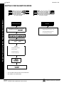
ACTIVATE FAULT FIND (Available with the Dealer Program Code)
This troubleshooting aid will help the installer locate swingers. When accessed, two things occur:
The loop response of each zone is set for the fastest response time.
Causing or repairing a fault activates the sounder for about 7 seconds.
Tapping and poking at suspect points, the installer can easily locate swingers by listening for the beep. This eliminates
the need of returning to the keypad to visually check after each attempt. Press the C button to restore normal
operation. Arming the system automatically cancels the Fault Find Mode. Note: When testing wireless systems, the
keypad will not beep if the signal strength is less than "3".
The "Fault Find" function (a Function Menu selection) is enabled, and normally causes all zones to give a two second
beep at the keypad(s) when any zone is faulted or restored. As required by SIA CP-01, Fault Find is expanded with
the following features when Digital Dialer Report Enter/Exit Test Mode is programmed. This option is programmed
when "Enable CP-01 Feature" is selected in the Easy Program Menu:
• When Fault Find is entered, it reports to Central Station that "Test Mode" is in progress.
• Fault Find can not be initiated from an armed panel, and all digital dialer reporting is inhibited while in Fault
Find.
• Fault Find Central Station Reporting Code is located at address 2053.
• Keypad will display the following warning that the system is in Fault Find: "FAULT FIND RF SIG POWER - - "
• If 24-hour zone is open at end of test, no report is sent. If a 24-hour zone is tripped and not restored during
• When Fault Find is exited by pressing C, a Fault Find Restore Report will be sent.
ACTIVATE PROGRAM
At the Keypad, press the NEXT/YES button to activate the User Program (Program-1) Mode or Dealer Program
(Program-2) Mode, depending upon the code entered. Scroll through the program functions using the NEXT/YES
button and the PRIOR/NO button.
ACTIVATE DOWNLOAD
Used on-site for remote downloading of a control-panel program from the PCD-Windows Quickloader Download software. Press the NEXT/YES button to initiate the data transfer.
ENABLE DEALER MODE
Refer to the chart on page 52.
ENABLE USER MODE
Refer to the chart on page 54.
L
NAPCO Security Systems
X
GEM-P1664 Installation Instructions
Basic Operation
Fault Find, when the mode is exited the zone will display as "Faulted" on the keypad display.
Page 26
WI1424A 1/06
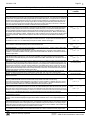
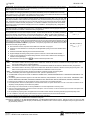
KEYPAD MESSAGES
The GEM-RP1CAe2/GEM-K1CA Keypads can display the below messages. The GEM-RP2ASe2/GEM-K2AS will display similar
abbreviated messages that may scroll through two screens. Note: See page 7 for a listing of the keypad specific User Guides available. These User Guides contain more details regarding the various keypad messages.
SYSTEM READY - All zones operating; system can be armed. 1
through 4 = Area.
SYSTEM TROUBLE/E06-NN SERVICE.
trouble. NN = receiver number.
Rf transmitter low
Rf receiver response
ARMING YYY/XXX SECONDS - Exit delay in progress. XXX = exit
time remaining in 10-second decrements; YYY = AWAY or
STAY. Arming then becomes ARMED.
SYSTEM TROUBLE/E07-00 SERVICE. Download failure.
DISARM NOW/XXX SECONDS - Entry delay in progress. XXX =
entry time remaining in 10-second decrements.
SYSTEM TROUBLE/E09-00 SERVICE, NO PANEL PROGRAM.
System cold start not programmed after address 2286.
SYSTEM ARMED - Panel armed.
keypads only.
GEM-RP1CAe2/GEM-K1CA
CAN'T ARM SYSTEM/ZONE FAULTED - Arming attempted with
Priority Zone in trouble. Secure zone to arm.
DAY ZONE TROUBLE - Trouble condition on Day Zone, followed
by one or more zone descriptions.
INVALID ENTRY/TRY AGAIN - Wrong code/time/area number
entered.
CAN'T ARM SYSTEM/PRESS RESET KEY - Arming attempted
with System Trouble present. Press the C button and then
arm the system.
ALARM - Alarm condition, followed by one or more zone
descriptions.
FIRE ALARM - Alarm condition on a Fire Zone. Enter your code
then press the
U or D button to silence the sounder.
Correct
the cause of the alarm, then press the C button again. Fire
alarm condition, followed by one or more zone descriptions.
SYSTEM TROUBLE - A System Trouble display will be followed by
one or more of the following error codes:
AC POWER FAIL/E01-00 SERVICE. Power failure. Check
power transformer. Check for blown fuse or circuit breaker;
general power outage.
LOW BATTERY/E02-00 SERVICE. Battery below 11 volts. If
not recharged within 24 hours, replace it.
COMM FAIL/E03-00 SERVICE. Unsuccessful communication
to central station. Note: Will also display if panel improperly
programmed to report; i.e., Report Alarm, Report Codes,
Subscriber ID Numbers, etc. must be programmed.
WIRELESS TROUBLE/04-NN SERVICE. Wireless transmitter
supervisory failure. NN = transmitter number.
X
GEM-P1664 Installation Instructions
SYSTEM TROUBLE/E08-00 SERVICE. Telephone line failure
(system trouble displays after a fixed 60 second delay).
SYSTEM TROUBLE/E10-NN SERVICE.
failure. NN = keypad number.
Keypad response
SYSTEM TROUBLE/E11-NN SERVICE. Keypad tamper cover
removed. NN = keypad number.
ZONE FAULTED - One or more zones not secured. Display status
for zone description(s). GEM-RP1CAe2/GEM-K1CA only.
Keypad Messages
WIRELESS LOWBATT/E05-NN SERVICE.
battery. NN = transmitter number.
SYSTEM TROUBLE/E12-NN SERVICE.
module failure. NN = module number.
Expansion zone
SYSTEM TROUBLE/E13-NN SERVICE.
removed. NN = module number.
EZM module cover
SYSTEM TROUBLE/E14-NN SERVICE. Relay board response
failure. NN = relay board number.
SYSTEM TROUBLE/E15-NN SERVICE. Wireless transmitter
tamper cover removed. NN = transmitter number.
SYSTEM TROUBLE/E16-NN SERVICE. Receiver jammed. NN
= receiver number.
SYSTEM TROUBLE/E17-NN SERVICE.
removed. NN = receiver number.
Receiver cover
SYSTEM TROUBLE/E18-NN SERVICE. Key fob RF transmitter
low battery. NN = key fob transmitter number.
SYSTEM TROUBLE/E19-00 SERVICE.
Internal user memory
error. Select RESET SYSTEM TBL. Press the
U
or
D
button, then the C button.
SYSTEM TROUBLE/E20-00 SERVICE. Internal dealer memory
error.
SYSTEM TROUBLE/E22-NN SERVICE. No trip detected on PIR
Supervision Zone within programmed Sensor-Watch time.
NN = Zone number. To reset, press NEXT/YES button at
“RESET SENSOR MSG” function display.
SYSTEM TROUBLE/E27-00 SERVICE.
installing company for service.
Printer Failure. Call
SYSTEM TROUBLE/E39-00 SERVICE. Receiver capacity error.
SYSTEM TROUBLE/E40-00 SERVICE. RF Self-Test failure.
SYSTEM TROUBLE/E41-NN SERVICE. Trouble condition on a
Fire Zone. Press C button to silence the sounder.
Correct the trouble, then press the C button again.
SYSTEM TROUBLE/E51-00
Supervisory.
SERVICE
-
Alarm
Output
SYSTEM TROUBLE/E99-00 SERVICE. Keypad Panic shorted
too long (RP2/K2 and RP3/K3 keypads).
NN OUT OF SYSTEM - Keypad inoperative.
number.
NN = keypad
FAULT FIND/RF SIGNAL POWER - Fault-find Mode activated.
L
NAPCO Security Systems
WI1424A 1/06
Page 27
GLOSSARY
Note: Displayed messages shown are for the GEM-RP1CAe2 and/or GEM-K1CA keypads.
Other keypad messages are similar but abbreviated. Refer to the GEM-P1664 Programming
Manuals (WI1422 and WI1423) for specific address numbers.
Abort Delay (Do not program for UL Applications)
An Abort Delay is a delay period that allows cancellation of the central-station report by disarming the control panel before a report
is sent. If Enable CP-01 Limits is enabled, the Abort Delay is 30 seconds (which cannot be removed but can be adjusted to within
the CP-01 specification of 15-45 seconds). In addition, if an attempt is made to change the Abort Delay to less than 15 seconds or
more than 45 seconds, the time will be entered as 30 seconds. If enable CP-01 Limits is NOT enabled, the factory delay time will
be set at 30 seconds, and can be deleted or increased to 255 seconds. Refer to "Enable CP-01 Limits" in this glossary. Enable
program zones for Abort Delay and select an Abort Delay Time. Also, a Pre-Alarm Warning may be selected for zones allowing a
keypad indication of alarm with no alarm outputs or central station reporting for the duration of abort delay time.
AC Failure; AC-Fail Report Delay
If AC power is removed from the control panel, "AC POWER FAIL/E01-00 SERVICE" will display at the keypad with a flashing "SYS/TRBL"
icon as a reminder and a pulsing sounder. Press C to silence the sounder; the "SYS/TRBL" icon reminder will remain on and
"SYSTEM READY" will appear in the display. If a User Code is entered within 5 minutes, the panel may be armed. After 5 minutes, the
system trouble will again display.
AC Failure may be programmed to activate the Alarm Output, Pulsed Alarm Output, PGM1 Output, PGM2 Output, Relay Outputs
and/or report to a central station by selecting AC Fail Report Event Telco 1, AC Fail Report Restore Telco 1, AC Fail Report Event
Telco 3, AC Fail Report Restore Telco 3. The AC Trouble Fail Display, AC Fail Logging, and AC Fail Report to the central station
will occur immediately unless an AC Fail Report Delay is programmed.
Access Number for Outside Line (CS Receiver Telephone Number Access)
Some subscribers will have a telephone system that requires one digit to access an outside line. The first dial tone encountered
(prior to the access number) may have a frequency that is different from that of the accessed dial tone (440Hz). One or more 4second Pre-Dial Delay "D"s may be entered before any of the CS Receiver Telephone Numbers instead of a dial tone with
frequency "E". See Pre-Dial Delay; Telephone Numbers. (Note: The panel features automatic dial-tone detection and will normally
not require any "E"s. To disable this feature, see CS System Report Options in the Programming Instructions WI1422 and WI1423).
If the subscriber's system uses an access number, contact the telephone-equipment supplier to find out if a dial tone other than
440Hz is received prior to dialing the access number. If the communicator must delay before dialing the access number instead of
attempting to recognize the dial tone, find out how many 4-second delays must be programmed.
Alarm on Day Zone See Day Zone
Alarm Outputs (See Wiring Diagram for UL requirements); Alarm Output Duration
The GEM-P1664 has three outputs: Alarm (Burg. & Fire), PGM1 and PGM2. The following table summarizes wiring for signaling an
alarm in typical installations. See Time Selection for timeout durations.
L
NAPCO Security Systems
X
GEM-P1664 Installation Instructions
Glossary
Access Control; Access Control (Panel Access) on PGM2 Output; PGM2 Output Access Control Time; Panel Access
Note: The GEM-P1664 has not been evaluated by UL for compliance with UL294 (Access Control Systems).
The PGM2 Output can be programmed to activate for a programmable period of time (2 to 254 sec.). This allows it to be used for
access functions such as opening and closing a garage door, or remotely activating an electric door strike through an RB1000 relay.
This is achieved by programming a new KeyFob option, Access on PGM2 Output, into the Aux. 1 or Aux. 2 option locations on the
Wireless KeyFobs screen. This feature also requires a valid time to be entered into the PGM2 Output Access Control in the Time
Selection Screen.
If Access Control on PGM2 Output is selected, entering the Access Code (see User Code Programming in Easy Menu Driven Mode
Programming) while disarmed will trip the panel's PGM2 Output. (This is commonly used to activate a door strike for the purposes
of remotely unlocking a door). Each keypad is individually selected for Panel Access. Also program PGM2 Output Access Control
Timeout. Note: Do not program the PGM2 Output as an output on alarm. Do not program Keyfob Chirp on PGM2, unless Enable
Bell Output on RF Arming is selected also.
Panel Access is selectable for any keypad 1–7 by selecting the appropriate Area Option of any User Code (see User Code
Programming in Easy Menu Driven Mode Programming); select the Panel Access option for those keypad numbers (1–7) that are to
respond to the User Code. However, if the Access Option is programmed, the code will no longer function as an Arm/Disarm Code.
Entering a valid code at the keypad will cause the PGM2 output on panel to turn on for the programmed time. The RB1000 Relay
may be used to activate a door strike, and power to the door strike should be supplied from an independent power source.
Page 28
WI1424A 1/06
OUTPUT
WIRING
REMARKS
Alarm Output (Burg.)
3(+) & 4(–)
Single Bell Output; program Alarm Output for Burg. See System Options in the Programming Instructions WI1422 and WI1423.
Pulse Alarm Output
(Pulsed)
PGM1 Output
3(+) & 4(–)
Single Bell Output; program Pulsed Output for Fire. See System Options in the Programming Instructions WI1422 and WI1423.
5(+) & 7(-)
PGM2 Output
5(+) & 8(-)
Programmable Output. See System Options in the Programming Instructions WI1422 and WI1423.
Programmable Output. See System Options in the Programming Instructions WI1422 and WI1423.
Alarm Outputs
In UL installations, (1) see Time Selection for timeout requirements; (2) Fire zones must be programmed for PulseAlarm Output, and
the option "Change Pulse Alarm to Cadenced Alarm" must be programmed. Note: For PGM1 and PGM2 are Lug Active-Low
Outputs.
Alarm; Alarm Restore Telco 1/Telco 3 See Report Telco 1/Telco 3
Alarm; Alarm Restore Telco 2 See Backup Report on Telco 2
Alarm Supervisory
An Alarm Supervisory indicates that there is an open in the circuit to the Alarm (Bell) Output and requires immediate attention. A
2.2K EOL resistor is required. See wiring diagram.
Glossary
Ambush (Keypad Ambush); Ambush Codes; Enable Global Ambush
There are two types of Ambush Codes: (1) A 2-digit code (prefix) that is entered immediately prior to (and as part of) the regular User
Code and (2) A separate and unique User Code. Disarming with an Ambush Code will cause a silent report to be sent to a central
station. Thus, should a user be forced to disarm, he can silently signal an emergency while appearing to be merely disarming the
system. The Ambush Zone will automatically report when programmed to report an alarm.
Ambush Type 1: (a 2-digit prefix code), this type must not be used in a SIA CP-01 compliant system. Enable as follows: (a) select
"Ambush to Report Event Telco 1/Telco 3"; (b) select "Enable Global Ambush Code"; enter "Global Ambush Code"; and (c) enter an
"Ambush CS Report Code". Each keypad is enabled for "Ambush" individually.
Ambush Type 2: (a separate and unique user code), this type must be used in a SIA CP-01 compliant system. Enable as follows: In
the Easy Menu Driven Program Mode, the menu selection "Enter User Code" is used to program a user code with a "blank(•) 5" in
the area for which the Ambush Code will be used. Enable all other locations and program as follows: (a) select "Ambush to Report
Event Telco 1/Telco 3"; (b) enter an "Ambush CS Report Code". Each keypad is enabled for "Ambush" individually.
Be sure to inform the user what their Ambush Code is, and that the Arm/Disarm Code must be entered less than 10 seconds after the
Ambush Code for an ambush report to be sent. When "ENABLE GLOBAL AMBUSH" is selected and no Ambush code has been
entered and the keypads have been selected for AMBUSH, then the AMBUSH CODE will default to "99".
Answering Machine Pickup Without Line Seizure See Callback-Method Download.
Anti-Jam Communicator Time
If the communicator does not detect a dial tone within 12 seconds, the Anti-Jam feature will be activated. That is, the communicator
will go off line for a 16-second anti-jam interval in order to free the telephone circuit from an incoming call, then make another 12second attempt at dial-tone detection. If still unsuccessful, the communicator will again go off line for 16 seconds, then proceed to
dial anyway.
Areas; Zone Area 1–Zone Area 4; Priority Area Arming
Although the default program will automatically set up Zones 1 through 8 for Zone Area 1, the panel may be partitioned into two
areas. Every zone must be assigned to at least one area to be used. At least one zone must be assigned to Area 1. If a zone is
selected for both areas, that common zone will not arm until both areas are armed. If any area disarms, the common zone will
disarm.
Keypad Area Assignments
Silencing Alarm Area (determines which alarms an area may silence);
Subscriber Opening/Closing ID Numbers and Event ID Numbers (if reporting);
System Trouble Subscriber ID Number
If "Priority Area Arming" is selected, the Priority Area must be armed before the Arming Area can be armed.
Auto-Arm if not closed at end of Window; Closing Window; Fail to Close (Not for UL Installations)
AUTO-ARM can be programmed to arm at a specific closing Time (such as: 17:00 representing 5:00 pm), for a notification length of
time (such as: 00:02 representing 2 minutes), and a FAIL-TO-CLOSE has been enabled for a specific day of the week and area, and
X
GEM-P1664 Installation Instructions
L
NAPCO Security Systems
WI1424A 1/06
Page 29
Auto Arm if not closed at end of window. When the start time is reached, the display will notify the occupants that an Auto-Arm will be
initiated in the notification period length of time. After that period has expired, a 15 minute period will count down to Auto-Arm with
the sounder pulsing. Auto-Arming may be canceled by arming and disarming the panel. An auto-Arm will be reported as User 33.
Auto Arming can be delayed from 1 to 4 hours by pressing the A or R button during the 15 minute Auto Arm Period until "TO
DELAY AUTO ARM" is displayed and press the number of hours to delay followed by the U or D button.
Auto Output Test on Arming
If selected, this will activate the Burglary Output briefly 10 seconds after the area is armed. If the alarm does not sound, the device
may be defective.
Auto-Bypass (Do not program for UL installations); Auto-Bypass Re-entry
Zones programmed for "Auto-Bypass" will be bypassed (automatically removed) if in trouble when arming. A momentary beep will
sound at the keypad to warn that the system has been armed without the protection of the auto-bypassed zone. (Note that the exit/
entry door should not be used for Auto-Bypass, otherwise the Exit/Entry Zone will be auto-bypassed). Note: A zone in trouble that is
not programmed for "Auto-Bypass" will cause an alarm on arming after a 10-second arming delay.
If "Auto-Bypass Re-entry" is selected, securing a zone that is programmed for Auto-Bypass, while armed, will cause that zone to reenter the system in an armed state.
Auto Interior Bypass/Easy Exit (STAY MODE) See Interior Stay Zones
Auto-Reset; Auto-Reset After Burglary Output Timeout (Do not program for UL installations)
If a zone detects an alarm condition and is selected for "Auto-Reset", it will automatically rearm itself as soon as the alarm condition
is cleared. Auto-Reset may be delayed to occur after the Alarm Output timeout period by selecting "Auto-Reset After Burglary Output
Timeout" and "Auto-Reset" . Zones that are not programmed for "Auto-Reset" will not be capable of signaling another alarm until (a)
the cause of the alarm has been corrected and (b) the control panel is disarmed. Also see Swinger Shutdown.
Backup Report on Telco 1/Telco 2
If "Backup Reporting on Telco 1/Telco 2" is selected and the communicator does not reach the first telephone number (Telco 1) after
three attempts, seven attempts will be made to reach the second telephone number (Telco 2). Enter Subscriber Identification
Numbers for Telephone 2 and other information required for Telephone 2. Also program Backup Report on Telco 2. Any zone
programmed to report to Telco 1 will backup report to Telco 2. Note: Subscriber Identification Numbers for both Telephones 1 and 2
must be entered, even if they are the same. Any restore will also first transmit to Telco 1 then Telco 2. The alarm and restore may
not be transmitted to the same telco telephone number.
Battery
12Vdc standby power source in the control panel is used to provide backup protection in the event of a power loss. The battery is an
integral part of the system and must be installed, even if ac power is present. Change the battery every 5 years or as required.
Burglary Output See Alarm Outputs
Call Waiting See Disable Call Waiting
Callback-Method Download; Disable Second Call Answering Machine Override (MUST program for UL installations); Disable
Callback Download (MUST program for UL installations); Callback Telephone Numbers; Disable Keypad Function-Mode
Download; Answer on Ring Number
Data may be downloaded remotely to the panel after a programmed number of rings (3 to 15) and a control-panel confirmation
callback. Program the "Number of Rings"; if not programmed, the panel will pick up after 15 rings.
The feature "2nd Call Answering Machine Override" allows downloading after (1) the panel detects 1 or 2 rings; (2) the panel does
not detect another ring for 8 seconds; (3) the panel detects another ring within the next 22 seconds. At this point, the panel will connect and allow the panel to communicate with the downloading computer. In this way, the panel overrides the answering machine.
The answering machine will pick up on its programmed number of rings, as usual. Note: The number of rings programmed into the
panel must exceed that of the answering machine.
Program "Disable Callback Download" to prevent unauthorized downloading to an unattended panel. Program "Disable Answering
Machine Download" to inhibit downloading to a telephone connected to an answering machine. Program "Disable Function-Mode
Download" to prevent downloading at the keypad.
Cancel; Cancel Code; Cancel Report to Telco 3; Cancel Window Duration (Report Cancel Window)
CANCEL is the preventing of a report from being sent by entering a user disarm code. If the area is disarmed during Entry Delay or
L
NAPCO Security Systems
X
GEM-P1664 Installation Instructions
Glossary
Auto Status Disable
For high security Installations, the automatic scrolling of Zone Faults can be disabled. When any zone is faulted, the display will read,
"Zone Faulted".
Page 30
WI1424A 1/06
the "Pre-Alarm Warning", then no report will be sent and no messages will be displayed at the keypad. If the area is disarmed during
the Abort-Delay, then an "Alarm Canceled' will be displayed at the keypad and no report will be sent. If the area is disarmed during or
within the Cancel Window Duration, then an "Attempting to Cancel" will be followed by an "Alarm Canceled" for a successful
cancellation. Otherwise, the report had been sent and will be responded appropriately to by the Central Station. Cancel must be
provided with a Central Station Telephone Number, proper Subscriber O/C Report ID Numbers and a valid Cancel Code to Telco 3.
A Cancel Window ("Report Cancel Window") is the duration that the system will attempt to cancel a report, after the report is sent.
Cancel Next Test Timer Report on Any Report See Test Timer
Central Station Receiver Data Format See Data Format
Chime (Displays "MONITOR" on GEM-RP2ASe2 Keypads); Chime Duration
This annunciator feature may be used on any zone to sound a tone at the keypad while disarmed when the zone goes into trouble.
Access the ACTIVATE CHIME function to enable or disable the Chime Mode. This feature is programmable by zone and "Chime
Timeout Duration". A time must be programmed for the chime to function. Note: "0" means no chime value is programmed.
Chime Zone 2
CHIME2 adds an additional tone onto the regular "Chime Zone" tone. It allows some zones to have distinctive annunciator chimes to
identify the door or zone. "Chime Zone" must be selected on any keypad for all area keypads to chime. While the standard chime
zone sounds a steady tone when a chime zone is faulted, Chime 2 will sound a pulsating tone when a Chime 2 zone is faulted. This
can be used to help the customer easily identify the door which has been opened. Program the zone as Chime 2 in the Zone
Features screen. This feature is programmable by zone and "Chime Timeout Duration".
Chirp Output on Keyfob Arm/Disarm
If enabled, when arming with a keyfob, the PGM2 output chirps.
Glossary
Clear Program
Caution: Erases the dealer program. Use this feature to start a new customized default program. Access Address Location, then
press the U or D button.
Closing Report; Closing Report Only on Conditional Closing; Conditional Closing; Include Selective/Group Bypass In
Conditional Closing/Status; Status Report; Disable Closing Report
On arming, the communicator can transmit a unique Closing Code for each user and a status report that identifies the problem zone
to the central station. Note that Subscriber Identification Numbers and a Closing Code and/or conditional closing code must be
entered for any closing report.
Select which users will report closings for each telephone number, even if "Closing Report Only on Conditional Closing" is selected.
Normally, a closing report will consist of the Closing Code and the number of the user that armed. If the user armed with an autobypassed zone (or selective/group bypassed zone if "Include Selective/Group Bypass In Conditional Closing/Status" was
programmed), the Conditional Closing Code will also be sent.
Select "Closing Report Only on Conditional Closing" to report only when arming with an auto-bypassed zone (and selective-bypassed
zone if "Include Selective in Conditional Closing/Status" is programmed).
Select "Status Report" to send a closing followed by a status report that identifies the problem zone(s). A typical Status Report is
represented by the following example.
Example (4/2 Format). A burglar breaks into a commercial establishment during the night, breaking the window foil on Zone 5. The
Open/Close Subscriber Identification Number is "1234"; the Alarm Code for Zone 5 is "3,5" (Burglary Zone 5); the Subscriber
Identification Number is "6789"; the Closing Code is "C". The communicator will send the following report to the central station.
When alarm occurs:
"6789 35" – Alarm, Zone 5
Closing Report:
"1234 C1" – Closing, User 1 (User 1 returned, inspected damage & rearmed; the same transmission would occur for
User 11, 21, 31, etc.)
"1234 F5" – Trouble, Zone 5 (zone status at time of closing: Window foil still broken; Zone 5 auto-bypasses, repair
required; the same transmission would occur for Zone 15, 25, 35, etc.).
Cold Start
Caution: Erases the entire program (codes, schedules, etc.), and loads the following defaults: 8 hardwire zones (Zones 1-8) are programmed in Area 1, with no other zone features enabled and no alarms generated. In addition, a Default User 1 Code of "123" is enabled as an Arming Code in Area 1, and after powering up, the installer is required to enter Program Mode using the Dealer Program
Default Code of "456789". Press C to exit the EZ Program menu. Access Location Cold Start, then press the U or D button.
Data Format
X
GEM-P1664 Installation Instructions
L
NAPCO Security Systems
WI1424A 1/06
Page 31
Ask the central station which of these formats to use.
Two-Digit or 4/2 Format. Some central-station receivers require that a four-digit Account Code followed by a two-digit Alarm Code be
sent in each report. Example. In a certain installation, the Alarm Subscriber Number is "1234"; a burglary alarm occurs on Zone 1.
The Alarm Code for Zone 1 is "3". The communicator will send "1234 31" (Account No. 1234; Alarm, Zone 1). 1400Hz Handshake/
Kissoff. 1400Hz Handshake overrides 2300Hz Handshake if both are selected. 2300Hz Handshake/Kissoff. Used with the following
receiver formats: Radionics, DCI & Franklin Slow; Radionics Fast.
Zone Number on Pulse Alarm.
If selected, an Alarm Code need not be programmed (the zone number will replace the Alarm Code),
however codes for restore, trouble, etc. are still required. Thus, in the foregoing example, if "E" is the designated Restore Code, and Zone 24
trips and is restored, the communicator will send "1234 24" (Account No. 1234; Alarm, Zone 24) followed by "1234 E4" (Account No. 1234;
Zone 24 Restored).
Single-Digit (Pulse Only) Format. The single digit sent for a particular digit of the zone number.
Sum-Check Format.
Sum Check is a sophisticated data format used to enhance the speed and check the accuracy of the received
transmission. This format should be preferred whenever the central station is capable of receiving it. After transmitting the Subscriber
Identification Number and the Alarm Code, the communicator sends a verifying digit that is the sum of both. The receiver compares the
verifying digit with the sum of the other numbers to check transmission accuracy. This feature eleiminates the need to repeat data and saves
time.
3/1 with Extended Restores. Some receivers require a three-digit Account Code followed by a single-digit Alarm Code. Example. In
another installation, the Alarm Subscriber Number is "123"; an alarm on Zone 1 is restored. The Restore Code for Zone 1 is "E,1". The
communicator will send "123 E" (Account No. 123 Restored); followed by "EEE 1" (Restored, Zone 1).
Modem Formats. Modem formats (SIA, Point ID) are preset and automatic but require a Type for each zone. Program Zone Type as follows:
Fire* = "1"; Panic = "2"; Burglary = "3"; Holdup = "4"; Gas Alarm = "7"; Heat Alarm = "8"; Auxiliary Alarm = "A" (Keypad displays "0"); 24-Hour
Aux. Alarm = "B".
Pager Formats. The control panel has provisions for dialing a pager phone number. The panel will wait for ringing, wait for silence, then
send its data. Caution: Because there is no handshake/kissoff, this feature should only be used for Double Reporting; it may not be used for
Backup Reporting. Only one report is sent for any call. Pager digits are limited to "0" through "9". Digits represented by "A" through "F" will
be converted to "0"s for transmission purposes. Pager formats are 10 digits, arranged as illustrated by the following examples.
FBI CP220.
Formats: Ademco Slow; Silent Knight Slow; Silent Knight Fast; DCI; Franklin Slow; SIA; Radionics Slow; Radionics Fast;
Universal High Speed.
Ademco 685. Formats: Ademco Slow; Silent Knight Slow; Silent Knight Fast; DCI; Franklin Slow; Radionics Slow; Radionics Fast; Universal
High Speed; Ademco Point ID.
Radionics 6500. Formats: Ademco Slow; Silent Knight Slow; Silent Knight Fast; DCI; Franklin Slow; Radionics Slow; Radionics Fast;
Universal High Speed.
Osborne-Hoffman Quickalert. Formats: Ademco Slow; Silent Knight Slow; Silent Knight Fast; DCI; Franklin Slow; SIA; Radionics Slow;
Universal High Speed; Ademco Point ID.
Silent Knight 9000. Formats: Ademco Slow; Silent Knight Slow; Silent Knight Fast; DCI; Franklin Slow; Radionics Slow; Radionics Fast;
Universal High Speed; SIA.
Date/Time
A Date/Time can be set in the Keypad Dealer Program Mode or Quickloader program. "Enable Keypad Set Date/Time Message" will
automatically request the date and time at the keypad after extended power failures (if enabled).
Day Zone (Open; Short); Alarm on Day Zone; Disable Auto-Reset on Day Zone; Reset Day Zone with Arm/Disarm Only; Day
Zone Trouble on Open
A Day Zone will give an audible and visual indication at the keypad if there is a problem on the loop while disarmed. Open- and shortcircuit conditions are programmed separately, by zone. This feature may be used to warn of a problem (a break in a window foil, for
example) during the day, when the panel is not normally armed. When the Day Zone is tripped, "DAY ZONE TRBL" and the zone
number(s) will alternately display at the keypad and the sounder will pulse. Press the C button to silence the sounder and reset
the keypad. "ZONE FAULT" will be displayed until the condition is corrected. If Reset Day Zone With Arm/Disarm Only is programmed, reset the Day-Zone indication at the keypad. A User Code is required to reset the keypad display. If Alarm on Day Zone
is programmed for a zone, a Day Zone condition will cause the alarm outputs programmed for that zone (sirens, relays) to activate. If
Day Zone Trouble on Open is programmed, a zone configured as a 24 hour zone reports an alarm on short and a Day Zone trouble
L
NAPCO Security Systems
X
GEM-P1664 Installation Instructions
Glossary
Alarms, restores, etc. are transmitted in a 3-2-4 arrangement representing Report Code, Descriptor and Account Number.
Example 1. Burglary, Zone 22 (Report Code = "3").
Transmits: 003 22 1234, where
003 = Report Code (always two zeros + programmable Report-Code digit, 0–9);
22 = Descriptor (2-digit descriptor, zone number: 01–64);
1234 = Account Number (4 digits, programmable).
Openings, closings, etc. are transmitted in a similar arrangement
Example 2. Closing, User 12 (Closing Code = "8")
Transmits 008 12 1234, where
008 = Report Code (always two zeros + programmable Opening/Closing digit, 0–9)
12 = Descriptor (2-digit descriptor (user number: 01–32);
1234 = Account Number (4 digits, programmable).
Keypad Report Codes and System Report Codes are transmitted in the same format.
Compatible Receivers. The following receivers are compatible with the GEM-P1664:
Page 32
WI1424A 1/06
on an open loop.
Note: (1) If a zone is programmed for both "Day Zone Open" and "Day Zone Short", either condition must be reset before the other
can activate. (2) Day Zone Short will not function if No EOL Resistor is also programmed. Report Trouble or Trouble Restore is programmed in conjunction with Day Zone Open/Day Zone Short and Trouble on Open/Trouble on Short (the trouble reported will be
that programmed under Day Zone Open and/or Day Zone Short).
Note: Do not program a Day Zone for 24-hour protection. The keypad will annunciate as a Day Zone but the panel will transmit an
Alarm Code and a Trouble Code when tripped.
Dealer Security Code
The factory-programmed Dealer Security Code is "456789". Use this code to enter the Easy Menu Driven Mode (Dealer Program
Mode) to program (or change) the Dealer Security Code. The Dealer Security Code is needed to enter the Dealer Program Mode,
thus allowing the dealer to program codes, zone features, reporting features and zone descriptions. This code should be changed as
required.
Dial-Tone Detection; Disable Auto Dial-Tone Detection
The panel features automatic dial-tone detection to ensure that a dial tone is present before the communicator dials. To disable this
feature, program an "8" in Location 0394.
When an "E" is programmed before the first digit of an outside telephone number, the communicator dial-tone detection circuit is set
to detect the standard 440Hz dial tone. The "E" is generally entered in the location immediately preceding the telephone number.
It may be necessary to program at least one 4-second pre-dial delay before a dial-tone detection "E". With certain nonstandard
exchanges, pre-dial delay "D"s may be used without a dial-tone detection "E". (See Access Number for Outside Line; Pre-Dial Delay;
Telephone Numbers)
Glossary
Digital Dialer Report Enter/Exit Test Mode
Initiation Report. At the initiation of a test, the control panel sends a message to the central station that a test is in progress. The
"Fault Find" function (a Function Menu selection) is enabled, and normally causes all zones to give a two second beep at the keypad
(s) when any zone is faulted or restored. As required by SIA CP-01, Fault Find is expanded with the following features when Digital
Dialer Report Enter/Exit Test Mode is programmed. This option is programmed when "Enable CP-01 Feature" is selected in the
Easy Program Menu:
•
When Fault Find is entered, it reports to Central Station that "Test Mode" is in progress. On completion of the report, a RingBack will be given.
•
•
•
Fault Find can not be initiated from an armed panel, and all digital dialer reporting is inhibited while in Fault Find.
•
When Fault Find is exited by pressing C, a Fault Find Restore Report will be sent, and upon completion of the report a
Ring-Back will be given.
Keypad will display the following warning that the system is in Fault Find: "FAULT FIND RF SIG POWER - - "
If 24-hour zone is open at end of test, no report is sent (GEM-P1664). If a 24-hour zone is tripped and not restored during
Fault Find, when the mode is exited the zone will display as "Faulted" on the keypad display.
Disable Call Waiting (Touch-tone® Dialing Only)
A digital communicator connected to a telephone line with Call Waiting may be disrupted by this feature. However, most lines with
Call Waiting also have Selective Call Waiting, which permits the feature to be turned off by dialing a "*70" just before the telephone
number. A "*" will be dialed by programming a "B".
If the installation has the Call Waiting feature, be sure that it also has Selective Call Waiting, and confirm the disable code with the
telephone company. Then program this code ("B70") directly before the phone numbers (after dial-tone detection or pre-dial delay) in
the telephone-number locations. See Telephone Numbers.
Caution: Should the user cancel his Call Waiting service, the communicator will dial a wrong number unless the phone number is
corrected.
Disable Call Waiting on 1st Attempt
Cancel "*70" after the 1st dial attempt. Default is disabled. When enabled, this option will dial the Central Station telephone number
as it is programmed in the panel. If the first communication is unsuccessful, the next and remaining dial attempts will remove the *
star button (entered as a "B" from the keypad) and the 2 subsequent digits from the Central Station telephone number.
Disable Callback Download See Callback-Method Download
Disable Code Required for Easy Bypass (Do not program for UL installations)
Any or all zones (1-64) programmed for Selective Bypass may be removed from the system, but each must be removed separately.
Refer to BYPASSING ZONES in Section 3 for operation. Security Bypass, recommended for commercial applications, requires entry
of a valid user code. Easy Bypass, recommended for residential applications, is selected by programming Disable Code Entry for
Easy Bypass; this will permit bypassing/unbypassing zones without the need of entering a code. Do not program this feature in high-
X
GEM-P1664 Installation Instructions
L
NAPCO Security Systems
WI1424A 1/06
Page 33
security applications. When one or more zones is bypassed, the BYPASSED reminder on the GEM-RP1CAe2 keypad will display.
Disable Code Required for Easy Bypass is enabled by default.
Disable Function-Mode Download See Callback-Method Download
Disable Openings/Closings
Provides the flexibility of disabling openings and/or closings for any area(s).
Disable Handshake on Xmit (All Formats)
Causes data transmission to wait one second after dialing a pager telephone number before sending data.
Disable PGM2 Clear on Disarm
PGM2 will not clear when a user code is entered to disarm.
Disable System Trouble Audible Timeout
If the trouble occurs when disarmed, the sounder will now automatically time out in 10 minutes, without the need to press [RESET].
(MUST be programmed in UL installations)
Disable Wait-for-Silence (Pager Format)
Causes data transmission to start immediately after the pager telephone number.
Disable Zone Fault Scrolling/Disable Auto Status
Non 24-Hour Zones that are open (or shorted) normally display "ZONE FAULTS" (while disarmed) followed by the zone number(s) and
description(s). In high-security applications, program Disable Auto Status. Unsecured zones will then be indicated by a "ZONE
FAULTED" display without zone numbers displayed. Status may be displayed manually using the DISPLAY STATUS function.
Double Reporting See Report Telco 3
Easy Exit (Not evaluated by UL)
While armed in the Interior Mode, Easy Exit can be initiated by pressing D or U. Easy Exit restarts the Exit delay, allowing a User
to exit an armed premises without disarming and rearming the system. Disable D or U buttons as Easy Exit.
Easy Programming of Auto download ID #'s and PC Preset Callback # (GEM-RP1CAe2/GEM-K1CA only)
It is now possible to set the PC Preset Auto download ID # and PC Preset Callback phone number from the GEM-RP1CAe2/GEMK1CA Easy Program Mode.
1. Enter Easy Program Mode and press PRIOR/NO until Central Phone # is displayed.
2. Program an "F" followed by the Auto Download ID # (2 digits) and then the Callback Telco # (up to 13 digits).
3. Press U to save.
4. Exit Program Mode ([RESET] [RESET]).
5. Enter Function Mode
6. Go to Function "ACTIVATE DOWNLOAD Y/N" and press NEXT/YES.
7. The panel will automatically call the PCPreset computer and download the program on the specified Auto DL line #.
Note: After the auto download of the control panel program, the system must be fully tested.
--See following example:
L
NAPCO Security Systems
X
GEM-P1664 Installation Instructions
Glossary
"E" Lugs (E5, E15, E19) (Do not program for UL installations)
E5 - Lug E5 is used for Line Seizure. It is normally at 12V and when the telephone line is seized it goes to approximately 1V DC.
E15 - Lug E15 is used for Armed Status, either Armed Stay or Armed Away. When the system is armed it goes to approximately 1V
DC. For multiple area systems: If only 1 area, Lug E15 goes active low when area 1 is armed; if 4 areas, areas 1 through area 4
have to be armed for Lug E15 to go active low.
•
Lug E15 Area 1 Armed Away Only: When enabled, Lug E15 will activate when area 1 is armed Away. Note: If this
feature is not selected, the E15 Lug will, by default, activate when the system is armed (all areas).
E19 - Lug E19 is the Listen in Lug. It is an input and when it is forced low the panel will silence the keypad sounder and bell outputs
so that the Veri-phone can listen to activity at the residence. See Veri-Phone (WI783): Silence All Outputs During Audio
Session. Use Napco Part No. WL1 for field wiring.
Page 34
WI1424A 1/06
Enable Alarm Output on Telco Fail only when Area(s) Armed (Alarm Output Only when Armed)
Example: Program an Auto Download ID # of 07 and a PC Preset Callback # of 1-516-842-9400
• Go to Central Phone # input screen and press:
[*] [5]
‘F’
[0] [7]
[1] [5] [1] [6] [8] [4] [2] [9] [4] [0] [0]
Auto DL ID#
Callback Phone #
[ON/OFF]
Save
Allow Telephone Line Fault test to produce an Alarm Output only when armed. Note: requires "System Features: Alarm Output",
"Telco Fail" and version 9 or later panel.
Enable CP-01 Egress Tones Only: Enable this feature if you want exit and entry sounds only--without setting any other CP-01 features. When enabled, the Exit Delay keypad sounder (including the Exit Urgency sound during the final 10 seconds of the Exit Delay)
is enabled.
Enable CP-01 Limits
When enabled, three time limits are enabled as per the SIA CP-01 standards: (1) Exit Delay Time: If an attempt is made to change
the Exit Delay time to less than 45 seconds the time will be entered as 60 seconds. The maximum programmable time is 255 seconds; (2) Entry Delay: If an attempt is made to change the Entry Delay time to less than 30 seconds the time will be entered as 30
seconds. The maximum programmable time is 255 seconds; and (3) Abort Delay: If an attempt is made to change the Abort Delay to
less than 15 seconds or more than 45 seconds the time will be entered as 30 seconds.
Note: In accordance with UL standards, the aggregate of the Entry Delay time and Abort Delay time "window" will not be programmed to exceed one minute. Note: When "Enable CP-01 Limits" is enabled, the Exit Delay keypad sounder (including the Exit
Urgency sound during the final 10 seconds of the Exit Delay) is enabled. Note: If "Enable CP-01 Limits" is enabled in EZ Programming, any Zone in a Group will only activate an alarm and send a report ONCE. After the Zone has reported, it will remain in the
Group and may still initiate the Zone ANDing sequence.
Glossary
Enable Keypad 1 Only Programming: In version 01 of the GEM-P1664 panel, programming is allowed from any keypad by default.
Program to restrict programming to Keypad #1 only, if needed.
Enable Local Alarm on First Zone "AND" Trip See Zone ANDing (Do not program in UL installations)
Enable TCP/IP Communications
Using the NetLink NL-MOD TCP/IP communications module accessory, the GEM-P1664 can report alarms via contact closures or via
its bell output but cannot report alarm data such as point ID information. The panel can, when the NL-MOD is visible on a network,
receive Windows Quickloader programming information or transmit panel log information over the network. Refer to the NL-Mod Installation Instructions WI1242 for more information.
Enable Telephone Line Fault Test
Enable Line Fault Test will cause the panel to monitor the phone line. A failure will display as "SYSTEM TROUBLE/E-08 SERVICE" for
Telco Line Fail. Program this system trouble to activate the Burglary Output.
Enable 2-Count Swinger Shutdown See Swinger Shutdown
Exit/Entry Delay; Exit/Entry 1; Exit/Entry 2; Entry Relay
Delays permit exit and entry through the Entry/Exit Zone(s) after the system is armed without setting off an immediate alarm. Entry
delay allows the user time to enter and disarm the panel. Exit delay allows the user to leave the premises after the panel has been
armed. Unless the keypad has been configured otherwise, the sounder will come on and will pulse during the last 10 seconds of
entry delay to remind the user to disarm.
Two individually-programmable entry-delay times are provided to accommodate different entry zones. If two or more Exit/Entry
Zones are entered in succession, the delay programmed for the last Exit/Entry Zone entered will take precedence over all others.
Exit-Delay time and Entry-Delay time may each be programmed for up to 255 seconds (4 minutes). See Time Selection.
An external relay may be programmed to trip upon entry (see Programming Manual: Relay Event ID Codes, Area Entry Relays), and
remain on for a programmed duration.
Note: In UL installations, maximum exit delay is 60 seconds; maximum entry delay is 45 seconds. In UL Mercantile installations,
maximum entry delay is 60 seconds.
Entry delay may be canceled by pressing the F button prior to arming, however it will be restored automatically upon disarming.
Exit/Entry Follower
A zone programmed as an Exit/Entry Follower will ignore detection during the exit delay, and only during entry delay if the Exit/Entry
Zone is entered first. Thus, detection devices (passive infrared detectors, for example) along the path between the keypad and the
exit/entry door will not signal an alarm during exit/entry delay under normal conditions. However, if a device in the Exit/Entry Follower
Zone detects a violation when the exit/entry door has not first been entered, there will be no entry delay and the Exit/Entry Follower
X
GEM-P1664 Installation Instructions
L
NAPCO Security Systems
WI1424A 1/06
Page 35
Zone will go into an instant alarm. If the panel is armed with the entry delays canceled (Instant protection), any violation on the Exit/
Entry Zone or the Exit/Entry Follower Zone will cause an immediate alarm.
Exit Time Restart
This option allows for the following scenario prior to the end of the Exit Time: a violation of an entry/exit zone, a restore, and a second violation of an entry/exit zone restarts the Exit Time. The panel does not allow the Exit Time to be restarted more than once.
The default setting for this option is enabled.
Expansion Module Zones; EZM Type; EZM Tamper See Tamper
Zones 9–64 or 17-64 (with "Zone Doubling" enabled) are expansion zones added to the basic system using expansion zone modules
(EZMs). Any combination of GEM-EZM8 (8 zones) and/or the 4-zone EZM modules integral to each GEM-RP1CAe2 keypad may be
used. Refer to the instructions accompanying each module for wiring information.
Each GEM-EZM4/8 Zone Expansion Module has series zone doubling and supervision capability. When an EZM is selected for zone
doubling, the EZM will respond as EZM 1 (zones 17 to 24) or EZM 3 (zones 25 to 32) when polled. (Refer to GEM-EZM4/8 Installation Instructions). The EZM zone doubling or loop supervision functionality can be set to either follow the panel configuration or to act
as a standard non-zone doubled EZM. Program (see Programming Instructions) to enable all EZM's to follow the attributes of the
control panel (global panel feature). Note: A GEM-EZM8 cannot be used if the panel is set for loop supervision or zone doubling
and this feature is enabled.
Regardless of how the modules are arranged, the expansion zones are divided into consecutively-numbered groups of four. Each 8zone module comprises two groups. Each group is assigned a number.
EZ Arming (Easy Arming); Easy Arming Closing Report
Permits quick arming by simply pressing the
D
button for "Classic" RP Style keypads.
Each keypad may be individually
programmed for Easy Arming (see Keypad Features). Disarming still requires entry of a valid user code. NOTE: Do not program in
UL installations. If closings are reported, Easy Arming will report as User 67. Press and hold P or Q to EZ Arm "K Series" keypads.
Fire; Keypad Fire
Any zone may be programmed for Fire. Connect normally-open devices across a Fire Zone. (The EOL2.2K end-of-line resistor must
be installed). A short across the zone will cause a fire alarm, which will be indicated at the keypad by a "FIRE ALARM" LCD display and
pulsing sounder. An open circuit on the Fire Zone will identify a trouble and cause flashing "SYSTEM TROUBLE/E41-00 SERVICE" LCD
display and pulsing sounder after a 10-second delay. The sounder may be silenced by pressing the C button. The LED will go
off within 30 seconds after reset if the alarm or trouble is cleared. For Smoke-Detector Reset, see Alarm Outputs. Fire or Keypad
Fire can be made to trip an alarm or report to Central Station. If Keypad Fire is programmed, pressing both the 7 and G
buttons at the same time will sound a fire panic alarm and display "FIRE ALARM" at the keypad. The Keypad Fire function is
supplementary to the hardwired zones. Note: This feature shall not be considered a substitute for listed manual initiating devices. A
fire condition that has not been restored will cause the zone number and description to scroll. To reset (acknowledge) the condition,
enter a valid code, then press the U button.
Fire Verification (Not for use in California)
An alarm on any Fire Zone programmed for "Fire Verification" and connected to the fire power terminal will cause all fire zones to be
powered down for 12 seconds. (All devices must be wired with + power on Terminal 25). After this time, power is restored and a 4second power-up time is started. Thereafter, the zone will be active again. This represents a total processing delay of 16 seconds
from the time the alarm is first detected. If an alarm condition still exists at this time or reoccurs within 2 minutes, an alarm will be
initiated, otherwise the zone will return to its original state. Note: A zone programmed for "Fire Verification" must be programmed as
a "Fire Zone" as well.
GEM-Print
A printer can be made to print all logged operations directly from the panel, when programmed for "Enable GEM-PRINT Module" and
a separate Gem-Print Module is added to the panel.
Include Selective Bypass In Conditional Closing/Status See Closing Report.
L
NAPCO Security Systems
X
GEM-P1664 Installation Instructions
Glossary
EZ Zone Doubling
The control panel zone configuration may be expanded from 8 to 16 zones without the use of EZM Modules. To do so simply select
"Zone Doubling" and connect zones as shown in Wiring Diagram. The 3.9K EOL resistor must be placed at the end of the loop of the
higher zone. For proper supervision, the 2.2K EOL resistor must be placed at the end of the loop of the lower zone.
Note: If Zone Doubling is to be used, then normally closed devices must be wired to both zones. If Normally open zones for fire or
panic devices are required, then the lower zone (2.2K EOL resistor) must be used and the higher zone (3.9K EOL resistor) must not
be programmed for any area.
Page 36
WI1424A 1/06
Inhibit System Trouble Audible at Keypad (Do not program in UL installations)
For installations where an audible during a system trouble is not desired, an option, Inhibit System Trouble Audible can be enabled.
Regardless of the system status (Armed or Disarmed) there is no keypad sounder in the event of a system trouble. However, the
trouble will still scroll in the keypad display until [RESET] is pressed and the SYS TBL icon will display until the trouble is restored.
• To disable System Trouble Audible, enable the option Disable System Trouble Audible in the QL-Windows Keypad Features
screen.
Interior Stay Zones; Interior Normally Bypassed (Stay Mode); Auto Interior Bypass (Stay)/Easy Exit
Removal of a programmed group of interior (Stay) zones from the system will permit freedom of movement throughout the premises
but still allow protection from intrusion through armed perimeter zones. Pressing E prior to arming will select the Interior Zones,
then arm to bypass. The next time the control panel is disarmed, all bypassed zones will automatically revert to non-bypassed
(disarmed) zones. When E is pressed, the "BYPASS" reminder will come on.
The bypassed zones may be displayed on the keypad (see GEM-RP1CAe2 FUNCTION MODE).
If Interior Normally Bypassed is selected, all Interior (Stay) zones will always be inactive. The "BYPASS" reminder will always display,
indicating that only partial protection will be provided upon arming. To temporarily restore interior protection, press E; the
"BYPASS" reminder will go out upon arming, denoting full protection, however Interior (Stay) Zones will once again be bypassed the
next time the panel is disarmed.
If "Auto Interior Bypass/Easy Exit" is programmed, all Interior Zones will automatically be bypassed if the Exit/Entry doors are not
opened during exit delay. If
D is pressed while armed with Interior Bypassed (Stay), exit delay will restart and Exit/Entry doors may
be opened to permit someone to exit (while others remain on premises) without causing an alarm.
Interior (STAY) Bypass
Interior Zones, when bypassed, allow free movement within the home while the protection of armed perimeter zones is maintained.
To bypass Interior Zones, enter your User Code and press P. All zones (including Interior Bypass Zones) are all protected with
Glossary
full protection, in ARMED AWAY mode.
Jumpers (Refer to Wiring Diagram for UL configuration)
JP1: Keypad Configuration Jumper (top center) is installed across top and center pins for normal operation. When configuring GEMRP1CAe2 and GEM-K1CA keypads, move jumper across center and lower pins.
JP3: 2-Wire Fire jumpers. Select Zones 7 and/or 8 for use as either 2-Wire Fire Zones or Burglary Zones.
KeyFob Control of Relay Groups 1 and 2
The GEM-P1664 supports KeyFob Control of Relay groups 1 and 2. The KeyFob Aux 1 and Aux 2 buttons can be programmed to
toggle on and off external Relay Groups 1 and 2.
KeyFob Arm/Disarm chirp of Alarm Output.
The Key Fob Arm/Disarm chirp can be directed to the Alarm Output, which can free up the PGM2 Output for other uses such as
garage door opener control. To enable the Key Fob Arm/Disarm chirp option on Alarm Output, enable 'Chirp' Output on KeyFob Arm/
Disarm and Select Alarm Output for KeyFob 'Chirp' in the PCD-Windows Options screen.
Keyfob Transmitters; Chirp Output on Keyfob; Select Alarm for Keyfob Chirp
Keyfob transmitters can (1) operate up to four zones, or (2) can Arm/Disarm an area and provide two Auxiliary control buttons, but
cannot be operated in these two modes simultaneously. A Keyfob Transmitter set up to Arm/Disarm an area with "PGM2 Chirp on
Keyfob Arm/Disarm" will cause a 1chirp sound on arming and a 2 chirp sound on disarming, by using an steady state Alarm Output
(not a Pulse Alarm, Cadence Pulse Alarm or Voice Siren Driver). Programming the Auxiliary Keyfob Buttons to "C: PGM2 Output
Toggle" on Auxiliary 1 or 2 buttons will cause PGM2 to toggle the current condition of the PGM2 output. Keyfob 1-8 can have their
opening / closings reported as users 57 through 64, respectively.
Keypad Area Assignments
In multiple-area systems, each keypad must be individually configured to the correct keypad number. No two keypads can possess
the same keypad number. No keypad numbers can be skipped (they must be contiguous). Note that each address comprises 2
nibbles; enter the Area Number in the right nibble.
Keypad Digital Dialer Test
A Digital Dialer Test (Central Station Comm. Test) can be initiated from the function menu. Press R until "DIGITAL DIALER
TEST Y/N" is displayed and then press [NEXT/YES] to initiate the transmission of a Test Timer signal. Note: Test Timer reporting
codes and Report Test Timer on Telco1 or Telco 3 must be programmed.
Keypad Jumpers (GEM-RP1CAe2 / GEM-K1CA)
Refer to label LA1374 on the circuit board fishpaper for jumper locations and a summary of settings.
X
GEM-P1664 Installation Instructions
L
NAPCO Security Systems
WI1424A 1/06
Page 37
JP1: Cut to enable Keypad Tamper.
JP3: Note different zone terminal wiring required as shown in wiring diagram.
W1 & W3: Cut both to disable touch pad backlighting.
W2: Cut to disable LCD backlighting.
Keypad Jumpers (GEM-RP2ASe2 / GEM-K2AS)
Refer to label LA1390 on the circuit board fishpaper for jumper locations and a summary of settings. See Section 3: Configuring the
GEM-RP2ASe2 Keypad for jumper selection.
Keypad Jumpers (GEM-RP3DGTL / GEM-K3DGTL)
Refer to label LA2090 on the circuit board fishpaper for jumper locations and a summary of settings. See Section 3: Configuring the
GEM-RP2ASe2 Keypad for jumper selection.
Keypad Jumpers (GEM-RP4 Series / GEM-K4 Series)
Refer to label LA2103 on the circuit board fishpaper for jumper locations and a summary of settings. See Section 3: Configuring the
GEM-RP2ASe2 Keypad for jumper selection.
Keypad Features
The following programmed system features will activate only if they have also been enabled at the keypad.
• Ambush
• Easy Arming
• Access Control
• Keypad (Police) Panic
• Keypad Auxiliary Panic
• Keypad Fire Panic
Keypad Panic See Panic Zone
Keypad Sounder on Alarm
If a programmed zone goes into alarm, the keypad sounder will activate and will remain activated until the C button is pressed or
the system is disarmed.
Keypad Tamper See Tamper
Keypad Zone Directory
The GEM-RP1CAe2/GEM-K1 keypads will support the display of the Keypad Zone Directory. Press A or R until "DISPLAY
ZN DIRECTORY Y/N" is displayed and press [NEXT/YES]. Scroll through the zone directory by pressing [NEXT/YES] / [PRIOR/NO].
Keyswitch Arming; Maintained-Key Input Arming
The area will arm/disarm when the programmed zone is momentarily shorted (momentary keyswitch). To supervise the keyswitch,
program the zone for Day Zone on Open. Keyswitch Arming will be reported as User 68. Keyswitch must be provided with EOL
resistor. Maintained-key input arming will arm when shorted and disarm when opened.
Line-Reversal Module, M278
The Line-Reversal Module allows the panel to be monitored by a central station through leased lines. On alarm, the module reverses
normal line-voltage polarity. For details, refer to the instructions furnished with the module.
Loop Response See Zone Response Time
Low Battery; Wireless Low Battery; Keyfob Low Battery
A low-battery system trouble will annunciate at the keypad when the battery terminal voltage drops below normal. This condition may
signal a local sounding device, report to a central station (program Panel Low Bat Report Code), or both. If a battery is installed and
low terminal voltage is detected, a restore will not occur until the battery is recharged to its specified level and passes a dynamic test.
The dynamic test may be initiated manually by pressing the C button, or it will be initiated automatically, every four hours, by the
panel. In wireless installations, when displaying RF transmitter status, a "LoBatt" indication denotes a low-battery condition at the
transmitter.
L
NAPCO Security Systems
X
GEM-P1664 Installation Instructions
Glossary
Keypad: GEM-K Series Keypads
Panel automatically detects the difference between the "Classic" and the K-Series ("STAY" and "AWAY") style keypads. Keypad #1
will determine this keypad type for the panel.
Page 38
WI1424A 1/06
Lug E15 See "E" Lugs
Memory Failure
A User or Dealer Memory error will cause the sounder to pulse, the "SYS/TRBL" reminder to flash, and the display to read "SYSTEM
TROUBLE/E19-00 SERVICE" or "SYSTEM TROUBLE/E20-00 SERVICE". Press the C button to silence the sounder ("SYSTEM READY" will
display, along with the "SYS/TRBL" reminder). Activate RESET SYSTEM TROUBLE to manually reset the system trouble. A
Memory Failure can be programmed to activate an alarm output and/or report using its associated system Report Code.
Never Arm (Do not use for primary Burglary protection)
A zone programmed as "Never Arm" cannot go into alarm. If tripped, it will display at the keypad when the DISPLAY STATUS
function is selected. A chime will sound at the keypad while armed or disarmed if Chime is also programmed for that zone, and
enabled at the keypad. This feature is suggested for use as a garage-door or driveway monitor, or similar application.
No EOL Resistor
Program for any zone not wired with a 2200 Ohm end-of-line resistor. This will disable any zone-short indication (if programmed,
"Day Zone Short" is disabled). If not programmed, an end-of-line resistor must be installed. Note: This selection is automatically
disabled for zones selected as Fire. Note: Do not program for UL installations.
Number of Rings Before Pickup (Answer on Ring) See Callback-Method Download
Glossary
One-Button Arming See Easy Arming
Opening Report; Opening Report Only After Alarm Report (Do not program for UL installations).
Opening and closing reports are generally used in commercial installations. On disarming, the communicator can send an Opening
Code for Users 1–64 (Opening Report), or it may transmit only when the control panel is disarmed after an alarm has been reported
(Opening Report Only After Alarm Report). (Note: Key Fobs 1–8 report as Users 57–64). Subscriber Identification Numbers and
Opening Codes must be entered for either opening report.
Program Opening Report Only After Alarm Report to report only when disarming after an alarm report. This feature may be used by
the central station to verify that the subscriber has responded and disarmed the panel. If "Opening Report Only After Alarm Report"
is selected, also select "Opening Report" for each user.
Panics; Keypad Aux Panic; Keypad (Police) Panic; Keypad Fire Panic See Fire; Remote Panic
The Panic Zone is always a 24-Hour Zone. Each keypad is individually selectable for keypad panics (see Keypad Features). If
"Keypad Panic" is programmed for a keypad, police panic is activated by simultaneously pressing the 9 and G buttons.
If "Keypad Aux." is programmed, pressing the 8 and G buttons simultaneously will trip an auxiliary emergency alarm. If
"Keypad Fire" is programmed, pressing the 7 and G buttons at the same time will activate fire panic.
A remote panic button may be connected to a GEM-RP2ASe2/K2AS and GEM-RP3DGTL/K3DGTL Keypad. Splice the two white
wires from the keypad to a normally-open momentary-contact pushbutton. Additional panic buttons may be wired in parallel with the
first. If remote panic will not be used, insulate both white wires, as a short across them will cause a panic alarm. (In UL installations,
remote-panic buttons must be located within 3 feet of the keypad, with no intervening walls or barriers.
Power-Up Delay
If programmed, power-up will be delayed for 5 minutes to allow devices such as PIRs time to stabilize (warm up). This will prevent
false alarms when ac power is restored after a long power outage and the backup battery is discharged. SIA CP-01 requires you
must program this feature on all zones with sensors.
Pre-Alarm Warning (Not for UL installations)
Programmable by zone, this feature will cause an alarm to sound only at the keypad for the duration of the programmed Abort Delay
(see Abort Delay; Time Selection). After the delay has elapsed, the alarm output will activate and a report will be sent. On a system
containing both interior and perimeter zones, the Pre-Alarm Warning will be active ONLY while the system is armed Stay (interior
zones bypassed). Tripping the perimeter zones activates an audible keypad warning before the alarm. If armed Away, ALL preAlarm warning zones will cause an immediate alarm if tripped. Entry/Exit zones should not have Pre-Alarm Warning programmed.
On systems with perimeter zones only, the pre-alarm warning will always be active when the system is armed. To enable, select PreAlarm Warning in Zone features and provide an Abort Delay Time of 0 to 254 seconds. Zero defaults to 10 seconds.
Pre-Dial Delay
A Pre-Dial Delay may be used whenever a delay is required before dialing. It may be required when programming Dial-Tone
Detection, which causes the communicator to wait before it attempts to detect a dial tone (see Dial-Tone Detection). Certain
telephone exchanges send a nonstandard dial tone that the communicator may not be able to detect. With these nonstandard
exchanges, it is possible to program Pre-Dial Delay rather than Dial-Tone Detection. This will cause the communicator to wait for a 4
second time period before dialing.Contact the telephone-equipment supplier to find out how long a delay is required before dialing.
Select "Pre-Dial Delay" by programming one "D" for each 4-second delay required immediately before the telephone number. In UL
X
GEM-P1664 Installation Instructions
L
NAPCO Security Systems
WI1424A 1/06
Page 39
installations, do not program more than one "D" before the telephone number. See Backup Report on Telco 2; Report Telco 3
(Double or Split Reporting). Also see Access Number for Outside Line; Telephone Numbers.
Print Module Support
The bus mounted GEM-PRINT will print all system activity. If the GEM-PRINT fails, it will cause an E27- 00 Printer Fail system
trouble.
Priority Area Arming
Prevents area arming if the alternate Priority Area has not yet been armed.
Priority Zone (Required for all zones in UL installations)
A zone that will prevent arming if faulted. If an attempt is made to arm, the sounder will come on and "ZONES NOT NORMAL / CAN'T ARM"
will be displayed for 4 seconds. The keypad may be reset by simply pressing the C button. The fault on a Priority Zone must
be corrected before the panel can be armed. Any zone may be selected as a Priority Zone. A zone in trouble that is neither a Priority
Zone nor an Auto-Bypass Zone will cause an alarm on arming.
Priority Zone with Bypass
A Priority Zone that will permit arming if the priority condition is bypassed. If the system is so programmed, the zone will auto-bypass
and (optional) the condition will be reported to a central station.
As above, if an attempt is made to arm, the sounder will come on and "ZONES NOT NORMAL / CAN'T ARM" will be displayed. To reset the
keypad, press the C button; the display will read "ZONE FAULTS". To arm the panel, press the B button, then enter the zone
number, then press the
U or D button.
Any zone not selected as a Priority Zone may be programmed as a Priority Zone with
Bypass.
Pulse Burglary Output See Alarm Outputs
ENTRY
RECEIVER FORMAT
DATA
FREQ.
(Hz)
DUTY CYCLE
(ON/OFF)
INTERDIGIT
TIME
blank (•)
Ademco, Silent Knight Slow
1900
60/40mS
600mS
2
Radionics Fast
1850
13/12
400
3
Silent Knight Fast
1900
40/30
560
4
Radionics, DCI, Franklin Slow
1800
60/40
600
5
Universal Hi-Speed
1850
30/20
350
B
SIA*
C
Ademco Point ID*
E
Pager
Modem formats
*These formats do not use programmable codes, but Event ID Codes to identify the type of zone and alarm as follows:
1 – Fire
2 – Panic
3 – Burglary
4 – Holdup
7 – Gas Alarm
8 – Heat Alarm
A – Auxiliary Alarm (keypad displays "0")
B – 24-Hour Auxiliary Alarm
Relay Control (Optional External Relays)
In addition to the three relay outputs (Alarm, PGM1 and PGM2) provided on the motherboard, up to 16 external relays can be
controlled from the keypad through the use of the RM3008 (self-contained) or the RB3008 (to be mounted inside housing). The
GEM-OUT8 is similar to the RM3008 but has open collector active low outputs in place of relays. The GEM-OUT8 is designed for
L
NAPCO Security Systems
X
GEM-P1664 Installation Instructions
Glossary
Receiver Format
The communicator can be programmed to transmit to any standard central-station receiver format. A receiver format must be
entered for each telephone number used, but a different format may be assigned to each. Refer to Backup Report on Telco 2 and
Report Telco 3 to determine whether or not Telephones 2 and/or 3 will be programmed. Call the central station for each telephone
number used to confirm the type of receiver in use. Select the receiver format entry for each telephone number from the following
table.
Page 40
WI1424A 1/06
external remote mounting, and one module may be used with the GEM-P1664 Control Panel. Use the RM3008, RB3008 or the
GEM-OUT8 for 16 independent programmable active low outputs for controlling 32 relay events, which can be assigned to any of the
16 available external outputs. Multiple relay events can drive the same external relay.
Relay Follows Zone
External Relays can be programmed to follow a zone. If values are entered in Time locations, the relay will time out after the
programmed time.
Remote Panic See Panic Zone
Report Digital Dialer Exit Error/Recent Closing
A Recent Closing transmission is sent if an alarm occurs within two (2) minutes after the expiration of the Exit Time. If the user number is available, it is included in the Recent Closing transmission. Note: Recent Closing transmissions are not sent for fire alarms.
Report Telco 1; Report Telco 3 (Double or Split Reporting)
Alarms, alarm restores, troubles and trouble restores may be selected individually for each zone. Violation of a zone selected to
report will communicate the code(s) selected for that zone to the central station.
Normally, Report Telco 1 is used to report to the central station. Report Telco 3 is used when certain zones will report to a different
receiver (split reporting); Report Telco 1 and Report Telco 3 are both used on the same zone to report to two receivers successively
(Double Reporting). (Double Reporting requires a successful report to Telco 1 before reporting to Telco 3). Also see Backup Report
on Telco 2.
Reset Day Zone with Arm/Disarm Only See Day Zone
Glossary
Residential Fire
Prevents battery depletion during alarm. Must be programmed in Residential Fire Installations.
Security Bypass
Recommended for commercial applications, requires entry of a valid user code. A typical application would be a warehouse or shipping terminal where the overhead doors are programmed for 24 hour protection and must be Bypassed to allow access, and then Unbypassed again. To activate this feature, DO NOT program Disable Code Required for EZ Bypass is Program BE (Bypass Enable)
for each user who is to have this ability.
To Security Bypass a zone:
1. Enter a code valid for bypass (Authority Level 1 or higher and Bypass option enabled), then press the B button; BYPASS
ENABLED will display.
2. Press the B button, then the zone number (or vice versa) to deactivate that zone. Similarly, a bypassed zone may be unbypassed using the same procedure. Note: When the panel is subsequently disarmed, all bypassed zones revert to unbypassed zones (unless Disable Auto-Unbypass on Disarming is programmed or Interior Zones are programmed normally bypassed).
•
•
•
•
It is not possible to Bypass/Unbypass Zones using the Directory Mode procedure.
Typically, any zone, other then a fire zone, will automatically be unbypassed when the panel is disarmed.
In order to unbypass a fire zone, follow procedures 1 through 4.
When a fire zone is bypassed, the panel will go into a fire trouble condition. It will also transmit the fire trouble to the CS, if programmed to do so.
• Zones 1-9 are entered as 01 - 09.
Select Alarm Output for Keyfob Chirp
This feature is associated with Chirp Output on Keyfob Arm/Disarm. Normally the chirp on a keyfob arm/disarm is transmitted to
the PGM2 output. Selecting "Select Alarm Output for Keyfob Chirp" causes the "Bell" to chirp instead of the PGM2 upon remote arming.
Selective Bypass
Disable Code Required for EZ Bypass (Not for UL installations)
Any or all zones (1-64) programmed for Selective Bypass may be removed from the system, but each must be removed separately.
Refer to BYPASSING ZONES in Section 3 for operation. Security Bypass: Recommended for commercial applications, requires entry of a valid user code. EZ Bypass: Recommended for residential applications, is selected by programming Disable Code Entry for
EZ Bypass; this will permit bypassing/unbypassing zones without the need of entering a code (see EZ Bypass in Section 3). Do not
program this feature in high-security applications. When one or more zones is bypassed, the BYPASSED reminder on the GEMRP1CAe2 and GEM-K1CA keypads will display.
X
GEM-P1664 Installation Instructions
L
NAPCO Security Systems
WI1424A 1/06
Page 41
Sensor Watch
It supervises designated zones for a lack of activity and will cause a system trouble E-22-XX Sensor Activity Fail if no activity is
detected for the programmed period of time. The sensor watch should be determined based on the coverage area while disarmed
and calculated using the least amount of traffic.
Silencing Alarm Area
In any system, the ability to silence any combination of alarm devices (outputs) initiated from any area. This must be programmed for
all systems to be able to silence an alarm. For example, in a 4-area system, each area could be programmed to silence only those
alarms initiated within its own area; or all areas could be programmed to silence an alarm initiated from either area.
Silence All Outputs During Audio Session See Veri-Phone™ Audio Priority Over Alarms
Single-Digit Format See Central Station Receiver Data Format
Smoke Detectors; 2-Wire Smoke Detectors; Wireless Smoke Low Battery Resound
Connect smoke detectors as shown in the diagrams. The "Fire Power" (Terminal 25) is used to reset the smoke detectors.
Four-Wire Smokes
If installing 4-wire smokes, subtract smoke-detector alarm current from available standby current. See COMPATIBLE UL-LISTED
DEVICES on page 8.
Wire 4-wire smokes as shown earlier in this manual. Program each zone for Fire. Also program zones for Pulse Alarm Output. If
they are of the self-resetting type, 4-wire smokes may be powered from Terminals 25 and 6.
Wireless Smokes
Wireless Smoke Low Battery Resound allows smoke detectors to sound off every 4 hours to indicate low battery voltage and the
need for replacement. (Required for UL installations)
Sound Alarm On Exit Error
An Exit Error sequence is initiated if an entry/exit zone is violated at the expiration of the Exit Time. An Exit Error is processed as follows:
1. The local alarm shall immediately sound.
2. The keypad annunciator sounds an Entry Delay.
3. An Entry Delay is initiated.
4. If the alarm system is not Disarmed at the end of the Entry Delay, the Alarm Transmission Sequence is initiated.
5. The Alarm Transmission includes the alarm and an Exit Error Report Code.
Status Report See Closing Report
Subscriber ID Numbers (Account Number)
If reporting openings and/or closings, program Subscriber Opening/Closing Identification Numbers for each area for each telephone
number used. If reporting events, program Subscriber ID Numbers for each area for each telephone number used. Subscriber ID
numbers must be programmed for each area and telephone number, even if all are the same. Start with the left-most location.
Sum Check See Data Format
Suppress Bypass Icon When Armed
Program to inhibit the LCD "BYPASS" display while armed.
L
NAPCO Security Systems
X
GEM-P1664 Installation Instructions
Glossary
Two-Wire Smoke Detectors
Two-wire smoke detectors may be used only on Zones 7 and 8. Up to 10 compatible 2-wire smoke detectors may be wired to each
zone. In Residential applications, program Pulse Alarm Output. Zones 7 and 8 have been designed so they can be easily
configured as 2-wire smoke detector zones by means of jumpers (JP3) located above Terminal 21.
1. Program Zones 7 and/or 8 for 2-Wire Smoke Detectors and Fire.
2. If Zone 7 is selected as a 2-Wire Fire Zone, move the left jumper on JP3 from the top two pins (BURG) to the bottom
two pins (2WF).
3. Similarly, if Zone 8 is selected as a 2-Wire Fire Zone, move the right jumper on JP3 from the top two pins (BURG) to
the bottom two pins (2WF).
4. Connect 2-wire smoke detectors to Zones 7 and/or 8 as shown earlier in this manual.
Page 42
WI1424A 1/06
Swinger Shutdown:
Swinger Shutdown is a common term used in the burglary alarm industry. It is a feature of an alarm panel that prevents multiple false
alarms from being generated from faulty detectors (or wiring) by limiting the number of alarms a zone may report during a single arming period. NAPCO has this programmable-by-zone feature named Swinger Shutdown, and has been available on its panels for
years. The SIA False Alarm Reduction standard CP-01 (to which the panel complies) requires the SIA definition of "swinger shutdown" on all non-fire zones. Our programmable feature allows three trips per arming period which is unacceptable in CP-01 installations. Therefore, to reduce confusion, the following defines both definitions of "Swinger Shutdown", namely (1) the NAPCO Programming Feature and (2) the CP-01 Requirement:
• Swinger Shutdown (NAPCO Programming Feature): Program a zone with this feature to allow only three alarms per arming
period. Auto-Reset must also be programmed for the zone for this feature to work. Enable 2 Count Swinger Shutdown:
Same as Swinger Shutdown (NAPCO Programming Feature) above, but enables two alarms per arming period instead of three.
• Swinger Shutdown (CP-01 Requirement): To meet CP-01, all non-fire zones must not be programmed for Auto-Reset. A
zone not programmed for Auto-Reset will trip only one alarm per arming period. The panel leaves the factory with no zones programmed for Auto-Reset. If "Enable CP-01 Features" is selected in the Easy Programming menu, all non-fire zones will not be
programmed for Auto-Reset.
Glossary
System Troubles (Global and Area); Wireless Low Battery; Wireless Supervisory
System troubles may be programmed to report to any telephone number and/or activate any output. Also program Subscriber ID
Numbers, Telephone Numbers, and Report Codes for each system trouble.
Tamper; EZM Tamper; Keypad Tamper; RF Tamper; Wireless Tamper
Removing the cover of an expansion zone module will cause the sounder to pulse and the "SYS/TRBL" reminder to flash. The keypad
will display "SYSTEM TROUBLE/E13-NN SERVICE", where "NN" denotes the module number. Press the C button to silence the
sounder ("SYSTEM READY" will display). Correct the problem, then select RESET SYSTEM TBL to manually reset the system trouble
display. Removing a keypad from the wall causes a similar system trouble indication. The keypad will display "SYSTEM TROUBLE/E11NN SERVICE", where "NN" denotes the keypad number. Press the C button to silence the sounder ("SYSTEM READY" will display).
To manually reset the system trouble, correct the problem then select RESET SYSTEM TBL.
Note: If either of the tamper conditions is not corrected within 5 minutes, the system trouble will again display at the keypad. A
Tamper condition can be programmed to activate the burglary output and/or report using its associated system Report Code. In
wireless installations, when displaying rf transmitter status, a "Tamper" indication denotes that the transmitter case is open. Note:
The GEM-RP1CAe2/ GEM-K1CA tamper is enabled by cutting jumper JP1 in the keypad.
TCP/IP Communications See Enable TCP/IP Communications
Telco Fail See Enable Line-Fault Test
Telco Line Test Delay See Enable Telephone Line-Fault Test; Time Selection
Telephone Numbers
To report to a central station, Telephone Number 1 must be programmed. Telephone Number 2 is programmed for Backup
Reporting; Telephone Number 3 is programmed for Double or Split Reporting by selecting "Report Event Telco 3" and "Report
Restore Telco 3" in SYSTEM OPTIONS and ZONE OPTIONS.
Private telephone systems may require a Dial-Tone Detection "E" or Pre-Dial Delay "D", followed by an access number to obtain an
outside line. (See Access Number for Outside Line).
It should be noted here that the telephone number need not actually start in the first location shown, and may not end in the last.
Extra locations have been provided to allow for one or more prefix digits: a Pre-Dial Delay "D" or a Dial-Tone Detection "E". What is
important is that the telephone number, with its associated Pre-Dial Delay, Access Number, and Dial-Tone Detection, be wholly
contained within that group of locations, and that they be in their proper sequence. Note: In UL Installations, do not program more
than one "D" before the telephone number.
Temperature Display at Keypad: (Not evaluated by UL)
See the GEM-P1664 Programming Instructions WI1422 or WI1423 for more information. The temperature is displayed instead of the
date on line 2 of the GEM-RP1CAe2 keypad. The keypad will display from –22F to 140F (or -30C to 60C). Fahrenheit is the default
setting, select Celsius by enabling address 1668 option 2. When this Temperature Display Option is enabled, Zone 6 becomes the
input for the “Napco Temperature Sensor” module and Zone 6 of the panel becomes inoperative; if Zone Doubling is selected, zones
6, 14 will be inoperative.
Address 1668 option 3 enables Zone 6 to report a temperature problem. Address 1666 (options 1-7) set the lower limit temperature
value and address 1667 (options 1-7) sets the upper limit temperature value (both values are set in binary). If the temperature detected by the panel is above or below these set limits, the panel will report an alarm on Zone 6. To function and report properly, Zone
6 must be selected as a reporting zone, 24hr zone in area 1 and auto-resetable. At both 1666 and 1667 addresses, option 8 is sets
X
GEM-P1664 Installation Instructions
L
NAPCO Security Systems
WI1424A 1/06
Page 43
positive or negative temperature. If the temperature of 0 degrees is required, "negative zero" (-0) degrees must be used (+0 or an
empty location is not a valid temperature). To simulate the sensor module, a power supply can be connected to Zone 6 and set
from .55v to 3.05v to display the whole temperature range. Temperature values are read and updated every 5 seconds. To report
an outer limit temperature, the temperature must be out of limits for 2 seconds. To avoid false alarm reports, the limits have a
threshold of 5 degrees in the software. Two new logs have been created for temperature out of limits and restore. If the G key
is depressed and held down for 2 seconds, the date will display for 5 seconds.
Test Timer; Cancel Next Test Timer Report on Any Report
The test timer schedule is programmed via the Easy Program Menu and using Napco's Quickloader Software. If "Test Timer" is
programmed, an automatic test report will be transmitted to the central station on the scheduled day(s) at the scheduled time. To
report test timer, select Report Test Time to Telco 1 or 3 and program a report code. Program the Test Timer reporting time and
day of the week. If "Cancel Next Test Timer Report on Any Report" is programmed, any report will cause the next test-timer
transmission to be aborted, however subsequent test-timer transmissions will report as scheduled. Do not program this feature in
UL installations.
Timeout
Specifies the length of time that an alarm, alert, or delay will remain active. See Time Selection.
Time Selection
The following times are programmable:
UNITS
MIN.
SEC.
MIN.
MIN.
MIN.
SEC.
SEC.
10 MIN.
SEC.
SEC.
SEC.
HRS
MIN.
10 MILLISECONDS
SEC.
MAX. PROG. TIME
UNTIMED(2)
4 MIN., 15 SEC. (255 SEC.)
UNTIMED(1)(2)
UNTIMED(1)(2)
UNTIMED(2)
4 MIN., 15 SEC. (255 SEC.)(3)
63.25 SEC. (255 QTR-SEC.)(3)
42 HR., 30 MIN. (2550 MIN.)
4 MIN., 15 SEC. (255 SEC.)(4)
4 MIN., 15 SEC. (255 SEC.)(4)
4 MIN., 15 SEC. (255 SEC.)(4)
254 HRS.
254 MIN.
2.55 SEC.
255 SEC.
Time and Date (Keypad) in Dealer Program Mode
The Keypad Time and Date on the GEM-RP1CAe2/GEM-K1CA keypad may be set in Dealer Program Mode.
Time and Date (Keypad) in User Program Mode
When using an GEM-RP1CAe2/GEM-K1CA, the Time and Date may be set in the User Program Mode.
Time and Date Message Option
In the event of a complete power failure (AC and DC) and the loss of the system clock, when the system is re-powered, a message
'SET TIME / DATE" will be displayed on the GEM-RP1CAe2 keypad. The message will remain until the Time and Date have been
re-programmed.
Touch-tone Dialing Only; TouchTone Dialing with Rotary Backup
Select "TouchTone Dialing Only" if the subscriber has TouchTone service. TouchTone dialing is faster than rotary dialing, but not
always as reliable.
For the communicator to use TouchTone on all dial attempts, program TouchTone Dialing Only. To use TouchTone on the first
attempt with subsequent Rotary dial, program TouchTone Dialing with Rotary Backup. TouchTone Dialing Only will override
TouchTone Dialing with Rotary Backup if both are selected. Note that if Backup Reporting is also selected, the communicator will
alternate between TouchTone and rotary dial to reach Telephone 1, then Telephone 2. See Backup Report on Telco 2.
Trouble; Fire Trouble
An abnormal zone condition (a break in a normally-closed loop; a short on a normally-open loop; or either on an end-of-line-resistor
supervised loop) when disarmed.
Trouble on a Burglary Zone is automatically displayed at the keypad unless Disable Zone Fault Scrolling is programmed. If a
Burglary Zone is in trouble, it will go into alarm about 10 seconds after arming. However, if Auto Bypass is programmed, the keypad
will beep upon arming (does not apply to selective- or group-bypassed zones).
L
NAPCO Security Systems
X
GEM-P1664 Installation Instructions
Glossary
TIME(1)
PGM2 OUTPUT TIMEOUT
PGM2 OUTPUT ACCESS CONTROL TIME
ALARM OUTPUT
PULSE-BURG OUTPUT
PGM1 OUTPUT
ABORT DELAY
CHIME TIME
AC-FAIL REPORT DELAY
EXIT DELAY
ENTRY DELAY 1
ENTRY DELAY 2
SENSOR WATCH
CANCEL WINDOW
ZONE INTEGRATION TIME
ZONE ANDING TIME
Page 44
WI1424A 1/06
Trouble (open and/or short circuit) on a Day Zone is indicated by a pulsing sounder; display the Day Zone(s) in trouble on the LCD.
Keypad indications are reset by the C button unless Reset Day Zone With Arm/Disarm is selected.
Trouble on a Fire Zone will be indicated by the "FIRE/TRBL" reminder and the sounder. An open circuit (trouble) will cause a flashing
"SYSTEM TROUBLE/E41-00 SERVICE" display and a pulsing sounder after a 15-second delay. (A short circuit will cause an alarm
condition: steady-on "FIRE ALARM" display and pulsing sounder). The C button will silence the sounder. Clear the trouble, then
press the the C button once again. The keypad will reset after a brief delay.
Trouble on Open; Trouble on Short (Not for UL installations)
Trouble on Open will identify an open circuit on a loop as a trouble. Trouble on Short will identify a short circuit as a trouble. While
there will be no indication at the keypad, any of these trouble conditions can be reported if Report Trouble is programmed as well.
Note: For use on Burg type Zones only, not for use with 24-Hour Protection feature.
Trouble/Trouble Restore Telco 1/Telco 3 See Report Telco 1/Telco 3
Trouble/Trouble Restore Telco 2 See Backup Report on Telco 2
Two-Digit Format See Data Format
Two-Wire Smoke Detectors See Smoke Detectors
Glossary
User Codes/Area 1-4 Options; User Closing and Opening Reports by Telephone Numbers; Enable User Code by Area
Up to 64 six-digit User Codes are programmable, each with its dedicated Area 1 through Area 4 Options. (Disabled, Arm/Disarm,
Arm Only, Service, Access, Ambush, User Program and Bypass Enable). Refer to Easy Menu Driven Program Mode. If reporting
to a central station, program User Closing and Opening Reports by Telephone Numbers. Note: An Ambush Code should not
contain digits used as the first two digits of any user code. Note: Duplicate User Codes are not allowed.
Veri-Phone™ Audio Priority Over Alarms; Veri-Phone Zones Trip PGM2 Output
If Silence All Outputs During Audio Session is selected, all output relays will turn off whenever an active low is applied to controlpanel Lug E19 (Listen In). Connect Veri-Phone Terminal 16 (INHO) to Lug E19. Note: Do not program Keypad Sounder on Alarm
for Listen-In Zones.
If "Veri-Phone Audio Priority Over Alarms" is programmed and an active low is applied to the panel's Listen-In Lug (E19), any
subsequent alarm reports (except fire alarms) generated during an audio session will be delayed until the end of the session.
(Whenever a listen-in session is in progress, the Veri-Phone will output an active low at its INHO Terminal (16) and Lug E1).
Program "Veri-Phone Zones Trip PGM2 Output" to have selectable Listen-In Zones. Connect Veri-Phone Terminal 13 (TRIGL) to
control-panel Terminal 8 (PGM2). Program the zone or event for PGM2. Do not use the PGM2 for any other purpose.
Zone ANDing, Groups 1–4 (Not for UL installations); Enable Local Alarm on First Zone "AND" Trip (Not for UL installations)
Up to four groups of at least two zones each can be "AND"ed, wherein the system will go into alarm only if any two zones of the
group are tripped within a factory default time of one minute (but adjustable from 1 to 255 seconds via "Zone ANDing Time Window". This feature is designed to afford redundant protection for devices, such as glass break detectors, PIRs, etc., that may show
a tendency to false under certain conditions. Program each Group for any number of Zones available. All Zones in any Group must
be within the same Area. Do not mix 24-Hour Zones and non-24-Hour Zones within the same Group. Do not include a Panic Zone
as part of any Group. Auto-Reset must be programmed for each Zone ANDing Zone. Note: Any zone that is bypassed or goes
into Swinger Shutdown will automatically disable Zone Anding for the entire Group. If "Enable Local Alarm on First ZoneAND Trip"
is programmed, a trip on any Zone of the Group will cause an alarm output and alarm display at the keypad; there will be no
communication to the central station. Note: If "Enable CP-01 Limits" is enabled in EZ Programming, any Zone in a Group will only
activate an alarm and send a report ONCE. After the Zone has reported, it will remain in the Group and may still initiate the Zone
ANDing sequence.
Zone Area 1–4 See Areas
Zone Number on Pulse Alarm See Data Formats: Two-Digit Format
Zone Response Time (750mS required for UL installations)
Loop response is the amount of time in milliseconds (mS) that a normally-closed circuit must remain open, or a normally-open
circuit must remain closed, to trigger an alarm. The slower the loop response, the more immune the system will be to intermittents
("swingers"). Loop response times for Zones 1 through 8 are programmed into the control panel; Zones 9-16 with "Zone Doubling"
enabled have loop responses the same as their respective 1-8 zones; those for Zones 9 through 64 loop responses are selected in
the respective keypad configuration mode or expansion zone module jumper. The panel Zone Response time can be adjusted to a
new global value. Address 2062 accepts three decimal digits which are multiplied by 10 milli-seconds to get a new value that replaces the
default value of 750ms. If the location is set to 000 the system will default to 750ms internally. The maximum value is 255. If a value above
X
GEM-P1664 Installation Instructions
L
NAPCO Security Systems
WI1424A 1/06
Page 45
255 is entered the system will display 000 to request a re-entry. Note: Only the panel zones’ integration times are programmable. EZM’s
will continue to use either 50 or 750 ms as selected by jumpers on the EZM. In addition, zone responses are enabled only when armed.
Selectable loop-response times for Zones 1–8 are:
• 750mS (.75 sec.): The slowest loop-response time, recommended for use with magnetic contacts, window foil, etc. Unless
programmed otherwise, loop-response time will be 750mS for all zones.
• 50mS (.05 sec.): Used for momentary Panic Buttons and area-protection devices, such as photoelectric eyes, passive infrared
sensors, floor mats, etc.
Zone Status
In high security installations where Disable Auto Status has been programmed, enter the User code and press A or R until
"Display Zone Status Y/N" is displayed. Press NEXT/YES and then NEXT/PRIOR to scroll through any faulted zones.
Zone Type See Central Station Receiver Data Formats: Modem Formats
2-Wire, 4-Wire Smoke Detectors See Smoke Detectors
24-Hour Zone
A zone selected for "24-Hour Zone" that provides protection at all times, whether or not the system is armed. If "Alarm Output",
"Pulsed Alarm Output", "PGM1 Output", "PGM2 Output" and "Keypad Sounder on Alarm" are not selected, then the zone is
programmed for silent alarm. In this case, there will be no indication on the keypad if the zone is tripped. A 24-Hour Zone will be
reset when the zone fault has been cleared and the area has been armed and disarmed. Note: Do not program a Day Zone as a
24-Hour Zone.
24 Hour Day Zone Trouble--Normally used for a hidden N/C panic button that when pressed, trips an alarm. Switch open = alarm.
Short or cut in the loop = trouble.
Glossary
L
NAPCO Security Systems
X
GEM-P1664 Installation Instructions
Page 46
WI1424A 1/06
STANDBY-BATTERY CALCULATION WORKSHEET
Use the procedure given below to determine the required standby battery capacity in Ampere-Hours (AH). NOTE: It is not totally
accurate to merely multiply the combined standby current (in amperes) by the standby time (in hours) to obtain the battery capacity
(in ampere-hours), since other factors (control-panel charging capabilities, temperature, battery condition, etc.) affect battery
operation. The following calculations will yield the theoretical minimum required capacity.
1. STANDBY CURRENT
Standby-Battery Calculation Worksheet
STANDBY CURRENT (Amps)
DEVICE
QTY
GEM-P1664
1
EACH
TOTAL
X
0.120
=
GEM-EZM4/8
X
0.050
=
GEM-EZM8
X
0.050
=
GEM-RP1CAe2/
GEM-K1CA
X
0.100
=
GEM-RP1CAe2/
GEM-K1CA (1)
X
0.035
=
GEM-RP2ASe2/
GEM-K2AS
X
0.065
=
GEM-RP2ASe2/
GEM-K2AS (2)
X
0.020
=
GEM-RP3DGTL/
GEM-K3DGTL
X
0.050
=
RM3008 (3)
X
0.040
=
GEM-K4 / K4RF
X
0.045 / 0.075
=
X
0.120
=
X
TOTAL STANDBY CURRENT
=
Amps
(1)
Backlighting disabled (cut Jumpers W1, W2 & W3).
(2)
Backlighting disabled (cut Jumpers A, B & C).
(4)
Standby Time in Hours.
(Box 1)
Hours
(Standby Time)
AH.
(4)
(Box 2)
2. ALARM CURRENT
ALARM CURRENT (Amps)
DEVICE
QTY
EACH
TOTAL
TOTAL STANDBY CURRENT (from Box 1, above)
GEM-P1664
(1)
1
X
0.100
=
BELLS
X
=
STROBES
X
=
HORNS / STROBES
X
=
X
=
X
=
TOTAL ALARM CURRENT
(1)
(2)
0.100
X
Amps
=
Hours
(2)
Alarm current drawn in alarm.
Alarm Time in Hours. Example: For a 15 minute alarm timeout, Alarm Time =
15/60 = 0.25.
(Alarm Time)
MINIMUM REQUIRED BATTERY CAPACITY = BOX 2 + BOX
X
GEM-P1664 Installation Instructions
AH.
(Box 3)
AH.
L
NAPCO Security Systems
WI1424A 1/06
Page 47
WIRING LEGEND
Should removal of the circuit board be necessary, use this wiring legend to relocate wire leads to their proper
terminals. Enter wire identification number or color code in WIRE NUMBER column and enter wire function in
DESCRIPTION column (optional).
TERMINAL
WIRE NO.
DESCRIPTION
1
2
3
4
5
6
7
8
9
Wiring Legend
10
11
12
13
14
15
16
17
18
19
20
21
22
23
24
25
26
27
28
29
L
NAPCO Security Systems
X
GEM-P1664 Installation Instructions
Page 48
WI1424A 1/06
KEYPAD PROGRAMMING MODES
Note:
Functions that are not active, not programmed and/or not applicable to user’s area option will be suppressed and will not
display.
Due to space constraints, GEM-RP2AS/RP2ASe/RP2ASe2/K2AS messages are abbreviated.
Many functions will not be displayed (such as: “DISPLAY ZN FAULTS”). It will require a faulted zone to display or the required
condition to be present.
FUNCTION MODE
Scroll Down
Yes
NEXT/YES
A123
E
D F
B456
C7 8 9 0 G
Scroll Down
PRIOR/NO
Scroll Up
Scroll Up
No
Keypad Programming Modes: Function Mode
Yes
PRIOR/NO
No
AREA
AREA
Exit
NEXT/YES
A123
E
D F
B456
C7 8 9 0 G
R
Exit
For "Classic" Keypads
For "K Series" Keypads
FUNCTION MODE
Press R or A
button
Repeat
CONDITION
DISARMED
ARMED
KEYPAD MESSAGE
If Zone Faults? *
Y
N/A
DISPLAY ZN FAULTS
If Zone Bypasses?
Y
Y
DISPLAY ZN BYPASSED
Always *
Y
Y
DISPLAY ZN DIRECTORY
If Fire Alarm?
Y
Y
DISPLAY FIRE ALARM
If Fire Trouble?
Y
Y
DISPLAY FIRE TROUBLE
Always
Y
N/A
ACTIVATE/DEACTIVE CHIME
If Sensor Watch / If System Trouble?
Y
Y
RESET SYSTEM TRBL
DISPLAY TOTAL LOG
DISPLAY SYSTEM LOG
DISPLAY FIRE LOG
DISPLAY OPEN/CLOSE LOG
DISPLAY ALARM LOG
Always
N/A
N/A
ACTIVATE FAULT FIND
Follows Test Timer
Y
N
ACTIVATE DIALER TEST
Always
Y
N/A
TO ARM IN 1-4HRS/PRESS 1-4
If Auto Arm?
Y
N/A
TO DELAY AUTO ARM/PRESS 1-4
Always
Y
N/A
ACTIVATE PROGRAM
Always
Y
Y
ACTIVATE DOWNLOAD
Repeat
N/A means Not Available.
Press Cbutton to Exit at any time
X
GEM-P1664 Installation Instructions
L
NAPCO Security Systems
WI1424A 1/06
Page 49
DEALER MODE
Scroll Down
Yes
NEXT/YES
A123
E
D F
B456
C7 8 9 0 G
Scroll Down
PRIOR/NO
Scroll Up
Scroll Up
No
Yes
PRIOR/NO
No
AREA
AREA
Exit
NEXT/YES
A123
E
D F
B456
C7 8 9 0 G
R
Exit
For "Classic" Keypads
For "K Series" Keypads
DEALER MODE
Enter Dealer Code
Factory Default:
456789
Keypad Programming Modes: Dealer Mode
Press R button
Repeat
CONDITION
DISARMED
ARMED
KEYPAD MESSAGE
If Zone Faults? *
Y
N/A
DISPLAY ZN FAULTS
If Zone Bypasses?
Y
Y
DISPLAY ZN BYPASSED
Always *
Y
Y
DISPLAY ZN DIRECTORY
If Fire Alarm?
Y
Y
DISPLAY FIRE ALARM
If Fire Trouble?
Y
Y
DISPLAY FIRE TROUBLE
Always
Y
N/A
ACTIVATE/DEACTIVE CHIME
If Sensor Watch / If System Trouble?
Y
Y
RESET SYSTEM TRBL
DISPLAY TOTAL LOG
DISPLAY SYSTEM LOG
DISPLAY FIRE LOG
DISPLAY OPEN/CLOSE LOG
DISPLAY ALARM LOG
Always
Y
N/A
ACTIVATE FAULT FIND
After Test Timer
Y
Y
ACTIVATE DIALER TEST
Always
Y
N/A
TO ARM IN 1-4HRS/PRESS 1-4
If Auto Arm?
Y
N/A
TO DELAY AUTO ARM/PRESS 1-4
Always
Y
N/A
ACTIVATE PROGRAM
Always
Y
Y
ACTIVATE DOWNLOAD
Repeat
EASY MENU MODE
(See Next Page)
Press Cbutton to Exit at any time
L
NAPCO Security Systems
N/A means Not Available.
X
GEM-P1664 Installation Instructions
Page 50
WI1424A 1/06
EASY MENU MODE
Scroll Down
NEXT/YES
A123
E
D
B456
F
C7 8 9 0 G
Yes
Scroll Down
PRIOR/NO
Scroll Up
No
Scroll Up
For "Classic" Keypads
#of Zns in Area1*
EZ Zone Doubling Enabled?*
Yes
PRIOR/NO
No
AREA
AREA
Exit
NEXT/YES
A123
E
D
B456
F
C7 8 9 0 G
R
Exit
For "K Series" Keypads
Press Cbutton
(at any time)
Fire Zones*
Keypad Programming Modes: Easy Menu Mode
2-Wire Fire Zns*
DIRECT ADDRESS
PROGRAM MODE
Report All ZonesTo Central?*
Exit/Entry Zones*
Interior Zones*
Press Cbutton again to Exit at any time
24 Hour Zones*
Chime Zones*
Chime 2 Zones*
Exit/Entry 2 Zones*
50mS Loop Zones*
Aux Output Zones*
* Initial Configuration only (New or
Memory Cleared Panel); suppressed
thereafter.
Normal entry mode for
previously programmed panel starts at
“# AREA 1 KEYPADS”.
** Not avialable in GEM-RP2AS/
RP2ASe/RP2ASe2 keypads.
Sensor Watch Zns*
KP Sndr Alrm Zns*
Auto Byp REnt Zn
NOTE:
GEM-RP1CAe2 keypad
(version 5 or greater) must be used in
order to view “ENTER DATE” and “ENTER
TIME”.
Enable No EOLR Zones*
Enable Telco Line Test?*
Enable Burg Out Chirp?*
Enable CP01 Programming?*
Repeat
# Area 1 Keypads
Central Phone #
Central Station Account #
See WI for Info Rcvr Format
Enter user code
ZN#
Direct Address Program Mode
Enter the 4 digit direct address. Press U, and
press C. Press C again to silence any
system troubles.
XMIT#+CS P
KF A XMIT#+CS OP
01 (ZONE DESCRIPTIONS) **
Enter Date**
Enter Time **
Dealer Code
Test Timer
Repeat
X
GEM-P1664 Installation Instructions
L
NAPCO Security Systems
WI1424A 1/06
Page 51
USER MODE
Scroll Down
NEXT/YES
A123
E
D F
B456
C7 8 9 0 G
Yes
PRIOR/NO
Scroll Up
No
AREA
USER MODE
Exit
For "Classic" Keypads
Enter User Code
(If User Programming
Enabled)
Scroll Down
Press R button
Scroll Up
NEXT/YES
A123
E
D F
B456
C7 8 9 0 G
R
Yes
PRIOR/NO
No
AREA
Repeat
Exit
For "K Series" Keypads
CONDITION
DISARMED
ARMED
KEYPAD MESSAGE
Y
N/A
DISPLAY ZN FAULTS
Y
Y
DISPLAY ZN BYPASSED
Always *
Y
Y
DISPLAY ZN DIRECTORY
If Fire Alarm?
Y
Y
DISPLAY FIRE ALARM
If Fire Trouble?
Y
Y
DISPLAY FIRE TROUBLE
Always
Y
N/A
ACTIVATE/DEACTIVE CHIME
If Sensor Watch / If System Trouble?
Y
Y
RESET SYSTEM TRBL
DISPLAY TOTAL LOG
DISPLAY SYSTEM LOG
DISPLAY FIRE LOG
DISPLAY OPEN/CLOSE LOG
DISPLAY ALARM LOG
ACTIVATE FAULT FIND
Always
N/A
N/A
After Test Timer
Y
Y
ACTIVATE DIALER TEST
Always
Y
N/A
TO ARM IN 1-4HRS/PRESS 1-4
If Auto Arm?
Y
N/A
TO DELAY AUTO ARM/PRESS 1-4
Always
Y
N/A
ACTIVATE PROGRAM
Y
ACTIVATE DOWNLOAD
Always
Y
USER PROGRAM
MODE
Repeat
N/A means Not Available.
Press C button to Exit at any time
Repeat
USER CODES
ZONE DESCRIPTIONS *
(01-64)
* Not avialable in GEM-RP2AS/RP2ASe/RP2ASe2 keypads.
To enter Date and Time, GEM-RP1CAe2 keypad (version 6 or
greater) must be used.
L
NAPCO Security Systems
DATE *
TIME *
Press C button to Exit at any time
X
GEM-P1664 Installation Instructions
Keypad Programming Modes: User Mode
If Zone Faults? *
If Zone Bypasses?
Page 52
WI1424A 1/06
KEYPAD CONFIGURATION MODE
Scroll Down
NEXT/YES
A123
E
D
B456
F
C7 8 9 0 G
Yes
Scroll Down
PRIOR/NO
Scroll Up
No
Scroll Up
Keypad Programming Modes: Keypad Configuration Mode
For "Classic" Keypads
GEM-RP1CA/1CAe/1CAe2/
GEM-K1CA KEYPADS
Move Jumper JP1 * from Pins 1-2 to Pins 2-3
(Wait about 15 seconds: “OUT OF SYSTEM”)
Yes
PRIOR/NO
No
AREA
AREA
Exit
NEXT/YES
A123
E
D F
B456
C7 8 9 0 G
R
Exit
For "K Series" Keypads
GEM-RP2AS/RP2ASe/RP2ASe2
KEYPADS
Configure:
• Keypad Address (Jumpers J1-J3)
• Touchpad Backlight (Jumper A)
• LCD Backlight (Jumper B)
Enter Factory Code:
11123
Press R (or A) button
Configure:
• Keypad Beep ON/OFF
• Entry Sounder
• Keypad Address 01
• New Compat# 000 **
Press Cbutton
(“01 OUT OF SYSTEM”)
Return Jumper JP1 * from Pins 2-3 to Pins 1-2
(“SYSTEM READY”)
* JP1 is located at the top center of the circuit board.
** Not available in the GEM-P1664.
X
GEM-P1664 Installation Instructions
L
NAPCO Security Systems
WI1424A 1/06
Page 53
CP-01 Quick Reference Chart--SIA False Alarm Reduction
Feature Description
Programming Address
Location
CP-01 FEATURES are enabled with one global selection in the panel.
Enabled in EZ Programming
Exit Delay. Minimum allowed programmable Exit Delay time is 45 seconds. Default is 60 seconds. If an attempt is made to
change the Exit Delay time to less than 45 seconds the time will be entered as 60 seconds. The maximum programmable time
is 255 seconds. The panel uses the existing programmable by zone feature "Entry/ Exit 1" to comply with CP-01. At least one
Entry/Exit zone must be programmed for each area. The factory program enables Zone 1 as Entry/Exit and the option to program any zone as Entry/Exit is given in the Easy Program Menu. The existing programmable Entry and Exit delay times are
also used. The factory program sets the Exit Time Delay as 60 seconds and Entry Time Delay as 30 seconds. These same
times are entered when "Enable CP-01 Features" is selected in the Easy Program Menu.
When "Enable CP-01 Limits" (Address 2053, Bit 3) is enabled, the panel will sound an audible egress sequence when it is
armed Away (with interior zones not bypassed). The keypad mini-sounder will beep once every second during the beginning
exit delay and beep rapidly the last 10 seconds of exit delay to indicate exit urgency. If the panel is armed Stay (with interior
zones bypassed) the keypad mini-sounder is silent and the exit time is double the programmed time. If "Enable CP-01 Limits" (Address 2053, Bit 3) is NOT enabled, the panel will NOT sound an audible egress sequence. Note: This feature affects
the operation of "Zone ANDing" as follows: If "Enable CP-01 Limits" is enabled, any Zone in a Group will only activate an alarm
and send a report ONCE. After the Zone has reported, it will remain in the Group and may still initiate the Zone ANDing sequence.
Exit Time Restart. This option allows for the following scenario before the end of the Exit Time: a violation of an entry/exit
zone, a restore, and a second violation of an entry/exit zone restarts the Exit Time. The panel does not allow the Exit Time to
be restarted more than once. The default setting for this option is enabled. Restart is event logged.
Sound Alarm On Exit Error. An Exit Error sequence is initiated if an entry/exit zone is violated at the expiration of the Exit
Time. "Exit Error" Central Station Reporting Code is located at address 0706.
Unvacated Premises. Convert from Away to Stay based on no egress through exit door …default is enabled. (GEM-P1664
panel--This feature is Automatic Interior Bypass/ Easy Exit).
The panel uses the existing programmable feature "Auto Interior Bypass/Easy Exit". This feature must be enabled in CP-01
installations. This feature is enabled in the factory program and it is also enabled when "Enable CP-01 Features" is selected in
the Easy Program Menu.
Report Digital Dialer Exit Error/Recent Closing. A Recent Closing transmission is sent if an alarm occurs within two (2) minutes after the expiration of the Exit Time. If the user number is available, it is included in the Recent Closing transmission.
"Recent Close" Central Station Reporting Code is located at address 0349. Note: Address 2053, bit 1 must also be set to enable this feature.
Entry Delay. Entry Delay time is 30 second minimum, default is 30 seconds. If an attempt is made to change the Entry Delay
time to less than 30 seconds the time will be entered as 30 seconds. The maximum programmable time is 255 seconds. The
panel uses the existing programmable by zone feature "Entry/ Exit 1" to comply with CP-01. At least one Entry/Exit zone must
be programmed for each area. The factory program enables Zone 1 as Entry/Exit and the option to program any zone as Entry/Exit is given in the Easy Program Menu. The existing programmable Entry and Exit delay times are also used. The factory
program sets the Exit Time Delay as 60 seconds and Entry Time Delay as 30 seconds. These same times are entered when
"Enable CP-01 Features" is selected in the Easy Program Menu.
Progress Annunciation. Entry urgency annunciation must be different than the alarm mini-sounder. Requires Keypad
Sounder on Alarm on all non-fire zones. Locations 0941, 1005, 1069, 1133, 1197, 1261, 1325 and 1389.
Disarm. The panel will silence the keypad entry delay tones and alarm annunciation on the first press of a keypad
digit for 2.5 seconds.
Select Alarm Output for Keyfob Chirp. Normally the chirp on a keyfob arm/disarm is transmitted to the PGM output.
Selecting "CHIRP BURG BELL OUTPUT" causes the "Bell" to chirp instead of the PGM on remote Arming.
The panel uses the existing programmable feature "Chirp Output on Keyfob Arm/Disarm " (Address 1422, bit 6). This feature must be programmed in a CP-01 installation if a GEM-KEYF is used in the system. The feature is selected in the factory
program and is enabled if "Enable CP-01--Enabled" is selected in the Easy Programming Menu.
Enable CP-01 Limits. When address 2053 bit 3 is enabled, three time limits are enabled as per the SIA CP-01 standards: (1)
If the Exit Delay time is programmed for less than 45 seconds, the enabled Exit Delay time will be set to 60 seconds; (2) If the
Entry Delay time is programmed for less than 30 seconds, the enabled Entry Delay time will be set to 30 seconds; and (3) If an
attempt is made to change the Abort Delay to less than 15 seconds or more than 45 seconds the time will be entered
as 30 seconds. (4) Enables Exit Delay sounder. (5) Doubles Exit Delay time when arming Stay due to Silent Exit.
Abort Window Disarm. The panel will silence the keypad entry delay tones and alarm annunciation on the first press of a
keypad digit for 2.5 seconds.
Abort Annunciation after Disarming. Default is enabled. If the panel is disarmed during Abort Delay, the keypad will enunciate abort. "Alarm Cancelled" is displayed on keypad LCD for RP1/K1 and RP2/K2, and "C" in the 7-segment display for the
RP3/K3.
Report Cancel Window. When the system is in alarm and the user disarms in an attempt to Cancel within a minimum of 5
minutes after abort timeout, a Cancel Report will be sent. If Cancel Report is enabled by entering a cancel time (and Abort Delay by zone) Cancel will enunciate on the keypad if the system is disarmed during the Cancel Window. The existing programmable option Report Cancel Window must be programmed for at least 5 minutes in a CP-01 installation. When "Enable CP-01"
Features is selected in the easy program menu, this time is set to 7 minutes.
Duress Feature. The existing programmable option "Enable Global Ambush" must not be enabled in CP-01 installations. It
is not enabled in the factory program and is not enabled when Enable CP-01 Feature is selected in the Easy Program Menu.
L
NAPCO Security Systems
X
0000 (Pre-existing)
2053, Bit 3 (see Note 1)
(2053
· · · 4 · · · ·)*
(2053 · 8 )**
2053, Bit 0 (see Note 1)
(2053
1 · · · · · · ·)*
(2053 · 1 )**
2053, Bit 1 (see Note 1)
(2053
· 2 · · · · · ·)*
(2053 · 2 )**
1424, Bit 0
(1424
1 · · · · · · ·)*
(1424 · 1 )**
2053, Bit 2 (see Note 4)
(2053
· · 3 · · · · ·)*
(2053 · 4 )**
0001, 0002
(Pre-existing feature)
Feature in EZ Programming
New Panel Operation
1423, Bit 7 (see Note 3)
(1423
· · · · · · ·8 )*
(1423 8 · )**
2053, Bit 3 (see Note 1)
(2053
· · · 4 · · · ·)*
(2053 · 8 )**
New Panel/Keypad Feature
New Panel/Keypad Feature
Address 2055
Pre-existing feature
GEM-P1664 Installation Instructions
Page 54
WI1424A 1/06
Duress Code. The panel will not allow duplicate User Codes to be programmed. Every user program code may now be
selected as an Ambush Code for Area 1 or Area 2 by entering a _5 in the Area 1 Options or Area 2 Options respectively.
Note: Keypad(s) must be enabled for Ambush.
Cross Zoning. Required Option for cross zoning with either programmable time period or specified by manufacturer. Default is disabled. The existing programmable by zone feature "Zone ANDing Groups" are available for the cross zoning
option required by CP-01. This feature is not enabled in the factory program and not enabled when Enable CP-01 Features
are enable in the Easy Program Menu. Cross Zone set time = one (1) minute.
Swinger Shutdown. Zone will only trip once and will not restore automatically. "Auto-Reset" (Addresses 0917, 0981,
1045, 1109, 1173, 1237, 1301 and 1356) and "Swinger Shutdown" (Addresses 0918, 0982, 1046, 1110, 1174, 1238, 1302
and 1366) are disabled in order to meet the CP-01 requirement of only one alarm activation per zone during an arming period. These features are not selected on zones 1-8 in the factory program and are removed from all zones when "Enable
CP-01 Features" is selected in the Easy Program Menu. In a SIA CP-01 installation, these options must not be selected.
Auto-Reset must be programmed for all burglary zones in a UL Installation. See the glossary entry, "Swinger Shutdown" in this manual.
Fire Alarms. Fire Alarm Verification available option on Fire Zones. Default is disabled. The existing programmable option
"Fire Alarm Verification" is available as required by CP-01. This feature is not enabled in the factory program and not enabled when "Enable CP-01 Features" is selected in the Easy Program Menu.
Call Waiting. Disable Call Waiting on 1st Attempt. Default is disabled. When enabled, the telephone number must
be programmed with *70 in front of the telephone number. The first attempt will dial with *70 (disabling call waiting).
Subsequent attempts (if first attempt is unsuccessful) will dial without *70. Note: The digits used to disable Call
Waiting may vary with location. Be sure to confirm with local telephone company. Note: Disabling Call Waiting on a
non Call-Waiting line can result in a delay in the connection to Central Station.
System Test. Test Mode for all zones, the sounders, and communicator. The "Fault Find" function (a Function Menu
selection) is enabled, and normally causes all hardwired zones to give a two second beep at the keypad(s) when any
zone is faulted or restored. As required by SIA CP-01, Fault Find is expanded with the following features when Digital Dialer Report Enter/Exit Test Mode is programmed. This option is programmed when "Enable CP-01 Feature"
is selected in the Easy Program Menu:
•
•
•
•
•
•
When Fault Find is entered, it reports to Central Station that "Test Mode" is in progress.
New Operation of the Panel
Pre-existing feature
Pre-existing features
Pre-existing feature
2053, Bit 5 (see Note 2)
(2053
· · · · · 6 · ·)*
(2053 2 · )**
2053, Bit 4 (see Note 4)
(2053
· · · · 5 · · ·)*
(2053 1 · )**
Fault Find can not be initiated from an armed panel, and all digital dialer reporting in same area is inhibited while in
Fault Find.
Fault Find Central Station Reporting Code is located at address 2053.
Keypad will display the following warning that the system is in Fault Find: "FAULT FIND RF SIG POWER - - "
If a 24-hour zone is tripped and not restored during Fault Find, when the mode is exited the zone will display as
"Faulted" on the keypad display.
When Fault Find is exited by pressing C, a Fault Find Restore Report will be sent.
Notes:
Note 1:
This feature is enabled in the factory program and is enabled when "Enable CP-01 Features" is selected in the Easy Program Menu. This feature must be enabled in CP-01-compliant installations.
Note 2:
This feature is not enabled in the factory program and is not enabled when "Enable CP-01 Features" is selected in the Easy Program Menu.
Note 3:
This feature is enabled in the factory program and is enabled when "Enable CP-01 Features" is selected in the Easy Programming Menu. This
feature must be programmed in CP-01-compliant installations if a GEM-KEYF is used in the system.
Note 4: This feature is programmed when "Enable CP-01 Features" is selected in the Easy Programming Menu.
• At least one Exit/Entry zone must be programmed for each area. (SIA CP-01 Specification 4.2.1)
• The GEM-P1664 control panel and at least one GEM-RP1CAe2/GEM-K1CA , GEM-RP2ASe2/GEM-K2AS or a GEM-RP3DGTL/GEM-K3DGTL must
be installed.
• The following optional accessories support the SIA False Alarm Reduction (FAR) classification, and may be used if desired: GEM-EZOUT8, GEMRB3008, GEM-RM3008, GEM-EZM8, GEM-EZM4/8, GEM-RECV8/16/32, GEM-TRANS2, GEM-PIR, GEM-SMOKE, GEM-HEAT, GEM-KFOB.
• Programming at Installation may be subordinate to other UL requirements for the intended application.
• Un-vacated premises: When the system/partition is armed with AWAY button, the system will arm STAY if no exit. There must be a minimum of one
Stay/Away or Delay Stay/Away zone enrolled on the partition.
• Cross zoning is not recommended for Line security Installations nor is it to be implemented on exit / entry zones.
• There is a Communication Delay of 30 seconds in this control panel. It can be removed, or it can be increased up to 45 seconds at the option of the
end user by consulting with the Installer.
• Do not duplicate any reporting codes. This applies for all communication formats other than SIA sending automatic programmed reporting codes.
• In UL installations, Entry Delay time plus Abort Delay time (total combined times) cannot exceed 60 seconds.
• Exit Time Restart must be disabled for UL Line Security/Encryption applications.
*Illustrates the LCD display for the GEM-RP1CAe2 and GEM-K1CA keypads.
**Illustrates the LCD display for the GEM-RP2ASe2/GEM-K2AS, and GEM-RP3DGTL/GEM-K3DGTL keypads. Although the data is the same, the GEMRP3DGTL/GEM-K3DGTL keypads will display the data differently--the address location number scrolls, then disappears briefly; the keypad will then display the data entry locations.
X
GEM-P1664 Installation Instructions
L
NAPCO Security Systems
WI1424A 1/06
Page 55
GEM-P1664 FACTORY DEFAULT DESCRIPTION
The Factory Program of the GEM-P1664 will change with the release of the new version that complies with Security Industry Association False Alarm Reduction Control Panel-01 Standard (SIA FAR CP-01).
Out of Box Panel Operation
The following describes the new panel factory defaults:
The new SIA CP-01 compliant versions of the GEM-P1664 panels have a factory program that allows a locally functioning alarm
panel out of the box, programmed with all the non-reporting features required by the SIA CP-01 standard.
The new versions of the panels are manufactured with the following factory programmed features:
1.
2.
3.
4.
5.
6.
7.
8.
9.
10.
11.
12.
13.
14.
15.
16.
17.
18.
19.
20.
All zones (64 in the GEM-P1664) are programmed for Priority, Selective Bypass, Alarm Output, Keypad Sounder on
Alarm and Abort Delay.
Default User 1 Code = "123" and it is set up to arm Area 1 and be a user program code.
Keypad Time/Date Display enabled.
The reporting format is Ademco, Silent Knight Slow.
Touch Tone with Rotary Back-up is enabled.
Exit Delay = 60 seconds.
Entry Delay 1 and 2 are both 30 seconds.
AC Fail Report Delay is 60 minutes.
Alarm and Pulse Alarm time-outs are 5 minutes.
Chime is set to 2 seconds.
Change Pulse Alarm to Cadence Alarm is enabled.
Auto Reset after Burglary Output Timeout is enabled.
1422-Bit 6 "Chirp Output on Keyfob Arm/Disarm" is enabled.
1424-Bit 0 "Automatic Interior Bypass/Easy Exit" is enabled.
1423-Bit 7 "Select Alarm Output for Keyfob Chirp" is enabled.
2053-Bit 0 "Exit Time Restart" is enabled.
2053-Bit 1 "Sound Alarm on Exit Error" is enabled.
2053-Bit 3 "Enable CP-01 Limits" is enabled.
1417 "Abort Delay" is changed to 30 seconds.
Cancel Time ("Cancel Window Duration") is set to zero minutes.
The complete Easy Programming menu will appear upon initial entry into Dealer Program Mode. Subsequent entry into Dealer
Program Mode allows only a subset of the Easy Program Menu.
With this new SIA CP-01 compliant panel, the Easy Program Menu has been increased to allow several additional features to
be programmed in the Menu, rather than requiring that these features be programmed through the Direct Address programming
method. Note: Upon entering Dealer Program Mode, the above referenced factory program is immediately cleared and the
"Prior to CP-01 Changes" (see below) factory program is loaded. Therefore, if you enter Dealer Program Mode, you will be required to first enter Easy Program Mode and answer Easy Program Mode questions before making any needed changes to the
factory program via Direct Address Programming Mode.
Once the panel is removed from its box, you have three choices: (1) Do not enter Dealer Program Mode and complete the installation using the unmodified factory program; (2) Upload the Factory Default Program (above) to PCD-Windows, make desired changes, and re-download this modified PCD-Windows program back to the panel; (3) Enter Dealer Program Mode in order to allow the EZ Program Menu to appear, then answer "Yes" to the question "Enable CP-01 Features?".
A critical addition to the Easy Program Menu is the question “Enable CP-01 Features? Y/N”. If the answer to this question is
“No” then the following changes to the program occur:
1.
2.
3.
4.
5.
6.
7.
8.
9.
L
All zones (64 in the GEM-P1664) are programmed for Priority, Selective Bypass, Alarm Output, Auto Reset and Swinger
Shutdown. Only the zones selected by the first EPM question “How many Zones” are programmed for Area 1.
Default User 1 Code = "123" and it is set up to arm Area 1 and be a user program code.
Keypad Time/Date Display enabled.
All zones are programmed with report codes and as burg/fire alarm types depending on whether they were selected as
fire zones. Zones not selected as fire are burg type.
The reporting format is selectable in the Easy Program Mode.
Touch Tone with Rotary Back-up is enabled.
Exit Delay = 60 seconds.
Entry Delay 1 and 2 are both 30 seconds.
AC Fail Report Delay is 60 minutes.
NAPCO Security Systems
X
GEM-P1664 Installation Instructions
Page 56
10.
11.
12.
13.
WI1424A 1/06
Alarm and Pulse Alarm time-outs are 15 minutes.
Chime is set to 2 seconds.
Change Pulse Alarm to Cadence Alarm is enabled.
Auto Reset after Burglary Output Timeout is enabled.
If the answer to the question “Enable CP-01 Features? Y/N” is “Yes”, then the following changes to the above program occur:
1.
2.
3.
4.
5.
6.
7.
8.
9.
10.
11.
Auto Reset and Swinger Shutdown are removed from burg zones.
1422-Bit 6 "Chirp Output on Keyfob Arm/Disarm" is enabled.
1424-Bit 0 "Automatic Interior Bypass/Easy Exit" is enabled.
1423-Bit 7 "Select Alarm Output for Keyfob Chirp" is enabled.
2053-Bit 0 "Exit Time Restart" is enabled.
2053-Bit 1 "Sound Alarm on Exit Error" is enabled.
2053-Bit 2 "Report Digital Dialer Exit Error/Recent Closing" is enabled.
2053-Bit 3 "Enable CP-01 Limits" is enabled.
2053-Bit 4 "Digital Dialer Report Enter/Exit Test Mode" is enabled.
1417 "Abort Delay" is changed to 30 seconds.
Cancel Time ("Cancel Window Duration") is set to 7 minutes.
Subsequent entering of the Dealer Program allows only a subset of the Easy Program Menu which does not include the question “Enable CP-01 Features” and prevents the existing program from being deleted, but allows the system to be expanded.
The CP-01 Quick Reference Chart (see pages 59-60 of this manual) and the explanation of the Easy Program Question “Enable
CP-01” (above) should be reviewed before installing the panel.
Note: When address 2053 "Enable CP-01 Limits" is enabled, the Exit Delay keypad sounder (including the Exit Urgency sound
during the final 10 seconds of the Exit Delay) is enabled.
Out of Box Panel Operation (Prior to CP-01 Changes)
The following describes the control panel factory defaults that are loaded if you enter the Dealer Program Menu, which is also
the factory default used with these panels prior to modifications made in order to comply with the CP-01 requirements:
The program has minimum defaults, programmed with 8 hardwire zones (Zones 1-8) programmed in Area 1. No other zone
features were enabled and no alarms could be generated. Other features included:
1)
2)
Default User 1 Code = "123" and enabled as an Arming Code in Area 1.
Dealer Program Default Code = "456789".
After powering up, the installer is required to enter Program Mode using the Dealer Program Default Code of "456789".
The Easy Program mode that is entered is a series of questions regarding the required functions of the particular installation.
After exiting the Easy Program Mode, the installer could complete the installation. Subsequent entering of Dealer Program
Mode allows only a subset of the Easy Program menu that prevents the existing program from being deleted, but allows the
system to be expanded.
X
GEM-P1664 Installation Instructions
L
NAPCO Security Systems
WI1424A 1/06
Page 57
FCC STATEMENT
This equipment generates and uses radio-frequency energy and, if not installed and used properly, that is, in strict
accordance with the manufacturer's instructions, may cause interference to radio and television reception. It has been
type tested and found to comply with the limits for a Class-B computing device in accordance with the specifications in
Subpart J of Part 15 of FCC Rules, which are designed to provide reasonable protection against such interference in a
residential installation.
However, there is no guarantee that interference will not occur in a particular installation. If this equipment does cause
interference to radio or television reception, which can be determined by turning the equipment off and on, the user is
encouraged to try to correct the interference by one or more of the following measures: reorient the receiving antenna;
relocate the computer with respect to the receiver; move the computer away from the receiver; plug the computer into a
different outlet so that computer and receiver are on different branch circuits.
If necessary, the user should consult the dealer or an experienced radio/television technician for additional suggestions.
The user may find the following booklet prepared by the Federal Communications Commission helpful: "How to Identify
and Resolve Radio-TV Interference Problems". This booklet is available from the U.S. Government Printing Office,
Washington, DC 20402; Stock No. 004-000-00345-4.
CAUTION: This equipment generates and uses radio-frequency energy. If not installed using conventional installation
practices for RF devices, it may cause interference to radio and television reception. It has been tested and found to
comply with the limits for a Class A computing device pursuant to Subpart B of Part 15 of FCC Rules, which are
designed to provide reasonable protection against such interference. However, there is no guarantee that interference
will not occur in a particular installation. If it has been found to cause interference to radio or television reception, which
can be determined by removing and reapplying AC and battery power to the equipment, the installer should try to
correct the interference by one or more of the following measures: reorient the receiving antenna; connect the power
transformer to a different outlet so that the control panel and receiver are on different branch circuits; relocate the
control panel with respect to the receiver.
L
NAPCO Security Systems
X
GEM-P1664 Installation Instructions
Page 58
WI1424A 1/06
NOTES
X
GEM-P1664 Installation Instructions
L
NAPCO Security Systems
WI1424A 1/06
Page 59
GEM-P1664 WIRING DIAGRAM
550mA
550mA(1)
GEM-P1664 Wiring Diagram
MODEL-DELAY-SEC
12
(+)
+
L
NAPCO Security Systems
X
GEM-P1664 Installation Instructions
Page 60
WI1424A 1/06
NAPCO LIMITED WARRANTY
NAPCO SECURITY SYSTEMS, INC. (NAPCO)
warrants its products to be free from manufacturing
defects in materials and workmanship for thirty-six
months following the date of manufacture. NAPCO will,
within said period, at its option, repair or replace any
product failing to operate correctly without charge to the
original purchaser or user.
This warranty shall not apply to any equipment, or any
part thereof, which has been repaired by others,
improperly installed, improperly used, abused, altered,
damaged, subjected to acts of God, or on which any
serial numbers have been altered, defaced or removed.
Seller will not be responsible for any dismantling or
reinstallation charges.
THERE ARE NO WARRANTIES, EXPRESS OR
IMPLIED, WHICH EXTEND BEYOND THE
DESCRIPTION ON THE FACE HEREOF. THERE IS
NO EXPRESS OR IMPLIED WARRANTY OF
MERCHANTABILITY OR A WARRANTY OF FITNESS
FOR A PARTICULAR PURPOSE. ADDITIONALLY,
THIS WARRANTY IS IN LIEU OF ALL OTHER
OBLIGATIONS OR LIABILITIES ON THE PART OF
NAPCO.
Any action for breach of warranty, including but not
limited to any implied warranty of merchantability, must
be brought within the six months following the end of the
warranty period.
IN NO CASE SHALL NAPCO BE LIABLE TO ANYONE
FOR ANY CONSEQUENTIAL OR INCIDENTAL
DAMAGES FOR BREACH OF THIS OR ANY OTHER
WARRANTY, EXPRESS OR IMPLIED, EVEN IF THE
LOSS OR DAMAGE IS CAUSED BY THE SELLER'S
OWN NEGLIGENCE OR FAULT.
In case of defect, contact the security professional who
installed and maintains your security system. In order to
exercise the warranty, the product must be returned by
the security professional, shipping costs prepaid and
insured to NAPCO. After repair or replacement, NAPCO
assumes the cost of returning products under warranty.
NAPCO shall have no obligation under this warranty, or
otherwise, if the product has been repaired by others,
improperly installed, improperly used, abused, altered,
damaged, subjected to accident, nuisance, flood, fire or
acts of God, or on which any serial numbers have been
altered, defaced or removed. NAPCO will not be
responsible for any dismantling, reassembly or
reinstallation charges.
This warranty contains the entire warranty. It is the sole
warranty and any prior agreements or representations,
whether oral or written, are either merged herein or are
expressly cancelled. NAPCO neither assumes, nor
X
GEM-P1664 Installation Instructions
authorizes any other person purporting to act on its
behalf to modify, to change, or to assume for it, any
other warranty or liability concerning its products.
In no event shall NAPCO be liable for an amount in
excess of NAPCO's original selling price of the product,
for any loss or damage, whether direct, indirect,
incidental, consequential, or otherwise arising out of any
failure of the product. Seller's warranty, as hereinabove
set forth, shall not be enlarged, diminished or affected
by and no obligation or liability shall arise or grow out of
Seller's rendering of technical advice or service in
connection with Buyer's order of the goods furnished
hereunder.
NAPCO RECOMMENDS THAT THE ENTIRE SYSTEM
BE COMPLETELY TESTED WEEKLY.
Warning: Despite frequent testing, and due to, but not
limited to, any or all of the following; criminal tampering,
electrical or communications disruption, it is possible for
the system to fail to perform as expected. NAPCO does
not represent that the product/system may not be
compromised or circumvented; or that the product or
system will prevent any personal injury or property loss
by burglary, robbery, fire or otherwise; nor that the
product or system will in all cases provide adequate
warning or protection. A properly installed and
maintained alarm may only reduce risk of burglary,
robbery, fire or otherwise but it is not insurance or a
guarantee that these events will not occur.
CONSEQUENTLY, SELLER SHALL HAVE NO
LIABILITY FOR ANY PERSONAL INJURY,
PROPERTY DAMAGE, OR OTHER LOSS BASED ON
A CLAIM THE PRODUCT FAILED TO GIVE
WARNING. Therefore, the installer should in turn advise
the consumer to take any and all precautions for his or
her safety including, but not limited to, fleeing the
premises and calling police or fire department, in order
to mitigate the possibilities of harm and/or damage.
NAPCO is not an insurer of either the property or safety
of the user's family or employees, and limits its liability
for any loss or damage including incidental or
consequential damages to NAPCO's original selling
price of the product regardless of the cause of such loss
or damage.
Some states do not allow limitations on how long an
implied warranty lasts or do not allow the exclusion or
limitation of incidental or consequential damages, or
differentiate in their treatment of limitations of liability for
ordinary or gross negligence, so the above limitations or
exclusions may not apply to you. This Warranty gives
you specific legal rights and you may also have other
rights which vary from state to state.
L
NAPCO Security Systems