1
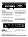
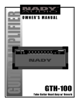
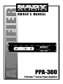
OWNER’S MANUAL
PPA-300
ProPower™ Stereo Power Amplifier
PPA-300
ProPower™ Stereo Power Amplifier
Congratulations on your choice of the NADY AUDIO ProPower™ PPA-300 stereo power amplifier — you have purchased one
of the finest stereo amplifiers on the market today. This unit was developed using the expertise of professional sound engineers
and working musicians. You will find that your new PPA-300 amplifier has superior performance and greater flexibility than any
other amplifiers in its price range. Please read this manual carefully to get the most out of your new unit. Thanks for selecting
NADY AUDIO as your choice in stereo power amplifiers.
F E AT U R E S
Offering top power, superior performance and full professional operating features in a roadworthy compact chassis, the PPA-300
amplifier is perfect for even the most demanding sound reinforcement installation and touring applications.
• Full operating features: stereo (dual channel), volume controls; XLR and 1/4” TS inputs
• Full safety/reliability features: fan for cooling; soft-start turn on, noise-free on-off; built-in DC offset; independent DC and thermal overload
protection on each channel; short circuit and speaker protection
• Power ON LED; Signal and Clipping LED indicators for each channel
• Roadworthy, rugged double rack space (2U) housing
• IEC power cord connector with built-in fuse
• PPA-300 - 2 x 150W RMS @ 4 Ohms, 2 x 120W RMS @ 8 Ohms
CONTENTS
FEATURES ................................................................................2
Date of Purchase
WARNING ..................................................................................3
Dealer’s Name
City
FRONT & REAR PANEL CONNECTIONS ................................4
State
INSTALLATION ..........................................................................5
Zip
CONNECTIONS ........................................................................6
Model #
SPECIFICATIONS ......................................................................7
Serial #
2
WA R N I N G
IMPORTANT SAFETY INSTRUCTIONS
When using this electronic device, basic precautions should always be taken, including the following:
1. Read all instructions before using the product.
2. Do not use this product near water (e.g., near a bathtub, washbowl, kitchen sink, in a wet basement, or near a
swimming pool, etc.).
3. This product should be used only with a cart or stand that will keep it level and stable and prevent wobbling.
4. This product, in combination with headphones or speakers, may be capable of producing sound levels that
could cause permanent hearing loss. Do not operate for a long period of time at a high volume level or at a
level that is uncomfortable. If you experience any hearing loss or ringing in the ears, you should consult an
audiologist.
5. The product should be positioned so that proper ventilation is maintained.
6. The product should be located away from heat sources such as radiators, heat vents, or other devices
(including amplifiers) that produce heat.
7. The product should be connected to a power supply only of the type described in the operating instructions or
as marked on the product. Replace the fuse only with one of the specified type, size, and correct rating.
8. The power supply cord should: (1) be undamaged, (2) never share an outlet or extension cord with other
devices so that the outlet’s or extension cord’s power rating is exceeded, and (3) never be left plugged into
the outlet when not being used for a long period of time.
9. Care should be taken so that objects do not fall into, and liquids are not spilled through, the enclosure’s
openings.
10. The product should be serviced by qualified service personnel if:
A.
The power supply cord or the plug has been damaged.
B.
Objects have fallen into, or liquid has been spilled onto the product.
C. The product has been exposed to rain.
D.
The product does not appear to operate normally or exhibits a marked change in performance.
E.
The product has been dropped, or the enclosure damaged.
11. Do not attempt to service the product beyond what is described in the user maintenance instructions. All
other servicing should be referred to qualified service personnel.
3
FRONT & REAR CONTROLS AND CONNECTIONS
(4) (4)
(5) (3) (2) (3) (5)
(1)
power amplifier’s level controls or reduce the output level
of the preceding component to avoid audible distortion or
hard clipping. (Note: Operating the amplifier at hard
clipping can result in overheating or may damage your
amplifier over a period of time. Amplifiers that are
damaged due to such user neglect, or improper
operation, are not covered under warranty.)
FRONT PANEL
1. POWER SWITCH
To turn the unit ON or OFF, press the left or right portion
of this button. Before turning on the amplifier, check all
connections and turn down the level controls. A
momentary muting is normal when turning the amplifier
on or off. (Caution: Always turn on your power amplifier
last, after all your other connected equipment, and
always turn off your power amplifier before your other
connected equipment.)
4. SIGNAL LED INDICATORS
These LEDs illuminate to confirm the presence of an
input signal greater than 100 mV at that channel of the
amplifier
2. POWER LED INDICATOR
This LED flashes and then illuminates when the power is
turned “ON”.
5. LEVEL CONTROLS
These control the level of signal coming into each
channel. The actual voltage gain of the amplifier is
shown in dB. Turn these controls counterclockwise if the
peak LEDs illuminate steadily (indicating too strong an
input signal).
3. CLIP (PEAK) LED INDICATORS
These LEDs illuminate if any section of the power
amplifier’s output are within 3dB of clipping. Occasional
blinking of the LEDs are acceptable, but if they remain on
more than occasionally you should turn down either the
(8)
(6) (7)
(9)
REAR PANEL
8. L/R CHANNEL OUTPUT CONNECTORS
1/4” (6.3 mm) speaker output jacks. Connect these to
speakers with a total impedance of no less than 4 ohms
per side.
6. POWER CONNECTOR
The cord connector is used to connect the AC power
source to your power amplifier. (CAUTION: DO NOT
REMOVE THE CENTER GROUNDING PIN.)
9. BALANCED INPUT CONNECTORS (1/4" TS & XLR)
1/4" (6.3mm) TS (Tip/Sleeve) phone jacks and XLR
jacks.
7. FUSE
If this fuse blows continuously, shut off the unit and have
it serviced by qualified service technician. 115V AC ~5A
250V FB
4
I N S TA L L AT I O N
To ensure years of enjoyment from your NADY AUDIO ProPower™ PPA-300, please read and understand this manual
thoroughly before using the unit.
INSPECTION
Your NADY AUDIO ProPower™ PPA-300 was carefully packed at the factory in packaging designed to protect the units in
shipment. Before installing and using your unit, carefully examine the packaging and all contents for any signs of physical
damage that may have occurred in transit.
[Please note: Nady Systems is not responsible for shipping damage. If your unit is damaged, do not return to Nady, but notify
your dealer and the shipping company (if shipped to you) immediately to make a claim. Such claims must be made by the
consignee in a timely manner.]
CONTENTS
• Instruction manual
• PPA-300 (verify that the unit’s serial number is same as shown on shipping carton)
• AC Power cord
• Warranty Card
POWER CONNECTION
The PPA-300 has an internal power supply and is designed to operate from an external AC source. Power requirements
for electrical equipment differ from area to area. Be sure to confirm that the voltage is your area is 115V, 60 Hz
RACK MOUNTING
The PPA-300 amplifier is designed for standard 19" rack mounting as well as “stack” mounting without a cabinet. Use 4
screws and washers for mounting to the front rack rails. It is also a good idea to support the amps also in the rear,
especially for mobile use where the amps will be subjected to shocks.
AMPLIFIER COOLING
Also pay close attention to the cooling requirements. Never block the air vent in the back side and front of the amplifier if
the amplifier is being run at high output levels. For best results in such high output power applications you should
augment the amplifier’s air flow with a rack cooling system.
5
CONNECTIONS
Total impedance
no less than 4
Total impedance
no less than 4
or
or
6
S P E C I F I C AT I O N S
POWER SPECIFICATIONS
OUTPUT POWER (EIA 1KHz 1% THD) ..........................................................................120W RMS @ 8 ohms per side
150W RMS @ 4 ohms per side
ELECTRICAL SPECIFICATIONS
INPUT SENSITIVITY ...........................................................................................................................500V RMS (-4dBu)
INPUT IMPEDANCE ..........................................................................................................50K Unbalanced & Balanced
FREQUENCY RESPONSE (at 10dB below rated output power) ........................................................20Hz~20KHz ±1dB
5Hz~50KHz ±3dB
DISTORTION ..............................................................................................................................................................<.1%
S/N RATIO ................................................................................................................................................................100dB
GENERAL SPECIFICATIONS
PROTECTIONS ......................................................................Full short circuit, open circuit, thermal, ultrasonic, and RF
protection; stable into reactive or mismatched loads; ON/OFF muting; current limiter
FRONT CONTROLS ............................................................................Power switch, input level control for each channel
REAR PANEL CONTROLS ......................................................................................................AC voltage selector switch
CONNECTORS ......................................................................................................................Power; IEC power cord jack
Input: Active balanced XLR and 1/4” (6.3mm) TRS
Output: dual 1/4” speaker jacks
POWER SUPPLY ..................................................................................................................................110V~120V 60 HZ
FUSE ............................................................................................................................................115V AC ~ 5A 250V FB
DIMENSIONS ..........................................................................................................19” x 9.6” x 3.5” (483 x 244 x 89 mm)
WEIGHT ....................................................................................................................................................16.6 lbs. (7.5Kg)
The specifications above are correct at the time of printing of this manual. For improvement purposes, all specifications for this unit, including design
and appearance, are subject to change without prior notice.
7
SERVICE FOR YOUR NADY AUDIO PRODUCT
(U.S.) Should your NADY AUDIO product require service, please contact the Nady Service Department via
telephone at (510) 652-2411, or e-mail at [email protected].
(International) For service, please contact the NADY AUDIO distributor in your country through the dealer from
whom you purchased this product.
DO NOT ATTEMPT TO SERVICE THIS UNIT
YOURSELF AS IT CAN BE DANGEROUS
AND WILL ALSO VOID THE WARRANTY.
NADY SYSTEMS, INC. • 6701 SHELLMOUND STREET, EMERYVILLE, CA 94608
Tel: 510.652.2411 • Fax: 510.652.5075 • nady.com