1
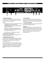
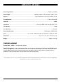
GUITAR AMPLIFIER
OWNER’S MANUAL
GTA-1260
Classic Tube AMP with Reverb
GTA-1260
Classic Tube AMP with Reverb
Congratulations on your choice of guitar amplifier —
you have purchased one of the finest guitar amplifiers
on the market today. This unit was developed using the
expertise of professional sound engineers and working
musicians. You will find that your new NADY AUDIO
GTA-1260 has superior performance and greater
flexibility than any other guitar amplifiers in its price
range. Please read this manual carefully to get the
most out of your new unit.
Thanks for selecting NADY AUDIO as your choice in
guitar amplifier.
F E AT U R E S
• All-tube design featuring two 6L6GC power and three
12AX7A preamp tubes
• Spring reverb with adjustable control and switchable with
optional FS-1 footswitch
• 60W RMS output
• Classic retro look with attractive wood grain cabinet
finish
• 12” Nady PowerDrive™speaker by Celestion
• Classic tube type tone controls
• Full complement of controls for total volume, tone
shaping and tonal definition, including 3-way overdrive
gain switch, volume, master, treble, mid, bass and
presence controls
CONTENTS
FEATURES ................................................................................2
Date of Purchase
WARNING ..................................................................................3
Dealer’s Name
City
INSTALLATION ..........................................................................4
State
LEGAL INFORMATION..............................................................4
Zip
FRONT CONTROL AND CONNECTORS ................................5
Model #
REAR CONTROL AND CONNECTORS ..................................6
Serial #
SPECIFICATIONS ......................................................................7
2
WA R N I N G
An equilateral triangle enclosing a lightening flash/arrowhead symbol is
intended to alert the user to the presence of uninsulated “dangerous
voltage” within the product’s enclosure which may be of sufficient
magnitude to constitute a risk of electric shock.
ATTENTION: RISQUE DE CHOC ELECTRIQUE NE PAS OUVRIR
An equilateral triangle enclosing an exclamation point is intended to alert
the user to the presence of important operating and service instructions in
the literature enclosed with this unit.
IMPORTANT SAFETY INSTRUCTIONS
When using this electronic device, basic precautions should always be taken, including the following:
1. Read all instructions before using the product.
2. Do not use this product near water (e.g., near a bathtub, washbowl, kitchen sink, in a wet basement, or near a
swimming pool, etc.).
3. This product should be used only with a cart or stand that will keep it level and stable and prevent wobbling.
4. This product, in combination with headphones or speakers, may be capable of producing sound levels that
could cause permanent hearing loss. Do not operate for a long period of time at a high volume level or at a
level that is uncomfortable. If you experience any hearing loss or ringing in the ears, you should consult an
audiologist.
5. The product should be positioned so that proper ventilation is maintained.
6. The product should be located away from heat sources such as radiators, heat vents, or other devices
(including amplifiers) that produce heat.
7. The product should be connected to a power supply only of the type described in the operating instructions or
as marked on the product. Replace the fuse only with one of the specified type, size, and correct rating.
8. The power supply cord should: (1) be undamaged, (2) never share an outlet or extension cord with other
devices so that the outlet’s or extension cord’s power rating is exceeded, and (3) never be left plugged into
the outlet when not being used for a long period of time.
9. Care should be taken so that objects do not fall into, and liquids are not spilled through, the enclosure’s
openings.
10. The product should be serviced by qualified service personnel if:
A.
The power supply cord or the plug has been damaged.
B.
Objects have fallen into, or liquid has been spilled onto the product.
C. The product has been exposed to rain.
D. The product does not appear to operate normally or exhibits a marked change in performance.
E.
The product has been dropped, or the enclosure damaged.
11. Do not attempt to service the product beyond what is described in the user maintenance instructions. All
other servicing should be referred to qualified service personnel.
3
I N S TA L L AT I O N
To ensure years of enjoyment from your NADY AUDIO GTA-1260, please read and understand this manual thoroughly before
using the unit.
INSPECTION
Your NADY AUDIO GTA-1260 was carefully packed at the factory in packaging designed to protect the units in shipment.
Before installing and using your unit, carefully examine the packaging and all contents for any signs of physical damage
that may have occurred in transit.
[Please note: Nady Systems is not responsible for shipping damage. If your unit is damaged, do not return to Nady, but
notify your dealer and the shipping company (if shipped to you) immediately to make a claim. Such claims must be made
by the consignee in a timely manner.]
CONTENTS
• Instruction manual
• GTA-1260 (verify that the unit’s serial number is same as shown on shipping carton)
• AC Power cord
• Warranty Card
POWER CONNECTION
The GTA-1260 has an internal power supply and is designed to operate from an external AC source. Power requirements
for electrical equipment differ from area to area. Be sure to confirm that the voltage selected by the voltage selector switch
on the back panel is proper for your area (120VAC/60 Hz or 230VAC/50Hz) per the information below:
Europe (except UK): 230V, 50Hz
UK and Australia: 240V, 50Hz
USA and Canada: 120V, 60 Hz
For other areas, please check with local authorities.When ready to operate, plug the AC cord into the power source. Make
sure that the unit is turned off before connecting to the AC power source to avoid possible loud transients that can
damage your speakers or your ears, especially when monitoring with headphones.
L E G A L I N F O R M AT I O N
NOTICE
The information in this document is subject to change, as the Company may make changes to product in order to improve
reliability, design, or function, without prior written notice. No part of this manual may be reproduced or transmitted in any form
or by any means without the written permission of the company.
IN NO EVENT WILL THE COMPANY BE LIABLE FOR SPECIAL INCIDENTAL OR CONSEQUENTIAL DAMAGES,
WHETHER ARISING DIRECTLY OR INDIRECTLY, SUCH AS LOSS OF PROFIT OR GOOD WILL, THAT MAY BE
SUFFERED IN CONNECTION WITH THE PURCHASE OF THIS PRODUCT OR FROM THE BREACH OF ANY
REPRESENTATION OR WARRANTY.
LICENSE
The Company grants the customer a non-exclusive, non-transferable license to use the software, if any, accompanying this
product for internal use on a single computer system. The end user may make a single copy of the software solely for backup
purposes; otherwise, no copies may be made of the software or any part thereof. No other license of any kind is granted to
any part of the product or any of the intellectual property therein.
4
FRONT CONTROLS AND CONNECTIONS
(4)
(5)
(6)
(7)
(8)
(10)
(9)
1. POWER SWITCH
This switch turns the main power on and off. Flipping the
toggle switch up to the ON+ position will turn on the amp
“in phase” with the main AC line voltage. Flipping the
switch down to the ON- position will reverse the polarity.
In some cases, AC hum (caused by ground loops) can be
reduced by reversing the polarity. Select the On position
which has the least amount of AC hum.
(11)
(12)
(3)
(2) (1)
• For maximum distortion adjust the VOLUME to
maximum, the MASTER to a very low setting, and
the DISTORTION to Position 3.
6. VOLUME CONTROL
This adjusts the level of the input signal to the amp.
Increasing this level will create distortion dependent on
the DISTORTION setting.
2. POWER INDICATOR LIGHT
Lights when the unit is powered on.
7. MASTER VOLUME CONTROL
Adjusts overall loudness of the amp.
3. STANDBY SWITCH
Flipping this toggle switch to ON/OFF (STBY) will
respectively enable/disable the audio to the amplifier and
the outputs. This allows for proper warm-up of the tubes
before applying signal to them, and allows the amp to stay
warm when not in immediate use. To extend the life of
the tubes, always turn the Main Power Switch on first, for
1-2 minutes, before flipping ON the Standby Switch.
8. TREBLE CONTROL
Adjusts the level of treble/Hi frequencies.
9. MID CONTROL
Adjusts the level of mid-range frequencies.
10. BASS CONTROL
Adjusts the level of bass frequencies.
4. INPUT JACK
Input for instrument outputs — guitar, keyboard, highoutput mics for harmonicas, and other effects devices.
11. PRESENCE CONTROL
Adjusts the high overtones, texture, and feel of the amp.
5. DISTORTION SELECTOR
This three-way switch selects the input sensitivity and
amount of overdrive distortion. Position 1 offers the
cleanest signal with least amount of distortion. Position 3
has the maximum amount of distortion.
12. REVERB CONTROL
Adjusts the level of reverb mixed with the dry signal.
Note: The VOLUME and MASTER controls also affect
the final signal level and the amount of distortion.
• For cleanest operation (least distortion) adjust the
VOLUME to a very low setting, the MASTER to
maximum, and the DISTORTION to Position 1.
• For medium distortion ( or crunch) adjust the
VOLUME to past the mid position, the MASTER to
mid, and the DISTORTION to Position 2.
5
REAR CONTROLS AND CONNECTIONS
(1)
(2)
(4)
(3)
(5)
(6)
1. POWER CONNECTION
A standard IEC AC power socket for connecting to the
main AC supply. The IEC power socket has an integral
fuse holder that takes a 20mm fuse.
4. SPEAKER JACK
This jack is connected to the internal speaker using a “L”
shaped plug and speaker cable. The internal speaker can
be disconnected if you wish to only use external speakers.
NOTE:
• Always replace a blown fuse with the same type as
specified on the rear panel and under
SPECIFICATIONS (pg. 7) for the AC voltage being
used to power the amp
5. EXTERNAL SPEAKER
Jack for connecting external speakers. For optimum output
power, these should be 8Ω minimum.
6. LINE OUT
This line level output signal is derived from the output of
the power amp to incorporate all the characteristics, color
and tonal response of the output tubes. This signal can be
input into any device, such as an audio mixer or another
amplifier, and can be useful in many lives sound or
recording applications.
• Before you connect your GTA-1260 to the AC,
please make sure that your local voltage matches
the voltage required by the unit!
• Do not remove the center ground conductor.
2. VOLTAGE SELECTOR SWITCH
For selecting the proper voltage (115/230VAC) to match
the power supply in your area.
3. REVERB FOOTSWITCH JACK
For connecting an optional external footswitch to turn the
reverb on and off. See your dealer for ordering the Nady
FS-1 footswitch, or order directly from Nady with the
included ordering form.
If reverb footswitch jack is not used for switching. a pure
reverb line level signal is present at the jack. This may be
used for stereo effects with an outboard amp and speaker
or plugged into mixing consoles and tape machines for
recording. The output at F.S. Jack is sleeve GND, TIP
HOT +
6
S P E C I F I C AT I O N S
Power Amp Section ..............................................................................................................................Tubes: 2 ea 6L6GC
Power Output........................................................................................60 Watts @ 8Ω 5% THD; 40 Watts @ 4Ω 5% THD
Speaker ....................................................................................................Nady PowerDrive™ PD-12i by Celestion, 12” 8Ω
Preamp Section....................................................................................................................................Tubes: 3 ea 12AX7A
Input Imp. .................................................................................................................................................................. 200KΩ
Input Sens. .................................................................................................. Max clean 800Mv 1KHz; Max dist. 8Mv. 1KHz
Line Out Inp. ................................................................................................................................................................ 600Ω
Line Out Level .................................................................................................................................................... 1V Nominal
Power Requirements ............................................................................................................ 115VAC/60Hz; 230VAC/50Hz
Fuse ............................................................................ For 115 VAC: 3 AMP S.B. 250V; For 230 VAC: 1.5 AMP S.B. 250V
Dimension .......................................................................................................... 18.3” x 9” x 17.5” (46.5 x 22.9 x 44.5 cm)
Weight ...................................................................................................................................................... 45.6 lbs. (20.7 kg)
TUBE REPLACEMENT
Preamp Tubes 12AX7A — No adjustment required
Output Tubes 6L6GC — After replacing output tubes, output tubes bias voltage should be checked with Standby switch
set to On, no signal input, and all controls set to minimum. If output tube bias voltage is not correct, amplifier will sound
unusually distorted with mushy audio and output tubes may overheat. Normal output tube bias voltage should be —
52VDC on Pin 5 of all output tubes. For best results use matched output tubes.
The specifications above are correct at the time of printing of this manual. For improvement purposes, all specifications for this unit, including design
and appearance, are subject to change without prior notice.
7
SERVICE FOR YOUR NADY AUDIO PRODUCT
(U.S.) Should your NADY AUDIO product require service, please contact the Nady Service Department via
telephone at (510) 652-2411, or e-mail at [email protected].
(International) For service, please contact the NADY AUDIO distributor in your country through the dealer from
whom you purchased this product.
DO NOT ATTEMPT TO SERVICE THIS UNIT
YOURSELF AS IT CAN BE DANGEROUS
AND WILL ALSO VOID THE WARRANTY.
NADY SYSTEMS, INC. • 6701 SHELLMOUND STREET, EMERYVILLE, CA 94608
Tel: 510.652.2411 • Fax: 510.652.5075 • nady.com