1
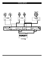
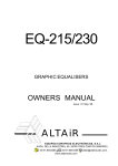
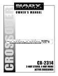
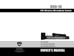
CROSSOVER
OWNER’S MANUAL
CX-22SW
2-WAY STEREO PLUS SUBWOOFER
CX-22SW
2-WAY STEREO+SUBWOOFER CROSSOVER
Congratulations on your choice of crossover — you have
purchased one of the finest stereo crossovers on the market today. This unit was developed using the expertise of
professional sound engineers and working musicians. You
will find that your new NADY AUDIO CX-22SW has superior performance and greater flexibility than any other
crossovers in its price range. Please read this manual
carefully to get the most out of your new unit.
Date of Purchase
Dealer’s Name
City
State
Zip
Model #
Thanks for selecting NADY AUDIO as your choice in
crossovers.
Serial #
FEATURES
CONTENTS
Crossovers provide precise frequency dividing for multiamplified speaker applications, and are valuable tools in
many professional live sound uses. The CX-22SW offers
2-way active LOW/HIGH outputs for each stereo channel
and a mono subwoofer output. It is simple to set up and
operate and is the perfect choice for basic multi-amps,
multi-speaker stereo installations.
•
•
•
•
•
•
Features ......................................................................2
Warning ......................................................................3
Controls and Connections ..........................................4
Specifications ..............................................................5
Typical Set-up..............................................................6
Single rack space (1U)
Shielded internal power supply with AC voltage select
switch (~115V/60Hz or ~230V/50Hz)
Phase inversion switches
Low-cut subsonic filters for low frequency
driver protection
Servo-balanced XLR inputs
Superior performance with transparent audio
2
WARNING
An equilateral triangle enclosing a lightning flash/arrowhead symbol is
intended to alert the user to the presence of uninsulated “dangerous
voltage” within the product’s enclosure which may be of sufficient
magnitude to constitute a risk of electric shock.
ATTENTION: RISQUE DE CHOC ELECTRIQUE NE PAS OUVRIR
An equilateral triangle enclosing an exclamation point is intended to alert
the user to the presence of important operating and service instructions in
the literature enclosed with this unit.
IMPORTANT SAFETY INSTRUCTIONS
When using this electronic device, basic precautions should always be taken, including the following:
1. Read all instructions before using the product.
2. Do not use this product near water (e.g., near a bathtub, washbowl, kitchen sink, in a wet basement, or near a
swimming pool, etc.).
3. This product should be used only with a cart or stand that will keep it level and stable and prevent wobbling.
4. This product, in combination with headphones or speakers, may be capable of producing sound levels that
could cause permanent hearing loss. Do not operate for a long period of time at a high volume level or at a
level that is uncomfortable. If you experience any hearing loss or ringing in the ears, you should consult an
audiologist.
5. The product should be positioned so that proper ventilation is maintained.
6. The product should be located away from heat sources such as radiators, heat vents, or other devices
(including amplifiers) that produce heat.
7. The product should be connected to a power supply only of the type described in the operating instructions or
as marked on the product. Replace the fuse only with one of the specified type, size, and correct rating.
8. The power supply cord should: (1) be undamaged, (2) never share an outlet or extension cord with other
devices so that the outlet’s or extension cord’s power rating is exceeded, and (3) never be left plugged into
the outlet when not being used for a long period of time.
9. Care should be taken so that objects do not fall into, and liquids are not spilled through, the enclosure’s
openings.
10. The product should be serviced by qualified service personnel if:
A.
The power supply cord or the plug has been damaged.
B.
Objects have fallen into, or liquid has been spilled onto the product.
C. The product has been exposed to rain.
D. The product does not appear to operate normally or exhibits a marked change in performance.
E.
The product has been dropped, or the enclosure damaged.
11. Do not attempt to service the product beyond what is described in the user maintenance instructions. All
other servicing should be referred to qualified service personnel.
3
CONTROLS AND CONNECTIONS
3
2
4
6
5
7
2
4
3
8
5
1
FRONT PANEL
1.
POWER SWITCH
To turn the unit ON or OFF, press the upper or lower
portion of this button. The internal power LED illuminates
when the unit is turned “ON”. (Caution: Always turn the
Crossover ON before the amplifier, and turn it OFF after
the amplifier or transients harmful to the speakers
may result.)
PLEASE READ THIS MANUAL
BEFORE OPERATING THIS UNIT
Caution : To prevent malfunctioning
and/or possible equipment damage:
Before plugging the unit into the power
source: (1) the voltage selector switch
should be set for the correct voltage for
your area (115V or 230V) and (2) all
equipment connected to the crossover
outputs should be turned off or all the
inputs turned down.
2.
CROSSOVER FREQUENCY CONTROLS:
These select the crossover frequencies of the LOW and
HIGH ways. They’re a low cut for the HIGH and a high
cut for the LOW. You can select the frequencies
between 250 Hz and 6 Hz.
3.
L/H OUTPUT LEVEL CONTROLS:
These are used to adjust the output level of each way: LOW and HIGH .
4.
LOW CUT BUTTONS FOR LOW WAY:
These insert low cut filters in the LOW way of each stereo channel with a 12dB/Octave, 30 Hz HPF
to minimize problems from subsonic frequencies in the signal, to suppress hum, and to prevent low
frequency speaker resonance.
5.
PHASE BUTTONS:
These allow switching the polarity to invert the signal phase on the HIGH ways. This is done after
the output levels are set to correct audible phase problems.
Caution: Before pressing the PHASE BUTTON, always lower the outputs of your power amplifiers
to avoid possible speaker damage.
6.
SUB CROSSOVER FREQUENCY CONTROL:
This selects the crossover frequency of the SUB WOOFER way. You can select the frequency
between 50 Hz to 250 Hz.
7.
SUBWOOFER OUTPUT LEVEL CONTROL:
This is used to adjust the SUB WOOFER output level.
8.
SUBWOOFER LOW CUT BUTTON:
This inserts a low cut filter in the SUBWOOFER way with a 12dB/Octave, 30 Hz HPF to minimize
problems from subsonic frequencies in the signal, to suppress hum, and to prevent low frequency
subwoofer speaker resonance.
4
CONTROLS AND CONNECTIONS
XLR
BALANCE D
PIN 1 GND
PIN 2 HI
PIN 3 LO
PHONE UNBAL
115V/60Hz
230V/50Hz
L CHANNEL
SUB
NADY SYSTEMS, Inc.
Emeryville, CA, USA
Made in Taiwan
AC IN
FUSE 0.5A
12
R CHANNEL
13
9
HIGH
OUTPUT
11
LOW
INPUT
WOOFER
10
HIGH
11
OUTPUT
LOW
11
INPUT
10
REAR PANEL
9.
FUSE COMPARTMENT:
Replace with only the same type fuse (0.5A/250V). If it blows continuously, do not use the unit
until it has been serviced by qualified personnel.
10.
STEREO INPUT CONNECTORS:
Connect your L/R stereo input signal to either the balanced XLR or the unbalanced 1/4" phone jacks.
11.
OUTPUT CONNECTORS:
Connect to your amplifiers via these unbalanced 1/4" phone jacks.
12.
AC VOLTAGE SELECTOR SWITCH:
Before plugging in the power cord, check to see that the unit is set for the proper voltage for your
area:~115V (60Hz) or ~230V (50Hz).
13.
POWER CONNECTOR
The IEC jack is used to connect the power cord to the AC Power Source.
(Caution: Do not remove the center grounding pin.)
SPECIFICATIONS
Crossover Type ..............................................................Stereo 2 ways + Subwoofer
Crossover Range ............................................................Subwoofer: 50 - 250Hz, -24/10dB
Low/High : 250-6000Hz, -24/10dB
Filter Type (Slope) ..........................................................2nd order, 12dB/Octave
Inputs
Type ..............................................................................Balanced XLR and unbalanced 1/4"
Impedance ....................................................................100KΩ
Outputs
Type ..............................................................................Unbalanced 1/4"
Impedance ....................................................................220 Ω
Low Cut Filters................................................................30Hz/ - 3dB, 12dB/Octave
Frequency Response......................................................20Hz - 25KHz +/-1dB
Total Harmonic Distortion (THD) + Noise ....................< 0.05 %
S/N Ratio ..........................................................................> 95 dB
Fuse..................................................................................0.5 A/ 250V, 5mm glass type
Dimensions......................................................................19’’ x 1.73’’ x 5.9’’ (483 X 44 X 150mm)
Weight ..............................................................................4.4 lbs. (2.2 Kg)
Specifications and design subject to change without prior notice for improvement purposes
5
TYPICAL SET-UP
6
SERVICE FOR YOUR NADY AUDIO PRODUCT
(U.S.) Should your NADY AUDIO product require service, please contact the Nady Service Department via telephone at (510) 652-2411, or e-mail at [email protected].
(International) For service, please contact the NADY AUDIO distributor in your country through the dealer from
whom you purchased this product.
DO NOT ATTEMPT TO SERVICE THIS UNIT
YOURSELF AS IT CAN BE DANGEROUS
AND WILL ALSO VOID THE WARRANTY.
NADY SYSTEMS, INC. • 6701 SHELLMOUND STREET, EMERYVILLE, CA 94608
Tel: 510.652.2411 • Fax: 510.652.5075 • www.nadywireless.com