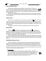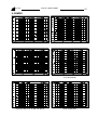
1
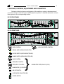
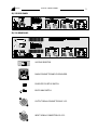
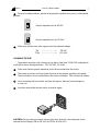
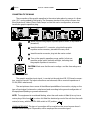
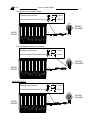
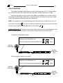
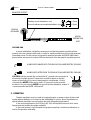
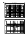
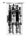
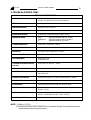
EQ-215/230
GRAPHIC EQUALISERS
OWNERS MANUAL
issue 1.0 May 98.
ALTAiR
EQUIPOS EUROPEOS ELECTRÓNICOS, S.A.L.
AVDA. DE LA INDUSTRIA, 50. 28760 TRES CANTOS (MADRID)
34-91-8043265
34-91-8044358
www.altairaudio.com
[email protected].
ALTAiR
EQ-215/230 GRAPHIC ECUALISERS
2
CONTENTS
1. INTRODUCTION
2. SWITCHES, CONTROLS, ADJUSTMENTS AND CONNECTORS
EQ-215 FRONT PANEL
EQ-230 FRONT PANEL
EQ-215 REAR PANEL
EQ-230 REAR PANEL
3. WORKING PRECAUTIONS
4. INSTALLATION
UNPACKING
MOUNTING
CHANGING THE VOLTAGE
CHANGING THE FUSE
CONNECTION TO THE MAINS
INPUT CONNECTION
UNBALANCED INPUT
BALANCED INPUT
OUTPUT CONNECTION
UNBALANCED OUTPUT
BALANCED OUTPUT
GROUND LINK
5. OPERATION
TURN ON DELAY CIRCUIT
LEVEL CONTROL
SIGNAL AND OVERLOAD INDICATOR
HIGH PASS FILTER CONTROL
BYPASS SWITCH
RANGE SWITCH
PARAMETRIC FILTER (ONLY EQ-230)
GAIN CONTROL:
FREQUENCY SWITCH x10:
FREQUENCY CONTROL:
BANDWIDTH (Q) CONTROL:
ON/OFF SWITCH:
FADERS
FADER STATUS SWITCH
LEDs ON:
SCAN (ONLY EQ-230):
LEDs OFF:
6. SOUND SYSTEM EQUALISA TION
7. BLOCK DIAGRAM AND HOW IT WORKS
8. TECHNICAL SPECIFICA TIONS
9. GRAPHS
10. WARRANTY
3
4
4
4
5
5
6
6
6
6
6
7
8
8
8
9
10
10
11
11
11
12
12
12
13
13
13
13
13
14
14
14
14
14
14
16
16
16
16
17
19
20
21
ALTAiR
EQ-215/230 GRAPHIC ECUALISERS
3
1. INTRODUCTION
Congratulations on your purchase of a ALTAIR graphic equaliser. Our dilated experience in the design and manufacture of low signal equipment culminate with the presentation
of this new generation of graphic equalisers.
There is a lot of characteristics that makes the ALTAIR graphic equalisers, one of the
most highlighted on the audio professional market, here follows some of them:
Constant (Q) design
The constant bandwidth (Q) allows a greater control in the band adjustment, since the
filter affects to the same portion of band independently of the frequency and/or gain
adjustment.
Equalisation range selector
The equalisation range selector allows to setup the filters gain/attenuation range
between ±6 and ±12 dB, which allows a greater precision in the equaliser adjustment.
FFS Feedback finder system (only EQ-230)
Each band has a LED indicator on each fader, by means of which the equaliser
indicated the band where it find the feedback. This system helps to the sound technician in the
soundcheck, to find the bands sensitive to produce feedbacks.
Parametric/notch filter in each channel (only EQ-230)
The parametric filter allows a point of equalisation in each channel, in which the user
can setup the frequency, the gain and the bandwidth (Q). In its minimum bandwidth (Q)
position it becomes a notch filter, is to say a filter that allows to eliminate feedbacks or an
annoying 50-60 stage hum, removing the minimum amount of frequency response.
Naturally, you want to use your graphic equaliser soon, but first, it is important that you
read this manual. This manual help you to install and use your new graphic equaliser properly.
It is very important that you read it carefully, mainly the paragraphs marked as NOTE, CAUTION
and DANGER, for your security
Save the original packing for the future, so you could use it to transport the graphic
equaliser. NEVER SHIP THE GRAPHIC EQUALISER WITHOUT IT'S ORIGINAL PACKING.
ALTAiR
4
EQ-215/230 GRAPHIC ECUALISERS
2. SWITCHES, CONTROLS, ADJUSTMENTS AND CONNECTORS
Following is the front/rear panel drawing of the switches, controls, adjustments and
connectors that you could find in your ALTAIR graphic equaliser. A detailed explanation of each
item appears in the corresponding section.
EQ-215 FRONT PANEL
EQ-230 FRONT PANEL
LEVEL CONTROL.
HIGH PASS FILTER CONTROL .
SIGNAL AND OVERLOAD INDICATOR.
BYPASS SWITCH (WITH INDICATOR LED).
RANGE SWITCH (WITH INDICATOR LED).
GAIN CONTROL.
FREQUENCY SWITCH.
FREQUENCY CONTROL.
}
BANDWIDTH (Q) CONTROL.
ON/OFF SWITCH.
FADER (WITH INDICATOR LED).
POWER SWITCH.
PARAMETRIC FILTER (ONLY EQ-230).
ALTAiR
EQ-215/230 GRAPHIC ECUALISERS
EQ-215 REAR PANEL
EQ-230 REAR PANEL
VOLTAGE SELECTOR.
MAINS CONNECTOR AND FUSE HOLDER.
FADER STATUS SETUP SWITCH.
EARTH LINK SWITCH.
OUTPUT SIGNAL CONNECTOR XLR-3-32.
INPUT SIGNAL CONNECTOR XLR-3-31.
5
ALTAiR
EQ-215/230 GRAPHIC ECUALISERS
6
3. WORKING PRECAUTIONS
The manufacturer is not responsible of any damage occurred in the graphic equaliser
unit outside the limits of the warranty or those produced by not keeping in mind the working
precautions.
Always operate the unit with the AC ground wire connected to the electrical
system ground. Precautions should be taken so that the means of grounding of a
piece of equipment is not defeated.
Mains voltage must be correct and the same as that setting on the rear of the unit
voltage switch. Damage caused by connection to improper AC voltage is not covered by any warranty.
DANGER: Do not remove the cover. Removing the cover will expose you to
potentially dangerous voltages. There are no user serviceable parts inside.
CAUTION: Protect the graphic equaliser unit from the rain and humidity. Ensure
that no objects or liquids enter it. If a liquid is spilled into the graphic equaliser,
disconnect the graphic equaliser from the mains and consult a qualified technical
service.
Don't place the graphic equaliser unit close to heat sources.
Equipment should be serviced by qualified personnel when:
The power supply cord/plug is damaged
Any object have fallen or liquid has been spilled into the equaliser.
The unit does not appear to operate properly.
The enclosure is damaged.
4. INSTALLATION
UNPACKING
Before leaving from factory, each graphic equaliser was carefully inspected and tested.
Unpack and inspect the graphic equaliser for any damage that may have occurred during
shipment. If any damage is found, doesn't connect the graphic equaliser to the mains,
contacts with the salesman immediately, because the unit must be inspected by a qualified
technical service.
Save the original packing, you could use if you need to transport the graphic equaliser.
NEVER SHIP THE GRAPHIC EQUALISER WITHOUT IT'S ORIGINAL PACKING.
MOUNTING
It is always advisable mount the graphic equalisers in rack, either for mobile or fixed
installations, for protection, safety, aesthetics, etc.
The graphic equalisers are designed for standard 19" rack mounting, and occupy 2u
(EQ-215) or 3u (EQ-230) rack space.
CHANGING THE VOLTAGE
The graphic equaliser unit is set to operate at 230VAC, 50-60Hz and at 115 VAC, 5060Hz. Unless specified the unit is set to 230 VAC.
1 Make sure that the graphic equaliser unit is disconnected from the mains.
ALTAiR
7
EQ-215/230 GRAPHIC ECUALISERS
2 Set up the voltage selector, placed at the graphic equaliser rear panel, in the desired
position.
Graphic equaliser set up 115 VAC.
Graphic equaliser set up 230 VAC.
3
Make sure that the fuse is the right one for the selected voltage:
T1A
------------------->
T0,5A ------------------->
115 VAC.
230 VAC.
CHANGING THE FUSE
The graphic equaliser unit is factory set up with a slow blow T0,5A FUSE, adequate to
4
work with a mains voltage between 220-240 VAC, 50-60 Hz.
1
Make sure that the graphic equaliser unit is disconnected from the mains.
2
The mains connector and fuse holder is paced at the graphic equaliser rear panel.
The fuse holder is a box located below this mains connector. Take out the fuse holder.
3
Upon extracting the fuse holder, the fuse will appear. Remove it and change for
a new one.
4
Insert the fuse holder into the mains connector again.
CAUTION: Always make sure upon changing the fuse, that this is the adequate for the
selected mains voltage (T1A for 115 VAC and T0,5A for 230 VAC).
ALTAiR
8
EQ-215/230 GRAPHIC ECUALISERS
CONNECTION TO THE MAINS
The connection of the graphic equaliser to the mains takes place by means of a threewire I.E.C. cord provided by the factory. The European standard color code is: Brown-Live,
Blue-Neutral and Yellow/Green-Earth, keeps in mind this mains configuration, whenever
handle the graphic equaliser plug.
1 Make sure that the graphic equaliser power switch, is at position 0
(turned off).
2 Insert the female I.E.C. connector plug into the graphic
equaliser male connector, placed at the rear panel.
3 Insert the male connector plug into the mains socket.
4 Turn on the graphic equaliser power switch. In that moment the range switch indicator will light, indicating that
the graphic equaliser is turned on.
CAUTION: Make sure that the mains voltage and the fuse ratings are
correct.
INPUT CONNECTION
The graphic equaliser input signal, is carried out through two XLR-3-31 female connectors, one per channel. The input connections are balanced, with a nominal impedance of
20 KΩ (10KΩ unbalanced).
The next pictures shows some of the different possibilities of connection, relying on the
type of input signal, balanced or unbalanced and according to the ground configuration of
the equipment (floating or ground-referenced).
NOTE: The equipment is considered floating, when the earth mains is lifted (is to say has a
mains plug of this form:
), or when it is lifted the electrical ground of the unit from the earth
mains (is to say, with the EARTH-LINK switch in OFF position:
).
UNBALANCED INPUT: This type of connection will be used when the sound source doesn't
provide balanced output. If it possible, will be employed the connection type 1.
ALTAiR
9
EQ-215/230 GRAPHIC ECUALISERS
1) Using twin-lead shielded cable:
Floating sound source
(
/
) : Close.
Ground-referenced sound source (
/
) : Open.
-
GRAPHIC
EQUALISER
-
GRAPHIC
EQUALISER
-
GRAPHIC
EQUALISER
+
+
SOUND
SOURCE
2) Using single conductor coax cable:
Floating sound source
(
/
) : Close.
Ground-referenced sound source (
/
) : Open.
+
SOUND
SOURCE
+
BALANCED INPUT:
Floating sound source
(
/
) : Close.
Ground-referenced sound source (
/
) : Open.
+
SOUND
SOURCE
+
-
ALTAiR
10
EQ-215/230 GRAPHIC ECUALISERS
OUTPUT CONNECTION
The graphic equaliser output signal is carried out through two XLR-3-32 male connectors, one per channel. The outputs are balanced, with a nominal impedance of 100Ω.
The following graphics shows some of the different possibilities of connection, relying
on the type of output signal, balanced or unbalanced and according to the ground configuration of the equipment (floating or ground-referenced).
NOTE: The equipment is considered floating, when the earth mains is lifted (is to say has a
mains plug of this form:
), or when it is lifted the electrical ground of the unit from the earth
mains (is to say, with the EARTH-LINK switch in OFF position:
).
UNBALANCED OUTPUT: This type of connection will be used when the sound destination unit
doesn't provide of balanced input. If it is possible, will be used the connection type 1.
1) Using twin-lead shielded cable:
Floating sound destination unit
(
/
) : Close.
Ground-referenced sound destination unit (
/
) : Open.
GRAPHIC
EQUALISER
SOUND
DESTINATION
UNIT
+
2) Using single conductor coax cable:
Floating sound destination unit
(
/
) : Close.
Ground-referenced sound destination unit (
/
) : Open.
GRAPHIC
EQUALISER
+
SOUND
DESTINATION
UNIT
ALTAiR
11
EQ-215/230 GRAPHIC ECUALISERS
BALANCED OUTPUT:
Floating sound destination unit
(
Ground-referenced sound destintation unit (
/
) : Close.
/
) : Open.
GRAPHIC
EQUALISER
+
SOUND
DESTINATION
UNIT
GROUND LINK
In some installation, it might be necessary to isolate the graphic equaliser electric
ground, from the system mains earth, in order to avoid ground loops, that could generate
unwanted noises. For this reason, the graphic equaliser provides an EARTH-LINK switch
placed at the rear panel in order to lift the mains earth from the graphic equaliser ground.
MAINS EARTH LINKED WITH THE GRAPHIC EQUALISER ELECTRIC GROUND.
ON - OFF
MAINS EARTH LIFTED FROM THE GRAPHIC EQUALISER ELECTRIC GROUND.
ON - OFF
CAUTION: Always operate the unit with the AC ground wire connected to
the electrical system ground. Precautions should be taken so that the
means of grounding of a piece of equipment is not defeated. For this
circumstance, NEVER lift the mains earth AC ground to avoid possible
accidents. For your security, NEVER use ground isolator adapters, instead it
is recommended the EARTH -LINK switch.
5. OPERATION
Graphic equalisers may be used to increase the gain or power output of the sound
system before feedback, or to improve the intelligibility of a voice. Room equalisation or
special effects simulation is among other the more interesting applications.
In live sound applications, the FFS (only EQ-230) will help technicians to find those
frequencies that makes the system unstable.
In the next sections, we will explain the graphic equaliser controls and indicators as
well as its operation and utility.
ALTAiR
EQ-215/230 GRAPHIC ECUALISERS
12
TURN ON DELAY CIRCUIT
The ALTAIR graphic equalisers incorporates a delay circuit, consisting of a relay, which
protects the output signal from switch-on transients. This delay takes two seconds, and in the
meantime the equaliser remains in by-pass.
This delay circuit makes also possible that the equaliser remains in by-pass while it is
not switched on, and therefore, in case of breakdown, it is not necessary to take the unit
physically out of the sound system.
This by-pass is mechanical (links the output connector pins to the input connector pins
one by one). For this reason it is necessary to be careful when using distinct input/output
wiring configuration because otherwise the by-pass don't work as expected, and signal
interruption will appear on the signal path.
LEVEL CONTROL
Each graphic equaliser channel (CH-1, CH2) provides a gauged input level
control between - ∞ and +6 dB. This control is placed before the equaliser filters
and therefore, its gain adjustment will affect the headroom of the whole equaliser
circuitry. See Block Diagram for details.
SIGNAL AND OVERLOAD INDICATOR
The graphic equaliser incorporates a multipurpose signal and overload
circuit on both channels. The indicator is a tricolor LED placed at the graphic equaliser front panel.
This multipoint level circuit indicates the highest level reached inside the equaliser
circuits and warns the operator about possible problems. When the level indicator lights
green, the internal level has reached -20 dBv.(signal present led). Upon lighting the level
indicator in yellow, the internal level is 0 dBv.(nominal level). Should any internal level is near
overload (+17 dBv) the level indicator lights on red to warn the security limit has been surpassed. On that case the equaliser has a 5 dB extra dynamic reserve or headroom.
If the unit is near overload (level indicator in red color), and you want to discover in
which point is taking place, follow the next steps:
, if the level indicator remain red, decrease the level
1 Press the BYPASS switch
control
up to - ∞, otherwise continue with the next step. If the overload disappears,
we must place the level control more lower than we have before, because
the overload was in this control. If the overload persist, it is because it
has a very high input level (more than 18 dBv), because of we must lower the previous unit
in the sound system.
(only for EQ-230, for the EQ2 Turn off the parametric filter with the ON/OFF switch
215 continue with the next step.), if the overload disappears, we must place the parametric
filter with a lower gain, by means of the parametric filter gain control.
3 The overload is placed in the graphic equaliser band-pass filters , because of we
must lower the global level of the band-pass filter to avoid the overload.
ALTAiR
EQ-215/230 GRAPHIC ECUALISERS
13
HIGH PASS FILTER CONTROL
Each graphic equaliser channel provides a high pass filter of 12 dB per octave, that are used for limiting the band width for lower frequencies in the equaliser
output . The high pass filter adjustment may vary between 10 Hz and 300 Hz. In a
normal application, in that we want to have available all the audible spectrum, we shall put
the high pass filter in 10 Hz.
This filter has many applications: imitation of the telephonic sound, adjustment of the
sound system band width to the speaker band width, momentarily elimination of couplings
in low frequencies.
BYPASS SWITCH
Both channels of graphic equaliser, provides of a bypass switch
. When this switch
is pressed, the band-pass filters, the parametric filter (only EQ-230) and the high pass filter
remain unavailable, remain operative only the level control, and light a red indicator associated with this switch. If we placed the level control in the 0 dB position, we will obtain a real
in/out by-pass.
The utility of this switch is to check the equalisation effect over the sound system.
RANGE SWITCH
This switch
, setup the band-pass filters variation range
of each graphic
equaliser channel (provide one per channel). With this switch depressed, the band-pass
filters have a variation range between ±12 dB, and the corresponding ±12 LED remain lighting. When this switch is pressed, the band-pass filters have a variation range between ±6
dB, and the corresponding ±6 LED remain lighting.
The band-pass filters variation range setup by means of this switch, allow us a greater
equalization control in sound system that don't need a great gain/attenuation level by band.
while in sound system that need a greater gain/attenuation level, decrease the equalization
control.
PARAMETRIC FILTER (ONLY EQ-230)
The graphic equaliser model EQ-230, provide one parametric equalization filter (is to
say in that are adjustable the three equalization parameters: gain, frequency and bandwidth), per channel. This parametric filter is a complement to the band-pass filter, allow us
an additional equalization with a great control over it, since this equalization point allow the
adjustment of its three parameters. This three parameters are adjustable by means of three
controls and two switches, explained bellow.
GAIN CONTROL:
The parametric filter gain control, allow an adjust between +15 dB and -30
dB. In -30 dB position, and with a little bandwidth (with the bandwidth control
rotate to the right), will be setup like a notch filter, is to say a filter that allow
remove one coupling, eliminate the minimum audible band. With this control
placed at the 0 dB position, the parametric filter don't work.
ALTAiR
EQ-215/230 GRAPHIC ECUALISERS
14
FREQUENCY SWITCH x10:
This switch is associated with the parametric filter frequency control, and in combination with this allow a frequency adjustment between 32Hz and 16KHz. With this switch
unpressed, the frequency control allow a frequency adjustment between 32Hz and
1,6KHz. With this switch pressed the frequency control adjustment vary between 320Hz
and 16KHz.
FREQUENCY CONTROL:
The parametric filter frequency control, associated with the frequency control
switch, previously described, allow a frequency adjustment between 32Hz and
16KHz, this allow to cover practically the whole audible band.
BANDWIDTH CONTROL (Q):
This control allow the adjustment of the parametric filter bandwidth, is to say
the amount of band that the parametric filter cover. With the control turned to
the left (Q=0,5), the parametric filter cover a great amount of audible band,
because of the change of the filter gain will be easily appreciable by the hear, on the
other hand, with this control turned to the right (Q=10), the parametric filter cover a small
amount of audible band, because of associated with a filter gain of -30 dB constitute a
notch filter that allow remove coupling, eliminating the lesser amount of audible band.
ON/OFF SWITCH:
The parametric filter ON/OFF switch
, allow enable/disable the parametric filter. If
the parametric filter is not used, is convenient disable it with this switch, instead of to put
the gain control in the 0 dB position, since avoid the signal pass by the parametric filter
circuit, with the resulting improvement in the graphic equaliser signal to noise ratio.
FADERS
The graphic equaliser model EQ-230 provide thirty band-pass filters per channel,
separated 1/3 octave according to the I.S.O. standard and the graphic equaliser model EQ215 provide fifteen band-pass filters per channel, separated 2/3 octave according to the
I.S.O. standard. Each graphic equaliser band-pass filter is controlled by a fader control
(with indicator LED), with a variation range between ±12 dB or ±6 dB, according to the range
switch position of the corresponding channel. In the first graph of the next page we can
appreciate the graphic equaliser model EQ-230 response curve with all bands enhanced
+12 dB, and in the second graph of the next page, the graphic equaliser model EQ-230
response curve with different enhances/attenuations at 1KHz. In this second graph we can
appreciate the constant bandwidth (constant Q) of the band-pass filters, is to say, the curve
shape remain constant, and therefore for small enhance in one band, the interation with the
other ones is minimum.
FADER STATUS SWITCH
The graphic equaliser model EQ-230 provide three fader status setups: LEDs ON, SCAN
and LEDs OFF, depending on the fader status setup switch
, placed at the graphic equaliser rear panel.
The 2/3 octave model EQ-215 provide two fader status setups:: LEDs ON and LEDs
ALTAiR
EQ-215/230 GRAPHIC ECUALISERS
15
Graphic equaliser EQ-230 response curve with each one of its band enhanced at +12 dB.
Graphic equaliser model EQ-230 with different enhancements at 1KHz.
ALTAiR
EQ-215/230 GRAPHIC ECUALISERS
OFF, according to the faders state setup switch
panel.
16
, placed at the graphic equaliser rear
LEDs ON:
In this switch position, the LEDs associated with the fader, remain lighting, give rise to
a greater visibility in darkness places.
SCAN (ONLY EQ-230):
With the switch placed in this position, the graphic equaliser LED associated with the
fader light when take place a feedback (feedback finder system). When a feedback take
place, the corresponding LED associated with the near band in that the feedback is, light,
if the feedback is between two bands, the corresponding LEDs light alternating, indicating that the feedback is in a intermediate position. This feedback finder system, allow a
greater speed in the feedback elimination by the sound engineer, as well as a greater
security that the feedback is in the indicated frequency.
The feedback finder system can make a mistake with sine signals, like the generated
by wind instruments, by this the system can fail in same occasions, indicating an nonexistent feedback, on the other hand, the sound engineer must distinguish between a real
feedback an a sustain flute note, by this, the inconvenient don't cause greater problems.
LEDs OFF:
In this switch position, the LEDs associated with the fader, remains off .
6. SOUND SYSTEM EQUALISA TION
Before starting the description of the equalisation procedure, we will try to justify this
equalisation. In the real world, very few things are perfect, and the same happens to the
sound systems, and even if we had a perfect speaker, the room in which we are going to
work is nor perfect either, because the floor, the walls and the ceiling are not absorbent at
all, and they produce resonances, stationary waves and its own sound, making an imperfect
system with our perfect speaker. The open-air system have the same problem, because the
floor is in the same place, and in many cases the walls as well, and the most important of
all: the speakers are not perfect.
You must as well bear in mind that no equalisation suppress the problems caused by
reflections, stationary waves and excessive resonances.
After this explanation, before starting to equalize, if the sound system is multiamplified,
adjust the crossover controls in such a way that they produce the best way of overall response (if using an spectrum analyzer) or if you are going to equalise by ear, adjust combining the two more important factors, that is, the power and the intelligibility, that is to say, the
system must give the maximum of power and has to be intelligible.
We advise the use of an spectrum analyzer, because our ears are not reliable: our
auditive memory at long term is poor, our audition process is very adaptable, because it
adjust itself to compensate different conditions, the sound pressure level and the changes in
tone. When a change takes place, our auditive sense can detect it clearly (short term auditive
memory), but ours ears are not good remembering something at long term, specially when
there are sounds without relation between the remembering periods.
ALTAiR
EQ-215/230 GRAPHIC ECUALISERS
17
Let start to equalise. If our sound system is monoamplified, adjust the high pass filter, in
such a way that limit the bandwidth to the bandwidth that the speakers of the system can
reproduced. With this we will avoid to amplify signals which will not be reproduced and to
send signals to speakers which are not able to reproduce.
If using an spectrum analyzer, now the time has come to make the measure of the
response curve of the sound system. Remember to maker several measures and to average
them out.
Equalise till the response curve is plane, or if you do it by ear, try to get the biggest
power without loosing the intelligibility. To leave the overall response curve plane, first of all
you have to attack the big peaks, when the first one had been pulled down, find the next one
and repeat the procedure as many times as it might be necessary. When finished it, adjust
the level control to solve the gain loose.
If the peak gets on between two bands of the equaliser, then divide the difference by
both of them.
Do not try to equalise out dips in the overall response curve, unless they are quite
shallow (less than 3 dB), because the power waste used for that is very high (3 dB = 2 x
power). In any case, our audition is more sensitive to the presence of anything than to its
absence, and therefore we will hear the peaks in the response before perceiving the absence in the dips.
Once the levelling of the total curve is completed, listen to the system with music and
voice. In some cases it can be advisable a gradual attenuation in the high frequencies zone,
for instance from 1 to 3 dB per octave, starting in some point between 1 and 8 KHz.
Listen to the system for a long while, and vary the volume levels. If the total curve of the
equalization system is not right, the listening fatigue will indicate that you have not finished
yet. You have to give some more tries to leave it well.
To end, you need to known the following principle: the less equalised in the system, the
better.
7. BLOCK DIAGRAM AND HOW IT WORKS.
In the input stage, the signal is electronically unbalanced, and after that the level indicator control take the first reading point of the signal level. Later the signal crosses the level
control, and in the level control output is placed the high pass filter (H.P.F.) behind it is the
second reading point of the signal level by the level indicator control.
In the model EQ-230, the signal crosses the parametric filter controls, that provide a
gain control, a frequency control and a bandwidth control, the parametric filter ON/OFF
switch controls that the signal crosses this controls or not. Following this controls its the third
reading point of the signal level by the level indicator control.
The fifteen or thirty band-pass filters (depending of the equaliser model) of the equaliser
come below, with the equalisation range selector (±12 dB or ±6 dB). Follow this it is the BYPASS switch that take the signal after the band-pass filters or after the level control, depending on its position (ON-OFF).
Immediately after it is the last reading point of the signal level by the level indicator
control, as well as the feedback finder system (only model EQ-230), that setup by means of
the faders state setup switch, controls the fader LEDs configuration.
Lastly the signal is electronically balanced, and crosses the turn on delay relay up to the
output connector. The turn on delay relay is controlled by the turn on delay circuit, that leave
in BY-PASS the equaliser, when this is turn off, and when it is turn on for a few seconds to
avoid the turn on transients
ALTAiR
EQ-215/230 GRAPHIC ECUALISERS
18
ALTAiR
EQ-215/230 GRAPHIC ECUALISERS
19
8. TECHNICAL SPECIFICA TIONS
TECHNICAL SPECIFICATIONS
NUMBER OF BANDS:
EQ-215: - 15+15 bands, 2/3 octave, ISO standard.
EQ-230: - 30+30 bands, 1/3 octave, ISO standard.
FILTERS TYPE:
Band-pass. constant Q.
CENTRE FREQUENCIES:
Better than ±4% of nominal.
CUT/BOOST:
Selectable between ±12 and ±6 dB by means of the range switch.
HIGH PASS FILTER (HPF):
12 dB/octave, sweepable frequency 10Hz - 300Hz.
PARAMETRIC FILTER:
GAIN:
FREQUENCY:
Q:
CHANNEL SEPARATION:
Greater than 75 dB (20Hz - 20KHz).
GAIN/ATTENUATION:
+6 dB. -∞. Level control by calibrated rotatory potentiometer.
DISTORTION:
Less than 0,01% at 0 dBu (20 Hz - 20 KHz).
MAXIMUM INPUT LEVEL:
+21 dBu (with all controls flat).
INPUT IMPEDANCE:
10 KΩ unbalanced.
20 KΩ balanced.
COMMON MODE RELATION RATIO:
(C.M.R.R.):
Greater than 65 dB (20Hz - 20KHz).
MAXIMUM OUTPUT LEVEL:
+21 dBu over 600Ω (0,1% THD).
OUTPUT IMPEDANCE:
100 Ω unbalanced.
100 Ω balanced.
SIGNAL TO NOISE RATION:
Greater than 108 dB ref. +20 dBu unweighted (20Hz - 20KHz).
FREQUENCY RESPONSE:
+0, -3 dB, (20Hz - 30KHz).
POWER SUPPLY:
Selectable between 115 and 230 VAC ±12%, 50-60Hz.
NET WEIGHT:
EQ-215: - 3,5 Kg.
EQ-230: - 4,5 Kg.
DIMENSIONS:
EQ-215: - 483x89x220 mm. (19" x 3 1/2" x 8 3/4").
EQ-230: - 483x123x220 mm. (19" x 6 1/2" x 8 3/4").
POWER REQUIREMENTS:
- 30 V.A.
Adjustable between +15 and -30 dBu.
Adjustable between 32Hz and 16KHz.
Adjustable between 0,5 and 10.
NOTE: 1) 0dBu = 0,775 V;
2) EQUIPOS EUROPEOS ELECTRÓNICOS S.A.L. reserves the right to modify the technical
specifications without previous notice.
ALTAiR
20
EQ-215/230 GRAPHIC ECUALISERS
9. GRAPHS
Typical common mode relation ratio (CMRR).
Typical frequency response.
Typical total armonic distortion.
Parametric filter setup at 1 KHz with different gains
and Q (bandwidth).
High pass filter at 10, 30, 100 and 300 Hz.
Channel separation.
ALTAiR
EQ-215/230 GRAPHIC ECUALISERS
21
10. WARRANTY
This unit is warranted by Equipos Europeos Electrónicos to the original user, against
flaws in the manufacturing and in the materials, for a period of one year, starting from the
date of sale.
Flaws due to wrong use of the unit, internal modifications or accidents, are not covered
by this warranty.
There is no other warranty expressed or implicir.
Any faulty unit must be sent, to the dealer or the manufacturer. The serial number of the
unit must be included with any request for the technical service.
Equipos Europeos Electrónicos reserves the right to modify the prices or the technical
specifications without notice.
SERIAL NUMBER ...................................................
ALTAiR
EQUIPOS EUROPEOS ELECTRÓNICOS, S.A.L.
Avda. de la Industria, 50. 28760 TRES CANTOS-MADRID (ESPAÑA).
34-91-804 32 65
34-91-804 43 58
[email protected].
www.altairaudio.com
European Union
Waste Electronics Information
Unión Europea
Información sobre residuos electrónicos
Waste from Electrical and Electronic Equipment (WEEE) directive
The WEEE logo signifies specific recycling programs and procedures for
electronic products in countries of the European Union. We encourage the
recycling of our products. If you have further questions about recycling, contact
your local sales office.
Directiva sobre Residuos de Aparatos Eléctricos y Electrónicos (RAEE)
El logotipo de la Directiva RAEE se refiere a los programas y procedimientos
específicos de reciclaje para aparatos electrónicos de países de la Unión
Europea. Recomendamos el reciclaje de nuestros productos. Si tiene alguna
consulta, póngase en contacto con su Distribuidor.
Information based on European UnionEEE
W Directive2002/96/EC
Información basada en la Directiva de la unión europea RAEE 2002/96/EC y el Real Decreto 208/2005
AUDIO ELECTRONICS DESIGN
EQUIPOS EUROPEOS ELECTRÓNICOS, S.A.L
Avda. de la Industria, 50. 28760 TRES CANTOS-MADRID (SPAIN).
34-91-761 65 80
34-91-804 43 58
www.altairaudio.com
[email protected]