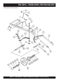
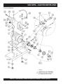
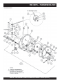
1
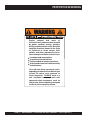
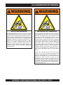
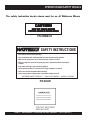
OPERATION AND PARTS MANUAL
SERIES
WM120PM Series
POLY-MECHANICAL
WM120SM Series
STEEL-MECHANICAL
PLASTER/MORTAR MIXERS
Revision #7 (09/15/11)
To find the latest revision of this
publication, visit our website at:
www.multiquip.com
THIS MANUAL MUST ACCOMPANY THE EQUIPMENT AT ALL TIMES.
PROPOSITION 65 WARNING
Engine exhaust and some of
its constituents, and some dust created
by power sanding, sawing, grinding,
drillingandotherconstructionactivities
contains chemicals known to the State
of California to cause cancer, birth
defects and other reproductive harm.
Some examples of these chemicals are:
Leadfromlead-basedpaints.
Crystallinesilicafrombricks.
Cementandothermasonryproducts.
Arsenicandchromiumfromchemically
treatedlumber.
Your risk from these exposures varies,
depending on how often you do this type
of work. To reduce your exposure to
these chemicals: ALWAYS work in a
well ventilated area, and work with
approved safety equipment, such as
dust masks that are specially designed
to filter out microscopic particles.
PAGE 2 — WM120PM/SM— OPERATION AND PARTS MANUAL — REV. #7 (09/15/11)
SILICOSIS/RESPIRATORY WARNINGS
WARNING
WARNING
SILICOSIS WARNING
RESPIRATORY HAZARDS
Grinding/cutting/drilling of masonry, concrete, metal and
other materials with silica in their composition may give
off dust or mists containing crystalline silica. Silica is a
basic component of sand, quartz, brick clay, granite and
numerous other minerals and rocks. Repeated and/or
substantial inhalation of airborne crystalline silica can
cause serious or fatal respiratory diseases, including
silicosis. In addition, California and some other
authorities have listed respirable crystalline silica as a
substance known to cause cancer. When cutting such
materials, always follow the respiratory precautions
mentioned above.
Grinding/cutting/drilling of masonry, concrete, metal and
other materials can generate dust, mists and fumes
containing chemicals known to cause serious or fatal
injury or illness, such as respiratory disease, cancer,
birth defects or other reproductive harm. If you are
unfamiliar with the risks associated with the particular
process and/or material being cut or the composition of
the tool being used, review the material safety data
sheet and/or consult your employer, the material
manufacturer/supplier, governmental agencies such as
OSHA and NIOSH and other sources on hazardous
materials. California and some other authorities, for
instance, have published lists of substances known to
cause cancer, reproductive toxicity, or other harmful
effects.
Control dust, mist and fumes at the source where
possible. In this regard use good work practices and
follow the recommendations of the manufacturers or
suppliers, OSHA/NIOSH, and occupational and trade
associations. Water should be used for dust
suppression when wet cutting is feasible. When the
hazards from inhalation of dust, mists and fumes cannot
be eliminated, the operator and any bystanders should
always wear a respirator approved by NIOSH/MSHA for
the materials being used.
WM120PM/SM — OPERATION AND PARTS MANUAL — REV. #7 (09/15/11) — PAGE 3
TABLE OF CONTENTS
Here's How To Get Help ........................................... 3
Table Of Contents .................................................... 4
Parts Ordering Procedures ...................................... 5
Operation and Safety Decals ................................... 6
Rules For Safe Operation ..................................... 7-8
Specifications ........................................................... 9
General Information ............................................... 10
Engines
Wisconsin Engine Assembly .............................40-41
Honda Engine Assembly ...................................42-43
Motor
Electric Motor Assembly....................................44-45
Transmissions
Whiteman — Plaster/ Mortar
Mixer
Transmission Assembly.....................................46-47
Terms and Conditions Of Sale — Parts ................. 48
Controls .................................................................. 11
Electric Motor ......................................................... 12
Towing .................................................................... 13
Paddle Blade Adjustment ..................................14-15
Initial Start-Up ...................................................16-17
Maintenance ..................................................... 18-19
Troubleshooting (Engine) ....................................... 20
Troubleshooting (Engine/Mixer) ............................. 21
Explanation Of Codes In Remarks Column ........... 22
Suggested Spare Parts .......................................... 23
Engine Side Paddle Assembly ..........................24-25
Tow Side Paddle Assembly ...............................26-27
Paddle Shaft Assembly .....................................28-29
Polyethylene Drum Assembly ...........................30-31
Steel Drum Assembly........................................32-33
Cab Assembly ...................................................34-35
Frame, Wheel, Tire and Hub Assembly ............ 36-37
Name Plate and Decals .................................... 38-39
NOTE
Specification and part number
are subject to change without
notice.
PAGE 4 — WM120PM/SM— OPERATION AND PARTS MANUAL — REV. #7 (09/15/11)
www.multiquip.com
PARTS ORDERING PROCEDURES
Ordering parts has never been easier!
Choose from three easy options:
Order via Internet (Dealers Only):
Best Deal!
Effective:
January 1st, 2006
If you have an MQ Account, to obtain a Username
and Password, E-mail us at: parts@multiquip.
com.
Order parts on-line using Multiquip’s SmartEquip website!
N View Parts Diagrams
N Order Parts
N Print Specification Information
To obtain an MQ Account, contact your
District Sales Manager for more information.
Use the internet and qualify for a 5% Discount
on Standard orders for all orders which include
complete part numbers.*
Goto www.multiquip.com and click on
Order Parts to log in and save!
Note: Discounts Are Subject To Change
Order via Fax (Dealers Only):
All customers are welcome to order parts via Fax.
Domestic (US) Customers dial:
1-800-6-PARTS-7 (800-672-7877)
Fax your order in and qualify for a 2% Discount
on Standard orders for all orders which include
complete part numbers.*
Note: Discounts Are Subject To Change
Order via Phone: Domestic (US) Dealers Call:
1-800-427-1244
Non-Dealer Customers:
Contact your local Multiquip Dealer for
parts or call 800-427-1244 for help in
locating a dealer near you.
International Customers should contact
their local Multiquip Representatives for
Parts Ordering information.
When ordering parts, please supply:
R
R
R
R
R
R
Dealer Account Number
Dealer Name and Address
Shipping Address (if different than billing address)
Return Fax Number
Applicable Model Number
Quantity, Part Number and Description of Each Part
R
Specify Preferred Method of Shipment:
UPS/Fed Ex
DHL
N Priority One
Truck N Ground
N Next Day
N Second/Third Day
NOTICE
All orders are treated as Standard Orders and will
ship the same day if received prior to 3PM PST.
WE ACCEPT ALL MAJOR CREDIT CARDS!
WM120PM/SM — OPERATION AND PARTS MANUAL — REV. #7 (09/15/11) — PAGE 5
OPERATION AND SAFETY DECALS
The safety instruction decals shown must be on all Whiteman Mixers
CAUTION!
SHUT OFF ENGINE BEFORE
PUTTING HANDS IN MIXING DRUM
P/N EM948423
SAFETY INSTRUCTIONS
1. Read owners manuals before operating.
2. Keep unauthorized and untrained people away from machine during operation.
3. Make sure all safety devices are in place before this machine is started.
4. Make sure engine is turned off and spark plug wire is disconnected before cleaning the
machine.
5. Keep hands and fingers away from moving objects.
6. Do not operate machine in an enclosed area. Proper ventilation is required.
7. Never leave machine unattended when operating.
8. Always stop engine and allow engine to cool before adding fuel or oil.
WHITEMAN CONCRETE PRODUCTS — A MULTIQUIP COMPANY — CARSON, CALIFORNIA
P/N 924801
PAGE 6 — WM120PM/SM— OPERATION AND PARTS MANUAL — REV. #7 (09/15/11)
RULES FOR SAFE OPERATION
CAUTION:
Failure to follow instructions in this manual may
lead to serious injury or even death! This
equipment is to be operated by trained and
qualified personnel only! This equipment is for
industrial use only.
The following safety guidelines should always be used when
operating the WM-120PM or WM-120SM mixers:
GENERAL SAFETY
■ DO NOT operate or service this equipment
before reading this entire manual.
■ This equipment should not be operated by persons under 18
years of age.
■ NEVER operate this equipment without proper
protective clothing, shatterproof glasses, steeltoed boots and other protective devices required
by the job.
■ NEVER operate this equipment when not
feeling well due to fatigue, illness or taking
medicine.
■ NEVER operate this equipment under the
influence or drugs or alcohol.
■ NEVER use accessories or attachments, which are not
recommended by Multiquip for this equipment. Damage to
the equipment and/or injury to user may result.
■ NEVER touch the hot exhaust manifold, muffler or cylinder. Allow
these parts to cool before
servicing engine or mixer.
■ High Temperatures – Allow the engine to cool before adding
fuel or performing service and maintenance functions. Contact
with hot components can cause serious burns.
■ The engine section of this mixer requires an adequate free
flow of cooling air. Never operate the mixer in any enclosed or
narrow area where free flow of the
air is restricted. If the air flow is
restricted it will cause serious
damage to the mixer or engine and
may cause injury to people.
Remember the mixer's engine
gives off DEADLY carbon
monoxide gas.
■ Always refuel in a well-ventilated area, away from sparks and
open flames.
■Always use extreme caution when
working with flammable liquids. When
refueling, stop the engine and allow it to
cool. DO NOT smoke around or near the
machine. Fire or explosion could result
from fuel vapors, or if fuel is spilled on a
hot engine.
■ NEVER operate the mixer in an explosive atmosphere or near
combustible materials. An explosion or fire could result
causing severe bodily harm or even death.
■ Manufacture does not assume responsibility for any accident
due to equipment modifications.
■ Whenever necessary, replace nameplate, operation and
safety decals when they become difficult read.
■ Always check the machine for loosened threads or bolts before
starting.
WM120PM/SM — OPERATION AND PARTS MANUAL — REV. #7 (09/15/11) — PAGE 7
RULES FOR SAFE OPERATION
CAUTION:
Failure to follow instructions in this manual may
lead to serious injury or even death! This
equipment is to be operated by trained and
qualified personnel only! This equipment is for
industrial use only.
The following safety guidelines should always be used when
operating the WM120S/WM120P Mixer:
GENERAL SAFETY
■ Stop the engine when leaving the mixer unattended.
■ Block the unit when leaving or when using on a slope.
■ Maintain this equipment in a safe operating condition at all
times.
■ Always stop the engine before servicing, adding fuel and oil.
■ NEVER Run engine without air filter. Severe engine may
occur.
■ Always service air cleaner frequently to prevent carburetor
malfunction.
■ Always be sure the operator is familiar with proper safety
precautions and operations techniques before using mixer.
■ Always store equipment properly when it is not being used.
Equipment should be stored in a clean, dry location out of the
reach of children.
■ NEVER use accessories or attachments, which are not
recommended by Multiquip for this equipment. Damage to
the equipment and/or injury to user may result.
■ NEVER Run engine without air cleaner. Severe engine
damage may occur.
■ Always read, understand, and follow procedures in Operator’s
Manual before attempting to operate equipment.
■ Always be sure the operator is familiar with proper safety
precautions and operations techniques before using pump.
■ Always store equipment properly when it is not being used.
Equipment should be stored in a clean, dry location out of the
reach of children.
CAUTION:
■ DO NOT operate this equipment unless all
guards and safety devices are attached and in
place.
■ Caution must be exercised while servicing this equipment.
Rotating and moving parts can cause injury if contacted.
■ When towing, an adequate safety chain must be fastened to
the frame, refer to page 14.
■ Keep all inexperienced and unauthorized people away from
the equipment at all times.
■ Unauthorized equipment modifications will void all warranties.
■ Check all fasteners periodically for tightness. Also check
towing tongue bolt, lock nut and wheel lug nuts for wear.
■ Stop the engine and disconnect the spark plug before allowing
anybody’s hands in the mixing drum.
■ Never pour or spray water over the engine or electric motor.
■ Always stand clear of dump handle when mixer is in operation.
Any binding of material between the mixer blades and drum
will cause drum and handle to quickly move in the discharge
position.
■ Depending on type of mixer, test the ON/OFF switch for either
the gasoline engine or electric motor before operating. The
purpose of these switches is to shut down the engine or motor
of the mixer.
Emergencies
■ Always know the location of the nearest fire extinguisher
and first aid kit. Know the location of the nearest telephone.
Also know the phone numbers of the nearest ambulance,
doctor and fire department. This information will be
invaluable in the case of an emergency.
Maintenance Safety
■ NEVER lubricate components or attempt service on a running
machine.
■ Always allow the machine a proper amount of time to cool
before servicing.
■ Keep the machinery in proper running condition.
■ Fix damage to the machine immediately and always replace
broken parts.
■ Dispose of hazardous waste properly. Examples of potentially
hazardous waste are used motor oil, fuel and fuel filters.
■ DO NOT use food or plastic containers to dispose of
hazardous waste. Emergencies
■ Always know the location of the nearest fire extinguisher
and first aid kit. Know the location of the nearest telephone.
Also know the phone numbers of the nearest ambulance,
doctor and fire department. This information will be
invaluable in the case of an emergency.
PAGE 8 — WM120PM/SM— OPERATION AND PARTS MANUAL — REV. #7 (09/15/11)
WM120P/S — SPECIFICATIONS
Table 1. WM120P/S Series Mixers
WM120PM
WM120SM
Capacity - cu. ft (liters)
12 (340)
12 (340)
Bag capacity - bags
3.5 to 4
3.5 to 4
Weight - lbs (kg.)
1,090 (494)
1,090 (494)
Length w/Tow Bar x W x H - in. (cm.)
82 x 51 x 60 (208 x 130 x 152)
82 x 51 x 60 (208 x 130 x 152)
Height W/Dump Handle - in (cm.)
75 (191)
75 (191)
Discharge Height - in (cm.)
75 (191)
75 (191)
Drive
Mechanical
Mechanical
Dump Action
Manual
Manual
SPECIFICATION PARAMETER
Power Sources
5 HP Single-Phase 230/460 Electric
5 HP Single-Phase 230/460
5 HP Three-Phase 230/460 Electric
Electric
11 HP Honda
5 HP Three-Phase 230/460 Electric
9.2 HP Wisc. AENLD-3
11 HP Honda
9.2 HP Wisc. AENLD-3
NOTE
In accordance with our established policy of constant
improvement, we reserve the right to amend these
specifications at any time without notice.
WM120PM/SM — OPERATION AND PARTS MANUAL — REV. #7 (09/15/11) — PAGE 9
WM120P/S — GENERAL INFORMATION
GENERAL
GASOLINE ENGINE CARE
The Whiteman WM-120PM and WM120SM Series plaster and
mortar mixers are shipped completely assembled and have
been factory tested.
For care and operation of the gasoline engine, refer to the
engine manufacturer’s operating instructions furnished with the
engine. We recommend draining and refilling the engine
crankcase at least every thirty hours of operation. Check the
engine oil level daily.
The drum batch capacity of these mixers is between 3.5 and
4.0 bags. With proper care, they will give continuous service
year-after-year.
GASOLINE MIXER OFF/ON SWITCH
These mixers can be powered by either gasoline or electric
motors. The power from the engine is transmitted via the clutch/
reduction assembly directly to the paddle shaft. Therefore
providing high mixer torque and eliminating V-belts .
This feature is on gasoline engine mixers only. Located on the
side of the engine cover. The purpose of this switch is to start
and stop the mixer in normal operation.
BEFORE STARTING
This feature is on electric motor mixers only. This switch is located
on top of the motor. Lift the engine cover to gain access to this
switch. The purpose of this switch is to start and stop the mixer
in normal operation. Never use the electric motor in an explosive
environment.
Before starting the engine, read the engine owners manual
and thoroughly understand the safety information.
Check the items listed below:
OIL LEVELS
Be sure to check the oil levels in the engine and engine reduction
unit before starting the unit.
HARDWARE
ELECTRIC MOTOR MIXER OFF/ON SWITCH
ENGINE THROTTLE AND CHOKE CONTROLS
Please refer to the engine owners manual for specific
instructions.
Check all hardware on the mixer before starting. Periodically
inspect all hardware. Loose hardware can contribute to early
component failure and poor performance. Use the torque chart
below as a general guideline and keep all hardware tight:
HARDWARE DIA
TORQUE (LB./FT.)
5/16"- 18
24
3/8" - 24
37
1/2" - 13
39
1/2" - 13 (Grade 8)
90
PAGE 10 — WM120PM/SM— OPERATION AND PARTS MANUAL — REV. #7 (09/15/11)
WM-120P/S — CONTROLS
Figure 1. Mixer
Safety Grill — Provided for operator safety. This safety grill is
designed to keep hands and solid objects out of the mixing drum
when in use. This grill should be closed at all times when mixer
is in use. DO NOT remove the grill or grill opening bar. Keep the
grill clean by washing it down daily.
Mixing Drum — Made of either polyethylene or steel. Mixing
materials such as concrete, mortar, plaster are to be placed into
this drum for mixing. Always clean the drum after each use.
Bag Cutter— This feature allows compound mixing bags to be
opened easily, therefore allowing the contents of the bag to fall
directly into the mixing drum.
Engine Cover — Lift this cover to gain access to the engine
compartment.
Tow Bar — When towing is required, connect tow bar to a
vehicle Reference page 14.
Mixing Paddles — Used in the mixing of material. This unit
uses four different types of paddles to provide a fast uniform mix.
ON/OFF Switch (gasoline) — This switch is provided on mixers
with gasoline engines only and is located on the side of the
engine cover. When activated it will shut down the engine.
Dump Handle — Pull this handle downward to dump the contents
of the drum. Push the handle upward to return the drum to its
vertical position.
ON/OFF Switch (electric) — This switch is provided on mixers
with electric motors. To gain access to this switch, lift the engine
cover. When activated it will shut down the electric motor.
Zerk Fitting — There is, on each end of the mixing drum a zerk
grease fitting. These fittings lubricate the dumping mechanism.
Lubricate both fittings at least twice a week.
Clutch Lever — Push the clutch lever forward, toward the tow
tongue end of the mixer to engage clutch. Once clutch is
engaged paddle shaft will rotate. To disengage clutch pull the
clutch backwards towards the engine.
WM120PM/SM — OPERATION AND PARTS MANUAL — REV. #7 (09/15/11) — PAGE 11
WM-120P/S — ELECTRIC MOTOR
ELECTRIC MOTOR
For lubrication care and operation of the electric motor, refer to
your electric motor instruction booklet furnished with the motor.
Protect the electric motor from dust as much as possible and
keep ventilating openings clean.
CAUTION:
NOTE
It is strongly recommended that all electrical wiring be
done by a licensed electrician. Special attention
should be given to the electric switch as well as the
over-and-under voltage protection devices as per
regulations set forth in the local electrical safety code
handbook.
■ DO NOT spray water at any time on the
electric motor.
■ DO NOT operate electric motor in a
explosive environment.
The electric motor for this mixer is available in either a 5 HP
single-phase or 5 HP 3-phase configuration. The input voltage
requirement for these motors is either 230 VAC or 440 VAC only.
ELECTRIC MOTOR CONNECTION
Table 2. Electric Motor Wiring Information
Motor
Horsepower
Rating
NEMA Plug Connector
Mating NEMA
Receptacle Connector
3 HP
L6-20P P/N 940539
L6-20R P/N 940540
5 HP
L6-30P P/N 940547
L6-30R P/N 940548
230 Volt - Single Phase
A 12 inch electrical cable (Figure 2) with a pigtail at one end is
provided with the electrical motor for hookup to a power source.
Table 1. shows the required NEMA connector for the desired
motor horsepower rating. In addition, Table 2 also shows the
matching NEMA approved connector for the required extension
cord.
Figure 2. Single Phase Electric Motor with 12 inch Pigtail Cable
PAGE 12 — WM120PM/SM— OPERATION AND PARTS MANUAL — REV. #7 (09/15/11)
WM-120P/S — TOWING
STEP 3
NOTE
Before towing, check with local and state laws for proper
compliance.
The tow bar and chain must be properly attached to the mixer
and towing vehicle prior to towing. Refer to the following
installation instruction:
VEHICLE
CONNECTOR LINK
DRAW BAR
REMOVE EXCESS
CHAIN (SLACK)
BOTTOM CONNECTOR LINK
Step 1.
Insert the Draw Bar into the main frame. Secure, utilizing the 3/4"
bolt (grade 5) and nylock nut. Tighten to 100 foot pounds.
STEP 1
DRAW BAR
NOTE
It is critical that the length of the chain be properly
adjusted, to prevent the Draw Bar and the front mixer
stand from dropping to the ground (contact) in the event
the Draw Bar becomes disconnected from the towing
vehicle.
If a new safety chain is required use P/N 13363. For a new
connector link use P/N 01004.
BOLT & NUT
CAUTION:
■ Check the following before towing:
Step 2.
Install the chain through the hole located between the frame
gusset and frame angle. Loop the chain together and place under
the Draw Bar. Secure with connector link.
INSERT CHAIN THROUGH
THE HOLE
STEP 2
DRAW BAR
FRAME ANGLE
FRAME GUSSET
BALL HITCH COUPLER
1. Check vehicle hitch, ball, and coupler for signs of wear or
damage. Replace any parts that are worn or damaged
before towing.
2. Use only the 2" ball diameter as indicated on your coupler.
Use of any other ball diameter will create an extremely
dangerous condition which can result in separation of the
coupler and ball or ball failure.
3. Be sure the coupler is secured to the hitch ball and the lock
lever is down tight and locked.
Recheck tightness again after towing about 50 miles.
4. Check that trailer safety chains are properly connected.
CONNECTOR LINK
Step 3.
Extend the chain along the length of the Draw Bar, remove excess
chain (slack) and secure to bottom connector link. Secure the
chain to the towing vehicle, using the connector link.
WM120PM/SM — OPERATION AND PARTS MANUAL — REV. #7 (09/15/11) — PAGE 13
WM-120P/S — PADDLE BLADE ADJUSTMENT
Paddle blade adjustment is dependent on drum type, polyethylene or steel. Figure 3 illustrates the paddle blade adjustment when
using a polyethylene drum. Figure 4 illustrates the paddle blade adjustment when using a steel drum. When using a polyethylene
drum the paddle blade should come as close as possible to the drum end and side walls without making contact. If material builds
up on the drum, use a rubber mallet to dislodge the material without adverse effect to the drum.
NOTE
EPOXY COMPATIBILITY - There are some epoxies and other chemicals
used in certain applications that are not compatible with polyethylene drums.
Since Whiteman Industries cannot control the end user's application of this
product, we will not assume responsibility for the resulting damages when
exposed to incompatible chemicals.
Figure 3. Paddle Blade Adjustment, Polyethylene Drum
PAGE 14 — WM120PM/SM— OPERATION AND PARTS MANUAL — REV. #7 (09/15/11)
B
WM-120P/S — PADDLE BLADE ADJUSTMENT
Figure 4. Paddle Blade Adjustment, Steel Drum
WM120PM/SM — OPERATION AND PARTS MANUAL — REV. #7 (09/15/11) — PAGE 15
WM-120P/S — INITIAL START-UP
This section is intended to assist the operator with the initial
start-up of the WM-120P/S mixer. It is extremely important that
this section be read carefully before attempting to use the mixer
in the field.
DO NOT use your mixer until this section is thoroughly
understood.
STARTING THE ENGINE (gasoline only)
The following steps outline the procedure for starting the engine.
Depending on the type of engine employed in the mixer the
steps may vary slightly. If your mixer has an electric motor
disregard this section.
1.
Move the fuel shut-off lever (Figure 5) to the ON position.
CAUTION:
Failure to understand the operation of the WM120P/S mixer could result in severe damage
to the mixer or personal injury.
See Figure 1 (Page 10) for the location of any control referenced
in this manual.
LUBRICANTS
ENGINE OIL
1. Remove the engine oil dipstick from its holder.
2. Determine if the engine oil is low, add correct amount of
engine oil to bring oil level to a normal safe level.
CLUTCH OIL
1. Check the oil level in the clutch compartment, fill with 30
SAE engine oil if needed.
Figure 5. Fuel Shut-OFF Lever
2.
REDUCTION GEAR OIL
1. Check the oil level in the reduction gear compartment, fill
with 90 SAE transmission oil if needed.
ZERK GREASE FITTINGS
1. Check the zerk grease fittings at each end of the mixing
drum. These grease fittings lubricate the dumping
mechanism. If the dumping handle is stiff or hard to move
lubricate these fittings.
3.
FUEL
1. If your mixer has a gasoline engine, determine if the engine
fuel is low. If fuel is low, remove the fuel filler cap and fill
with unleaded gasoline.
To start a cold engine, move the choke lever (Figure 6) to
the CLOSED position.
Figure 6. Choke Lever
Move the throttle lever (Figure 7) away from the slow
position, about 1/3 of the way toward the fast position.
CAUTION:
Handle fuel safely. Motor fuels are highly
flammable and can be dangerous if
mishandled. DO NOT smoke while refueling.
Do not attempt to refuel mixer if the engine is
hot or running. Always allow engine to cool
before refueling.
Figure 7. Throttle lever Lever
PAGE 16 — WM120PM/SM— OPERATION AND PARTS MANUAL — REV. #7 (09/15/11)
WM-120P/S — INITIAL START-UP
4.
Turn the engine switch (Figure 8) to the ON position.
MIXING
1. The paddle shaft inside the drum should be rotating at this
time.
2. Lift the mixing bag compound onto the steel grate over the
bag cutter and let the contents fall into the drum.
3. Add water, and mix compound to desired consistency, then
dump.
NOTE
Be sure to stand clear of the dump handle when the
mixer is operational. Any binding of material between
the mixer blades and the drum will cause the drum
handle to move to the discharge position, thus causing
bodily harm.
Figure 8. Engine ON/OFF Switch
5.
Located on the engine cover is the main start/stop switch
(Figure 9). Pull this switch outward to start the engine.
STARTING THE ELECTRIC MOTOR
1. After the electric motor has been connected to a power
source by a licensed electrician it can then be ready for
use.
2. Set the electric motor's ON/OFF switch (Figure 11) to the
ON position.
Figure 9. Main ON/OFF Switch
6.
Pull the starter grip (Figure 10) lightly until you feel
resistance, then pull briskly. Return the starter grip gently.
Push the clutch lever forward, toward the tow tongue end
of the mixer. When engine starts adjust throttle lever so that
paddle shaft inside mixer rotates between 30 - 40 RPM's.
The number of RPM's will vary depending on engine type
and load.
Figure 10. Starter Grip
3.
Figure 11. Main ON/OFF Switch
Engage the clutch lever and verify that the paddle shaft is
rotating, then follow steps 1, 2 and 3 outlined in the mixing
section above.
STOPPING THE MIXER (gasoline)
1. Push the main start/stop switch (Figure 9) inward to stop
the engine.
turn the fuel shut-off valve to the OFF position
3. Disconnect the spark plug.
4. Clean drum of all debris and foreign matter.
STOPPING THE MIXER (electric)
1. Place the electric motor's start/stop switch (Figure 11) in
the OFF position.
2. Disconnect the electric motor's extension cord from its
power source.
3. Clean drum of all debris and foreign matter.
WM120PM/SM — OPERATION AND PARTS MANUAL — REV. #7 (09/15/11) — PAGE 17
WM-120P/S — MAINTENANCE
WHEEL BEARINGS
PADDLE SHAFT BEARINGS
After every 3 months of operation, remove the hub dust cap and
inspect the wheel bearings. Once a year, or when required,
disassemble the wheel hubs remove the old grease and repack
the bearings forcing grease between rollers, cone and cage
with a good grade of high speed wheel bearing grease (never
use grease heavier than 265 A.S.T.M. penetration (“No. 2.”) Fill
the wheel hub with grease to the inside diameter of the outer
races and also fill the hub grease cap.
The paddle shafts in the Whiteman WM120P/S mixers rotate in
sealed ball bearings, which require no additional lubrication as
they are packed and sealed at the factory.
Reassemble the hub and mount the wheel. Then tighten the
adjusting nut, at the same time turn the wheel in both directions,
until there is a slight bind to be sure all the bearing surfaces are
in contact.
Then back-off the adjusting nut 1/6 to 1/4 turn or to the nearest
locking hole or sufficiently to allow the wheel to rotate freely
within limits of .001" to .010" end play. Lock the nut at this position.
Install the cotter pin and dust cap, and tighten all hardware.
SHAFT SEALS
CAUTION:
IMPORTANT -DRUM HEAD SEAL CARE
Grease seals every 40 hours of operation using
any grade #1 lithium base grease. Apply
grease until visible inside of mixing tub (over
grease). this will purge seal system of
contamination.
There is, on each end of the mixing drum, an zerk grease fitting.
Oil these fittings two or three times each week as they lubricate
the dumping mechanism of the mixing drum.
CAUTION:
■ Failure to lubricate the zerk grease fittings
two or three times a week will cause the
dumping mechanism to stiffen, making the
mixer hard to dump.
BOLT CONNECTOR
A 5/8 " x 4 1/4" bolt is used as a connector pin located between
the reduction gear assembly and the paddle shaft. It is designed
to protect the transmission in the event a rock or other object
should get caught between the paddle blade and the drum, this
pin may shear. It is recommended that an extra bolt be kept on
hand so as to quickly make a replacement, if necessary.
NOTE
This connector pin bolt is special. When replacing this
bolt consult the parts section of this manual for the
correct part number.
CLUTCH REDUCTION ASSEMBLY LUBRICATION
The clutch reduction assembly has two separate compartments.
Each of which must be filled with its proper lubricant and checked
at regular intervals.
The clutch compartment should be filled with a good grade of
number 30 SAE engine oil which can be poured through the
filler hole located just above the clutch inspection door on the
opposite side of the transmission. Fill the clutch compartment
with 30 SAE engine oil until it overflows the oil level plug located
on the shifter side of the clutch compartment . Check this oil level
every two or three months and add oil as required. Drain and
refill once a year.
The reduction gear, upper compartment should be filled with
number 90 SAE oil, as used in automobile transmissions. The
filler plug is at the top of the reduction gear case and the oil level
plug is on the same side of the case as the clutch lever. Fill the
reduction gear compartment with 90 SAE transmission oil until it
overflows the oil level plug. Check this oil level every two or
three months and add oil as required. Drain and refill once a
year.
BEARING BRACKET
Grease the bearing bracket every month.
CLEANING
Always disconnect the spark plug wire before cleaning the inside
of the drum.
Never pour or spray water over the gasoline engine or electric
motor.
For consistent performance, long life and high quality mixing,
thoroughly clean the mixer inside and out at the end of each
day’s operation. To prevent lumps of dried mortar from forming
and contamination of future batches, do not allow a buildup of
materials to form on the blades or anywhere inside the drum.
PAGE 18 — WM120PM/SM— OPERATION AND PARTS MANUAL — REV. #7 (09/15/11)
WM-120P/S — MAINTENANCE
Clutch Adjustment Mechanical 12 CF Mixer
If the rotating mixing paddles appear to be losing rotational speed,
it may be necessary to adjust the clutch. For optimum
performance Multiquip recommends 35-55 lbs. applied pressure
to the hand clutch lever. After the first initial operating hours (8)
check the clutch for proper ensasment pressure.
Clutch Adjustment Procedure
CAUTION:
Always stop the engine, disconnect the spark
plug or electrical power cord before attempting
this procedure.
1.
2.
To gain access to the " Gear Reduction Compartment"
remove the four 9/16-inch hex head bolts that secure the
hood to the engine and remove engine hood.
Drain the clutch compartment oil by removing the magnetic
3/8 plug located at the bottom of the Gear Reduction
Assembly.
NOTE
The Gear Reduction Compartment consist of two
compar tments, a lower and upper.The lower
compartment houses the clutch, the uppe r
compartment contains the actual gear reduction.
Remember each compartment requires a different type
of lubricating oil.
To gain access to the " clutch Inspection door" remove
the six 1/2-inch capscrews and lockwashers that secure
the clutch inspection door. Remove door and gasket.
4. Check that the clutch is disengaged by pulling the shifter
lever towards the rear of the mixer.
5. Refer to Figure 12 for steps 5A through 5G:
A. Rotate the clutch using the recoil starter until the
adjustment lock (Figure 12) P/N EM934040 is visible.
Using a flat blade screwdriver loosen the adjustment bolt
just enough to release the adjustment lock.
B. Using a punch, rotate the adjusting ring P/N EM 934045
one notch at a time in the counter-clockwise direction until
a firm 35 to 55 lbs. pressure is felt when engaging the
clutch lever (the lever should snap into the engaged
position).
3.
Figure 12. Clutch Adjustment Lock Location
NOTE
If the clutch cannot be adjusted, it may be necessary to
inspect or replace the clutch.
C. When the clutch has been satisfactorly adjusted reinstall
the adjustment lock P/N EM 934040 and tighten lock bolt.
D. Reinstall the clutch Inspection door using the six 1/2inch capscrews and lockwashers, and also check that the
gasket is not worn or broken.
E. When the clutch has been satisfactorly adjusted reinstall
the adjustment lock P/N EM 934040 and tighten lock bolt.
F. Remove the 3/8-inch square head pipe plug located on
the lower clutch compartment. Refill the clutch
compartment with 2 1/4 quarts of SAE 30 motor oil to the
level of the plug. When done reinstall plug.
G. Reinstall spark plug wire or electric power cord. Start
engine, check for proper clutch engagement and inspect
for any oil leaks.
NOTE
Any questions regarding the above procedure please
contact the Multiquip Service Dept. at 1-800 421-1244.
WM120PM/SM — OPERATION AND PARTS MANUAL — REV. #7 (09/15/11) — PAGE 19
WM-120P/S — TROUBLESHOOTING (ENGINE)
Practically all breakdowns can be prevented by proper
handling and maintenance inspections, but in the event of a
breakdown, please take a remedial action following the
diagnosis based on the Engine Troubleshooting (Table 3)
information shown below and on the proceeding page. If the
problem cannot be remedied, please leave the unit just as it
is and consult our company's business office or service
TABLE 3. ENGINE TROUBLESHOOTING
SYMPTOM
Poor star ting
Insufficient power output "no
compression"
Insufficient power output
"compression"
POSSIBLE PROBLEM
SOLUTION
Inspect carburetor to see if fuel
is reaching it?
Check fuel line
No Fuel?
Add Fuel
Water in fuel tank?
Flush or replace fuel tank.
Fuel filter clogged?
Replace fuel filter
Stuck carburetor?
Check float mechanism.
Spark plug is red?
Spark plug is fouled. Check tranistor ignition unit.
Spark plug is blue-white?
Insufficient compression, injected air leaking. Carburetor jets are
clogged (overflow).
No spark present at tip of spark
plug?
Tranistor ignition unit broken, high voltage cord cracked or broken.
Star t/Stop switch broken. Replace spark plug if fouled.
No oil?
Add oil as required.
Oil pressure alarm lamp blinks
upon star ting?
Check Automatic shutdown circuit "oil sensor".
Engine will not turn over?
Replace cylinder and piston and if necessary axel joint.
Cylinder head connecting bolts
loose?
Tighten cylinder head connecting bolts.
Cylinder head gasket damaged?
Replace cylinder head gasket.
Malfunction of valve seat?
Re-seat valves.
Spark plug is loose?
Replace spark plug.
Worn piston rings?
Replace piston rings.
Malfunction in air-cleaner
system, air filter clogged?
Clean or replace air filter.
Air leaking in from interface
between carburetor and cylinder
head?
Tighten bolts between carburetor and cylinder head. Replace
cylinder head gasket.
Malfunction in fuel system?
Clean or replace fuel filter.
Clean or replace carburetor.
Check carburetor float.
PAGE 20 — WM120PM/SM— OPERATION AND PARTS MANUAL — REV. #7 (09/15/11)
WM-120P/S — TROUBLESHOOTING (ENGINE/MIXER)
TABLE 3. ENGINE TROUBLESHOOTING (CONTINUED)
SYMPTOM
Insufficient power output
"compression" and overheats
Burns to much fuel
Exhaust color is continiously
"WHITE"
Exhaust color is continiously
"BLACK"
POSSIBLE PROBLEM
SOLUTION
Malfunction in cooling fan?
Check or replace cooling fan.
Air in-take filter clogged?
Clean or replace air in-take filter.
Over accumulation of exhaust
products?
Clean and check valves.
Check muffler, replace if necessary.
Wrong spark plug?
Replace spark plug with manufactures suggested type spark plug.
Lubricating oil is wrong
viscosity?
Replace lubricating oil with correct viscosity.
Worn rings?
Replace rings
Air cleanner clogged?
Clean or replace air cleaner.
Choke valve has not been set
to the correct position?
Adjust choke valve to the correct position.
Carburetor defective, seal on
carburetor broken?
Replace carburetor or seal.
Poor carburetor adjustment
"engine runs too rich?
Adjust carburetor.
TABLE 4. MIXER TROUBLESHOOTING
SYMPTOM
POSSIBLE PROBLEM
SOLUTION
Broken connector pin?
Replace connector pin. Use P/N 963157 when ordering.
Defective or mis-adjusted clutch?
Adjust or replace clutch.
Worn or defective paddle shaft
seals?
Adjust or replace seals.
Malfunction in air-cleaner system,
air filter clogged?
Clean or replace air filter.
Defective or worn drum suppor t
brackets?
Apply grease to bracket or replace.
Blades adjusted too tight.
Adjust blades until they almost touch side walls of drum.
Blades will not rotate.
Material leaking from drum
ends.
Drum difficult to discharge (tilt)
WM120PM/SM — OPERATION AND PARTS MANUAL — REV. #7 (09/15/11) — PAGE 21
WM-120P/S— — EXPLANATION OF CODE IN REMARKS COLUMN
The following section explains the different symbols and
remarks used in the Parts section of this manual. Use the
help numbers found on the back page of the manual if there
are any questions.
NOTICE
The contents and part numbers listed in the parts
section are subject to change without notice. Multiquip
does not guarantee the availability of the parts listed.
SAMPLE PARTS LIST
NO.
1
2%
2%
3
4
PART NO. PART NAME
QTY. REMARKS
12345
BOLT......................1 .....INCLUDES ITEMS W/%
WASHER, 1/4 IN............NOT SOLD SEPARATELY
12347
WASHER, 3/8 IN....1 .....MQ-45T ONLY
12348
HOSE ..................A/R ...MAKE LOCALLY
12349
BEARING ..............1 .....S/N 2345B AND ABOVE
NO. Column
QTY. Column
Numbers Used — Item quantity can be indicated by a
number, a blank entry, or A/R.
A/R (As Required) is generally used for hoses or other
parts that are sold in bulk and cut to length.
A blank entry generally indicates that the item is not sold
separately. Other entries will be clarified in the “Remarks”
Column.
REMARKS Column
Some of the most common notes found in the “Remarks”
Column are listed below. Other additional notes needed
to describe the item can also be shown.
Assembly/Kit — All items on the parts list with the
same unique symbol will be included when this item is
purchased.
Unique Symbols — All items with same unique
symbol
Indicated by:
“INCLUDES ITEMS W/(unique symbol)”
(@, #, +, %, or >) in the number column belong to the
same assembly or kit, which is indicated by a note in the
“Remarks” column.
Serial Number Break — Used to list an effective serial
number range where a particular part is used.
Duplicate Item Numbers — Duplicate numbers indicate
multiple part numbers, which are in effect for the same
general item, such as different size saw blade guards in
use or a part that has been updated on newer versions
of the same machine.
NOTICE
When ordering a part that has more than one item
number listed, check the remarks column for help in
determining the proper part to order.
PART NO. Column
Numbers Used — Part numbers can be indicated by a
number, a blank entry, or TBD.
TBD (To Be Determined) is generally used to show a
part that has not been assigned a formal part number
at the time of publication.
A blank entry generally indicates that the item is not sold
separately or is not sold by Multiquip. Other entries will
be clarified in the “Remarks” Column.
Indicated by:
“S/N XXXXX AND BELOW”
“S/N XXXX AND ABOVE”
“S/N XXXX TO S/N XXX”
Specific Model Number Use — Indicates that the part
is used only with the specific model number or model
number variant listed. It can also be used to show a
part is NOT used on a specific model or model number
variant.
Indicated by:
“XXXXX ONLY”
“NOT USED ON XXXX”
“Make/Obtain Locally” — Indicates that the part can
be purchased at any hardware shop or made out of
available items. Examples include battery cables, shims,
and certain washers and nuts.
“Not Sold Separately” — Indicates that an item cannot
be purchased as a separate item and is either part of an
assembly/kit that can be purchased, or is not available
for sale through Multiquip.
PAGE 22 — WM120PM/SM— OPERATION AND PARTS MANUAL — REV. #7 (09/15/11)
WM-120P/S— SUGGESTED SPARE PARTS
WM-120PS 1 TO 3 UNITS
WM-120PS 5 TO 10 UNITS
Qty.
P/N
Description
6 ............ 491010 ............ RUBBER LATCH ASSY.
1 ............ EM200293 ...... PADDLE ARM TOW SIDE
1 ............ EM200294 ...... PADDLE ARM CENTER TOW SIDE
1 ............ EM200295 ...... PADDLE ARM CENTER ENGINE SIDE
1 ............ EM200296 ...... PADDLE ARM ENGINE SIDE
3 ............ EM200863 ...... RUBBER BLADE KIT (STEEL DRUM)
3 ............ EM204625 ...... RUBBER BLADE KIT (PLASTIC DRUM)
2 ............ EM200297 ...... U-BOLT
2 ............ EM200268 ...... U-BOLT
2 ............ 3530 ................ PADDLE SHAFT, SEAL KIT
2 ............ EM902153 ...... BEARING, PADDLE SHAFT
3 ............ EM963157 ...... CONNECTOR BOLT
1 ............ EM934041 ...... CLUTCH, DRIVEN MEMBER
Qty.
P/N
Description
10 .......... 491010 ............ RUBBER LATCH ASSY.
2 ............ EM200293 ...... PADDLE ARM TOW SIDE
2 ............ EM200294 ...... PADDLE ARM CENTER TOW SIDE
2 ............ EM200295 ...... PADDLE ARM CENTER ENGINE SIDE
2 ............ EM200296 ...... PADDLE ARM ENGINE SIDE
6 ............ EM200863 ...... RUBBER BLADE KIT (STEEL DRUM)
3 ............ EM204625 ...... RUBBER BLADE KIT (PLASTIC DRUM)
4 ............ EM200297 ...... U-BOLT
4 ............ EM200268 ...... U-BOLT
4 ............ 3530 ................ PADDLE SHAFT, SEAL KIT
4 ............ EM902153 ...... BEARING, PADDLE SHAFT
5 ............ EM963157 ...... CONNECTOR BOLT
2 ............ EM934041 ...... CLUTCH, DRIVEN MEMBER
NOTE
Part numbers on this Suggested
Spare Parts List may supercede/
replace the P/N shown in the text
pages of this book.
WM120PM/SM — OPERATION AND PARTS MANUAL — REV. #7 (09/15/11) — PAGE 23
WM-120P/S — ENGINE SIDE PADDLE ASSY.
ENGINE SIDE PADDLE ASSY.
USED IN POLYETHYLENE AND STEEL DRUMS
PAGE 24 — WM120PM/SM— OPERATION AND PARTS MANUAL — REV. #7 (09/15/11)
WM-120P/S — ENGINE SIDE PADDLE ASSY.
ENGINE SIDE PADDLE ASSY.
NO
PART NO
PART NAME
3
4
5
6
7 #
8
9
11
12
13
14 #
15 #
16 #
17
18
19
20
EM200296
EM200295
0300B
0161D
EM203433
0161C
1207
EM200292
EM200297
EM200268
EM203432
EM507519
EM507518
5054A
968011
EM200212
EM200213
EM200863
EM204625
PADDLE ARM ENGINE SIDE
1
PADDLE ARM CENTER ENGINE SIDE
1
FLAT WASHER 5/16
28
HEX NUT 5/16
14
END BACK-UP BLADE
2
LOCK WASHER 5/16
14
HHCS 5/16-18 1 3/4"
14
PADDLE ARM INSERT CASTING
8
END PADDLE U-BOLT
2
CENTER PADDLE J-BOLT
2
CENTER BACK-UP BLADE
4
TOP PLASTIC BLADE .......................................... 4 ...... POLYETHYLENE DRUM ONLY
END PLASTIC BLADE .......................................... 2 ...... POLYETHYLENE DRUM ONLY
LOCk WASHER 1/2"
8
HEX NUT 1/2-13
8
TOP RUBBER BLADE .......................................... 4 ...... STEEL DRUM ONLY
END RUBBER BLADE .......................................... 2 ...... STEEL DRUM ONLY
BLADE KIT(STEEL DRUM ONLY) ........................ 1 ...... INCLUDES ITEMS W/ AND MTG. HDW.
BLADE KIT, (POLY DRUM ONLY) ......................... 1 ...... INCLUDES ITEMS W/# AND MTG. HDW.
*
*
*
*
QTY. REMARKS
*
WM120PM/SM — OPERATION AND PARTS MANUAL — REV. #7 (09/15/11) — PAGE 25
WM-120P/S — TOW SIDE PADDLE ASSY.
TOW SIDE PADDLE ASSY.
USED IN POLYETHYLENE AND STEEL DRUMS
PAGE 26 — WM120PM/SM— OPERATION AND PARTS MANUAL — REV. #7 (09/15/11)
WM-120P/S — TOW SIDE PADDLE ASSY.
TOW SIDE PADDLE ASSY.
NO
PART NO
PART NAME
1
2
5
6
7 #
8
9
11
12
13
14 #
15 #
16 #
17
18
19
20
EM200293
EM200294
0300B
0161D
EM203433
0161C
1207
EM200292
EM200297
EM200268
EM203432
EM507519
EM507518
5054A
968011
EM200212
EM200213
EM200863
EM204625
EM203028
PADDLE ARM TOW SIDE ..................................... 1 ...... INCLUDES S/N 72395319
PADDLE ARM CENTER TOW SIDE
1
FLAT WASHER 5/16
28
HEX NUT 5/16
14
END BACK-UP BLADE
2
LOCK WASHER 5/16
14
HHCS 5/16-18 1 3/4"
14
PADDLE ARM INSERT CASTING
8
END PADDLE U-BOLT
2
CENTER PADDLE U-BOLT
2
CENTER BACK-UP BLADE
4
TOP PLASTIC BLADE .......................................... 4 ...... POLYETHYLENE DRUM ONLY
END PLASTIC BLADE .......................................... 2 ...... POLYETHYLENE DRUM ONLY
LOCL WASHER 1/2"
8
HEX NUT 1/2-13
8
TOP RUBBER BLADE .......................................... 4 ...... STEEL DRUM ONLY
END RUBBER BLADE .......................................... 2 ...... STEEL DRUM ONLY
BLADE KIT(STEEL DRUN ONLY) ........................ 1 ...... INCLUDES ITEMS W/ AND MTG. HDW.
BLADE KIT, (POLY DRUM ONLY) ......................... 1 ...... INCLUDES ITEMS W/# AND MTG. HDW.
HDW. KIT, (FOR RUBBER OR POLY BLADES) ... 1 ...... INCLUDED IN BLADE KITS
*
*
*
*
QTY. REMARKS
*
WM120PM/SM — OPERATION AND PARTS MANUAL — REV. #7 (09/15/11) — PAGE 27
WM-120P/S — PADDLE SHAFT ASSY.
TOW SIDE PADDLE ASSY.
PAGE 28 — WM120PM/SM— OPERATION AND PARTS MANUAL — REV. #7 (09/15/11)
WM-120P/S — PADDLE SHAFT ASSY.
TOW SIDE PADDLE ASSY.
NO
PART NO
PART NAME
1
2
3
4
4
5
6
7
8
9
10
11
12
13002
13348
13349
13353
13344
EM902153
3019
3024
3047
3061
3494
5028B
8164
3530
SEAL BEARING 1-1/2 ID
2
RING, SNAP
1
SPACER, SNAP RING
1
SHAFT, PADDLE WM120PM ................................. 1 .... POLYETHYLENE DRUM ONLY
SHAFT, PADDLE WM120PM ................................. 1 .... STEEL DRUM ONLY
BEARING, BALL
2
SEAL PADDLE SHAFT, 1-1/8 ID
4
SPRING PADDLE SHAFT
2
SPACER, 2 X 1-1/8 X 1/4L
1
SPACER 2-7/8 X 2-1/8 X .105
14
SEAL, URETHANE 1-1/4 ID
2
PIN, COTTER 1/8 X 2 ............................................. 1 .... POLYETHYLENE DRUM ONLY
NUT, SLOTTED HEX JAM ...................................... 1 .... POLYETHYLENE DRUM ONLY
PADDLE SHAFT SEAL KIT .................................... 1 .... INCLUDES ITEMS W/
*
*
*
QTY. REMARKS
WM120PM/SM — OPERATION AND PARTS MANUAL — REV. #7 (09/15/11) — PAGE 29
WM-120P/S — POLYETHYLENE DRUM ASSY.
POLYETHYLENE DRUM ASSY.
PAGE 30 — WM120PM/SM— OPERATION AND PARTS MANUAL — REV. #7 (09/15/11)
WM-120P/S — POLYETHYLENE DRUM ASSY.
POLYETHYLENE DRUM ASSY.
NO
PART NO
PART NAME
1
2
3
4
5
6
7
8
9
10
11
12
13
14
15
16
17
18
19
20
21
22
23
24
25
26
27
28
29
30
10133
10136
10176
1023
1162 A
1284
13211
13270
13357
13361
13362
1665
511583
EM203335
2621
3006
3042
3101
3249
3291
3309
3480
3512
5218
9503
010022
200255
963157
9503
961019
NUT, NYLOC 3/8-16
WASHER, FLAT, 3/8 SAE
NUT, NYLOC 1/2-13
SCREW, HHC 3/8-16 X 1 1/4
CAP, GREASE ZERK
SCREW, HHC 3/8-16 X 1 1/2
WASHER, FLAT, 1/2 USS
GRATE, 120 STATIONARY W/A
TUB FRAME W/A, 120PM
BEARING BRACKET
BAR, GRATE OPENING
SCREW, HHC 3/8-16 X 2
DRUM LATCH
HINGE, GRILL CLOSING BAR
ZERK, GREASE STR 1/4-28
SUPPORT DISC-BRG.
DRUM, PLASTIC 12 CU. FT. MIXER
GRIP, 1”
CAP, DUST
BOSS, BEARING
GRATE, MOVEABLE W/A
SCREW, FHC 3/8-16 X 2. PLATED
HANDLE, DUMP W/A
SCREW, HHC 1/2-13 X 1 1/2
NUT, NYLOC 5/8-11
KEY, 3/8 SQ X 1 3/4
COUPLER, PADDLE SHAFT
SCREW, HHC 5/8-11 X 4-1/2, GR2
NUT, NYLOC 5/8-11
SCREW, SQHS, 3/8-16 X 1-1/4, CUP
QTY.
REMARKS
16
2
7
4
4
2
1
1
1
2
1
2
1
1
4
2
1
1
1
2
1
8
1
7
1
1
1
1
2
2
WM120PM/SM — OPERATION AND PARTS MANUAL — REV. #7 (09/15/11) — PAGE 31
WM-120P/S — STEEL DRUM ASSY.
STEEL DRUM ASSY.
PAGE 32 — WM120PM/SM— OPERATION AND PARTS MANUAL — REV. #7 (09/15/11)
WM-120P/S — STEEL DRUM ASSY.
STEEL DRUM ASSY.
NO
PART NO
PART NAME
QTY.
1
2
3
4
5
6
7
8
9
10
11
12
13
14
15
16
17
18
19
20
21
22
23
24
KEY, 3/8 SQ X 1 3/4
NUT, NYLOC 1/2-13
WASHER, FLAT, 1/2 USS
BOSS, BEARING
BEARING BRACKET
TUB, STEEL
SHIM, BEARING BRKT. .135
SHIM, BEARING BRKT. .187
COUPLER, PADDLE SHAFT
DUMP LEVER
DRUM LATCH
HINGE, GRILL CLOSING BAR
BAR, GRILL OPENING
GRILL, DRUM
ZERK, GREASE STR 1/4-28
SCREW, HHC 1/2-13 X 1 1/4
CAP, DUST
SCREW, HHC 1/2-13 X 1 1/2
PIN, HITCH CLIP, 5/32 X 3-5/16
PIN, COTTER, 3/16 X 1
NUT, NYLOC 5/8-11
SCREW, SQHS, 3/8-16 X 1-1/4, CUP
SCREW, HHC 5/8-11 X 4-1/2, GR2
CAP, GREASE ZERK
1
17
4
2
2
1
2
2
1
1
1
1
1
1
4
3
1
12
1
2
2
2
1
1
EM010022
10176
13211
13277
13345
13346
EM200079
EM200080
EM200255
EM201537
EM201731
EM203335
EM203344
EM203449
2621
3214
3249
5218
7170
EM924015
9503
EM961019
EM963157
1162A
REMARKS
WM120PM/SM — OPERATION AND PARTS MANUAL — REV. #7 (09/15/11) — PAGE 33
WM-120P/S — CAB ASSY.
CAB ASSY.
PAGE 34 — WM120PM/SM— OPERATION AND PARTS MANUAL — REV. #7 (09/15/11)
WM-120P/S — CAB ASSY.
CAB ASSY.
NO
PART NO
PART NAME
1
2
3
4
5
6
7
CAB DOOR, COMPLETE ASSY.
HHCS 3/8-16 X 1.1/2”
FLAT WASHER 3/8”
CAB FRONT SUPPORT ANGLE
LOCK NUT 3/8-16
LATCH PIN ASSY.
RUBBER LATCH ASSY.
EM202957
1284
4001
202771
10133
13333
491010
QTY.
REMARKS
1
4
8
1
4
2
2
WM120PM/SM — OPERATION AND PARTS MANUAL — REV. #7 (09/15/11) — PAGE 35
WM-120P/S — FRAME, WHEEL, TIRE AND HUB ASSY.
FRAME, WHEEL, TIRE AND HUB ASSY.
PAGE 36 — WM120PM/SM— OPERATION AND PARTS MANUAL — REV. #7 (09/15/11)
WM-120P/S — FRAME, WHEEL, TIRE AND HUB ASSY.
FRAME, WHEEL, TIRE AND HUB ASSY.
NO
PART NO
PART NAME
QTY.
1
2
3
4
5
6
7
8
9
10
11
12
13
14
15
16
17
18#
19#
20#
21#
22#
24#
25#
26#
27#
28#
29#
31
10176
EM204086
5218
2549
0447
EM202765
EBC-1
ELC-1
EDC-1
5070B
EM963580
8244
5054A
EM201225
EM966204
EM202983
13363
EM941278
EM968302
EM923161
EM903113
EM903012
EM941257
EM941279
EM941277
EM903169
EM903168
EM914324
EM941280
LOCK NUT 1/2-13
TRANSMISSION SUPPORT BAR
HHCS 1/2-13 X 1.1/2”
HHCS 1/2-13 X 3”
FLAT WASHER 1/2”
FRAME W/A
BALL HITCH TOW BAR
PINTLE EYE TOW BAR
PIN HOLE TOW BAR
LOCK NUT 3/4-10
HHCS 3/4-10 X 4.1/2”
HEX NUT 1/2-20
LOCK WASHER 1/2”
AXLE SPRING
SQUARE AXLE U-BOLT 1.1/2”
AXLE
SAFETY CHAIN ASSY.
GREASE CAP
AXLE NUT
AXLE WASHER
OUTER BEARING CONE
OUTER BEARING CUP
WHEEL 13 X 4.1/2-5 ON 4.1/2” BC
SERRATED WHEEL STUD
HUB INC.
INNER BEARING CUP
INNER BEARING CONE
SEAL
WHEEL NUT
8
2
4
4
14
1
1
1
1
1
1
4
4
2
2
1
2
2
2
2
2
2
2
10
2
2
2
2
10
REMARKS
CONTACT UNIT SALES DEPT.
CONTACT UNIT SALES DEPT.
CONTACT UNIT SALES DEPT.
WM120PM/SM — OPERATION AND PARTS MANUAL — REV. #7 (09/15/11) — PAGE 37
WM-120P/S — NAME PLATE AND DECALS
NAME PLATE AND DECALS
PAGE 38 — WM120PM/SM— OPERATION AND PARTS MANUAL — REV. #7 (09/15/11)
WM-120P/S — NAME PLATE AND DECALS
NAME PLATE AND DECALS
NO
PART NO
1
2
3
*
*
EM948423
924801
DCLWM120PS
PART NAME
DECAL : CAUTION
DECAL : SAFETY INSTRUCTIONS
PLATE, SERIAL NO.
KIT, DECAL
QTY.
1
1
1
1
REMARKS
CONTACT MQ SERVICE DEPT. W/MODEL & S/N
INCLUDES ITEMS W/
*
SEE DECAL ILLUSTRATIONS ON PAGE 7.
WM120PM/SM — OPERATION AND PARTS MANUAL — REV. #7 (09/15/11) — PAGE 39
WM-120P/S — WISCONSIN ENGINE ASSY.
WISCONSIN ENGINE ASSY.
PAGE 40 — WM120PM/SM— OPERATION AND PARTS MANUAL — REV. #7 (09/15/11)
WM-120P/S — WISCONSIN ENGINE ASSY.
WISCONSIN ENGINE ASSY.
NO
PART NO
PART NAME
1
2
3
4
5
6
7
8
9
10
11
12
13
14
15#
16#
17#
18#
19#
20#
21#
22
23#
24#
25#
26#
27#
28#
29#
30#
31#
32#
33
34
EM937029
EM940734
EM203298
EM203299
0169
10136
EM100235
EM100236
EM100237
EM203007
EM203016
EM203017
10133
EM912104
5081
EM912097
EM010009
EM961045
EM925013
EM925018
EM925016
EM959012
EM934054
5117
EM934053
9503
EM934040
EM934039
EM918009
EM934041
EM934042
EM934043
EM934045
EM963289
EM969009
EM934044
EM801570
EM934022
QTY.
REMARKS
9.2HP WISCONSIN ENGINE
1
KILL SWITCH
1
ENGINE KILL GROUND WIRE
1
ENGINEKILL WIRE
1
HHCS 3/8-16 X 3”
4
FLAT WASHER 3/8”
8
ENGINE SHIM .030
ENGINE SHIM .018
ENGINE SHIM .010
ENGINE PAD .187
ENGINE PAD .135
ENGINE PAD .060
LOCK NUT 3/8-16
4
1” PIPE NIPPLE X 10” LONG
1
1’ 90 DEG. ELBOW
1
1’ PIPE NIPPLE X 5” LONG
1
SQ KEY 1/4 X 1/4 X 1”
1
SHSS 5/16-18 X 1/2” NYLOC
1
LEVER PIN
3
SHORT LINK PIN
3
LONG LINK PIN
3
LEVER
6
ROLLER
3
COTTER PIN
9
CONNECTING LINK
6
SLOTTED HHCS 1/4-20 X 1/2”
1
ADJUSTING LOCK
1
CLUTCH HOUSING
1
SPRING
3
SPLINED CENTER W/FACING
1
PRESSURE PLATE ASM
1
RELEASE SLEEVE
1
ADJUSTING RING
1
BOLT
2
LOCK NUT
2
RELEASE BEARING ASM
1
PILOT BUSHING
1
CLUTCH ASM ............................................................. 1 .......... INCLUDES ITEMSW/#
WM120PM/SM — OPERATION AND PARTS MANUAL — REV. #7 (09/15/11) — PAGE 41
WM-120P/S — HONDA ENGINE ASSY.
HONDA ENGINE ASSY.
PAGE 42 — WM120PM/SM— OPERATION AND PARTS MANUAL — REV. #7 (09/15/11)
WM-120P/S — HONDA ENGINE ASSY.
HONDA ENGINE ASSY.
NO
PART NO
1
2
3
4
5
6
7
8
9
10
11
12
13
14
15#
16#
17#
18#
19#
20#
21#
22
23#
24#
25#
26#
27#
28#
29#
30#
31#
32#
33
34
35
36
37
38
39
*
*
*
*
EM203039
EM940734
EM203298
EM203035
9154
10136
EM100235
EM100236
EM100237
EM203007
EM203016
EM203017
10133
EM204550
EM203038
11090
EM927066
EM961045
EM925013
EM925018
EM925016
EM959012
EM934054
5117
EM934053
9503
EM934040
EM934039
EM918009
EM934041
EM934042
EM934043
EM934045
EM963289
EM969009
EM934044
1475
EM203149
EM203040
EM801570
EM934022
13377
13379
PART NAME
QTY.
REMARKS
11HP HONDA ENGINE
1
KILL SWITCH
1
ENGINE KILL GROUND WIRE
1
ENGINE KILL WIRE
1
HHCS 3/8-16 X 1.3/4”
4
FLAT WASHER 3/8”
8
ENGINE SHIM .030
AR
ENGINE SHIM .018
AR
ENGINE SHIM .010
AR
ENGINE PAD .187
AR
ENGINE PAD .135
AR
ENGINE PAD .060
AR
LOCK NUT 3/8-16
4
MOTOR MOUNT
2
ADAPTER KIT ............................................................. 1 .......... INCLUDES ITEMS W/
STUD, 3/8 SHC
4
SQ KEY
1
SHSS 5/16-18 X 1/2”NYLOC
1
LEVER PIN
3
SHORT LINK PIN
3
LONG LINK PIN
3
LEVER
6
ROLLER
3
COTTER PIN
9
CONNECTING LINK
6
SLOTTED HHCS 1/4-20 X 1/2”
1
ADJUSTING LOCK
1
CLUTCH HOUSING
1
SPRING
3
SPLINED CENTER W/FACING
1
PRESSURE PLATE ASM
1
RELEASE SLEEVE
1
ADJUSTING RING
1
BOLT
2
LOCK NUT
2
RELEASE BEARING ASM
1
WIRE SPLICE
1
EXHAUST DEFLECTOR
1
SLEEVE
1
PILOT BUSHING
1
CLUTCH ASM ............................................................. 1 .......... INCLUDES ITEMS/W#
OIL SEAL
4
COPPER WASHER
4
*
WM120PM/SM — OPERATION AND PARTS MANUAL — REV. #7 (09/15/11) — PAGE 43
WM-120P/S — ELECTRIC MOTOR ASSY.
ELECTRIC MOTOR ASSY.
PAGE 44 — WM120PM/SM— OPERATION AND PARTS MANUAL — REV. #7 (09/15/11)
WM-120P/S — ELECTRIC MOTOR ASSY.
ELECTRIC MOTOR ASSY.
NO
PART NO
1
1
2
3
4
5
6
7
8
9#
10#
11#
12#
13#
14#
15#
16#
17#
18#
19#
20#
21#
22
23#
24#
25#
26#
27
28
29
30
31
32
32
33
33
34
35
36
37
38
39
EM939228
EM239229
1023
10136
EM204549
10133
EM010009
EM801570
EM934042
EM934043
EM934045
EM963289
EM969009
EM934044
EM961045
EM925013
EM925018
EM925016
EM959012
EM934054
5117
EM934053
9503
EM934040
EM934039
EM918009
EM934041
EM204526
10019
2203
EM201794
0174
EM98187
EM98191
EM940198
EM940209
8133
EM940184
EM012295
EM100235
EM100236
EM100237
EM203007
EM203016
EM203017
EM934022
PART NAME
QTY.
REMARKS
5 HP 1 PHASE ELECT MOTOR
1
5 HP 3 PHASE ELECT MOTOR
1
“
HHCS 3/8-16 X 1.1/4”
8
FLAT WASHER 3/8”
16
MOTOR MOUNT
2
LOCK NUT 3/8-16
8
SQ KEY
1
BUSHING
1
PRESSURE PLATE ASM
1
RELEASE SLEEVE
1
ADJUSTING RING
1
BOLT
2
LOCK NUT
2
RELEASE BEARING ASM
1
SHSS 5/16-18 X 1/2” NYLOC
1
LEVER PIN
3
SHORT LINK PIN
3
LONG LINK PIN
3
LEVER
6
ROLLER
3
COTTER PIN
9
CONNECTING LINK
6
SLOTTED HHCS 1/4-20 X 1/2”
1
ADJUSTING LOCK
1
CLUTCH HOUSING
1
SPRING
3
SPLINED CENTER W/FACING
1
MOUNT BRKT
1
LOCK NUT 10-32
3
FLAT WASHER #10
6
PIG TAIL
1
90 DEG ELBOW
1
MOTOR STARTER 1 PHASE
1
MOTOR STARTER 3 PHASE
1
HEATER 1 PHASE
1
HEATER 3 PHASE
1
RHMS 10-32 X 3/4”
3
REDUCER BUSHING
1
CONDUIT
1
ENGINE SHIM .030
ENGINE SHIM .018
ENGINE SHIM .010
ENGINE PAD .187
ENGINE PAD .135
ENGINE PAD .060
CLUTCH ASM ............................................................. 1 .......... INCLUDES ITEMS/W#
WM120PM/SM — OPERATION AND PARTS MANUAL — REV. #7 (09/15/11) — PAGE 45
WM-120P/S — TRANSMISSION ASSY.
TRANSMISSION ASSY.
PAGE 46 — WM120PM/SM— OPERATION AND PARTS MANUAL — REV. #7 (09/15/11)
WM-120P/S — TRANSMISSION ASSY.
TRANSMISSION ASSY.
NO
PART NO
PART NAME
1#
2#
3#
4#
5#
6#
7#
8#
9#
10#
11#
12#
13#
14#
15#
16#
17#
18#
19
20
21
22
23
24#
25#
26#
27#
28#
29#
30#
31#
32#
33#
34#
35#
36#
37
38#
39#
40#
41#
42#
43#
44#
45#
46#
47#
48
49
HHCS 3/8-24 X 2"
1
SHIFTER SHAFT
1
SEAL
1
CLUTCH YOKE
1
LOCK WASHER 1/4”
2
HHCS 1/4-20 X 1”
2
SNAP RING
2
BEARING RETAINER
1
BEARING RETAINER GASKET
1
SEAL
1
BALL BEARING
4
INPUT PINION SHAFT
1
SQ HEAD MAG. PINE PLUG 3/8”
2
INTERNAL GEAR
1
SQ KEY 3/8 X 1.3/8”
1
OUTPUT DRIVE PINION
1
FLAT WASHER 3/8”
1
BALL BEARING
1
HHCS 5/8-11 X 4.1/2” GD2
1
SQHSS3/8-16 X 1.1/4” CUP
2
PADDLE SHAFT COUPLER
1
SQ KEY 3/8 X 3/8 X 1.3/4’
1
LOCK NUT 5/8-11
1
OUTPUT SHAFT
1
OIL SEAL
1
TRANSMISSION COVER
1
OUTPUT SHAFT GEAR
1
SNAP RING
1
SQ HEAD PINE PLUG 1/2 NPT
2
MAIN TRANSMISSION HOUSING
1
BREATHER VENT PIPE PLUG 1/2”
2
ROLL PIN
1
LOCK PLATE
1
WOODRUFF KEY #A
1
LOCK NUT 3/8-16
1
TRANSMISSION COVER GASKET
1
SHIFTER LEVER
1
LOCK WASHER 3/8”
17
HHCS 5/8-16 X 1”
17
HHCS 3/8-16 X 3/4”
6
INTER. SHKP WASHER 3/8”
6
SHIFTER COVER
1
SHIFTER COVER GASKET
1
STUD 7/16-14 X 2.1/16”
4
LOCK WASHER 7/16”
4
HEX NUT 7/16-14
4
DOWEL PIN
3
GASKET
1
COMP.TRANS. ASM. ................................................ 1 ............. INCLUDES ITEMS W/#
2200
EM600029
EM914005
EM600028
0181B
0730
EM926029
EM600023
EM600022
914209
EM902091
EM600016
EM911329
EM600020
EM010062
EM600131
10136
EM902161
EM963157
EM961019
EM200255
EM010022
9503
600015
914207
600014
EM600133
EM926036
EM911064
EM600012
EM911356
1729
EM600024
EM927048
10133
EM600021
EM600018
0161C
0202
4196
1875
EM931233
EM600026
EM300999
2955
EM968010
EM925109
EM801965
EM600000
QTY.
REMARKS1
WM120PM/SM — OPERATION AND PARTS MANUAL — REV. #7 (09/15/11) — PAGE 47
TERMS AND CONDITIONS OF SALE — PARTS
PAYMENT TERMS
5.
Parts must be in new and resalable
condition, in the original Multiquip
package (if any), and with Multiquip part
numbers clearly marked.
6.
The following items are not returnable:
Multiquip reserves the right to quote and
sell direct to Government agencies, and to
Original Equipment Manufacturer accounts
who use our products as integral parts of their
own products.
a.
SPECIAL EXPEDITING SERVICE
Terms of payment for parts are net 30 days.
FREIGHT POLICY
All parts orders will be shipped collect or
prepaid with the charges added to the invoice.
All shipments are F.O.B. point of origin.
Multiquip’s responsibility ceases when a
signed manifest has been obtained from the
carrier, and any claim for shortage or damage
must be settled between the consignee and
the carrier.
b.
MINIMUM ORDER
The minimum charge for orders from Multiquip
is $15.00 net. Customers will be asked for
instructions regarding handling of orders not
meeting this requirement.
RETURNED GOODS POLICY
Return shipments will be accepted and
credit will be allowed, subject to the following
provisions:
1.
2.
A Returned Material Authorization
must be approved by Multiquip prior to
shipment.
Obsolete parts. (If an item is in the
price book and shows as being
replaced by another item, it is
obsolete.)
Any parts with a limited shelf life
(such as gaskets, seals, “O” rings,
and other rubber parts) that were
purchased more than six months
prior to the return date.
c.
Any line item with an extended
dealer net price of less than
$5.00.
d.
Special order items.
e.
Electrical components.
f.
Paint, chemicals, and lubricants.
g.
Decals and paper products.
h.
Items purchased in kits.
7.
The sender will be notified of any material
received that is not acceptable.
To obtain a Return Material Authorization,
a list must be provided to Multiquip
Parts Sales that defines item numbers,
quantities, and descriptions of the items
to be returned.
8.
Such material will be held for five
working days from notification, pending
instructions. If a reply is not received
within five days, the material will be
returned to the sender at his expense.
a.
The parts numbers and descriptions
must match the current parts price
list.
9.
b.
The list must be typed or computer
generated.
Credit on returned parts will be issued
at dealer net price at time of the original
purchase, less a 15% restocking
charge.
c.
The list must state the reason(s)
for the return.
d.
The list must reference the sales
order(s) or invoice (s) under
which the items were originally
purchased.
e.
The list must include the name
and phone number of the person
requesting the RMA.
3.
A copy of the Return Material Authorization
must accompany the return shipment.
4.
Freight is at the sender’s expense. All
parts must be returned freight prepaid to
Multiquip’s designated receiving point.
10. In cases where an item is accepted, for
which the original purchase document
can not be determined, the price will be
based on the list price that was effective
twelve months prior to the RMA date.
A $35.00 surcharge will be added to the
invoice for special handling including bus
shipments, insured parcel post or in cases
where Multiquip must personally deliver the
parts to the carrier.
LIMITATIONS OF SELLER’S LIABILITY
Multiquip shall not be liable hereunder for
damages in excess of the purchase price of
the item with respect to which damages are
claimed, and in no event shall Multiquip be
liable for loss of profit or good will or for any
other special, consequential or incidental
damages.
LIMITATION OF WARRANTIES
No warranties, express or implied, are
made in connection with the sale of parts or
trade accessories nor as to any engine not
manufactured by Multiquip. Such warranties
made in connection with the sale of new,
complete units are made exclusively by a
statement of warranty packaged with such
units, and Multiquip neither assumes nor
authorizes any person to assume for it
any other obligation or liability whatever in
connection with the sale of its products. Apart
from such written statement of warranty,
there are no warranties, express, implied or
statutory, which extend beyond the description
of the products on the face hereof.
Effective: February 22, 2006
11. Credit issued will be applied to future
purchases only.
PRICING AND REBATES
Prices are subject to change without prior
notice. Price changes are effective on a
specific date and all orders received on or
after that date will be billed at the revised price.
Rebates for price declines and added charges
for price increases will not be made for stock
on hand at the time of any price change.
PAGE 48 — WM120PM/SM— OPERATION AND PARTS MANUAL — REV. #7 (09/15/11)
NOTE PAGE
WM120PM/SM — OPERATION AND PARTS MANUAL — REV. #7 (09/15/11) — PAGE 49
OPERATION AND PARTS MANUAL
HERE’S HOW TO GET HELP
PLEASE HAVE THE MODEL AND SERIAL
NUMBER ON-HAND WHEN CALLING
UNITED STATES
Multiquip Corporate Office
18910 Wilmington Ave.
Carson, CA 90746
Contact: [email protected]
MQ Parts Department
Tel. (800) 421-1244
Fax (800) 537-3927
800-427-1244
310-537-3700
Mayco Parts
Fax: 800-672-7877
Fax: 310-637-3284
Warranty Department
800-306-2926
310-537-3700
Fax: 800-672-7877
Fax: 310-637-3284
800-421-1244, Ext. 279
310-537-3700, Ext. 279
Service Department
Fax: 310-537-1173
Technical Assistance
800-421-1244
310-537-3700
Fax: 310-537-4259
800-478-1244
Fax: 310-631-5032
^^^^^*^^^^^^^^^^^^^^^^^^^^^^^^^*^6668
MEXICO
UNITED KINGDOM
MQ Cipsa
Multiquip (UK) Limited Head Office
Carr. Fed. Mexico-Puebla KM 126.5
Momoxpan, Cholula, Puebla 72760 Mexico
Contact: [email protected]
Tel: (52) 222-225-9900
Fax: (52) 222-285-0420
Unit 2, Northpoint Industrial Estate,
Global Lane,
Dukinfield, Cheshire SK16 4UJ
Contact: [email protected]
Tel: 0161 339 2223
Fax: 0161 339 3226
CANADA
Multiquip
4110 Industriel Boul.
Laval, Quebec, Canada H7L 6V3
Contact: [email protected]
Tel: (450) 625-2244
Tel: (877) 963-4411
Fax: (450) 625-8664
© COPYRIGHT 2010, MULTIQUIP INC.
Multiquip Inc, the MQ logo and the Whiteman logo are registered trademarks of Multiquip Inc. and may not be used, reproduced, or altered without written permission. All other
trademarks are the property of their respective owners and used with permission.
This manual MUST accompany the equipment at all times. This manual is considered a permanent part of the equipment and should remain with the unit if resold.
The information and specifications included in this publication were in effect at the time of approval for printing. Illustrations, descriptions, references and technical data contained in
this manual are for guidance only and may not be considered as binding. Multiquip Inc. reserves the right to discontinue or change specifications, design or the information published
in this publication at any time without notice and without incurring any obligations.
Your Local Dealer is: