1
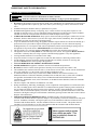
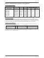
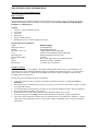
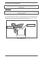
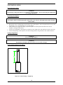
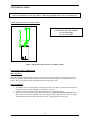
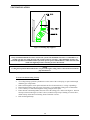
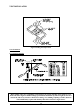
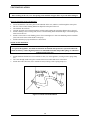
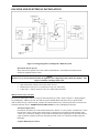
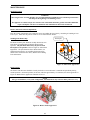
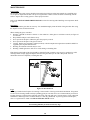
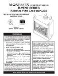
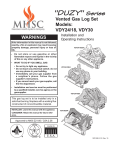
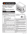
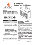
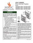
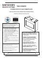
7000 SERIES SUPER B-VENT GAS FIREPLACE INSTALLATION AND OPERATING INSTRUCTIONS MODELS: 724BV(4536,5142)(N,P)(V,E)B WARNING: If the information in these instructions are not followed exactly, a fire or explosion may result causing property damage, personal injury or death. ⎯ Do not store or use gasoline or other flammable vapors and liquids in the vicinity of this or any other appliance. ⎯ WHAT TO DO IF YOU SMELL GAS • • Do not try to light any appliance. Do not touch any electrical switch; do not use any phone in your building; • Immediately call your gas supplier from a neighbor’s phone. Follow the gas supplier’s instructions. • If you cannot reach your gas supplier, call the fire department. ⎯ Installation and service must be performed by a qualified installer, service agency or the gas supplier. This appliance may be installed in an aftermarket, permanently located, manufactured home or mobile home, where not prohibited by local codes. This appliance is only for use with the type of gas indicated on the rating plate. This appliance is not convertible for use with other gases, unless a certified kit is used. For Residential Use-Meets All HUD Requirements For Manufactured Housing Installations DUE TO HIGH TEMPERATURES, THE APPLIANCE SHOULD BE LOCATED OUT OF TRAFFIC AND AWAY FROM FURNITURE AND DRAPERIES. CHILDREN AND ADULTS SHOULD BE ALERTED TO THE HAZARDS OF HIGH SURFACE TEMPERATURE AND SHOULD STAY AWAY TO AVOID BURNS OR CLOTHING IGNITION. YOUNG CHILDERN SHOULD BE SUPERVISED WHEN THEY ARE IN THE SAME ROOM AS THE APPLIANCE. CLOTHING OR OTHER FLAMMABLE MATERIAL SHOULD NOT BE PLACED ON OR NEAR THE APPLIANCE. KEEP THE ROOM AREA CLEAR AND FREE FROM COMBUSTIBLE MATERIALS, GASOLINE, AND OTHER FLAMMABLE VAPORS AND LIQUIDS. • READ BEFORE INSTALLING OR OPERATING AND SAVE THESE INSTRUCTIONS • TABLE OF CONTENTS IMPORTANT SAFETY INFORMATION:..............................................................................................................2 PRODUCT SPECIFICATIONS: ...............................................................................................................................3 HIGH ALTITUDE INSTALLATIONS ...............................................................................................................................3 LISTING & CODE APPROVAL: .............................................................................................................................3 PRE-INSTALLATION INFORMATION: ...............................................................................................................4 BEFORE YOU START:..................................................................................................................................................4 FIREPLACE LOCATION: ...............................................................................................................................................4 WALL AND CEILING CLEARANCE REQUIREMENTS: ....................................................................................................7 COMBUSTIBLE CLEARANCES:.....................................................................................................................................7 MANTEL CLEARANCES:..............................................................................................................................................8 FLOOR CLEARANCES:.................................................................................................................................................8 FINISHING MATERIAL:................................................................................................................................................9 VENT INSTALLATION: .........................................................................................................................................10 POSITIONING THE FIREPLACE:..................................................................................................................................10 VENTING CONFIGURATION:......................................................................................................................................10 INSTALLING VENT COMPONENTS...................................................................................................................11 BEFORE YOU START:................................................................................................................................................11 PIPING INSTALLATIONS: ...........................................................................................................................................11 VENT TERMINATION:................................................................................................................................................13 OUTSIDE AIR KIT INSTALLATION: ............................................................................................................................14 GAS LINE AND ELECTRICAL .............................................................................................................................15 GAS LINE INSTALLATION: ........................................................................................................................................15 ELECTRICAL WIRING:...............................................................................................................................................16 FINAL INSTALLATION .........................................................................................................................................20 WALL FINISHING:.....................................................................................................................................................20 FINISHING THE FIREPLACE FLUSH WITH A WALL:......................................................................................................20 ROCK WOOL PLACEMENT: .......................................................................................................................................20 LAVA ROCK PLACEMENT: ........................................................................................................................................20 LOG PLACEMENT:.....................................................................................................................................................21 GLASS BI-FOLD DOOR INSTALLATION: ....................................................................................................................21 OPERATING INSTRUCTIONS..............................................................................................................................24 BEFORE LIGHTING THE FIREPLACE:..........................................................................................................................25 LIGHTING THE FIREPLACE: .......................................................................................................................................25 MAINTENANCE.......................................................................................................................................................27 BURNER, PILOT AND CONTROL COMPARTMENT:......................................................................................................27 PILOT FLAME: ..........................................................................................................................................................27 BURNER FLAME: ......................................................................................................................................................27 VENT SYSTEM: .........................................................................................................................................................28 OPTIONAL GLASS DOOR:..........................................................................................................................................28 LOGS ........................................................................................................................................................................28 PARTS LIST / ILLUSTRATION ............................................................................................................................29 TROUBLESHOOTING............................................................................................................................................31 1 IMPORTANT SAFETY INFORMATION IMPORTANT SAFETY INFORMATION: INSTALLER: Please leave these instructions with the owner. OWNER: Please read and retains these instructions for future reference. IMPORTANT: Read these instructions carefully before installing or trying to operate this appliance. • • • • • • • • • • • • • • • • • • DO NOT use this appliance if any part has been under water. Immediately call a qualified service technician to inspect the appliance and to replace any part of the control system and any gas control, which has been under water. Installation and repair should be done by a qualified service person. Do NOT install appliance directly on carpeting, vinyl, or other soft floor covering. If the fireplace is to be installed on carpeting or tile, or on any combustible material other than wood flooring, the fireplace should be installed on a metal or wood panel that extends the full width and depth of the fireplace. CARBON MONOXIDE POISONING: Early signs of carbon monoxide poisoning are similar to the flu with headaches, dizziness and/or nausea. If you have these signs, obtain fresh air immediately. Have the appliance and chimney serviced, as it may not be operating properly. To prevent malfunction and/or sooting, this appliance should be inspected before use and at least annually by a professional service person. More frequent cleaning may be required due to excessive lint from carpeting, bedding materials, etc. It is imperative that control compartments, burners and circulating air passageways of the appliance be kept clean. Refer to MAINTENANCE section found in this manual. This gas fireplace is a vented gas appliance. DO NOT burn wood or other material in this appliance. This appliance and vent assembly MUST be vented directly to the outside. This appliance MUST NEVER be connected to a chimney flue(s) servicing a separate solid-fuel burning appliance or any other appliances. Venting terminals shall not be recessed into wall or siding. Inspect the external vent cap on a regular basis to make sure that no debris is interfering with the airflow. Provide adequate clearances around air openings and adequate accessibility clearance for servicing and operation. NEVER obstruct front opening of the appliance. ALWAYS BURN PROPANE MODELS WITH DOORS CLOSED. NEVER OPERATE this appliance without the outside air kit installed and operational. DO NOT use abrasive cleaners on the glass door assembly. Do not clean glass door when it is hot. The installation must conform with local codes or, in the absence of local codes, with the current National Fuel Gas Code, ANSI Z223.1, or the current CAN/CGA B149, Installation Codes. A manufactured home (USA Only) or mobile home OEM installation must conform with the (U.S.) Manufactured Home Construction and Safety Standard, Title 24 CFR, Part 3280, or, when such a standard is not applicable, the Standard for Fire Safety Criteria for Manufactured Home Installation Sites and Communities, ANSI/NFPA 501A, in the United States, or the Mobile Homes Standard, CAN/CSA-Z240 MH Series, in Canada. This unit complies with ANSI Z21.50-2000•CSA 2.22-2000 During manufacturing, fabricating, and shipping, various components of this appliance are treated with certain oils, film, or bonding agents. These chemicals are not harmful but may produce annoying smoke and smells as they are burned off during the initial operation of the appliance; possibly causing headaches or eye and lung irritation. This is a normal and temporary occurrence. The initial break-in operation should last 2-3 hours with the burner at the highest setting. Provide maximum ventilation by opening windows and doors to allow odors to dissipate with continued use. FOR MASSACHUSETTS RESIDENTS ONLY: Installation of this vented gas fireplace in the Commonwealth of Massachusetts requires the damper to be permanently removed or welded into the fully open position. In addition, a naturally vented gas fireplace may not be installed in a bedroom or bathroom in the Commonwealth of Massachusetts. Flex line installation must not exceed 36 inches. This product must be installed by a licensed plumber or gas fitter when installed within the Commonwealth of Massachusetts. 2 PRODUCT SPECIFICATIONS/LISTING & CODE APPROVAL PRODUCT SPECIFICATIONS: Gas Pressure (Inches W.C.) Models Number 724BV4536NV 724BV4536PV 724BV5142NV 724BV5142PV 724BV4536NE 724BV4536PE 724BV5142NE 724BV5142PE Gas Type Natural Gas Propane/LPG Natural Gas Propane/LPG Natural Gas Propane/LPG Natural Gas Propane/LPG Control Type Max Btu Milli-volt Milli-volt Milli-volt Milli-volt Electronic Electronic Electronic Electronic 50000 50000 50000 50000 50000 50000 50000 50000 Max Min Manifold 10.5 13.0 10.5 13.0 10.5 13.0 10.5 13.0 4.0 11.0 4.0 11.0 4.0 11.0 4.0 11.0 3.5 10.0 3.5 10.0 3.5 10.0 3.5 10.0 High Altitude Installations Gas rate shown above is for altitudes up to 2000 ft. When installing this fireplace at an elevation above 2000 ft, it may be necessary to decrease the input rating by changing the existing burner orifice to a smaller size. Input should be reduced four percent (4%) for each 1000 ft above sea level, unless the heating value of the gas has been reduced. Consult your local dealer or gas authority for assistance in determining the proper orifice at your location. LISTING & CODE APPROVAL: The above models have been tested and certified by the applicable laboratories to the standards listed below. MODEL 724BV4536 Series 724BV5142 Series LAB. TYPE CERTIFICATION STANDARD CSA Decorative Vented Gas Fireplace ANSI Z21.50-2000•CSA 2.22-2000 CSA Decorative Vented Gas Fireplace ANSI Z21.50-2000•CSA 2.22-2000 This appliance is only for use with the type of gas indicated on the rating plate. This appliance is convertible for use with other gases, when a certified kit is used. 3 PRE-INSTALLATION INFORMATION PRE-INSTALLATION INFORMATION: Before You Start: Read this homeowner manual thoroughly and follow all instructions carefully. Inspect all contents for shipping damage and immediately inform your dealer if any damage is found. Do not install any unit with damaged, incomplete, or substitute parts. Contents: • Fireplace – Firebox and Burner system • Set of Logs • Lava Rock • Rock Wool • Exterior outside air hood • Bifold glass doors in a separate package (LPG only). Items Required For Installations: Tools: Phillips Screwdriver Hammer Saw and / or saber saw Level Measuring Tape Electric Drill and Bits Plier’s Square Pipe Wrench Building Supplies: Framing Materials Wall Finishing Materials Caulking Material (Noncombustible) Fireplace Surround Material (Noncombustible) Piping Complying with Local Codes Tee Joint Pipe Sealant Approved for use with Propane/LPG (Resistant to Sulfur Compounds) 4” Flexible liner or equivalent Fireplace Location: Plan for the installation of your appliance. This includes determining where the unit is to be installed, the vent configuration to be used, framing and finishing details, and whether any optional accessories (i.e. wall switch, or remote control) are desired. Consult your local building code agency to ensure compliance with local codes, including permits and inspections. The following factors should be taken into consideration: • • • • • • • Clearance to sidewall, ceiling, woodwork, and windows. Minimum clearances to combustibles must be maintained. This fireplace may be installed along a wall, across a corner, or use an exterior chase. Refer to Figure 2 on page 6 for suggested locations. Location should be out of high traffic areas and away from furniture and draperies due to heat from appliance. Never obstruct the front opening of the fireplace. Do not install in the vicinity where gasoline or other flammable liquids may be stored. Vent pipe routing. Refer to Venting section found in this manual for allowable venting configurations. These units can be installed in a bedroom. Refer to National Fuel Gas Code ANSI Z233.1/NFPA 54 - (current edition), the Uniform Mechanical Code - (current edition), and Local Building Codes for specific installation requirements. 4 PRE-INSTALLATION INFORMATION Figure 1: Fireplace Dimensions 5 PRE-INSTALLATION INFORMATION Figure 2: Fireplace Locations and Minimum Clearances Requirements CAUTION: Measure fireplace dimensions and verify framing methods & wall covering details before framing construction begins. 6 PRE-INSTALLATION INFORMATION Figure 3: Wall & Ceiling Minimum Clearances Wall and Ceiling Clearance Requirements: Ensure that minimum clearances shown in Figure 3 are maintained. Left and right clearances are determined when facing the front of the appliance. Follow these instructions carefully to ensure safe installation. Failure to follow these requirements may create a fire hazard. Sidewall Clearance: The clearance from the front edge of the appliance to any combustible wall should not be less than 4” on both the left and right side. Ceiling Clearance: The ceiling must be at least 25” from the top of the front of the fireplace (66” from the bottom of the appliance). Refer to Figure 3. Back-wall Clearance: The appliance may be placed against a combustible back wall. NOTE: There are 1/4” ribs/spacers on the outer shell of the unit to maintain minimum clearance of the outer shell to combustibles. Combustible Clearances: The appliance is a zero clearance fireplace with ribs/spacers defining the minimum space to the sheet metal outer shell. Combustibles may be placed up against these spacers. Do NOT place combustibles (i.e., insulation, wood, etc.) closer than allowed by the spacers or a fire hazard may exist. The ribs/spacers for the sides and rear of the appliance are 1/4” and the top spacers are 3 1/8”. On the front top edge in front of the top framing spacers, a combustible wall (or drywall) may be brought up to the front top and side edges of the unit. Do not over lap the black painted face with combustible materials. Refer to Figure 4. 7 PRE-INSTALLATION INFORMATION Mantel Clearances: If a combustible mantel is installed, it must meet the clearance requirements detailed in Figure 4. Figure 4: Mantel Clearance Floor Clearances: The fireplace may be installed on a flat, hard combustible surface (i.e. flat wood, plywood, or particleboard). Be sure that the fireplace rests on a solid continuous floor or platform with appropriate framing support. Do NOT install appliance directly on carpeting, vinyl, or other soft floor covering. If the fireplace is to be installed on carpeting or tile, or on any combustible material other than wood flooring, the fireplace should be installed on a metal or wood panel that extends the full width and depth of the fireplace. 8 PRE-INSTALLATION INFORMATION CAUTION Measure fireplace dimensions and verify framing methods & wall covering details before framing construction begins. Finishing Material: NOTE Any remote wiring (i.e. remote control, wall switch or 120 volt wiring) must be done prior to final finishing to avoid costly reconstruction. Only noncombustible materials (i.e. brick, tile, slate, steel, or other materials with a UL fire rating of Zero) may be used to cover the black surface of the appliance. A 300°F minimum adhesive may be used to attach facing materials to the black surface. If joints between the finished wall and the fireplace surround are sealed, a 300° F minimum sealant material (General Electric RTV103 or equivalent) must be used. Refer to Figure 7. Combustible Material Noncombustible materials only are permitted to cover black face of unit High temperature sealant permitted at these joints Figure 5: Finishing Material 9 VENT INSTALLATION VENT INSTALLATION: WARNING The following venting instructions are provided as a general guideline. Always check with pipe manufacturer for venting requirements. Positioning The Fireplace: NOTE The fireplace must be installed giving full consideration to the clearance and height requirements identified in this manual. 1. 2. 3. 4. Bend out the four (4) nailing flanges located on the sides of the fireplace. For 5/8” drywall use the two (2) outer most flanges. For ½” drywall use the two (2) inner flanges. Slide the firebox into prepared framing or position fireplace in its final position and frame later. Be sure fireplace is resting on a flat surface. Set unit level and plumb by checking the top and front of unit. Shim side-to-side and front-to-back as necessary. Anchor nailing flanges of the fireplace to the side-framing members using 8d nails or other suitable fasteners. Venting Configuration: WARNING Never use 90 degree elbows WARNING This natural vent fireplace has been tested to use 8” Class B-Vent pipe Vertical Venting Straight up (No Elbow): Figure 6: Vertical Venting – Straight Up 10 VENT INSTALLATION WARNING Never use more than two (2) 45 degree elbows. When using adjustable elbows, never exceed 45 degrees. Vertical Venting with Two (2) 45 Degree Elbow: NOTE V1 and V2 must satisfy this condition: V1 + V2 < 40 feet Max. V1 + V2 > 14 feet Min. Figure 7: Horizontal Venting with Two (2) 45 Degree Elbow INSTALLING VENT COMPONENTS Before You Start: Plan your installation. Set unit in place and survey how best to vent the unit. Select the appropriate pipe for the installation. Read this manual and the manual with the termination cap thoroughly before installing unit or vent system. After vent configuration has been decided, begin attaching pipe to unit. Piping Installations: 1. 2. 3. Attached the first piece piping (elbow or straight pipe) to the pipe connector located above the fireplace. (Secure first section of pipe to damper colar with three (3) Srews). Continue to add vent components. Be certain that each section is locked properly. Where necessary add support brackets. Refer to the Figure 8. Incline runs must be supported every 3 feet. Vertical runs must be supported every 8 feet, using wall straps. Slip wall straps loosely on to pipe. Attach straps to framing members using nails or screws. Tighten nut/bolt to secure pipe. 11 VENT INSTALLATION Figure 8: Installing Pipe Supports WARNING Always maintain minimum clearances around vent systems. The minimum clearances to combustibles is 1” around vent pipe. For ceiling firestops and vertical sections of vent pipe a 1-inch minimum clearance all around the pipe must be maintained. Do not pack the open air spaces with insulation or other materials. This could cause high temperatures and may present a fire hazard. NOTE A ceiling firestop MUST BE installed if the vent passes through a ceiling. Refer to the instructions from the pipe manufacturer. To Locate and Install Ceiling Firestop • • • • • • For ceiling firestops, position a plumb bob over the center of the vertical pipe; to spot a hole through which the pipe will penetrate. Drill a hole through this center point and check the floor for obstructions (i.e. wiring or plumbing). Reposition the fireplace and vent system, if necessary, to accommodate ceiling joists or obstructions. Cut a 11-inch by 11-inch hole through the ceiling, using the center point. Frame the hole with framing lumber the same size as the ceiling joists. Refer to the Figure 9. Position firestop as shown in the Figure 9. If attic is above, mount firestop on top of framing. If room is above, mount firestop on the bottom of framing. Secure with nails or screws. Run vent through firestop. 12 VENT INSTALLATION Figure 9: Ceiling Firestop Location Vent Termination: For Vertical Termination ` Figure 10: Minimum Vent Height for Various Roof Pitches WARNING Major building codes specify a minimum vent height above the rooftop depending on the pitch of the roof. Refer to the above figure for minimum heights, provided the termination cap is at least eight (8) feet from a vertical wall, and two (2) feet below a horizontal overhang. Trees, buildings, adjoining roof lines, & adverse wind conditions may require taller chimneys than what is shown in the figure below. 13 VENT INSTALLATION NOTE When working on the roof, cover the opening of the installed vent pipes below to prevent debris falling in. To Locate and install Vertical Termination • • • • • Locate and mark the vent center point on the underside of the roof, and drive a nail through the center point. The size of the roof hole framing dimensions depends on the pitch of the roof Cut and frame the roof hole. Continue to install vent sections through the roof hole until reaching the appropriate distance above the roof. Attach a flashing to the roof using nails, and use a non-hardening mastic around the edges of the flashing base when it meets the roof. Attach a storm collar over the flashing joint to form a watertight seal. Place non-hardening mastic around the joint, between the storm collar and the vertical pipe. Attach termination per pipe manufacturer’s instructions. • • Outside Air Kit Installation: Warning To operate this appliance, the outside air kit MUST be installed and operational. Operation without the outside air kit may result in high temperature on combustible materials and possible spillage of combustion product into the living area. 1. 2. 3. Attach aluminum flexible hose (#2) to outside air door (#1) on the appliance, securing it with a spring clamp (#3). Cut a hole through outside wall, place outside air hood (#4) in hole and secure with sealant. Attach other end of flex hose (#2) to outside air hood, securing it with a spring clamp (#3). Figure 11: Outside Air Kit Installation 14 GAS LINE AND ELECTRICAL INSTALLATION GAS LINE AND ELECTRICAL Gas Line Installation: NOTE Plumbing connections should only be performed by a qualified, licensed plumber. Main gas supply must be off when plumbing gas line to fireplace or performing service. • • • • • • • Consult all codes. All gas piping must be installed to comply with local codes, or in the absence of local codes, with the latest edition of the National Fuel Gas Code ANSI Z223.1. The appliance and its appliance main gas valve must be disconnected from the gas supply piping system during any pressure testing of that system at test pressure in excess of 1/2 psi (3.5 kPa). The appliance must be isolated from the gas supply piping system by closing the equipment shutoff valve during any pressure testing of the gas supply piping system at test pressures equal to or less than 1/2 psi (3.5 kPa). Use new black iron or steel pipe. Internally tinned copper or copper tubing can be used per National Fuel Gas Code, section 2.6.3, providing gas meets sulfide limits, and where permitted by local codes. An ANSI approved manual shutoff valve must be installed immediately upstream of the gas supply connection to the fireplace A sediment trap may be installed upstream of the fireplace to prevent moisture and contaminants from passing through to the fireplace control and burner. Failure to do so could prevent appliance from operating reliably. On some local codes, the gas line must be connected to a gas shut-off valve recessed flush into the wall or floor outside the fireplace. The valve should be controlled by a removable valve key for safety. In this case, remove factory shut-off valve from the flex line and connect line direct to stub. WARNING Support the shut-off valve when attaching 1/2” gas line. Use a wrench to hold shut-off valve stationary. Do not twist the flex line when tightening the 1/2” gas line. WARNING Connecting directly to an unregulated propane/L.P.G. tank can cause an explosion. An external regulator must be used on all propane/LPG appliances to reduce the supply tank pressure to 13” w.c. (maximum). WARNING Do not connect directly to natural gas 1/2- psi or 2-psi systems. Always make sure the natural gas pressure is regulated to 10.5 w.c. (maximum) before operating the unit. • • • • • Check gas type. The gas supply must be the same as stated on the appliance’s rating decal. If the gas supply is different from the fireplace, STOP! Do not install the appliance. Contact your dealer immediately. To ease installation, a 30” flex line with manual shut-off valve has been installed on this fireplace. Install 1/2” gas line onto shut-off valve. Locate the gas line access hole in the outer casing of the fireplace. Remove the screw on the gas line cover plate. Open the fireplace door, insert the gas supply line through the knock out hole on the gas line cover plate, and connect it to the shut-off valve. After completing gas line connection, purge air from gas line and test all gas joints from the gas meter to the fireplace for leaks. Use a soap and water solution or a gas sniffer. To check gas pressure at valve, turn captured screw counter clockwise 2 or 3 turns and then place tubing to pressure gauge over test point. Refer to Figure 12: Gas Pressure Check at Gas Valve. After taking pressure reading, be sure and turn captured screw clockwise firmly to re-seal. Do not over torque. Check for gas leaks. WARNING Do not use open flame to check for gas leaks. 15 GAS LINE AND ELECTRICAL INSTALLATION Figure 12: Gas Pressure Check at Gas Valve Electrical Wiring: Standing Pilot Ignition Wiring-Millivolt Control: WARNING Do not connect 110-120 VAC to the Remote Wall Switch, DC Remote Control or the Millivolt Control Valve. The appliance will malfunction or the valve will be damaged. CAUTION Electrical connections should only be performed by a qualified, licensed electrician. Main power must be off when connecting to main electrical power supply or performing service. All wiring shall be in compliance with all local, city, and state codes. The appliance, when installed, must be electrically grounded in accordance with local codes, or in the absence of local codes, with the National Electrical Code ANSI / NFPA 70 (latest edition), or the Canadian Electrical Code, CSA C22.1. Label all wires prior to disconnection when servicing controls. Wiring errors can cause improper and dangerous operations. Verify proper operation after servicing. Remote Wall Switch Fifteen (15) feet of 18 Ga. wire is provided as standard with this fireplace, that may be routed to a remote wall switch. The wire has been pre-wired at the valve and routed through the right side, outer shell. (Access is also available on the left side through the square hole on that side). Position the wall switch inside of a non-metallic junction box (not provided) at the desired location on the wall. Refer to Figure 13: Wiring Diagram for Standing Pilot - Millivolt System. Do not extend beyond the wall switch wire length provided. NOTE Extended lengths of wire may cause the fireplace not to function properly. Longer length of wire is permitted if the wire is a larger gauge (diameter) wire. Always check with local codes. 16 GAS LINE AND ELECTRICAL INSTALLATION Figure 13: Wiring Diagram for Standing Pilot - Millivolt System Optional DC Remote Systems These instructions supersede the section entitled “Hearth Mount” in the Millivolt hand held remote instructions supplied with the remote. NOTE Remote receiver must be mounted outside the appliance, due to high temperatures inside the chamber. This will prevent failures and longer battery life. 1. 2. 3. Plug in the remote connector wire to the remote receiver. Mount remote control receiver at junction box (for your wall switch) Connect the ¼” female connector to the valve TPTH and TH terminal. Millivolt Control Valve Checklist: The millivolt (thermopile) control is a self-powered combustion gas control. Refer to Figure 13: Wiring Diagram for Standing Pilot - Millivolt System. The millivolt system and individual components may be checked with a millivolt meter having 1-1000 mV range. Conduct each check listed below by connecting the meter test leads to the terminals indicated. Refer to OPERATING INSTRUCTIONS for safety and lighting instructions. Thermopile Output Check Pilot must be lit and the valve control knob turned to the “PILOT” or “ON” position. “RS-ON-OFF” switch must be in the “OFF” position. Meter leads must be connected to the TP and the TH/TP terminals on the control valve. If the meter reading is not 500-millivolt minimum, then readjust pilot for maximum millivolt output. If millivolt reading is still below minimum specified, check wire connection and then replace the thermopile. Complete Millivolt System Check 17 GAS LINE AND ELECTRICAL INSTALLATION Pilot must be lit and the valve control knob turned to the “ON” position. Meter leads must be connected to the TP and the TH/TP terminals on the control valve. • Turn RS-ON-OFF switch to the “ON” position. 9 If meter is reading more than 175 millivolt and the main burner does not come on, then replace control valve. 9 If meter is reading less than 175 millivolt, then refer to TROUBLESHOOTING section of this manual to determine the cause of the low reading. • Turn RS-ON-OFF switch to the “RS ” position and wall switch to “ON” 9 If meter is reading more than 175 millivolt and the main burner does not come on, then replace control valve. 9 If meter is reading less than 175 millivolt, then refer to TROUBLESHOOTING section of this manual to determine the cause of the low reading. Electronic Pilot Ignition Wiring: WARNING Do not connect 110-120 VAC to the Remote Wall Switch. The appliance will malfunction or be destroyed. Figure 14: Wiring Diagram for Electronic Ignition System Remote Wall Switch Position the wall switch. Refer to Figure 14: Wiring Diagram for Electronic Ignition System. Do not extend beyond the 15 feet of wire. 18 GAS LINE AND ELECTRICAL INSTALLATION Optional DC Remote Systems These instructions supersede the section entitled “Hearth Mount” in the Millivolt hand held remote instructions supplied with the remote. NOTE Remote receiver must be mounted outside the appliance, due to high temperatures inside the chamber. This will prevent failures and longer battery life. 1. 2. 3. Plug in the remote connector wire to the remote receiver. Connect the wire terminal from the remote receiver to replace the 15’ wall switch connection to the switch as shown in the Figure 14. Mount remote control receiver at junction box (for your wall switch). 19 FINAL INSTALLATION FINAL INSTALLATION Wall Finishing: Definitions: Combustible Materials - Materials made of or surfaced with wood, compressed paper, plant fibers, or other materials that are capable of being ignited and burned. Such materials are considered combustible even though flameproof, fire retardant, treated, or plastered. Non-Combustible Materials - Materials which will not ignite and burn. Such materials are those consisting entirely of steel, iron brick, tile, concrete, slate, glass, marble, or combination thereof, or have a UL Fire rating of Zero (0). High Temperature Sealant Material - Sealant that will withstand high temperature; General Electric RTV103 or equivalent. Finishing the fireplace flush with a wall: When finishing the face of the fireplace, combustible material may be brought up to the side or top edge of the fireplace, but must never overlap the black metal face. The black metal face may be covered with non-combustible material only. After applying the finishing material, a non-combustible sealant, 1/8” minimum, should be used to close off any gaps at the top and sides between the fireplace and the finishing to prevent cold air leaks. Refer to Figure 5: Finishing Material section in this manual for allowable locations for combustible materials. Rock Wool Placement: Rock wool should be evenly covering the burner from front to back. The rock wool should be separated into chunks about the size of a nickel. The bag supplied has an excess of rock wool. The remaining may be used as filler over time. Lava Rock Placement: Sprinkle a thin layer of lava rock on the floor of the inner chamber. DO NOT pile up in any area. It should be placed in a single layer only around but not on any portion of the burner. WARNING Do not sprinkle the lava rock on top of the burner. This may cause potential sooting, glass breakage and/or a fire hazard 20 FINAL INSTALLATION Log Placement for fiber VDY24/18D3R: Step 1: Line up pins on bottom of Rear Log #1 with pins on grate bar and place on grate. Step 2: Place Front Left Log #2 on left front of grate bar lining up cutout in bottom of log with grate bar. Step 3: Place Front Right Log #3 on right front of grate bar lining up cutout in bottom of log with grate bar. Make sure Log #3 touches Log #1. Step 4: Place back end Top Middle Log #4 on Log #1. Press the side of Log #4 up against raised area of Log #1. Line up notch in front end of #4 with grate bar. Step 5: Rest Top Right Log #5 on Log #3. Step 6: Line up Top Left Log #6 with notches on Log #2 and Log #4 Figure 19: Log Placement 21 FINAL INSTALLATION Glass Bi-Fold Door Installation: WARNING Glass doors must be installed on all Propane/LPG units and operated in the closed position to eliminate any potential for soot spillage into the room. When installing a natural gas unit with glass door option, the unit must be operated with glass doors completely opened or completely closed. 1. 2. 3. 4. Remove and discard the two (2) screws that secure the C-Channel below the top opening of the fireplace. Attach bottom rail (#1) to unit with 2 sheet metal screws (#3). Refer to Figure 20. Attach top rail (#2) to unit with 2 sheet metal screws (#3). Refer to Figure 20. Place bottom metal door pin in bottom spring latch then rotate top of door into top spring latch. Refer to Figure 21. Repeat step 3 for other door. Figure 20: Door Rail Installation Figure 21: Glass Door Installation NOTE Follow installation instructions located inside package. 22 FINAL INSTALLATION Damper operation: NOTE For Massachusetts residents only: Installation of this vented gas fireplace in the Commonwealth of Massachusetts requires the damper to be permanently removed or welded into the fully open position. In addition, a naturally vented gas fireplace may not be installed in a bedroom or bathroom in the Commonwealth of Massachusetts. 1. 2. 3. When damper arm (1) is all the way to the left and locked into position, the damper system is closed. (Refer to Figure 22.) Pull damper arm (1) forward and unlock from closed position by swinging damper arm (1) to the right. (Refer to Figure 22.) Swing damper arm (1) to the right, forcing into the locked position, to open damper system. (Refer to Figure 22.) WARNING Damper must be in open position when appliance main burner is operating. The damper system must be LOCKED into the OPEN position during operation. If damper is not open the appliance will shut down at the pilot. See lighting instructions if this occurs. If damper system is not locked into the open position, the appliance my cause some spillage into the living area before the temperature switch can shut the pilot off. Do not install a damper device to the appliance. Only use damper device that comes with the unit NOTE Remove damper instruction tag before operating the unit Figure 22: Damper Operation Hi Temperature Cut Off Disc: This unit is equipped with a shut off disc that helps prevent spillage due to a down draft. It also helps prevent operation of the unit with damper closed. The Hi Temp. switch is located on the upper left corner of the fireplace opening. DO NOT OPERATE THE FIREPLACE WITH THE SWITCH BYPASSED 23 OPERATING INSTRUCTIONS Before Lighting the Fireplace: • Read the IMPORTANT SAFETY INFORMATION section at the beginning of this homeowner manual. • Before lighting, check the fireplace for possible gas leaks. • Before lighting, check for possible obstructions that could be blocking the vent termination or the front louver. • Any component that is found to be faulty must be replaced with an approved component. Tampering with the fireplace components is dangerous and voids all warranties. • A small amount of air may be present in the gas line. It will take a few minutes for the lines to purge. Once the purging is complete, the fireplace will light and will operate normally. • During the initial purging, never allow the gas valve control knob to remain depressed in the pilot position without pushing the ignitor button once every second. • Subsequent lighting of the fireplace will not require this purging of air from the gas lines, unless the gas valve has been shut-off for a long period. Lighting the Fireplace: You may notice the following: • • • • A slight odor. During manufacturing, fabricating, and shipping, various components of this fireplace are treated with certain oils, film, or bonding agents. These chemicals are not harmful but may produce annoying smoke and smells as they are burned off during the initial operation of the fireplace. Operate the appliance 2 to 3 hours at the highest setting to burn off all the oils, films, etc. Fogging on Bi-Fold Door glass. For the first few minutes, after each lighting, vapor may condense and fog the glass. This condensation will disappear in a few minutes. Noise from the fireplace. This is due to metal expanding and contracting as it heats up and cools down, similar to the sound produced by a furnace or heating duct. Flame appearance. It will take about 15 to 30 minutes for the flames to turn yellow and some portions of the logs to glow. 24 OPERATING INSTRUCTIONS LIGHTING INSTRUCTIONS MILLIVOLT CONTROL 1. STOP! Read the safety information below on this label. Open access door on left side of floor to reveal gas valve, then locate RS-OFF-ON rocker switch on left side inner chamber. Turn RS-OFF-ON rocker switch to “OFF”. Turn remote switch to “OFF” Push in gas valve knob and turn clockwise to “OFF” Wait five (5) minutes to clear out any gas. Than smell for gas, including near the floor. If you smell gas, STOP! Follow “B” in the safety information below on this label. If you don’t smell gas, go to the next step. Find Pilot-located under the log. Turn gas valve counterclockwise to “Pilot” 2. 3. 4. 5. 6. 7. 8. With the control knob pushed in, push in and release the piezo ignitor button to light the pilot. 9. Continue pushing the control knob in for a further 60 seconds to prevent the flame detector from shutting off the gas while the probe is warming up. Release the control knob. 10. •If the pilot will not stay lit after several tries, turn the gas control knob clockwise to “OFF” and call your service technician or gas supplier. •If the knob does not pop out when released, stop and call your service technician or gas supplier. 11. Turn knob counterclockwise to “ON” 12. After the pilot has been lit for one minute, the burner can be turned on. Turn RS-OFF-ON switch to “ON” or turn RS-OFF-ON switch to “RS” and remote switch to “ON”. Gas Valve Pilot TO TURN OFF GAS TO APPLIANCE 1. 2. 3. 4. Open left side access door. Turn RS-OFF-ON rocker switch to “OFF”. Push in gas valve knob slightly and turn clockwise to Close access door. “OFF”. FOR YOUR SAFETY READ BEFORE LIGHTING WARNING: If you do not follow these Instructions exactly, a fire or explosion may result causing property damage, personal injury or loss of life. A. This appliance is equipped with an ignition device (piezo) which automatically lights the pilot. When lighting the pilot, follow these instructions exactly. C. Use only your hand to push in or turn the gas control knob. Never use tools. If the knob will not push in or turn by hand, don’t try to repair it, call a qualified service technician. Force or attempted repair may result in a fire or explosion B. BEFORE OPERATING smell all around the appliance area for gas. Be sure to smell next to the floor because some gas is heavier than air and will settle on the floor. WHAT TO DO IF YOU SMELL GAS * Do not try to light any appliance * Do not touch any electric switch; do not use any phone in your building. * Immediately call your gas supplier from a neighbor's phone. Follow the gas supplier’s instructions. * If you cannot reach your gas supplier, call the fire department. 25 D. Do not use this appliance if any part has been under water. Immediately call a qualified service technician to inspect the appliance and to replace any part of the control system and any gas control which has been under water. OPERATING INSTRUCTIONS LIGHTING INSTRUCTIONS ELECTRONIC IGN 1. 2. 3. 4. STOP! Read the safety information below on this label. Set the switch to “OFF” Turn off all electric power to the appliance. This appliance is equipped with an ignition device which automatically lights the burner. Do not try to light the burner by hand. 5. 6. 7. 8. Wait five (5) minutes to clear out any gas. Than smell for gas, including near the floor. If you smell gas, STOP! Follow “B” in the safety information below on this label. If you don’t smell gas, go to the next step. Turn on all electric power to appliance. Turn RS-OFF-ON rocker switch to “ON” If the appliance will not operate, follow the instructions “To turn Off Gas To Appliance” and call you service technician or gas supplier. Electronic Gas Valve TO TURN OFF GAS TO APPLIANCE 1. 2. Turn RS-OFF-ON rocker switch to “OFF”. Turn off all electric power to the appliance if service is to be performed FOR YOUR SAFETY READ BEFORE LIGHTING WARNING: If you do not follow these Instructions exactly, a fire or explosion may result causing property damage, personal injury or loss of life. 26 MAINTENANCE MAINTENANCE WARNING Turn off gas before servicing fireplace. It is recommended that a qualified service technician perform these check-ups at the beginning of each heating season. The appliance area must be kept clear and free from combustible materials, gasoline and other flammable vapors and liquids. The flow of combustion and ventilation air must not be obstructed. Burner, Pilot and Control Compartment: Keep the control compartment, logs, and burner areas surrounding the logs clean by vacuuming or brushing at least twice a year. Make sure the pilot air intake is free of obstructions at all time. Thermopile Standing-Pilot Flame Only: The flames from the pilot should be visually checked as soon as the heater is installed and periodically during normal operation. The pilot flame must always be present when the fireplace is in operation. Refer to Figure 23: Pilot Flame Appearance. The pilot flame has three distinct flames, one engulfing the thermopile, one engulfing the thermocouple (which is not connected to the valve), and the other reaching to the main burner. Figure 23: Pilot Flame Appearance Burner Flame: The flames from the burner should be visually checked as soon as the heater is installed and periodically during normal operation. In normal operation, at full rate, and after approximately 15-30 minutes, the flame appearance in Figure 24: Burner Flame Appearance should be observed. NOTE The type of installation, vent system configuration, and wind effects may cause the flame patterns to vary. Figure 24: Burner Flame Appearance 27 MAINTENANCE Vent System: The fireplace and venting system should be inspected before initial use and at least annually by a qualified field service person. Inspect the external vent cap on a regular basis to make sure that no debris is interfering with the airflow. Inspect entire venting system to ensure proper function. Refer to the VENT/OUTSIDE AIR KIT INSTALL section for removing and reinstalling vent components. Refer to page 14. Glass Door: Periodically clean the glass door as necessary. You should thoroughly clean the inside of the glass door after using the fireplace for the second or third time. When cleaning the glass, remember: • Warning: NEVER use abrasive cleaners or clean when hot. Allow glass to cool before removal (see figure 25 for removal). • Keep children and pets a safe distance away. • Never operate the fireplace without the glass door properly secured. • Never operate the fireplace if the glass is broken. • Caution: Replace any glass that is chipped, cracked, or broken. Replacement glass door assemblies MUST be supplied by the fireplace manufacturer. • Warning: No substitute materials may be used. • Warning: Handle glass door with care to avoid striking or slamming shut Film deposit on the inside of the glass should be cleaned off using a nontoxic, non-corrosive, non-abrasive, mildcleaning solution. Simply apply an adequate amount to the glass and wipe off with a damp cloth. After all maintenance has been completed, re-install glass door. Figure 25: Door Removal Logs: Leave logs installed in the fireplace for cleaning. Vacuum surface of the logs with a brush attachment. If logs must be removed for cleaning, handle carefully by holding gently at each end. Gloves are recommended to prevent skin irritation from logs. If skin becomes irritated, wash gently with soap and water. Vacuum surface of logs with brush attachment or brush logs with a soft bristle brush (i.e. clean, dry paintbrush). To place logs back in the fireplace, refer to “Log Placement” found in the FINAL INSTALLATION section. NOTE Soot cleaning fluid may be used on refractory logs. 28 PARTS LIST / ILLUSTRATIONS PARTS LIST / ILLUSTRATION B VDY24/18D3R Item 1 2 3 4 5 6 Description Rear Log Front Left Log Front Right Log Top Middle Log Top Right Log Top Left Log 4536 32D2118 32D2117 32D2116 32D2114 32D2113 32D2115 5142 32D2118 32D2117 32D2116 32D2114 32D2113 32D2115 Firebox Components: Standard and Accessories Item 1 2 2a 2b 2c 2d 3 4 5 6 7 8 9 Description Hi Temperature limit switch Firebrick walls (weathered) Firebrick center 36” Firebrick left side Firebrick right side Firebrick center 42” Pull Screen Bi-Fold Brass/Black Doors Manual Remote Control Embers Cinders Lava Rock Wall Switch Kit Qty 1 1 1 1 1 1 1 1 1 1 1 1 1 4536 41D0202 FB4536W9 41D2011 41D2009 41D2010 MS BBD4536/BLD4536 RCM/RCB EMBERS CINDERS VR1000A MVWS 29 5142 41D0202 FB5142W9 41D2009 41D2010 41D2012 MS BBD5142/BLD5142 RCM/RCB EMBERS CINDERS VR1000A MVWS PARTS LIST / ILLUSTRATIONS Engine Components: Standing Pilot – Millivolt Control Item Description 1 Gas Valve Assembly 2 Pilot Assembly 3 Burner Tube 4 Flexhose with Shutoff Valve 5 Rocker Switch 6 Piezo Igniter 7 Injector 8 Burner Assembly 9 Wire Assembly 10 Grate Weld Assembly Qty 1 1 1 1 1 1 1 1 1 1 4536NV 26D0506 41D0327 41D0031K 23D6046 41D0048 14D0503 32D0100 41D0500K 41D0201 41D1001K 4536PV 26D0507 41D0328 41D0031K 23D6046 41D0048 14D0503 32D0118 41D0501K 41D0201 41D1001K Conversion Kit (Not Shown) for Millivolt-Control Only 4536 Conversion NG to LPG 1 SNPK3642 4536 Conversion LPG to NG 1 5142 Conversion NG to LPG 1 5142 Conversion LPG to NG 1 SPNK3642 30 5142NV 26D0506 41D0327 41D0031K 23D6046 41D0048 14D0503 32D0100 41D0500K 41D0201 41D1001K 5142PV 26D0507 41D0328 41D0031K 23D6046 41D0048 14D0503 32D0118 41D0501K 41D0201 41D1001K SNPK3642 SPNK3642 Electronic Ignition Control Item Description Qty 1 Gas Valve Assembly 1 2 Pilot Assembly 1 3 Burner Tube 1 4 Flexhose with Shutoff Valve 1 5 Rocker Switch 1 7 Injector 1 8 Burner Assembly 1 9 Wire Assembly 1 14 Ignition Module 1 15 Transformer 1 Conversion Kit (Not Shown) for Electronic Ignition 4536 Conversion NG to LPG 1 4536 Conversion LPG to NG 1 5142 Conversion NG to LPG 1 5142 Conversion LPG to NG 1 31 4536NE 37D0016 54D2004 41D0031K 23D6046 41D0048 32D0100 41D0500K 54D2007 37D0325 37D0027 4536PE 37D0017 54D2005 41D0031K 23D6046 41D0048 32D0118 41D0501K 54D2007 37D0325 37D0027 5142NE 37D0016 54D2004 41D0031K 23D6046 41D0048 32D0100 41D0500K 54D2007 37D0325 37D0027 5142PE 37D0017 54D2005 41D0031K 23D6046 41D0048 32D0118 41D0501K 54D2007 37D0325 37D0027 SNPK3642E SPNK3642E SNPK3642E SPNK3642E TROUBLESHOOTING STANDING PILOT - MILLIVOLT SYMPTOM POSSIBLE CAUSE 1. Spark ignitor will A. Wire disconnected. not light pilot after repeated triggering of piezo. B. Defective ignitor. C. No gas or low gas pressure. 2. 3. Pilot will not stay lit after carefully following lighting instructions. Pilot burning, valve knob turned to “ON”, switch is turned to “ON” or “RS”, but burner will not ignite. D. No Propane/LPG in tank A. Defective Valve A. Defective switch, wall switch, remote control or wire B. Pilot flame too small C. Defective or malfunctioning thermopile D. Defective valve 4. Frequent pilot outage problem. A. Pilot flame may be too high or too low, causing pilot safety to drop out REMEDY Open door and check to make sure wire is connected to ignitor. Check for spark at electrode and pilot. If no spark and electrode wire is properly connected, replace pilot assembly. Check remote/manual shut off valve from fireplace. Low pressure can be caused by bent lines, restricted lines, low pressure line pressure. Consult with plumber or gas supplier. Check Propane/LPG tank. Refill tank If thermopile is producing more than 325 mV, replace faulty valve. Check switch and wire for proper connection. Place jumper wires across terminals of switch. If burner comes on, replace defective switch. If the switch is OK, repeat the same procedure on remote control. If burner comes on, replace remote control. Place jumper wire across wire at gas valves (terminals marked TH and TP/TH). If burner comes on, wires are faulty or connections are bad. Replace wire. If pilot flame is not close enough to the thermopile, adjust pilot flame. Check thermopile wire connections to make sure all are tight and that the thermopile is fully inserted into pilot assembly. Check thermopile with a millivolt meter. Connect leads to TP and TP/TH terminals on the control valve. If meter reading is below 325 mV, replace pilot assembly Turn valve knob to “On” and switch to “ON”. Take a reading at the thermopile leads (TP & TP/TH) on the valve. If the meter reads greater than 100 mV and the burner does not light, replace defective valve Clean and adjust the pilot flame for maximum flame impingement on thermopile. 32 ELECTRONIC IGNITION 33 GENERAL TROUBLESHOOTING: 1. Glass Soots A. Flame impingement on logs Install log set per the instructions Inspect the injector and air intake area. Make sure this area does not have any blockage from debris and clean. 2. 3. 4. 5. Poor draft due to venting Poor draft due to termination cap. Poor draft due to ext. environment. Poor draft due to internal environment. A. Too much offset. Check gas supply Reduce offset and/or raise termination. B. Too many elbows Reduce number of elbows C. Vent height too short Raise vent D. Vent too close to roof line E. Blockage is restricting venting capacity F. Incorrect vent type Raise vent G. Venting has been constructed with too large or too small vent. H. More than one appliance is using one venting system. A. Cap obstructed by a decorative enclosure. B. Cap is crushed, damaged or missing. A. Buildings, trees, roof lines interfering with venting. B. Wind C. Vent exposed to cold chase. D. Vent exposed to cold weather. A. Negative air pressure. Remove blockage Replace with proper B-Vent Replace with proper size Construct a single venting system for each appliance Remove or open enclosure or raise cap above it. Replace cap Maintain proper clearances and heights to external obstructions; Beware of overhangs. Use cap designed for high winds; raise venting height. Insulate chase. Enclose vent within home. To test for negative air pressure, open a window in the room with the fireplace to see if the unit starts drafting correctly. Make sure the damper system is in the open position. 6. Unit shuts down prematurely. A. Blockage or restriction in venting. Check for and remove blockage and light pilot following lighting instructions. B. Damper system closed. Open damper system and light pilot following lighting instructions. If damper system will not operate, call contractor. 34 LIMITED LIFETIME WARRANTY POLICY Lifetime Warranty The following components are warranted for life to the original owner, subject to proof of purchase: Firebox, Combustion Chamber, Heat Exchanger, Grate, Stainless Steel Burners, and Vented Fiber Ceramic and Refractory Logs. Basic Warranty Monessen Hearth Systems (MHS) warrants the components and materials in your gas appliance to be free from manufacturing and material defects for a period of two years from date of installation. After installation, if any of the components manufactured by MHS in the appliance are found to be defective in materials or workmanship, MHS will, at its option, replace or repair the defective components at no charge to the original owner. MHS will also pay for reasonable labor costs incurred in replacing or repairing such components for a period of two years from date of installation. Any products presented for warranty repair must be accompanied by a dated proof of purchase. This Limited Lifetime Warranty will be void if the appliance in not installed by a qualified installer in accordance with the installation instructions. The Limited Lifetime Warranty will also be void if the appliance is not operated and maintained according to the operating instructions supplied with the appliance, and does not extend to (1) firebox/burner assembly damage by accident, neglect, misuse, abuse, alterations, negligence of others, including the installation thereof by unqualified installers, (2) the costs of removal, reinstallation or transportation of defective parts on the appliance, or (3) incidental or consequential damage. All service work must be performed by an authorized service representative. This warranty is expressly in lieu of other warranties, express or implied, including the warranty of merchantability of fitness for purpose and of all other obligations or liabilities. MHS does not assume for it any other obligations or liabilities in connection with sale or use of the appliance. It states that do not allow limitations on how long an implied warranty lasts, or do not allow exclusion of indirect damage, those limitations of exclusions may not apply to you. You may also have additional rights not covered in the Limited Lifetime Warranty. MHS reserves the right to investigate any and all the claims against the Limited Lifetime Warranty and decide upon method of settlement. For information about this warranty, contact: Technical Services Monessen Hearth Systems 149 Cleveland Drive Paris, Kentucky 40361 41D2002 Rev 5 April 2008 35