1
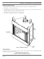
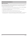
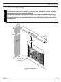
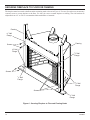
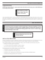
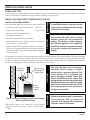
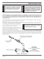
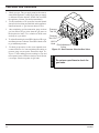
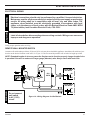
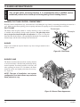
B-VENT SERIES
NATURAL VENT GAS FIREPLACE
INSTALLATION AND OPERATING
INSTRUCTIONS
MODELS:
BBV400 SBV400 SBV500
WARNINGS
IF THE INFORMATION IN THESE INSTRUCTIONS ARE
NOT FOLLOWED EXACTLY, A FIRE OR EXPLOSION
MAY RESULT CAUSING PROPERTY DAMAGE,
PERSONAL INJURY OR LOSS OF LIFE.
–
Do not store or use gasoline or other flammable
vapors and liquids in the vicinity of this or any
other appliance.
–
WHAT TO DO IF YOU SMELL GAS
DUE TO HIGH TEMPERATURES, THE
APPLIANCE SHOULD BE LOCATED
OUT OF TRAFFIC AND AWAY FROM
FURNITURE AND DRAPERIES.
• Do not try to light any appliance.
• Do not touch any electrical switch; do not use
any phone in your building.
• Immediately call your gas supplier from a
neighbor's phone. Follow the gas supplier's
instructions.
• If you cannot reach your gas supplier, call the
fire department.
CHILDREN AND ADULTS SHOULD
BE ALERTED TO THE HAZARDS OF
HIGH SURFACE TEMPERATURE AND
SHOULD STAY AWAY TO AVOID BURNS
OR CLOTHING IGNITION.
Installation and service must be performed
by a qualified installer, service agency or the
gas supplier.
CLOTHING OR OTHER FLAMMABLE
MATERIAL SHOULD NOT BE PLACED ON
OR NEAR THE APPLIANCE.
WARNING: Improper installation, adjustment,
alteration, services or maintenance can cause injury or
property damage. Refer to this manual. For assistance
or additional information consult a qualified installer,
service agency or the gas supplier.
KEEP THE ROOM AREA CLEAR AND
FREE FROM COMBUSTIBLE MATERIALS,
GASOLINE, AND OTHER FLAMMABLE
VAPORS AND LIQUIDS.
–
YOUNG CHILDREN SHOULD BE
SUPERVISED WHEN THEY ARE IN THE
SAME ROOM AS THE APPLIANCE.
READ BEFORE INSTALLING. SAVE THESE INSTRUCTIONS
CONTENTS
Thank you and congratulations on your purchase of a
Monessen Hearth Systems Fireplace.
PLEASE READ THE INSTALLATION AND OPERATION INSTRUCTIONS BEFORE USING THE APPLIANCE!
IMPORTANT: Read all instructions and warnings carefully before starting installation.
Failure to follow these instructions may result in a possible fire hazard and will void the warranty.
Code Approval .................................................. 5
Final Installation ............................................. 23
Rock Wool Placement ................................. 23
Log Placement ............................................ 23
Lava Rock and Ember Placement .............. 23
Pre-Installation Information
Installing Above 2000 Feet ............................ 6
Orifice Sizes, Pressures and BTUs ............... 6
Before You Install .......................................... 6
Fireplace Framing ......................................... 7
Fireplace Dimensions ................................... 8
Fireplace Location ....................................... 10
Operating Instructions ................................... 24
What To Do If You Smell Gas ...................... 24
Lighting Pilot for the First Time ................... 24
Lighting Pilot ............................................... 25
Lighting Burner ............................................ 26
Lighting Electronic IGN ............................... 27
To Turn Off Gas ........................................... 27
Clearances .......................................................11
Cleaning and Maintenance ............................ 28
Burner, Pilot and Control Compartment ...... 28
Pilot Flame .................................................. 28
Burner ......................................................... 28
Burner Flame .............................................. 28
Vent System ................................................ 29
Logs ............................................................ 29
Rock Wool .................................................. 29
Important Safety Information .......................... 3
Product Features .............................................. 5
Securing Fireplace to Floor or Framing ....... 12
Installation Information .................................. 13
Vent Installation .............................................. 13
Installation Precautions ............................... 13
Installation Planning .................................... 14
Outside Combustion Air Precautions and
Recommendations ................................... 16
Combustion Air Assembly ............................. 17
Fireplace Installation ...................................... 18
Check Gas Type.......................................... 18
Installing Gas Piping to Fireplace/Burner
System Location ......................................... 18
Replacement Parts ......................................... 30
Firebox Components ................................... 30
Logs ............................................................ 31
Standing Pilot - Millivolt Control .................. 32
Electronic Ignition ........................................ 33
Troubleshooting ............................................. 34
Warranty ...........................................Back Cover
Checking Gas Pressure ................................. 20
Electrical Installation ..................................... 21
Electrical Wiring .......................................... 21
Remote Wall Mounted Switch ..................... 21
Electronic Pilot Ignition Wiring .................... 22
2
62D4036
IMPORTANT SAFETY INFORMATION
WARNING
INSTALLER
Please leave these instructions with the appliance.
OWNER
Please retain these instructions for future reference.
• Read this owner’s manual carefully and completely before trying to assemble, operate,
or service this fireplace.
• Any change to this fireplace or its controls can be dangerous.
• Improper installation or use of this fireplace can cause serious injury or death from
fire, burns, explosions, electrical shock and carbon monoxide poisoning.
This fireplace is a decorative gas appliance. This fireplace
must be properly installed by a qualified service person.
CARBON MONOXIDE POISONING: Early signs of
carbon monoxide poisoning are similar to the flu with headaches, dizziness and/or nausea. If you have these signs, the
fireplace may not have been installed properly. Get fresh air
at once! Have the fireplace inspected and serviced by a qualified service person. Some people are more affected by carbon
monoxide than others. These include pregnant women, people
with heart or lung disease or anemia, those under the influence
of alcohol, and those at high altitudes.
Propane/LP gas and natural gas are both odorless. An odormaking agent is added to each of these gases. The odor helps
you detect a gas leak. However, the odor added to these gases
can fade. Gas may be present even though no odor exists.
Make certain you read and understand all warnings. Keep
this manual for reference. It is your guide to safe and proper
operation of this fireplace.
1. This appliance is only for use with the type of gas indicated on the rating plate. This appliance is not convertible
for use with other gases unless a certified kit is used.
2. For propane/LP fireplace, do not place propane/LP supply
tank(s) inside any structure. Locate propane/LP supply
tank(s) outdoors. To prevent performance problems, do not
use propane/LP fuel tank of less than 100 lbs. capacity.
3. If you smell gas
• shut off gas supply.
• do not try to light any appliance.
• do not touch any electrical switch; do not use any
phone in your building .
• immediately call your gas supplier from a neighborʼs
phone. Follow the gas supplierʼs instructions.
4.
Never install the fireplace
• in a recreational vehicle
• where curtains, furniture, clothing, or other flammable
objects are less than 42" from the front, top, or sides
of the fireplace
• in high traffic areas
• in windy or drafty areas
5. This fireplace reaches high temperatures. Keep children
and adults away from hot surfaces to avoid burns or clothing ignition. Fireplace will remain hot for a time after
shutdown. Allow surfaces to cool before touching.
6. Carefully supervise young children when they are in the
room with fireplace.
7. Do not modify fireplace under any circumstances. Any
parts removed for servicing must be replaced prior to
operating fireplace.
8. Turn fireplace off and let cool before servicing, installing, or repairing. Only a qualified service person should
install, service, or repair the fireplace. Have burner system
inspected annually by a qualified service person.
9. You must keep control compartments, burners, and circulating air passages clean. More frequent cleaning may
be needed due to excessive lint and dust from carpeting,
bedding material, pet hair, etc. Turn off the gas valve and
pilot light before cleaning fireplace.
10. Have venting system inspected annually by a qualified
service person. If needed, have venting system cleaned
or repaired. See Cleaning and Maintenance, page 32.
11. Keep the area around your fireplace clear of combustible
materials, gasoline, and other flammable vapor and liquids. Do not run fireplace where these are used or stored.
Do not place items such as clothing or decorations on or
around fireplace.
Continued on page 4
62D4036
3
IMPORTANT SAFETY INFORMATION
13. Never place anything on top of fireplace.
17. When the appliance is installed directly on carpeting,
tile or other combustible material other than wood flooring, you must set appliance on a metal or wood panel
or hearth pad extending the full width and depth of the
appliance.
14. Do not use any solid fuels (wood, coal, paper, cardboard,
etc.) in this fireplace. Use only the gas type indicated on
rating plate.
18. Do not use fireplace if any part has been exposed to or has
been under water. Immediately call a qualified service
person to arrange for replacement of the unit.
15. This appliance, when installed, must be electrically
grounded in accordance with local codes or in the
absence of local codes, with the National Electrical
Code, ANSI/NFPA 70, or the Canadian Electrical Code,
CSA C22.1.
19. Do not operate fireplace if any log is broken.
12. Do not use this fireplace to cook food or burn paper or
other objects.
16. Do not obstruct the flow of combustion and ventilation
air in any way. Provide adequate clearances around
air openings into the combustion chamber along with
adequate accessibility clearance for servicing and proper
operation.
IMPORTANT:
PLEASE READ THE FOLLOWING CAREFULLY
It is normal for fireplaces fabricated of steel to
give off some expansion and/or contraction noises
during the start up or cool down cycle. Similar
noises are found with your furnace heat exchanger
or car engine.
We suggest that our gas hearth
products be installed and
serviced by professionals who
are certified in the U.S. by the
National Fireplace Institute®
(NFI) as Gas Specialists.
WARNING
www.nficertified.org
4
20. Do not use a blower fireplace, heat exchanger fireplace,
or any other accessory not approved for use with this
fireplace.
21. The fireplace is not intended for use with a thermostat.
22. This appliance must be installed with draft hood in same
atmospheric pressure zone as the combustion air inlet to
the appliance.
22. For Massachusetts Residents Only: This product
must be installed by a licensed plumber or gas fitter when
installed within the Commonwealth of Massachusetts.
Flexline installation must not exceed 36".
IMPORTANT:
PLEASE READ THE FOLLOWING CAREFULLY
It is not unusual for gas fireplace to give off some
odor the first time it is burned. This is due to the
manufacturing process.
Please ensure that your room is well ventilated
during burn off — open all windows.
It is recommended that you burn your fireplace for
at least ten (10) hours the first time you use it.
WARNING
Continued from page 3
Never connect unit to private
(non-utility) gas wells. This gas is
commonly known as wellhead gas.
Proposition 65 Warning: Fuels listed in gas, wood burning or oil fired appliances, and
the products of combustion of such fuels, contain chemicals known to the State of
California to cause cancer, birth defects and other reproductive harm.
California Health and Safety Code Sec. 25249.6
62D4036
PRODUCT FEATURES AND CODE APPROVAL
PRODUCT SPECIFICATIONS
•
This appliance has been certified for use with either natural or propane gas. See appropriate data plates.
•
This appliance is not for use with solid fuels.
•
The appliance must be installed in accordance with local codes if any. If none exist use the current installation code.
ANSI Z223.1/NFPA 54 in the USA, CAN/CGA B149 in Canada.
•
The appliance must be properly connected to a venting system.
•
The appliance is not approved for closet or recessed installations.
1/2"
Nailing
Flange
Gas Control
(not shown)
5/8"
Nailing
Flange
1/2"
Figure 1 - BBV/SBV Fireplace
Nailing
Flage
CODE APPROVAL
These appliances have been tested by CSA and found to comply with the established standards for VENTED GAS FIREPLACES in the USA and Canada as follows:
LISTED VENTED GAS FIREPLACE
TESTED TO: ANSI Z21.50-2000•CSA 2.22-2000
62D4036
5
PRE-INSTALLATION INFORMATION
INSTALLING ABOVE 2000 FEET
•
In the USA, the appliance must be derated 4% for every 1,000 ft above 2,000 ft elevations.
•
In Canada, these appliances are certified for altitudes of 0 – 2000 ft, and must be de-rated by 10 percent for installations
between 2000 and 4,500 ft. (derate an additional 4% for every 1,000 ft. above 4,500 ft. elevations).
ORIFICE SIZES, PRESSURES AND BTUs
NATURAL GAS
Manifold Press: (W.C.)
Maximum Supply Pressure
Minimum Supply Pressure
PROPANE GAS
Manifold Press: (W.C.)
Maximum Supply Pressure
Minimum Supply Pressure
3.5"
10.5"
4.5"
Model Number
BBV400
10"
13"
11"
SBV400
SBV500
Natural
Propane
Natural
Propane
Natural
Propane
Max. Btu/hr Input
22,000
22,000
29,000
29,000
31,500
31,500
Min. Btu/hr Input
16,000
14,500
16,500
16,300
19,000
20,000
#43
#55
#41
#53
#37
#52
Burner Orifice size (as shipped)
BEFORE YOU START
Read this homeowner manual thoroughly and follow all instructions carefully. Inspect all contents for shipping damage and
immediately inform your dealer if any damage is found. Do not install any unit with damaged, incomplete, or substitute parts.
Check your packing list to verify that all listed parts have been received. You should have the following:
• Fireplace (Firebox and Burner System)
• White Toggle Switch (1)
• Log Set
• Plastic Bag (1)
• Volcanic Rock
• Switch Cover Plate (1)
• Ziplock Bag 2"x3"x3"
• Rock Wool
ITEMS REQUIRED FOR INSTALLATION
Tools:
• Phillips Screwdriver
• Hammer
• Saw and/or saber saw
• Level
• Measuring Tape
• Electric Drill and Bits
• Pliers
• Square
• Pipe Wrench
6
Building Supplies:
• Framing Materials
• Wall Finishing Materials
• Caulking Material (Noncombustible)
• Fireplace Surround Material (Noncombustible)
• Piping Complying with Local Codes
• Tee Joint
• Pipe Sealant Approved for use with Propane/LPG
(Resistant to Sulfur Compounds)
62D4036
PRE-INSTALLATION INFORMATION
FIREPLACE FRAMING
Firebox framing can be built before or after the appliance is set in place. Construct firebox framing following Figure 2 and
the chart below for your specific installation requirements. See Figure 3 on Page 8 for firebox dimensions. The framing
headers may rest on the top of the firebox standoffs.
WARNING
The firebox may be installed directly on a combustible floor or raised on a platform of an appropriate height. When the
firebox is installed directly on carpeting, tile, or other combustible material, other than wood flooring, the firebox shall be
installed on a metal or wood panel extending the full width and depth of the enclosure.
Do not fill spaces around firebox with
insulation or other materials. This
could cause a fire.
H
D
C
G
F
A
B
C
D
E
F
G
H
A
E
BBV400
SBV400
SBV500
401/2"
401/2"
461/2"
401/4"
401/4"
401/4"
313/8"
2413/16"
3013/16"
161/8"
131/2"
161/2"
611/4"
677/8"
737/8"
305/8"
34"
37"
141/2"
211/2"
211/2"
433/8"
48"
521/4"
C
Corner Installation
G
A
/2" or 5/8"
1
Inside Chase Installation
C
G
B
A
A
Stud Location
62D4036
Recessed Installation
Figure 2 - Framing Dimensions
7
PRE-INSTALLATION INFORMATION
FIREPLACE DIMENSIONS
BBV400
Center Line
4"
313/8"
B-Vent
141/2"
14" Framing
8"
Dimension
TOP VIEW
/2" or 5/8"
Drywall
Spacers
/2" or 5/8"
Drywall Spacers
1
1
40"
401/4"
95/8"
Air Kit
34"
211/2"
Framing
Dimension
163/4"
6"
23/16"
71/4"
Electrical/
Gas Access
SIDE VIEW
B
C
D
Framing Dimension
FRONT VIEW
Figure 3 - BBV400 Dimensions
8
62D4036
PRE-INSTALLATION INFORMATION
FIREPLACE DIMENSIONS
SBV400 and SBV500
SBV400
2413/16"
36"
40"
401/2"
A
B
C
D
SBV500
3013/16"
42"
46"
461/2"
NOTE: For easier installation on SBV400
and SBV500 units, place gas supply pipe
6" to 8" inside unit. Measure from the
center of the gas knock-hole located at
the bottom of the left side.
6"
B-Vent
A
211/2"
21" Framing
Dimension
Center Line
137/16"
61/2"
TOP VIEW
/2" or 5/8"
Drywall
Spacers
/2" or 5/8"
Drywall Spacers
1
1
40"
401/4"
Framing
Dimension
95/8"
Air Kit
34"
211/2"
163/4"
6"
23/16"
141/4"
Electrical/
Gas Access
SIDE VIEW
B
C
D
Framing Dimension
FRONT VIEW
Figure 4 - SBV400 and SBV500 Dimensions
62D4036
9
PRE-INSTALLATION INFORMATION
FIREPLACE LOCATION
Plan for the installation of your appliance. This includes determining where the unit is to be installed, the vent configuration to
be used, framing and finishing details, and whether any optional accessories (i.e. wall switch, or remote control) are desired.
Consult your local building code agency to ensure compliance with local codes, including permits and inspections.
The following factors should be taken into consideration:
•
Clearance to side-wall, ceiling, woodwork, and windows. Minimum clearances to combustibles must be maintained.
•
This fireplace may be installed along a wall, across a corner, or use an exterior chase.
•
Location should be out of high traffic areas and away from furniture and draperies due to heat from appliance.
•
Never obstruct the front opening of the fireplace.
•
Do not install in the vicinity where gasoline or other flammable liquids may be stored.
•
Vent pipe routing. See Venting section found in this manual for allowable venting configurations.
•
These units can be installed in a bedroom. See National Fuel Gas Code ANSI Z233.1/NFPA 54 — (current edition), the
Uniform Mechanical Code — (current edition), and Local Building Codes for specific installation requirements.
10
62D4036
CLEARANCES
WARNING
CLEARANCES TO COMBUSTIBLES
Follow these instructions carefully to ensure safe installation. Failure to follow
instructions exactly can create a fire hazard.
The appliance cannot be installed on a carpet, tile or other combustible material other
than wood flooring. If installed on carpet or vinyl flooring, the appliance shall be installed
on a metal, wood or noncombustible material panel extending full width and depth of
the appliance.
72" Minimum
12"
Maximum
Depth
8" Minimum
Minimum 3"
From Both
Side Walls
to Opening
Figure 5 - Clearances
62D4036
11
SECURING FIREPLACE TO FLOOR OR FRAMING
The fireplace must be secured to the floor and/or to framing studs as shown in Figure 6 . Use two (2) wood screws or masonry/
concrete screws to secure fireplace to the floor. Use four (4) screws to attach fireplace to framing. The side brackets are
adjustable from 1/2" to 5/8" to accommodate different thickness of material.
Framing
1/2"
Nail
Flange
Framing
Screws
5/8"
Nail
Flange
1/2"
Nail
Flange
Screws
1/2"
Nail
Flange
5/8"
Nail
Flange
Screws
1/2"
Nail
Flange
Figure 6 - Securing Fireplace to Floor and Framing Studs
12
62D4036
INSTALLATION INFORMATION
FINISHING MATERIAL
WARNING
NOTE: Any remote wiring (i.e. remote control and wall switch) must be done prior to final finishing to
avoid costly reconstruction.
Never obstruct or modify
the air inlet. This may
create a fire hazard.
Only noncombustible materials (i.e. brick, tile, slate, steel, or other materials with a UL fire rating of Zero) may be used to cover the
black surface of the appliance. A 300°F minimum adhesive may be used to attach facing materials to the black surface. If joints between
the finished wall and the fireplace surround are sealed, a 300°F minimum sealant material (General Electric RTV103 or equivalent) must
be used.
Read all instructions completely and thoroughly before attempting installation. Failure
to do so could result in serious injury, property damage or loss of life. Operation of
improperly installed and maintained venting system could result in serious injury,
property damage or loss of life.
NOTICE
WARNING
VENT INSTALLATION
Failure to follow these instructions will
void the warranty.
INSTALLATION PRECAUTIONS
Consult local building codes before beginning the installation. The installer must make sure to select the proper vent system
for installation. Before installing vent kit, the installer must read this fireplace manual and vent kit instructions.
Only a qualified installer/service person should install venting system. The installer must follow these safety rules:
• Wear gloves and safety glasses for protection.
• Use extreme caution when using ladders or when on rooftops.
• Be aware of electrical wiring locations in walls and ceilings.
The following actions will void the warranty on your venting system:
• Installation of any damaged venting component.
• Unauthorized modification of the venting system.
• Installation of any component part not manufactured or approved by Monessen Hearth Systems
• Installation other than permitted by these instructions.
62D4036
13
VENT INSTALLATION
INSTALLATION PLANNING
“B” VENT PIPE
See venting installation instructions provided by the B-Vent manufacturer.
Note: This APPLIANCE MUST BE INSTALLED using “B” vent type pipe that has been listed by a
nationally recognized testing agency.
See B-Vent Pipe Sizing chart for proper elbow offset runs.
BBV400/400BBV
4"
B-VENT PIPE SIZING
SBV400/400SBV
6"
SBV500/500SBV
6"
Locate chimney center line dimension from a combustible back wall. See Figures 3 and 4, page 9.
• Minimum vertical chimney height - 8'
• Minimum height with two (2) 90° elbows - 8'
• Elbow requirements allow a maximum of two (2) 90° elbows or four (4) 45° elbows per installation.
Note: Two (2) 45° elbows = One (1) 90° elbow
• Horizontal run must never exceed 50% of the height of the vent system.
14
62D4036
VENT INSTALLATION
FIRESTOP INSTALLATION
To position firestop see Figures 9 and 10. Only one (1) firestop required per frame.
NOTE: A firestop is not required at the roof.
Nails
Joist
Firestop
Spacer
Joist
Firestop
Spacer
Nails
NOTICE
Figure 10 - Installing Firestop In Ceiling
When installing in a chase, you should insulate the chase as you would the outside walls of
your home. This is especially important in cold climates. Insulation should be considered
a combustible material. Maintain proper clearances to all combustible materials.
NOTICE
Figure 9 - Installing Firestop In Attic
Treatment of firestops and construction of the chase may vary from building type to
building type. These instructions are not substitutes for the requirements of local
building codes. You must follow all local building codes.
62D4036
15
OUTSIDE COMBUSTION AIR PRECAUTIONS AND RECOMMENDATIONS
Note: The use of outside air for combustion
is optional unless required by building
codes. It is only necessary to supply
outside combustion air to one side of
fireplace. Use model OAC4 combustion
air kit (see page 17).
Duct
Extended to
Miss Joist
1. Avoid extremely long runs and numerous
turns in duct leading from fireplace to combustion air assembly. These conditions increase
the resistance to free flow of air through duct.
See Figures 11 and 12.
2. Locate combustion air assembly at an exterior
location. Make sure the location cannot be
accidentally blocked. Locate assembly above
snow line to prevent snow from blocking
assembly.
3. Never mount combustion air inlet assembly
in garage or storage area where combustible fumes (gasoline) might be drawn into
fireplace.
To Outside Wall
Figure 11 - Installing Unit Above Basement or Crawl Space
4. Combustion air may be drawn from crawl
space under house when adequate supply
of air is provided by open ventilation. See
Figure 11.
Note: Never take combustion air from attic
space or garage space.
Note: Install outside combustion air ONLY
ON LEFT-HAND SIDE of fireplace.
Inlet Grill in Soffit
(Overhag)
8' Maximum
Figure 12 - Installing Unit on Concrete Slab with Optional
Outside Air Runs
16
62D4036
MODEL OAC-4 COMBUSTION AIR ASSEMBLY
1. Remove the cover plate from the 4" outlet opening location on the left outside
of the fireplace.
2. Place starting collar (4") into hole on left side of fireplace. Fireplace shortest
side of air starting collar through fireplace outer wrap. Fasten starting collar
in place with four (4) sheet metal screws provided. See Figure 13.
WARNING
COMBUSTION AIR ASSEMBLY
DO NOT remove the
cover if the outside air
will not be connected.
3. Cut a 6" diameter opening for model OAC-4 in the outside
wall covering where the outside vent is to be located. See
Figure 15.
4. Select and cut a piece of duct long enough to attach to the
fireplace and stick out at least 3" beyond the face of the
wall to which the OAC-4 inlet air vent will be attached.
Cut duct with a standard pocket knife. See Figure 14.
Left Side of
Fireplace
WARNING
Note: The air starting collar extends through the fireplace outer wrap. When the air starting collar is
securely attached, it will form a seal against the fireplace wall.
Do not use a combustible duct. Always
use UL Listed Class 0 or 1 duct
material. If necessary to splice duct,
use Model 403 duct connector to splice
duct sections.
OAC-4
Starting
Collar
Air Starting
Collar
Screws
Duct
Sheet
Metal
Screws
Left Side of
Fireplace
Shorter End of Air
Starting Collar
Figure 14 - Attaching Outside Duct
to Starting Collar
Figure 13 - Attaching Outside Air
Starting Collar to Left Side of Fireplace
6" Diameter
Hole
Screw
5. If using insulating duct, push the insulation back from
one end of the duct approximately 2". See Figure 15.
Nail
Holes
6. Slip the exposed end of the duct over the starting collar
on the fireplace.
7. Using the sheet metal screws provided, secure the duct
end to the collar attached to the fireplace.
8. Nail or screw the combustion air assembly to the surface of the wall.
Duct
Extending
3"min.
AK-4 Inlet
Air Vent
Screws
Figure 15 - Combustion Air Assembly for
Model No. OAC-4
62D4036
17
FIREPLACE INSTALLATION
CHECK GAS TYPE
Use proper gas type for the fireplace you are installing. If you have conflicting gas type, do not install fireplace. See dealer
where you purchased the fireplace for proper fireplace according to your gas type.
Before installing, make sure you have the items listed below.
• External regulator (supplied by installer) • Tee joint
• Piping (check local codes)
• Pipe wrench
• Sealant (resistant to propane/LP gas)
WARNING
INSTALLATION ITEMS NEEDED
A qualified installer or service person
must connect appliance to gas supply.
Follow all local codes.
CAUTION
INSTALLING GAS PIPING TO FIREPLACE LOCATION
For propane/LP units, never connect
fireplace directly to the propane/LP
supply. This burner system requires
an external regulator (not supplied).
Install the external regulator between
the burner system and propane/LP
supply.
• Test gauge connection*
• Sediment trap (optional but recomended)
• approved flexible gas line with gas connector (if allowed
by local codes — not provided)
* A CSA design-certified equipment shutoff valve with 1/8"
NPT tap is an acceptable alternative to test gauge connection.
Purchase the CSA design-certified equipment shutoff valve
from your dealer.
100 gal. (min)
Propane/LP
Supply Tank
CAUTION
External
Regulator
Use only new black iron or steel pipe.
Internally tinned copper or copper
tubing can be used per National Fuel
Code, section 2.6.3, providing gas
meets hydrogen sulfide limits, and
where permitted by local codes. Gas
piping system must be sized to provide
minimum inlet pressure (listed on data
plate) at the maximum flow rate (BTU/
hr). Undue pressure loss will occur if
the pipe is too small.
WARNING
For propane/LP connections only, the installer must supply an external regulator. The external regulator will reduce incoming
gas pressure. You must reduce incoming gas pressure to between 11 and 13 inches of water. If you do not reduce incoming
gas pressure, burner system regulator damage could occur. Install external regulator with the vent pointing down as shown
in Figure 16. Pointing the vent down protects it from freezing rain or sleet.
External regulators may be necessary
for natural gas. One- or two-pound
systems will damage this appliance
and may cause fire hazzard.
Vent
Pointing
Down
Figure 16 - External Regulator with Vent Pointing
Down (Propane/LP Only)
When using copper or flex connectors use only fittings
approved for gas connections. The gas control inlet is
3/8" NPT.
18
62D4036
Only persons licensed to work with
gas piping may make the necessary
gas connections to this appliance.
CAUTION
WARNING
FIREPLACE INSTALLATION
A manual shutoff valve must be installed
upstream of the appliance. Union tee
and plugged 1/8" NPT pressure tapping
point should be installed upstream of
the appliance. See Figure 17.
NOTE : The gas line connection may be made using 1/2" rigid tubing or an approved flex connector. Since
some municipalities have additional local codes it is always best to consult your local authorities and
the current edition of the National Fuel Gas Code ANSI.Z223.1, NFPA54. In Canada CAN/CGA-B149 (1 or
2) Installation Code.
A listed manual shutoff valve must be installed upstream of the appliance. Union tee and plugged 1/8" NPT pressure tapping
point should be installed upstream of the appliance. See Figure 17.
Check your building codes for any special requirements for
locating equipment shutoff valve to fireplaces.
Apply pipe joint sealant lightly to male threads. This will
prevent excess sealant from going into pipe. Excess sealant in
pipe could result in clogged burner system valves.
CAUTION
IMPORTANT: Install main gas valve (equipment shutoff valve) in an accessible location. The main gas valve is
for turning on or shutting off the gas to the fireplace.
Use pipe joint sealant that is resistant
to liquid petroleum (LP) gas.
We recommend that you install a sediment trap/drip leg in supply line as shown in Figure 17. Locate sediment trap/drip
leg where it is within reach for cleaning. Install in piping system between fuel supply and burner system. Locate sediment
trap/drip leg where trapped matter is not likely to freeze. A sediment trap traps moisture and contaminants. This keeps them
from going into the burner system gas controls. If sediment trap/drip leg is not installed or is installed wrong, burner system
may not run properly.
UL/CSA Design-Certified Equipment
Shutoff Valve with 1/8" NPT Tap*
Approved Flexible
Gas Line
Sediment Trap/Drip Leg
Tee Joint
Pipe Nipple
Cap
3"
Mi
nim
um
Natural Gas
From Gas Meter
(5" W.C. to 10.5" W.C. Pressure)
Propane/LP
From External Regulator
(11" W.C. to 13" W.C. Pressure)
Figure 17 - Gas Connection
62D4036
19
CHECKING GAS PRESSURE
Check gas type. The gas supply must be the same as
stated on the applianceʼs rating decal. If the gas supply
is different from the fireplace, STOP! Do not install
the appliance. Contact your dealer immediately.
2.
To ease installation, a 30" (mm) flex line with manual
shut-off valve has been provided with on this appliance.
Install and attach 1/2" gas line onto shut-off valve.
3.
After completing gas line connection, purge air from
gas line and test all gas joints from the gas meter to
the fireplace for leaks. Use a solution of 50/50 water
and soap or a gas sniffer.
4. To adjust flame height, turn HI/LO knob to HI to get
maximum pressure to burner. Turn HI/LO knob to LO
to get minimum pressure.
5.
20
To check gas pressures at valve, turn captured screw
counter clockwise 2 or 3 turns and then place tubing to
pressure gauge over test point. Turn unit to high. See
Figure 18. After taking pressure reading, be sure and
turn captured screw clockwise firmly to reseal. Do not
over torque. Check test points for gas leaks.
Pressure
Test “IN”
Pressure
Test “OUT”
HI/LO
Knob
Pilot Adjustment
Screw
Figure 18 - Gas Pressure Check at Gas Valve
WARNING
1.
Do not use open flame to check for
gas leaks.
62D4036
ELECTRICAL INSTALLATION
ELECTRICAL WIRING
CAUTION
WARNING
Electrical connections should only be performed by a qualified, licensed electrician.
Main power must be off when connecting to main electrical power supply or performing
service. All wiring shall be in compliance with all local, city, and state codes. The
appliance, when installed, must be electrically grounded in accordance with local
codes, or in the absence of local codes, with the National Electrical Code ANSI/ NFPA
70 (latest edition) and Canadian Electrical Code, CSA C22.1.
Label all wires before disconnecting when servicing controls. Wiring errors can cause
improper and dangerous operation.
Verify proper operation after servicing.
REMOTE WALL MOUNTED SWITCH
A remote wall switch and up to fifteen (15) feet of 18 Ga. wire may be used with this appliance. Attach the wall switch in a junction box at the desired location on the wall. See Figure 19. Do not extend beyond the wall switch wire length provided.
NOTE: Extended lengths of wire may cause the fireplace not to function properly. Longer length of wire
is permitted if the wire is made out of larger gauge (diameter) wire. Always check with local code.
OPTIONAL REMOTE
WALL SWITCH
HI
ON
OFF
PILOT
LO
TH
TP
TH/TP
ON
OFF
RS
SPILL
SWITCH
ON
OFF
OPTIONAL REMOTE
WALL SWITCH
WARNING
ON
Do not connect
wall switch
to AC (110V)
circuit.
62D4036
OFF
Figure 19 - Wiring Diagram for Wall Switch
21
ELECTRICAL INSTALLATION
WARNING
ELECTRONIC PILOT IGNITION WIRING
Do not connect 110-120 VAC to the
Remote Wall Switch. The appliance
will malfunction or destroyed.
Figure 20 - Electronic Ignition System Wiring Diagram
REMOTE WALL SWITCH
Position the wall switch. Do not extend beyond the 15' of wire.
OPTIONAL DC REMOTE SYSTEMS
These instructions replace the section entitled Hearth Mount in the Millivolt hand held remote instructions supplied with
the remote.
1. Plug in remote connector wire to remote receiver.
2. Connect the wire terminal from the remote receiver. This replaces the 15' wall switch connection to the switch. See
Figure 20.
3. Mount remote control receiver at junction box (for your wall switch).
22
62D4036
FINAL INSTALLATION
ROCK WOOL PLACEMENT
1. Place rock wool on burner to provide glowing
embers. For best results, pull the rock wool apart
into pieces the size of a nickel or smaller.
Burner
2. Distribute one layer of rock wool to cover the entire
burner. See Figure 21.
If the flame is blue and only in the center, turn off unit
and let cool. After unit cools, remove logs. If the back
holes are clear, add more rock wool to the center of the
burner. Replace logs and check flame again. Save left
over rock wool to refresh when cleaning later. Too much
rock wool can disturb the flame and cause sooting on
the glass or logs.
Cover with
Rock Wool
Figure 21 - Placement of Rock Wool on Burner
WARNING
3. Place the logs on the burner. See Log Placement
below. Light unit and after 15 minutes, check burner
flame and glow. See Burner Flame, page 28.
Do not use the entire bag of rock wool
to cover the burner. This could cause
the flame to burn poorly and may lead
to sooting.
(#3) Top
Left Log
LOG PLACEMENT
1. Place rear log (#1) on grate assembly. Log should rest firmly
on the two log mounting pins on the horizontal bars. See
Figure 22.
2. Place top right log (#2) on the rear log. Rest the right back
side of the log in the flat area of the rear log. Place the narrow
front end of the log next to the center vertical grate bar. See
Figure 22.
(#2) Top
Right Log
(#1) Rear
Log
3. Place the top left log (#3) on the rear log. Nest the forked
end of the top left log into the fork or the rear log. Rest the
narrow end of the top left log behind the center vertical grate
bar. See Figure 22.
Log Mounting Pins
Flat
Area
LAVA ROCK AND EMBER PLACEMENT
WARNING
Sprinkle lava rock on the floor of the inner combustion chamber.
Evenly distribute the rock. Do not pile the lava rock up in front of Left Vertical
Grate Bar
grate. Do not place lava rock on the burner. If desired, purchase
optional embers to decorate the floor of the fireplace.
Center Vertical
Grate Bar
Do not sprinkle the lava rock or ember
chunks on top of the burner. This may
cause potential sooting, glass breakage
and a fire hazard.
62D4036
Right
Vertical
Grate Bar
Figure 22 - Log Placement
(BDV300, 400 shown)
23
OPERATING INSTRUCTIONS
WARNING
FOR YOUR SAFETY READ BEFORE LIGHTING
If you do not follow these instruction
exactly, a fire or explosion may result
causing property damage, personal
injury or loss of life.
A. This appliance is equipped with a pilot which must be lit with an ignitor while following these
instructions exactly.
B. BEFORE OPERATING smell all around the appliance area for gas. Be sure to smell next to the floor
because some gas is heavier than air and will settle on the floor.
WHAT TO DO IF YOU SMELL GAS:
• Turn off all gas to the appliance.
• Open windows.
• Do not attempt to light any appliance.
• Do not touch any electric switch; do not use any phone in your building.
• Immediately call your gas supplier from a neighbor's phone. Follow the gas supplier's instructions.
• If you cannot reach your gas supplier, call the fire department.
C. Use only your hand to push in, or turn the gas control knob. Never use tools. If the knob will not push in or
turn by hand, don't try to repair it. Call a qualified service technician. Force or attempted repair may result
in a fire or explosion.
D. Do not use this appliance if any part of it has been under water. Immediately call a qualified service technician to inspect the appliance and to replace any part of the control system and any gas control that has
been under water.
INITIAL LIGHTING
Purge air from the supply line as follows:
• Open main shutoff valve.
• Unscrew main pressure test point.
• Leave inlet test screw open until gas comes in.
• When gas is flowing, tighten inlet screw immediately.
WARNING
LIGHTING PILOT FOR THE FIRST TIME
Never use an open flame to
check for gas leak.
LEAK TESTING
1.
Follow the pipe from the gas supply line connection to the gas valve. Check connection for leaks with
soap and water mixture.
2.
Next check for gas leaks at the burner with soap and water mixture.
3.
Check the pilot for gas leaks with soap and water mixture.
24
62D4036
OPERATING INSTRUCTIONS
APPROVED LEAK TESTING METHOD
You may check for gas leaks with the following methods only:
• Soap and water solution
• An approved leak testing spray
DANGER
• Electronic sniffer
Never check for gas leak with open flame!
WARNING
LIGHTING PILOT FOR THE FIRST TIME
If using a soap and water
solution to test for leaks,
DO NOT spray solution onto
control body.
NOTE: Remove any excessive pipe
compound from the connections.
Excessive pipe compound can set off
electronic sniffers.
Check for gas leaks in each of the following locations:
• Pipe from the gas supply line connection to the gas valve
• Burner connections
• Field made joints / gas shutoff valve
• Pilot
• Factory made joints
• Each joint or connection
• All joints on valve and control body
WARNING
LIGHTING PILOT
The control has an interlock device that does not allow the lighting of the fireplace up
to the moment the safety device of the flame has not interrupted the gas flow. After
that period of time (when the magnet is closed), it is possible to start the lighting
operation.
The gas control knob is designed to be operated by hand. DO NOT use any tools
during this operation. Damaged knobs may result in serious injury.
1. Depress and turn knob counterclockwise
to pilot position.
If the pilot does not stay lit, repeat steps 1 and 2.
PILOT
F
OF
2. Depress fully and hold pilot gas knob. The electronic ignitor will automatically ignite the pilot.
Keep knob fully depressed for a few seconds.
Release and check that pilot continues to burn.
ON
PIL
OT
Figure 23 - Pilot Position
Continued on next page
62D4036
25
OPERATING INSTRUCTIONS
LIGHTING BURNER
50
MAIN BURNER SWITCH
The “ON/OFF” switch for the main burner can be found behind door of the fireplace. This switch allows you to turn on and to turn off the main burner without
using the gas valve knob. Make sure the button is in the “ON” position to light
the main burner. See Figure 24.
LIGHTING THE BURNER
Depress and turn the knob counterclockwise
to the “ON” position. See
Figure 25. It will take less than four (4) seconds for the burner to ignite.
Figure 24 On/Off/RS Switch
PIL
O
PIL T
ON
OFF
Depress and turn knob to pilot position to keep burner off while maintaining the
pilot light. See Figure 26.
ON
PILOT POSITION
OT
F
PILOT
Figure 25 - On Position
OF
PIL
OT
Figure 26 - Pilot Position
TO TURN OFF GAS
to “OFF” position. See Figure 27.
PIL
O
T
OFF
Depress and turn knob clockwise
ON
PIL
OT
Figure 27 - Off Position
26
62D4036
OPERATING INSTRUCTIONS
A. This appliance is equipped with an ignition device
(Piezo) which automatically lights the pilot. Do
NOT try to light the burner by hand.
B. BEFORE OPERATING smell all around the appliance area for gas. Be sure to smell next to the floor
because some gas is heavier than air and will settle
on the floor.
WARNING
FOR YOUR SAFETY READ BEFORE LIGHTING
If you do not follow these instructions
exactly, a fire or explosion may result
causing property damage, personal
injury or loss of life.
WARNING
WHAT TO DO IF YOU SMELL GAS:
Never use an open flame
• Turn off all gas to the appliance.
to check for gas leak.
• Open windows.
• Do not attempt to light any appliance.
• Do not touch any electric switch; do not use any phone in your building.
• Immediately call your gas supplier from a neighbor's phone. Follow the gas supplier's instructions.
• If you cannot reach your gas supplier, call the fire department.
C. Turn off all electric power to appliance.
D. Do not use this appliance if any part of it has been under water. Immediately call a qualified service technician to inspect the appliance and to replace any part of the control system and any gas control that has
been under water.
LIGHTING ELECTRONIC IGN
1. STOP! Read the safety information above.
2. Set thermostat to lowest setting. Then turn switch to off position.
ON
PILOT
HI
4. This appliance is equipped with an ignition device which automatically lights the burner. Do not try to light the burner by
hand.
LO
OFF
3. Turn off all electric power to the appliance.
Figure 28 - Electronic Gas Valve
5. Wait 5 minutes to clear out any gas. Then smell for gas, including near the floor. If you smell gas STOP! Follow “B” — What
to Do if You Smell Gas above. If you do not smell gas, go to the next step.
6. Turn on all electric power to appliance.
7. Set thermostat to desired setting or turn RS-OFF-ON rocker switch to “ON”.
8. If the appliance will not operate, follow the instruction To Turn Off Gas below and call your service technician or gas supplier.
TO TURN OFF GAS
1. Turn RS-OFF-ON rocker switch to “OFF”.
2. Turn off all electric power to the appliance if service is to be performed.
3. Close lower door.
62D4036
27
WARNING
CLEANING AND MAINTENANCE
Turn off gas before servicing fireplace. It is recommended that a qualified service
technician perform these check-ups at the beginning of each heating season
BURNER, PILOT AND CONTROL COMPARTMENT
Keep the control compartment, logs, and burner areas surrounding the logs clean by vacuuming or brushing at least twice a
year. Make sure the burner porting, pilot air opening and burner air opening are free of obstructions at all times.
PILOT FLAME
Thermocouple
The flames from the pilot should be visually checked as soon as the heater
is installed and periodically during normal operation. The pilot flame must
always be present when the fireplace is in operation. See Figure 29. The pilot
flame has three distinct flames, one engulfing the thermopile, one engulfing the
thermocouple, and the other reaching to the main burner..
Thermopile
BURNER
Inspect area around the injector. Remove any lint or foreign material with a
brush or vacuum.
Figure 29 - Pilot Flame
BURNER FLAME
The flames from the burner should be visually checked
as soon as the heater is installed and periodically during
normal operation. In normal operation, at full rate, and
after operating for about 15 to 30 minutes, the flame
should be yellow and slightly taller than the rear log.
See Figure 30.
NOTE: The type of installation, vent system
configuration, and wind effects may cause the
flame patterns to vary.
Figure 30 - Burner Flame Appearance
28
62D4036
CLEANING AND MAINTENANCE
VENT SYSTEM
The fireplace and venting system should be inspected before initial use and at least annually by a qualified field service
person. Inspect the external vent cap on a regular basis to make sure that no debris is interfering with the airflow. Inspect
entire venting system to ensure proper function.
LOGS
Leave logs installed in the fireplace for cleaning. Vacuum surface of the logs with a brush attachment. If logs must be removed
for cleaning, handle carefully by holding gently at each end. Gloves are recommended to prevent skin irritation from ceramic
fibers. If skin becomes irritated, wash gently with soap and water. Vacuum surface of logs with brush attachment or brush
logs with a soft bristle brush (i.e. clean, dry paintbrush). To place logs back in the fireplace, see “Log Placement” found in
the Final Installation section.
NOTE: Do not use cleaning fluid to clean logs.
ROCK WOOL
Replace or add rock wool as required following installation instructions in the Final Installation section of this manual.
62D4036
29
ILLUSTRATED PARTS LISTS
FIREBOX COMPONENTS
6
1
2
4a
4b
3
4c
5
7
30
62D4036
ILLUSTRATED PARTS LISTS
FIREBOX COMPONENTS
Item
Description
Qty
BBV400/400BBV
SBV400/400SBV
SBV500/500SBV
1
Pull Screen Panel
2
61D0001
61D0001
61D0003
2
Refractory Side
2
n/a
61D0101
61D0101
3
Refractory Back
1
n/a
61D0102
61D0107
4a
Left Refractory Floor
1
n/a
62D1015
62D2015
4b
Middle Refractory Floor
1
n/a
62D1016
62D2016
4c
Right Refractory Floor
1
n/a
62D1017
62D2017
FBBV400W
n/a
n/a
Optional Field Installed Accessories
5
Firebrick Assembly
1
6
Outside Air Kit
1
OAC4
OAC4
OAC4
7
Black Glass Door Assembly
1
GD36BA
GD36BA
GD42BA
7
Polished Brass Glass Door Assembly
1
GD36PBA
GD36PBA
GD42PBA
7
Stainless Glass Door Assembly
1
GD36SSA
GD36SSA
GD42SSA
LOGS
Item
Description
Qty
BBV400/400BBV
SBV400/400SBV
SBV500/500SBV
1
Rear Log
1
54D0121
54D0181
54D0339
2
Right Log
1
54D0147
54D0116
54D0361
3
Left Log
1
54D0146
54D0115
54D0360
3
1
2
62D4036
31
ILLUSTRATED PARTS LISTS
STANDING PILOT — MILLIVOLT CONTROL
2C
1
2I
2T
2
5
6
3
4
7
9
8
11
12, 13
10
32
62D4036
ILLUSTRATED PARTS LISTS
STANDING PILOT – MILLIVOLT CONTROL
Item Description
Qty BBV400NV BBV400PV SBV400NV SBV400PV SBV500NV SBV500PV
1
Gas Valve Assembly
1
37D0117
37D0118
37D0117
37D0118
37D0117
37D0118
2
Pilot Assembly
1
37D0018
37D0019
37D0018
37D0019
37D0018
37D0019
2C
Replacement
Thermocouple
1
37D1067
37D1067
37D1067
37D1067
37D1067
37D1067
2I
Replacement Igniter
and Wire
1
37D1069
37D1069
37D1069
37D1069
37D1069
37D1069
2T
Replacement Thermopile
1
37D1068
37D1068
37D1068
37D1068
37D1068
37D1068
3
Burner Tube
1
62D4051
62D4051
62D4052
62D4052
62D4053
62D4053
4
Flexhose with
Shutoff Valve
1
23D6046
23D6046
23D6046
23D6046
23D6046
23D6046
5
Rocker Switch
1
41D0048
41D0048
41D0048
41D0048
41D0048
41D0048
6
Piezo Igniter
1
14D0503
14D0503
14D0503
14D0503
14D0503
14D0503
7
Injector
1
62D3006
62D3005
62D3004
20H3143
62D3003
59D0094
8
Burner Assembly
1
54D0200
54D0200
54D0001
54D0001
54D0329
54D0329
9
Venturi
1
45D0600
45D0600
45D0600
45D0600
45D0600
45D0600
10
Wire Assembly
1
44D0500
44D0500
44D0500
44D0500
44D0500
44D0500
10
Wire Assembly
1
44D0501
44D0501
44D0501
44D0501
44D0501
44D0501
11
Spill Switch
1
62D0048
62D0048
073746
073746
073746
073746
Accessories
12
Remote Control On/Off
1
RCM/RCB
RCM/RCB
RCM/RCB
RCM/RCB
RCM/RCB
RCM/RCB
13
Wall Switch Kit
1
MVWTS
MVWTS
MVWTS
MVWTS
MVWTS
MVWTS
BBV400 Conversion
NG to LP
1
BBV400CKP
—
—
—
—
—
BBV400 Conversion
LPG to NG
1
—
BBV400CKN
—
—
—
—
SBV400 Conversion
NG to LP
1
—
—
SBV400CKP
—
—
—
SBV400 Conversion
LPG to NG
1
—
—
—
SBV400CKN
—
—
SBV500 Conversion
NG to LP
1
—
—
—
—
SBV500CKP
—
SBV500 Conversion
LPG to NG
1
—
—
—
—
—
SBV500CKN
Conversion Kit (Not Shown)
62D4036
33
ILLUSTRATED PARTS LISTS
ELECTRONIC IGNITION
1
2
5
3
4
6
8
7
11
12
9
34
10
62D4036
ILLUSTRATED PARTS LISTS
ELECTRONIC IGNITION
Item Description
1
2
3
4
Qty BBV400NV BBV400PV SBV400NV SBV400PV SBV500NV SBV500PV
37D0016
37D0017
37D0016
37D0017
37D0016
37D0017
37D0020
37D0021
37D0020
37D0021
37D0020
37D0021
Burner Tube
1
1
1
62D4051
62D4051
62D4052
62D4052
62D4053
62D4053
Flexhose with
Shutoff Valve
1
23D6046
23D6046
23D6046
23D6046
23D6046
23D6046
41D0048
41D0048
41D0048
41D0048
41D0048
41D0048
62D3006
62D3005
62D3004
20H3143
62D3003
59D0094
54D0200
54D0200
54D0001
54D0001
54D0329
54D0329
45D0059
45D0059
45D0059
45D0059
45D0059
45D0059
54D2007
54D2007
54D2007
54D2007
54D2007
54D2007
37D0325
37D0325
37D0325
37D0325
37D0325
37D0325
37D0027
37D0027
37D0027
37D0027
37D0027
37D0027
62D0048
62D0048
073746
073746
073746
073746
Gas Valve Assembly
Pilot Assembly
5
6
7
8
9
10
11
Rocker Switch
Transformer
1
1
1
1
1
1
1
12
Spill Switch
1
Injector
Burner Assembly
Venturi
Wire Assembly
Ignition Module
62D4036
35
TROUBLESHOOTING
STANDING PILOT IGNITION
SYMPTOM
POSSIBLE CAUSE
1. Spark ignitor
A. Wire disconnected.
will not light
pilot after
B. Defective ignitor.
repeated trigC. No gas or low gas pressure.
gering of piezo.
D. No Propane/LPG in tank
2. Pilot will not
A. Defective thermocouple
stay lit after
carefully following lighting
instructions.
B. Defective valve
3. Pilot burning, valve
knob turned to
“ON”, switch
is turned to
“ON” or “RS”,
but burner will
not ignite.
A. Defective switch, wall switch,
remote control or wire
B. Pilot flame too small
C. Defective or malfunctioning thermopile
D. Defective valve
ACTION
A. Open door and check to make sure wire is connected to ignitor.
B. Check for spark at electrode and pilot. If no spark and electrode
wire is properly connected, replace pilot assembly.
C. Check remote/manual shut off valve from fireplace. Low pressure can be caused by bent lines, restricted lines, low pressure
line pressure. Consult with plumber or gas supplier.
D. Check Propane/LPG tank. Refill tank.
A. Check that thermocouple flame impinges on thermocouple.
Clean and/or adjust pilot for maximum flame impingement.
Ensure that the thermocouple connection at the gas valve is fully
inserted and tight.
Disconnect the thermocouple from the valve, place one millivolt
lead wire on the tip of the thermocouple and the other meter lead
wire on the thermocouple copper lead. Start the pilot and hold
the valve knob in. If the millivolt reading is less than 15 mV,
replace pilot assembly.
B. If thermocouple is producing more than 15 mV, replace faulty
valve.
A. Check switch and wire for proper connection. Place jumper
wires across terminals of switch. If burner comes on, replace
defective switch.If the switch is OK, repeat the same procedure
on remote control If burner comes on, replace remote control.
Place jumper wire across wire at gas valves (terminals marked
TH and TP/TH). If burner comes on, wires are faulty or connections are bad. Replace wire.
B. If pilot flame is not close enough to the thermopile, adjust pilot
flame.
C. Check thermopile wire connections to make sure all are tight
and that the thermopile is fully inserted into pilot assembly.
Check thermopile with a millivolt meter. Connect leads to TP
and TP/TH terminals on the control valve. If meter reading is
below 325 mV, replace pilot assembly.
D. Turn valve knob to “On” and switch to “ON.” Take a reading at
the thermopile leads (TP & TP/TH) on the valve. If the meter
reads greater than 175 mV and the burner does not light, replace
defective valve
4. Frequent pilot
outage problem.
A. Pilot flame may be too high or too
low, causing pilot safety to drop
out
A. Clean and adjust the pilot flame for maximum flame impingement on thermocouple.
5. The pilot and
main burner
extinguish
while in operation
A. Inner vent pipe leaking exhaust
gases back into system
B. Horizontal vent improperly
pitched
C. Improper vent cap installation
A. Check for flue product leak. Replace defective pipe section.
36
B. Check horizontal-venting piping is running upward 1/4" per
foot. Do not run the pipe level or downward.
C. Check for proper installation and freedom from debris or blockage.
62D4036
TROUBLESHOOTING
ELECTRONIC IGNITION
START
1. Turn gas supply off.
2. Turn ON/OFF switch to “ON”
Power to module (24V Normal)
NO
YES
Is there a spark across
ignitor sensor gap?
NO
Check: Line voltage (120VAC)
Low voltage transformer (19.5 minimum VAC)
ON/OFF switch
Wiring connections
Unplug ignition lead and
check spark at module
(24VAC normal).
Is spark OK?
NO
Replace module
YES
YES
A. Check ignition cable ground wiring, ceramic insulator and gap.
Correct if necessary.
B. Does ignition cable show signs of melting or buckling?
Take protective action to shield cable and boot from
excessive temperatures.
Turn on gas.
Does pilot burner light?
NO
A. Are all manual gas valves open?
Are supply tubing and pressure good?
Are pilot burner orifies blocked?
B. Check electrical connections between module and pilot
operator on gas control.
C. Check for 24VAC across PV-MVPV terminals.
If voltage is correct, replace gas control.
If voltage is not correct, replace module.
NO
NOTE: If Module goes into lockout, reset system.
A. Check continuity of ignition cable and ground wire.
B. Clean flame rod.
C. Check electrical connections between flame rod and module.
D. Is ceramic flame rod insulator cracked?
E. Is pilot flame a steady blue? Does flame cover flame rod?
If not, adjust pilot flame. Replace module if problem persists.
NO
A. Check for 24VAC across MV-MVPV terminal.
Replace module if there is no voltage.
B. Are electrical connections between module and gas
control good?
If connections are good, replace gas control or gas
control operator.
NO
NOTE: If Module goes into lockout, reset system.
A. Check continuity of ignition cable and ground wire.
NOTE: If ground is poor or erratic, shutdown may
occasionally occur even though operation is normal at
time of checkout.
B. Is pilot flame a steady blue? Does flame cover flame rod?
If above checks out, replace module.
YES
Does spark stop when pilot is lit?
YES
Does main burner light?
YES
Does system run until ON/OFF switch
is in “OFF” position?
YES
END OF TROUBLESHOOTING
62D4036
37
TROUBLESHOOTING
GENERAL TROUBLESHOOTING
SYMPTOM
POSSIBLE CAUSE
ACTION
1. Glass Soots
A. Flame impingement on logs
A. Install log set per instructions.
Inspect the injector and air intake area.
Make sure this area does not have any blockage from debris
and clean.
Check gas supply
2. Poor draft due
to venting
A. Too much offset.
A. Reduce offset and/or raise termination.B.
If thermocouple is producing more than 15 mV, replace
faulty valve.
B. Reduce number of elbows
C. Raise vent
D. Raise vent
E. Remove blockage
B.
C.
D.
E.
Too many elbows
Vent height too short
Vent too close to roof line
Blockage is restricting venting
capacity
F. Incorrect vent type
F. Replace with proper B-Vent
G. Venting has been constructed with G. Replace with proper size
too large or too small vent.
H. More than one appliance is using
H. Construct a single venting system for each appliance
one venting system.
3. Poor draft due
to termination
cap.
A. Cap obstructed by a decorative
enclosure.
B. Cap is crushed, damaged or missing.
A. Remove or open enclosure or raise cap above it..
B. Replace cap
4. Poor draft due A. Buildings, trees, roof lines interto ext. environfering with venting.
ment.
B. Wind
C. Vent exposed to cold chase.
D. Vent exposed to cold weather.
A. Maintain proper clearances and heights to external obstructions;
Beware of overhangs.
B. Use cap designed for high winds; raise venting height.
C. Insulate chase.
D. Enclose vent within home.
5. Poor draft due
to internal
environment.n
A. Negative air pressure.
A. To test for negative air pressure, open a window in the room
with the fireplace to see if the unit starts drafting correctly.
Make sure the damper system is in the open position.
6. Unit shuts
down prematurely.
A. Blockage or restriction in venting.
A. Check for and remove blockage and light pilot following lighting instructions.
38
62D4036
MASSACHUSETTS RESIDENTS ONLY:
PLEASE READ AND FOLLOW THESE
SPECIAL REQUIREMENTS
NOTE REGARDING VENTED PRODUCTS
This product must be installed by a licensed plumber or gas fitter when installed within the Commonwealth of
Massachusetts.
Any residence with a direct vent product must have a CO detector installed in the residence.
Installation of the fireplace or vented gas log in the State of Massachusetts requires the damper to be permanently
removed or welded in the fully open position.
In addition, a naturally vented gas log may not be installed in a bedroom or bathroom in the State of
Massachusetts.
Flex line installation must not exceed 36 inches and must have a T shutoff valve.
NOTE REGARDING VENT FREE PRODUCTS
This product must be installed by a licensed plumber or gas fitter when installed within the Commonwealth of
Massachusetts.
In addition, vent free products may not be installed in a bedroom or bathroom regardless of size or type in the
State of Massachusetts.
Flex line installation must not exceed 36 inches and must have a T shutoff valve.
CARBON MONOXIDE DETECTOR REQUIREMENTS
(2) Revise 10.8.3 by adding the following additional requirements:
(a) For all side wall horizontally vented gas fueled equipment installed in every dwelling, building or structure
used in whole or in part for residential purposes, including those owned or operated by the Commonwealth
and where the side wall exhaust vent termination is less than seven (7) feet above finished grade in the area
of the venting, including but not limited to decks and porches, the following requirements shall be satisfied:
1. INSTALLATION OF CARBON MONOXIDE DETECTORS. At the time of installation of the side wall horizontal vented gas fueled equipment, the installing plumber or gasfitter shall observe that a hard wired
carbon monoxide detector with an alarm and battery back-up is installed on the floor level where the gas
equipment is to be installed. In addition, the installing plumber or gasfitter shall observe that a battery
operated or hard wired carbon monoxide detector with an alarm is installed on each additional level of the
dwelling, building or structure served by the side wall horizontal vented gas fueled equipment. It shall be
the responsibility of the property owner to secure the services of qualified licensed professionals for the
installation of hard wired carbon monoxide detectors
a. In the event that the side wall horizontally vented gas fueled equipment is installed in a crawl space
or an attic, the hard wired carbon monoxide detector with alarm and battery back-up may be installed
on the next adjacent floor level.
b. In the event that the requirements of this subdivision can not be met at the time of completion of
installation, the owner shall have a period of thirty (30) days to comply with the above requirements;
provided, however, that during said thirty (30) day period, a battery operated carbon monoxide detector with an alarm shall be installed.
SPECIAL REQUIREMENTS CONTINUED
2. APPROVED CARBON MONOXIDE DETECTORS. Each carbon monoxide detector as required in accordance with the above provisions shall comply with NFPA 720 and be ANSI/UL 2034 listed and IAS certified.
3. SIGNAGE. A metal or plastic identification plate shall be permanently mounted to the exterior of the building at a minimum height of eight (8) feet above grade directly in line with the exhaust vent terminal for the
horizontally vented gas fueled heating appliance or equipment. The sign shall read, in print size no less
than one-half (1/2) inch in size, “GAS VENT DIRECTLY BELOW. KEEP CLEAR OF ALL OBSTRUCTIONS.”
4. INSPECTION. The state or local gas inspector of the side wall horizontally vented gas fueled equipment
shall not approve the installation unless, upon inspection, the inspector observes carbon monoxide detectors and signage installed in accordance with the provisions of 248 CMR 5.08(2)(a)1 through 4.
(b) EXEMPTIONS: The following equipment is exempt from 248 CMR 5.08(2)(a)1 through 4:
1. The equipment listed in Chapter 10 entitled “Equipment Not Required To Be Vented” in the most current
edition of NFPA 54 as adopted by the Board; and
2. Product Approved side wall horizontally vented gas fueled equipment installed in a room or structure
separate from the dwelling, building or structure used in whole or in part for residential purposes.
(c) MANUFACTURER REQUIREMENTS - GAS EQUIPMENT VENTING SYSTEM PROVIDED. When the manufacturer of Product Approved side wall horizontally vented gas equipment provides a venting system design or
venting system components with the equipment, the instructions provided by the manufacturer for installation
of the equipment and the venting system shall include:
1. Detailed instructions for the installation of the venting system design or the venting system components;
and
2. A complete parts list for the venting system design or venting system.
(d) MANUFACTURER REQUIREMENTS - GAS EQUIPMENT VENTING SYSTEM NOT PROVIDED. When the
manufacturer of a Product Approved side wall horizontally vented gas fueled equipment does not provide the
parts for venting the flue gases, but identifies “special venting systems,” the following requirements shall be
satisfied by the manufacturer:
1. The referenced “special venting system” instructions shall be included with the appliance or equipment
installation instructions; and
2. The “special venting systems” shall be Product Approved by the Board, and the instructions for that system
shall include a parts list and detailed installation instructions.
(e) A copy of all installation instructions for all Product Approved side wall horizontally vented gas fueled equipment, all venting instructions, all parts lists for venting instructions, and/or all venting design instructions shall
remain with the appliance or equipment at the completion of the installation.
NOTES
62D4036
39
LIMITED LIFETIME WARRANTY POLICY
LIFETIME WARRANTY
The following components are warranted for life to the original owner, subject to proof of purchase: Firebox, Combustion
Chamber, Heat Exchanger, Grate and Stainless Steel Burners.
FIVE YEAR WARRANTY
The following components are warranted five (5) years to the original owner, subject of proof of purchase: Ceramic Fiber
Logs.
BASIC WARRANTY
Monessen Hearth Systems (MHS) warrants the components and materials in your gas appliance to be free from manufacturing and material defects for a period of two years from date of installation. After installation, if any of the components
manufactured by MHS in the appliance are found to be defective in materials or workmanship, (MHS) will, at its option,
replace or repair the defective components at no charge to the original owner. MHS will also pay for reasonable labor costs
incurred in replacing or repairing such components for a period of two years from date of installation. Any products presented
for warranty repair must be accompanied by a dated proof of purchase.
This Limited Lifetime Warranty will be void if the appliance in not installed by a qualified installer in accordance with the
installation instructions. The Limited Lifetime Warranty will also be void if the appliance is not operated and maintained
according to the operating instructions supplied with the appliance, and does not extend to (1) firebox/burner assembly
damage by accident, neglect, misuse, abuse, alterations, negligence of others, including the installation thereof by unqualified installers, (2) the costs of removal, reinstallation or transportation of defective parts on the appliance, or (3) incidental
or consequential damage. All service work must be performed by an authorized service representative.
This warranty is expressly in lieu of other warranties, express or implied, including the warranty of merchantability of fitness
for purpose and of all other obligations or liabilities. MHS does not assume for it any other obligations or liabilities in connection with sale or use of the appliance. In states that do not allow limitations on how long an implied warranty lasts, or do
not allow exclusion of indirect damage, those limitations of exclusions may not apply to you. You may also have additional
rights not covered in the Limited Lifetime Warranty.
MHS reserves the right to investigate any and all the claims against the Limited Lifetime Warranty and decide upon method
of settlement.
For information about this warranty, contact:
Technical Services
Monessen Hearth Systems
149 Cleveland Drive
Paris, Kentucky 40361
September 2006
P/N 62D4036 • Rev. 8