1
Monarch
9800 Series
Printers
TC9830OH Rev. C 3/99
©1996 Monarch Marking Systems, Inc. All rights reserved.
Each product and program carries a respective written warranty, the only
warranty on which the customer can rely. Monarch reserves the right to make
changes in the product, the programs, and their availability at any time and
without notice. Although Monarch has made every effort to provide complete
and accurate information in this manual, Monarch shall not be liable for any
omissions or inaccuracies. Any update will be incorporated in a later edition of
this manual.
©1996 Monarch Marking Systems, Inc. All rights reserved. No part of this
publication may be reproduced, transmitted, stored in a retrieval system, or
translated into any language in any form by any means, without the prior
written permission of Monarch Marking Systems, Inc.
WARNING
This equipment has been tested and found to comply with the limits for a Class A digital
device, pursuant to Part 15 of the FCC Rules. These limits are designed to provide
reasonable protection against harmful interference when the equipment is operated in a
commercial environment. This equipment generates, uses, and can radiate radio frequency
energy and, if not installed and used in accordance with the instruction manual, may cause
harmful interference to radio communications. Operation of this equipment in a residential
area is likely to cause harmful interference in which case the user will be required to correct
the interference at his own expense.
CANADIAN D.O.C. WARNING
This digital apparatus does not exceed the Class A limits for radio noise emissions from
digital apparatus set out in the Radio Interference Regulations of the Canadian Department
of Communications.
Le présent appareil numérique n’émet pas de bruits radioélectriques dépassant les limites
applicables aux appareils numériques de la classe A prescrites dans le Réglement sur le
brouillage radioélectrique édicte par le ministère des Communications du Canada.
Trademarks
MONARCH is a registered trademark of Monarch Marking Systems, Inc.
9800, 9820, 9830, and 9835 are trademarks of Monarch Marking Systems, Inc.
Paxar is a trademark of Paxar Corporation.
Microsoft and MS-DOS are registered trademarks of Microsoft Corporation.
Windows is a registered trademark of Microsoft in the U.S. and other countries.
Centronics is a registered trademark of Centronics Data Computer Corporation.
TrueType is a trademark of Apple Computer, Inc.
Hewlett-Packard is a registered trademark of Hewlett-Packard Company.
Adobe and Acrobat are trademarks of Adobe Systems Incorporated which may be registered in certain
jurisdictions.
Monarch Marking Systems
P.O. Box 608
Dayton, Ohio 45401
TA B L E O F C O N T E N T S
GETTING STARTED. . . . . . . . . . . . . . . . . . . . . . . . . . . . . . . . . . . . . . . . . . . . . . . . . . . . . 1-1
Audience. . . . . . . . . . . . . . . . . . . . . . . . . . . . . . . . . . . . . . . . . . . . . . . . . . . . . . .
Ordering Programmer’s Manuals . . . . . . . . . . . . . . . . . . . . . . . . . . . . . . . . . . . .
About Monarch® Quick-set Utilities . . . . . . . . . . . . . . . . . . . . . . . . . . . . . . . . . .
Unpacking the Printer . . . . . . . . . . . . . . . . . . . . . . . . . . . . . . . . . . . . . . . . . . . . .
Connecting the Power Cable . . . . . . . . . . . . . . . . . . . . . . . . . . . . . . . . . . . . . . .
Establishing Communications . . . . . . . . . . . . . . . . . . . . . . . . . . . . . . . . . . . . . .
Connecting the Communication Cable . . . . . . . . . . . . . . . . . . . . . . . .
Default Serial Port Communication Values . . . . . . . . . . . . . . . . . . . . .
Setting DIP Switches . . . . . . . . . . . . . . . . . . . . . . . . . . . . . . . . . . . . . . . . . . . . .
Using the Control Panel . . . . . . . . . . . . . . . . . . . . . . . . . . . . . . . . . . . . . . . . . . .
Printer Status Lights. . . . . . . . . . . . . . . . . . . . . . . . . . . . . . . . . . . . . . .
Button Functions . . . . . . . . . . . . . . . . . . . . . . . . . . . . . . . . . . . . . . . . .
Status Code Box . . . . . . . . . . . . . . . . . . . . . . . . . . . . . . . . . . . . . . . . .
1-2
1-2
1-2
1-2
1-3
1-3
1-4
1-4
1-5
1-7
1-7
1-8
1-8
LOADING SUPPLIES. . . . . . . . . . . . . . . . . . . . . . . . . . . . . . . . . . . . . . . . . . . . . . . . . . . . 2-1
Loading Labels or Tags. . . . . . . . . . . . . . . . . . . . . . . . . . . . . . . . . . . . . . . . . . . . 2-2
Using the Optional Tear Bar . . . . . . . . . . . . . . . . . . . . . . . . . . . . . . . . . . . . . . . . 2-8
Adjusting the Wide/Narrow Knobs . . . . . . . . . . . . . . . . . . . . . . . . . . . . . . . . . . . 2-9
LOADING RIBBON . . . . . . . . . . . . . . . . . . . . . . . . . . . . . . . . . . . . . . . . . . . . . . . . . . . . . 3-1
Loading Ribbon . . . . . . . . . . . . . . . . . . . . . . . . . . . . . . . . . . . . . . . . . . . . . . . . . 3-2
Using a High Energy Ribbon . . . . . . . . . . . . . . . . . . . . . . . . . . . . . . . . . . . . . . . 3-6
High Energy Ribbon Limitations . . . . . . . . . . . . . . . . . . . . . . . . . . . . . 3-7
Table of Contents i
PRINTING. . . . . . . . . . . . . . . . . . . . . . . . . . . . . . . . . . . . . . . . . . . . . . . . . . . . . . . . . . . . . 4-1
Printing. . . . . . . . . . . . . . . . . . . . . . . . . . . . . . . . . . . . . . . . . . . . . . . . . . . . . . . .
On-Demand Mode Printing . . . . . . . . . . . . . . . . . . . . . . . . . . . . . . . . .
Printing an Error Label . . . . . . . . . . . . . . . . . . . . . . . . . . . . . . . . . . . .
Clearing Batches . . . . . . . . . . . . . . . . . . . . . . . . . . . . . . . . . . . . . . . . . . . . . . . .
Using Batch Separators. . . . . . . . . . . . . . . . . . . . . . . . . . . . . . . . . . . . . . . . . . .
Adjusting Print Positions . . . . . . . . . . . . . . . . . . . . . . . . . . . . . . . . . . . . . . . . . .
Printing the Euro-Dollar Symbol . . . . . . . . . . . . . . . . . . . . . . . . . . . . . . . . . . . .
4-2
4-2
4-3
4-3
4-3
4-4
4-5
CARE AND MAINTENANCE. . . . . . . . . . . . . . . . . . . . . . . . . . . . . . . . . . . . . . . . . . . . . . 5-1
Clearing Label Jams . . . . . . . . . . . . . . . . . . . . . . . . . . . . . . . . . . . . . . . . . . . . . 5-2
Cleaning. . . . . . . . . . . . . . . . . . . . . . . . . . . . . . . . . . . . . . . . . . . . . . . . . . . . . . . 5-2
Replacing the Printhead . . . . . . . . . . . . . . . . . . . . . . . . . . . . . . . . . . . . . . . . . . 5-6
Adjusting the Print Contrast . . . . . . . . . . . . . . . . . . . . . . . . . . . . . . . . . . . . . . . . 5-9
Replacing the Fuse . . . . . . . . . . . . . . . . . . . . . . . . . . . . . . . . . . . . . . . . . . . . . 5-10
TROUBLESHOOTING. . . . . . . . . . . . . . . . . . . . . . . . . . . . . . . . . . . . . . . . . . . . . . . . . . . 6-1
Printing a Test Label. . . . . . . . . . . . . . . . . . . . . . . . . . . . . . . . . . . . . . . . . . . . . . 6-2
Troubleshooting . . . . . . . . . . . . . . . . . . . . . . . . . . . . . . . . . . . . . . . . . . . . . . . . . 6-3
Error Messages . . . . . . . . . . . . . . . . . . . . . . . . . . . . . . . . . . . . . . . . . . . . . . . . . 6-4
Data Errors . . . . . . . . . . . . . . . . . . . . . . . . . . . . . . . . . . . . . . . . . . . . . 6-4
Communication Failures . . . . . . . . . . . . . . . . . . . . . . . . . . . . . . . . . . 6-10
Data Formatting Errors . . . . . . . . . . . . . . . . . . . . . . . . . . . . . . . . . . . 6-11
Machine Faults . . . . . . . . . . . . . . . . . . . . . . . . . . . . . . . . . . . . . . . . . 6-12
SPECIFICATIONS & ACCESSORIES . . . . . . . . . . . . . . . . . . . . . . . . . . . . . . . . . . . . . . A-1
Printer. . . . . . . . . . . . . . . . . . . . . . . . . . . . . . . . . . . . . . . . . . . . . . . . . . . . . . . . .
Supplies . . . . . . . . . . . . . . . . . . . . . . . . . . . . . . . . . . . . . . . . . . . . . . . . . . . . . . .
Ribbon Specification . . . . . . . . . . . . . . . . . . . . . . . . . . . . . . . . . . . . . . . . . . . . .
About Ribbons. . . . . . . . . . . . . . . . . . . . . . . . . . . . . . . . . . . . . . . . . . .
Accessories . . . . . . . . . . . . . . . . . . . . . . . . . . . . . . . . . . . . . . . . . . . . . . . . . . . .
ii Table of Contents
A-1
A-2
A-2
A-2
A-3
1
G E T T I N G S TA R T E D
The Monarch ® 9820 printer and Monarch ® 9830 printer let you
print text, graphics, and bar codes on thermal transfer (ribbon) and
thermal direct labels. The 9820 printer prints labels continuously
(in one strip) or on-demand (one label at a time). The 9830 printer
has a peel bar that allows labels to be peeled as they are printed
in the on-demand mode. The 9830 printer can also print on
perforated tag stock.
You can print on die cut, black mark, or non-indexed (continuous)
supplies. Non-indexed supply does not have perforations or black
marks and must be used in continuous mode.
This chapter includes information about
u
unpacking the printer.
u
connecting the power cord.
u
connecting the communications cable.
u
setting DIP switches.
u
using the printer’s control panel.
Rev. C 3/99
Getting Started 1-1
Audience
The Operator’s Handbook is for the person who prints and applies
labels.
Ordering Programmer ’s Manuals
The Packet Reference Manual, which describes how to create
format and batch packets for printing labels, how to configure the
printer online, how to diagnose printer error messages, and how
to perform other advanced techniques can be downloaded from
our Web site. You can print this manual or order a hard-copy
version (part number TC9800PM).
About Monarch® Quick-set Utilities
The Monarch ® quick-set utilities are available on our Web site and
are free to download. This group of development utilities help
you configure the printer and design formats. The Label Designer
utility allows you to design fixed or variable field formats.
However, you cannot enter variable field data using quick-set.
Call Customer Service for information about complete software
packages.
Unpacking the Printer
After you unpack the printer, you should have a 9820 or 9830
printer, a power cord, and a ribbon take-up core (may already be
on take-up reel). Keep the box and packaging material in case
the printer ever needs repair.
1-2 Getting Started
Rev. C 3/99
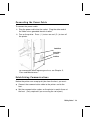
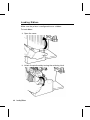
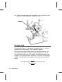
Connecting the Power Cable
To connect the power cable:
1. Plug the power cable into the socket. Plug the other end of
the cable into a grounded electrical outlet.
2. Turn on the printer. Press ( I ) to turn on and ( O ) to turn off
the printer.
Parallel Port
Power Cable
goes here
Serial Port
For information about replacing the fuse, see Chapter 5,
"Care and Maintenance."
Establishing Communications
Before the printer can accept print jobs from the host, you must:
u
Connect the communication cable to the printer and to the
host.
u
Set the communication values on the printer to match those at
the host. (Only required if you are using the serial port.)
Rev. C 3/99
Getting Started 1-3
Connecting the Communication Cable
Make sure the printer is off before connecting
the cable to the communication port.
Ask your System Administrator which method you will use to
communicate with the host:
u
Serial Communication
9 to 25 pin cable (Part #118364)
25 to 25 pin cable (Part #118366)
u
Parallel Communication
IEEE-1284 or Centronics® mode cable (Part #118363)
Connect the communication cable into the appropriate port.
Secure the cable with the connecting screws (serial) or spring
clips (parallel).
D e f a u l t S e r i a l Po r t C o m m u n i c a t i o n Va l u e s
If you are communicating with the host through the serial port,
make sure the printer’s communication values match those at the
host. The factory default values are:
u
Baud:
9600
u
Word Length:
8 bit data frame
u
Stop Bits:
1 stop bit
u
Parity:
none
u
Flow Control:
DTR
To change the printer’s communication values, ask your System
Administrator or see "Setting DIP Switches."
1-4 Getting Started
Rev. C 3/99
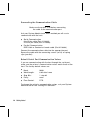
Setting DIP Switches
To change the DIP switch settings, move the switches to the
desired position and then turn on the printer.
If you select Software Controlled, the parameters in Packet F will
override the communication settings. Software Controlled uses
the last sent Packet F settings or the defaults. Turning on the
printer activates the DIP switch settings. Make sure the DIP
switch settings match the printer’s setup for ribbon or supply type.
Upper DIP Switches
Baud Rate
38400
19200
9600
4800
2400
1200
Software Control
Data Bits
7 Data Bits
8 Data Bits
Stop Bits
2 Stop Bits
1 Stop Bit
Parity
Even
Odd
None
Parallel Port
Centronics Mode
IEEE-1284
1
2
3
ON
ON
ON
OFF
OFF
OFF
OFF
ON
OFF
OFF
ON
ON
OFF
OFF
OFF
ON
OFF
ON
OFF
ON
OFF
4
5
6
7
ON
OFF
OFF
OFF
ON
OFF
8
ON
OFF
ON
OFF
OFF
ON
Communication settings at the printer must match those at the host.
Make sure your host is capable of communicating at the speed you
select for the printer.
Rev. C 3/99
Getting Started 1-5
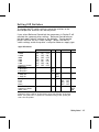
Lower DIP Switches
1
Flow Control
XON/XOFF
RTS/CTS*
DTR
Diagnostics
Normal
Diagnostics Mode
Verifier
No Verifier
Verifier Installed
Supply Type**
Die Cut or Edge
Aperture
Black Mark (center)
Continuous
Center Aperture
Ribbon
Transfer
Direct
Feed Mode
Disable On-Demand
Enable On-Demand
2
3
4
5
6
7
8
ON OFF
OFF ON
OFF OFF
OFF
ON
OFF
ON
OFF OFF
OFF ON
ON OFF
ON ON
OFF
ON
OFF
ON
* Requires a special cable.
** Aperture supplies are tags or labels with holes (or openings) in them.
The supply is sensed using the holes. The holes can be only on the
edge or in the center of the supply. If your aperture supply has holes (or
openings) on the edge, set the DIP switches for edge aperture supplies.
If your aperture supply has holes in the center, set the DIP switches for
center aperture supplies.
1-6 Getting Started
Rev. C 3/99
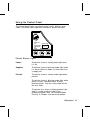
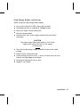
U si n g t h e C o n t r o l Pa n el
The control panel helps you check printer status, displays error
codes, and allows you to perform some basic printer functions.
Printhead
Release
Power
Status Code
Supplies
Paused
Pause
Clear
Feed
123
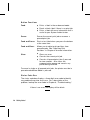
Printer Status Lights
Power:
The printer shows a steady green light when
it is on.
Supplies:
The printer shows a blinking amber light when
it is out of labels or ribbon, or when you have
a supply jam.
Paused:
The printer shows a steady amber light when
paused.
The printer shows a blinking amber light when
there is a data, communication, or data
formatting error. See the status code box for
the error code.
The printer also shows a blinking amber light
when it’s ready to print a label in the
on-demand mode. See "On-Demand Mode
Printing" in Chapter 4 for more information.
Rev. C 3/99
Getting Started 1-7
B u t t o n Fu n c t io n s
Feed:
u
Prints a label in the on-demand mode.
u
Feeds a blank label if there is no print job.
u
Prints a label with error information that is
useful to your System Administrator.
Pause:
Pauses the current print job or resumes a
paused print job.
Feed and Pause:
Prints a test label when you press the buttons
at the same time.
Feed and Clear:
Allows you to adjust print positions from
paused mode. See "Adjusting Print
Positions" in Chapter 4 for more information.
Clear:
u
Clears an error.
u
Cancels the current print job.
u
Cancels all queued print jobs if pressed
for two seconds. Also clears the
communication queue and cancels any
packet being received.
To cancel a single or all queued print jobs, the printer must be in
paused mode before Clear is pressed.
Status Code Box
The status code box displays a three-digit error code to identify
any problem the printer may have. For a description of the
problem, look up the error code in Chapter 6, "Troubleshooting."
If there is no error, the display will be blank.
1-8 Getting Started
Rev. C 3/99
2
LOADING SUPPLIES
This chapter describes how to load:
u
a roll of supply
u
fan-fold supply
u
a roll of tag supply.
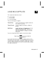
There are three types of supplies:
Thermal Direct
specially treated thermal supplies that do not
use a ribbon for printing.
Thermal Transfer
standard supplies that require a ribbon for
printing.
High Energy
scratch, chemical, and temperature resistant
supplies that require a ribbon able to
withstand high temperatures. See "Using a
High Energy Ribbon" in Chapter 3 for more
information.
If you are using thermal direct supplies, do not load a ribbon.
High energy supplies are only available for
the 9830 printer.
If you switch from black mark to die cut supplies, make sure the
DIP switches are set correctly. The System Administrator can also
send the supply setup packet to change the supply type. Refer to
the Packet Reference Manual for more information about sending
the supply setup packet.
Rev. C 3/99
Loading Supplies 2-1
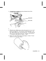
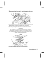
L o a d i n g L a b e l s o r Ta g s
Make sure the printer is configured for the correct supply type.
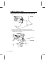
1. Open the cover.
2. Unlock the printhead by turning the retaining latch.
3. Lift printhead assembly using the printhead tab until the
assembly locks into place.
Printhead Tab
Deflector Tab
2-2 Loading Supplies
Rev. C 3/99
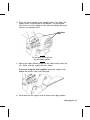
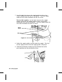
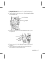
4. Place the roll of supply on the supply holder. For labels, the
supply unrolls from the top or the bottom. For perforated
tags, make sure the supply unrolls from the bottom, because
tag rolls are wound face in.
Supply Holder
Guides
Do not pick up the printer
by the supply holder.
5. Adjust the supply holder guides so the sides barely touch the
roll. Make sure the supply roll turns freely.
If you are using fan-fold supplies, place the supply stack
behind the printer, label side facing up.
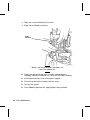
6. Push down on the supply lever to unlock the supply guides.
Rev. C 3/99
Loading Supplies 2-3
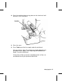
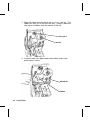
7. Lay the label strip across the supply guide so that a few
inches extend past the front of the printer. Tuck the supply
under the nibs and in between the die cut sensor.
For fan-fold supplies, lay the label strip over the supply
holder and across the supply guide so that a few inches
extend past the front of the printer. Tuck the supply under the
nibs and in between the die cut sensor.
Die Cut
Sensor
Nibs
Supply Lever
8. Adjust the supply guides so they touch the supply. Push up
on the supply lever to lock the supply guides into place.
9. Hold the printhead assembly by the printhead tab while
pressing down on the printhead release.
2-4 Loading Supplies
Rev. C 3/99
10. Close the printhead by pressing down on the thumb well until
you hear it click into place.
Thumb Well
11. Close the cover.
12. Press Feed to position the supply under the printhead.
You may need to adjust the wide/narrow knobs depending on
the width of your supply. See "Adjusting the Wide/Narrow
Knobs" for more information.
If the printer will be unused for extended periods of time, we
recommend leaving the printhead unlatched.
Rev. C 3/99
Loading Supplies 2-5
For Peel Mode (9830 only)
In peel mode, the printer separates the backing paper from the
label. The next label is not printed until the completed one is
removed from the printer. Make sure the printer is configured for
on-demand mode and the correct supply type.
The minimum feed length is 1.5 inches for peel mode. Hold the
leading edge of peeled labels when printing on stock longer than
six inches. You must use non-perforated supplies for peel mode.
Follow the steps for loading supplies from the previous section.
Then, follow these steps after you close the printhead.
1. Remove the labels from the first 10 inches of the backing
paper.
2. Press down on the exit cover tabs to open the exit cover on
the front of the printer.
Exit Cover
2-6 Loading Supplies
Rev. C 3/99
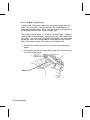
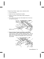
3. Feed the backing paper over the peel bar.
Peel Bar
Lower Opening
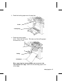
4. Feed the backing paper through the lower opening of the exit
cover. Close the exit cover. Pull down on the backing paper
to remove any slack.
Tear Edge
Backing Paper
When removing the backing paper, pull up across the
saw-toothed tear edge. Make sure the backing paper tears
at the edge.
Rev. C 3/99
Loading Supplies 2-7
5. Close the printer’s cover.
6. Press Feed to position the supply under the printhead.
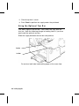
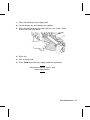
U s i n g t h e O p t i o n a l Te a r B a r
Tear labels against the tear bar. You cannot tear tags with the
tear bar. Note the following change to loading labels if you have
purchased the optional tear bar:
Slide the supply between the tear bar and peel bar.
Tear Bar
Peel Bar
Do not tear both label and backing paper at the same time.
2-8 Loading Supplies
Rev. C 3/99
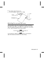
u
Tear labels against the tear bar.
u
Tear backing paper against the tear edge.
Tear Edge
Backing Paper
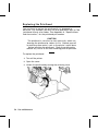
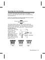
Adjusting the Wide/Narrow Knobs
You may need to adjust the two wide/narrow knobs according to
the width of your supply. For supply that is more than two inches,
adjust the knobs to the wide setting. For supply that is two inches
or less, adjust the knobs to the narrow setting.
You must adjust both of the knobs to
the same position.
If you experience ribbon smudging in cold, dry environments,
adjust the wide/narrow knobs to the wide setting.
Rev. C 3/99
Loading Supplies 2-9
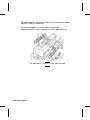
For wide supplies, push down and turn the wide/narrow knobs
clockwise with a screwdriver.
For narrow supplies, turn the wide/narrow knobs
counter-clockwise with a screwdriver until it pops back up.
The adjustment is shown in the wide position.
2-10 Loading Supplies
Rev. C 3/99
3
LOADING RIBBON
This chapter describes how to load a ribbon roll.
There are different ribbon requirements for the three types of
supplies:
Thermal Direct
Supplies
do not use a ribbon for printing.
Thermal Transfer
Supplies
require a ribbon for printing.
High Energy
Supplies
require a ribbon able to withstand high
temperatures.
High energy supplies are only available
for the 9830 printer.
If you are using thermal direct supplies, do not load a ribbon. If
you are using high energy supply, be sure to use a high energy
ribbon. See "Using a High Energy Ribbon" for more information.
If you want to use a high energy ribbon, you must send the supply
setup packet every time the printer is turned on.
Rev. C 3/99
Loading Ribbon 3-1
Loading Ribbon
Make sure the printer is configured to use a ribbon.
To load ribbon:
1. Open the cover.
2. Unlock the printhead by turning the retaining latch.
3-2 Loading Ribbon
3. Lift printhead assembly using the printhead tab until the
assembly locks into place.
Printhead Tab
Deflector Tab
4. Push the deflector tab down.
5. Slide the extra ribbon core on the take-up reel as far as it will
go with the "Monarch This End Out" writing facing out. Use
your empty ribbon core as the take-up core. The take-up core
only fits on the take-up reel one way. (An extra take-up core
is available by ordering part number 117961.)
6. Remove the new ribbon from the package as shown. Do not
wrinkle or crush the new ribbon.
Loading Ribbon 3-3
7. Slide the ribbon onto the back reel as far as it will go. The
ribbon roll only fits on the reel one way. Carefully unwind a
few inches of ribbon from the bottom of the roll.
Take-up Reel
Back Reel
8. Carefully feed the ribbon under both ribbon rollers and
printhead as shown.
Ribbon Roller
Printhead
3-4 Loading Ribbon
9. Align the ribbon and make sure it is straight and centered
throughout the path.
10. Tape the ribbon to the take-up core. Do not tape the ribbon
to the take-up reel.
Take-up Core
Take-up Reel
11. Rotate the take-up core until the MONARCH leader is past
the printhead.
12. Remove any slack in the ribbon by turning the take-up reel
clockwise.
13. Hold the printhead assembly by the printhead tab while
pressing down on the printhead release.
Loading Ribbon 3-5
14. Close the printhead by pressing down on the thumb well until
you hear it click into place. Close the cover.
Thumb Well
Using a High Energy Ribbon
High energy ribbon is an option for the 9830 printer. It enables
you to print on high energy (TUFF-MARK®) supplies.
When you select high energy ribbon for the printer setting, you
are setting the printer to a higher printing temperature. Select
this setting only after you have loaded a high energy ribbon and
supply or it may damage your printhead. To select a high energy
ribbon, send the supply setup packet everytime you turn on the
printer.
The high energy setting is lost when you turn
off the printer.
3-6 Loading Ribbon
High Energy Ribbon Limitations
When using the high energy ribbon option:
u
Use a print speed of 2.5IPS (inches per second).
u
Printhead warranty is reduced to 100,000 inches.
u
Serial bar codes cannot be printed.
u
Do not use peel mode.
u
No more than 20% of the supply should have print (black
coverage).
CAUTION
The high energy ribbon may break or stick to the
supply when more than 20% of the supply
contains print.
u
Only white high energy supply should be used for bar code
printing.
u
Reverse fonts cannot be used.
u
A non-printing area of at least .1 inch (2.54 mm) must exist on
the left and right edge of the ribbon.
u
Do not print horizontal lines or bars.
u
Graphics are limited.
Loading Ribbon 3-7
3-8 Loading Ribbon
4
PRINTING
This chapter explains how to
u
use on-demand mode printing.
u
print an error label.
u
print batch separators.
u
adjust the print positions.
Rev. C 3/99
Printing 4-1
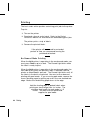
Printing
The host sends online packets containing print jobs to the printer.
To print:
1. Turn on the printer.
2. Download a format and a batch. Refer to the Packet
Reference Manual for information on downloading print jobs.
The printer prints a strip of labels.
3. Remove the printed labels.
If the printer will be unused for extended
periods of time, we recommend leaving the
printhead unlatched.
On-Demand Mode Printing
When the 9820 printer is operating in the on-demand mode, you
must press Feed to print a label. The Paused light blinks when
the label is ready to print.
When the 9830 printer is operating in the on-demand mode, the
next label prints when the previous label is removed from the
printer or when Feed is pressed. The Paused light blinks until all
the labels in the batch are printed. You must use on-demand
printing with peel mode. If you are using peel mode, remove the
excess backing paper by pulling up across the saw-toothed tear
edge. Make sure the backing paper tears at the edge.
Hold the leading edge of peeled labels when
printing on stock longer than six inches. The
minimum feed length for peel mode is 1.5
inches. You must use non-perforated
supplies for peel mode.
4-2 Printing
Printing an Error Label
If the printer displays a data error (errors
0-499), press Feed to print an error label
and continue printing. See your System
Administrator about the error label.
Clearing Batches
All batches are cleared when the printer is turned on. You can
also clear all or a single batch by pressing Clear after the printer
is paused. See "Using the Control Panel" in Chapter 1 for more
information.
Using Batch Separators
A batch separator is a striped label that prints in between
batches. For non-indexed (continuous) supply, the batch
separator is always six inches long. The name of the batch is
shown on the batch separator.
To use batch separators, refer to the Packet Reference Manual.
Printing 4-3
Adjusting Print Positions
You can adjust the supply, print, or margin positions on the printer
by using the control panel buttons. Make sure a batch is not
waiting to print before you adjust the positions.
To change the supply, print, or margin positions:
1. Press Pause.
2. Press Feed and Clear (at the same time) once to select the
supply position, twice to select the print position, and three
times to select the margin position. These buttons act as
toggle switches between the three (supply, print, and margin)
position adjustments.
When you select the position to change, the
current setting is displayed.
3. Press Feed to decrease the current position by one dot or
press Feed for two seconds to decrease the value by 10 dots.
OR
Press Clear to increase the current position by one dot or
press Clear for two seconds to increase the value by 10 dots.
If the position has a negative value, the
supplies light is on.
After you adjust the position (and release the
buttons), the setting is displayed.
4. Press Pause when you are done making adjustments.
Resend the format so these changes take effect. You
cannot change the settings if the printer is paused while
printing a batch. Change the settings after the batch is
done printing.
Review the following definitions for the different print position
adjustments.
4-4 Printing
Supply Position
Adjusts the machine to print at the vertical 0,0
point on the supply. Increase the supply
position to move print up, decrease to move
print down on the label. The range is -300 to
300 dots.
The supply position adjustment should only
be made on inital printer setup. For format
adjustments, change the print position.
Print Position
Adjusts where data prints vertically on the
supply. Increase the print position to move
print up, decrease to move print down. The
range is -99 to 99 dots.
Margin Position
Adjusts where data prints horizontally on the
supply. Increase the margin position to move
print to the right, decrease to move print to
the left. The range is -99 to 99 dots.
Printing the Euro-Dollar Symbol
You can print the Euro-Dollar symbol (c) online by using ~192
(ASCII) code in the data stream. Your System Administrator can
also select the Euro-Dollar symbol by sending the Monetary
Formatting Packet (packet D). If you have purchased the optional
keypad, you can select Euro-Dollar from the Defaults Monetary
Sign Menu.
Printing 4-5
4-6 Printing
CARE AND MAINTENANCE
5
This chapter tells you how to
u
clear label jams
u
clean the printhead and platen roller
u
replace a printhead
u
adjust print contrast
u
replace a fuse.
CAUTION
Do not use sharp objects to clean the printhead. This
may damage the printer and void your warranty.
Rev. C 3/99
Care and Maintenance 5-1
Clearing Label Jams
When you are printing and a jam occurs, the Supplies light on the
printer’s front panel blinks. To clear the jam:
1. Turn off the printer.
2. Open the cover and printhead assembly.
3. If necessary, remove the label roll and ribbon.
4. Remove the jammed labels and reload the label roll.
5. Close the printhead assembly and turn on the printer.
6. Press Feed to position the supply under the printhead.
Cleaning
The rate and frequency at which you print determines how often
you must clean the printer.
You may need to clean the printhead and platen roller:
u
if there is any adhesive build-up in
the supply path
u
after printing approximately six rolls of
supply, after using two ribbons, or
whenever you load new supplies
u
daily if your printer is in an excessively
dirty, hot, or humid environment
u
when you see voids in the print as shown.
You may have to clean the supply sensor more often if you
frequently receive supply error codes.
5-2 Care and Maintenance
To clean the printhead, supply sensor, and platen roller:
1. Turn off the printer.
2. Open the cover and printhead assembly.
3. Remove the label roll and ribbon (when cleaning the
printhead).
4. Press down on the exit cover tabs to open the exit cover on
the front of the printer.
Exit Cover
5. Clean the platen roller with a dry cloth or small brush.
However, if there is adhesive gum build-up on the platen
roller, moisten a cotton swab with isopropyl alcohol. Turn the
platen roller with your finger and run the cotton swab or dry
cloth across it. Make sure the platen roller is clean all the
way around.
Care and Maintenance 5-3
6. Rub the cotton swab across the peel bar and remove any
build-up. The peel bar is only available on the 9830 printer.
7. Moisten another cotton swab with isopropyl alcohol. Rub the
cotton swab across the printhead and remove any build-up.
Die Cut
Sensor
Supply Sensor
8. Rub the cotton swab across the supply sensor and die cut
sensor and remove any build-up.
5-4 Care and Maintenance
9. Clean the build-up in the supply path.
10. Let the printer dry and reload your supplies.
11. Close the exit cover by pushing firmly on it as shown. Both
latches will click into place.
12. Close the cover and printhead assembly.
13. Turn on the printer.
14. Press Feed to position the supply under the printhead.
Resend your format, batch, and
check digit packets.
Care and Maintenance 5-5
Replacing the Printhead
You may have to replace the printhead if it is damaged or
worn-out. For example, you may see 616 (bad dot or dots) or 768
(printhead failure) error codes. See Appendix A, "Specifications
and Accessories," for the printhead part number.
CAUTION
The printhead is sensitive to static electricity, which can
damage the printhead or reduce its life. Ground yourself
by touching some metal, such as the printer’s metal base,
before touching the printhead. Clean the printhead to
remove any salt or oil left from handling prior to operation.
To replace the printhead:
1. Turn off the printer.
2. Open the cover.
3. Unlock the printhead by turning the retaining latch.
5-6 Care and Maintenance
4. Press forward and down on the two latches on top of the
printhead assembly as shown. The printhead will drop down.
5. Lift the printhead assembly using the printhead tab and push
back until the printhead assembly clicks into place.
6. Carefully unplug the cable from the printhead as shown.
CAUTION
The printhead is sensitive to static electricity, which can
damage the printhead or reduce its life. Ground yourself
by touching some metal, such as the printer’s metal base,
before touching the printhead.
7. Carefully plug the cable into the new printhead.
Care and Maintenance 5-7
8. Align the new printhead with the tabs.
9. Snap the printhead into place.
Do not
touch here
Make sure the printhead cable does not
touch the ribbon roll.
10. Clean the new printhead with a cotton swab dipped in
isopropyl alcohol to remove any salt or oil left from handling.
11. Let the printhead dry and reload your supplies.
12. Close the printhead assembly and the cover.
13. Turn on the printer.
14. Press Feed to position the supply under the printhead.
5-8 Care and Maintenance
Adjusting the Print Contrast
You may need to adjust the print contrast if the printing is too light
or too dark. Having the correct print contrast is important
because it affects how well your bar codes scan and how long
your printhead lasts.
Using a thin screwdriver, turn contrast knob clockwise for darker
print; turn counter-clockwise for lighter print.
You only have to turn the contrast
adjuster slightly.
Your System Administrator can adjust the print contrast by
sending the print control packet. Refer to the Packet Reference
Manual for more information. We recommend you check the bar
code print quality with a bar code verifier. If you do not have a
bar code verifier or
scanner, check the bar
code visually. A bar code
that is in spec has
complete bars, clear
spaces, and small
alphanumeric characters
look complete. An in
Contrast Knob
spec bar code may not
look as good as one that
is too dark, but it has the
highest scan rate.
Dark
IN SPEC
Light
Care and Maintenance 5-9
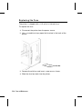
Replacing the Fuse
The printer is shipped with a 115 volt or a 230 volt fuse.
To replace the fuse:
1. Disconnect the printer from the power source.
2. Use a screwdriver to pry open the fuse box in the back of the
printer.
Fuse
Fuse Box
3. Remove the old fuse and insert a new one as shown.
4. Slide the fuse box back into the printer.
5-10 Care and Maintenance
TROUBLESHOOTING
6
This chapter provides
u
information about printing a test label.
u
solutions to minor printing problems.
u
explanations of error messages you may receive while
using the printer.
Rev. C 3/99
Troubleshooting 6-1
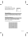
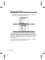
P r i n t i n g a Te s t L a b e l
To print test labels:
Press Feed and Pause simultaneously. Hold for one second
and release. Labels similar to these print:
The first label shows the printer’s configuration by packet (A-G).
The second label shows the model number, software version,
stock count, voltage, print contrast, printhead resistance, number
of bad dots, installed options, and DIP switch settings. The test
label for the 9830 printer also shows an inch count for the high
energy ribbon.
If test labels do not print, press Feed and try again. If that does
not solve the problem, call Technical Support.
6-2
Troubleshooting
Rev. C 3/99
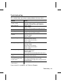
Tr o u b l e s h o o t i n g
This section helps you correct some problems that may occur.
Problem
Action
Error message appears
during startup.
Turn off the printer, wait fifteen seconds and
then turn on the printer. Call Technical
Support if the error message reappears.
Check supply.
Check ribbon.
Send a corrected format and batch packet.
Set wide/narrow knobs correctly.
Clean the printhead.
Send a corrected format packet.
Clean the printhead.
Change supply.
Check ribbon.
Change supply.
Adjust the print contrast.
Check wide/narrow knobs.
Check ribbon.
Clean the printhead.
Change supply.
Adjust the print contrast.
Check wide/narrow knobs.
Check ribbon.
Clean the printhead.
Change supply type.
Check ribbon.
Leave printhead unlatched when not in use.
Use a print speed of 2.5 IPS.
Adjust the print contrast.
Carefully remove the backing paper. Make
sure the backing paper tears at the
saw-toothed tear edge when using backfeed
and peel mode.
Clean supply sensors.
Does not print.
Does not feed.
Partially printed data.
Printing shadows or
smears.
Light printing.
Heavy printing.
Voids in printing.
Serial bar codes do not
scan.
Backing paper is
wrapped around platen
or peel roller.
Blank labels print or 750
series errors.
If you cannot fix a problem, call Technical Support.
Rev. C 3/99
Troubleshooting 6-3
Error Messages
You may receive the following types of error messages:
u
Data Errors
u
Communication Errors
Some errors numbered 400-438 and 500-574 are internal
software errors. Errors numbered 900-999 are hard printer
failures. If you cannot clear an error, turn off the printer, wait
several seconds and then turn on the printer. Call Technical
Support if you receive any error message not listed in this chapter.
Data Errors
Errors 001 to 405 and 429 to 435 are data errors. This type of
error indicates that incorrect data was sent to the printer, and the
printer is ignoring it. Your System Administrator should correct
the packet and send it back to the printer.
6-4
Error
Description/Action
001
Format ID number must be 1 to 999.
002
Name must be 1 to 8 characters inside quotes.
003
Action must be A (add) or C (clear).
004
Supply length is invalid.
005
Supply width is invalid.
006
Storage device must be R (volatile RAM).
007
Unit of measure must be E (English), M (Metric), or G
(Dots).
010
Field ID number is outside the range 0 to 999.
011
Field length exceeds 2710.
Troubleshooting
Rev. C 3/99
012
Row field position is greater than the maximum stock
dimension.
013
Column field position is greater than the maximum stock
dimension.
014
Font selector is invalid.
015
Character rotation must be 0 (0 degree), 1 (90 degree),
2 (180 degree), or 3 (270 degree).
016
Field rotation must be 0 (0 degree), 1 (90 degree), 2
(180 degree), or 3 (270 degree).
017
Field restriction must be V (variable) or F (fixed).
018
Code page selection defined in the field must be 0
(Internal), 1 (ANSI), 2 (DOS 437), or 3 (DOS 850).
020
Vertical magnification must be 1 to 7.
021
Horizontal magnification must be 1 to 7.
022
Color must be B, D, O, R, or W.
023
Intercharacter gap must be 0 to 99 dots.
024
Field justification must be B (balanced), C (centered), E
(end), L (left), or R (right).
025
Data length is too long.
030
Bar code height must be at least 20 (English), 51
(Metric), 40 (Dots), or is not within the supply
dimensions.
031
Human readable option must be 0, 1, 5, 6, 7, or 8.
032
Bar code type is invalid.
033
Bar code density is invalid.
040
Line thickness must be 0 to 99 dots.
Rev. C 3/99
Troubleshooting 6-5
6-6
041
Line direction must be 0, 90, 180, or 270.
042
The line segment or box end row is defined outside of
printable area.
043
The line segment or box end column is defined outside
of printable area.
044
Dot pattern for line or box must be "".
045
Line length is defined beyond the maximum length.
046
Line type must be S (segment) or V (vector).
051
Imaging mode in the graphic header must be 0.
101
Format referenced by batch not in memory.
102
Print quantity is outside the range 0 to 32000.
104
Batch mode must be N (new) or U (update).
105
Batch separator must be 0 (Off) or 1 (On) in the batch
control field.
106
Print multiple is outside the range 1 to 999.
107
Cut multiple is outside the range 0 to 999.
108
Multiple part supply is outside the range 1 to 5.
109
Reserved for knife usage.
200
Option number must be 1, 4, 30, 31, 42, 50, 60, or 61.
201
Copy length is outside the range 0 to 2710.
202
Copy start position must be 1 to 2710.
203
Destination start position must be 1 to 2710.
204
Source field must be 0 to 999.
Troubleshooting
Rev. C 3/99
205
Copy type must be 1 (Copy after rules) or 2 (Copy
before rules).
206
Increment/Decrement selection must be I (increment) or
D (decrement).
207
Incrementing start position must be 0 to 2710.
208
Incrementing end position must be 0 to 2710.
209
The incrementing amount must be 0 to 999.
210
Security value for a PDF417 bar code must be 0 to 8.
211
Narrow element value is less than 1 or greater than 99.
212
Wide element value is less than 1 or greater than 99.
213
Dimension must be 1 to 30 for a column or 3 to 90 for a
row.
214
Truncation code must be S (standard) or T (truncated
bar code).
215
Aspect code must be C (columns) or R (rows).
216
Option definition must be S (set) or T (template).
217
Input device must be D (Default), H (Host), K
(Keyboard), N (None), or S (Scanner).
218
Pad direction must be L (from left) or R (from right).
219
Pad character is outside the range 0 to 255.
220
Check digit selection must be G to generate check digit.
221
Primary or secondary price format is outside the range
1 to 15.
222
Data type restriction is outside the range of 1 to 6.
223
Option is not valid for the field.
Rev. C 3/99
Troubleshooting 6-7
6-8
224
Bar code Intercharacter gap must be 0 to 99 in printer
dots.
251
Power up mode must be 0 (online) or 1 (offline).
252
Language selection must be 0 (English).
253
Batch separator code must be 0 (off) or 1 (on) in the
system setup packet.
254
Slash zero selection must be 0 (standard zero) or 1
(slash zero).
255
Supply type must be 0 (black mark) or 1 (die cut).
256
Ribbon selection must be 0 (direct) or 1 (transfer).
257
Feed mode must be 0 (continuous) or 1 (on-demand).
258
Supply position is outside the range.
259
Contrast adjustment must be -390 to 156 dots.
260
Print adjustment must be -99 to 99 dots.
261
Margin adjustment must be -99 to 99 dots.
262
Speed adjustment is invalid.
263
Primary monetary symbol is invalid.
264
Secondary symbol selection must be 0 (none) or 1
(print secondary sign).
265
Monetary decimal places must be 0 to 3.
266
Character string length in Packet E must be 5 (MPCL
control characters) or 7 (ENQ/IMD command character).
267
Baud rate selection must be 0 (1200), 1 (2400), 2
(4800), 3 (9600), 4 (19.2), or 5 (38.4).
268
Word length selection must be 0 (7 bits) or 1 (8 bits).
Troubleshooting
Rev. C 3/99
269
Stop bits selection must be 0 (1 bit) or 1 (2 bits).
270
Parity selection must be 0 (none), 1 (odd), or 2 (even).
271
Flow control selection must be 0 (none), 1 (DTR/DSR),
2 (CTS/RTS), or 3 (XON/XOFF).
272
Internal code page selection must be 0 (Internal), 1
(ANSI), 2 (DOS 437), or 3 (DOS 850).
273
Cut adjustment must be -300 to 300 dots.
282
RS232 Trailer string is too long. Use a maximum of 3
characters.
283
ENQ Trailer string is too long. Use a maximum of 3
characters.
284
The buffer type must be T (transmit), R (receive), I
(image), F (format, batch data, and graphics), D
(downloadable fonts), or V (vector/scalable fonts).
285
The storage device type must be N (non-volatile RAM)
or R (volatile RAM).
286
The buffer size is invalid.
287
The printhead width is invalid.
290
Action must be 0 (disable) or 1 (enable) for Backfeed
Control.
291
Dispense position must be 50 to 200 dots and/or the
backfeed distance is greater than the dispense position.
292
Backfeed distance must be 10 to 200 dots.
310
Check digit scheme number must be 1 to 10.
311
Modulus must be 2 to 11.
314
Check digit algorithm must be D (sum of digits) or P
(sum of products).
Rev. C 3/99
Troubleshooting 6-9
325
Duplicating direction must be 0 or 1.
327
Amount of row adjustment must be 0 to 999.
328
Duplicate count must be 0 to 999.
340
Bitmap line encoding must be H (Hex) or R (Run length).
350
Font selector must be 1 to 9999.
351
Font data length must be 68 to 16384.
352
Insufficient font memory is available for the downloaded
font.
380
Job request is outside the range 0 to 4.
400
Invalid character following {.
401
Internal software failure. Call Technical Support.
402
Field separator is not in the expected location.
403
Field separator was not found.
404
The number or string that is currently being processed
is too long.
405
Too many fields exist in the format.
Communication Failures
Errors 409 to 413 usually indicate a communication failure.
These errors happen when the host and the printer cannot
communicate. Ask your System Administrator for help.
6-10
Error
Description/Action
409
Printer memory is full.
410
Parity mismatch.
411
Framing error (baud rate mismatch).
Troubleshooting
Rev. C 3/99
412
Flow control mismatch.
413
Receive buffer is full. Check flow control settings.
414
Internal keyboard buffer is full or you need a new
keypad.
427
Format name must be 1 to 8 characters inside quotes or
a printer-assigned name ("").
428
Batch name is invalid or graphic not found.
429
A field number appears more than once in a format.
430
The format uses a graphic file that cannot be found.
433
The batch references a field number that does not exist
in the format.
497
Error occurred during the parallel port loop back test.
499
Error occurred during the serial port loop back test.
Data Formatting Errors
Errors 571 to 618 are data formatting errors. This type of error
happens when a field prints incorrectly. Your System
Administrator can correct the format, batch, or graphic packet and
send the print job again. For errors 571 to 614, the printer will
still print, but the data may be incomplete, missing, or wrong.
Error
Description/Action
571
UPC or EAN bar code data length in the batch doesn’t
fit the format.
572
Batch data doesn’t fit the format, the field contains
blanks, or data mismatch.
573
Batch data in price field doesn’t fit the format or the
field contains blanks.
Rev. C 3/99
Troubleshooting 6-11
574
Batch data in check digit scheme doesn’t fit the format,
or, the field contains blanks.
575
The graphic included in your format could not be found.
600
Imaging error because the batch was refused.
601
An error occurred while the batch was imaging.
602
The batch was not found during imaging.
611
Font, bar code, or density in the batch doesn’t fit the
format.
612
Batch data is missing or doesn’t match the format.
613
Reference point off tag.
614
Portion of field off tag.
615
Bar code width is greater than 16 inches, or keywords
on PDF 417 bar code exceed 928.
616
A bad dot falls on a bar code and the dot cannot be
shifted. Call Customer Service to order a new
printhead or printhead kit.
618
Magnification must be 1 to 7.
Machine Faults
Errors 700 to 765 happen when there is a problem with the printer.
6-12
Error
Description/Action
700
An error is pending, and the printer cannot continue
with the batch.
701
Printer received a command that it cannot execute
while it is running.
702
Check your printer’s SETUP settings.
Troubleshooting
Rev. C 3/99
703
The printer sensed a calibration of different-sized black
marks.
704
Printer didn’t detect a sense mark within the maximum
feed length or is out of supplies. Check or load
supplies.
705
Invalid batch received.
750
Printhead is overheated, turn off the printer to let it cool.
751
Printer didn’t detect a sense mark when expected.
752
Printer detected a sense mark in the wrong place.
753
Printer detected a sense mark that is too long.
754
Out of ribbon or ribbon jam. Check or load ribbon.
Remove any slack in the ribbon by turning the take-up
reel clockwise.
755
Printhead is open. Close the printhead.
756
Out of supplies. Load supplies.
757
Reload supplies (supply length mismatch).
758
The supply was not seen or the on-demand sensor is
not working correctly. Check for a supply jam. Clear
the supply path or reload supplies. This error may
occur if you remove a label too quickly in the
on-demand mode. The printer does not recalibrate
after this error.
759
Knife is not moving. Call Technical Support.
760
Knife jam. Remove any jammed tags from the knife.
Call Technical Support.
761
Stacker is full or jammed. Empty the stacker or clear
the jam before continuing. The printer does not
recalibrate after this error.
Rev. C 3/99
Troubleshooting 6-13
762
Low battery. Recharge the battery.
763
Waiting to dispense label. Press Feed.
764
Verifier failure. Press Clear to clear the error and
continue printing. A blank label feeds and the last label
reprints.
765
The printhead has less than four bad dots. The printer
can shift bar code fields to avoid bad dots. Press Clear
to continue printing. Print a test label to confirm the
number of bad dots.
768
Printhead has more than 10 bad dots or is not
connected. Make sure the printhead is connected. If
necessary, call Customer Service to order a new
printhead or printhead kit.
770
The print motor is not ready. Call Technical Support.
771
The format specified by the application was not found.
Reload your application and format and try again.
790
The printer is busy. Wait until the printer is idle (not
receiving data or no batch waiting to print) before you
send any packets. This error may occur when you try
to print a test label if the printer is busy.
791
The printer has an error pending. Turn off the printer.
Wait 15 seconds and turn it back on. Resend the
packets.
792
The printer is not initialized. Call Technical Support.
793
The printer job queue is full. Turn off the printer. Wait
15 seconds and turn it back on. Resend the packets.
Errors numbered 900-999 are hard printer failures. Call Service if
you receive these messages.
6-14
Troubleshooting
Rev. C 3/99
Rev. C 3/99
Troubleshooting 6-15
A
S P E C I F I C AT I O N S &
ACCESSORIES
Printer
Height:
12.5 inches (318 mm)
Width:
12 inches (305 mm)
Depth:
13 inches (330 mm)
Weight:
25 lb. (11 kg) for 9820 printer
29 lb. (13 kg) for 9830 printer
Shipping Weight:
29 lb. (13 kg) for 9820 printer
33 lb. (15 kg) for 9830 printer
Power:
115 Vac, 60Hz, 100 Vac, 50/60 Hz, 230 Vac, 50Hz
Operating Limits:
For Thermal Transfer (ribbon) 40° to 95° F
(4° to 35° C)
For Thermal Direct 40° to 104° F
(4° to 40° C)
Printhead:
Thermal at 4 inches (102 mm) wide
203 dpi (8.0 dots per mm)
Printing Method:
Thermal Transfer (ribbon) or Thermal Direct
Print Speed:
u
2.5 IPS (64 mm) for all serial bar codes
u
2.5 IPS (64 mm), 4.0 IPS (102 mm), or 6.0 IPS (152
mm) for other operations
We recommend a print speed of 2.5 IPS for labels less
than two inches long using backfeed or on-demand
mode printing.
Rev. C 3/99
Specifications & Accessories A-1
Supplies
For high temperature or high humidity environments, contact
Monarch for supply recommendations. Non-indexed supply
(continuous) does not have perforations or black marks and must
be used in continuous mode. Use continuous supply with the
optional tear bar.
Supply Types:
Thermal Transfer or Direct
Supply Widths:
1.2 inches (31 mm) minimum
4.25 inches (108 mm) maximum
Supply Lengths:
1 inch (25 mm) minimum
12.0 inches (305 mm) maximum for 9820
printer
16.0 inches (406 mm) maximum for 9830
printer
Ribbon Specification
Ribbon Storage:
Do not leave ribbon in direct sunlight, high
temperatures, or high humidity.
Ribbon Type:
Standard or High Energy (only available on
9830 printer)
Ribbon Widths:
1.3 inches (33 mm), 1.6 inches (41 mm,)
2.16 inches (55 mm), 3.15 inches (80 mm),
4.13 inches (105 mm)
Ribbon Length:
23,600 inches (600 meters)
About Ribbons
The width of the ribbon must be greater than the supply width.
Since some supplies are more abrasive to printheads than others,
using a ribbon wider than your supply helps protect the printhead.
Replacement printheads are expensive.
A-2 Specifications & Accessories
Rev. C 3/99
Accessories
u
Internal TwinAx/CoAx Protocol Converter Part # 117532
u
LAN Print Server
u
Printhead Assembly Kit Part # 11797101, 03, or 06 (available
as single, three, or six pack)
u
Ribbon Take-up Core Part # 11796120, 30, or 40 (available in
two, three, or four inches)
u
High Energy Ribbon (9830 printer only)
u
Tear Bar
u
Metal Cover (9830 printer only)
RJ-45 Connector (10BaseT) Part # 11753101
BNC Connector (10Base2) Part # 11753102
Rev. C 3/99
Specifications & Accessories A-3
A-4 Specifications & Accessories
Rev. C 3/99
GLOSSARY
The following terms will help you use this manual.
continuous mode
Mode in which the printer prints all the labels in the
batch without stopping.
download (send)
Transmission of data from the host to your printer.
format
Supply layout or design, which the System
Administrator downloads as a format packet to your
printer.
host
Any mainframe, minicomputer, data collect terminal, or
personal computer sending data to the printer.
LCD
Display on the printer used to indicate printer conditions
and problems.
MONARCH leader
Wrap around a new roll of ribbon with Monarch printed
on it.
on-demand mode
Mode in which the printer stops after each label to allow
you to remove it.
print job
Actual data printed on a label or tag. The host may
download the print job together with the format, or as a
separate packet. The print job is also called a "batch."
online
Direct communication between a computer and the
printer.
Supply Sensor
Senses whether supply is loaded or needs to be loaded
in the printer. Located in the supply path.
Supplies
Labels used for printing.
System
Administrator
Person responsible for creating and downloading
packets.
Rev. C 3/99