1
Monarch®
9820™/ 9830™/ 9835™
Printers
al
hnic
c
e
eT
y th
b
d
lishe
Pub
TC9830SM Rev. B 7/98
ted
Prin
.
t
en
artm
p
e
sD
tion
a
c
i
mun
Com
e
in t h
.A.
U.S
©1996 Monarch Marking Systems, Inc. All rights reserved.
Table of Contents
CHAPTER 1 PRINTER OVERVIEW & INSTALLATION--------------------------------------------- 1
PRINTER FEATURES---------------------------------------------------------------------------------------------------------------1
PRINTER OPTIONS -----------------------------------------------------------------------------------------------------------------1
PRINTER SPECIFICATIONS------------------------------------------------------------------------------------------------------1
STOCK SPECIFICATIONS---------------------------------------------------------------------------------------------------------2
UNPACKING THE PRINTER ------------------------------------------------------------------------------------------------------3
DOCUMENTATION ------------------------------------------------------------------------------------------------------------------3
SETTING DIP SWITCHES ---------------------------------------------------------------------------------------------------------3
FUSE REPLACEMENT--------------------------------------------------------------------------------------------------------------4
CONNECTING TO A HOST--------------------------------------------------------------------------------------------------------4
CHAPTER 2 FUNCTIONAL DESCRIPTION----------------------------------------------------------- 7
OVERVIEW OF MODULES--------------------------------------------------------------------------------------------------------7
Power Transformer Assembly --------------------------------------------------------------------------------------------------8
Inlet Power Module -------------------------------------------------------------------------------------------------------------8
Power Transformer -------------------------------------------------------------------------------------------------------------8
Bridge Rectifier ------------------------------------------------------------------------------------------------------------------8
CONTROL BOARD ASSEMBLY--------------------------------------------------------------------------------------------------8
Functional Description ------------------------------------------------------------------------------------------------------------8
Power Conversion --------------------------------------------------------------------------------------------------------------9
Memory ----------------------------------------------------------------------------------------------------------------------------9
Flash Memory-----------------------------------------------------------------------------------------------------------------9
DRAM Memory ---------------------------------------------------------------------------------------------------------------9
SRAM Memory ---------------------------------------------------------------------------------------------------------------9
Printer Control -------------------------------------------------------------------------------------------------------------------9
Data Handling -----------------------------------------------------------------------------------------------------------------9
Printhead Thermal Control-------------------------------------------------------------------------------------------------9
Print Imaging ------------------------------------------------------------------------------------------------------------------9
Motion Control ----------------------------------------------------------------------------------------------------------------9
Platen Drive Interface-------------------------------------------------------------------------------------------------------9
Ribbon Drive Interface------------------------------------------------------------------------------------------------------9
Analog to Digital Conversion ----------------------------------------------------------------------------------------------9
Supply Detection & Tracking System -----------------------------------------------------------------------------------9
Operator Control Panel --------------------------------------------------------------------------------------------------------9
Communications ----------------------------------------------------------------------------------------------------------------9
RS-232 interface ----------------------------------------------------------------------------------------------------------- 10
Centronics IEEE-1284 Parallel Interface----------------------------------------------------------------------------- 10
IEEE 1284 Bi-Directional Parallel Interface ------------------------------------------------------------------------- 10
Contrast Control --------------------------------------------------------------------------------------------------------------- 10
Hardware Power-up Settings (DIPS) ------------------------------------------------------------------------------------- 10
Peel Module Assembly ------------------------------------------------------------------------------------------------------ 10
PRINT ASSEMBLY----------------------------------------------------------------------------------------------------------------- 10
Thermal Printhead ------------------------------------------------------------------------------------------------------------ 10
Ribbon Supply & Take-up Spools----------------------------------------------------------------------------------------- 10
Ribbon Transfer Rollers ----------------------------------------------------------------------------------------------------- 10
Ribbon Spool Drive Motors ------------------------------------------------------------------------------------------------- 11
Supply Deflector and Bi-Cell Emitter (IR LED) ------------------------------------------------------------------------ 11
Ribbon Transfer Rollers ----------------------------------------------------------------------------------------------------- 11
Functional Description ---------------------------------------------------------------------------------------------------------- 11
Ribbon Drive Operation ----------------------------------------------------------------------------------------------------- 11
Printing--------------------------------------------------------------------------------------------------------------------------- 11
i
FEED ASSEMBLY------------------------------------------------------------------------------------------------------------------ 11
Platen Module------------------------------------------------------------------------------------------------------------------ 11
24VDC Stepper Motor ------------------------------------------------------------------------------------------------------- 11
Lower Supply Guide and Bi-Cell Sensor -------------------------------------------------------------------------------- 11
Printhead Latch ---------------------------------------------------------------------------------------------------------------- 11
Functional Description ---------------------------------------------------------------------------------------------------------- 11
Printhead Locking ------------------------------------------------------------------------------------------------------------- 12
SUPPLY HOLDER ASSEMBLY------------------------------------------------------------------------------------------------- 12
Functional Description ---------------------------------------------------------------------------------------------------------- 12
CONTROL PANEL ASSEMBLY------------------------------------------------------------------------------------------------- 12
Functional Description ---------------------------------------------------------------------------------------------------------- 12
CHAPTER 3 TROUBLESHOOTING------------------------------------------------------------------- 13
PRELIMINARY CHECK ----------------------------------------------------------------------------------------------------------- 13
ANALYZING FAILURE DURING POWER UP ------------------------------------------------------------------------------ 13
EVALUATION OF A 616 ERROR (DOT SHIFTING FAILED) ----------------------------------------------------------- 13
EVALUATION OF A 704 ERROR (OUT OF SUPPLY)-------------------------------------------------------------------- 13
EVALUATION OF A 754 ERROR (OUT OF RIBBON)-------------------------------------------------------------------- 14
EVALUATION OF A 755 ERROR (PRINTHEAD OPEN) ----------------------------------------------------------------- 14
EVALUATION OF A 765 ERROR (PRINTHEAD FAILURE)------------------------------------------------------------- 14
EVALUATION OF THE CONTROL BOARD ASSY. ----------------------------------------------------------------------- 14
EVALUATION OF COMMUNICATIONS -------------------------------------------------------------------------------------- 14
GENERAL TROUBLESHOOTING SUGGESTIONS----------------------------------------------------------------------- 15
CHAPTER 4 DIAGNOSTICS ---------------------------------------------------------------------------- 19
POWER-UP SELF-TEST --------------------------------------------------------------------------------------------------------- 19
NV RAM ByteTest---------------------------------------------------------------------------------------------------------------- 19
Version String Mismatch ------------------------------------------------------------------------------------------------------- 19
System Restart Condition --------------------------------------------------------------------------------------------------- 19
Printhead Dot Resistance ------------------------------------------------------------------------------------------------------ 19
TEST LABEL (LEVEL 1) ---------------------------------------------------------------------------------------------------------- 19
SERVICE DIAGNOSTICS -------------------------------------------------------------------------------------------------------- 20
Accessing Diagnostic Modes-------------------------------------------------------------------------------------------------- 20
Data Dump Mode ---------------------------------------------------------------------------------------------------------------- 20
Serial Loop Back Test----------------------------------------------------------------------------------------------------------- 21
Parallel Port Test----------------------------------------------------------------------------------------------------------------- 21
Diagnostics Test Mode---------------------------------------------------------------------------------------------------------- 21
Performing a Virgin Printer Reset----------------------------------------------------------------------------------------- 21
Printing a Test Label --------------------------------------------------------------------------------------------------------- 21
CHAPTER 5 TESTS AND ADJUSTMENTS --------------------------------------------------------- 23
SERVICE TESTS ------------------------------------------------------------------------------------------------------------------- 23
CN6 Power Supply------------------------------------------------------------------------------------------------------------ 23
Continuity Tests ------------------------------------------------------------------------------------------------------------------ 23
Transformer - Primary Side ------------------------------------------------------------------------------------------------ 23
Transformer - Secondary Side--------------------------------------------------------------------------------------------- 23
Bridge Rectifier ---------------------------------------------------------------------------------------------------------------- 23
Head Open Sensor ----------------------------------------------------------------------------------------------------------- 23
Displaying Machine/Service Totals --------------------------------------------------------------------------------------- 23
Print Contrast Adjustment------------------------------------------------------------------------------------------------------ 24
Platen Motor Gear Adjustment ----------------------------------------------------------------------------------------------- 24
Ribbon Tension Adjustment --------------------------------------------------------------------------------------------------- 24
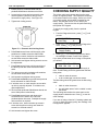
CHECKING SUPPLY QUALITY------------------------------------------------------------------------------------------------- 25
ii
TC9830SM Rev. B 7/98 Confidential
CHAPTER 6 SERVICE PROCEDURES -------------------------------------------------------------- 27
MAINTENANCE OVERVIEW---------------------------------------------------------------------------------------------------- 27
GENERAL SAFETY TIPS -------------------------------------------------------------------------------------------------------- 27
CONTROL PANEL REMOVAL -------------------------------------------------------------------------------------------------- 27
COVER HOUSING REMOVAL-------------------------------------------------------------------------------------------------- 27
POWER TRANSFORMER ASSEMBLY -------------------------------------------------------------------------------------- 28
Transformer Removal----------------------------------------------------------------------------------------------------------- 28
Bridge Rectifier Removal ------------------------------------------------------------------------------------------------------ 28
AC Inlet Removal ---------------------------------------------------------------------------------------------------------------- 28
Control Board Assy. Removal ------------------------------------------------------------------------------------------------ 29
PRINT ASSEMBLY----------------------------------------------------------------------------------------------------------------- 29
Bi-Cell Emitter Removal-------------------------------------------------------------------------------------------------------- 30
Upper Supply Guide Removal ------------------------------------------------------------------------------------------------ 30
Printhead Module Removal---------------------------------------------------------------------------------------------------- 30
Ribbon Spool Assembly Removal ------------------------------------------------------------------------------------------- 30
Ribbon Roller Assembly Removal ------------------------------------------------------------------------------------------- 30
DC Ribbon Motor Removal ---------------------------------------------------------------------------------------------------- 30
Print Assembly Removal ------------------------------------------------------------------------------------------------------- 31
FEED ASSEMBLY------------------------------------------------------------------------------------------------------------------ 31
Latch Fascia Removal ---------------------------------------------------------------------------------------------------------- 31
Platen Module Removal-------------------------------------------------------------------------------------------------------- 31
Platen Module Replacement -------------------------------------------------------------------------------------------------- 32
Bi-Cell Sensor Removal-------------------------------------------------------------------------------------------------------- 32
Lower Supply Guide Removal ------------------------------------------------------------------------------------------------ 32
Bi-Cell Sensor Replacement -------------------------------------------------------------------------------------------------- 32
Lower Supply Guide ------------------------------------------------------------------------------------------------------------- 33
Replacement ---------------------------------------------------------------------------------------------------------------------- 33
SUPPLY HOLDER------------------------------------------------------------------------------------------------------------------ 33
Supply Holder Removal -------------------------------------------------------------------------------------------------------- 33
PLATEN MOTOR ------------------------------------------------------------------------------------------------------------------- 33
Platen Motor Removal ---------------------------------------------------------------------------------------------------------- 33
PEEL MODULE---------------------------------------------------------------------------------------------------------------------- 33
Peel Module Removal ---------------------------------------------------------------------------------------------------------- 33
Peel Motor Replacement------------------------------------------------------------------------------------------------------- 33
CHAPTER 7 USING FLASH----------------------------------------------------------------------------- 35
FLASH DOWNLOADING PROCEDURES ----------------------------------------------------------------------------------- 35
CHAPTER 8 SUPPLY SENSING SYSTEMS -------------------------------------------------------- 37
SUPPLY DETECTION/TRACKING SYSTEM ------------------------------------------------------------------------------- 37
SUPPLY DEFLECTOR/BI-CELL EMITTER (IR LED) --------------------------------------------------------------------- 37
LOWER SUPPLY GUIDE/BI-CELL SENSOR ------------------------------------------------------------------------------- 38
SUPPLY FEEDING----------------------------------------------------------------------------------------------------------------- 38
SUPPLY SENSING----------------------------------------------------------------------------------------------------------------- 38
MECHANICAL ADJUSTMENTS ------------------------------------------------------------------------------------------------ 39
Bi-Cell Sensor Adjustment----------------------------------------------------------------------------------------------------- 39
REPLACING A SENSOR --------------------------------------------------------------------------------------------------------- 40
SENSOR SETUP WITH VERSION 5.2 OR GREATER------------------------------------------------------------------- 41
POWER UP SENSOR RECOGNITION--------------------------------------------------------------------------------------- 41
Performing a Sensor Display Test ------------------------------------------------------------------------------------------- 42
TC9830SM Rev. B 7/98 Confidential
iii
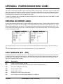
APPENDIX A PRINTER ERROR/STATUS CODES ----------------------------------------------- 43
READING AN ERROR LABEL -------------------------------------------------------------------------------------------------- 43
DATA ERRORS (001 - 499)------------------------------------------------------------------------------------------------------ 43
COMMUNICATION FAILURES (410 - 499) ---------------------------------------------------------------------------------- 47
DATA FORMATTING FAILURES (571 - 619) ------------------------------------------------------------------------------- 48
MACHINE FAULTS (700 - 766) ------------------------------------------------------------------------------------------------- 48
HARD PRINTER FAULTS (900 - 910)----------------------------------------------------------------------------------------- 50
FLASH FAULTS (930 - 940) ----------------------------------------------------------------------------------------------------- 50
FAULTS (950 - 999) ---------------------------------------------------------------------------------------------------------------- 50
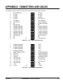
APPENDIX B CONNECTORS AND CABLES------------------------------------------------------- 51
Daughter Board Connectors--------------------------------------------------------------------------------------------------- 55
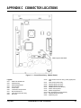
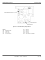
APPENDIX C CONNECTOR LOCATIONS ---------------------------------------------------------- 57
APPENDIX D MODEL 928 STACKER ---------------------------------------------------------------- 59
SPECIFICATIONS------------------------------------------------------------------------------------------------------------------ 59
FUNCTIONAL DESCRIPTION -------------------------------------------------------------------------------------------------- 59
INSTALLATION --------------------------------------------------------------------------------------------------------------------- 59
TROUBLESHOOTING------------------------------------------------------------------------------------------------------------- 60
Error Messages ------------------------------------------------------------------------------------------------------------------- 60
Alignment -------------------------------------------------------------------------------------------------------------------------- 60
CABLES AND CONNECTORS-------------------------------------------------------------------------------------------------- 60
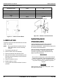
LUBRICATION----------------------------------------------------------------------------------------------------------------------- 62
MAINTENANCE PROCEDURES ----------------------------------------------------------------------------------------------- 62
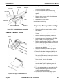
REPLACE ROLLERS -------------------------------------------------------------------------------------------------------------- 63
Replacing Transport Assembly ----------------------------------------------------------------------------------------------- 63
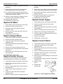
Replace DC Motor --------------------------------------------------------------------------------------------------------------- 64
Replace Stepper Motor --------------------------------------------------------------------------------------------------------- 64
Replace Stacker Sensors ------------------------------------------------------------------------------------------------------ 64
Replace Power Supply---------------------------------------------------------------------------------------------------------- 64
Replace Control Board---------------------------------------------------------------------------------------------------------- 64
APPENDIX E 926 KNIFE ASSEMBLY ---------------------------------------------------------------- 65
KNIFE SPECIFICATIONS -------------------------------------------------------------------------------------------------------- 65
TAG CUT DIMENSIONS---------------------------------------------------------------------------------------------------------- 65
FUNCTIONAL DESCRIPTION -------------------------------------------------------------------------------------------------- 65
Functional Description ---------------------------------------------------------------------------------------------------------- 65
TROUBLESHOOTING------------------------------------------------------------------------------------------------------------- 65
Evaluation of Error 760 --------------------------------------------------------------------------------------------------------- 65
VOLTAGE TESTS --------------------------------------------------------------------------------------------------------------- 66
LUBRICATION----------------------------------------------------------------------------------------------------------------------- 66
MAINTENANCE OVERVIEW---------------------------------------------------------------------------------------------------- 66
GENERAL SAFETY TIPS -------------------------------------------------------------------------------------------------------- 66
Blade Assembly Replacement ------------------------------------------------------------------------------------------------ 68
Drive Board Replacement ----------------------------------------------------------------------------------------------------- 68
Motor Replacement-------------------------------------------------------------------------------------------------------------- 68
CONNECTORS AND CABLES-------------------------------------------------------------------------------------------------- 69
iv
TC9830SM Rev. B 7/98 Confidential
List Of Tables
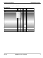
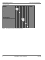
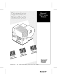
Table 1 – 1 Daughter Board DIP Switches ................................................................................................................ 4
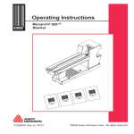
Table 1 - 2. Exterior Rear (SW2 and SW3) DIP Switch Settings .............................................................................. 5
Table 4- 1. Diagnostics Tests .................................................................................................................................. 21
Table D- 1. Stacker Control Harness........................................................................................................................ 60
Table D- 2 Jam/Full Sensor Harness....................................................................................................................... 61
Table D- 3. Extended Motor Interface Harness........................................................................................................ 61
Table D- 4. AC Power Harness. .............................................................................................................................. 61
Table D- 5. Power Supply Connector J2.................................................................................................................. 61
Table D- 6. Power Supply Connector J1.................................................................................................................. 62
Table E- 1. Knife Drive Board Voltages................................................................................................................... 66
Table E- 2. Drive Board Connector J1..................................................................................................................... 69
Table E- 3. Drive Board Connector J2..................................................................................................................... 69
Table E- 4. Knife Drive Board Connector J3............................................................................................................ 69
Table E- 5. Drive Board Connector J4 To 928 Stacker Assembly............................................................................ 69
Table E- 6. Knife Drive Board Connector J5............................................................................................................ 69
List of Figures
Figure 1 - 1. 9830 Printer (Housing removed) ........................................................................................................... 1
Figure 1 - 2. Printer Unpacking ................................................................................................................................. 3
Figure 1 - 3. SW2/SW3 DIP Switch Location ............................................................................................................. 4
Figure 2- 1. Print Assembly..................................................................................................................................... 10
Figure 2- 2. Feed Assembly .................................................................................................................................... 11
Figure 2- 3. Supply Holder Assembly ...................................................................................................................... 12
Figure 2- 4. Control Panel Assembly....................................................................................................................... 12
Figure 4- 1. Test Labels. ......................................................................................................................................... 20
Figure 4- 2. Loop Back Plug Wiring......................................................................................................................... 21
Figure 5- 1. Print Contrast Adjustment .................................................................................................................... 24
Figure 5- 2. Platen Motor Gear Adjustment ............................................................................................................. 24
Figure 5- 4. Eccentric And Locking Screw ............................................................................................................... 25
Figure 6 -1. Transformer Wiring Diagram................................................................................................................ 28
Figure 6 -2 Bridge Rectifier (Four Wires) ................................................................................................................ 28
Figure 6 -3 . Bridge Rectifier (Four Wires) .............................................................................................................. 28
Figure 6 -4.. Print Assembly.................................................................................................................................... 30
Figure 6 -5. BI-Cell Emitter Removal ...................................................................................................................... 30
Figure 6 -6. Print Assembly Plate & Printhead Module. ........................................................................................... 31
Figure 6 -7. Latch Removal..................................................................................................................................... 31
Figure 6 - 8. Bi-Cell Sensor..................................................................................................................................... 33
Figure 8 -1. Bi-Cell Sensor Adjustment ................................................................................................................... 40
Figure 8 -2. Sensor Board ....................................................................................................................................... 40
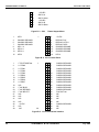
Figure B- 1. CN 1 IEEE 1284 Parallel Port ............................................................................................................. 51
Figure B- 2. CN 2 Printhead Assembly................................................................................................................ 51
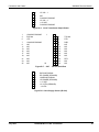
Figure B- 3. CN 3
Platen Stepper Motor............................................................................................................. 52
TC9830SM Rev. B 7/98 Confidential
v
Figure B- 4. CN 4 Control Panel............................................................................................................................. 52
Figure B- 5. CN 5 Coax/Twinax Interface................................................................................................................ 52
Figure B- 6. CN 6 Transformer Output Power ....................................................................................................... 53
Figure B- 7. CN 7 RS-232 Serial Port................................................................................................................. 53
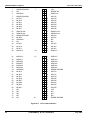
Figure B- 8. CN 8 Supply Sensor (Bi-Cell) .............................................................................................................. 53
Figure.B- 9. CN 10 Board Interface ..................................................................................................................... 54
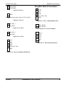
Figure B- 10. CN 11 ................................................................................................................................................. 55
Figure B- 11. CN 15 ............................................................................................................................................... 55
Figure B- 12. CN 16 ................................................................................................................................................ 55
Figure B- 13. CN 19 (to Daughter Board CN3) ....................................................................................................... 55
Figure B- 14. CN 3 To MotherBoard CN 19............................................................................................................ 55
Figure B- 15.. CN 10 Peel Motor ............................................................................................................................ 55
Figure B- 16. CN 6 On-Demand Sensor .................................................................................................................. 55
Figure C- 1. Control Board Assy. (Mother Board) ................................................................................................... 57
Figure C-2. Control Board Assy. (Daugher Board)................................................................................................... 58
Figure D- 1. Stacker Control Board. ........................................................................................................................ 62
Figure D- 2. Stacker Lubrication Points. .................................................................................................................. 62
Figure D- 3. Model 928 Stacker Assembly. ............................................................................................................. 63
Figure D- 4. Lower Transport Rollers....................................................................................................................... 63
Figure D- 5. Upper Transport Rollers. ..................................................................................................................... 63
Figure D- 6. Power Supply/Control Board................................................................................................................ 64
Figure E -1. Knife Lubrication Points....................................................................................................................... 66
Figure E -2. Location of Connectors........................................................................................................................ 66
Figure E -3. Knife Assembly.................................................................................................................................... 67
Figure E -4. Drive Board Connector Locations. ........................................................................................................ 68
vi
TC9830SM Rev. B 7/98 Confidential
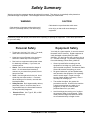
Safety Summary
Warning and caution messages appear throughout this manual. They alert you to potentially safety hazards or
potential damage to equipment. The messages and there meaning are shown below.
WARNING
CAUTION
Calls attention to practices that could cause
Calls attention to improper practices that could
result in a potentially serious, even lethal injury.
minor injury or that could cause damage to
equipment.
Familiarize yourself with proper procedures before operating or repairing the equipment. Follow these precautions
for your own safety.
Equipment Safety
Personal Safety
•
Treat every circuit as if it is “Live”. If in doubt,
check with a neon tester or voltmeter.
•
Know how to turn off power in the work area
and how to obtain help in an emergency.
•
Don’t work on equipment under power unless
it’s absolutely necessary. If you must, use
extreme caution.
•
•
Shock. Don’t under estimate the danger of
shock. 12 mA causes hand muscles to
contract, so you cannot free yourself; 24 mA
has proven fatal.
Tools. Use the right tools for the job. A tool
which slips can cause a short -- or a shock.
When working on live circuits, use tools with
insulated handles.
•
Safety Devices. Don’t bypass safety devices,
particularly fuses. If a hot wire shorts to an
ungrounded frame, the frame itself becomes
hot and potentially dangerous.
•
Electrical Fires Use Type C, BC, or ABC
extinguishers only.
Your body is a giant capacitor. It can store several
thousand volts of electricity. Digital equipment is
easily damaged or destroyed by this static
electricity. You don’t have to see a spark to ruin an
IC -- 50 volts is enough. To protect the equipment
from static damage, follow these guidelines:
•
Ground yourself before reaching into the
equipment or touching any circuit board or
other electrical component. The Monarch Static
Ground Kit contains everything you need.
•
Re-ground whenever you have walked away
and returned to the equipment. Be especially
careful around carpet. Carpet is a major
source of static buildup in the body. Even a
few steps can recharge you.
•
The smaller the object, the greater the
precautions must be. A board in the machine
is better protected than one which is not
plugged in; a chip on a board is better
protected than one in your hand.
•
Avoid touchings pins coming out of a chip or
the connector edge of circuit boards. These
metal parts have signal and data lines which
are connected directly to fragile circuits.
TC9830SM Rev. B 7/98 Confidential
vii
viii
TC9830SM Rev. B 7/98 Confidential
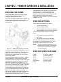
CHAPTER 1 PRINTER OVERVIEW & INSTALLATION
PRINTER FEATURES
The 9820/9830/9835 printers are on-line table-top
printers that accepts Monarch Printer Control
Language II (MPCLII) data structure.
They use a 203 dpi thermal printhead for printing. The
printhead supports both thermal transfer (heat
activated ribbon) and thermal direct (heat activated
stock) printing.
9820/9830/9835 printer operation is controlled online
via an RS-232 port, a Centronics® parallel port,
Ethernet adapter, or a CoAx/TwinAx port. Local
operation is controlled by the Control Panel and DIP
Switch settings and include Printer On/Off,
Diagnostics, On-Demand Mode , Error/Fault Condition
Indication and Clear.
PRINTER OPTIONS
These options are available for all printers:
•
TwinAx /CoAx Interface
•
Memory Expansion Board
•
Ethernet Adapter Plug #117531-01 (10BaseT)
• Ethernet Adapter Plug #117532-02 (10Base2)
The following options are available for the 9835
printer:
•
917 Keypad (for offline batch entry)
•
926 Knife
• 928 Stacker (must be used with knife)
The 9835 printer also supports 9445 emulation,
connection for an optional keyboard, and a verifier.
Service can install the above options on-site.
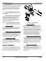
NOTE:
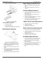
Figure 1 - 1. 9830 Printer (Housing removed)
The knife and stacker attachments can be
installed by the customer or Field Service
technicians. Ethernet Adapter Plugs are
not factory installed.
The printers have a hinged print assembly for ease in
loading and unloading the supply. The supply spool,
lower paper guide, and ribbon spool are center
justified and can be adjusted by the user to handle
various supply widths.
PRINTER SPECIFICATIONS
The printers support fanfold or roll supply. The 9835
supports tag stock to 10 mil thickness. Standard,
smudgeless, durable, and steam resistant ribbon types
are supported by all printers. Ribbon length is 600
meters and is available in core widths of 1.3”, 1.6”,
2.16”, 3.15”, and 4.13”. Used ribbon is collected on a
take-up spool by taping the ribbon leader to an empty
core. One empty core is supplied with the printer.
Height:
12.5 inches (318 mm)
Width:
12 inches (305 mm)
Depth:
13 inches (330 mm)
Weight:
29 pounds (13 kg)
Shipping Wgt:
33 pounds (15 kg)
Power:
115 VAC, 60 Hz
The 9830/9835 models offer a Service installed tear
bar, Flash ROM programming, and an optional Peel
Module for separation of supply and backing. The
Peel Module is standard on the 9830, optional for the
9835, but not available on the 9820. The 9835
supports either a Peel Module or a knife, but not both.
July 1998
TC9830SM Rev. B 7/98 Confidential
1
9820/9830/9835 Service Manual
Fuse, Inlet Module:
Printer Overview and Installation
4.0 amp, 250 V Slo-Blow®
(1 required)
Fuse, Main PCB
(5 to 35 degrees C)
Print Speed:
2D Bar Code
2.5, 4, or 6 inches/sec
Serial Bar Code
2.5 inches/sec
Max Print Image:
4 inches wide (102 mm)
16 inches long (405 mm)
Max Print
Tolerance:
+/- 0.050 inches (1.3 mm)
(side to side)
Feed Method:
On-Demand, Continuous, and
optional Peel Mode
7.0 amp, 125 V Slo-Blow
(Soldered radial leads)
Tear Bar:
9830/9835 (Service Installed)
Programming:
Flash
Communications:
Parallel Port; IEEE 1284
compliant or
Centronics Mode
Operating
Limits:
With Ribbon
40 to 95 degrees F
(4 to 35 degrees C)
Without Ribbon
40 to 104 degrees F
(4 to 40 degrees C)
STOCK SPECIFICATIONS
Ribbon:
Requirements
Thermal Transfer
1.2 inches (31mm)
4.25 inches (108mm) max
.75 inches (19mm) min
Storage
Limits:
15 to 120 degrees F
(-10 to 49 degrees C)
Stock Width:
Relative
Humidity:
5 to 90 % Non Condensing
Version 5.2 or
greater width:
Display:
Liquid Crystal Display
3 numeric digits
Stock Length:
Light Emitting Diodes
POWER green
SUPPLIES amber
PAUSED amber
Version 5.2 or
greater length:
Thermal
Printhead:
Thin Film
4.15 inches (105mm) wide
832 dots
203 dots/inch (8 dots/mm)
0.0049 inch dot width,
( 0.1245 mm), center-center
Printing
Methods:
Thermal Transfer
Thermal Direct
Supply Types:
9820 – labels only
9830 -- labels only
9835 -- labels or tags
Ribbon Types:
Roll (Non Cartridge)
Standard
Smudgeless
Durable
Steam Resistant
High Energy (9830/9835)
Ribbon Length
23,600 inches (600 m)
Ribbon Widths:
1.3 inches (33 mm)
1.6 inches (41 mm)
2.16 inches (55 mm)
3.15 inches (80 mm)
4.13 inches (105 mm)
Max Ribbon
Roll O.D.
3.6 inches (91 mm)
Ribbon Storage:
41 to 95 degrees F
2
1 inch (25mm) min
16 inches (405mm) max
12 inches (305mm) max 9820
.75 inches (19mm) min
Cut Length:
1.2 inches (31mm) min with
optional knife installed
Stock
Thickness:
0.007 inches min
(0.18mm)
0.010 inches max
(0.25mm)
Stock Roll:
Outside Diameter
9.375 inches ( 229 mm)
Inside/Core Diameter
3-4 inches (102 mm)
8100 inches (200 m) long
Stock Output:
Roll or Fanfold
Stock Type:
Die cut without Black Mark
Black Mark
Continuous
Coated Supplies
Version 5.2 or
greater stock type:
Die Cut Edge
Black Mark
Continuous
Center or Edge Aperture
TC9830SM Rev. B 7/98 Confidential
July 1998
Printer Overview and Installation
9820/9830/9835 Service Manual
UNPACKING THE PRINTER
DOCUMENTATION
1.
Clear a work area approximately four feet wide.
2.
Open shipping carton top flaps.
The following Documentation Package (TC9830DP or
TC9835DP) is provided with each printer:
3.
Remove the Documentation Package. and top
pad 000655-05.
•
quick-set Software Diskettes
•
Operator’s Handbook
In addition, these documents are available on your
Service CD-ROM as Adobe Acrobat Reader files
(.pdf):
•
Service Manual
•
Programmer’s Manual TC9800PM
TC9830SM
• TwinAx/CoAx Manual TC9800TXCX
The Operator’s Handbook (TC9830OH or TC9835OH)
can be ordered separately.
SETTING DIP SWITCHES
Figure 1 - 2. Printer Unpacking
4.
Remove scored pad 000655-02 and scored pad
000655-03 (Figure 1-2).
5.
Remove power cord from scored pad 000655-03.
NOTE:
The power cord is not included with some
models.
1. Grasp printer at base by inserting hands into
cutouts in bottom pad 000655-04. Lift printer out
of box and set on solid surface.
2. Remove poly bag 000543-01.
3. Put all packing back in the carton and set carton
aside.
4. Inspect printer for damage. Report any damage
following established procedures.
5. Open printer door and remove packing tape from
the printhead assembly.
6. Remove empty four-inch core from ribbon take-up
spool.
7. Install customer’s ribbon roll.
8. Install customer’s supply stock.
These printers have three sets of DIP switches. Two
sets are located on the back of the printer and
accessed from outside of the printer. They are
designated SW2 (Upper) and SW3 (Lower). The third
set is located on the Control Board Assembly daughter
board and is designated SW1. The printer is
delivered with the SW2 and SW3 DIP Switches set to
the defaults shown in Table 1-2. SW1 switch setting
are shown in Table 1-1.
NOTE:
DIP switches are only read at power-up.
Turn off the printer immediately after
changing DIP switch settings.
To change the DIP switch settings:
TOOLS REQUIRED:
Small Flat Blade Screwdriver
NOTE:
If software control is enabled (by setting
rear DIP switches 1 thru 3 to OFF), all rear
communications switches are ignored.
Downloaded communications settings
remain in effect until a new packet is sent
or until software control is disabled by
setting rear DIP switches 1 thru 3 to a valid
baud rate. Downloaded communications
settings remain in memory and take effect
when software control is again enabled.
DIP Switches for Version 5.2 or greater are shaded.
July 1998
TC9830SM Rev. B 7/98 Confidential
3
9820/9830/9835 Service Manual
Printer Overview and Installation
Upper DIP Switches
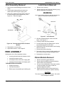
1.
Locate Upper or Lower DIP Switch block as
shown in Figure 1-3.
2.
Turn printer off and change individual DIP
switches as required. Use Table 1-1 as a guide.
3.
Daughter board SW1 settings are factory set.
However, when replacing the Control Board
Assembly, the new board must be set as shown
in Table 1-1.
Lower DIP Switches
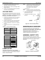
Figure 1 - 3. SW2/SW3 DIP Switch Location
Table 1 - 1. Daughter Board DIP Switches
SW1
SW2
SW3
SW4
SW5
SW6
Model #
Peel
Not used
Fox IV
Paxar CL
Memory
9820
OFF
OFF
OFF
OFF
OFF
OFF
9820 with new
ON
OFF
OFF
OFF
OFF
OFF
9830 No Peel
OFF
OFF
OFF
OFF
OFF
ON
9830 With Peel
OFF
ON
OFF
OFF
OFF
ON
Fox IV
OFF
ON
OFF
ON
OFF
ON
Paxar CL
OFF
ON
OFF
OFF
ON
ON
9835 With Peel
ON
ON
OFF
OFF
OFF
ON
9835 With Knife
ON
OFF
OFF
OFF
OFF
ON
9835 No Peel/Knife
ON
OFF
OFF
OFF
OFF
ON
sensing system
printer/applicator
FUSE REPLACEMENT
Refer to the Operator’s Handbook for fuse replacement procedures.
CONNECTING TO A HOST
For instructions on connecting the printer to a host, refer to the Operator’s Handbook.
4
TC9830SM Rev. B 7/98 Confidential
July 1998
Printer Overview and Installation
9820/9830/9835 Service Manual
Table 1 - 2. Exterior Rear (SW2 and SW3) DIP Switch Settings
Upper DIP Switches:
SELECTION
1
2
3
ON
ON
ON
OFF
OFF
OFF
OFF
ON
OFF
OFF
ON
ON
OFF
OFF
OFF
ON
OFF
ON
OFF
ON
OFF
4
5
6
7
8
DEFAULT
Baud Rate
38400
19200
9600
4800
2400
1200
Software Ctrl
Data Bits
7 Data Bits
8 Data Bits
Stop Bits
2 Stop Bits
ON Stop Bit
Parity
Even
Odd
None
Parallel Port
9600
ON
OFF
8 Data Bits
ON
OFF
1 Stop Bit
ON OFF
OFF ON
OFF OFF
None
Centronics Mode
OFF
IEEE-1284
ON
July 1998
TC9830SM Rev. B 7/98 Confidential
Centronics
5
9820/9830/9835 Service Manual
Printer Overview and Installation
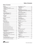
Lower DIP Switches:
SELECTION
1
2
3
4
5
6
7
8
Flow Control
XON/XOFF
ON OFF
RTS/CTS
OFF ON
DTR
OFF OFF
Diagnostics
Normal Run Mode
OFF
Diagnostics Mode
ON
Verifier
OFF
No Verifier
ON
Verifier Installed
Supply Type/ Sensing
Die Cut or Edge Aperture (edge sensor)
OFF OFF
Black Mark (center sensor)
OFF ON
Continuous (no sensor)
ON OFF
ON ON
Center Aperture (center sensor)
Ribbon
Transfer
OFF
Direct
ON
Feed Mode
Continuous
OFF
On-Demand
ON
NOTE:
6
DEFAULT
DTR
Normal
No Verifier
Die Cut
Transfer
Continuous
DIP Switches for Version 5.2 or greater are shaded.
TC9830SM Rev. B 7/98 Confidential
July 1998
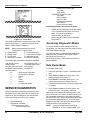
CHAPTER 2 FUNCTIONAL DESCRIPTION
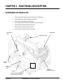
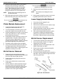
OVERVIEW OF MODULES
•
Power Transformer Assembly (Power Supply and Distribution)
•
Control Board Assy. (Data Handling and Control)
•
Peel Module (Supply/Backing Separation)
•
Print Assembly (Thermal Control and Motion Synchronization)
•
Feed Assembly (Supply Alignment/Tension)
•
Supply Holder Assembly (Supply Guide)
•
Control Panel Assembly (Operator Interface)
Print Assembly
Control Board
Assy.
Supply Holder Assy.
AC Inlet
Module
Power
Transformer
Assy.
Peel Module
(inside door of 9830)
Rectifier
Control Panel Assembly (Mounted
to printer housing- not shown)
July 1998
TC9830SM Rev. B 7/98 Confidential
9820/9830/9835 Service Manual
Functional Description
Power Transformer Assembly
The power transformer assembly is located beneath
the printer’s back cover and includes three
components:
Inlet Power Module
The power module is attached to the printer’s rear
panel just in front of the Control Board Assy. Its face
plate partially extends through the rear panel to allow
users access to the power receptacle, fuse box/power
selector and the on/off switch. It has wire attachments
to ground the Power Transformer.
This module includes the following components:
•
International line cord receptacle
• 4.0 Amp, 250VAC Slo-Blow fuse
Line voltage enters at the cord receptacle and passes
through a slow-blow fuse. The slow-blow fuse protects
the system from damage by power surges. Line
ground is provided to the printer via a ground harness
connected to the bottom frame.
CONTROL BOARD
ASSEMBLY
The Control Board Assembly is located on the back
side of the printer frame wall beneath the printer’s
back cover. It consists of a mother board and a
daughter board. The two boards are replaced as a
single assembly. The board assembly is mounted on
six quick-release aluminum standoffs. Three of the
standoffs are threaded for retainer screws.
The board has three connectors (serial port, parallel
port, and bar code verifier), the print contrast control,
and three DIP switch assemblies. Two are mounted
on the long vertical side allowing for external access.
The third DIP switch is located on the daughter board.
There is a connector across the top of the board and a
hall effect sensor at the top right corner of the board to
sense a “Head Open” condition. Eight additional
connectors accept cabling to other printer assemblies.
The daughter board has a connector for cabling to the
mother board, and two connectors for functional
expansion.
Power Transformer
The power transformer is available in three voltages:
110V, 115V, or 220V. It is attached to the frame base
just below the print module. The transformer gets AC
line voltage from the inlet power module and converts
it to two AC output voltages. The first is sent directly
to the Control Board Assembly for futher conditioning.
The second output is sent to the bridge rectifier for
additional conversion.
The power transformer assembly outputs the required
AC and DC voltages for operation of the printer and
sends both voltages directly to the Control Board
Assy. Further conversion and/or distribution is made
by the Control Board Assy. Major functions of the
power transformer include providing power to the Inlet
Power Module, Power Transformer, and to the Bridge
Rectifier.
Bridge Rectifier
The bridge rectifier is a 1” x 1” assembly fastened to
the printer frame base left of the power transformer. It
has wire attachments to ground, the power
transformer, and the Control Board Assy.
The bridge rectifier accepts the AC from the power
transformer and converts it to DC. This voltage is
then supplied to the Control Board Assembly for
further conversion.
8
Functional Description
The Control Board Assy. controls all electrical
requirements for the printer and contains interfaces for
controlling all printer functions, including Ribbon
Supply and Take-up motors, Stepper Motor, Peel
motor, Knife motor, and the Printhead. A single
microcomputing unit consisting of a 32-bit RISC
processor, 256K OTPROM (16 bits), and 256K (16
bits) of Dynamic RAM (DRAM) controls the interfaces.
Major functions of the Control Board Assy. are:
•
Power Conversion
•
Memory
•
Printer Control
•
Operator Panel Control
•
Communications
•
Contrast Control
•
Hardware Power-up Settings (DIP Switches)
•
Peel Motor Control
•
On-Demand Sensor Interface
•
Knife Motor
TC9830SM Rev. B 7/98 Confidential
July 1998
Functional Description
9820/9830/9835 Service Manual
Power Conversion
Power conversion interface receives AC and DC
voltage from the Power Transformer assembly.
35VAC is converted to +12VDC and -12VDC, while
the 40VDC input is converted to +25VDC and +5VDC.
Memory
Control Board Assebmly contains three types of
memory: Flash, DRAM and SRAM.
Flash Memory
Flash memory contains the necessary BOOT code
and Operating System functions for I/O routines used
for communications, the application program, fonts,
formats, and the Kernel/Library functions.
DRAM Memory
DRAM is used for variable storage, buffers, and image
memory. The base memory configuration for the
printer is 256K (16 bits).
SRAM Memory
SRAM (32K of non-volatile static RAM ) is used to
store system parameters and machine totals. All
relevant information is automatically stored in the
SRAM when the printer is turned off.
Printer Control
Control Board Assembly controls all printer functions.
It use a high performance, 32-bit, RISC based,
integrated microcontroller. The microcontroller
performs imaging and provides interfaces to printer
control operations. Major functions of the board are:
Data Handling
During operation, communication with both the RS232 port and the High Speed parallel port is
maintained. MPCL data received is transferred to
Dynamic RAM (DRAM)
Printhead Thermal Control
Printhead thermal control operation is a dynamic
closed loop servo circuit that adjusts the on/off duty
cycle in response to a continuously monitored
Printhead operating temperature and resistance.
Print Imaging
The Thermal Printhead Interface is controlled by the
microcontroller. Page image data is transferred from
Dynamic RAM to the thermal printhead as a serial
data stream.
July 1998
Motion Control
Motion control sub-system controls four DC motors.
Two DC motors drive the Ribbon control, a stepper
motor controls the platen drive, and a fourth motor
drives the Peel Module.
Platen Drive Interface
Control Board Assembly controls the platen drive
motor’s torque, speed and direction through the use of
four phased 25Vdc output signals. Motor torque and
direction is controlled by changing the sequence and
pattern of the four signals. Motor speed is controlled
by increasing or decreasing the speed of the digital
pulse that make up the four phased signals.
Ribbon Drive Interface
Electronically controlled DC motors drive the ribbon
over the printhead. The motors, and associated
control software, control the tension of the ribbon web
as the ribbon spools from the supply side to the takeup side. A speed-detection method using BEMF
(Back Electromagnetic Motor Force) provides
accurate ribbon tension control.
Analog to Digital Conversion
An ML2255 A/D converter, in conjunction with the
microcontroller, monitors system functions. The A/D
converter combines an 8-Bit A/D converter, 8-channel
analog multiplexer, and a microcontroller-compatible,
8-bit parallel interface and control logic. The A/D
converter monitors various system functions and
provides information to the printers firmware to control
the supply motion, print quality, etc.
Supply Detection & Tracking System
See Chapter 8, “Supply Sensing Systems” for more
information.
Operator Control Panel
Printer Control Board uses a Peripheral Interface Unit
(PIU) to control the operator control panel interface
comprised of a three digit display, three push-button
keys and three LEDs.
An optional 917 Keypad is available for the 9835
printer (offline batch entry).
Communications
RS-232 interface and the Centronics/IEEE 1284
compliant parallel interfaces are mounted on the
Control Board Assy. Both are located on the left edge
of the board and accessed by the user at the rear of
the printer near the supply roll.
TC9830SM Rev. B 7/98 Confidential
9
9820/9830/9835 Service Manual
Functional Description
RS-232 interface
This interface allows connection to devices capable of
RS-232 communications. The interface is incorporated
in the microcontroller and has DIP switches to set
communications parameters. The DIP switches can
be set manually by the user or through software
control.
Centronics IEEE-1284 Parallel Interface
This interface accommodates high data rates, up to
2M Bits/Second.
IEEE 1284 Bi-Directional Parallel Interface
An IEEE 1284 High Speed Bi-directional Parallel
interface provides parallel communications. The
microcontroller directly controls the port. The
interface allows compatibility with the Centronics
interface as well as allowing for High Speed Bidirectional communications.
NOTE:
Third party LAN devices are connected
through the parallel interface to allow the
printer to interface different LAN networks.
Contrast Control
A manual contrast control, located at the edge of the
Control Board Assy., extends out of the rear cover. It
is used for fine adjustments to the print contrast
values.
Hardware Power-up Settings (DIPS)
Two 8-switch DIP switches, located on the back panel
of the printer above the contrast adjustment, control
the default power-up configuration of the printer.
Settings include the serial port settings, diagnostics,
ribbon setup, printer mode and supply type.
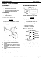
Peel Module Assembly
The peel module separates the supply from the
backing paper. It consists of an on-demand sensor,
rollers, and a 12Vdc motor drive. Dip SW1 (switch 2)
located on the daughter board enables and disables
the peel function.
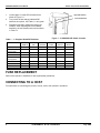
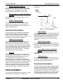
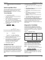
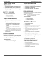
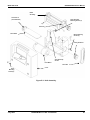
Figure 2- 1. Print Assembly
Thermal Printhead
The printhead is located at the bottom front of the
module. It is held in place by a plastic carrier which
acts as an interlock to a formed metal bracket. The
bracket is center-mounted and pivots to ensure an
even pressure on the supply. The printhead bracket
has two alignment loops which slip over the platen
roller to assure dot row to platen roller alignment. The
printhead mount also has two spring loaded
adjustment knobs to adjust printhead pressure for
wide or narrow supplies. A 30 pin ribbon cable
connects the printhead to the Control Board Assy
Ribbon Supply & Take-up Spools
The ribbon supply and ribbon take-up spools are
located on the supply side of the module. Each spool
shaft extends through the module wall and connects to
its own DC drive motor. The spools are designed to
handle a detented ribbon core so when ribbons of
various widths are installed they maintain center
justification.
Ribbon Transfer Rollers
PRINT ASSEMBLY
This Print Module is a plastic casting located inside
the printer’s hood. It is attached to the mid frame by
two bearing blocks which capture studs on the module
back plate. Components of the Print Module are:
10
Two ribbon transfer rollers are located on the supply
side of the module. The rollers are ribbed and
attached to metal shafts by retainer screws. One sits
at the very front of the module wall above the
printhead while the other is positioned just above the
supply deflector.
TC9830SM Rev. B 7/98 Confidential
July 1998
Functional Description
9820/9830/9835 Service Manual
Ribbon Spool Drive Motors
wo DC ribbon drive motors are mounded to the back
of the module wall. Each motor drives a ribbon spool.
The motors are connected directly to the Control
Board Assembly via separate two-wire harness.
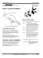
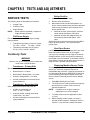
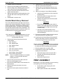
fastened to the printer base. Components of the feed
module are:
Supply Deflector and Bi-Cell Emitter
(IR LED)
Bearing
Blocks
See Chapter 8, “Supply Sensing Systems” for more
information.
Spring
Ribbon Transfer Rollers
The two ribbon transfer rollers allow ribbon tension
adjustments. Each roller has an eccentric which
allows slight skew adjustments to each, which in turn
affects the ribbon tension.
Latch
Figure 2- 2. Feed Assembly
Functional Description
The print module, performs ribbon drive operations,
provides mechanical ribbon tension adjustments,
performs print functions, helps maintain supplies
tracking, and houses half of the sensor assembly. It is
controlled by the Control Board Assembly.
Ribbon Drive Operation
The ribbon drive operation is made up of two ribbon
spools, two 25Vdc drive motors, and two ribbon
transfer rollers. It is controlled by the Control Board
Assy. Each drive motor sends continuous information
to the Control Board Assy. where it is used to evaluate
ribbon conditions, maintain optimum ribbon tension,
and sense the end of ribbon condition. This system
eliminates the need for ribbon sensors.
Printing
The printhead has a line array of 832 dot elements
sized to produce 203 dots per inch. Printing occurs by
sending image data to the printhead one line at a
time. Each time a line of data is received,
corresponding dots on the printhead are heated to
create an image line on the stock. Successive image
lines generated across moving stock make up the total
image. The Control Board Assy. controls all image
data sent to the printhead, and regulates the energy
level of the printhead. Energy levels are raised and
lowered to create darker or lighter print respectively.
FEED ASSEMBLY
The feed module components are mounted on a metal
frame positioned beneath the Print module and
July 1998
Platen Module
The platen rollers are on top of the feed module frame
just beneath the printhead. It is held in place by two
bearing blocks latched on the frame sides. The inner
side of the platen roller shaft extends through the
inside wall of the feed module where a drive gear is
attached.
24VDC Stepper Motor
The stepper motor is located behind the mid-frame of
the printer. Its drive shaft and gear extends through to
the space between the printer mid-frame and the feed
module frame.
Lower Supply Guide and Bi-Cell
Sensor
See Chapter 8, “Supply Sensing Systems” for more
information.
Printhead Latch
The printhead latch is spring loaded and mounted on
the outside of the feed module frame; within the latch
fascia. It locks the printhead in position.
Functional Description
The feed module transports supply through the printer
and across the printhead. It also maintaining proper
alignment, tension, and speed. This is accomplished
by sensing the stock position while securing the
printhead down onto the platen roller. Major functions
are supply feeding and supply sensing. See Chapter
8, “Supply Sensing Systems” for more information.
TC9830SM Rev. B 7/98 Confidential
11
9820/9830/9835 Service Manual
Functional Description
Printhead Locking
Printhead release knob is used to release the print
module from its open position.
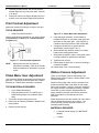
SUPPLY HOLDER ASSEMBLY
Inner Guide
Outer Guide
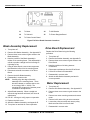
Figure 2- 4. Control Panel Assembly
Functional Description
LEDs
The three LEDs indicate general printer
status and activity.
LCD
The three-character LCD identifies
specific printer conditions through the
use of numeric codes. These codes are
listed and described in Appendix A.
Feed
In Normal mode, advances a label from
the printer. In Offline mode or Online
Diagnostic mode, prints a test label.
Pause
Stops the current batch from printing.
Printing resumes when Pause is
pressed a second time.
Clear
Cancels the current batch from being
printed if pressed for only a moment.
Cancels all batches associated with the
current format if pressed and held for
two seconds. Cancels some error
codes that appear on the LCD.
Figure 2- 3. Supply Holder Assembly
Functional Description
The supply holder module holds the supply roll in a
center-justified position to ensure optimum supply
tracking. The guides are gently pushed inward until
they center the roll and back off to the next detent
position when released.
The front guide pivots down for supply
loading/unloading. When loading fanfold supply, the
stack is placed behind the printer or under the table
and fed through the supply holder guides.
CONTROL PANEL ASSEMBLY
The Control Panel Assembly is mounted on the front
of the printer. The associated electronic components
are mounted on a circuit board behind the panel
fascia. A ground wire connects the board to the
chassis ground and a single wire harness connects it
to the Control Board Assy.
12
Feed + Pause
In Normal mode, prints a test
label.
Feed + Clear
In Diagnostics mode, places the
printer in data dump mode. See
Chapter 4, “Diagnostics” for
more information.
TC9830SM Rev. B 7/98 Confidential
July 1998
CHAPTER 3 TROUBLESHOOTING
This chapter contains suggestions for diagnostic and repair actions.
PRELIMINARY CHECK
The following checks should be made before going further:
1.
Are the DIP switches set properly to match communication values and existing supply?
See Chapter 1 for DIP Switch settings and procedures.
2.
Ensure that the proper fuse has been installed. See the Operator’s Handbook.
3.
Inspect printhead to ensure it is locked in place.
4.
Ensure stock and ribbon are properly loaded. Refer to the Operator’s Handbook for printer loading instructions.
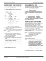
ANALYZING FAILURE DURING POWER UP
Each time the printer is turned on, it runs Power-up Diagnostics. These Level 0 Diagnostic Tests are described in
detail in Chapter 4. If any of the first eight tests result in a fault condition, a three digit status code is indicated on the
Control Panel LCD. As shown in Figure 4-2, if any of the following status codes are indicated, the printer will stop
operating, and remain in a “hold mode” until CLEAR is pressed:
909
Memory Failure
911
Virgin Reset
NOTE:
765
Printhead Test Failure
These error codes only appear during a power-up test sequence. If a “765” status code is indicated during
the power on tests, the printer is still operational but may not be able to print all of the commanded label
images.
The Control Panel is tested during the power-up tests by blanking the three digit LCD display momentarily. This is the
final Level 0 test, and would be noticed only if a “765” status code were previously indicated.
EVALUATION OF A 616 ERROR (DOT SHIFTING FAILED)
This error occurs if at least one dot element is non-functional. Shifting the image pattern will not work. You must
replace the printhead.
EVALUATION OF A 704 ERROR (OUT OF SUPPLY)
This error occurs when the sensor is not sensing the supply. This can happen if there is a problem with the supply or
with the sensor. Perform the following procedure:
1.
Verify stock is loaded and properly aligned in the supply guide.
2.
Verify that DIP switches and online settings are set for proper supply type.
3.
Check Bi-cell alignment using gray scale, and check operation using diagnostic procedures (be sure to check
the harness). See Sensor Tests and Bi-Cell Sensor Adjustment, in Chapter 8, for instructions.
4.
Verify Emitter is operational (including the harness) by using an infrared detector probe.
July 1998
TC9830SM Rev. B 7/98 Confidential
13
9820/9830/9835 Service Manual
Troubleshooting
EVALUATION OF A 754 ERROR (OUT OF RIBBON)
This error occurs whenever the ribbon stops turning. This can happen if the motors are not working, the stock is
binding, the platen is sticky, or if any condition is present that prevents ribbon rotation. Perform the following
procedure:
1.
Verify Ribbon Motors are turning. If they are not, check connectors to the Control Board Assy. and the
connections to the motors.
2.
Verify Platen Motor is feeding. If is is not, check the connections.
EVALUATION OF A 755 ERROR (PRINTHEAD OPEN)
This error occurs if the printhead is not functioning properly. Perform the following procedure:
1.
Ensure the printhead is properly latched.
2.
Verify that the magnet is present and inserted properly.
3.
Verify that sensor is functioning properly.
EVALUATION OF A 765 ERROR (PRINTHEAD FAILURE)
This error occurs if a dot is out of specification. This error can occur even if print quality is not visibly affected.
Operation can be continued until the problem is corrected. Perform the following procedure:
1.
Check connections to the printhead.
2.
Check the printhead harness.
3.
Check the printhead itself and replace if necessary.
EVALUATION OF THE CONTROL BOARD ASSY.
The following status codes indicate the Control Board Assembly has a fault.
900
RAM Test Failure
905
Illegal Interrupt
901
ROM/EPROM Test Failure
906
Power Failure
902
Timer Failure
907
No Application Memory
903
Interrupt Test Failure
908
NVRAM Checksum Failure
904
No Kernel Memory
910
Warm Restart
1.
To determine if this fault is permanent or temporary, turn the printer off, wait 15 seconds then turn the printer on
again. If any of these status codes are repeated, turn off the printer and replace the Control Board Assy.
2.
Print a test label. See Test Label (Level 1), in Chapter 4, for instructions on printing a test label.
3.
Place the printer in Data Dump mode and send data to the printer.
EVALUATION OF COMMUNICATIONS
If the printer functions properly off-line, examine communications. There are two communication paths for the
printer. The RS-232 serial path uses a 25 position connector. The IEEE-1284 parallel path consists of an external
36 position connector, CN1, and an internal 40 position connector, CN5, that is used to support the Coax/TwinAx
Interface. CN1 also supports an external Ethernet adapter.
14
TC9830SM Rev. B 7/98 Confidential
July 1998
Troubleshooting
9820/9830/9835 Service Manual
The external Coax/TwinAx Interface is a 15 position connector into which is plugged either a Coax adapter cable or a
TwinAx adapter cable. (All electronic activity for the serial port is limited to the Control Board Assembly. All
electronic activity through CN1 is limited to the Control Board Assy.) There is a small circuit board mounted on the
inside rear printer wall that interconnects the 15 position external connector with the internal CN5. Both CN1 and
CN5 share common PCB electronics.
1. Make sure the printer is plugged in and connected to a host with the proper cables. See Connecting to a Host,
in Chapter 1.
2. Compare host communication values to values reported on the test label. See Test Label (Level 1), in Chapter
4, for instructions on printing a test label.
3. Check printer ports using SENDFILE to send an ENQ.
GENERAL TROUBLESHOOTING SUGGESTIONS
There are a number of printer self-reporting fault detection/fault isolation avenues built into the 9820/9830/9835
printers. Three digit status codes, detailed in Appendix A, all help to pinpoint the problem. In addition, the printer
provides status information in the two test labels, in the SENDFILE service diagnostics tests, and in information
labels printed in response to a FEED command following a status code between 571 through 619.
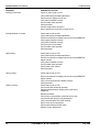
PROBLEM
SUGGESTED ACTION
Printer does not print test labels
Check for status code on LCD.
Verify stock is installed correctly.
Verify ribbon is installed correctly.
Verify printer voltage measurements.
Verify printhead is installed correctly.
Verify printhead harness connection is on PCB.
Verify DIP switch settings.
Confirm supply feed operation.
Confirm ribbon feed operation.
Perform sensor display service test using SENDFILE.
Perform test label immediate command.
Replace control panel.
Replace printhead.
Replace Control Board Assy.
Printer only prints test labels
Check for status code on LCD.
Verify comm DIP switch settings.
Perform serial /parallel comm test.
Perform data transfer immediate commands.
Transfer format using Windows Terminal.
July 1998
TC9830SM Rev. B 7/98 Confidential
15
9820/9830/9835 Service Manual
Troubleshooting
PROBLEM
SUGGESTED ACTION
Partially printed data
Check for status code on LCD.
Verify wide/narrow printhead adjustment.
Perform sensor display service test.
Verify ribbon installed correctly.
Confirm ribbon feed operation.
Clean printhead.
Confirm supply sensor operation.
Send a packet you know has no syntax errors.
Printing shadows or smears
Check status code on LCD.
Verify wide/narrow printhead adjustment.
Perform contrast sensor display service test using SENDFILE.
Verify supply installed correctly.
Verify ribbon installed correctly.
Confirm stock feed operation.
Confirm ribbon feed operation.
Clean printhead.
Light printing
Check status code on LCD.
Verify wide/narrow printhead adjustment.
Perform contrast sensor display service test using SENDFILE.
Adjust contrast.
Verify ribbon installed correctly.
Confirm ribbon feed operation.
Check platen roller surface.
Clean printhead.
Heavy printing
Check status code on LCD.
Perform contrast sensor display service test using SENDFILE.
Adjust contrast.
Verify correct stock/ribbon installed correctly.
Clean printhead.
Check status code on LCD.
Confirm test label printhead operation.
Perform printhead sensor display service test using
SENDFILE.
Replace printhead.
Confirm fault via immediate command service test.
Confirm test label printer config parameters.
Verify communication DIP switch settings.
Send a corrected format packet.
Perform terminal data transfer tests.
Replace Control Board Assy.
Voids in printing
16
TC9830SM Rev. B 7/98 Confidential
July 1998
CHAPTER 4 DIAGNOSTICS
If you have any problems using SENDFILE, refer to the Sendfile Manual on your Service CD-ROM.
The following diagnostics are resident in the
9820/9830/9835 printer’s firmware ROM:
•
Power-Up Self-Test
•
Test Label
•
Service Diagnostics (Level 1)
Data Dump Mode
Diagnostics Test Mode
Off-line Diagnostics Tests
Loopback Test (Level 2)
Parallel Port Test (Level 3)
•
Different versions of software installed.
•
Clearing memory with the “Reset NVRAM”
function in service diagnostics.
•
POWER-UP SELF-TEST
When the printer is turned on, a test sequence is
initiated. The diagnostics routine initializes the
Control Board Assembly and evaluates the Printhead.
The test sequence is:
•
Non-Volatile RAM Byte Test
•
Version String Mismatch
• Printhead Dot Resistance
A failure in any of the test sequences results in the
display of an error code on the 3 digit Control Panel
Display.
An error during the printhead dot test indicates that
bar code scan quality may be compromised.
However, such a failure may not be evident in text
printing.
Memory corrupt due to a hardware/software
error.
If the restart flag was set during these diagnostic tests,
the software re-allocates all available memory as
blocks of working storage. Then the routine performs
an integrity check on the working storage to verify that
it is accessible.
When the version string mismatch test passes, the
firmware begins the printhead dot resistance test.
Printhead Dot Resistance
The printhead resistance routine is a hardware test of
all 832 individual dots for correct resistance value. If
the test passes, the printer switches to online ready
mode. If the test detects any dots that are open or
have high resistance (>852 Ohms), error #765
appears on the LCD. Failure does not halt printer
operations.
TEST LABEL (LEVEL 1)
Test Label can be performed in Normal or Diagnostics
Test mode. When the printer finishes printing the two
test labels, it returns to the ready state.
MATERIALS REQUIRED:
NV RAM ByteTest
Installed supply stock, at least 1” wide X 2” long.
The Non-Volatile RAM test checks the first two bytes
of NVRAM. If the test passes, the next test begins. If
the test fails, error #909 appears on the display.
1.
Two test labels print (See Figure 4-3). If the test
fails, an error appears on the LCD. Press Clear
to reset the printer.
Version String Mismatch
The version string test compares the software version
in ROM to the version in RAM. If the versions match,
the current software is in RAM and the software clears
storage RAM. Then the software clears the working
storage routine. If the versions in ROM and RAM do
not match, error #911 appears on the LCD.
If the printer is in Normal Mode, press Feed +
Pause at the same time. If the printer is in
Diagnostics Test mode, press Feed.
2.
Examine the test labels for smearing, image
washout, print uniformity, contrast, missing dots,
or out of specification readings.
System Restart Condition
The three conditions that cause a system
restart are:
July 1998
TC9830SM Rev. B 7/98 Confidential
19
9820/9830/9835 Service Manual
Diagnostics
Parallel Port Timeout Test
Test Label
Virgin Reset
SENDFILE Diagnostic Tests
Test Label
Sensor Display
Service Totals
Immediate Commands
Job Request
Printer Interactive Mode
Supporting Hardware Accessories Required:
Figure 4- 1. Test Labels
•
SENDFILE and Flashloader requires a laptop
or PC connected to the printer via a serial
cable. PC should be capable of
communicating at 38.4 baud.
•
Serial Loop Back Test requires Loop Back
Plug #114271.
The first test label prints firmware version and current
printer configuration in I packet format (refer to the
printer’s Packet Reference Manual ).
Accessing Diagnostic Modes
NOTE:
To use the different modes available in Service
Diagnostics, you must have lower DIP switch 3 turned
on and the display reads 000.
A
B
C
D
Some reported settings may not be
configurable on a given printer:
System Setup
Supply Setup
Print Control
Monetary Formatting
E
F
G
M
Control Characters
Serial Comm Settings
Backfeed Control
Memory Allocation
The second label prints basic diagnostic information:
Total Inches Printed
Current Inches
+40 VDC Value (s/b 30-47)
Dot Resist (s/b 832 Ohms)
Installed Options:
M
R
V
P
C
S
X
No of Bad Dots (s/b < 3)
Total RAM (Max 512K)
DIP Settings
Contrast Pot
256K memory expansion
RS-232 option (Keypad)
Verifer
Peel
Cutter
Stacker
V5.2 sensing system
SERVICE DIAGNOSTICS
Service Diagnostics is initiated by setting the Lower
DIP switch 3 to the ON position before powering up.
At power-up, 000 is displayed on the control panel.
Two Service Diagnostic modes are available:
20
•
Data Dump Mode
•
Diagnostics Test Mode
Off-line Diagnostics Tests
Serial Loop Back Test
From the 000 display, press Feed and Clear at the
same time until you see 001 (data dump mode),
002 (serial loop back test), or
003 (parallel port test). Each mode is activated by
pressing Pause.
Data Dump Mode
To use data dump mode:
1. Set lower DIP switch 3 to ON. The display reads
000.
2. Press Feed and Clear at the same time. The
display changes to 001 (Mode 1).
3. Press Pause to enter data dump mode. Two
blank labels feed and the display reads 111.
4. Download the data stream you want to dump (print
on a label).
5. Press Feed and Clear at the same time to exit
data dump mode. The display reads 000.
Data dump mode captures all data being sent to the
printer and holds it in a buffer. No data is acted upon
(ex: Immediate commands or Job request packets).
Once the buffer is full, a label automatically prints with
the downloaded data printed on it. You must press
Feed to print a label if the amount of data sent does
not fill the buffer to the required level.
NOTE:
If you are sending data down through
SENDFILE, be sure to disable ENQ. This
TC9830SM Rev. B 7/98 Confidential
July 1998
Diagnostics
9820/9830/9835 Service Manual
applies only when you are in Data Dump
mode.
Serial Loop Back Test
This test evaluates serial port circuits on the Control
Board Assembly (nothing external to the Control
Board), so communication setting DIPs 1 through 10
do not affect this test.
TOOLS REQUIRED:
•
Loop Back Plug 114271
1.
Turn printer off and disconnect host serial port
connector from CN 7.
2.
Install Loop Back Plug into RS-232 Serial Port
CN 7. See Figure 4-4 for plug wiring.
3.
Turn the printer on and go into Diagnostics Test
Mode 2 (002). This is accomplished by pressing
the Feed or Clear key from Mode 1 (001).
4.
Press PAUSE.
Jumper Pins
2-3
Signal
To change the parallel port timeout:
1. Set lower DIP switch 3 to ON. The display reads
000.
2. Press Feed and Clear at the same time until the
display reads 003 (Mode 3).
3. Press Pause to enter the parallel port timeout
mode.
4. Press Clear to increase the timeout and press
Feed to decrease the timeout.
The display changes to show the amount of the
timeout.
5. Press Feed and Clear at the same time to exit
data dump mode. The display reads 000.
The amount of data the application processes from
the communication driver is 128 bytes at a time. Flow
control is now activated when there is 512 bytes left
available in the buffer and flow control is now
deactivated when there is 1024 bytes available in the
receive queue.
Diagnostics Test Mode
TXD-RXD
There are two types of Diagnostics Tests; those
performed off-line by pressing some keys and those
performed using SENDFILE. Table 4-1 lists the tests
and procedures that can be performed in Diagnostics
Test mode.
4-6
RTS/DSR
5-20
DTR-CTS
Table 4- 1. Diagnostics Tests
Figure 4- 2. Loop Back Plug Wiring
DIAGNOSTICS
TEST
OFF-LINE
ONLINE
KEYS
5.
The test runs automatically once initiated, and
takes approximately two seconds.
Loop Back Test
off-line
Pause
6.
If the test passes, 222 is displayed. If the test
fails (Loopback Plug not installed, installed
incorrectly, or bad Control Board Assy.
components) error #499 is displayed.
Virgin Printer Reset
off-line
Feed+Clear+
Pause
7.
Press Feed and Clear to exit.
Parallel Port Test
The parallel port timeout test can be used with version
3.1 or greater firmware. When the parallel port is in
flow control, the printer continues to accept data one
character at a time until the entire receive buffer is
full. The rate that data is accepted can be set through
this diagnostic mode. The default is one character per
every 10 seconds. This value prints out on the test
label.
July 1998
Performing a Virgin Printer Reset
A Virgin Printer Reset sets the printer to its original
factory settings and erases all data in RAM. To
initiate a virgin reset, hold down Feed + Clear +
Pause for approximately two seconds, and release.
NOTE:
Using “Virgin Reset Command“ in
SENDFILE requires the Service Password.
Printing a Test Label
Print a test label by pressing the Feed while in Data
Dump mode or Diagnostics Test mode. For more
information on printing a test label, see “Test Label,”
earlier in this chapter.
TC9830SM Rev. B 7/98 Confidential
21
9820/9830/9835 Service Manual
22
Diagnostics
TC9830SM Rev. B 7/98 Confidential
July 1998
CHAPTER 5 TESTS AND ADJUSTMENTS
Bridge Rectifier
SERVICE TESTS
1.
Set Ohm meter to 2000K scale.
The following tests are described in this section:
2.
Remove wires from device.
3.
Black lead on Red wire terminal (labeled + on
device, at the notched corner) and leave attached
while moving red lead to other terminals of the
device should yield:
•
Voltage Tests
•
Continuity Tests
•
Supply Quality
NOTE:
•
Sensor tests are described in Chapter 8,
“Supply Sensing Systems.”
Red lead on either yellow wire 90° from that
corner should read approx. 500 ohms.
•
CN6 Power Supply
Pin numbers are read from left to right including
empty positions.
•
Transformer secondary non-rect AC output
Pin 1 & 3 = 15VAC
Pin 3& 4 = 15VAC
•
Transformer secondary rect DC output
Pin 5(+) & Pin 6 (Grnd) = 40VDC
Continuity Tests
WARNING
Failure to turn off and unplug printer for these test
could result in electrical shock.
Transformer - Primary Side
Should be tested at AC Inlet under the boot.
•
Black & Brown = 0-2 ohms
•
Black-White & Brown-White = 0-2 ohms
•
Orange & Orange-White = 0-2 ohms
•
All other combinations must read infinite
(open) resistance.
Transformer - Secondary Side
Red lead on black wire (diagonal from red
wire terminal) should read approx. 1000
ohms.
Switch Red lead to red wire terminal and move Black
lead to all other positions. The result should be
infinite ohms.
Head Open Sensor
Hall Effect Sensor (HALL1) is located at the top of the
board and must be within 6 mm of the magnet.
Top leg of chip (closest to the top edge of the board)
changes between +5VDC and ground in response to
the magnet in the Print Module. It should be at 0VDC
(with respect to frame ground) when head is closed. If
magnet is bent, operation may be affected.
Displaying Machine/Service Totals
This test is performed online using SENDFILE. Only
the Service Totals test sequence requires an
intermediate step to access. It requires the operator to
run Diagnostics (D) from the SENDFILE Format Page
screen, resulting in the Sensor Display format, and
then run Service Totals (S) from the Sensor Display
screen.
1.
Press M for Modify Service Totals.
2.
The initial Service Totals format has a temporary
prompt box in the center of the screen that
requests a password.
Ohm reading must be taken with power off.
•
At CN6, all combinations of
Pins 1, 3, & 4 = 0-1 ohms
NOTE:
•
At bridge rectifier, reading across both
Yellow wires = 0-1 ohms
3.
•
To modify totals, enter the applicable number
(1,2,3,4 ).
All other combinations must read infinite
(open) resistance
4.
Before clearing a totals number, the routine
prompts another response. Pressing Y causes a
reset to 0. Any other entry results in an abort.
July 1998
If a password is not given, totals are
displayed but can not be changed.
TC9830SM Rev. B 7/98 Confidential
23
9820/9830/9835Service Manual
Confidential
5.
Following a totals number, the routine prompts
another response. Any entry other than Y results
in an abort.
6.
Press D to return to the Sensor Display screen or
press L to exit the Sensor Display test sequence.
Tests and Adjustments
Print Contrast Adjustment
Adjust print contrast if printing is too light or too dark.
TOOLS REQUIRED:
•
Small Flat-head Screwdriver
Using a small flat-head screwdriver, turn print contrast
knob(clockwise for darker print--counterclockwise
for lighter print).
Figure 5- 2. Platen Motor Gear Adjustment
4. Using the paper shimstock, check clearance
between the bearer on the platen motor gear and
the bearer on the platen gear. (See Figure 5-2)
Clearance should be between 0.006” and 0.008”.
5. If clearance is less than or greater than the
specification, perform steps 7 thru 11.
6. With printhead fully latched, loosen four Phillips
head screws holding platen motor.
7. With paper shimstock in place, move platen motor
housing to adjust for specification clearance.
Figure 5- 1. Print Contrast Adjustment
NOTE:
Adjustments may also be made via
immediate commands. Refer to the Packet
Reference Manual for information on proper
syntax.
8. Tighten all four screws.
9. Rotate platen by hand 360° to check for binding or
excessive backlash.
10. Repeat steps 7 thru 10 as necessary.
Ribbon Tension Adjustment
Platen Motor Gear Adjustment
This procedure adjusts the backlash in the platen drive
gear train. It should be performed each time a Platen
Assembly or a Platen Motor Assembly is replaced.
TOOLS/MATERIALS REQUIRED:
•
6-inch Phillips Screwdriver
•
Paper Shimstock (0.006” to 0.008” thick) or
Label Backing Paper Liner (folded 3 layers
thick)
1. Turn printer off and unplug power cord.
2. Raise cover and ensure printhead is latched in the
down position.
3. Remove printer housing.
24
There are two Ribbon Tension Adjustments: The
Ribbon Supply Roller Eccentric, and the Ribbon Takeup Roller Eccentric.
Rotation of the supply roller eccentric provides even
tension across the width of the ribbon on the supply
side of the printhead (Typically, the factory setting for
the supply eccentric is primarily horizontal). Rotation
of the take-up roller eccentric (adjusted after the
supply eccentric) provides even tension across the
width of the ribbon on the take-up side of the
printhead.
Either adjustment moves the outside end of the ribbon
roller to change the pressure on the ribbon. The
overall result of properly adjusted eccentrics is
consistent ribbon tracking.
MATERIALS REQUIRED:
•
4” thermal transfer supply (ex: MMTP4055
900091)
•
4” ribbon
TC9830SM Rev. B 7/98 Confidential
July 1998
Tests and Adjustments
Confidential
9820/9830/9835 Service Manual
1. Ensure printer is in Normal Mode with the
printhead Wide/Narrow detents set to Wide.
CHECKING SUPPLY QUALITY
2. Loosen locking screw and set eccentric at the
nominal position (vertical for take-up roller,
horizontal for supply roller). See Figure 5-3.
The printer continuously stores data from the most
recent 16 supplies printed. This checks the reflectivity
of the sensor marks on the supply. Before you check
your supply quality, print a batch of supplies or test
labels. Use Sendfile version 2.19 to check your
supply quality. This test can also be performed using
the optional 917 Keypad.
3. Tighten both locking screws.
To check your supply quality from the optional
keypad:
1. From the Diagnostics menu, press L or R until
you see
DIAGNOSTICS
l User Diag.
r
2. Press E. You will be at the User Diagnostics
menu. Press L or R until you see
Figure 5- 3. Eccentric And Locking Screw
4. Press Feed several times until the supply roller
serrations are visible across the ribbon width.
5. Turn supply eccentric clockwise until serrations
are the same across the ribbon width.
6. Hold eccentric and tighten locking screw to secure
the adjustment.
7. Press Feed several times until the serrations of
the take-up roller are visible across the ribbon
width.
8. Turn take-up eccentric clockwise until serrations
are the same across ribbon width.
9. Hold eccentric and tighten locking screw.
10. Press Feed and Pause (to get test labels) several
times and watch for ribbon wrinkle.
11. If wrinkles occur, re-check step 8 to ensure takeup roller is properly adjusted. If wrinkles occur,
repeat adjustment.
12. Re-check that printhead Wide/Narrow detents are
set to Wide (button locked down).
13. Press Feed several times and observe the
smoothness of the ribbon as it enters the
printhead platen roller area. Readjust the supply
roller eccentric as required.
14. If wrinkles occur, loosen the take-up eccentric
screw with the printer running, and rotate the
eccentric to eliminate wrinkle.
USER DIAG
Supply Quality
r
3. Press E. If you have not printed any labels,
the message “No data! Press Enter” appears.
If you have printed labels since turning on the printer,
you will see
Len Min Max
l 1568 034 124
OK
Y r
The Len listing is the length of the loaded supply in
dots. The Min listing should be greater than the Max
listing when
•
white is under the sensor.
• a die cut label gap is under the sensor.
The Max listing should be greater than the Min listing
when
•
black is under the sensor.
•
the solid black area of a die cut label is under
the sensor.
The OK listing tells whether the sense mark on the
supply passed a detection test. Press R to see the
other readings.
If you are not using a Version 5.2 sensing system and
you try to check the supply quality, the message “HW
not supported” appears.
15. Hold eccentric and tighten the screw.
July 1998
TC9830SM Rev. B 7/98 Confidential
25
9820/9830/9835Service Manual
26
Confidential
TC9830SM Rev. B 7/98 Confidential
Tests and Adjustments
July 1998
CHAPTER 6 SERVICE PROCEDURES
MAINTENANCE OVERVIEW
CONTROL PANEL REMOVAL
This chapter describes removal and replacement
procedures for the following assemblies:
TOOLS REQUIRED:
Operator Control Panel
Cover Housing
Power Transformer Assembly
Power Transformer
Bridge Rectifier
AC Inlet
Control Board Assembly
Print Assembly
Bi-Cell Emitter
Upper Supply Guide
Printhead Module
Ribbon Spool Assemblies
Ribbon Roller Assemblies
DC Ribbon Motors
Feed Assembly
Platen Module
Bi-Cell Sensor
Lower Guide Assembly
Supply Holder Assembly
Supply Holder
Supply Holder Guides
Platen Motor
Peel Module
•
Phillips Screwdriver
•
Flat-head Screwdriver
1.
Turn the printer off and unplug the power cord.
2.
Place printer on a flat, uncluttered surface.
3.
Remove Control Panel by applying light
downward pressure on the latching tab on the top
of panel fascia.
4.
Remove ribbon harness assembly by grasping
the connector, applying slight force away from
the control panel circuit board.
5.
Remove single line ground wire.
6.
Set Control Panel aside and place the ribbon
harness and ground wire back into the printer, to
prevent snagging on Cover Housing.
7.
Reassemble in reverse order.
COVER HOUSING REMOVAL
GENERAL SAFETY TIPS
The cover housing is attached to the printer frame by
five Phillips head screws. Two screws are located near
the printer base, one is behind the Control Panel, and
two are on the supply spool frame wall.
TOOLS REQUIRED:
Note these general safety reminders before servicing
the printer. Additional cautions and warnings appear
in this document as they apply to specific procedures.
1.
WARNING
NEVER perform maintenance on the printer with the
power cord connected. Doing so exposes points where
AC voltages are present. Reattach the power cord
only when test procedures indicate that power is
required.
•
Phillips screwdriver
•
Flat-head Screwdriver
Remove two screws at printer base.
2.
Remove two screws on frame wall.
3.
Remove screw from under control panel.
4.
Lift cover housing to clear the frame walls.
5.
Reassemble in reverse order.
CAUTION
Static electricity can damage printer parts. Use a
static ground wrist strap whenever possible. If a wrist
strap is not available, ground yourself by touching
some metal before touching the printer.
July 1998
TC9830SM Rev. B 7/98 Confidential
27
9820/9830/9835 Service Manual
Service Procedures
POWER TRANSFORMER
ASSEMBLY
7.
Reassemble in reverse order.
Bridge Rectifier Removal
Maintenance of the Power Transformer involves
•
removing/reassembling the power
transformer.
•
removing/reassembling the bridge rectifier.
• removing/reassembling the AC Inlet.
TOOLS REQUIRED:
•
Longnose Pliers
•
Phillips Screwdriver
Figure 6-2 Bridge Rectifier (Four Wires)
Transformer Removal
CAUTION
CAUTION
You must remove several wires from the Bridge
Rectifier, AC Inlet module, and the Control Board
Assembly power connector. It is crucial to reconnect
the wires properly when replacing the transformer.
CN6
The bridge rectifier has four wire connections. See
Figure 6-2. Reconnect the black and red wires
properly when replacing these wires or the printer
could be damaged (voltages vary).
1.
Remove the four wires and single retainer screw
located in the center of the rectifier.
2.
Remove the bridge rectifier.
3.
Reassemble in reverse order.
AC Inlet Removal
Connection
to AC Inlet
Bridge Rectifier
Transformer
Figure 6-1. Transformer Wiring Diagram
1.
Remove four bridge rectifier wires as shown in
Figure 6-1.
2.
Remove power connector CN6 from the Control
Board Assembly. (See Appendix C for location of
connectors.)
3.
Remove six transformer wires from the AC Inlet
module.
4.
Remove four transformer base screws.
5.
Lay the two grounding wires aside so they do not
snag when replacing the transformer.
6.
Remove the transformer.
28
6-3 . Bridge Rectifier (Four Wires)
The AC Inlet has six wires coming from the
transformer and one ground wire. Reconnect the wires
properly when replacing this part (voltages vary).
TC9830SM Rev. B 7/98 Confidential
July 1998
Service Procedures
9820/9830/9835 Service Manual
1.
Release wires from loop holder
2.
Remove six wires leading to the transformer.
3.
Remove flange screw fastening green wire from
the AC Inlet to the Control Board Assembly.
4.
Slide AC Inlet boot back and disconnect seven
spade connectors wires.
5.
Depress top and bottom retaining detents on the
AC Inlet and remove it through the back of the
printer.
6.
Reassemble in reverse order.
6.
Release the AC inlet retaining tabs and slide the
AC inlet out the back of the printer.
7.
Remove the AC inlet’s green ground wire from
the frame to allow the module to clear the back
frame.
8.
Before removing the Control Board Assembly:
•
Verify the print assembly is in the closed and
latched position.
•
pull the two yellow AC supply wires to the
front side of the transformer.
•
reposition the parallel port latch wires inside
the frame opening.
Control Board Assy. Removal
The Control Board Assembly has eight connectors to
interface with external assemblies. A single connector
(CN5) is used with the TwinAx/CoAx interface option
as an external interface. The other seven connectors
are used with board-mounted option assemblies. The
daughter board also has three connectors which must
be disconnected for board assembly removal.
CAUTION
CN15 and CN16 are identical in appearance, but are
oriented differently. Reversing the two connectors
could damage the printer.
1.
Remove the following connectors from the
Control Board:
CAUTION
• Do not bend the hall effect sensor (HALL1),
located in the upper right corner of the board.
The leaded device is fragile and can be bent
or broken easily.
• Use care not to scratch the back side of
Control Board with the stand-offs, or the board
could be damaged.
9. Remove three stand-off retainer screws located in
connectors CN1,CN7, and below CN4.
10. Carefully pull the Control Board off the stand-off
detents, while lifting it past the transformer wires
to clear the large slot in the rear frame wall.
•
CN2 Printhead
•
CN3 Stepper Motor
•
CN4 Operator Panel
•
CN6 Power
•
CN8 Bi-Cell Sensor (detector)
1. Remove stepper motor connector CN3.
•
CN11 Bi-Cell Emitter
•
CN15 Ribbon Take-Up Motor
2. Reassemble in reverse order except before
seating the Control Board:
•
CN16 Ribbon Supply Motor
NOTE:
CAUTION
There is a large metal thermal heat sink on the bottom
of the board. Snagging it on the AC inlet module boot
or transformer wires can damage the equipment.
CN3 is not readily accessible in its installed
position. It is removed with the board
partially lifted free.
•
Reconnect stepper motor connector CN 3.
•
Feed the wire latches through the printer
frame opening.
•
Reconnect the ground wire.
2. Remove wiring at connectors CN3, CN6 and
CN10 from the daughter board.
PRINT ASSEMBLY
3. Move harness cables aside to allow clearance for
board removal.
Maintenance of the Print Assembly involves removing
and replacing of the following assemblies:
4. Slide AC inlet module boot back to access
connectors.
•
bi-cell emitter, upper supply guide, and
printhead module.
5. Disconnect seven spade connectors at back of
inlet.
•
ribbon spool and ribbon roller assemblies.
July 1998
TC9830SM Rev. B 7/98 Confidential
29
9820/9830/9835 Service Manual
•
Service Procedures
ribbon motors and print assembly.
Upper Supply Guide Removal
1.
Remove bi-cell emitter from the upper supply
guide.
2.
Gently pry the supply guide from the pin and
remove it.
Printhead Module Removal
Figure 6-4. Print Assembly
TOOLS/MATERIALS REQUIRED:
1.
Remove the printhead ribbon cable connector at
the printhead end.
2.
Remove three printhead module screws, as
shown in Figure 6-4.
3.
Remove the printhead module and lay it aside to
prevent it from being damaged.
4.
Carefully work the printhead cable back through
the exposed cable slot, and lay it aside.
Ribbon Spool Assembly Removal
•
1.
Remove the C clip at the outer shaft end.
Phillips Screwdriver
•
2.
Slide spindle off shaft.
Flat-head Screwdriver
•
3.
Reassemble in reverse order.
Ribbon spool intermediate gear retaining clip.
Bi-Cell Emitter Removal
Cover Tab
Ribbon Roller Assembly Removal
1.
Remove the screw at the end of the roller shaft.
2.
Slide the serrated roller and eccentric adjuster off
the end of the shaft.
3.
Reassemble in reverse order.
4.
Adjust ribbon tension. See Chapter 5.
DC Ribbon Motor Removal
1. Locate the two patterns of three recessed screws
on the front side of the print module casting.
Figure 6-5. Bi-Cell Emitter Removal
1. Using fingers, release emitter cover from the
emitter housing. Slide the emitter out of the
housing. See Figure 6-5.
2. Mark each motor so they aren’t interchanged
when reassembling.
3. Remove the three screws from each pattern while
holding the ribbon motor so it doesn’t fall.
4. Unplug the single wire from the Control Board
Assy.
2. Remove the connector from the sensor circuit
board.
3. Carefully work the sensor harness through the
upper supply guide openings and through the
print assembly opening.
4. Lay the sensor circuit board and harness aside.
30
TC9830SM Rev. B 7/98 Confidential
July 1998
Service Procedures
9820/9830/9835 Service Manual
Latch Fascia Removal
Print Assembly Removal
1. Remove two screws holding pivot retainers to the
frame.
1.
Remove cover housing.
2.
Remove snap pin from rear latch fascia by prying
gently outward with a screwdriver.
2. Lift the upper supply guide and remove the
retainer pins from the upper supply guide.
3. Remove the magnet from the tunnel housing on
the side facing the Control Board Assy. See
Figure 6-6. Save the magnet.
WARNING
Leave the printhead latched to hold the latch knob in
place, or it may fly off and cause harm.
Magnet
Latch Knob
Pivot Retainer
Spring
Figure 6-7. Latch Removal
3. With the printhead latched, remove the latch
fascia. See Figure 6-7.
4. Carefully unlatch and raise printhead.
Figure 6-6. Print Assembly Plate & Printhead
Module.
5. Pull latch knob away from platen frame until the
stop tab disengages from the frame.
6. Rotate latch knob counterclockwise until all spring
tension is relieved.
4. Reassemble in reverse order.
5. Adjust ribbon tension. See Chapter 5.
7. Remove latch knob and spring.
8. Remove the front exit door by lightly pressing one
side, until the hinge pin clears the platen frame.
FEED ASSEMBLY
Maintenance of the Feed Assembly involves:
9. Reassemble in reverse order.
•
removing the latch fascia and platen module.
•
replacing the platen module.
•
removing the sensor and lower supply guide.
1.
Remove the backing paper deflector.
• replacing the bi-cell sensor and supply guide.
TOOLS/MATERIALS REQUIRED:
2.
Remove the three phillips screws that hold the
feed module to the printer base.
3.
Lift up on the outboard side of the platen module
to allow the platen roller gear to clear the
printhead alignment bracket.
4.
Rotate the platen module counterclockwise to
make room for removal of the platen assembly.
•
Phillips Screwdriver
•
Flat-head Screwdriver
•
Ribbon spool intermediate gear retaining clip.
Platen Module Removal
CAUTION
The sensor harness limits platen rotation. Be careful
not to damage the harness.
July 1998
TC9830SM Rev. B 7/98 Confidential
31
9820/9830/9835 Service Manual
Service Procedures
5. Unlatch the bearing block latch on each side of
the platen roller by inserting a small blade
screwdriver between the latch and the platen
frame. While holding the latch out with the
screwdriver, push the bearing block up so the
latch pawl clears the hole in the platen frame.
5. Carefully remove sensor board from sensor
holder.
NOTE:
NOTE:
Remove the rivot from bearing block on
printhead latch side.
6. When both bearing blocks are unlatched, push the
platen assembly up and out of the platen frame.
CAUTION
Do not run the platen roller into the printhead or the
assemblies could be damaged.
Platen Module Replacement
1.
Locate the left side of the platen frame by
locating the cable harness exit hole.
2.
Turn feed assembly so the drive gear is on the
same side of platen frame as cable exit hole.
3.
Position bearing blocks in the slot on each side of
frame, then push down on roller until bearing
block latches snap into place.
4.
Rotate platen module clockwise to locate it in its
original position. The platen module must be
lifted up to allow the platen gear to clear the
printhead alignment bracket. Detents in the base
plate assure alignment of the platen frame.
5.
Reinstall the three phillips screws and tighten.
6.
Verify clearance between platen drive gear and
the stepper gear bearer, this should not have
changed for this procedure. Nominal gap for this
adjustment is factory set at .0005".
Bi-Cell Sensor Removal
1.
Grasp the bi-cell sensor holder at its base,
squeeze together to release the latch tabs and lift
the back of the sensor holder upwards.
2.
Release latch tabs by pulling back and up on
sensor holder.
3.
Rotate sensor holder back to expose sensor
circuit board.
4.
Insert the blade of a small screwdriver through
the sensor holder on the left side (about 3/8”
down from the top) and pushs the sensor board
away from the sensor housing. (apply thumb
pressure to the cover to gain leverage).
CAUTION
The recommended pushing location minimizes the
possibility for damaging the circuit card.
Use caution not to damage the circuit
board.
6. Unplug sensor harness from sensor circuit board
by grasping the harness by the connector.
Lower Supply Guide Removal
1.
Turn printer off and unplug AC cord.
2.
Remove bi-cell sensor.
3.
Remove sensor harness from two retainer loops.
4.
Open print module until it latches.
5.
Locate locking tabs on either side of the guide
frame which lock into the platen frame.
6.
With a small straight blade screwdriver, gently
pry latches in (towards the feed path) while
pushing up on guide frame until latch releases
from frame. Repeat for latch on the other side.
Bi-Cell Sensor Replacement
1.
Connect sensor harness to the sensor board.
2.
Insert sensor board in holder on an angle to
engage board in holder tabs.
3.
Apply light pressure on the opposite side of the
board to seat board into holder.
4.
Ensure sensor window is showing through the
hole in sensor holder.
5.
Insert top holder tab into guide frame.
6.
Pivot sensor holder assembly down and latch the
back tabs. Use your thumb to support the under
side of the guide frame.
Latch
Bi-Cell Sensor
Figure 6-8. Bi-cell Sensor
32
TC9830SM Rev. B 7/98 Confidential
July 1998
Service Procedures
9820/9830/9835 Service Manual
Lower Supply Guide
Replacement
Platen Motor Removal
1.
Remove Control Board Assy.
1.
Reinstall sensor harness through retainer loops.
2.
Remove four screws from platen motor housing.
2.
Align guide frame with notches in platen frame.
3.
Reassemble in reverse order.
3.
Press down on guide frame until latches engage
the platen frame.
4.
Adjust platen motor gear. See Chapter 5.
PEEL MODULE
SUPPLY HOLDER
Maintenance to the Peel Module includes replacement
of the motor and peel roller.
TOOLS/MATERIALS REQUIRED:
•
Phillips Screwdriver
•
Flat-head Screwdriver
NOTE:
TOOLS REQUIRED:
Supply Holder Removal
1.
Pull upward on supply holder and lift it away from
the frame.
2.
To replace the supply holder guides:
3.
The peel roller is removed in the same
manner as the platen rollers.
•
Phillips Screwdriver
•
Flat-head Screwdriver
Peel Module Removal
•
Remove screw from the washer and gear.
1.
Remove printer housing.
•
Pull front guide up and out of frame and
replace.
2.
Unload supply.
•
3.
Raise Printhead and retain it in the up position.
Pull back guide up and out of frame and
replace.
4.
•
Disconnect Peel Motor wiring connector at
motor.
Move front and back guides to the center and
install supply gear and washer with the screw.
5.
Remove On-Demand Sensor wiring connector at
sensor and release wiring from the door
assembly.
6.
Remove supply backing exit door assembly.
7.
Remove peel module paper exit chute.
8.
Remove three screws attaching the peel module
to the platen module.
9.
Remove Peel Module through the end of the
printer.
Insert the supply holder into the main frame and
push downward.
PLATEN MOTOR
Disconnect the wires from the AC Inlet to gain access
to the stepper motor connector. If you have problems
removing the motor (access is difficult), you must
remove the Control Board Assy.
10. Reassemble in reverse order.
TOOLS REQUIRED:
•
Phillips Screwdriver, Magnetic
July 1998
Peel Motor Replacement
1.
Remove Peel Module.
2.
Carefully pry peel motor gear from shaft.
3.
Remove three motor mounting screws and
remove motor.
4.
Reassemble in reverse order.
TC9830SM Rev. B 7/98 Confidential
33
34
TC9830SM Rev. B 7/98 Confidential
July 1998
CHAPTER 7 USING FLASH
FLASH DOWNLOADING
PROCEDURES
The following information should be used as a
guideline for programming a 9800 series printer using
DOS- Flash Download Utility.
NOTE:
12. Turn printer off for 10 seconds and then back on.
After printer powers up, print a test label to confirm
correct operation.
13. Test printer with SENDFILE formats or the
customer’s data stream.
Close all applications to prevent any
conflicts with the communications ports on
your PC.
CAUTION
Follow these steps exactly, failure to do so will result in
an unsuccessful attempt that may require board
replacement.
1. Open the ZIPPED file (98XXVXX.zip) into a
directory called FLASH.
NOTE:
The PC should be capable of
communicating at 38.4 baud.
2. Make sure the printer is powered down.
3. Connect Serial Cable to PC and printer. Cable
must support DTR flow control.
4. Note DIP switch settings so printer can be
returned to its original configuration.
5. Move ALL DIP switches to the ON position.
6. Turn printer on. The Operator panel will display
001 (ok to download Flash).
7. From FLASH directory type GO and press Enter.
8. The program will prompt you for COM 1 or COM 2.
Select the appropriate port.
Once you select the COM port, the application
begins transfer of data and the green LED will lite.
The download takes approximately five minutes at
38.4 baud. The below listed download status
codes will be displayed during the download
process:
•
002--Transient Programmer now erasing flash.
•
003--Transient Programmer now ready to
accept download
9. When the application is finished, it will return the
PC to the DOS prompt. (C:\Flash) Turn printer off.
10. Return DIP switches to original setting noted in
step 4.
11. Turn printer on. Display should read 909.
July 1998
TC9830SM Rev. B 7/98 Confidential
35
9820/9830/9835 Service Manual
36
Using Flash
TC9830SM Rev. B 7/98 Confidential
July 1998
CHAPTER 8 SUPPLY SENSING SYSTEMS
Several supply sensing systems have been used for
the 9800 series printers. This chapter contains:
•
Supply detection and tracking for each printer.
•
A description of the supply deflector, Bi-cell
emitter, lower supply guide, and Bi-cell sensor.
•
Sensor tests and adjustments for each
sensing system.
•
Information about the version 5.2 sensing
system.
SUPPLY
DETECTION/TRACKING
SYSTEM
An electro-optical system, consisting of a single
infrared emitter and a bi-cell sensor, allows the printer
to support die-cut, butt-cut (black mark only), with
aperture, and non-indexed supplies. The supply
detection and tracking system detects the document
edge position and out-of-stock condition. The infrared
emitter is located above the web path and is
positioned to allow the bi-cell sensor detector to serve
as a receiver for recognizing die-cut supplies.
Version 5.2 or greater:
The software uses an adaptive threshold algorithm
that has successfully been used in the M9446 printer.
This method provides the benefit of accurately
processing apertures, die cut gaps, and black marks
even though the electronic signal response may vary
greatly between supply types. It consists of measuring
the difference between the minimum and maximum
A/D (Analog to Digital converter) values captured from
the sensor.
The amplitude of this signal range represents the
sensor response to the feature. The minimum value
captured plus half the height of the signal range
constitutes the threshold level for both the Top of Form
(TOF) and Bottom of Form (BOF). This means that on
the leading edge of the feature when the threshold
value is crossed the BOF is marked. Likewise when
the feature is departing the sensor and the trailing
edge threshold is crossed the TOF is marked.
be an average threshold value calculated from the
previous two features.
TOF/BOF Average = (BOF/TOF Threshold1 +
BOF/TOF Threshold2) / 2
SUPPLY DEFLECTOR/BICELL EMITTER (IR LED)
The supply deflector is attached to the bottom of the
print module and pivots up and down to load labels
and ribbon. The IR Emitter is mounted in the center of
the deflector, which positions it in the middle of the
paper path and above the supply sensor located in the
supply guide.
Version 5.2 or greater:
The sensing system consists of three sensing
systems: an edge justified transmissive sensor, a
center justified reflective sensor, and a center justified
transmissive sensor which contains an LED positioned
directly over the phototransistor of the reflective
sensor.
The edge justified transmissive sensor provides an
index signal when using die cut labels and edge
justified aperture tags. It is mounted on the inside
supply guide and moves with the guide depending on
the supply width. This sensor is connected with an
integral harness to the reflective sensor junction board.
The center justified overhead LED is mounted in the
upper supply guide (flapper) and the phototransistor of
the reflective sensor (located below the web) and
provides an index signal when using center justified
aperture tags. The overheard LED is connected with a
harness to the reflective sensor junction board. A wire
harness connected between the main PCB and the
reflective sensor junction board provides the path for
the power, ground, LED power, and sensor output
signals.
NOTE:
The new supply guide mechanisms are not
backward compatible.
TOF/BOF Threshold = Low value + ((High Value Low Value) / 2)
The paragraph above describes how the algorithm is
developed on one feature. For V5.2 the threshold will
July 1998
TC9830SM Rev. B 7/98 Confidential
37
9820/9830/9835 Service Manual
Supply Sensing Systems
LOWER SUPPLY GUIDE/BICELL SENSOR
The supply guide assembly spans the feed module
frame just behind and below the platen roller. It sits
within two détentes on each frame edge to maintain
proper positioning. It is held in place by individual
plastic tabs engaging square holes on both sides of
the frame.
Two center-justifying supply guides sit on top of a
guide frame and are interlocked. A guide lock arm is
positioned on the outside guide. The Bi-Cell supply
sensor and housing are attached to the middle of the
supply guide frame so that it is lined-up with the IR
emitter in the upper supply guide. The sensor wiring
harness attaches to the sensor housing and runs
along the bottom of the guide frame and through the
feed module frame to the Control Board Assembly.
Version 5.2 or greater:
The center justified reflective sensor is mounted on the
lower supply guide support and provides an index
signal when using black mark butt cut labels and black
mark tags. The reflective sensor is surface mounted
to the reflective sensor junction PCB assembly.
NOTE:
The new supply guide mechanisms are not
backward compatible.
SUPPLY FEEDING
The main components of supply feeding are the platen
roller, 25VDC stepper motor, and supply guide.
Supply guides are used to capture the supply and
maintain center-justified tracking. The supply must be
positioned between the platen and printhead to feed
properly. The printhead applies pressure to the supply
to hold it against the platen roller. As the platen roller
rotates, the supply is forced to move between it and
the printhead. The stepper motor engages the platen
drive gear (located behind the inner feed module wall)
and drives the platen roller. The function is controlled
by the Control Board Assembly.
SUPPLY SENSING
Supply sensing begins when the IR Emitter in the
supply deflector, emits an IR beam through the supply.
The Bi-Cell sensor located in the supply guide,
receives the beam and changes it into corresponding
voltage level. As the beam intensity changes, the
associated voltage output of the Bi-Cell also changes.
Voltages are reported to the Control Board Assy.
38
where they are compared to a known base-line
voltage. When the input characteristics match (relative
to predefined times, voltage levels, and expected
supply position), a gap or black mark is sensed.
For the 9820/9830 printers, SENDFILE provides volts
relating to the sensor’s activity as stock moves past
the sensor. Two points are of interest: high point
(must be approx. 176) and low count (must be approx.
79). Two sensor channels are used. One measures
the paper’s presence. The other detects the transition
from stock to gap and back. These transitions
produce an analog waveform which changes from
reference (typically -2.5 VDC or approx. 128 A/D
counts). These voltages are continually monitored and
adjusted by the microprocessor. Because of this
microprocessor control, no meaningful static
measurements can be made to the sensing circuitry.
Paper to Gap is a negative waveform whose active
threshold is +1.75VDC or 89 A/D counts. The
waveform must drop approx. 10 A/D counts to be
acted upon as a valid transition. Gap to Paper is a
positive +waveform whose active threshold is
+3.25VDC or 166 A/D counts.
The 9835 uses a new sensing system that is optimized
for black mark sensing while still having the ability to
detect die cut supplies. All 9835 printers contain a set
of matched components that are factory adjusted. Our
intent is to produce a sensing system that does not
require physical alignment in the field. If a sensor fails,
order a Sensor Kit (11879801). The kit contains a
matched set of components that must be installed and
configured using Sendfile Version 2.14 or later.
Version 5.2 or greater:
When a label advance command is received the
software checks to see if the supply has been
calibrated. If not Resync resets the A/D signal
measuring parameters. When the supply starts
moving forward the A/D signal value is captured. It is
matched against the highest value saved and the
lowest value saved. If the new value is larger then the
current high value or lower than the current low value it
replaces that value. In this way the differential
between minimum and maximum signal can be
determined. Sometimes this differential is referred to
as the span. This cycle is repeated for each motor
step interval while the motor is running during
calibration.
The first transition edge of software significance is the
BOF. This is defined as the leading edge of the
feature. It is based on an algorithm that on every step
checks to see if the AD count is at a value that has
passed through a calculated threshold moving from
white into the feature. Before the algorithm can be
used the signal differential must be larger then a
predefined minimum. Once this criteria has been
TC9830SM Rev. B 7/98 Confidential
July 1998
Supply Sensing Systems
9820/9830/9835 Service Manual
meet, the threshold count is calculated as the sum of
half of the differential between the Low and Hi AD
counts captured plus the Low count. When a valid
BOF has been found it is saved and used as the
threshold for the TOF.
NOTE:
The next transition edge of importance is the TOF. It
is defined as the trailing edge of the feature. Once the
BOF has been found the software looks for a TOF. In
fact it uses the same AD threshold count calculated for
the BOF. The difference is that the TOF point is
determined as the AD count passes through the
threshold from the feature back to white.
1.
Turn Printer Off.
2.
Load die-cut supply and turn off printer.
3.
Connect laptop computer to printer’s serial port
(laptop must have SENDFILE V2.07 installed).
4.
Set DIP switch 3 (bottom set) to ON (Diagnostics
Mode)
5.
Set DIP switch 6 (bottom set) to OFF (Die Cut).
6.
Turn printer on. Printer will feed two labels and
display 000.
7.
Start SENDFILE (as follows).
8.
Press M for Model number and press Enter.
9.
Press Feed and Clear simultaneously on keypad
to access Diagnostics. SENDFILE will display
DIAG IDLE.
The threshold value used for this first feature is not
saved in the averaging array because it only
represents the minimum span distance as defined by
the algorithm criteria. However, by the time the TOF
position is reached a full representation of the signal
profile has been captured and this actual profile is
what is used for BOF/TOF on the second feature.
When the second feature passes by the sensor the
valid BOT and TOF are those points that were
calculated from the first feature. The threshold points
calculated based on the signal profile captured from
this feature are saved as the second entry in the array.
For the third feature the threshold points become an
average of the first two features. Here after the array
is continually updated containing the last two threshold
values.
The calibration function is complete when the second
valid feature is found and measured. The existing
software has processed the physical aspects of the
label such as print length, feature length and TOF to
TOF distance into the tracking system. The software
can now track the label just seen by the sensor so that
it will be synchronized in correct position under the
printhead. Knowing label length provides the ability to
predict when the next feature can be expected.
Therefore, the only time the sensor will be enabled is
after calibration during the window of time when the
feature should pass by the sensor. The reason in
using a small window is to minimize detection of
extraneous pulses that may adversely affect the
accuracy of the algorithm.
MECHANICAL ADJUSTMENTS
This section describes:
Bi-Cell Sensor Adjustment
10. After SENDFILE displays IDLE, press D for
Diagnostics.
11. Remove Die Cut labels from the printer.
12. Check the emitter for operation, using an Infrared
Detector Probe.
13. Cover the Bi-Cell switch with a piece of black
electricians tape. Completely block all light.
DO NOT TOUCH THE SENSOR LENS WITH
YOUR FINGERS.
14. With all light blocked from Bi-Cell, note the
reading on SENDFILE. This is the reference
value for the sensor. Range is 2.35V to 2.55V. If
reading is out of range, replace Bi-Cell Sensor.
15. Remove electrical tape.
16. Place gray scale over sensor, glossy side down.
(HANDLE FILTER BY EDGES ONLY. SKIN
OILS CAN ALTER THE BI-CELL READING)
17. Close print module and note the Bi-Cell reading in
SENDFILE.
18. From back of Bi-Cell housing, turn adjusting
screw to obtain the reference value observed in
Step 14.
19. Open and close printhead carriage to verify
adjustment.
•
Bi-Cell Sensor Adjustment
•
Print Contrast Adjustment
•
Platen Motor Gear Adjustment
•
Ribbon Tension Adjustment
July 1998
Field Service performs no electrical
adjustments.
TC9830SM Rev. B 7/98 Confidential
39
9820/9830/9835 Service Manual
Supply Sensing Systems
20. Remove gray scale and test printer with
customer’s supplies.
TX 7B RX 8A Ref 4.0
118718
118705
Figure 8- 1. Bi-Cell Sensor Adjustment
NOTE:
A hood covers the adjusting screw on the
back of the housing.
118704
118706
REPLACING A SENSOR
Use these instructions for 9835 printers version 5.0 or
earlier. All of the harnesses are identified with part
numbers and must be attached to the sensor board
(118699). Follow the same cable routing that was
used for the original system.
To replace a sensor:
1. Remove the ferrite noise filter from the
old reflective object harness (118704) and install it
on the new harness (118704).
NOTE:
Figure 8- 2. Sensor Board
8. Press 3 followed by the 3-digit decimal value
converted using the scientific calculator. You have
now completed the sensor kit installation.
9. Exit Sendfile and take the printer out of Diagnostic
mode.
10. Test the 9835 using the customers tags or labels
to verify correct operation.
Be sure the Reflective Object Sensor is
located in the middle of the sensor
housing (117990)
2. Locate the label that is applied to the top of the
sensor board (118699) and make note of the
Trans and REFL HEX values.
These values must be entered using Sendfile V
2.15. You must convert the HEX value to decimal
using
Microsoft Windows Scientific Calculator.
3. Once the parts have been installed you will need
to power up the printer in Diagnostic Mode. Set
SW-3 on lower
bank of switches to the “ON” position and turn on
the 9835 printer.
4. Start Sendfile and go to the Diagnostics section.
On the left side of the screen you will see a
command that says: Reset 98xx DAC values.
5. Press "R" to enter this function.
6. A pop up menu appears. This is where the
Transmissive (Trans) and Reflective (REFL)
values recorded from the board will be entered.
7. Press 2 followed by the 3-digit decimal value
converted using the scientific calculator.
40
TC9830SM Rev. B 7/98 Confidential
July 1998
Supply Sensing Systems
9820/9830/9835 Service Manual
SENSOR SETUP WITH
VERSION 5.2 OR GREATER
Manufacturing sets all three sensors before a printer is
shipped. Service needs to adjust the sensor if a
sensor component fails in the field or for specific
customer supplies. Use Sendfile Version 2.21 (or
greater) to set the sensor values. The three sensors
are: aperture (center), black mark (center), and die cut
(edge).
WARNING
You must follow these steps exactly. Failure to do
so may cause the printer to lock up and not be
able to recover.
To set/adjust the aperture (center) sensor:
17. Remove supplies (if any are loaded) and close
printhead.
18. Press 1 to set aperture sensor.
19. Press A to automatically set adjustment. The
ideal setting is 4.00. The acceptable range is +/0.10. The word “Calibrating” appears on the
screen. The process is complete when
“Calibrating” disappears.
To set/adjust the die cut (edge) sensor:
20. Load a minimum of 4-inch long die cut liner stock,
with the labels removed. Close printhead.
21. Press 2 to set the die cut sensor.
3. Close the printhead.
22. Press A to automatically set adjustment. The
ideal setting is 4.00. The acceptable range is +/0.10. The word “Calibrating” appears on the
screen. The process is complete when
“Calibrating” disappears.
4. Make sure printer is turned OFF.
To set/adjust the black mark (center) sensor:
1. Set switch on bottom row, position #3 (on CPU
board) to diagnostic mode.
2. Remove any supply from printer.
5. Connect the correct printer voltage (115 or 230).
6. Connect the serial cable to printer and computer.
7. Start Sendfile version 2.21 (or greater).
8. Turn on printer. Press Clear if error 792 is
displayed.
9. Press D to go into diagnostics.
10. For standard 9820/9830/9835 printers, set print
contrast to 2.50 (+/- .02). For linerless 9830, set
print contrast to 1.25 (+/-.02).
11. Press X for sensor adjustments.
12. Press C to get to the screen on the right-hand
side. It should show version 5.0 at the top right
and the center should show
aperture
die cut black mark. Toggle C
until you see this screen.
13. Press S, this saves the virgin settings.
14. Press D to go into diagnostics.
15. Press X for sensor adjustments.
16. Press C to get to the screen on the right-hand
side. It should show version 5.0 at the top right
and the center should show
aperture
die cut
black mark. Toggle C
until you see this screen.
July 1998
23. Remove the liner stock from the printer.
24. Load a minimum of 4-inch long piece of tag stock
into printer. Make sure the black mark is not over
the center sensor. Close the printhead.
25. Press 3 to set the black mark sensor.
26. Press A to automatically set adjustment. The
ideal setting is 4.00. The acceptable range is +/0.10. The word “Calibrating” appears on the
screen. The process is complete when
“Calibrating” disappears.
27. Press S to save the adjustments.
The printer displays 909. Turn off the printer. Wait
three seconds and turn the printer back on.
POWER UP SENSOR
RECOGNITION
During power up initialization the software checks a
reserved area in flash to see if the printer has the V5.2
sensor system hardware installed. If it does then the
V5.2 sensing is activated. If not then the daughter
board is checked to see if the model switch is set to
the 9835 sensing system. If no daughter board is
installed, then the 9820/9830 sensor system control
software is enabled. For the 9820/30 and for the
M9835 the selectable modes are transmissive,
reflective, and non-index (continuous) which currently
exists in these models.
TC9830SM Rev. B 7/98 Confidential
41
9820/9830/9835 Service Manual
Supply Sensing Systems
Version 5.2 or greater:
Performing a Sensor Display Test
For the new V5.2 system there will be transmissive,
reflective, non-index (continuous), and center aperture.
The center transmissive sensor is intended only for
supplies that have an aperture hole located in the
middle of the web. It is referred to as the aperture
mode. The transmissive edge sensor is used for both
die cut and edge aperture supplies. The reflective
sensor is used with center web black marks.
The aperture sensing mode is enabled when the
software selects the overhead center of web LED as
the emitter and the black mark detector located
beneath the web and directly under the LED. If the
transmissive mode is selected then the edge sensor
assembly will be used. For reflective mode the black
mark sensor assembly located under the web will be
selected. Lower DIP switches 5 and 6 control the
supply type/sensing system.
Description
Die Cut or Edge Aperture Supplies (edge sensor)
Black Mark Supplies (center sensor)
Non-indexed/Continuous Supplies (no sensor)
Center Aperture supplies (center sensor)
5
OFF
OFF
ON
ON
6
OFF
ON
OFF
ON
The software has the capability of identifying both the
Main Processor circuit board level and the sensor
system installed in a printer. The V5.2 software is
compatible with combinations of previous main
processor boards and sensor systems. It also
supports the new main processor board with V5.2 and
earlier sensor systems installed. Use Sendfile to save
(in flash) the code that identifies that the V5.2 sensor
hardware is installed.
42
This test is performed online using SENDFILE with
version 5.0 or earlier printers.
1. To display Analog-to-Digital static values,
minimum and maximum A/D dynamic values, or
information on options, press D.
2. To see the min/max range of each of the A/D
channels, highlight each sensor output and press
Enter. SENDFILE displays the following
channels:
•
Uni-cell
•
Head Temp
•
Head Volt:
•
Dot Test
•
Back EMF
•
High Volt:
•
Contrast
•
Bi-cell
Version 5.2 or greater:
To perform a sensor test with version 5.2 or greater,
see “Sensor Setup With Version 5.2 or Greater” earlier
in this chapter.
TC9830SM Rev. B 7/98 Confidential
July 1998
APPENDIX A PRINTER ERROR/STATUS CODES
This section contains the error/status codes used with the 9800 series printers. These same codes are called status
codes when they are displayed on the Control Panel LCD; and error codes when they are part of Diagnostics “Status
Polling” test sequences. These error/status codes are organized into Data Errors, Communications Failures, Data
Formatting Failures, Machine Faults, and Hard Printer Faults.
To clear an error/status code, press Clear. If a data formatting error (571 through 619) occurs, press Feed. The label
prints, but data may be missing.
READING AN ERROR LABEL
An error label queues and prints when you press FEED after a data error occurs. The error label contains the packet
type, field type, line number, and error number. The packet and field type return the first letter after the { or ¦. If the
letter cannot be determined, ? is returned. The line number refers to which line in the packet the error occurs. The
error number is the three-digit error code. Use this information to correct the format, batch, font, check digit, graphic,
or online configuration packet.
The first label shows an error in line 8, which is a constant text field within the format packet. The error number is
18.
The second label shows an error in line 1 of the batch packet. The error number is 101.
DATA ERRORS (001 - 499)
Error/Status Codes 001 to 499 are data errors. They indicate that incorrect data was received from the external PC,
causing the printer to ignore the entire print job. After checking the packet and correcting the problem, transmit the
print job again. The following is a list of data errors. These errors occur because data in the format, batch, check
digit, font, or graphic packet is invalid.
Code
Description
001
Packet ID number must be 1 to 999.
002
Name must be 1 to 8 characters inside quotes or a printer-assigned name ("").
003
Action must be A (add) or C (clear).
004
005
Supply length is invalid.
006
Storage device must be R (volatile RAM).
007
Unit of measure must be E (English), M (Metric), or G (Dots).
July 1998
Supply width is invalid.
TC9830SM Rev. B 7/98 Confidential
43
9820/9830/9835 Service Manual
Printer Error/Status Codes
010
Field ID number is outside range 0 to 999.
011
Field length exceeds 2710.
012
Row field position is greater than maximum stock dimension.
013
Column field position is greater than maximum stock dimension.
014
Font style must be 1, 2, 3, 4, 10, 11, 15, 16, 17, 18, or 50.
015
Character rotation must be 0 (0 degree), 1 (90 degree), 2 (180 degree), or 3 (270 degree).
016
Field rotation must be 0 (0 degree), 1 (90 degree), 2 (180 degree), or 3 (270 degree).
017
Field restriction must be V (variable) or F (fixed).
018
Code page selection defined in field must be 0 (Internal), 1 (ANSI), 2 (DOS 437), or 3 (DOS 850).
020
Vertical magnification must be 1 to 7 or 4 to 90 points for scalable font.
021
Horizontal magnification must be 1 to 7 or 4 to 90 points for scalable font.
022
Color must be A, B, D, E, F, N, O, R, S, T, or W.
023
Intercharacter gap must be 0 to 99 dots.
024
Field justification must be B (balanced), C (centered), E (end), L (left), or R (right).
025
String length is outside range 0 to 2710.
030
Bar code height must be at least 20 (English), 51 (Metric), 40 (Dots), and within supply dimensions.
031
Human readable option must be:
0
default
1
no CD or NS
5
NS at bottom, no CD
6
CD at bottom, no NS
7
CD and NS at bottom
8
no text
032
Bar code type is invalid.
033
Bar code density is invalid.
040
Line thickness must be 0 to 99 dots.
041
Line direction must be 0, 90, 180, or 270.
042
End row is invalid. Line segment or box end row is defined outside of printable area.
043
End column is invalid. Line segment or box end column is defined outside of printable area.
044
Dot pattern for line or box must be "".
045
Line length is defined beyond maximum length.
046
Line type must be S (segment) or V (vector).
051
Imaging mode in graphic header must be 0.
101
The format referenced by batch is not in memory.
102
Print quantity is outside range 0 to 32000.
44
TC9830SM Rev. B 7/98 Confidential
July 1998
Printer Error/Status Codes
9820/9830/9835 Service Manual
104
Batch mode must be N (new) or U (update).
105
Batch separator must be 0 (Off) or 1 (On) in the batch control field.
106
Print multiple is outside range 1 to 999.
107
Cut multiple is outside range 0 to 999. Only valid for printers with a knife.
108
Multiple part supply is outside range 1 to 5.
109
Reserved for knife usage. Only valid for printers with a knife.
200
Option number must be 1, 4, 30, 31, 42, 50, 51, 52, 60, or 61.
201
Copy length is outside range 0 to 2710.
202
Copy start position must be 1 to 2710.
203
Destination start position must be 1 to 2710.
204
Source field must be 0 to 999.
205
Copy type must be 1 (copy after rules) or 2 (copy before rules).
206
Increment/Decrement selection must be I (increment) or D (decrement).
207
Incrementing start position must be 0 to 2710.
208
Incrementing end position must be 0 to 2710.
209
The incrementing amount must be 0 to 999.
210
Security value for a PDF417 bar code must be 0 to 8. Correct and resend format to printer.
211
Narrow element value is less than 1 or greater than 99. Correct and resend format to printer.
212
Wide element value is less than 1 or greater than 99. Correct and resend format to printer.
213
Dimension must be 1 to 30 for a column or 3 to 90 for a row on a PDF417 bar code.
214
Truncation code must be S (standard) or T (truncated bar code).
215
Aspect code must be C (columns) or R (rows).
216
Option definition must be S (set) or T (template).
217
Input device must be D (Default), H (Host), K (Keyboard), N (None), or S (Scanner).
218
Pad direction must be L (from left) or R (from right).
219
Pad character is outside range 0 to 255.
220
Check digit selection must be G to generate check digit.
221
Primary or secondary price format is outside range 1 to 15.
222
Data type restriction is outside range of 1 to 6.
223
Option is not valid for field.
224
Bar code Interchar gap must be 0 to 99 dots (known as additional character gap with Option 50).
251
Power up mode must be 0 (online) or 1 (offline).
252
Language selection must be 0.
253
Batch separator code must be 0 (off) or 1 (on) in the system setup packet.
254
Slash zero selection must be 0 (standard zero) or 1 (slash zero).
255
Supply type must be 0 (black mark) , 1 (die cut), or 2 (continuous).
July 1998
TC9830SM Rev. B 7/98 Confidential
45
9820/9830/9835 Service Manual
Printer Error/Status Codes
256
Ribbon selection must be 0 (direct) or 1 (transfer).
257
Feed mode must be 0 (continuous) or 1 (on-demand).
258
Supply position is outside range.
259
Contrast adjustment must be -390 to 156 dots.
260
Print adjustment must be -99 to 99 dots.
261
Margin adjustment must be -99 to 99 dots.
262
Speed adjustment must be 25 (2.5 IPS), 40 (4.0 IPS), or 60 (6.0 IPS).
263
Primary monetary symbol is invalid.
264
Secondary symbol selection must be 0 (none) or 1 (print secondary sign).
265
Monetary decimal places must be 0 to 3.
266
Character string length in control characters packet must be 5 (MPCL control characters) or 7
(ENQ/IMD command character).
267
Baud rate selection must be 0 (1200), 1 (2400), 2 (4800), 3 (9600), 4 (19200), or 5 (38400). Resend
communication settings packet or check DIP switch settings.
268
Word length selection must be 0 (7 bits), or 1 (8 bits). Resend communication settings packet or
check DIP switch settings.
269
Stop bits selection must be 0 (1 bit), or 1 (2 bits). Resend communication settings packet or check
DIP switch settings.
270
Parity selection must be 0 (none), 1 (odd), or 2 (even). Resend communication settings packet or
check DIP switch settings.
271
Flow control selection must be 0 (none), 1 (DTR), 2 (CTS/RTS), or 3 (XON/XOFF). Resend
communication settings packet or check DIP switch settings.
272
Internal code page selection must be 0 (Internal), 1 (ANSI), 2 (DOS 437), or 3 (DOS 850).
273
Cut adjustment must be -99 to 99 dots.
282
RS232 Trailer string is too long. Use a maximum of 3 characters.
283
ENQ Trailer string is too long. Use a maximum of 3 characters.
284
The storage device type in memory configuration packet must be N (non-volatile RAM) or R (volatile
RAM).
285
The buffer type must be T (Transmit), R (Receive), I (Image), F (Format), or D (Downloadable Fonts).
286
The buffer size is invalid.
287
The printhead width must be 244 to 812 dots.
288
The battery voltage must be 0 (15-volt battery) or 1 (12-volt battery).
289
The printer address specified in communication settings packet must use exactly six characters.
290
Action must be 0 (disable) or 1 (enable) for backfeed control packet.
291
Dispense position must be 50 to 200 dots.
292
Backfeed distance must be 10 to 200 dots.
310
Check digit scheme number must be 1 to 10.
311
Modulus must be 2 to 11.
314
Check digit algorithm must be D (sum of digits) or P (sum of products).
46
TC9830SM Rev. B 7/98 Confidential
July 1998
Printer Error/Status Codes
9820/9830/9835 Service Manual
325
Duplicating direction must be 0 (insert after) or 1 (insert before) in duplicate fields for graphics.
327
Amount of row adjustment must be 0 to 999 dots in duplicate fields for graphics.
328
Duplicate count must be 0 to 999.
340
Bitmap line encoding must be H (hex) or R (run length).
350
Font selector must be 1 to 9999.
351
Font data length must be 68 to 16384.
352
Insufficient font memory is available for downloaded font.
380
Job request is outside range 0 to 4.
400
The character immediately following { is invalid.
402
Field separator is not in expected location.
403
Field separator was not found.
404
The number or string that is currently being processed is too long.
405
Too many fields exist in format. You cannot have more than 1000 fields in format. Lines, boxes, and
constant text fields count as fields.
409
The printer memory is full. Delete unnecessary formats or graphics from memory. If you are using a
graphic file that is very large, consider using another mapping method (such as run length encoding) to
reduce required memory.
COMMUNICATION FAILURES (410 - 499)
Errors 410 to 414 are usually caused by a hardware failure, by an incorrect SETUP option, or by the host
PC ignoring flow control (XON/XOFF, CTS/RTS, or DTR). The serial communication settings are:
Baud rate
1200, 2400, 4800, 9600, 19200, 38400
Word length
7 or 8
Stop bits
1 or 2
Parity
Odd, Even, None
Flow control
None, XON/XOFF, CTS/RTS, DTR
Code
Description
410
Parity on printer doesn’t match parity on host. Check parity setting under SETUP options.
411
Framing error. The printer cannot communicate with host. Make sure host is turned on,
communication cables are connected correctly, port settings are correct, and communications are
active. Check baud rate, word length, and stop bits to make sure they match those at host. Do not
toggle between Microsoft® Windows® and MS-DOS, while using COPY command, or you will receive
a framing error. Exit Windows before using COPY command. Re-transmit data.
412
There is a problem with flow control between printer and host. Make sure printer and host flow control
settings match (both are DTR or both are XON/XOFF).
413
Online receive queue is full. Check your printer's XON/XOFF or DTR SETUP values to be sure there
isn't a flow control problem.
414
The internal keyboard buffer is full or you need a new keypad.
415
The buffer size you defined exceeds total available in your machine.
July 1998
TC9830SM Rev. B 7/98 Confidential
47
9820/9830/9835 Service Manual
Printer Error/Status Codes
427
Format name is invalid. Valid name is 1 - 8 characters inside quotes or "" for a printer-assigned name.
Press Clear and try to continue.
428
Batch name is invalid or graphic not found. Press Clear and try to continue.
429
A field number appears more than once in a format.
430
The format uses a graphic file that cannot be found.
433
The batch references a field number that doesn’t exist in format.
497
An error occurred during loop back test on parallel port.
499
An error occurred during loop back test on serial port.
DATA FORMATTING FAILURES (571 - 619)
Formatting errors indicate that a field will print incorrectly. After you have checked the data stream and
corrected the data, retransmit the batch. The batch will still print, but the field, font, bar code, or density
may be incomplete, missing, or contain incorrect data.
Code
Description
571
UPC/EAN data length is invalid. The bar code data length in batch doesn’t fit format.
572
A field (copy, padded, or incrementing) length is invalid. The field length in batch doesn’t fit format or
field contains blanks. Or, fixed length field doesn’t contain specified number of characters.
573
Price field length is invalid. The price field length in batch doesn’t fit format or field contains blanks.
574
No CD scheme or room for CD. The CD scheme in batch doesn’t fit format or field contains blanks.
575
The graphic included in your format could not be found.
611
Font, bar code or density is invalid. The font, bar code or density in batch doesn’t fit format.
612
The data in this line of batch is either missing or doesn’t match format.
613
Reference point off tag.
614
Field is off tag or there is an invalid character in packet. Make sure you did not enter O for Ø.
615
Bar code width is greater than 16 inches or number of keywords for your PDF417 bar code exceeds
928. Decrease density or shorten amount of data to print bar code.
616
Dot shifting failed. A bad dot falls on a bar code that cannot be shifted.
618
Magnification must be 1 to 7, or 4 to 90 for the scalable font.
619
The JIS (16-bit) code for Kanji is invalid.
MACHINE FAULTS (700 - 766)
Errors 700 to 766 occur when there is a problem with the printer.
Code
Description
703
The printer sensed a calibration of different-sized black marks. Make sure correct supply is loaded.
704
Printer has not sensed a supply mark within specified number of inches or out of supplies.
750
Printhead is overheated. Turn off printer to let printhead cool.
751
Printer did not sense a mark when expected.
48
TC9830SM Rev. B 7/98 Confidential
July 1998
Printer Error/Status Codes
9820/9830/9835 Service Manual
752
Printer sensed a mark in wrong place.
753
Printer sensed a mark that is too long.
754
The printer is either out of ribbon or ribbon is jammed.
755
Printhead is open. Close printhead before continuing.
756
The printer is out of supplies. Load supplies.
757
Load supplies. The calibrated supply length differs by + or - .25 inches from format. Press Feed.
NOTE:
For errors 751-753, check supply tracking, supply marks, black mark sensor position, supply roll for
binding. Then press Clear. If error continues to appear, change supply.
Code
Description
758
Either on-demand sensor is broken, supply is not seen, or continuous unit set to on-demand mode.
Adjust sensor so it is over a white area on supply, or set unit to continuous mode. This error may
occur if you remove a label too quickly in on-demand mode. The printer does not recalibrate after this
error.
759
Knife is not moving.
760
Knife jam.
761
Stacker is full or jammed. Empty stacker before continuing. The printer does not recalibrate after this
error.
762
Low battery. Recharge battery.
763
Waiting to dispense label. Press Feed.
764
Verifier failure. Check verifier by referring to your verifier's manual. The printer does not recalibrate
after this error.
765
Printhead failure. You need a new printhead.
768
Printhead is not present. Make sure the printhead is connected and closed.
770
Print motor not ready. Call Technical Support
771
Format specified by application not found. Reload application and format. If problem continues call
Technical Support.
790
Printer busy. Press Clear. Resend packets. If problem continues call Technical Support.
791
Printer has an error pending. Turn printer off. Wait 15 second and turn printer on. Resend packets.
If problem continues call Technical Support.
792
Check daughter board switches or configuration. Reset sensor kit or values.
793
Printer job queue is full. Turn printer off. Wait 15 seconds and turn printer on. Resend packets. If
problem continues call Technical Support.
July 1998
TC9830SM Rev. B 7/98 Confidential
49
9820/9830/9835 Service Manual
Printer Error/Status Codes
HARD PRINTER FAULTS (900 - 910)
Errors 900 to 910 are hard printer faults. If a 900 series error is displayed, turn the printer off, then cycle on again. If
the error occurs again, the Main PCB has probably failed and needs to be replaced.
Errors 905, 906, and 907 can occur at any time the printer is powered. The other 900 series errors are only indicated
at Level 0, initial power-up test.
Code
Description
900
RAM test failure.
901
ROM/EPROM checksum failure.
902
Software timer failure.
903
Software interrupt failure.
905
Illegal interrupt.
906
Non-maskable interrupt.
907
Low RAM error.
908
Non Volatile RAM checksum failure.
909
RAM corrupted.
910
Warm restart.
911
Version string mismatch.
FLASH FAULTS (930 - 940)
Errors 930 - 940 are errors that may occur during the loading of flash memory.
Code
Description
930
Error occurred erasing FLASH.
931
Error occurred writing FLASH.
932
Error occurred writing RAM.
933
Communications parity error.
934
Communications framing error.
935
Communications buffer overran.
936
Invalid record type specified.
937
Invalid ASCII hex data in record.
938
Invalid checksum.
938
Invalid record count recorded.
940
Illegal FLASH address being programmed.
FAULTS (950 - 999)
Errors 950 - 999 indicate circuit board failure. Call Technical Support.
50
TC9830SM Rev. B 7/98 Confidential
July 1998
APPENDIX B CONNECTORS AND CABLES
This appendix contains charts of the pinouts for the Control Board Assembly connectors
1
3
5
7
9
11
13
15
17
19
21
23
25
27
29
31
33
35
F PP STROBE bar
LC PD01
LC PD03
LC PD05
LC PD07
F MC BUSY
F MC SELECT
N/C
EMI GROUND
CHASSIS GROUND
CHASSIS GROUND
CHASSIS GROUND
CHASSIS GROUND
CHASSIS GROUND
CHASSIS GROUND
F MC INIT bar
N/C
N/C
1
35
2
4
6
8
10
12
14
16
18
20
22
24
26
28
30
32
34
36
LC PD00
LC PD02
LC PD04
LC PD06
F MC ACK bar
F MC PERROR
F MC AUTOFD bar
CHASSIS GROUND
N/C
CHASSIS GROUND
CHASSIS GROUND
CHASSIS GROUND
CHASSIS GROUND
CHASSIS GROUND
CHASSIS GROUND
F MC FAULT bar
N/C
F MC SELIN bar
Figure B- 1. CN 1 IEEE 1284 Parallel Port
1
3
5
7
9
11
13
15
17
19
21
23
25
27
29
CHASSIS GROUND
1
CHASSIS GROUND
CHASSIS GROUND
CHASSIS GROUND
CHASSIS GROUND
BANK ENABLE OUTPUT
VDAT bar
LATCH bar
TPHCLK
TPH STB B bar
TPH STB B bar
TPH STB B bar
TPH STB A bar
V TM
+ 5 VDC
29
Figure B- 2. CN 2
July 1998
2
4
6
8
10
12
14
16
18
20
22
24
26
28
30
VTPH
VTPH
VTPH
VTPH
VTPH
CHASSIS GROUND
CHASSIS GROUND
CHASSIS GROUND
CHASSIS GROUND
TPH STB A bar
TPH STB A bar
TPH STB A bar
N/C
VREF
+ 5 VDC
Printhead Assembly
TC9830SM Rev. B 7/98 Confidential
51
9820/9830/9835ervice Manual
Connectors and Cables
1
2
3
4
5
6
+ 25 VDC
SM PH A
SM PH A bar
+ 25 VDC
SM PH B
SM PH B bar
Figure B- 3. CN 3
1
3
5
7
9
11
13
15
LED 1
CHASSIS GROUND
CHASSIS GROUND
CHASSIS GROUND
KEY 1 A
KEY 2 A
KEY 3 A
LED 2
1
Platen Stepper Motor
2
4
6
8
10
12
14
16
+ 5 VDC
DISPLAY CLK
DISPLAY LATCH
DISPLAY DATA
CHASSIS GROUND
CHASSIS GROUND
CHASSIS GROUND
LED 3
Figure B- 4. CN 4 Control Panel
1
3
5
7
9
11
13
15
17
19
21
23
25
27
29
31
33
35
37
39
F PP STROBE bar
LC PD00
LC PD01
LC PD02
LC PD03
LC PD04
LC PD05
LC PD06
LC PD07
N/C
F MC BUSY
F MC PERROR
F MC SELECT
N/C
N/C
N/C
N/C
+ 5 VDC
N/C
N/C
1
39
2
4
6
8
10
12
14
16
18
20
22
24
26
28
30
32
34
36
38
40
CHASSIS GROUND
CHASSIS GROUND
CHASSIS GROUND
CHASSIS GROUND
CHASSIS GROUND
CHASSIS GROUND
CHASSIS GROUND
CHASSIS GROUND
CHASSIS GROUND
CHASSIS GROUND
CHASSIS GROUND
CHASSIS GROUND
F MC INIT bar
N/C
N/C
N/C
N/C
CHASSIS GROUND
N/C
N/C
Figure B- 5. CN 5 Coax/Twinax Interface
52
TC9830SM Rev. B 7/98 Confidential
July 1998
Connectors and Cables
9830/9835 Service Manual
1
2
3
4
5
6
15 VAC - 1
N/C
CHASSIS GROUND
15 VAC - 2
+ 40 VDC
CHASSIS GROUND
Figure B- 6. CN 6 Transformer Output Power
1
3
5
7
9
11
13
15
17
19
21
23
25
CHASSIS GROUND
RXD bar
CTS
CHASSIS GROUND
N/C
N/C
N/C
N/C
N/C
N/C
N/C
N/C
N/C
1
25
Figure B- 7. CN 7
1
2
3
4
5
6
7
2
4
6
8
10
12
14
16
18
20
22
24
TXD bar
RTS
DSR
N/C
N/C
N/C
N/C
N/C
N/C
DTR
N/C
N/C
RS-232 Serial Port
BIPOLAR SIGNAL
BP GUARD (GROUND)
UNIPOLAR SIGNAL
UP GUARD (GROUND)
+ 12 VDC
12 V RTN (GROUND)
- 12 VDC
Figure B- 8. CN 8 Supply Sensor (Bi-Cell)
July 1998
TC9830SM Rev. B 7/98 Confidential
53
9820/9830/9835ervice Manual
Connectors and Cables
1
3
5
7
9
11
13
15
17
19
21
23
25
27
29
31
33
35
37
39
BOARD GROUND
N/C
RSWE bar
BOARD GROUND
MC D17
MC D19
MC D21
MC D23
MC D25
MC D27
ROMCS1 bar
ROMCS1 bar
BOARD GROUND
MC D30
RSWE bar
N/C
MC A21
MC A19
MC A17
MCB A15
41
43
45
47
49
51
53
55
57
59
61
63
65
67
69
71
73
75
77
79
MCB A13
MCB A11
MCB A09
MCB A07
MCB A05
MCB A03
RSWE bar
MC D15
MC D13
MC D11
MC D09
MC D07
MC D05
MC D03
MC D01
N/C
N/C
N/C
N/C
N/C
1
39
41
79
2
4
6
8
10
12
14
16
18
20
22
24
26
28
30
32
34
36
38
40
VCC
ROMOE bar
RSWE bar
MC D16
MC D18
MC D20
MC D22
MC D24
MC D26
MC D28
ROMCS1 bar
ROMCS1 bar
MC D29
MC D31
N/C
N/C
MC A20
MC A18
MC A16
MCB A14
42
44
46
48
50
52
54
56
58
60
62
64
66
68
70
72
74
76
78
80
MCB A12
MCB A10
MCB A08
MCB A06
MCB A04
MCB A02
BOARD GROUND
MC D14
MC D12
MC D10
MC D08
MC D06
MC D04
MC D02
MC D00
VCC
N/C
N/C
N/C
BOARD GROUND
Figure.B- 9. CN 10 Board Interface
54
TC9830SM Rev. B 7/98 Confidential
July 1998
Connectors and Cables
1
2
9830/9835 Service Manual
Daughter Board Connectors
TDX ANODE
TDX COMM
Figure B- 10. CN 11
GND
Two-wire harness connect red wire to TP5 (+25 volts)
Figure B- 11. CN 14
1
2
RT_MTR_1
RT_MTR2
1
2
3
4
5
6
Figure B- 15. CN 3 To MotherBoard CN 19
1
2
Figure B- 12. CN 15
1
2
RS_MTR_1
RS_MTR2
Figure B- 13. CN 16
1
2
3
4
5
6
+12V
GND
-12v
GND
_NO_RAT( +25V)
GND
+12V
GND
-12v
GND
_NO_RAT( +25V)
GND
PEEL_MFTR_1
PEEL_MFTR_2
Figure B- 16. CN 10 Peel Motor
1
2
3
4
5
6
_OD_A
OD_K
+12V
OD_E
GND
N/C
Figure B- 17. CN 6 On-Demand Sensor
Figure B- 14. CN 19 (to Daughter Board CN3)
July 1998
TC9830SM Rev. B 7/98 Confidential
55
9820/9830/9835ervice Manual
56
Connectors and Cables
TC9830SM Rev. B 7/98 Confidential
July 1998
APPENDIX C CONNECTOR LOCATIONS
CN14 Top pin for knife motor
Figure C- 1. Control Board Assy. (Mother Board)
Legend:
CN1
CN2
CN3
CN4
CN5
CN6
CN7
CN8
CN9
IEEE 1284 Parallel Port
Printhead Assy
Platen Stepper Motor
Control Panel
Coax/Twinax
Transformer Output Power
RS-232 Serial Port
Index Sensor Receiver Assy
Not Used
July 1998
CN10
Index Sensor Connector Assy (2-wire pigtail) from
CN8
CN11 Index Sensor Emitter Assy
CN12 Daughter Board Connector
CN13 Daughter Board Connector
CN14 DRAM Expansion (Not Shown)
CN15 Ribbon Take Up Motor
CN16 Ribbon Supply Motor
CN17-CN18 Engineering Use (Not Shown)
CN19 Daughter Board Connector
CN20 Engineering Use
TC9830SM Rev. B 7/98 Confidential
57
9820/9830/9835 Service Manual
Connector Locations
Auxillary keypad connects to CN9
5-wire knife harness
4-wire knife harness
Figure C-2. Control Board Assy. (Daugher Board)
Legend:
CN3
CN4
CN5
CN6
58
Mother Board CN19
Cutter Option
Stacker Option
On-Demand Sensor
CN7
CN8
CN9
CN10
Reserved
Reserved
Reserved
Peel Motor
SW1
See Chapter 1 for settings
TC9830SM Rev. B 7/98 Confidential
July 1998
APPENDIX D MODEL 928 STACKER
The 928 Stacker only works with a 9835 printer with a 926 Knife attached.
SPECIFICATIONS
FUNCTIONAL DESCRIPTION
Height:
14.4 inches (366 mm)
The 928 Stacker consists of the following modules:
Base Width:
25.6 inches (650 mm)
•
Upper Transport Assembly
Tag Bed:
29.6 inches (752 mm)
•
Upper Drive Shaft Assembly
Depth:
7.9 inches (201 mm)
•
Lower Transport Assembly
Weight:
18 pounds (8.2 kg)
•
Stepper Motor
Shipping Weight:
30 pounds (13.6 kg)
115 VAC, 60 Hz,
•
D C Motor
Power:
•
Stacker Full/Jam Sensors
•
Power Supply
100 VAC, 50/60 Hz,
230 VAC, 50 Hz
Capacity:
Up to 1,500 tags with tag
thickness of 0.010 inches (.25 mm) thick
Operating Limits:
Thermal Transfer:
40 to 95 degrees F
(4 to 35 degrees C)
Direct:
40 to 104 degrees F
(4 to 40 degrees C)
Storage Limits:
15 to 120 degrees F
(-9 to 49 degrees C)
Relative Humidity:
(Operating and
5 to 90 percent non Storage):
condensing
Speed:
Up to 6.0 inches
(152 mm)
Minimum Stackable Tag Sizes:
Width
Printed widthwise: 1.63 inches
(41 mm)
Printed Lengthwise: 1.2 inches
(30 mm)
Header Length:
NOTE:
Length
1.2 inches
(30 mm)
1.57 inches
(40 mm)
3.66 inches (93 mm)
Supply roll must be wound printed side in.
• Control Board
The Model 928 Stacker is attached to a 9835 Printer
which has the Model 926 Knife Assembly installed.
The printer and knife attaches to tabs on the stacker
mounting plate.
A wiring harness carries electronic signals and 12 Vdc
from the knife to the stacker. Additional electrical
power required by the stacker is provided by an onboard power supply. The power supply converts 115
VAC to 24 Vdc for the DC motor.
The Control Board contains the necessary circurity to
provide control of the motors and sensors, and has a
daughter board to provide power to the stepper motor.
The DC motor drives the Lower Transport Assembly
through a series of pulleys and gears. The Lower
Transport Assembly and Upper Transport Assembly
move cut tags from the knife to the stacker belt.
A stepper motor drives the stacker belt. As the
stacker belt revolves, the accumulating tags move
with the belt toward the end of the stacker tray. Belt
movement is automatically stopped when the tags
reach the end of the stacker tray and the Stacker full
sensor sends a stop signal to the printer. Belt
movement can also be stopped by turning the printer
off.
The purpose of the Stacker Full Sensor is to detect
when the stacker tray has been filled with tags and to
signal the Stacker Control Board to stop operations.
INSTALLATION
1. Unpack stacker from shipping carton. Retain
carton.
July 1998
TC9830SM Rev. B 7/98 Confidential
59
9820/9830/9835 Service Manual
Model 928 Stacker
2. Turn printer off.
3. Lift the knife/printer slightly and slide the knife on
to the stacker mounting plate tabs.
4. Attach stacker AC power cable to stacker and AC
power outlet.
2. Ensure the stacker-to-knife harness is properly
connected.
3. Inspect stacker drive belts for proper adjustment.
4. Check all wiring harness connector for proper
connection.
5. Attach knife-to-stacker cable.
Error Messages
6. Adjust cutter as necessary. Refer to Operating
Instructions TC0928OI.
Error Message 761 is shown on the printer display if a
stacker fault or jam is detected.
CAUTION
To avoid damage to the motor, the stacker rollers and
front of knife must not be in direct contact.
NOTE:
When installing, make sure the stacker is
properly aligned with the knife. The stacker
tray should angle down and away from the
926. Align the stacker by lowering the
stacker’s feet, turn them in to lower and out
to raise the stacker. Lock the legs in place
by tightening the locking nut provided.
Stacker Full: Empty the tray. Press Clear to
clear the error and resume printing.
Stacker Jam: Clear the jam. Press Clear to clear
the error and resume printing.
If the jam is not inside the stacker, check inside the
knife or printer.
Alignment
The stacker’s bed must slant slightly down (away from
the knife). Raise or lower the stacker’s feet by turning
them. Tighten leg nuts to lock into place. For
additional alignments, refer to the Operating
Instructions, TC0928OI.
TROUBLESHOOTING
1. Check AC inlet fuse and power switch.
CABLES AND CONNECTORS
The following tables provide pinouts for stacker connectors. Connector locations are shown in Figure D-1.
Table D- 1. Stacker Control Harness.
60
Knife Connector Pin
Signal
Control Board CN1 Pin
1
2
3
4
5
6
7
8
9
10
11
12
13
14
15
STKR_ENABLE
STKR_PRESENT
GND
+12Vdc
GND
STKR_ERROR
N/C
N/C
+12Vdc
GND
1
3
5
7
9
10
2
4
6
8
10
N/C
N/C
TC9830SM Rev. B 7/98 Confidential
July 1998
Model 928 Stacker
9820/9830/9835 Service Manual
Table D- 2 Jam/Full Sensor Harness.
Control Board CN3 Pin
Full Sensor (S1) Pin
1
2
3 N/C
4 KEY
5
6
7
8
9
10
2
Jam Sensor (S2) Pin
2
1
3
3
1
4
4
Table D- 3. Extended Motor Interface Harness.
(Soldered to Control Board Connector CN4)
Extender Connector Pin
1
2
3
4
5
6
Signal
Stepper Motor Connector Pin
+24 Vdc
+24 Vdc
1
2
3
4
5
6
Signal
Power Switch (SW1)
Table D- 4. AC Power Harness.
Power Supply Connector J1
Pin
1
2
3
4
5
Terminal
GND
N/C
115 VAC
N/C
N/C
1
Table D- 5. Power Supply Connector J2.
Connector J2 Pin
1 (Orange)
2
3
4 (Brown)
5 (Green/Yellow)
6-13
July 1998
Signal/Pin
Control Board Connector CN2 Pin
4
N/C
N/C
5
GND
N/C
TC9830SM Rev. B 7/98 Confidential
61
9820/9830/9835 Service Manual
Model 928 Stacker
Table D- 6. Power Supply Connector J1
Connector J1 Pin
Color
To
1 GND
2 N/C
3
4 N/C
5
Black
On/Off Switch
White
AC Inlet
Bearings
Figure D- 2. Stacker Lubrication Points.
Figure D- 1. Stacker Control Board.
LUBRICATION
The stacker should be lubricated whenever the idler
shafts are replaced.
NOTE:
Do not get lubricant on stacker rollers or
belts; performance could be adversely
affected.
1. Turn stacker and printer off.
2. Remove stacker from knife assembly.
3. Remove the stacker rear and side covers.
4. Apply silicon lubricant to the two bearing on the
rear frame and two bearings on the front frame.
See Figure D-2.
5. Replace the stacker covers.
6. Reattach stacker to knife.
7. Turn on printer and stacker and test for correct
operation.
MAINTENANCE
PROCEDURES
Use the illustrations provided and the Stacker
Illustrated Parts Breakdown for assistance in
performing maintenance. Maintenance procedures for
the stacker are described below.
Note the following general safety reminders before
servicing the stacker. Additional Warnings and
Cautions are provided where appropriate as they
apply to specific procedures.
WARNING
Never perform maintenance on the stacker with the
power cord connected. Doing so exposes points
where AC voltages are present. Reattach power cord
only when test procedures indicate that power is
required.
CAUTION
Static electricity can damage stacker parts. Use a
static ground wrist strap.
62
TC9830SM Rev. B 7/98 Confidential
July 1998
Model 928 Stacker
9820/9830/9835 Service Manual
1. Unplug stacker power and stacker-to-knife cable.
Rear Frame
Full Sensor
Front Frame
2. Remove side, rear, and back covers as necessary
to access rollers being replaced.
3. From front main frame side, remove E-ring
holding the shaft containing the rollers being
replaced.
Rear Cover
4. Withdraw the shaft from the rear frame side.
5. Remove rollers from the shaft while withdrawing
the shaft from the frame.
Electronics
Cover
Jam Sensor
6. Reassemble in reverse order.
If replacing serrated rollers, make sure teeth face up
(toward end of stacker bed).
Back Cover
Stacker-to-Knife Cable
Side Cover
Replacing Transport Assembly
1. Disconnect the power.
Figure D- 3. Model 928 Stacker Assembly.
REPLACE ROLLERS
2. Remove the upper transport lockshaft or (BAIL)
and set aside.
3. Remove transport covers (118480 / 118479 /
118532).
4. Remove aluminum support plate (110590) to
acess the lower drive shaft pulley and spur gear.
E Clips
5. Loosen the set screws from the lower drive shaft
pulley (110594) and spur gear (098330).
6. Remove aluminum pulley (098367) to allow lower
exit drive shaft’s spur gear clearance for removal.
7. Remove the pulley and spur gear.
8. Remove the lower drive shaft pulley (110594) and
white spur gear (098330).
9. Remove the remaining four white spur gears
(098330).
10. Remove the four black idler gears (098373) and
keep the attaching screws and nylon washers.
Figure D- 4. Lower Transport Rollers.
11. Remove the E-Ring from the gear train side of the
rear main frame (118475) on the upper exit drive
shaft (098320).
12. Pull out the old drive shaft from the front main
frame (118476, operator side of 928).
13. Turn the 928 upside down and remove the front
mounting plate (118467) to allow access to the
front main frame (118476) mounting screws.
14. Remove the two front main frame screws.
15. Turn the stacker upright and remove all of the Erings and screws holding the front main frame
(118476) attaching assemblies.
Figure D- 5. Upper Transport Rollers.
July 1998
16. Disconnect the spring from the tamper plate to
allow the front main frame (118476) to be
TC9830SM Rev. B 7/98 Confidential
63
9820/9830/9835 Service Manual
Model 928 Stacker
removed from the stacker. Be careful not to lose
the spring.
7. Remove 4 screws holding control board to
standoffs.
17. Slide the front main frame off the tamper plate
shaft and gently pull it clear of the stacker.
8. Slide sensor out of transport mounting and thread
sensor cable through frame back to control board.
18. The old lower transport assembly should now be
held in place by the four remaining plastite screws
on the rear main frame (118475).
9. Move control board back to expose sensor wiring
harness connector.
19. Remove 4 screws holding the assembly in place,
and remove the lower transport assembly.
20. Install the replacement kit.
10. Disconnect wire harness from control board
connector CN3 and remove sensor.
11. Reassemble in reverse order.
Replace Power Supply
21. Reassemble in reverse order.
1. Unplug stacker power and stacker-to-knife cable.
Replace DC Motor
1. Unplug stacker power and stacker-to-knife cable.
2. Remove rear, back, and side covers.
3. Disconnect motor wiring harness at motor
terminals 1 and 2.
4. Remove four motor mounting screws, belt, and
motor assembly.
2. Loosen set screws and remove belt speed
adjustment knob.
3. Remove belt adjustment potentiometer mounting
nut and washer.
4. Remove 4 retaining screws and electronics cover.
5. Remove four power supply mounting screws.
5. Reassemble in reverse order.
6. Tilt power supply up to disconnect wiring harness
at connectors J1 and J2.
Replace Stepper Motor
7. Remove power supply.
1. Unplug stacker power and stacker-to-knife cable.
8. Reassemble in reverse order.
2. Remove rear, back, and side covers.
3. Loosen set screws and remove belt speed
adjustment knob.
4. Remove belt adjustment potentiometer mounting
nut and washer.
5. Remove four screws and electronics cover.
6. Disconnect motor wiring harness at control board
connector P1.
7. Remove four motor mounting screws, belt, and
motor assembly.
8. Reassemble in reverse order.
Replace Stacker Sensors
The stacker full and stacker jam sensors share the
same wiring harness, so replace as an assembly.
1. Unplug stacker power and stacker-to-knife cable.
2. Remove screw attaching stacker full sensor to
stacker bed.
3. Remove 2 clips holding sensor wiring harness to
the stacker bed.
Replace Control Board
1. Unplug stacker power and stacker-to-knife cable.
2. Loosen set screws and remove belt speed
adjustment knob.
3. Remove belt adjustment potentiometer mounting
nut and washer.
4. Remove 4 retaining screws and electronics cover.
5. Disconnect harness connectors at control board
connectors J1, J2, and J3.
6. Remove the four screws holding the control board
to the standoffs.
7. Disconnect power supply harness at control board
connector CN1.
8. Remove control
board.
9. Reassemble in
reverse order.
4. Thread sensor cable through frame to control
board.
5. Loosen set screws and remove belt speed
adjustment knob.
Figure D- 6. Power Supply/Control Board.
6. Remove 4 retaining screws and electronics cover.
64
TC9830SM Rev. B 7/98 Confidential
July 1998
APPENDIX E 926 KNIFE ASSEMBLY
The 926 Knife only works with a 9835 printer.
KNIFE SPECIFICATIONS
Height:
8.5 inches (216mm)
Width:
9.3 inches (236mm)
Depth:
7.6 inches (193mm)
Weight:
9.0 pounds (4.1 Kg)
Shipping Wgt:
9.5 pounds (4.3 Kg)
Power:
9835 Printer).
Input Voltage; 24.0 Vdc. (From
Output Voltage:
12.0 Vdc and +5Vdc to Stacker
Assembly
Operating Limits:
40 to 104 degrees F
(4 to 40 degrees C)
Storage Limits:
15 to 120 degrees F
(-10 to 49 degrees C)
Relative Humidity:
5 to 90 percent non condensing
Speed:
Up to 6.0 inches (152mm) per
second
TAG CUT DIMENSIONS
Width:
1.2 to 4.0 inches (30 mm to 102 mm)
Lengths:
1.2 to 16 inches (31 mm to 406 mm)
Thickness: 0.007 inch to 0.010 inch (0.18 mm to
0.25 mm)
NOTE:
Supply roll must be wound printed side in.
Labels should not be cut.
FUNCTIONAL DESCRIPTION
The 926 Knife Assembly consists of the following
modules:
•
Blade Assembly
•
Drive Board
•
DC Drive Motor
Functional Description
The Knife Assembly is controlled by the Feature
Board installed in the 9835 Printer. All power to the
knife is provided by the printer via cabling from the
printer control board. The rotary knife has a helical
blade positioned below the supply path and is
activated by the knife solenoid.
The knife is driven by a DC motor controlled via
software by the printer. When the knife is enabled (by
software) the motor is turned on and a solenoid,
located on the Blade Assembly, is energized, and the
knife blade completes one rotation, producing a cut
tag. (The motor runs constantly as long as there is
power to the knife.)
The Knife Assembly also has circuitry to provide 12
Vdc power and necessary control signals to the
attached 928 Stacker Assembly. The functionality of
the stacker is explained in Appendix D.
TROUBLESHOOTING
Drive Board circuits generate two error codes to assist
in the detection of knife failures. Error 759 indicates
that the knife is not moving and Error 760 indicates a
knife jam.
The following paragraphs contain suggestions for
troubleshooting the two conditions. Voltage tests are
also included to further isolate a knife failure.
Evaluation of Error 760
• Solenoid
The Knife Assembly is attached to the front of the
9835 Printer beneath the print module. It is fastened
to the printer base with three fasteners and has two
wiring harnesses that connect to the 9835 Feature
July 1998
Board at connectors CN4 and CN5. A separate
harness carries power to the knife from printer control
board connector CN11. The knife drive board also
has a connector to attach cabling to the 928 Stacker
Assembly.
The printer software reports an Error 760 when a
knife jam is detected. The following checks are
suggested to correct the problem:
1. Turn printer off.
2. Check supply path for jammed tags, or obstruction
in path.
TC9830SM Rev. B 7/98 Confidential
65
9820/9830/9835 Service Manual
Model 926 Knife
3. Check Blade Assembly alignment and ensure
assembly mounting screws are tight.
NOTE:
4. Verify supply type; cutter only cuts tags. Labels
should not be cut.
Lubricate with multi-purpose grease using a
long cotton swab. Do not over lubricate.
Do not get grease on knife blade or
performance could be affected.
5. Check to ensure tags being used do not exceed
0.010 inch (0.25 mm) thickness.
1. Turn printer off.
VOLTAGE TESTS
2. Using a long cotton swab,
lubricate the knife cams.
Before replacing the Drive Board, check for the static
voltages shown in Table E-1 to determine if the board
has failed. If all voltages are correct, troubleshoot the
9835 printer control board. See Chapter 3.
NOTE:
The knife unit has two cam surfaces that
should lubricated with multi-purpose grease.
3. Turn printer on and test for correct
operation.
Cam
1. If 25Vdc is not detected at J3 pin 1, the printer is
not providing power to the knife drive board.
Troubleshoot the printer.
Cam hidden
from view
2. If 25Vdc is detected at J3, pin 1, but not at both
pins of J1 and J2, replace Knife Drive Board.
3. If 25Vdc is detected at J1 but not at J2, replace
solenoid.
4. If 25Vdc is at J2 but not J1, replace knife drive
motor.
Table E- 1. Knife Drive Board Voltages.
Connector
Voltage
J1
J2
J3
J5
25v on both pins
25v on both pins
25v on pin 1 only
Connector Pin
1
2
3
4
5
6
7
8
9
Voltage
MAINTENANCE OVERVIEW
This section describes removal and replacement
procedures for the knife assembly. See Figure E-2 for
printer-to-knife connector locations. See Figure E-3 to
identify parts and assist in performance of
maintenance procedures. Figure E-4 shows the
location of connectors on the drive board.
GENERAL SAFETY TIPS
Observe these general safety precautions before
servicing the knife. Additional Warnings and Cautions
appear in this document as they apply to specific
procedures.
5v
5v
Knife Assembly
5v
5v
5v
Connectors
LUBRICATION
To prevent excessive wear, the knife should be
lubricated every 100,000 cuts. (Approximately, every
10 rolls of 1.2” supply.) A Knife Lubrication Kit (Part
Number 118782) is available.
66
Figure E-1. Knife Lubrication Points.
9835 Printer
Figure E-2. Location of Connectors.
TC9830SM Rev. B 7/98 Confidential
July 1998
Model 926 Knife
9820/9830/9835 Service Manual
Blade
Assembly
Connector J4
(To 928 Stacker)
Knife Assembly
Mounting Screws (3)
Solenoid
Drive Board
Motor Mounting
Screws (2)
Pulley Set Screw
Allen Head Cap
Screws
Drive Motor
Drive Belt
Cover
Cover
Mounting
Screws (3)
Figure E-3. Knife Assembly.
July 1998
TC9830SM Rev. B 7/98 Confidential
67
9820/9830/9835 Service Manual
Model 926 Knife
J1
To Motor
J4
To 928 Stacker
J2
To Solenoid
J5
To Printer Daughter Board
J3
To Printer Control Board
Figure E-4. Drive Board Connector Locations.
Blade Assembly Replacement
1. Turn printer off.
Drive Board Replacement
2. Remove 928 Stacker Assembly. See Appendix D.
Replace the Drive Board using the following
procedure:
3. Remove three cover screws to gain access to the
Blade Assembly.
1. Turn printer off.
4. Note the position of the Blade Assembly in
relation to its mounting frame. This relationship is
critical to provide a straight cut from left edge to
right edge of tag.
5. Using an Allen wrench, remove two cap screws
that attach the knife unit to its mounting frame.
6. Disconnect solenoid at connector J2 on Drive
Board.
7. Remove the Knife Blade Assembly.
8. Reassemble in reverse order.
NOTE:
Carefully align the edge of the knife
assembly to the mounting frame. There
should be almost no variation side to side
on a cut tag (0.030 +/- 0.020). The
mounting hole closest to the operator panel
is slotted for this adjustment.
9. Adjust Blade Assembly. When a straight cut
across the tag has been achieved, lock down all
adjustments.
2. Remove the Stacker Assembly, see Appendix D.
3. Remove three cover screws to gain access to the
Drive Board.
4. Note the positions of all wiring harness
connections.
5. Disconnect each harness from the Drive Board.
6. Lift the Drive Board off its standoffs.
7. Reassemble in reverse order.
8. Attach the 928 Stacker Assembly and test for
correct operation.
Motor Replacement
1. Turn printer off.
2. Remove 928 Stacker Assembly. See Appendix D.
3. Remove three cover screws to gain access to the
motor.
10. Run 50 - 100 tags to verify proper cut operation.
4. Remove two motor mounting screws and remove
motor.
11. Replace the knife cover.
5. Remove knife motor wiring at motor connector.
12. Attach the Stacker Assembly, see Appendix D.
6. Loosen the pulley set screw and remove pulley.
Make sure set screw is on flat of shaft.
13. Turn printer on and test for correct operation.
68
7. Reassemble in reverse order.
TC9830SM Rev. B 7/98 Confidential
July 1998
Model 926 Knife
9820/9830/9835 Service Manual
8. Adjust belt tension.
9. Squeeze halfway between pulleys. When
distance from outside of one side of belt to outside
of opposite side is approximately 1.0”, tighten
screws on motor.
Table E- 5. Drive Board Connector J4 To 928 Stacker
Assembly.
Pin
Signal
Pin
1
STKR_PRESENT
1
10. Turn printer on and test for correct operation.
2
STKR_ERROR
2
11. Replace the knife cover.
3
STKR_ENABLE
3
12. Attach the Stacker Assembly to the Knife
Assembly, see Appendix D.
4
+12Vdc
4
5
GND
5
6
GND
6
N/A
7
N/A
8
N/A
9
N/A
10
CONNECTORS AND CABLES
The following tables provide pinouts for the Knife
Assembly cables and connectors.
Table E- 2. Drive Board Connector J1.
To Motor
Terminal
Signal
Pin
1
25 Vdc
2
N/A
11
2
25 Vdc
2
N/A
12
N/A
13
N/A
14
N/A
15
Table E- 3. Drive Board Connector J2.
To Motor
Solenoid
Terminal
Signal
Pin
1
25 Vdc
1
2
GND
2
Table E- 6. Knife Drive Board Connector J5.
Table E- 4. Knife Drive Board Connector J3.
From
Printer
CN11 Pin
1
Julyl 1998
From Printer
Daughter Board
Signal
Pin
CN5 PIN 5
GROUND
1
CN5 PIN 1
STKR_PRESENT
2
Signal
Pin
CN5 PIN 2
STKR_ERROR
3
12Vdc
1
CN5 PIN 3
STKR_ENABLE
4
12Vdc
2
CN4 PIN 6
GROUND
5
CN4 PIN 1
CUT_PRESENT
6
CN4 PIN 3
CUT_ENABLE
7
CN4 Pin 2
CUT_ERROR
8
CN5 PIN 5
CUT_CONTROL
9
TC9830SM Rev. B 7/98 Confidential
69
9820/9830/9835 Service Manual
70
Model 926 Knife
TC9830SM Rev. B 7/98 Confidential
July 1998