1
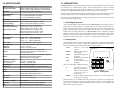
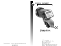
MONARCH INSTRUMENT
Instruction Manual
Phaser-Strobe
Portable Stroboscopes
Printed in the U.S.A. © Monarch Instrument 2002 all rights reserved
1071-4833-121
15 Columbia Drive
Amherst, NH 03031-2334 USA
Phone: (603) 883-3390
Fax: (603) 886-3300
E-mail: [email protected]
Website: www.monarchinstrument.com
Safeguards and Precautions
1.
Read and follow all instructions in this manual carefully, and retain
this manual for future reference.
2.
Do not use this instrument in any manner inconsistent with these
operating instructions or under any conditions that exceed the
environmental specifications stated.
3.
Use of this product may induce an epileptic seizure in persons prone
to this type of attack.
4.
Objects viewed with this product may appear to be stationary when
in fact they are moving at high speeds. Always keep a safe distance
from moving machinery and do no touch the target.
5.
There are lethal voltages present inside this product. Refer to the
section on Lamp Replacement before attempting to open this product.
6.
Do not allow liquids or metallic objects to enter the ventilation holes
on the stroboscope as this may cause permanent damage and void
the warranty.
7.
Do not allow cables extending from unit to come into contact with
rotating machinery, as serious damage to the equipment, or severe
personal injury or death may occur as a result.
8.
Do not direct strobe flash toward certain data collectors, as it may
temporarily interrupt data collector operation, and could result in loss
of stored data.
9.
This instrument may not be safe for use in certain hazardous
environments, and serious personal injury or death could occur as a
result of improper use. Please refer to your facility’s safety program
for proper precautions.
10.
This product contains sealed lead acid batteries which must be
disposed of in accordance with Federal, State, & Local Regulations.
Do not incinerate. Batteries should be shipped to a reclamation facility
for recovery of the metal and plastic components as the proper method
of waste management. Contact distributor for appropriate product
return procedures.
11.
This instrument is not user serviceable. For technical assistance,
contact the sales organization from which you purchased the product
or Monarch Instrument directly.
LIMITED WARRANTY
SELLER warrants hardware products to be free from any defect in materials or workmanship
for a period of one (1) year from date of shipment to BUYER. SELLER’s entire liability and
BUYER’s sole and exclusive remedy resulting from any defect in workmanship or material
in the hardware product covered by this limited warranty shall be limited to and fully
discharged by the SELLER’s option of replacement or repair of such item without charge.
The limited warranty provided in this clause is in lieu of all other warranties, expressed or
implied, arising by law or otherwise. ALL IMPLIED WARRANTIES OF MERCHANTABILITY
AND FITNESS FOR A PARTICULAR PURPOSE ARE EXCLUDED. This limited warranty
shall not be modified except by an arrangement signed by both parties specifically
referencing this clause.
SELLER warrants that any software supplied will operate in accordance with the
documentation or manual supplied therewith in all material respects when used in strict
compliance with such documentation or manual. Notwithstanding the foregoing, BUYER
acknowledges that, since software is complex and therefore may have defects, BUYER’s
sole and exclusive remedy for any such defects or breach of this warranty shall be to require
SELLER, within a reasonable period of time, to provide all reasonable programming services
to correct programming errors in the software. Except as provided above SELLER MAKES
AND BUYER RECEIVES FROM SELLER NO EXPRESS OR IMPLIED WARRANTIES OF
ANY KIND WITH RESPECT TO ALL OR ANY PORTION OF SOFTWARE AND BUYER
HEREBY AGREES AND ACKNOWLEDGES THAT IT ACCEPTS THE SOFTWARE IN ‘AS
IS’ CONDITION. SELLER HEREBY EXPRESSLY EXCLUDES ANY IMPLIED
WARRANTIES OF MERCHANTABILITY OR FITNESS FOR A PARTICULAR PURPOSE
WITH RESPECT TO THE SOFTWARE. BUYER agrees that any specific right or remedy
granted to BUYER hereunder with respect to any breach or default by SELLER shall be in
lieu of all other rights and remedies otherwise available to BUYER at law or in equity as the
result of such breach or default, regardless of whether based on contract, tort, strict liability,
or other theory of liability.
IN NO EVENT SHALL SELLER BE LIABLE FOR ANY SPECIAL, INDIRECT, INCIDENTAL,
CONSEQUENTIAL, OR PUNITIVE LOSSES OR DAMAGES (INCLUDING, BUT NOT
LIMITED TO, LOSSES OR DAMAGES FOR ANY LOST PROFITS OR LOST DATA) AS
THE RESULT OF ANY BREACH OR DEFAULT BY SELLER WITH RESPECT TO THE
HARDWARE OR SOFTWARE, EVEN IF SELLER HAS BEEN ADVISED OR MADE AWARE
OF THE POSSIBILITY OF ANY SUCH LOSSES OR DAMAGES AND REGARDLESS OF
WHETHER THE CLAIM IS BASED ON CONTRACT, TORT, STRICT LIABILITY, OR OTHER
THEORY OF LIABILITY.
This limited warranty does not extend or apply to consumables (including, but not limited to,
lamps and batteries, if applicable) or equipment, instruments or accessories which are
warranted separately by the original manufacturer of these items.
DECLARATION OF CONFORMITY
TABLE OF CONTENTS
1.0 INTRODUCTION ..................................................................... 1
As Manufacturer:
Monarch Instrument
1.1
Direct Digital Synthesis ...................................................................... 1
Division of Monarch International Inc.
15 Columbia Drive, Amherst NH 03031 USA
1.2
Display Panel ..................................................................................... 1
declares under Monarch’s sole responsibility that the product:
Name:
Models:
NovaStrobe - Stroboscope
PB Phaser-Strobe
2.1
Power ................................................................................................ 2
2.2
Input / Output Connections ............................................................... 2
3.0 OPERATION ........................................................................... 3
to which this declaration relates is in conformity with the following standards:
EMC:
2.0 PREPARATION FOR USE ...................................................... 2
EN50082-1:1997
EN50082-2:1995
EN55011:1991 Group 1 Class B
3.1
Using the Knob .................................................................................. 3
3.2
Internal Mode - Standard Strobe Operation ....................................... 4
3.3
External Mode - External Input Required ........................................... 4
3.4
External Delay Modes ........................................................................ 5
3.4.1 External Phase Delay .............................................................. 5
3.4.2 External Phase Delay - Auto Operation .................................... 5
3.4.3 External Time Delay ................................................................. 6
4.0 MEMORY ................................................................................ 6
and therefore conforms with the requirements of Council Directive
89/336/EEC relating to electromagnetic compatibility. Curtis-Straus
Laboratories performed the testing of this product. (Report No
980555-1)
4.1
Storing Settings ................................................................................. 6
4.2
Recalling Settings .............................................................................. 7
5.0 USING THE STROBOSCOPE TO MEASURE RPM .............. 7
6.0 LIMITATIONS OF REMOTE OPTICAL SENSORS (ROS-5P) 8
7.0 LAMP AND FUSE REPLACEMENT ....................................... 8
11th August 1998
Manufacturer (Amherst, NH)
Alan Woolfson, VP Engineering
(Authorized Signature)
7.1
Lamp Replacement ........................................................................... 8
7.2
Fuse Replacement ............................................................................ 9
8.0 BATTERY AND POWER SUPPLY SPECIFICS .................... 10
10.0 OPTIONS AND ACCESSORIES
8.1
Displaying Battery Charge Percentage ............................................ 10
C-4040
Set of mating 1/8 inch (3.5mm) male phone plugs for external input / output
8.2
Low Battery Indication ..................................................................... 10
CA-4044-6
8.3
Charging the Batteries ..................................................................... 10
6 foot (1.8M) input / output cable, 1/8 inch (3.5mm) male phone plug to male
BNC connector
CA-4045-6
8.4
External Power Supply/Charger ....................................................... 10
6 foot (1.8M) input / output cable, 1/8 inch (3.5mm) male phone plug to 1/8
inch (3.5mm) male phone plug for daisy chaining strobes together
8.5
Battery Disposal ............................................................................... 11
CC-7
Latching carrying case for Strobe with provision for accessories
PSC-3
AC Power Supply/Charger, 115 VAC - 50/60 Hz; Allows continuous operation
from AC mains or charges batteries
PSC-4
Same as above except 230 Vac - 50/60 Hz
R-5
Standard recharger, 115 Vac - 50/60 Hz (14 hour)
R-6
Same as above except 230 Vac - 50/60 Hz
L-1903
Digital Stroboscope replacement lamp
SPC-1
Splash proof Protective Cover for battery model Stroboscopes
ROS-5P
Remote Optical Sensor with 8 foot (2.5 m) cable for triggering strobe
T-5
Reflective tape. 5 foot (1.5 m) roll, 0.5 inch wide
MT-190P
Magnetic Sensor/Amplifier with 8 foot (2.5 m) cable for triggering strobe
IRS-5P
Infrared Sensor for use without reflective target at 0.5 inch (12 mm) gap with 8
foot (2.5 m) cable for triggering strobe
RLS-5P
Remote Laser Sensor with 8 foot (2.5 m) cable for triggering strobe
9.0 SPECIFICATIONS ................................................................ 12
10.0 OPTIONS AND ACCESSORIES .......................................... 13
13
9.0 SPECIFICATIONS
Adjustment Knob
all ranges and models
Rotory knob with 32 detents per rev. Any value can be
changed in decade steps (powers of 10) from 0.0001 per
detent to 10,000 per detent (depends on mode selected).
Time Base
Ultra stable Crystal Oscillator Controlled
INTERNAL MODE
Flash Range
30.0 - 32,500.0 FPM (Flashes per Minute)
0.5 - 541.67 FPS (Flashes per Second)
1.0 INTRODUCTION
The Phaser-Strobe is an extremely sophisticated instrument with many features never before available
in a stroboscope, yet remains simple to operate. Select only the features you need. Its internal
microprocessor with “Direct Digital Synthesis” enables precise settings and measurement which
are unique to the Phaser-Strobe, providing the widest flash range of any stroboscope.
The unit can store and recall three full, user programmed settings in non-volatile memory, as well as
last used settings so that the unit “remembers” all the settings when the power is turned off.
The Auto Step mode enables the user to view high speed moving parts in slow motion, with both the
rate and step size user programmable.
Update Rate
Instantaneous
Flash Rate Resolution and
Accuracy (setting)
100.00 to 2999.95 FPM (Flashes per Minute)
3000.0 to 32500.0 FPS (Flashes per second)
1.1 Direct Digital Synthesis
EXTERNAL MODE
Flash Range and Display
External flash rates to 0 are acceptable
0.0833 to 541.67 ±0.01% Accuracy - FPS
5.0000 to 9,999.9 ±0.01% Accuracy - FPM
10,000 to 32,500 ±0.01% Accuracy - FPM
33,000 to 200,000 ±0.01% Accuracy - FPM
550.00 to 3,333.3 ±0.01% Accuracy - FPS
“Direct Digital Synthesis” is the method by which the Phaser-Strobe’s internal microprocessor
generates all the signals required to set internal flash rates, time delays and phase shifts. In
analog stroboscopes, these values are adjusted using a single or multiple turn potentiometer
(knob), which generally lack sensitivity and tend to drift with time. It is very difficult to set
absolute values on analog stroboscopes. The Phaser-Strobe, however, synthesizes all signals
digitally, in small, very precise steps, all derived from a stable crystal oscillator. In the internal
flash mode, these steps are as small as 0.05 flashes per minute. Thus absolute values may be
dialed in very easily and accurately. See section 3.1 Using the Knob for more details.
Display only (no flash)
Update Rate
0.5 Seconds typical
D elay - Degrees *
(and display)
0 to 359 ± 0.1
100 to 3499.9 FPM
0 to 355 ± 0.1 3500 to 9999.9 FPM
0 to 350 ± 0.1 10000 to 32000 FPM
Delay - Time *
0 to 6500 milliseconds ± 0.0001 seconds
Auto Step Mode
-Step Size
-Step Rate
0.0 - 180° -see note
0.0001 to 6.5 seconds per step
Memory
Store three full settings in non-volatile memory.
Last settings before power down remembered and
restored on next power up.
Display
6-digit alphanumeric display shows information in English.
Battery charge and low battery indication.
Individual chevrons for mode display.
Light Power - Average
Instantaneous (per flash)
(auto change over)
10W
150 mJoule Low Flash Rate
50 mJoule High Flash Rate
Flash Duration
10 - 30 microseconds typical
Input Power
Internal Rechargable Batteries. External 7VDC 18W
Weight
2 1/2 lbs (1.2 kg) including batteries
Options
Line Powered Supply / Charger
Interface Cables, Remote Optical Sensor.
Output Pulse
500υsec 5VDC typical
Input Pulse
20υs min, TTL to 24VDC max
Sensor Power Supply
6VDC @ 50mA
Calibration
NIST traceable calibration certificate. (standard)
Note *
Minimum delay is 50υsec in all delay modes
12
1.2 Display Panel
The display panel consists of a backlit display with six alphanumeric digits that indicate modes,
flash rates, delays, etc. (see Figure 1). Below the six digits are five small chevrons (!) which
indicate the present mode of value displayed, and are described below:
AUTO
PHASE
TIME
FPS
FPM
Indicates Auto mode
is active
Indicates Phase Delay is
on the display
Indicates Time Delay is on
the display
Flashes Per Second (hertz)
is on the display
Flashes Per Minute is on
the display
Other icons in the display include the following:
!
----LO BAT
On Target Indicator Blinks at input frequency
Indicates input frequency
Figure 1 Display Panel
exceeds the limit of
the stroboscope
Flashes on display when the battery is getting low. It is on steady when the
strobe must be recharged.
Below the display are six membrane buttons that control the operation of the Stroboscope.
The operation of these buttons is explained within section 3.0 Operation. The red LEDs in the
top left corner of the DELAY and EXT buttons and the chevrons above AUTO, PHASE and
TIME indicate the operating mode.
1
2.0 PREPARATION FOR USE
The Strobe may be hand held or mounted on a tripod or other user supplied bracket using the ¼-20
UNC bushing at the base of the handle.
2.1 Power
The Phaser-Strobe has internal rechargeable batteries and may also be powered by an optional
external AC power supply. The unit should be charged before use (see section 8.3 Charging
the Batteries), or can be run continuously from the AC mains with the optional power supply
(PSC-3 or PSC-4, see section 8.4 External Power Supply/Charger). The Phaser-Strobe can
operate continuously in excess of 60 minutes at 6000 flashes per minute from fully charged
batteries. The strobe has a protection feature that prevents the strobe from operating if the
battery voltage is low. This condition is indicated by no flash and the display starts blinking
“LO BAT”. At this time the batteries must be recharged. The actual operating time of the
stroboscope depends on the flash rate and duty cycle of operation. Slower flash rates increase
the operating time.
2.2 Input / Output Connections
The Phaser-Strobe has input and output jacks on the left side of the
! !
stroboscope (see Figure 2). These can be used for external triggering
! "
Out In
or synchronization (daisy chaining two or more strobes). These jacks
accept 1/8" (3.5mm) phone plugs (input – stereo, output – mono).
Figure 2 Input/
The jacks’ outer connection (barrel) is common and the inner or center
Output Jacks
connection is the signal (see Figure 3). The input jack also has a
middle connection which provides power to an input sensor. The
input and output are TTL compatible. Refer to section 10.0 Options and Accessories for
interface cables.
To power the strobe with the external power supply/charger (PSC-3 or PSC-4):
1. Plug the power supply/charger cable into the recharger socket (located below the
display panel behind the handle).
2. Plug the power supply/charger into an AC mains wall outlet.
3. Move the switch on the power supply/charger to “RUN”.
The stroboscope may operate in the “CHARGE” setting, but will in fact be drawing power
from its internal batteries. An LED (light emitting diode) on the front of the power supply
indicates the unit is on.
NOTE: If the batteries are depleted, they will need to be charged for about 10 minutes before
trying to run the strobe from the power supply/charger.
WARNING: Do not leave the power supply/charger plugged into the PhaserStrobe if there is no AC applied to the power supply/charger.
8.5 Battery Disposal
Prior to disposing of the Phaser-Strobe, the user must remove the sealed lead acid batteries.
To do this, remove the lens, reflector and lamp as detailed in the Lamp Replacement section.
This will expose 4 screws that must be removed so the reflector housing can be dismantled.
There are four additional screws in the case half opposite the input and output jacks that must
be removed. The case halves can now be separated, exposing the batteries. Remove the
cables from the batteries and place tape over the battery terminals to prevent them from shorting.
The batteries should be sent to a recycling center or returned to the factory. The rest of the
parts may now be disposed of.
The optional ROS-5P (Remote Optical Sensor), MT-190P (Magnetic), IRS-5P (Infrared), or
RLS-5P (Laser) sensors may also be used to trigger the unit.
NOTE: When using external sensors that are powered by the Phaser-Strobe, i.e. Remote
Optical Sensor (ROS-5P), the sensor must be plugged in before the stroboscope is
turned on, or the remote sensor may not be powered up.
Common
The input jack (" pointing
Signal Input
(GND)
into socket) enables an
+6V Out to
+6V Out to
external signal to trigger
Sensor
Sensor
the strobe. In order to use
Common
the external signal you
Signal Input
(GND)
have to ensure that the
strobe is in the External
mode. Press the EXT
button until the red LED
in the top left of the EXT
Figure 3 Input Connector Connection Detail
button comes on. The
range for triggering is from dc to 542 flashes per second (32,500 flashes per minute). There is
typically a 5 µsec delay from trigger input to flash. The trigger source should provide a pulse
with a minimum duration of 1 µsec.
2
11
8.0 BATTERY AND POWER SUPPLY SPECIFICS
8.1 Displaying Battery Charge Percentage
To view the current battery charge percentage, press the DISPLAY button to cycle the display
between FPM, FPS, PHASE, TIME, and the battery charge percentage. The battery charge
percentage will display the current battery charge level from 0 to 100% for about 2 seconds
and then automatically return to FPM. PHASE and TIME are skipped when not in an External
Delay mode.
When the strobe is not flashing, the battery charge percentage represents the percentage of
usable charge left in the batteries. When the strobe is flashing, the percentage value will be
lower. The percentage value will generally decrease with increasing flash rates giving the user
an indication of how much quicker the batteries will be discharged at the current flash rate.
8.2 Low Battery Indication
When the batteries are low, the display blinks “LO BAT” every half second. The strobe may
still be used for a short time. When the battery charge is further depleted, the strobe will stop
flashing, display “LO BAT” and then completely shut off. When “LOW BAT” is displayed, the
unit needs to be recharged (section 8.3 Charging the Batteries) or powered by the power
supply/charger (section 8.4 External Power Supply/Charger).
3.0 OPERATION
To turn on the stroboscope, depress and hold the trigger. The trigger may be locked in position
using the side locking button. To lock the trigger on, hold the unit in the right hand, depress the
trigger as far as it will go, and then use your thumb to press the locking button. You can release the
trigger and the trigger will be held in place. To release the trigger lock, simply depress the trigger
and then release.
8.3 Charging the Batteries
When the strobe is powered up, it will operate in the last mode selected prior to turn off. The
Phaser-Strobe is shipped from the factory in the Internal mode.
The unit may be recharged at any time. You do not need to wait until the low battery condition
is indicated.
To display the software revision and then do a display test, press and hold the display button and
then depress the trigger to turn on the strobe.
CAUTION: Use of power supplies or rechargers other than the one supplied
(R-5, R-6, PSC-3 or PSC-4) may damage the stroboscope and void
the warranty.
There are four operating modes for the Phaser-Strobe. These are Internal, External, External
Phase Delay, and External Time Delay. All but the Internal mode require an external input signal.
To charge the battery with the standard recharger (R-5 or R-6):
1. Release the trigger so the strobe is off.
2. Plug the recharger cable into the recharger socket (located below the display panel
behind the handle).
3. Plug the recharger into an AC mains wall outlet.
The recharger will fast charge the batteries for up to 5 hours (typically 3½ - 4 hours). Once the
fast charge is completed, the recharger will trickle charge the batteries (as indicated by all the
chevrons on the display coming on).
To charge the battery with the external power supply/charger (PSC-3 or PSC-4):
1. Release the trigger so the strobe is off.
2. Plug the power supply/charger cable into the recharger socket (located below the
display panel behind the handle).
3. Plug the power supply/charger into an AC mains wall outlet.
4. Move the switch on the power supply/charger to “CHARGE”. Charging takes
approximately 16 hours.
WARNING: The unit may be left on to charge overnight, but the unit should not
be left on charge indefinitely (more than 36 hours) as this will
damage the lead acid batteries.
8.4 External Power Supply/Charger
The external power supply/charger (PSC-3 or PSC-4) can also be used to run the stroboscope
continuously from the AC mains.
10
With no external input, the
Common
Signal Input
output jack (! pointing away
(GND)
from socket) provides a TTL
Common
Signal Input
(GND)
compatible pulse from the
strobe’s internal oscillator. If
an external input is applied,
the output pulse mimics the
Figure 4 Output Connector Connection Detail
input pulse delayed by
whatever delay is active. This output pulse may be used to trigger a second stroboscope
synchronously to illuminate larger areas. Many strobes can be “daisy chained”. The output
jack of the strobe is connected to the input jack of the next strobe causing all the strobes to
flash together and be controlled by the first strobe in the chain.
In the Internal mode, the knob adjusts the flash rate from 30 to 32,500 Flashes Per Minute (FPM).
In the External mode, an external signal pulse is used to trigger the flash and the knob has no
effect. In the External Phase Delay mode, the flash is triggered 1 to 359 degrees after each
external signal pulse. The knob sets the amount of delay in degrees. In the External Time Delay
mode, the flash is triggered 0.0005 to 6.5 seconds after each external signal pulse. The knob sets
the amount of delay in seconds.
3.1 Using the Knob
Although the knob on the Phaser-Strobe has an analog style, it is actually a digital encoder
that is connected directly to the microprocessor. The knob has very definite steps or clicks (32
per revolution) allowing very definite adjustment, and it can be turned continuously. This is
equivalent to having a 550-turn potentiometer in an analog unit. Of course you are not expected
to turn the knob 550 times to get from the slowest flash rate to the fastest!
Each time the knob is turned, the blinking digit is either incremented (clockwise) or decremented
(counter-clockwise). There is an automatic roll over to the next digit on the 0 to 9 or 9 to 0
change. It is possible to adjust from the lowest to highest values using a single digit adjustment.
By selecting a different blinking digit, the user can select the step size to increment or decrement
the flash rate (time delay or phase delay) of 0.05, 0.1, 0.5, 1, 10, 100, 1000 and 10,000 per
‘click’. When adjusting the flash rate, choose an increment value that will quickly get you in
the range you want to be, and then select smaller increments to fine tune the value.
NOTE: There are maximum and minimum values in each mode beyond which you cannot
adjust. In the Internal Flash mode, the maximum flash rate is 32,500 FPM. If you
are adjusting the rate in 1000 increments and you reach a value which on the next
3
increment would exceed the maximum, eg 32,000 to 33,000, the display will not
increment. Select a lower digit to increment.
There are two ways/modes to select a new blinking digit:
Knob 1 mode:
Push and hold in the knob and turn to select a new digit. The next digit to blink is
dependent upon the direction of the knob rotation.
Knob 2 mode (factory default):
Push and release the knob without turning it. The next digit to the right will be the blinking
digit. If the right most digit is blinking when the knob is pressed, the blinking digit will
wrap around to the left most digit. If the knob is turned when the knob is pressed in, the
existing blinking digit will be incremented or decremented and a new blinking digit will not
be selected.
2.
any more than is necessary to free the lens. The reflector is held in place by the front lens
and will come loose, but is not necessary to remove the reflector.
Hold the lamp with a cloth between your forefinger and thumb and rock it back and forth
gently while pulling out. Do not attempt to rotate the lamp. The lamp is socketed and
will come out easily when pulled.
WARNING: Do NOT touch the new lamp with bare fingers.
3.
The lamps are polarized and must be put into the socket matching polarity. Using a lint
free cloth, match up the red dot on the plug with the red dot on the socket and
gently rock the lamp back and forth while pushing it into place (see Figure 6). Make sure
the lamp is in straight and centered in the reflector hole.
CAUTION: Do NOT allow the reflector to contact the lamp.
To change between Knob 1 and Knob 2 modes, press and hold the DISPLAY and x2 buttons
together. The display will show Knob 1 or Knob 2 to indicate the new knob mode.
Red Dots
3.2 Internal Mode - Standard Strobe Operation
In the Internal mode the stroboscope generates it’s own signals and functions like a
regular stroboscope.
To put the strobe in Internal mode:
1. Press the AUTO button until the AUTO chevron in the display is off.
2. Press the EXT button until the LED in the top left of the EXT button is off.
In the Internal mode the flash rate can be adjusted using the black knob on the left of the unit
(see section 3.1 Using the Knob). The current flash rate is shown on the display.
The flash rate can be doubled or halved instantly by pressing the x2 or ÷2 buttons respectively
up to the maximum or minimum allowed.
Notches
The flash rate can be displayed (and adjusted) in Flashes per Minute or Flashes per Second
(FPM or FPS). Press the DISPLAY button to cycle between FPM, FPS, and a display of the
battery charge percentage that will automatically return to FPM after about 2 seconds. The
chevrons on the display indicate which measurement is currently displayed. The unit
automatically computes between FPM and FPMS so you can set the rate in FPM and then
view it in FPS by pressing the DISPLAY button.
Since you can only delay in the External mode, pressing the DELAY button while in the
Internal mode will cause the error message “EXT ->” to be displayed.
3.3 External Mode - External Input Required
In the External mode there are no adjustments the user can make. The flash rate is a function
of the input signal. This mode is used to synchronize the flash to an external event (from an
optical sensor, for example) to stop or freeze motion. The flash will be triggered on the falling
edge of the external input pulse.
To put the strobe in External mode:
1. Press the AUTO button until the AUTO chevron in the display is off.
2. Press the DELAY button until the LED in the top left of the DELAY button is off.
3. Press the EXT button until the LED in the top left of the EXT button is on.
Figure 6 Lamp Replacement
4.
Reinstall the reflector and then position the front lens in place matching up the notches on
the lens with the two small tabs on the housing to prevent lens rotation (see Figure 6).
Push the tabs on the front rim outward and press the lens into place.
7.2 Fuse Replacement
There is a 5 x 20 mm fuse inside the unit which may be accessed by removing the lens and
reflector (refer to section 7.1 Lamp Replacement). Under normal operating conditions, the
fuse should never blow. Examples of abnormal operating conditions would be foreign materials
entering the strobe, such as water, ink, etc. If the fuse needs to be replaced, replace only with
a fuse of the same type and value: Slow Blow - 3.15A fuse (part# 1062-3004-001).
As in the Internal mode, the actual flash rate can be displayed in Flashes per Minute or Flashes
per Second (FPM or FPS). Press the DISPLAY button to cycle between FPM, FPS, and a
display of the battery charge percentage that will automatically return to FPM after about 2
seconds. The chevrons on the display indicate which measurement is currently displayed.
4
9
For a two-point calculation the actual speed is given by:
RPM = AB/(A-B)
Pressing the DELAY button will put the unit into one of the two External Delay modes as
explained in the next section.
RPM = 2XY(X+Y)/(X-Y)2 where
X = (A-B) and
Y = (B-C)
3.4 External Delay Modes – External Input Required
For a three-point calculation:
If a Remote Optical Sensor or Magnetic Sensor is used to sense one pulse per revolution (External
mode), the readout will display directly in RPM (FPM) without any adjustment required.
In instances when you can shut down the device and install a piece of reflective tape, then an optical
tachometer is easier to use for RPM measurement. Stroboscopes should only be used when you
can’t shut down the device. The human eye is not easily tricked into seeing a stopped image by
a stroboscope when the flash rate is slower than 300 FPM. Therefore, stroboscopes should not be
used below 300 FPM for inspection or to measure RPM.
6.0 LIMITATIONS OF REMOTE OPTICAL SENSORS (ROS-5P)
Remote Optical Sensors (ROS-5P) have a limitation when used with the Phaser-Strobe because
they sense not only the reflective marker but the strobe flash as well. If the ROS is positioned near
the strobe, the light from the strobe may cause the ROS to trigger the stroboscope at the wrong time,
especially when using a delayed flash mode. The Phaser-Strobe has an “Input Blanking” feature
to allow it to ignore this false trigger.
Even with the Input Blanking, large delays cannot be obtained using an ROS if the strobe’s flash is
triggering the ROS. The duration of the ROS pulse in response to the strobe’s flash is about 0.5
milliseconds to 1.1 milliseconds depending on the flash rate. This limits the largest delay possible
because the flash swamps the signal from the ROS, and consequently it will not provide the pulse
from the reflective marker. If large delays are desired, reposition the ROS so it is away from the
strobe’s flash or use a magnetic sensor.
The Input Blanking feature itself limits the maximum delay, which is detrimental to non-optical
sensors. It is possible to disable (or enable) the blanking in the Phaser-Strobe.
To toggle the Input Blanking on or off, press and hold the x2 button and then press the ÷2 button.
The display will show “BLANK” when Input Blanking is on and “NO BLK” when it is off.
7.0 LAMP AND FUSE REPLACEMENT
7.1 Lamp Replacement
WARNING: Before attempting to remove the lamp, make sure the stroboscope
is turned off and any mains cord is removed from the AC outlet.
Allow the lamp to cool waiting at least 1 minute.
The stroboscope is designed to discharge the internal high voltages within 30 seconds. However,
caution should be exercised when replacing the lamp.
The lamp can be replaced by using just a pocket screwdriver. It is not necessary to remove
any screws to replace the lamp. A new spare lamp is supplied with each new PhaserStrobe Kit.
To change the lamp:
1. Push apart the two tabs on the side of the reflector housing and remove the front lens
using a small screwdriver to help pry one tab and lift the lens. Take care not to pry the tab
8
Pressing the x2 or ÷2 buttons has no effect on operation.
There are two External Delay modes: Phase Delay and Time Delay. In order to activate
these modes, the strobe must be in the External mode as indicated in the previous section.
To put the strobe in the Phase Delay mode or Time Delay mode:
1. Make sure the strobe is in External mode (see previous section).
2. Press the DELAY button. The display will show PHASE – TIME – OFF sequentially
as the DELAY button is pressed. When the display shows PHASE the strobe is in
the Phase Delay mode. When the display shows TIME the strobe is in the Time
Delay mode. When the display shows OFF the unit is in the External mode as
described in section 3.3. The LED in the top left of the DELAY button will be on
when the strobe is in the Phase Delay mode or Time Delay mode.
The display is extremely versatile in the External Delay modes. The flash rate can be displayed
in FPM or FPS, the Phase delay in degrees or the equivalent Time delay in seconds. The
internal microprocessor automatically computes between Phase delay and Time delay. Press
the DISPLAY button to cycle the display between FPM, FPS, PHASE, TIME, and a display of
the battery charge percentage that will automatically return to FPM after about 2 seconds. The
chevron below the display indicates which measurement is currently being displayed.
3.4.1 External Phase Delay Mode
In the External Phase Delay mode the user can delay the flash from 1 to 359 degrees
after a trigger from the external input. This enables the user to vary the stopped motion
image at any position (angle) without having to move the trigger source.
The user can vary the phase delay in increments as small as 0.1° using the black knob on
the left of the strobe. Changing the Phase is done in the same manner as changing the
flash rate (refer to section 3.1 Using the Knob.) There are some limitations to the Phase
delay at higher flash rates (refer to section 9.0 Specifications).
The Phase delay can be doubled or halved instantly by pressing the x2 or ÷2 buttons
respectively up to the maximum or minimum allowed.
3.4.2 External Phase Delay Mode – Auto Operation
There is a special mode of operation in the External Phase Delay mode called the Auto
mode. In this special mode, the user can set a phase step and a rate of increment and
have the Stroboscope automatically increase the phase delay at the set rate. This has the
effect of causing the object being viewed to appear to rotate in steps, giving a slow motion
effect to something that is rotating extremely fast. This effect is unique to the PhaserStrobe and opens new possibilities in the inspection and maintenance fields.
The External Phase Delay Auto mode is used to automatically change phase delay in
steps periodically to give a slow motion effect. A value stored in step determines the step
size in degrees. A value stored in rate determines the length of time between steps. Once
these values have been set, use the ON button to turn on the stepping. Using a small phase
step (<1 degree) and a small step rate (about 0.0100 seconds), a good slow motion effect
can be achieved.
To put the strobe in the External Phase Delay Auto mode:
1. Put the strobe in the External Phase Delay mode as explained in section 3.4.
5
2.
Press the MEMORY/AUTO button until “AUTO” is displayed. (When in the
Auto mode, the ‘AUTO’ chevron is displayed.)
When the “AUTO” chevron displayed, the secondary (white) button functions are active.
These are STEP, RATE, ON, and OFF.
To adjust the step size, press the STEP button. The display will show “STEP” for a
second and then show the current step size in degrees (phase delay). The blinking digit is
the one affected by turning the knob. Adjust the step size using the knob in the same
manner you would adjust the flash rate (see section 3.1 Using the Knob).
To adjust the rate in seconds, press the RATE button. The display will show “RATE” for
a second and then show the current update rate in seconds. The blinking digit is the one
affected by turning the knob. Adjust the step size using the knob in the same manner you
would adjust the flash rate (see section 3.1 Using the Knob).
To begin the Auto Phase Delay, press the ON (DELAY) button.
To stop or freeze the motion at any time, press the OFF (EXT) button.
The MEMORY/AUTO button enables you to exit the Auto mode, store the current
settings or recall previously stored settings (see section 4.0 Memory).
3.4.3 External Time Delay Mode
In the External Time Delay mode the user can delay the flash from 0.0005 to 6.5 seconds
after a trigger from the external input. This enables the user to vary the stopped motion
image at any point in the cycle without having to move the trigger source.
The user can vary the time delay in increments as small as 0.0001 seconds (0.1 milliseconds)
using the black knob on the left of the strobe. Changing the delay time is done in the same
manner as changing the flash rate (see section 3.1 Using the Knob).
The Time delay can be doubled or halved instantly by pressing the x2 or ÷2 buttons
respectively up to the maximum or minimum allowed.
4.0 MEMORY - STORING AND RECALLING
The Phaser-Strobe can to store and recall up to three complete settings. This is exclusive of a
fourth setting that is stored each time the stroboscope is powered down, and automatically restored
each time it is powered up. Settings can be stored for comparative purposes or for special testing
purposes. Storing and recalling can be done in any of the four modes described in section
3.0 Operation.
4.2 Recalling Settings
To recall previously stored settings:
1. Repeatedly press the MEMORY/AUTO button until the display shows “RECALL”.
The unit is now ready to recall the settings from one of the three memory locations.
2. The numbers 1, 2 and 3 in the top right corner of the DISPLAY, DELAY and EXT
buttons respectively refer to the memory locations available. Press either the 1, 2 or
3 button to recall and restore the previously stored settings.
NOTE: When recalling previously stored settings, the Stroboscope may be put into a different
mode that requires external inputs. Look at the EXT and DELAY button LEDs and
the AUTO chevron on the display to determine which mode the strobe is in. The
strobe can be put back in the Internal mode at any time by pressing the EXT button
and the LED in the top left of the EXT button will go out.
5.0 USING THE STROBOSCOPE TO MEASURE RPM
The primary use for a stroboscope is to stop motion for diagnostic inspection purposes. However,
the stroboscope can also be used to measure speed. In order to do this several factors need to be
considered. First, the object being measured should be visible for all 360° of rotation (e.g. the end
of a shaft). Second, the object should have some unique part on it, like a bolt, keyway or imperfection
to use as a reference point. If the object being viewed is perfectly symmetrical, then the user needs
to mark the object with a piece of tape or paint in a single location to be used as a reference point.
If the rotational speed is within the range of the stroboscope, start at the highest flash rate and adjust
the flash rate down. At some point you will stop the motion with only a single image of the object in
view. At a flash rate twice the actual speed of the image you will see two images. As you approach
the correct speed you may see three, four or more images at harmonics of the actual speed. The
first single image you see is the true speed. To confirm the true speed, note the reading and adjust
the stroboscope to exactly half this reading, or just press the ÷2 button. You should again see a
single image (which may be phase shifted with respect to the first image seen).
For example, when viewing a shaft with a single key way you will see one stationary image of the
key way at the actual speed and at 1/2, 1/4, etc, of the actual speed. You will see 2 images of the
key way at 2 times the actual speed, 3 key ways at 3 times, etc. The FPM equals the shaft’s
Revolutions Per Minute (RPM) at the highest flash rate that gives only one stationary image
of the keyway.
4.1 Storing Settings
To store settings:
1. Repeatedly press the MEMORY/AUTO button until the display shows “STORE”.
The unit is now ready to store the settings in one of the three memory locations.
2. The numbers 1, 2 and 3 in the top right corner of the DISPLAY, DELAY and EXT
buttons respectively refer to the memory locations available. Press the 1, 2 or 3
button to save the setup for later recall.
Saved settings can be recalled at any time, even if the unit is powered down and left for years.
6
Stopped Image 1/4 times 1/2 times
Flash Rate (FPM)
875
1750
1 time
3500
2 times
7000
3 times
10500
4 times
14000
Figure 5 Object Rotating at 3500 RPM
If the rotational speed is outside the full-scale range of the stroboscope, it can be measured using the
method of harmonics and multi-point calculation. Start at the highest flash rate and adjust the flash
rate down. Be aware that you will encounter multiple images. Note the flash rate of the first single
image you encounter, and call this speed “A”. Continue decreasing the flash rate until you encounter
a second single image, and call this speed “B”. Continue decreasing the speed until you reach a
third single image, and call this speed “C”.
7