1
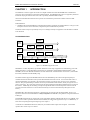
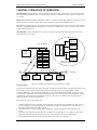
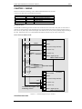
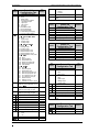
2408f & 2404f PROFIBUS Communications Handbook
Contents
CONTROLLER MODELS 2408f and 2404f
PROFIBUS-DP COMMUNICATIONS HANDBOOK
Contents
Page
Chapter 1
INTRODUCTION
Chapter 2
PRINCIPLES OF OPERATION
……………………………………………………..……………
Chapter 3
WIRING
2-1
………........……………………….………….………………
3-1
Cable Specifications
Chapter 4
3-2
CONTROLLER SET UP & NETWORK CONFIGURATION
..........................
Floating Point Data Formats
4-1
4-2
Diagnostic Information
Chapter 5
1-1
………………………..……..…...................…
4-3
THE WINDOWS CONFIGURATOR
……...........………………………………
Installing GSD Files
5-1
5-1
Chapter 6
TROUBLESHOOTING
Chapter 7
DEMAND DATA
Chapter 8
TAG ADDRESSES
…...………………………………………………..........
6-1
.........................................................................................
7-1
......................................................................................
8-1
Appendix A
GLOSSARY OF TERMS
Appendix B
EUROTHERM OFFICE ADDRESSES
……………………….……………………………..….
…………………………………………..
A-1
B-1
“This product is covered by one or more of the following US Patents:
5,484,206; Additional patents pending.
PDSIO and INSTANT ACCURACY are trademarks of Eurotherm.”
HA026290
Issue 1 January, 98.
Applies to 2408 f and 2404f Controllers software versions 3.22
i
2408f & 2404f PROFIBUS Communications Handbook
CHAPTER 1
Introduction
INTRODUCTION
This handbook is written for people who need to use a digital communications link and PROFIBUS-DP communication
protocols to supervise Eurotherm Controls Series 2000 instruments. The PROFIBUS-DP protocol is supported by Eurotherm
instruments carrying the suffix f in their order codes. Specifically 2408f and 2404f controllers.
It has been assumed that the reader has some experience of communication protocols and is familiar with Series 2000
instruments.
Related handbook:
• Installation and Operation Handbook for 2408 and 2404 Controller, Eurotherm part number HA025132. This gives a full
description of how to use the instruments, configuration options and definition of parameters.
Eurotherm Controls accepts no responsibility for any loss or damage caused by mis-application of the information contained
in this document.
THE PROFIBUS FAMILY
Area
Computer
Factory
Level
MMS, TCP/IP Backbone
CNC
Cell
Level
PC/VME
Host
PROFIBUS-FMS
PLC
PC
Field
Level
DCS
PROFIBUS-DP
Motor
Drives
I/O
Temp
Controller
PROFIBUS-PA
Field
Device
Transmitter
Field
Device
Figure 1-1: PROFIBUS Application Areas
PROFIBUS is a vendor independent, open fieldbus standard for a wide range of applications in manufacturing, process and
building automation. Vendor independence and openness are guaranteed by the PROFIBUS standard EN50170. With
PROFIBUS, devices from different manufacturers can inter-communicate. Suitable interfaces exist for PLCs, which include
the Siemens, Mitsubishi and Allen Bradley range.
The 2400f controllers support the PROFIBUS-DP variant of the PROFIBUS protocol which is designed especially for
communication between automatic control systems and distributed I/O at the device level. It is most often used to allow a
central Programmable Logic Controller or PC based control system to use external ‘slave’ devices for I/O or specialised
functions. The principal advantage is that these devices may be distributed around a machine, thereby saving on the cost of
point to point wiring. The ‘open’ nature of the network also permits equipment from different manufacturers to be mixed on
the same bus. Additionally, the off-loading of complex and specialised tasks such as PID temperature control lessens the
processing load on the central PLC so that its other functions may be carried out more efficiently and require less CPU
memory.
PROFIBUS-DP is described in DIN 19245 Part 3, and forms part of EN 50170 with P-Net and WorldFIP. However it is
important to note that P-Net and WorldFIP are wholly incompatible with PROFIBUS, using different wiring and transmission
technologies.
The PROFIBUS-DP network uses a high speed version of the RS485 standard, permitting baud rates of up to 12Mbaud. Note
however, that in order to guarantee electrical isolation standards, the 2400f Series supports rates of up to 1.5 MBaud only. A
table of network speed against segment length is given in Chapter 3.
A maximum of 32 PROFIBUS-DP stations (nodes) may be contained within a single network segment. Use of RS485
repeaters allows a total of up to 127 stations.
2408f and 2404f PROFIBUS Communications Handbook
1-1
Introduction
2408f & 2404f PROFIBUS Communications Handbook
PROFIBUS-DP is a multimaster, master-slave, token passing network. More detailed information, including a detailed guide
to products available, may be obtained from the various world wide PROFIBUS user organisations. You will find contact
information in trade magazines or by reference to http://www.profibus.com on the World Wide Web.
PROFIBUS is available in two other types, aimed at different application areas, as follows:
PROFIBUS-PA is designed especially for process automation. It permits sensors and actuators to be connected on one
common bus line even in intrinsically safe areas. PROFIBUS PA permits data communication and power over the bus, using
intrinsically safe, 2-wire technology according to the international standard IEC 1158-2, but may also be used on the standard
RS485 cabling for non-intrinsically safe applications.
PROFIBUS-FMS is the general purpose solution for communication tasks at the cell level.
2400f series controllers may be used on ‘combi’ networks which combine DP and FMS, but may only be used for PA when
the intrinsically safe physical medium is not used.
1-2
2408f and 2404f PROFIBUS Communications Handbook
2408f & 2404f PROFIBUS Communications Handbook
Principles of Operation
CHAPTER 2 PRINCIPLES OF OPERATION
PROFIBUS-DP distinguishes between master devices and slave devices. It allows slave devices to be connected on a single
bus thus eliminating considerable plant wiring typical with conventional communications systems. Figure 2-1 compares the
two systems.
Master devices determine the data communication on the bus. A master can send messages without an external request when
it holds the bus access rights (the token). Masters are also called active stations in the PROFIBUS protocol.
Slave devices are peripheral devices. Typical slave devices include input/output devices, valves, motor drives and measuring
transmitters. The 2408f and 2404f series Temperature Controllers are intelligent slaves. This means they will only respond to
a master when requested to do so.
PROFIBUS-DP is based around the idea of a ‘cyclical scan’ of devices on the network, during which ‘input’ and ‘output’
data for each device is exchanged.
Physical
Actuator 1
PLC I/O Mapping
I/O
PLC
Input
Output
Ladder
Program
Modules
Physical
Actuator 2
Physical
Actuator 3
Physical
Actuator 4
Figure 2-1a: Plant wiring
conventional comms. systems
I/O scanning
Physical I/O
Input
Input
Output
Output
Slave 1
Slave 2
Slave 3
Slave 4
Figure 2-1: PROFIBUS compared with conventional comms. systems.
I/O Data Exchange
The process of reading the inputs and writing to the outputs is known as an I/O data exchange. Typically, the parameters from
each slave device will be mapped to an area of PLC input and output registers, or a single function block, so that the
controlling ladder logic or program interfaces with the device as if it were an internally fitted module. It is NOT necessary,
therefore, for the programmer to know anything about the physical network. The process of network configuration is usually
performed using a PC based program which allows the devices on the network to be defined and device parameters to be
mapped into the PLC registers or function blocks.
The cyclical scan occurs in the following order:
1. Values from each slave device, ‘Input Data’, are first scanned over the network into a pre-defined set of input registers in
the master controller. Such values might be a set of digital input readings for a digital input unit, or the measured
temperature and alarm status from a PID controller.
2. The master then runs its control program, (such as a ladder logic program) using the input data read from the slave
devices.
3. The master writes output values (output data) into a pre-defined set of output registers. For example, one of the digital
inputs read in the input data might be used to select one of a set of setpoints to be sent to the PID controller.
4. These outputs are then written to each slave device, and the scan-process-write cycle repeats.
2408f and 2404f PROFIBUS Communications Handbook
2-1
Principles of Operation
2408f & 2404f PROFIBUS Communications Handbook
Typically no more than 32 bytes of input data and 32 bytes of output data are exchanged for each device during the data
exchange. Some PLC masters allow no more than this, although the PROFIBUS-DP standard provides the possibility of
transferring 236 bytes in each direction. The input and output data lengths for a given device are variable and it is possible to
have devices with only input data, only output data, or both.
The input and output data mixture used by a given slave device is defined by what is known as a GSD file. See Chapter 5 for
more details. For simple devices such as digital or analogue I/O blocks, this is fixed. However, since more complex devices
often have a much wider choice of possible values to send, it is usually possible to edit the GSD file to change the mapping of
device parameters onto Profibus inputs or outputs. This is the case with most Eurotherm implementations, which also allow
access to parameter data not in the GSD Input/Output data file. This is called Demand Data and is described further in
Chapter 7.
The GSD file is imported into the PROFIBUS Master Network Configuration software before the network is created.
NB:
2-2
PROFIBUS Input Data = Values sent from a device to a master controller or PLC,
PROFIBUS Output Data = Values sent from a master controller or PLC to a device
2408 f and 2404f PROFIBUS Communications Handbook
2408f & 2404f PROFIBUS Communications Handbook
Wiring
CHAPTER 3 WIRING
RS485 is the transmission technology used in 2404f and 2408f PROFIBUS-DP controllers.
Connections are made to the rear terminal block as follows:
Controller Terminal
HB
HC
HD
HE
HF
Designation
Shield
VP
B/B
A/A
D Gnd
Function
RF Ground for cable shielding
5 Volts for termination network only
RXD/TXD positive
RXD/TXD negative
0 Volts for termination network only
Earthing the shield
The PROFIBUS standard suggests that both ends of the transmission line be connected to safety earth. If such a course is
followed, care must be taken to ensure that differences in local earth potential do not allow circulating currents to flow, as
these can not only induce large common mode signals in the data lines, but can also produce potentially dangerous heating in
the cable. Where doubt exists, it is recommended that the shield be earthed at only one section of the network.
Do not connect the shield to DGND.
A
B
SHIELD
Twisted
pair
A
Station 1
HA
Not connected
HB
Shield
HC
VP (+5Vdc Voltage Potential)
HD
B (Rx/Tx +ve)
HE
A (Rx/Tx -ve)
HF
DGND (Digital ground)
B
2408f or 2404f controller
Twisted
pair
Intermediate stations
A
Last Station
HA
Not connected
HB
Shield
HC
VP (+5Vdc Voltage Potential)
HD
B (Rx/Tx +ve)
HE
A (Rx/Tx -ve)
HF
DGND (Digital ground)
B
390Ω
220Ω
Last station only requires 390Ω
terminating resistors
2408f or 2404f controller
Figure 3-1: Connection Diagram for up to 32 Slaves.
CABLE SPECIFICATIONS
2408f and 2404f PROFIBUS Communications Handbook
3-1
2408f & 2404f PROFIBUS Communications Handbook
Wiring
Either of the two cable types detailed below can be used. Please note that the cable types A and B,
specified below, are NOT related to the wire numbers A and B in the above wiring diagram. Type A
is recommended as it allows higher speed and longer cable length.
Characteristic
Impedance:
Cable
capacitance:
Core diameter:
Cable type:
Resistance:
Shielding:
Type A cable
135 to 165Ω at a frequency of 3 to 20 MHz.
Type B cable
135 to 165Ω at a frequency of > 100 kHz
< 30 pF per Metre
typ. < 60 pF per Metre
max. 0.34 mm², corresponds to AWG 22
twisted pair cable. 1x2 or 2x2 or 1x4 lines
< 110 Ohm per km
Copper shielding braid or shielding braid and
shielding foil
max. 0.22 mm², corresponds to AWG 24
twisted pair cable. 1x2 or 2x2 or 1x4 lines
Copper shielding braid or shielding braid and
shielding foil
Belden B3079A meets cable A specifications, but there are other choices. For more information refer
to the ‘PROFIBUS Product Guide’ produced by the PROFIBUS User Group.
Maximum line length per segment
Baud rate (kbit/sec)
Type A cable
Type B cable
3-2
9.6
1200m
1200m
19.2
1200m
1200m
93.75
1200m
1200m
187.5
1000m
600m
500
400m
200m
1500
200m
-
2408f and 2404f PROFIBUS Communications Handbook
2408f & 2404f PROFIBUS Communications Handbook
Controller Set Up & Network Configuration
CHAPTER 4 CONTROLLER SET UP & NETWORK CONFIGURATION
PROFIBUS-DP communications is available in Eurotherm 2408f and 2404f controllers. Other 2000 series controllers
(i.e. controllers without the f suffix) cannot be converted to PROFIBUS-DP comms, since a different microprocessor
board is required.
Main Differences between 2400f Controllers and Other Series 2000 Instruments.
2400f
The 20 program variant is not available
EI Bisynch is not available. The Instrument Programming System software, IPSG, therefore, cannot be used for cloning or
configuration.
Module slot H can only be used for PROFIBUS-DP or Modbus communications.
A PROFIBUS-DP module fitted to 2400f may be configured to Modbus communications if required. A Modbus module
fitted to any other 2000 series instrument cannot be configured to PROFIBUS-DP.
A PDSIO master or slave module can only be fitted in module slot J.
PROFIBUS-DP may be used with either mains powered and 24V AC/DC controllers, and in all respects, other than those
described above, they are standard units and may be used in exactly the same way as other 2400 series controllers.
CONTROLLER NODE ADDRESS AND CONFIGURATION
Assigning a Node Address
Connect the controller to the PROFIBUS network as described in Chapter 3.
Every controller on the network must have its own unique address to distinguish it from any other.
D
D
From the HOME display,
press
,
)O6
From the Comms List
Press
Press
5
66
59.
Press
until you reach the , list
to display the node address.
or
to set the desired address. B
From the Address List
Press
to display the Comms Status
This is a read-only diagnostic display
5A
Ready to run
59.
Comms running
to return to the HOME display
Note: The baud rate is automatically selected by the master.
2408f and 2404f PROFIBUS Communications Handbook
4-1
2408f & 2408f PROFIBUS Communications Handbook
Controller Set Up & Network Configuration
TO CONFIGURE THE CONTROLLER COMMUNICATIONS PARAMETERS
Select Configuration Level
“HOME”
display
Press Page
button
repeatedly
until Access
List appears
D
D
If incorrect
password
entered
)O6
1st press
2 secs
/
/
0
If the password has
been set to ‘0’ access is
or
to enter password
permanently unlocked
(factory default = 1)
& the lower readout
always shows PASS
2nd press
Note: Selecting
or
will allow direct entry
to these levels at this
point
04 9))
!/6/
/.
or
to select
/.
O6
3rd press
/.
/.
or
to enter
password
(factory default = 2)
0
At this point the
controller is in
configuration level
4th press
N.6
N0
/.
/.
Repeated pressing of “Page” button selects
configuration list headings in a continuous
loop
Select Comms Configuration List #
#
/.
Press
O
,
This should be a read-only parameter displaying ,
Press
9.
05/
Press
Press
5
8))
4-2
to display: Identity of module
Press
to display: Function
or
to set 9. = 05/
D
This selects PROFIBUS-DP protocol
to display: Comms Resolution
or
to select
9)) = Full, or N.6 = Integer 9)) is the recommended setting
2408f and 2404f PROFIBUS Communications Handbook
2408f & 2404f PROFIBUS Communications Handbook
Controller Set Up & Network Configuration
NETWORK CONFIGURATION
Having wired and configured the controller, the master PLC or PC based supervisory package must be configured to set-up
the parameters that it will be able to read and write to. This is known as ‘network configuration’.
The network is configured by importing ‘GSD’ files into your Master PROFIBUS network configuration software: This
should be explained in your network configuration software documentation. ‘GSD’ is an acronym of a German phrase
meaning ‘Device Database’.
The GSD files supplied with your 2408f and 2404f controllers are created using a Windows-based configuration tool. This
software is also separately available under ordering code PROF-ENG.
Two standard GSD files, are supplied on the disc:
EURO2400.GSD - standard parameter mapping. This is the default file, which is pre-configured for commonly used
parameters, as shown in Table 4-1 below.
EURD2400.GSD - standard parameter mapping with ‘demand data’, which allows random read/write to any parameter
within the controller. This is configured with the same default parameters.
PROFIBUS Input Data
Process Variable
0;
Working Setpoint
<0
Output 1
0
Summary Output Status Word
PROFIBUS Output Data
Setpoint 1
0 Setpoint 2
0 Setpoint Select
)
Acknowledge all Alarms
Table 4-1: Default Parameters.
The Summary Output Status Word is shown in Table 4-2., see ‘PROFIBUS DIAGNOSTICS’
It is possible to edit the above files or create new files using the Windows configurator.
The Master network configuration software uses the GSD files to produce a further file which is downloaded into your master
PLC or PC supervisory package. Once the configuration file has been downloaded, you can set the network running. If all is
well, the ‘REM’ beacon on the controller will start to flash, indicating that the data exchange is proceeding. The 66
parameter in the + list will show 59.. Input data will then be transferred from the controller to the master, and output
data will be transferred from the master to the controller.
If all 2400f controllers are of the same type only one GSD file needs to be configured.
FLOATING POINT DATA FORMATS
Data is returned or sent in the form of a single 16 bit integer value (register). Since the controllers use and display floating
point values, these are translated into integers in one of two ways, selected in controller configuration.
Full Resolution: The value is returned as a ‘scaled integer’, such that 999.9 is returned or sent as 9999; 12.34 is encoded as
1234. The control program in the PROFIBUS master must convert the numbers into floating point values if required. This is
the recommended format and is the factory default.
Integer Resolution. The floating point value is returned as a rounded integer, with the fractional part discarded. For example
999.9 would be returned as 1000; 12.34 would be returned as 12. Similar rules apply to output operations, although note that
it is only possible to send integer values so that setpoint values such as 11.5 cannot be used and so either 11 or 12 would have
to be chosen instead.
2408f and 2404f PROFIBUS Communications Handbook
4-3
2408f & 2408f PROFIBUS Communications Handbook
Controller Set Up & Network Configuration
PROFIBUS DIAGNOSTICS
One of the features of PROFIBUS-DP is that high priority diagnostic information is provided for each slave. The 2400f
Series uses the ‘Ext_Diag_Data’ area of this message (bytes 7 and 8) to send a word containing 16 bits of information
pertaining to the process and alarm status of the controller: The documentation supplied with your master should provide
further details on how to access diagnostic information.
BIT
0
1
2
3
4
5
6
7
8
9
10
11
12
13
14
15
DESCRIPTION
Alarm 1 State ( 0 = Safe 1 = Alarm )
Alarm 2 State ( 0 = Safe 1 = Alarm )
Alarm 3 State ( 0 = Safe 1 = Alarm )
Alarm 4 State ( 0 = Safe 1 = Alarm )
Manual Mode ( 0 = Auto 1 = Manual )
Sensor Break ( 0 = Good PV 1 = Sensor Broken )
Loop Break ( 0 = Good closed loop 1 = Open Loop )
Heater Fail
( 0 = No Fault 1 = Load fault detected )
Tune Active ( 0 = Auto Tune disabled 1 = Auto Tune active)
Ramp/Program Complete ( 0 = Running/Reset 1 = Complete )
PV out of range ( 0 = PV within table range 1 = PV out of table range )
DC control module fault (0= Good. 1= BAD)
Programmer Segment Synchronise (0 = Waiting, 1 = Running)
Remote input sensor break (0 = Good, 1 = Bad)
IP1 Fault
Reserved
Table 4-2: Summary Output Status Word
A ‘new diagnostics’ event will occur whenever any of the monitored events changes state...
Diagnostics Example
The example below may be returned which gives a summary of the Output Status Word information shown in the table
above.
Byte 1
XX
Byte 2
XX
Byte 3
24
Byte 4
XX
Byte 5
XX
Byte 6
03
Byte 7
40
Byte 8
30
Byte 6 signifies 3 bytes of information are included
Bytes 7 & 8 are 4030Hex or 01 00 00 00 00 11 00 00 Binary
From table 4-1:
Bit 4 is set Meaning the controller is in Manual Mode
Bit 5 is set Meaning the controller is in Sensor Break
Bit 14 is set Meaning the controller is in IP1 Fault
Global Commands
This is a further PROFIBUS-DP feature, which is not supported by the 2400f series of temperature controllers.
4-4
2408f and 2404f PROFIBUS Communications Handbook
2408f & 2404f PROFIBUS Communications Handbook
The Windows Configurator
CHAPTER 5 THE WINDOWS CONFIGURATOR
The Windows Configurator creates a ‘GSD’ file which provides a simple way of mapping device parameters into the PLC or
supervisory package input/output registers. The GSD file is imported into a PROFIBUS Master which in turn produces a file
that is downloaded into the PLC or supervisory package. It works on the ‘drag and drop’ principle by clicking on parameters
within lists (which correspond to the parameter lists in the controller) and dragging the chosen parameter to input or output
windows.
INSTALLATION
The program will run on Windows 3.1, Windows 95 or Windows NT.
To install the program, place the Eurotherm PROFIBUS-DP Support Disc in your drive and run A:\SETUP.EXE from the
program manager or Windows explorer.
Follow the on-screen prompts to install the configurator. These prompts will ask for:
• User and Company name.
• Set up will install Profconf in the directory C:\europrof. To install to a different directory, click browse and select another
directory.
• Set up will add program icons to the program folder, but you may type a new folder name or select one from the existing
folders list.
• Set up will then launch the program
• The screen layout shown below is the default screen supplied on the EURO2400.GSD file
Figure 5-1: The Default Configurator Screen Layout.
Leave the mouse cursor over a portion of the screen to see a hint explaining how it works. Hints can be turned off via the
Help menu once you have learned how to operate the program.
Open a GSD file for modification or editing, or create a new file for the currently selected controller type, using the ‘file’
menu. Note, however, that only files for the Eurotherm products, which include 2400 f and T630, may be edited using this
program.
Selected input or output parameters may be printed using the ‘print’ command in the ‘file’ menu.
Standard Windows facilities for Save and Save As are provided, allowing GSD files to be written to disk.
The buttons on the task bar provide quick access to most of these functions.
The controller parameter set is represented by a box to the left of the screen. A set of tabs allows a group of parameters to be
displayed, corresponding to lists in the controller user interface. A separate list for 2400f series status words is also provided
for the controller type.
2408f and 2404f PROFIBUS Communications Handbook
5-1
2408f & 2404f PROFIBUS Communications Handbook
The Windows Configurator
To add a parameter to the PROFIBUS-DP Input Data, simply drag it from the Device Parameter list using the mouse, and drop
it into the Inputs list. Similarly, drop a parameter into the Outputs list to set PROFIBUS-DP Output Data. Alternatively,
double click on a parameter name to add it to the currently selected window - select the list by clicking on it - or use the arrow
button to the left of the input and output lists. You may change the order of the Input and Output List by dragging and
dropping between them. Parameters may be deleted or the list cleared using the buttons on the right hand side of the I/O lists,
or by pressing the right mouse button when the cursor is over a parameter name, whereupon a pop up menu will be displayed.
Select or remove support for ‘Demand Data’ (see Chapter 7) using the check box in the lower part of the screen. Add a short
description of the function of the GSD file in the lower window: this will usually be displayed by your network configuration
tool when selecting a device from the list.
Once the I/O data has been specified to your wishes, save the GSD file to disk: you may use any filename you wish. You may
then import it into your PROFIBUS-DP network configuration tool and use it in an application program. It is possible to save
several different GSD files for the same basic instrument, thereby setting up a library for different applications.
Example:
GSD file to allow gain scheduling using a PID settings stored in a PLC
Input Data
• Process Variable
Output Data:
• Proportional Band
• Integral Time
• Derivative Time
• Cutback High
• Cutback Low
In this application, the PLC monitors ‘Process Variable’ (actual temperature), and when it passes into a particular pre-set band,
sets the output data parameters from settings stored in the PLC.
Use the right mouse button when the cursor is over a parameter in the left hand window to determine its tag for demand data
operations.
A limit of 117 total input and output words, including the requirements for demand data, is imposed by the configurator.
When this limit is reached, it will no longer be possible to add parameters into either the input or output lists until other
parameters have been deleted. In any case it is advisable not to exceed 32 input and 32 output words in total, since some
masters are unable to deal with more.
To obtain a summary of the I/O memory map for the current GSD file, select ‘View I/O map’ from the file menu. This may be
pasted into the clipboard and placed into a document if required for project documentation. It may also be printed directly
from the File menu.
5-2
2408 f and 2404f PROFIBUS Communications Handbook
2408f & 2404f PROFIBUS Communications Handbook
Troubleshooting
CHAPTER 6 TROUBLESHOOTING
No Communications:
•
•
•
•
Check the wiring carefully, paying particular attention to the continuity of the A and B connections to the Master. Ensure
that the correct terminals have been wired to.
Access the # list in configuration level and check that the function (9.) is set to 05/ . If not, the controller is not
configured for PROFIBUS-DP.
Check Node Address (5) in the + list is correct for the network configuration in use.
Ensure that a PROFIBUS-DP Comms Module is installed in slot H of the 2404/8f. It can be identified by of the legend on
the plug-in module casing, and its distinctive shape:
EUROTHERM CONTROLS
SUB24/PB PROFIBUS
Iss No.
AH026222 U002
DATE
•
•
•
•
•
•
Ensure that the network is correctly configured and the configuration has been transmitted correctly to the PROFIBUS-DP
master.
Verify the GSD file in use is correct by loading it into the GSD File Configuration. This will check the format.
Verify that the maximum line length for the baud rate in use is not exceeded (see table above). Note that the 2404/8f is
restricted to use at a maximum rate of 1.5 Mbaud.
Ensure that the last device (not necessarily a 2404/8f) in the network segment is correctly terminated (see wiring diagram).
Ensure that no devices other than those at the end of a network segment have termination networks fitted.
If possible, replace suspect device with a duplicate and retest.
Intermittent Failure to Communicate.
Intermittent Flickering of Status From ‘5A’ to ‘59.’.
Diagnostic Status Changing but no Alarms Present in the Controller.
•
•
•
•
•
•
Verify wiring, paying particular attention to screening.
The I/O data length may be too long. Some PROFIBUS-DP Master implementations can accept no more than 32 input
and 32 output words per slave device. Verify by reference to documentation of the Master.
Verify that the maximum line length for the baud rate in use is not exceeded (see cable specifications). Note that the
2404/8f is restricted to use at a maximum rate of 1.5 Mbaud.
Ensure that the last device (not necessarily a 2404/8f) in the network segment is correctly terminated (see wiring diagram).
Ensure that no devices other than those at the end of a network segment have termination resistors fitted.
Verify operation with a duplicate device if possible.
Setpoint, Output Power, Auto/Manual etc ‘jammed’ to one setting and cannot be altered using controller
front panel.
•
•
•
•
PROFIBUS-DP writes all ‘output’ data continuously, so that if Output Power, Setpoint, or Auto/Manual status are
included in the output data, their settings, as stored in the master data registers, will override any setting entered using the
front panel of the controller. To avoid this, here are some suggestions for possible techniques.
Use ‘Demand Data’ to write parameter values only when changes are required
(Setpoints only) Use 0
as a ‘manual’ setpoint, selectable locally using a digital input or key switch, and 0 as a
‘PROFIBUS-DP remote’.
Note that when the network fails and the instrument goes off-line to PROFIBUS-DP, the front panel will regain full
control, so that the controller may be used as a local ‘island’ of control.
Data format or parameter data seems incorrect
• Verify that the data format is correctly configured (‘9))’, or ‘N.6’), from the # /. list in the controller.
Verify that the GSD file is correct for the given application by loading it into the GSD file configurator program.
2408f and 2404f PROFIBUS Communications Handbook
6-1
2408f & 2404f PROFIBUS Communications Handbook
Demand Data
CHAPTER 7 DEMAND DATA
The GSD file is used to define those parameters which need to be updated continuously. It is, therefore, a convenient way to
transfer input and output data between the controller and the master PLC or Supervisory Computer. It is, however, wasteful in
comms bandwidth if, for example:
1. It is used to read or write to occasionally accessed data, such as autotune or a three term value
2. Complex read/writes are performed which require a lot of data exchange, such as setting up and running a programmer.
For these parameters use the ‘Demand Data’ sub-protocol. This allows read/write access to any parameter within the
controller using, what are known as ‘Tags’ which identify the parameters. Each parameter has a unique 16 bit tag, a full list of
which is given in the next chapter.
When Demand Data is used, the first four (16 bit) registers of the PROFIBUS-DP Output data are reserved to encode a
‘request message’ using the protocol. The control program is responsible for writing values into the first four registers to
make requests. The instrument uses the first four registers of PROFIBUS-DP input data as a ‘response message’ to return
values and indicate success or failure of the operation that was requested.
It is enabled by the PROFIBUS-DP master setting the first byte of the module configuration data to 73 hex. This is done
automatically, when:
• Using the EURD2400.GSD GSD file.
• The check box (Use Demand Data) in the EURO2400.GSD configurator program is selected.
Demand Data is supported by standard software in many PLCs. It can be implemented easily as part of the PLC program.
2408f and 2404f PROFIBUS Communications Handbook
7-1
Demand Data
2408f & 2404f PROFIBUS Communications Handbook
Demand Data uses the first 8 bytes in both the request and response message of the cyclic Data Exchange.
DEMAND DATA STRUCTURE
Read Request (from PLC)
PLC Output Register
Output Data
Number
The first four registers are reserved for demand data.
The control program is responsible for writing values into
these first four registers to make requests.
1
Command Code and Parameter
Tag
2
Extended Parameter Tag
3
Reserved
4
Anything
The registers that follow are used for the fixed output
data defined by the GSD file
5
Value or State
6
Value or State
7
Value or State
etc.
Value or State
Write Request (from PLC)
PLC Output Register
Output Data
Number
The first four registers are reserved for demand data.
The control program is responsible for writing values into
these first four registers to make requests.
1
Command Code and Parameter
Tag
2
Extended Parameter Tag
3
Reserved
4
Value or State to be written
The registers that follow are used for the fixed output
data defined by the GSD file
5
Value or State
6
Value or State
7
Value or State
etc.
Value or State
7-2
Response to Read Request (from Controller)
PLC Input Register Number
Input Data
The first four registers are reserved for responses to
demand data.
1
Command Code and Parameter
Tag
2
Extended Parameter Tag
3
Reserved
4
Returned value
The registers that follow are used for the fixed input data
defined by the GSD file
5
Value or State
6
Value or State
7
Value or State
etc.
Value or State
Response to Write Request (from Controller)
PLC Output Register
Output Data
Number
The first four registers are reserved for responses to
demand data.
1
Command Code and Parameter
Tag
2
Extended Parameter Tag
3
Reserved
4
Write error code
The registers that follow are used for the fixed output
data defined by the GSD file
5
Value or State
6
Value or State
7
Value or State
etc.
Value or State
2408f & 2404f PROFIBUS Communications Handbook
2408f & 2404f PROFIBUS Communications Handbook
Demand Data
THE COMMAND CODE AND TAG ARE ENCODED INTO REGISTER 1 AS FOLLOWS:
Bits 15-12
Command Code
Bit 11
Reserved
Bit 10 - 0
Parameter Tag
Because only 11 bits are available for the Parameter Tag, the maximum tag allowable for standard demand data operations is
2048. The 2400f series controller allows tag values of up to 16383, therefore, extended tags have been provided using register
2. This is particularly important if ramp/dwell programs or configuration information is to be transferred over PROFIBUS-DP.
Fields in a request (output registers) should be set as follows:
NB: Eurotherm Extensions are printed in bold italic text
Command (Hex)
Request (Master to Slave)
Parameter Tag
0000
1000
2000
3000
4000
No Command
Read Request
Write Request
Extended Read Request
Extended Write Request
Tag to Read
Tag to Write
Must be Zero
Must be Zero
Extended
Parameter Tag
Tag to Read
Tag to Write
Value
Value to write
Value to Write
Valid responses to a given command are as follows:
Command
Field in request
(output register)
0000
1000
1000
2000
2000
3000
3000
4000
4000
Command
Field in response
(input register)
0000
1000
7000
1000
7000
1000
7000
1000
7000
Meaning
Returned Value
(input register 4)
Acknowledge No Command
Tag Read Successfully
Tag Read Not Successful
Tag Written Successfully
Tag Write Not Successful
Extended Tag Read Successfully
Extended Tag Read Not Successful
Extended Tag Written Successfully
Extended Tag Write Not Successful
Value Read
Error Code (see below)
Write Request
Value Read
Error Code (see below)
Error Code (see below)
The command field in the response message either
• Confirms that no operation has been requested
• Indicates that a Read or Write request has been completed successfully
• Indicates that a Read or Write has failed.
Error Codes in input register 4 are as follows.
Error Code
0
1
2
Meaning
Invalid Tag Number
Read Only Parameter
Value out of range
2408f and 2404f PROFIBUS Communications Handbook
7-3
2408f & 2404f PROFIBUS Communications Handbook
Demand Data
Worked example 1 - Starting an Autotune
An autotune is a good example of an operation that might be performed using the demand data sub-protocol, since it is a
relatively infrequent operation and it would be wasteful to dedicate PROFIBUS-DP I/O data to such a task.
Request 1: Clear any previous demand data requests. You should do this at the start of any sequence of operations using
demand data in order to ensure that the system is properly initialised.
PLC Output Register Number
1
2
3
4
Output Data
0
Anything
Anything
Anything
Comment
Response 1: Wait until the following response message is received in the input data:
PLC Input Register Number
1
2
3
4
Input Data
0
Anything
Anything
Anything
Comment
Request 2: Write 1 to Autotune enable. Note Tag address is 270 (decimal) see ‘TAG ADDRESSES’ Chapter 8
PLC Output Register Number
1
2
3
4
Output Data
8462
Anything
Anything
1
Comment
Write request 2000 (hex) (8192 dec) + tag address 270 (dec.) = 8462 (dec)
Write state 1 to enable Autotune see enumerators for each tag address in
Chapter 8
Response 2: Wait for one of the following responses to be received.
a. An error has occurred (Code 7)
PLC Input Register Number
1
2
3
4
Input Data
28942
Anything
Anything
1 or
2 or
3
Comment
Error 7000 (Hex) (28672 dec) + tag address (270 dec) = 28942
Invalid tag number
Read only parameter
Value out of range
b. No error
PLC Input Register Number
1
Input Data
4366
2
3
4
Anything
Anything
Anything
Comment
Successful write code 1000 (Hex) (4096dec) + tag address 270 (decimal)
= 4366
Request 3: If there was no error, poll Control Status Word (tag 76) until autotune complete.
PLC Output Register Number
1
Output Data
4172
2
3
4
Anything
Anything
Anything
Comment
Successful write code 1000 (Hex) (4096dec) + tag address 76 (decimal)
= 4172
To determine when Autotune is complete:
Look at the PROFIBUS-DP Input data until either bit 3 (Self Tune Fail) of the value field is set, or bit 12 (Autotune enabled)
is cleared. There is no need to set up more requests, since the value field will be automatically updated by the slave, but you
should not try to access other demand data until this operation has completed. Any value for register 1 other than 4172
signifies an error has occurred, in which case register 4 will contain an error code of 0 or 1 or 2.
PLC Input Register Number
1
3
4
7-4
Input Data
4172
Anything
Anything
XXXX
Comment
The value of the Control Status Word
2408f & 2404f PROFIBUS Communications Handbook
2408f & 2404f PROFIBUS Communications Handbook
Demand Data
Worked example 2 - Uploading Program Data
The 2400f series with PROFIBUS-DP may be configured with a ramp/dwell programmer option. It is often the case that
specific ramp dwell sequences need to be downloaded to an instrument. Because of the amount of data involved, it would be
impossible if only standard PROFIBUS-DP input and output frames were to be used. Use of the demand data protocol is the
only way the operation may be performed.
Note that if the programmer option is configured, the instrument defines two types of program data store. Program 0 holds a
copy of the currently running program (if any) which may be accessed or changed in ‘hold’ mode only. Programs 1, and 2, 3,
and 4 for a 4 programmer instrument, hold the actual program data and may be accessed at any time.
From the tag list, we find that the Program 1 has tags running from 8328 to 8463. This is above the maximum of 2047 for a
standard tag read, so we will need to use the Eurotherm extensions.
Note that a program download is essentially the inverse of this operation, using extended tag writes.
The sequence of operations to upload a ramp/dwell program is as follows:
Request 1: Clear any previous demand data requests. You should do this at the start of any sequence of operations using
demand data in order to ensure that the system is properly initialised.
PLC Output Register Number
1
2
3
4
Output Data
0
Anything
Anything
Anything
Comment
Response 1 Wait until the following response message is received in the input data:
PLC Input Register Number
1
2
3
4
Input Data
0
Anything
Anything
Anything
Comment
Request 2: Read from the first program address.
PLC Output Register Number
1
2
3
4
Output Data
12288
8328
Anything
Anything
Comment
Extended read tag 3000 (Hex)
Program 1 tag address,. see Chapter 8
Response 2: Wait for one of the following responses to be received.
a. An error has occurred
PLC Input Register Number
1
2
3
4
b.
Input Data
37000
Anything
Anything
0
1
2
Comment
Error 7000 (Hex) (28672 dec) + tag address 8328 (dec) = 37000
Invalid tag number
Read only parameter
Value out of range
No error.
PLC Input Register Number
1
2
3
4
Input Data
12288
8328
Anything
Anything
Comment
Extended read tag 3000 (Hex)
Program 1 tag address,. see Chapter 8
If there was no error, store the Program Value in the required memory location, increment register 2 in the request message,
and repeat until tag 8463 (end of program 1 segments) has been reached.
Tags
Parameter Tags may be obtained by reference to the following chapter. Note also that the GSD Configuration Program allows
the display of the tag for a given parameter, by clicking the right mouse button when pointing to the parameter.
2408f and 2404f PROFIBUS Communications Handbook
7-5
2408f & 2404f PROFIBUS Communications Handbook
Tag Addresses
CHAPTER 8 TAG ADDRESSES
Tag addresses are used to identify parameters in the controller and are identical to the Modbus addresses which are also listed
in the Series 2000 Communications Manual, Eurotherm Part No. HA 026230. Tag addresses are used with the demand data
protcol to set up input/output data in the PLC or supervisory PC.. They are repeated here in the order in which they appear in
the GSD file.
They can also be read from the Windows Configurator by pointing to the parameter and clicking the right mouse button.
Controller
Display
0
0
=D0
,B
B
B
,0
DO
8
9
10
11
Tag
Parameter Description
Address
Process Variable
Target setpoint
% Output power
For ON/OFF controllers the
following power levels must
be written:
Cool -100%
OFF
0%
Heat
100%
Working set point. Read only:
use Target set point or
currently selected set point (1
to 16) to change the value
Auto-man select
0: Auto
1: Manual
Pot Position
Valve Posn (computed by
VP algorithm)
VP Manual Output (alterable
in Man only)
Heater current (With PDSIO
mode 2)
Customer defined
identification number
Setpoint Span
Error (PV-SP)
Remote Input Value
1
2
3
5
273
317
53
12
13
14
15
BIT
Bit 0
Bit 1
Bit 2
Bit 3
Bit 4
Bit 5
Bit 6
Bit 7
60
80
629
552
39
26
Status Tab
Tag Address
Summary Output Status Word
75
BIT
0
1
2
3
4
5
6
7
Home Tab
DESCRIPTION
Alarm 1 State
( 0 = Safe 1 = Alarm )
Alarm 2 State
( 0 = Safe 1 = Alarm )
Alarm 3 State
( 0 = Safe 1 = Alarm )
Alarm 4 State
( 0 = Safe 1 = Alarm )
Manual Mode
( 0 = Auto 1 = Manual )
Sensor Break ( 0 = Good PV 1 = Sensor Broken )
Loop Break
( 0 = Good closed loop
1 = Open Loop )
Heater Fail
( 0 = No Fault
1 = Load fault detected )
Tune Active
( 0 = Auto Tune disabled
1 = Auto Tune active)
Ramp/Program Complete ( 0 = Running/Reset
1 = Complete )
PV out of range
( 0 = PV within table range
1 = PV out of table range )
DC control module fault (0= Good. 1= BAD)
2408f and 2404f PROFIBUS Communications Handbook
BIT
0
1
2
3
4
5
6
7
8
9
10
11
12
13
14
15
BIT
0
1
2
3
4
5
6
7
8
Programmer Segment Synchronise
(0 = Waiting,
1 = Running)
Remote input sensor break ( 0 = Good, 1 = Bad)
IP1 Fault
Reserved
Status Tab
Tag Address
Fast Status Byte
74
DESCRIPTION
( 0 = Safe 1 = Alarm )
( 0 = Safe 1 = Alarm )
( 0 = Safe 1 = Alarm )
( 0 = Safe 1 = Alarm )
( 0 = Auto 1 = Manual )
( 0 = Good PV 1 = Sensor Broken )
( 0 = Good closed loop 1 = Open
Alarm 1 State
Alarm 2 State
Alarm 3 State
Alarm 4 State
Manual Mode
Sensor Break
Loop Break
Loop )
Heater Fail ( 0 = No Fault 1 = Load fault
detected )
Control Status Word
76
DESCRIPTION
Control algorithm Freeze
PV input sensor broken
PV out of sensor range
Self Tune failed
PID servo signal
PID debump signal
Fault detected in closed loop behaviour (loop
break)
Freezes the integral accumulator
Indicates that a tune has completed successfully
Direct/reverse acting control
Algorithm Initialisation flag
PID demand has been limited.
Autotune enabled
Adaptive tune enabled
Automatic Droop compensation enabled
Manual / Auto mode switch
Instrument Status Word
77
DESCRIPTION
Config/Oper mode switch
Disables limit checking
SRL ramp running (Read Only)
Remote setpoint active
Alarm acknowledge switch.
Reserved
Reserved
Reserved
Reserved
8-1
2408f & 2404f PROFIBUS Communications Handbook
Tag Addresses
9
10
11
12
13
14
15
Reserved
Reserved
Reserved
Reserved
Reserved
Reserved
Reserved
Program Logic Status
14
15
BIT
0
1
2
3
4
5
6
7
8
9
10
11
12
13
14
15
DESCRIPTION
Program Output 1
( 0 = OFF 1 = ON )
Program Output 2
( 0 = OFF 1 = ON )
Program Output 3
( 0 = OFF 1 = ON )
Program Output 4
( 0 = OFF 1 = ON )
Program Output 5
( 0 = OFF 1 = ON )
Program Output 6
( 0 = OFF 1 = ON )
Program Output 7
( 0 = OFF 1 = ON )
Program Output 8
( 0 = OFF 1 = ON )
Reserved
Reserved
Reserved
Reserved
Reserved
Reserved
Reserved
Reserved
Digital Output Status Word
551
Parameter Description
162
BIT
0
1
2
3
4
5
6
7
8
9
10
11
12
13
14
15
DESCRIPTION
H Interface module telemetry (0 = Off, 1 = On)
J Interface module telemetry (0 = Off, 1 = On)
1A module telemetry
(0 = Off, 1 = On)
LB logic telemetry
(0 = Off, 1 = On)
LA logic telemetry
(0 = Off, 1 = On)
1B module telemetry
(0 = Off, 1 = On)
1C module telemetry
(0 = Off, 1 = On)
2A module telemetry
(0 = Off, 1 = On)
2B module telemetry
(0 = Off, 1 = On)
2C module telemetry
(0 = Off, 1 = On)
3A module telemetry
(0 = Off, 1 = On)
3B module telemetry
(0 = Off, 1 = On)
3C module telemetry
(0 = Off, 1 = On)
AA relay telemetry
(0 = Off, 1 = On)
Reserved
Reserved
Digital Input Status Word
87
BIT
0
1
2
3
4
5
6
7
8
9
10
11
12
13
DESCRIPTION
H Interface module
(0 = Off, 1 = On)
J Interface module
(0 = Off, 1 = On)
1A module
(0 = Off, 1 = On)
LB logic input
(0 = Off, 1 = On)
LA logic input
(0 = Off, 1 = On)
1B module telemetry
(0 = Off, 1 = On)
1C module
(0 = Off, 1 = On)
2A module
(0 = Off, 1 = On)
2B module
(0 = Off, 1 = On)
2C module
(0 = Off, 1 = On)
3A module
(0 = Off, 1 = On)
3B module
(0 = Off, 1 = On)
3C module
(0 = Off, 1 = On)
Reserved
8-2
Reserved
Reserved
SP Rate Limit Holdback Status
0: Inactive
1: Active
Pot Break
Freeze Control Flag
0: Controlling
1: Hold
SP Rate Limit Active Status
0: No setpoint rate limit
1: Setpoint rate limit active
Sensor Break Status Flag
0: Good
1: Sensor break
Power Failed flag
0: Good
1: Power fail detected
New Alarm Flag
Loop Break Status Flag
0: Good
1: Loop break
Integral Hold Status Flag
0: Good
1: Integral hold
SRL Complete Status
0: Setpoint rate limit incomplete
1: Setpoint rate limit complete
Remote Input Status Flag
0: Good
1: Fault
Sync Continue Flag
0: Continue
1: Awaiting synch
Tag
Address
41
350
257
275
258
259
260
263
264
277
280
281
2408f & 2404f PROFIBUS Communications Handbook
2408f & 2404f PROFIBUS Communications Handbook
Tag Addresses
Controller
Run Tab
Tag
Controller
Alarm Tab
Tag
Display
Parameter Description
Addres
s
Display
Parameter Description
Address
05"
66
00
@
!
6@0
!6
6!6
56
05!6
6
/96D
/96D
/96D
/96D
/96D
/96D
/96D
/96D
A.
!D
22
BBB
BBB
BBB
BBB
#@
#A
#@
#@
)6
Current program running
(active prog no.)
Program Status
1: Reset
2: Run
4: Hold
8: Holdback
16: Complete
Programmer setpoint
163
Program cycles remaining
59
Current segment number
Current segment type
0: End
1: Ramp (Rate)
2: Ramp (Time to target)
3: Dwell
4: Step
5: Call
Segment time remaining in secs
56
36
Segment time remaining in mins
63
Target setpoint (current
segment)
Ramp rate
160
161
Program time remaining
58
Fast run
0: No
1: Yes
Logic 1 output (current program)
0: Off (applies to all 8 logic
outputs)
1: On (applies to all 8 logic o/ps)
Logic 2 output (current
program)
Logic 3 output (current
program)
Logic 4 output (current
program)
Logic 5 output (current
program)
Logic 6 output (current
program)
Logic 7 output (current
program)
Logic 8 output (current
program)
Segment synchronisation
0: No
1: Yes
Flash active segment in lower
display
Advance Segment Flag
57
5
464
5D6
23
29
465
O!
Alarm 1setpoint value
13
Alarm 2setpoint value
14
Alarm 3setpoint value
81
Alarm 4setpoint value
82
Alarm 1 hysteresis
47
Alarm 2 hysteresis
68
Alarm 3 hysteresis
69
Alarm 4 hysteresis
71
Loop break time
0: Off
Enable diagnostic messages
0: No Diagnostics
1: Diagnostics
Acknowledge All Alarms
83
282
274
Controler
Autotune Tab
Tag
Display
Parameter Description
Address
69.
Autotune enable
0: No Tune
1: Tune
Adaptive tune enable
0: No Adaotive Tune
1: Tune
Adaptive tune trigger level
Automatic droop
compensation (manual reset)
0: Manual reset
1: Calculated
270
271
100
272
466
467
468
469
470
471
488
284
149
Skip Segment Flag
154
Program Logic Status
162
2408f and 2404f PROFIBUS Communications Handbook
8-3
2408f & 2404f PROFIBUS Communications Handbook
Tag Addresses
Controller
PID Tab
Tag
Controller
Setpoint Tab
Tag
Display
Parameter Description
Address
Display
Address
Gain scheduler setpoint
153
)
Current PID set (read only if
gain scheduling is selected)
0: Set 1
1: Set 2
Proportional band PID1
72
Integral time PID1
0: Off
Derivative time PID1
0: Off
Manual reset PID1
8
Parameter Description
Select setpoint
0: SP1
1: SP2
2: SP 3
3: SP 4
4: SP 5
5: SP 6
6: SP 7
7: SP 8
8: SP 9
9: SP 10
10: SP 11
11: SP 12
12: SP13
13: SP14
14: SP15
15: SP16
Local or remote setpoint select
0: Local
1: Remote
Setpoint 1
!D0
7
0
7O
6
5
#
)
5)D
1
6O
6
5D
#
)
5)
D1
D65
D:
Controller
Display
6,
N.D6
D6
,1D6
:D5
D/1
6
9
28
Cutback high PID1
0: Auto
Cutback low PID1
0: Auto
Relative cool gain PID1
18
Proportional band PID2
48
Integral time PID2
0: Off
Derivative time PID2
0: Off
Manual reset PID2
49
17
)B5
19
51
50
Cutback high PID2
0: Auto
Cutback low PID2
0: Auto
Relative cool gain PID2
118
Feedforward proportional band
97
Feedforward trim
98
Feedforward trim limit
99
117
52
Motor Tab
Tag
Parameter Description
Address
Valve travel time
21
Valve inertia time
123
Valve backlash time
124
Minimum pulse time
54
Bounded sensor break
strategy
VP Bounded sensor break
128
62
1 1 1 1 0 0 0 0 0 0 0 0 0 0 0 0 5,D0
5,6D6
57
)/D6
0 )
0 #
0
D)
0
D#
)/D)
)/D#
055
#D6@
#
8-4
15
276
24
Setpoint 2
25
Setpoint 3
164
Setpoint 4
165
Setpoint 5
166
Setpoint 6
167
Setpoint 7
168
Setpoint 8
169
Setpoint 9
170
Setpoint 10
171
Setpoint 11
172
Setpoint 12
173
Setpoint 13
174
Setpoint 14
175
Setpoint 15
176
Setpoint 16
177
Remote setpoint
485
Remote setpoint trim
486
Ratio setpoint
61
Local setpoint trim
27
Setpoint 1 low limit
112
Setpoint 1 high limit
111
Setpoint 2 low limit
114
Setpoint 2 high limit
113
Local setpoint trim low limit
67
Local setpoint trim high limit
66
Setpoint rate limit
0: Off
Holdback type for sp rate limit
0: Off
1: Low
2: High
3: Band
Holdback value for srtpoint
rate limit
Dwell Segment
35
62
Goto
517
Programmer State Write
57
Programmer state Read
23
70
65
2408f & 2404f PROFIBUS Communications Handbook
2408f & 2404f PROFIBUS Communications Handbook
Tag Addresses
Controller
Input Tab
Tag
Controller
Parameter Description
Address
Output Tab
Tag
Display
Display
Parameter Description
Address
101
0D)/
0D#O
50D)
50D#
155
O)6
)6D
0;DO0
D
D
#OD0
)/D0
,O
,OD
)
)D
%
%
D
D
,;D
,;D
%D
%D
)OD
)OD
0;D)
Input 1 filter time constant
0: Off
Input 2 filter time constant
0: Off
Select input 1 or input 2
Derived input function factor 1
103
288
292
Derived input function factor 2
293
Switchover transition region
high
Switchover transition region low
286
Potentiometer Calibration
Enable
Potentiometer Input Calibration
Node
Potentiometer Calibration Go
310
312
Emmisivity
38
287
311
Emmisivity input 2
104
User calibration enable
0: Factory
1: User
Selected calibration point
0: None
1: Input 1 low
2: Input 1 high
3: Input 2 low
4: Input 2 high
User calibration adjust input 1
110
102
0
@D#
$@D#
/.6D#
@D
$@D
/.6D
#D
.D0
D0
D0
Low power limit
31
High power limit
30
Remote low power limit
33
Remote high power limit
32
Output rate limit
0: Off
Forced output level
37
84
Heat cycle time
10
Heat hysteresis (on/off output)
86
Heat output minimum on time
0: Auto
Cool cycle time
45
Cool hysteresis (on/off output)
88
Cool output minimum on time
0: Auto
Heat/cool deadband (on/off op)
89
16
Power in end segment
64
20
Sensor break output power
34
On/Off Sensor Break Output
Power
0: -100%
1: 0%
2: 100%
40
146
User calibration adjust input 2
148
Input 1 calibration offset
141
Input 2 calibration offset
142
Input 1 measured value
202
Input 2 measured value
208
Input 1 cold junction temp.
reading
Input 2 cold junction temp.
reading
Input 1 linearised value
215
289
Input 2 linearised value
290
Currently selected setpoint
291
216
2408f and 2404f PROFIBUS Communications Handbook
8-5
2408f & 2404f PROFIBUS Communications Handbook
Tag Addresses
Controller
Display
O0
)/!D)
)/!D#
)/!D
)/!D6
)/!D:
5D)
,6
=D0
5
D0
0 0
N 0
0
:0 8-6
Information Tab
Tag
Parameter Description
Addres
s
Configuration of lower readout
display
0: Standard
1: Load current
2: Output power
3: Status
4: Program time
5: None
6: Valve position
7: Process value 2
8: Ratio setpoint
9: Selected program number
10: Remote setpoint
PV minimum
134
PV maximum
133
PV mean value
135
Display
106
I/O Tab
Tag
Parameter Description
Address
DC Output 1A Telemetry
DC Output 2A Telemetry
12694
12758
DC Output 3A Telemetry
12822
BCD Input Value
Controller
Display
Time PV above threshold level
139
PV threshold for timer log
138
Logging reset
0: Not reset
1: Reset
Maximum Control Task Time
(Processor utilisation factor)
Working output
140
PDSIO SSR status
0: Good
1: Load fail
2: Open
3: Heater fail
4: SSR fail
5: Sn fail
Feedforward component of
output
Proportional component of
output
Integral component of output
Controller
201
4
96
Miscellaneous Tab
Tag
Parameter Description
Address
Instrument Mode
Instrument Version Number
199
107
Instrument Ident
122
Slave Instrument Target
Setpoint
Slave Instrument Ramp Rate
Slave Instrument Sync
Remote SRL Hold
CNOMO Manufacturers ID
Remote Parameter
Error Logged Flag
Ramp Rate Disable
Maximum Input Value
Minimum Input Value
Holdback Disable
All User Interface Keys Disable
92
93
94
95
121
151
73
78
548
549
278
279
79
209
214
55
Derivative component of output
116
VP motor calibration state
0: Start
1: Waiting
2: Open valve
3: BLUp/InDn
4: Ttup
5: Overshoot
6: InUp/BLDn
7: TT down
8: Open
9: Low lim
10: Stopping
11: Raise
12: Inert up
13: Lower
14: Low lim
15: Stopping
16: Lower
17: InDn/BL
99: Abort
210
2408f & 2404f PROFIBUS Communications Handbook
2408f & 2404f PROFIBUS Communications Handbook
Controller
Display
65)
6
//)
6OD6
6@0
,B
5B$
0=5
=D6
0D65
5D6
0
!$
Tag Addresses
Instrument
Configuration Tab
Tag
Parameter Description
Address
Control type
0: PID
1: On/Off
2: Manual
3: VP
(No feedback)
4: VP b
(Feedback)
Control action
0: Reverse
1: Direct
Type of cooling
0: Linear
1: Oil
2: Water
3: Fan
5: On/Off
Integral and Derivative time
units
0: Seconds
1: Minutes
2: Hours
Derivative action on:
0: PV
1: Error
Front panel Auto/Manual button
0: Enabled
1: Disabled
Front panel Run/Hold button
0: Enabled
1: Disabled
Power feedback enable
0: Off
1: On
Feed forward type
0: None
1: Power feedforward
2: Setpoint feedforward
3: PV feedforward
Manual/Auto transfer PD control
0: No
1: Yes
Sensor break output
0: Sensor break (go to set
value)
1: Hold (output)
Forced manual output
0: No
1: Trac (returns to last value)
2: Step (steps to forced output
level)
BCD input function
0: None
1: Select program number
2: Select SP number
Gain schedule enable
0: No (disabled)
1: Yes (enabled)
512
7
524
Controller
Display
O. ;)D
O. ;)D
O. ;)D
O. ;)D
550
530
Tag
Address
Parameter Description
O. ;)D
O. ;)D
529
Custom
Linearisation Tab
O. ;)D
O. ;)D
Custom linearisation input 1
601
Display value corresponding to
input 1
Custom linearisation input 2
621
Display value corresponding to
input 2
Custom linearisation input 3
622
Display value corresponding to
input 3
Custom linearisation input 4
623
Display value corresponding to
input 4
Custom linearisation input 5
624
Display value corresponding to
input 5
Custom linearisation input 6
625
Display value corresponding to
input 6
Custom linearisation input 7
626
Display value corresponding to
input 7
Custom linearisation input 8
627
Display value corresponding to
input 8
628
602
603
604
605
606
607
608
564
565
Controller
Display
532
9.O6
Tag
Address
Parameter Description
555
D0
553
556
Process Value
Configuration
5."D)
5."D#
Instrument units
o
0:
C
o
F
1:
o
K
2:
3: None
Decimal places in displayed
value
0: nnnn
1: nnn.n
2: nn.nn
Setpoint Min. (Low range limit)
516
Setpoint Max. (High range limit)
12
525
11
522
567
2408f and 2404f PROFIBUS Communications Handbook
8-7
2408f & 2404f PROFIBUS Communications Handbook
Tag Addresses
Controller
Display
Input Configuration
Tag
Address
Controller
Display
Parameter Description
O.16
%
N,1
O.1D)
O.1D$
;)D)
;)D#
Input type
0: J Type
1: K Type
2: L Type
3: R Type
4: B Type
5: N Type
6: T Type
7: S Type
8: PL 2
9: Custom (factory) *
10: RTD *
11: Linear mV (+/- 100mV)
12: Linear V (0-10V)
13: Linear mA
14: Square root V
15: Square root mA
16: Custom mV
17: Custom V
18: Custom mA
Cold junction compensation
0: Auto
o
1: 0 C
o
2: 45 C
o
3: 50 C
4: Off
Sensor break impedance
0: Off (disabled linear.
inputs only)
1: Auto
2: Hi (> 5K)
3: Hi Hi (>15K)
Input value low
12307
Input value high
12306
12290
Tag
Address
Parameter Description
.0
5,D65
,D65
05D65
5,0D;
5,6
12291
Number of setpoints
521
Remote tracking
0: Off
1: Track
Manual tracking
0: Off
1: Track
Programmer tracking
0: Off
1: Track
Setpoint rate limit units
0: /Sec
1: /Min
2: /Hour
Remote setpoint configuration
0: None
1: Remote setpoint
2: Remote setpoint + local
trim
4: Remote trim + local
setpoint
526
527
528
531
535
Controller
Display
Alarm Configuration
) Alarm 1 type
0: Off
1: Full scale low
2: Full scale high
16: Deviation band
17: Deviation high
18: Deviation low
34: Load current low
35: Load current high
36: Input 2 full scale low
37: Input 2 full scale high
38: Working output low
39: Working output high
40: Working setpoint low
41: Working setpoint high
Latching
0: No
1: Yes
2: Event
3: Manual reset
Blocking
0: No
1: Yes
Alarm 2 type (types as alarm
1)
Latching
(types as alarm 1)
Tag
Address
536
Blocking
(types as alarm 1)
545
Alarm 3 type (types as alarm
1)
Latching
(types as alarm 1)
538
Blocking
Parameter Description
12301
Displayed reading low
12303
Displayed reading high
12302
)6$
)/
) )6$
)/
) )6$
)/
) )6$
)/
8-8
Setpoint
Configuration
540
544
537
541
542
(types as alarm 1)
546
Alarm 4 type (types as alarm
1) plus
64: Rate of change
Latching
(types as alarm 1)
539
Blocking
547
(types as alarm 1)
543
2408f & 2404f PROFIBUS Communications Handbook
2408f & 2404f PROFIBUS Communications Handbook
Controller
Display
Programmer
Configuration
06@0
Programmer type
0: None
1: Single program
4: Four programs
Holdback
0: Applies to whole program
1: Applies to each segment
Power fail recovery
0: Ramp back
1: Reset
2: Continue
Servo
0: Servo to PV
1: Servo to SP
Programmable event outputs
Version 1 controllers:
0: None
3: Three
6: Six
8: Eight
Versions 2 and 3 controllers:
0: None
1: Eight
Synchronisation of programs
0: No
1: Yes
Maximum Number Of Segments
Tag
Address
LA
Display
517
O
0=5D
5:/
/96
@-
Digital Input 1
Configuration Tab
Tag
Address
Parameter Description
Parameter Description
#
Tag Addresses
9.
559
518
520
558
557
211
LB
Display
Identity
4: Logic
Input functions
192: None
193: Manual mode select
194: Remote setpoint select
195: Setpoint 2 select
196: PID set 2 select
197: Integral hold
198: One-shot self tune enable
199: Adaptive tune enable
200: Acknowledge alarms
201: Select full access level
202: Keylock
203: Up button
204: Down button
205: Scroll button
206: Page button
207: Run
208: Hold
209: Run/Hold
210: Reset
211: Skip
212: Holdback enabled
213: Least significant BCD digit
nd
214: 2 digit
rd
215: 3 digit
th
216: 4 digit
th
217: 5 digit
218: Most significant digit
219: Setpoint rate limit enable
220: Prog. waits at end of
segment
223: Run/Hold
224: Reset/Run
225: Standby
226: PV select
227: Advance to end of segment
240: Amps
Digital Input 2
Configuration Tab
12352
12355
Tag
Address
Parameter Description
O
9.
;)D)
;)D#
2408f and 2404f PROFIBUS Communications Handbook
Identity:
4: Logic
12416
Input functions, as ) above
12419
Low scalar
12431
High scalar
12430
8-9
2408f & 2404f PROFIBUS Communications Handbook
Tag Addresses
AA
Display
Alarm Relay
Configuration Tab
Tag
Address
Parameter Description
O
9.
.
HA
Display
Module identity
12480
Module function
0: None
1: Digital
2: Heat (2208/04 only)
3: Cool (2208/04 only)
Sense of output
0: Normal
1: Inverted
Summary of AA configuration
Program summary OP AA
configuration
12483
Comms Module 1
Configuration Tab
12489
12486
12503
Tag
Address
Parameter Description
5
JA
Display
Comms Resolution
0: Full
1: Integer
Comms Module 2
Configuration Tab
12550
;)D)
;)D#
9.
1A
Display
Tag
Address
96D)
96D#
.
12608
Module Identity
0: None
8: PDSIO output
9: PDSIO input
Retransmitted Low Scalar
12623
Retransmitted High Scalar
12622
Module Function
For O = 1
128: None
129: PDSIO SP retransmission
130: PDSIO PV retransmission
131: PDSIO OP retransmission
133: PDSIO SP retrans. no
holdback
For O = 0O
96: None
97: PDSIO setpoint input
Output 1A
Configuration Tab
;)D#
9.O6
Parameter Description
O
;)D)
1B
Display
9.
8-10
Module identity
0: None
1: Relay output
2: DC output non-isolated
3: Logic/PDSIO output
4: Logic input
5: Triac output
10: Error/Bad module
11: DC retransmission
12: DC output isolated
Module function
For O = 5)@ )/! or 5
12689
Maximum electrical output
12688
Sense of output
0: Normal
1: Inverted
Summary output 1A configuration
12681
12678
DC output 1A telemetry parameter
12694
Program summary output 1A
config
12695
Output 1B
Configuration Tab
12687
12686
12684
Tag
Address
Parameter Description
O
9.
.
Tag
Address
1C
Display
12672
O
9.
;)D)
;)D#
96D)
Module 1B identity
12673
Module 1B function
12676
Sense of output
12682
(nor/inv as1A)
Summary of 1B configuration
12679
Summary program O/P 1B config.
12696
Output 1C
Configuration Tab
Tag
Address
Parameter Description
Parameter Description
O
0: None
1: Digital output
2: Heating output
3: Cooling output
4: Open motorised valve
10: PDSIO mode 1 heating
11: PDSIO mode 2 heating
For O = D5 or D0
16: None
17: Heating output
18: Cooling output
19: Retransmission of PV
20: Retransmission of SP
21: Retransmission of error
22: Retransmission of OP power
For O = )/!DO
Use the enumerators in LA Config.
list
% PID or Retran value giving min.
o/p
% PID or Retran value giving max.
o/p
Units
1: Volts
2: mA
Minimum electrical output
96D#
.
12675
Module 1C identity
12674
Module 1C function
12677
Module 1C value giving min output
12699
Module 1C value giving max output
12698
Module 1C Minimum electrical
output
Module 1C Maximum electrical
output
Sense of output (nor/inv as 1A)
12701
12683
Summary of 1C configuration
12680
Summary program O/P 1C config.
12697
12700
2408f & 2404f PROFIBUS Communications Handbook
2408f & 2404f PROFIBUS Communications Handbook
2A
Display
O
9.
;)D)
;)D)
;)D#
;)D#
9.O6
96D)
96D#
.
Output 2A
Configuration Tab
Tag
Address
Parameter Description
Module identity
0: None
1: Relay output
2: DC output non-isolated
3: Logic/PDSIO output
4: Logic input
5: Triac output
10: Error/Bad module
11: DC retransmission
12: DC output isolated
13: Transmitter power supply
14: Pot input (valve position)
Module function
For O = 5)@ )/! or 5
0: None
1: Digital output
2: Heating output
3: Cooling output
5: Close motorised valve
For O = D5 or D0
16: None
17: Heating output
18: Cooling output
19: Retransmission of PV
20: Retransmission of SP
21: Retransmission of error
22: Retransmission of OP power
For O = 0/6
160: None
161: Remote setpoint
162: Feedforward input
163: Remote OP power high
164: Remote OP power low
165: Valve position
% PID or Retran low value
12751
Potentiometer input low scalar
12763
12736
Tag Addresses
2B
Display
Output 2B
Configuration Tab
Tag
Address
Parameter Description
O
9.
.
2C
Display
Module 2B identity
12737
Module 2B function
12740
Sense of output
12746
(nor/inv as 2A)
Summary of 2B configuration
12743
Summary program O/P 2B config.
12760
Output 2C
Configuration Tab
Tag
Address
Parameter Description
12739
% PID or Retran high value
12750
Potentiometer input high scalar
12762
Units
1: Volts
2: mA
Minimum electrical output
12748
12753
Maximum electrical output
12752
Sense of output
0: Normal
1: Inverted
Summary output 2A configuration
12745
12742
Program summary output 2A conf.
12759
2408f and 2404f PROFIBUS Communications Handbook
O
9.
.
Module 2C identity
12738
Module 2C function
12741
Sense of output
(nor/inv as 2A)
12747
Summary of 2C configuration
12744
Summary program O/P 2C config.
12761
8-11
2408f & 2404f PROFIBUS Communications Handbook
Tag Addresses
3A
Display
O
9.
O.06
%
O,1
O.1D)
O.1D#
;)D)
;)D#
;)D)
;)D)
;)D#
;)D#
9.O6
96D)
96D#
8-12
Output 3A
Configuration Tab
Parameter Description
Module identity
0: None
1: Relay output
2: DC output non-isolated
3: Logic/PDSIO output
4: Logic input
5: Triac output
6: DC input
10: Error/Bad module
11: DC retransmission
12: DC output isolated
13: Transmitter power supply
14: Pot input (valve position)
Module function
For O = 5)@ )/! or 5
0: None
1: Digital output
2: Heating output
3: Cooling output
For O = D5 or D0
16: None
17: Heating output
18: Cooling output
19: Retransmission of PV
20: Retransmission of SP
21: Retransmission of error
22: Retransmission of OP power
For O = 0/6
160: None
161: Remote setpoint
162: Feedforward input
163: Remote OP power high
164: Remote OP power low
165: Valve position
For O = DO0
32: None
33: Remote setpoint
34: Feedforward input
35: Remote output power max.
36: Remote output power min.
37: PV = highest of ip1 or ip2
38: PV = lowest of ip1 or ip2
39: Derived function
40: Select ip1 or ip2
41: Transition of control - ip1-ip2
input type (input 2)
Refer to input configuration for all
types + #ON.
Cold junction compensation (ip 2)
Refer to input config. for types
Sensor break impedance (input 2)
Refer to input config. for types
Input value low
Input value high
Tag
Address
.
12800
Sense of output
0: Normal
1: Inverted
Summary output 3A configuration
Program summary output 3A
config
3B
Display
Output 3B
Configuration Tab
12809
12806
12823
Tag
Address
Parameter Description
12803
O
9.
.
3C
Display
Module 3B identity
12801
Module 3B function
12804
Sense of output
12810
(nor/inv as 3A)
Summary of 3B configuration
12807
Summary program O/P 3B config.
12824
Output 3C
Configuration Tab
Tag
Address
Parameter Description
O
9.
.
4A
Display
Module 3C identity
12802
Module 3C function
12805
Sense of output
12811
(nor/inv as 3A)
Summary of 3C configuration
12808
Summary program O/P 3C config.
12825
Output 4A
Configuration Tab
Tag
Address
Parameter description
O
9.
12830
12831
;)D)
;)D#
96D)
96D#
.
Module identity
0: None
1: Relay output
Module function
0: None
1: Digital output
2: Heating output
3: Cooling output
Input module 4A low value
12864
12879
Input module 4A high value
12878
Minimum electrical output
12881
12867
Maximum electrical output
12880
Sense of output
(nor/inv as 3A)
12873
12819
Summary output 4A configuration
12870
12818
Program summary output 4A
config
12887
12813
Input module 3A low value
12829
Input module 3A high value
12828
Module 3A low value
12815
Potentiometer input 3A low scalar
12827
Module 3A high value
12814
Potentiometer input 3A high scalar
12826
Units 3A
1: Volts
2: mA
Minimum electrical output
12812
12817
Maximum electrical output
12816
Pass
Display
Password
Configuration Tab
Tag
Address
Parameter Description
D0
.D0
Access Mode Password
514
Configuration Level Password
515
2408f & 2404f PROFIBUS Communications Handbook
2408f & 2404f PROFIBUS Communications Handbook
Tag Addresses
Ramp/Dwell Programmer Data
Program Data Organisation
A 2400f series controller can contain multiple “programs”, each consisting of up to 16 segments. The data for each program
starts at the base tag address given by the following table:
Program
Program 0 (Currently Running Program - changes
permitted only in hold, and are not permanently stored)
Program 1
Program 2
Program 3
Program 4
Base Address
(Decimal)
8192
Base Address
(Hex)
2000
8328
8464
8600
8736
2088
2110
2198
2220
The parameters used to describe a program are organised into 17 blocks, each of 8 words in length, starting at the base
address for the program. There is one block for general program data, such as the units to be used for ramp and dwell times,
and 16 further blocks for the segment data itself. To obtain the tag address of the data block for a given program, add the
block offset given in the next table to the program
Contents
Program General Data
Segment 1
Segment 2
Segment 3
Segment 4
Segment 5
Segment 6
Segment 7
Segment 8
Segment 9
Segment 10
Segment 11
Segment 12
Segment 13
Segment 14
Segment 15
Segment 16
2408f and 2404f PROFIBUS Communications Handbook
Offset
(Decimal)
0
8
16
24
32
40
48
56
64
72
80
88
96
104
112
120
128
Offset (Hex)
0
8
10
18
20
28
30
38
40
48
50
58
60
68
70
78
80
8-13
2408f & 2404f PROFIBUS Communications Handbook
Tag Addresses
Program General Data
The offsets of each parameter within the program general data block is given by the next table:
Address Offset
0
1
2
3
4
5
6
7
Parameter
HoldbackType
0: None
1: Low
2: High
3: Band
HoldbackValue
Ramp Units
0: Secs
1: Mins
2: Hours
Dwell Units
0: Secs
1: Mins
2: Hours
Program Cycles
Reserved
Reserved
Reserved
Program Segment Data
Program segment data is specified using 8 tag addresses, with the contents varying depending on the type of the segment. The
format per segment is detailed in the following table, which gives the offset from the start of a segment data block for each
item.
Address Offset
0
1
Segment Types
STEP
DWELL
Segment Type
Target
Setpoint
2
3
4
5
6
7
Segment Type
Duration
Logic O/P’s
Logic O/P’s
RAMP
RATE
RAMP
TIME TO
TARGET
Segment Type
Target
Setpoint
Duration
Segment Type
Target
Setpoint
Rate
Logic O/P’s
Logic O/P’s
CALL
END
Segment Type
Segment Type
Program
Number
Call Cycles
End Type
Logic O/P’s
Example Address calculations
Program 1, Segment 4, Segment Type = 8328 + 32 + 0 = 8360 (20A8 Hex)
Program 2, Holdback Value
= 8464 + 0 + 1 = 8465 (2111 Hex)
Program 4 Segment 16, End Type
= 8872 + 128 + 3 = 9003 (232B Hex)
Power Level in End Segment
This has the tag address 64 in 2400f controllers.
Summary of Programmer Enumerators
Controller Display
6@0
.D6
8-14
Parameter Description
Current Segment Type
0: End
1: Ramp (Rate)
2: Ramp (Time to target)
3: Dwell
4: Step
5: Call
End Segment Type
0: Reset
1: Indefinate Dwell
2: Set Output
Controller Display
#
=)D8
5,0D8
Parameter Description
Holdback Type
0: None
1: Low
2: High
3: Band
Dwell Units
0: Seconds
1: Minutes
2: Hours
Ramp Units
0: Seconds
1: Minutes
2: Hours
2408f & 2404f PROFIBUS Communications Handbook
2408f & 2404f PROFIBUS Communications Handbook
APPENDIX A.
ASCII
Glossary of Terms
GLOSSARY OF TERMS
#OGTKECP 5VCPFCTFU %QOOKVVGG HQT +PHQTOCVKQP +PVGTEJCPIG +P PQTOCN WUCIG VJKU TGHGTU VQ VJG
EJCTCEVGT EQFG FGHKPGF D[ VJKU EQOOKVVGG HQT VJG GZEJCPIG QH KPHQTOCVKQP DGVYGGP FGXKEGU
$CWF
6JG PWODGT QH NKPG UKIPCN XCTKCVKQPU RGT UGEQPF 7UGF VQ KPFKECVG VJG TCVG CV YJKEJ FCVC CTG
VTCPUOKVVGF QP C NKPG
$WU
# EQOOQP GNGEVTKECN PGVYQTM CNNQYKPI FGXKEGU EQORWVGTU KPUVTWOGPVU VQ EQOOWPKECVG YKVJ GCEJ
QVJGT
&2
&GEGPVTCNKUGF 2GTKRJGT[ &KUVTKDWVGF %QPVTQN
&2/ &2 /CUVGT
6JG &2/ KU VJG EGPVTCN RTQITCOOCDNG EQPVTQNNGT HQT 241(+$75&2
ENCUU &2/ &2 /CUVGT
6JG &2/ KU C EQPHKIWTCVKQP FGXKEG HQT 241(+$75&2
ENCUU '+#
'NGEVTKECN +PFWUVTKGU #UUQEKCVKQP VJG UVCPFCTFU DQF[ VJCV JCU FGHKPGF GNGEVTKECN TGSWKTGOGPVU QH
EQOOWPKECVKQPU U[UVGOU UWEJ CU 45 45 CPF (/5
(KGNFDWU /GUUCIG 5RGEKHKECVKQP (/5 FGHKPGU VJG CRRNKECVKQPU UGTXKEGU HQT 241(+$75(/5
)5&
&GXKEG &CVC $CUG (KNG 'NGEVTQPKE FGXKEG FCVC UJGGV
/5$
/QUV UKIPKHKECPV D[VG
.5$
.GCUV UKIPKHKECPV D[VG
0QP U[PEJTQPQWU
# FCVC EJCPPGN KP YJKEJ PQ VKOKPI KPHQTOCVKQP KU VTCPUHGTTGF DGVYGGP EQOOWPKECVKPI FGXKEGU
2#
2TQEGUU #WVQOCVKQP 2# KU VJG 241(+$75 UQNWVKQP HQT VJG RTQEGUU CWVQOCVKQP KPFWUVT[
2CTKV[
# OGEJCPKUO WUGF HQT VJG FGVGEVKQP QH VTCPUOKUUKQP GTTQTU YJGP UKPING EJCTCEVGTU CTG DGKPI
VTCPUOKVVGF # UKPING DKPCT[ FKIKV MPQYP CU VJG RCTKV[ DKV JCU C XCNWG QH QT FGRGPFKPI QP VJG
PWODGT QH U KP C FCVC OGUUCIG 6JKU CNNQYU UKPING DKV GTTQT FGVGEVKQP KP VJG TGEGKXGT
467
4GOQVG 6GTOKPCN 7PKV 6JKU TGHGTU VQ VJG EQFG WUGF HQT VJG GZEJCPIG QH KPHQTOCVKQP DGVYGGP
FGXKEGU
45
6JKU TGHGTU VQ VJG GNGEVTKECN UVCPFCTF WUGF HQT UKIPCNNKPI KPHQTOCVKQP QP C UGTKCN EQOOWPKECVKQPU NKPM
4:
4GEGKXGT QP C EQOOWPKECVKQP DWU
6CI #FFTGUU
#P CFFTGUU WUGF VQ KFGPVKH[ C RCTCOGVGT KP CP KPUVTWOGPV
6:
6TCPUOKVVGT QP C EQOOWPKECVKQP DWU
2408f and 2404f PROFIBUS Communications Handbook
A1
11
2408f & 2404f PROFIBUS Communications Handbook
Office Addresses
EUROTHERM CONTROLS LIMITED
UK SALES OFFICE
Eurotherm Controls Limited
Faraday Close, Durrington
Worthing
West Sussex BN13 3PL
Telephone
Sales: (01903) 695888
Technical: (01903) 695777
Service: (01903) 695444
Fax
(01903) 695666
email
http://www.eurotherm.co.uk
USA SALES OFFICE
Eurotherm Controls Inc
11485 Sunset Hills Rd.
Reston, Virginia 20190-5286
USA website; http://www.eurotherm.com/controls.htm
Telephone
703-471-4870
Fax
703-787-3436
email
[email protected]
2408f and 2404f PROFIBUS Communications Handbook
B1
11