1
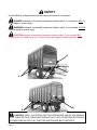
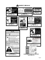
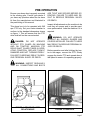
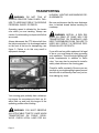
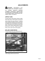
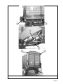
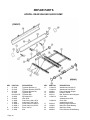
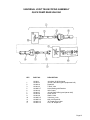
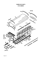
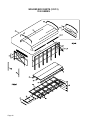
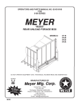
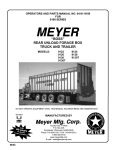
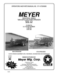
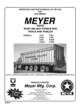
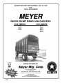
OPERATORS AND PARTS MANUAL NO. 02-1-QD
FOR
3100 & 4100 SERIES
QUICK DUMP REAR UNLOAD BOX
3100 SERIES:
3116
3118
3120
4100 SERIES
4116
4118
4120
4122
MANUFACTURED BY
COUNTY HWY. A WEST
P.O. BOX 405
DORCHESTER, WISCONSIN 54425-0405
PHONE 715-654-5132 • FAX 715-654-5513
1-800-325-9103
WWW.MEYERMFG.COM
E-MAIL: [email protected]
08-00
INTRODUCTION
Congratulations on the purchase of your new
Meyer Quick Dump Rear Unload Box. This is
the simplest, most flexible system on the
market today. With proper operation and preventative maintenance it will last for years.
This SAFETY ALERT SYMBOL
means ATTENTION! BE CAREFUL! YOUR
SAFETY IS INVOLVED! It stresses an attitude of HEADS UP FOR SAFETY. When
you see this symbol, be alert to the possibility
of PERSONAL INJURY and carefully read
the message that follows.
WARNING:
NEVER
OPERATE
WITHOUT ALL COVERS, SHIELDS AND
GUARDS IN PLACE. KEEP HANDS, FEET
AND CLOTHING AWAY FROM MOVING
PARTS. SOME COVERS AND GUARDS
HAVE BEEN REMOVED FOR ILLUSTRATIVE PURPOSES ONLY IN THIS MANUAL.
FAILURE TO HEED MAY RESULT IN SERIOUS PERSONAL INJURY OR DEATH.
At the front of this manual is a Product Registration and Inspection Certificate. Be sure
your dealer has completed this certificate
and forwarded a copy to the manufacturer to
validate the manufacturer’s warranty. The
product model and serial number are recorded on this certificate for your conve-
nience and for proper identification of your
dump box by your dealer and the manufacturer when ordering repair parts. The serial
number tag is found on the left rear drive
frame plate and is also stamped near the
PTO shaft hanger bracket on the left front upright.
All references to right hand (RH), left hand
(LH), front and rear apply to the product as
viewed looking at the rear of the box.
For information on ordering repair parts, refer to the repair parts section of this manual.
Orders must list the complete description,
correct part number, and total amount required.
You are urged to study this manual and follow the instructions carefully. Your efforts will
be repaid in better operation and service as
well as a savings in time and repair expense.
Failure to read this manual and understand
the machine could lead to serious injury. If
you do not understand instructions in this
manual, contact either your dealer or Meyer
Manufacturing Corp. at Dorchester, WI
54425.
This supercedes all previous published instructions.
Meyer Mfg. Corp. warrants new Meyer’s quick dump rear unload boxes to be free from defects in material and workmanship
under normal recommended use and service, as stated in the operator’s manual, as follows:
1. Meyer Mfg. will repair or replace F.O.B. Dorchester, WI, as Meyer Mfg. elects, any part of a new Meyer’s dump box which
is defective in material or workmanship.
a. Without charge for either parts or labor during the first year following delivery to the original retail customer, and;
b. Without charge for parts (not labor) during the second year following delivery to the original retail customer.
2. In addition to the above basic warranty, Meyer Mfg. will replace or repair, F.O.B. Dorchester, WI as Meyer’s elects;
a. Any aluminized or galvaneal painted steel panel which comprises the sides and rear of the box portion of the dump box,
upon evidence satisfactory to Meyer Mfg., that any such panels either rusted or corroded through or cracked, or split as a result of a defect in material or workmanship.
b. The warranty on aluminized and galvaneal steel panels shall apply during the first 10 years following delivery to the original retail customer.
3. Warranty forms must be completed and returned to Meyer Mfg. for this warranty to be valid.
4. This warranty is effective on all sales of Meyer dump boxes made after 1-1-1986.
5. This warranty is the sole and exclusive warranty which is applicable in connection with the manufacture and sale of this
product and Meyer Mfg. Corp. responsibility is limited accordingly.
TABLE OF CONTENTS
INTRODUCTION . . . . . . . . . . . . . . . . . . . . . . . . . . . . . . . . . . . . . 2
TABLE OF CONTENTS. . . . . . . . . . . . . . . . . . . . . . . . . . . . . . . . . . 3
SAFETY . . . . . . . . . . . . . . . . . . . . . . . . . . . . . . . . . . . . . . . . . . 4
SAFETY DECALS. . . . . . . . . . . . . . . . . . . . . . . . . . . . . . . . . . . . . 5
SAFETY PRECAUTIONS . . . . . . . . . . . . . . . . . . . . . . . . . . . . . . . . . 6
PRE-OPERATION . . . . . . . . . . . . . . . . . . . . . . . . . . . . . . . . . . . . 7
TRANSPORTING . . . . . . . . . . . . . . . . . . . . . . . . . . . . . . . . . . . . . 8
OPERATION . . . . . . . . . . . . . . . . . . . . . . . . . . . . . . . . . . . . . . . 9
ADJUSTMENTS . . . . . . . . . . . . . . . . . . . . . . . . . . . . . . . . . . . . . 11
APRON CHAIN. . . . . . . . . . . . . . . . . . . . . . . . . . . . . . . . . . . . 11
ROLLER CHAIN DRIVES . . . . . . . . . . . . . . . . . . . . . . . . . . . . . . 11
LUBRICATION. . . . . . . . . . . . . . . . . . . . . . . . . . . . . . . . . . . . . . 12
REPAIR PARTS . . . . . . . . . . . . . . . . . . . . . . . . . . . . . . . . . . . . . 14
Page 3
SAFETY
A brief definition of signal words that are used in this manual is as follows:
DANGER indicates an imminently hazardous situation which, if not avoided, WILL result in death or serious injury.
WARNING indicates a potentially hazardous situation which, if not avoided, COULD
result in death or serious injury.
CAUTION indicates a potentially hazardous situation which, if not avoided, MAY
result in minor or moderate injury. It is also used to alert against unsafe practices.
B
H
F
G
A
G
E
I
D
C (INSIDE SHIELD
CAUTION: READ ALL DECALS ON THE FORAGE BOX AND IN THIS MANUAL.
KEEP THESE DECALS CLEAN AND REPLACE ANY LOST OR DESTROYED DECALS.
BECOME FAMILIAR WITH ALL TRACTOR AND FORAGE BOX CONTROLS.
Page 4
SAFETY DECALS
DECAL A.
PART #46-0001-4
DECAL B.
PART #46-0001-12
DECAL D
PART #46-0011
DECAL C.
PART #46-0001-26
DECAL F
PART #46-0001-62
DECAL E
PART #46-0001-33
DECAL G.
PART #46-0001-20
DECAL I.
PART #46-0001-35
DECAL H.
PART #46-0001-22
ADMA SAFETY MANUAL SUPPLIED
PART #46-0013
Page 5
SAFETY PRECAUTIONS
• This equipment can be hazardous in the hands of an unfamiliar, untrained or careless operator.
• For your safety you must not operate, service, inspect or otherwise handle this equipment
unless you have read the Owner’s Manual and have been properly trained in its intended
usage.
• Require anyone who will operate this machine to read and understand this manual. Give
necessary instructions.
• Do not operate until all shields, covers and guards are in place.
• Keep hands, feet and clothing away from moving parts. Loose or floppy clothing should not
be worn by the operator.
• Make certain everyone is clear of equipment before applying power.
• Do not allow minors (or children) or inexperienced person to operate this machine.
• Always shut off power and disconnect power take-off shaft or optional Hydraulic drive sup-
ply hoses (relieve hydraulic pressure) from tractor to prevent accidental startup or unexpected movement before working on machine.
• Make sure all hydraulic fittings are tight and that all hoses are in good condition. Hydraulic
fluid escaping under pressure can have sufficient force to penetrate skin and cause serious
injury. Never investigate for hydraulic leaks by using a part of the body to feel for escaping
fluid.
• If the machine becomes clogged, shut off the tractor engine and allow all mechanisms to
stop. Disconnect power take-off shaft or optional hydraulic drive supply hoses (relieve hydraulic pressure). Then clean or work on the machine as required.
• Do not step over the power take-off shaft. Stay clear of the power take-off shaft at all times.
• Stay well clear of the rear opening discharge while operating. Pressure of the forage
against this door may cause door to open quickly and with force when latch releases.
• Do not step up on any part of the dump box at any time.
• Keep power take-off shaft telescoping tube shields turning freely. Keep power take-off master shield on tractor. Replace shields missing or damaged.
• Inspect when first delivered and regularly thereafter; that all connections and bolts are tight
and secure before operating.
• Never operate power take-off above its normal 540 RPM rating. Never connect dump box to
a 1000 RPM tractor power take-off.
• Do not tow at speeds in excess of 10 MPH.
• You must observe all applicable traffic laws when transporting on public roadways (where
legal to do so). Check local laws for all highway lighting and marking requirements.
• Always install a SMV emblem on dump box for transporting on roadways and keep this emblem clean.
FAILURE TO HEED MAY RESULT IN SERIOUS PERSONAL INJURY OR DEATH.
Page 6
PRE-OPERATION
Be sure your dump box is properly mounted
to the running gear. Consult your dealer if
you have any questions about the tie down
kit from the manufacturer and illustrated in
the parts listing of this manual.
This dump box is to be operated with 540
rpm PTO only. Set your tractor drawbar to
conform to the standard dimensions shown
on figure 1. This will ensure that the PTO
drive shaft will not be over extended.
DANGER: DO NOT OPERATE
WITHOUT PTO GUARD ON MACHINE
AND ON TRACTOR. MAINTAIN PTO
DRIVE SHAFT GUARD TUBES IN OPERATING CONDITION. REPLACE THEM IF
DAMAGED AND NOT TURNING FREELY.
FAILURE TO HEED MAY RESULT IN SERIOUS PERSONAL INJURY OR DEATH.
ARE TIGHT AND SECURE BEFORE OPERATING. FAILURE TO HEED MAY RESULT IN SERIOUS PERSONAL INJURY
OR DEATH.
Inspect all adjustments on the machine to be
sure they are proper and to provide maximum performance. Lube the machine if it is
required.
WARNING: DO NOT OPERATE
WITHOUT ALL SHIELDS, GUARDS AND
COVERS INSTALLED. FAILURE TO HEED
MAY RESULT IN SERIOUS PERSONAL INJURY OR DEATH.
Before operation and after hitching the tractor to the wagon, connect the PTO. Slowly
engage the tractor PTO and operate box at
idle speed to ensure it is operating properly.
WARNING: INSPECT REGULARLY
THAT ALL CONNECTIONS AND BOLTS
FIGURE 1. DRAWBAR & PTO
RELATIONSHIP
FIGURE 2. DUMP BOX
Page 7
TRANSPORTING
WARNING: DO NOT TOW AT
SPEEDS GREATER THAN 10 MPH. FAILURE TO HEED MAY RESULT IN SERIOUS
PERSONAL INJURY OR DEATH.
Operating speed is dictated by the terrain
over which you are traveling. Always use
caution. Avoid traveling on slopes or hills that
are unsafe.
Always disconnect the PTO drive shaft from
the tractor and return it to its storage bracket
on the front of the box for transporting, see
figure 3. Failure to do this may result in
equipment damage.
HIGHWAY LIGHTING AND MARKING REQUIREMENTS.
Be sure and observe that the rear discharge
door is latched closed before traveling on
roadways.
WARNING: INSTALL A SMV EMBLEM ON REAR OF DUMP BOX FOR
TRANSPORTING ON ROADWAYS AND
KEEP THIS EMBLEM CLEAN. FAILURE TO
HEED MAY RESULT IN SERIOUS PERSONAL INJURY OR DEATH.
If you will travel on public roads and it is legal
to do so, you must know all rules governing
such operation. This will include lighting and
brake requirements in addition to traffic
rules. You may also be required to install a
safety chain device on the running gear.
Check for traffic constantly. Be sure you can
see that no one is attempting to pass you and
that all traffic is sufficiently clear from you before making any turns.
FIGURE 3. PTO STORAGE
Your running gear probably has a telescoping tongue for convenience to hitch up. Always back up and lock this tongue in the
operating position after hitching.
WARNING: YOU MUST OBSERVE
ALL APPLICABLE TRAFFIC LAWS WHEN
TRANSPORTING ON PUBLIC ROADWAYS. CHECK LOCAL LAWS FOR ALL
Page 8
OPERATION
WARNING: MAKE CERTAIN EVERYONE IS CLEAR OF EQUIPMENT BEFORE APPLYING POWER. FAILURE TO
HEED MAY RESULT IN SERIOUS PERSONAL INJURY OR DEATH.
Pull the dump box into position.
Always park as straight ahead as possible so
there is a minimum angle on the PTO shaft
U-joints when it is connected to the tractor.
Set the brakes and shut the tractor off.
NOTE: Normal operation is using a tractor. If
using some other vehicle exercise caution
when parking and exiting this vehicle.
Remove drive shaft from the storage bracket
and connect it to the tractor PTO. Be sure the
PTO yoke is securely locked to the tractor
PTO. If using an optional hydraulic drive,
couple the hydraulic hoses to the power supply.
FIGURE 4. REAR OPENING DISCHARGE
DOOR
Make sure all persons are clear of the dump
box and the unloading area.
The rear door, figure 4, is opened automatically as forage is forced against it. The door
can spring open with extreme force when the
latches release, figure 5. This is caused by
the pressure of the forage against the door.
WARNING: DISCHARGE DOOR
CAN SPRING OPEN QUICKLY AND WITH
FORCE. KEEP ALL PERSONS WELL
CLEAR OF THE DUMP BOX AND UNLOADING AREA. FAILURE TO HEED MAY
RESULT IN SERIOUS PERSONAL INJURY
OR DEATH.
FIGURE 5. DOOR LATCH
(Typical both sides)
Page 9
Return to the tractor, restart, and slowly engage the PTO to start the apron chains and
open the rear door. Once the door opens,
regulate the discharge flow with the tractor
PTO speed (or tractor hydraulic flow control
for hydraulic driven). Do not operate above
rated speed of 540 RPM.
WARNING: DO NOT STEP UP ON
ANY PART OF THE DUMP BOX AT ANY
TIME. FAILURE TO HEED MAY RESULT IN
SERIOUS PERSONAL INJURY OR
DEATH.
Unloading is best observed from the tractor
seat. If you are at ground level, the front of
the box has a top section of expanded metal
for convenient observation.
When finished unloading reduce speed to
idle and disengage the PTO drive. Pull the
dump box straight ahead to pull the door
away from the unloaded pile of forage. When
free gravity will allow the door to swing shut
and the door latches will engage the apron
chain links to secure it shut. Observe that this
happens properly. Set the brakes and turn
the tractor “OFF”. When all movement has
stopped, disconnect the PTO drive shaft
from the tractor and return it to its storage
bracket. Secure it with the rubber tie down
strap.
WARNING: DO NOT STEP OVER
THE POWER TAKE-OFF SHAFT. STAY
CLEAR OF POWER TAKE-OFF SHAFT AT
ALL TIMES. FAILURE TO HEED MAY RESULT IN SERIOUS PERSONAL INJURY
OR DEATH.
The unloading process described is to be accomplished by the operator alone. This will
eliminate unexpected startups and minimize
other hazards that can result by more than
one person in control. If the dump box bePage 10
comes clogged, shut off all power to the
dump box. Wait for all motion to stop. Disconnect PTO shaft or hydraulic supply
hoses. Then clean out machine. Never use
power to aid clean out. If any mechanism
fails, remove dump box to safe work area
and repair the mechanism before proceeding
with unloading.
DANGER: NEVER ENTER THE
DUMP BOX WITHOUT FIRST DISCONNECTING PTO SHAFT FROM POWER
SUPPLY OR DISCONNECTING OPTIONAL
HYDRAULIC HOSES FROM POWER
SUPPLY. FAILURE TO HEED MAY RESULT IN SERIOUS PERSONAL INJURY
OR DEATH.
Never enter the dump box for any reason if
there is any possibility of power being applied to the unit.
WARNING: DISCONNECT PTO
DRIVE SHAFT (OR OPTIONAL HYDRAULIC
POWER
SOURCE)
BEFORE
CLEANING, ADJUSTING, LUBRICATING
OR SERVICING THIS MACHINE. FAILURE
TO HEED MAY RESULT IN SERIOUS PERSONAL INJURY OR DEATH.
Allow box to completely clean out the last
load of forage. It is recommended to lube the
dump box before storage to exclude moisture from bearings. Apply oil to roller chain
drives and to the apron chains. It is also a
good time to inspect all adjustments and
check for parts that need repair or replacement. Performing these tasks now will guarantee that the box is ready for use at the
beginning of the next season.
ADJUSTMENTS
WARNING: DISCONNECT PTO
DRIVE SHAFT (OR OPTIONAL HYDRAULIC
POWER
SOURCE)
BEFORE
CLEANING, ADJUSTING, LUBRICATING
OR SERVICING THIS MACHINE. FAILURE
TO HEED MAY RESULT IN SERIOUS PERSONAL INJURY OR DEATH.
APRON CHAIN
Correct tension on the apron chains is when
about three feet of chain does not touch the
return slides at the rear of the box. To tighten
chains, tighten the adjuster bolts at each end
and center of the front sprocket shaft, see figure 6. Each apron chain has its own sprocket
shaft. At the center cutout there is an adjuster bolt for each shaft. Tighten the adjuster
bolts at each end of each shaft equally.
ROLLER CHAIN DRIVES
The roller chain drives are tensioned by auto-
ADJUSTER
BOLTS
FIGURE 6. ADJUST APRON CHAINS
matic spring loaded tension blocks.
Page 11
LUBRICATION
WARNING: DISCONNECT PTO DRIVE
SHAFT (OR OPTIONAL HYDRAULIC
POWER SOURCE) BEFORE CLEANING,
ADJUSTING, LUBRICATING OR SERVICING THIS MACHINE. FAILURE TO
HEED MAY RESULT IN SERIOUS PERSONAL INJURY OR DEATH.
Grease (2) Pto drive shaft joints daily.
Maintain oil in gearbox to centerline of
shafts. Use Multi purpose 80-90 transmission lube. Lighter oil may be used in temperatures lower than 20 degrees.
Grease the (3) main apron drive shaft
bearing at rear, weekly.
Grease jackshaft at rear, weekly.
Use light machine oil periodically on
the roller chain drives, weekly.
Grease (2) door hinges annually.
Page 12
FIGURE 7. LUBRICATION DIAGRAM
Page 13
REPAIR PARTS
APRON - REAR UNLOAD QUICK DUMP
KEY
1
2
3
4
5
6
7
8
10
PART NO.
25-0146
25-0145
25-0144
25-0147
830-5013-6Z
10-0054
23-0043
11-0098
11-0085
11-0068-3
11-0008-1
11-0008-2
11-0080
Page 14
DESCRIPTION
Tightener Bracket LH
Tightener Bracket CENTER
Tightener Bracket RH
Tightener Nut
Tightener Bolt
Sprocket #67-6
Idler Shaft
Chain Assy (20ft.) 667X
Chain Assy (18ft.) 667X
Pintle Chain Link-D667H
Pintle Chain Link D667X
Rivet, 3/8x7/8
Slat
KEY
11
12
13
15
16
PART NO.
11-0068-2
11-0008-3
24-0091
24-0090
25-0141
11-0081-2
11-0084-2
17
18
20
23
25-0018
14-0009
23-0050
49-0006
DESCRIPTION
Attachment Link-D667H
Attachment Link-D667X
Front Shield with Hinges
Deflector Shield
Brkt, Deflector Shield Support
Chain Slat
w/attachments-667H
Chain Slat
w/attachments-667X
Bearing Support Bracket
Main Drive Shaft Bearing
Main Drive Shaft
Front Deflector Shield Belting
UNIVERSAL JOINT TELESCOPING ASSEMBLY
QUICK DUMP REAR UNLOAD
KEY
PART NO.
DESCRIPTION
1
2
3
5
6
7
8
9
10
11
16
17
18-0014
18-0014-1
18-0001-4
18-0014-3
18-0005-17
18-0014-6
18-0014-7
18-0014-8
18-0014-9
18-0005-15
18-0005-16
18-0001-13
18-0001-14
Joint Assy, W-90 Universal
Joint & Tube Half w/guard (implement half)
Repair Kit
Tube & Yoke
Nylon Bearing with Retainer
Inner Guard
Joint & Shaft Half w/guard (tractor half)
Outer Guard
Shaft & Yoke
Yoke Assy, Lock
Quik Lok Repair Kit
“W” Repair Kit w/2 pins
Pins, “W” Repair Kit
Page 15
DRIVE TRAIN
QUICK DUMP REAR UNLOAD
(REAR)
(FRONT)
Page 16
KEY
PART NO.
DESCRIPTION
1
2
3
4
6
7
8
24-0105-3
24-0105-2
24-0105-1
14-0003-2
14-0002-3
14-0003-1
23-0036
23-0035
23-0042
100-9990-20
37-0007
19-0016
100-9990-21
23-0037
23-0041
23-0049
910-0003
911-0004
10-0065
901-3618-6
929-3601
811-3118-3Z
11-0041
10-0062
25-0176
100-9990-22
25-0196-3
25-0195-3
25-0194
914-3602
24-0106-5
25-0196-4
24-0106
PTO Belting 6"x14"
PTO Belting 6"x10"
PTO Shield
1-1/4 Two Bolt Flange
1-1/4 Bearing w/Lock Collar
1-1/4 Pillow Block Flange
Main Drive Shaft 16ft.
Main Drive Shaft 18ft.
Main Drive Shaft 20ft.
PVC Pipe Guard 72"
Shaft Coupler
Right Angle Gearbox
PVC Pipe Guard 30-1/2"
Cross Drive Shaft 42-3/8"
Idler Shaft Weldment
Output Shaft
80B45 Sprocket
80-62 Roller Chain
Sprkt Wldt 80A12/60A48
Wood Tightener Block
Spring
Eye Bolt
60-66 Roller Chain
60B15 Sprocket
Support Arm
Idler Shaft Bolt w/Zerk
Idler Tightener Weldment
Drive Tightener Weldment
Spring Tightener Angle
Four Bolt Flange Bearing 1-1/2"
Rear Shield Frame
Tightener Catch
Cluster Shield
9
10
11
12
13
14
15
16
17
18
19
20
21
22
23
27
28
29
30
32
33
34
35
36
Page 17
TIE DOWN KIT FOR STEEL BOX
Page 18
KEY
PART NO.
DESCRIPTION
1
2
3
4
5
6
7
8
52-0003S
25-0084
52-0003-1
801-3816-1.5Z
805-0038-Z
815-3816-Z
801-5013-1.25-Z
805-0050-Z
815-5013-Z
Tie Down Kit (Steel Stringers)
Bracket
Chain
Bolt, Hex Machine-3/8x1-1/2
3/8 Flat Washer
3/8 Lock Nut
Hex Machine Bolt 4 1/2x1-1/4
1/2 Flat Washers
1/2 Lock Nuts
REAR DISCHARGE DOOR COMPONENTS
KEY
PART NO.
DESCRIPTION
1
2
3
4
5
6
7
8
9
25-0179
25-0190-1
100-9990-23
100-9990-25-12
100-9990-25-13
33-1002
100-9990-25-13
100-9990-24
25-0191-1
Bearing Bracket Brace
Left Main Roller Bracket
Left Gate Side Frame
Latch Catch
Back Gate Frame
Slow Moving Vehicle Bracket
Back Gate Panel 40-3/4x84-1/4
Right Gate Side Frame
Right Main Roller Bracket
Page 19
DUMP BOX PARTS
4100 SERIES
(REAR)
(FRONT)
Page 20
KEY
PART NO.
DESCRIPTION
1
100-9990-53
100-9990-8-7
100-9990-15-4
31-0006-2
100-9990-17-6
100-9990-8-2
100-9990-8-1
100-9990-8-6
100-9990-8-5
100-9990-8-4
100-9990-8-3
100-9990-53
100-9990-10
100-9990-51-1
100-9990-15-8
100-9990-26
100-9990-26-5
100-9990-61
100-9990-60
100-9990-69
100-9990-63-1
100-9990-70
100-9990-62-1
100-9990-31
100-9990-14-3
100-9990-54
100-9990-9
100-9990-55
100-9990-8
100-9990-15-1
100-9990-50
100-9990-56
100-9990-1-4
100-9990-1-5
100-9990-50-1
100-9990-1-1
100-9990-32
100-9990-52-1
100-9990-8-8
25-0006
100-9990-28
100-9990-27
100-9990-33
100-9999-39
100-9999-38
100-9999-39
100-9999-38
100-9990-1-10
20’ Side Panel, 20 Ga x40-3/4 Painted
18’ Side Panel, 20 Ga x40-3/4 Painted
Back Roof Panel
Panel, Expanded Metal
20 Ga Front End Gate Panel Painted
Rear Left, Upright, 10 Ga x82-1/2 (illustrated)
Rear Right, Upright, 10 Ga x82-1/2 (not illustrated)
Center Left, Upright, 10 Ga x82-1/2 (illustrated)
Center Right, Upright, 10 Ga x82-1/2 (not illustrated)
Front Left, Upright, 10 Ga x82-1/2 (illustrated)
Front Right, Upright, 10 Ga x82-1/2 (not illustrated)
Floor Complete 20ft.
Floor Complete 18ft.
Roof Panel Painted 21’3"
Roof Panel Painted 19’3"
Front End Gate, Complete
Front End Gate, Frame Only
Roof Angle Left (illustrated)
Roof Angle Right (not illustrated)
Left Roof Angle Ext. 20’ (illustrated)
Left Roof Angle Ext. 18’ (illustrated)
Right Roof Angle Ext. 20’ (not illustrated)
Right Roof Angle Ext. 18’ (not illustrated)
Back Gate Panel Angle
Roof Guard Strap
Left Side, Complete 20’ (illustrated)
Left Side, Complete 18’ (illustrated)
Right Side, Complete 20’ (not illustrated)
Right Side, Complete 18’ (not illustrated)
Roof Bow
Bottom Frame, Complete 20’
Bottom Frame, Complete 18’
Back Cross Channel 94-1/2 w/Gussets
Cross Channels 94-1/2 w/Gussets
10" Channel Bed Piece (19’-10")
10" Channel Bed Piece (17’-10")
Side End Gate Cap Right
Top Rail 20’ TSS Side
Top Rail 18’ TSS Side
PTO Hanger Bracket
Right Front Roof Support Bracket
Left Front Roof Support Bracket
Side End Gate Cap Left
3" Side Channel Suport
Main Stringer Support
3" Side Channel Support (14’ & 16’ Floor Lengths)
Main Stringer -Support
Rear Steel Stringer, Reinforcing Plate
(18’+ Floor Lengths)
2
3
4
5
6
7
8
9
10
11
12
13
14
15
16
17
18
19
20
21
22
23
24
25
26
27
28
29
30
31
32
33
34
35
36
37
38
Page 21
WELDED BOX PARTS (1 OF 2)
3100 SERIES
Page 22
KEY
PART NO.
DESCRIPTION
1
100-9995-19
100-9995-18
100-9995-17
100-9995-120-1
14’ Side Panel, 20 Ga x40-3/4 Aluminized
16’ Side Panel, 20 Ga x40-3/4 Aluminized
18’ Side Panel, 20 Ga x40-3/4 Aluminized
Back Roof Panel, 20-3/8x86 Aluminized
100-9990-8-2
2
3
4
5
6
100-9990-8-1
7
100-9990-8-6
8
100-9990-8-5
9
100-9990-8-4
10
100-9990-8-3
11
100-9990-12
100-9990-11
100-9990-10
100-9990-13-2
100-9990-14-2
100-9990-15-8
Rear Left, Upright, 10 Ga x 82-1/2"
(illustrated)
Front Right, Upright, 10 Ga x 82-1/2"
(not illustrated)
Center Left, Upright, 10Ga x 82-1/2"
(illustrated)
Center Right, Upright, 10 Ga x 82-1/2"
(not illustrated)
Front Left, Upright, 10 Ga x 82-1/2"
(illustrated)
Front Right, Upright, 10 Ga x 82-1/2"
(not illustrated)
Floor Complete 14’
Floor Complete 16’
Floor Complete 18’
Roof Panel Painted 15’ 3"
Roof Panel Painted 17’ 3"
Roof Panel Painted 19’ 3"
100-9990-61
100-9990-60
100-9990-67-1
100-9990-65-1
100-9990-63-1
100-9990-66-1
100-9990-64-1
100-9990-62-1
100-9990-15-9
100-9990-14-3
100-9994-4
100-9994-6
100-9994-8
100-9994-5
100-9994-7
100-9994-9
100-9990-15-1
100-9994-1
100-9994-2
100-9994-3
100-9990-1-3
100-9994-1-3
Roof Angle Left (illustrated)
Roof Angle Right (not illustrated)
Left Roof Angle Ext. 14’ (illustrated)
Left Roof Angle Ext. 16’ (illustrated)
Left Roof Angle Ext. 18’ (illustrated)
Right Roof Angle Ext. 14’ (not illustrated)
Right Roof Angle Ext. 16’ (not illustrated)
Right Roof Angle Ext. 18’ (not illustrated)
Back Gate Panel Angle
Roof Guard Strap
Left Side, Complete 14’ (illustrated)
Left Side, Complete 16’ (illustrated)
Left Side, Complete 18’ (illustrated)
Right Side, Complete 14’ (not illustrated)
Right Side, Complete 16’ (not illustrated)
Right Side, Complete 18’ (not illustrated)
Roof Bow
Bottom Frame, Complete 14’
Bottom Frame, Complete 16’
Bottom Frame, Complete 18’
Back Cross Channel 94-1/2"
Back Cross Channel Gusset
12
13
14
15
16
17
18
19
20
21
22
23
24
25
Page 23
WELDED BOX PARTS (2 OF 2)
3100 SERIES
Page 24
KEY
PART NO.
DESCRIPTION
26
100-9990-1-2
100-9994-1-1
100-9990-3-1
100-9990-2-1
100-9990-1-1
100-9990-4-2
100-9990-6-2
100-9990-8-8
100-9999-39
100-9994-1-2
100-9999-2-3
100-9998-7
100-9998-8
100-9999-5
Cross Channel 94-1/2"
Cross Channel Gusset
10" Channel Bed Piece (13’-10")
10" Channel Bed Piece (15’-10")
10" Channel Bed Piece (17’-10")
Side End Gate Cap
Top Rail 14’
Top Rail 16’
Top Rail 18’
Stringer Support Channel
Stringer Support Cross Angle
Cross Channel Center U Piece
14’ Chain Slide
16’ Chain Slide
18’ Chain Slide
100-9995-120
100-9997-1
100-9997-2
100-9999-6
100-9998-9
100-9998-10
100-9999-7
100-9994-1-5
100-9995-133
100-9995-134
100-9995-135
Rear Roof Assy Complete
Center Floor Support, 2x6x14’
Center Floor Support, 2x6x16’
Center Floor Support, 2x6x18’
Outer Floor Support 3x6x14’
Outer Floor Support 3x6x16’
Outer Floor Support 3x6x18’
Chain Rail Tab
3514 Roof Assy., Complete
3516 Roof Assy., Complete
3518 Roof Assy., Complete
27
28
29
30
31
32
33
34
35
36
37
38
39
Page 25
Page 26
Page 27