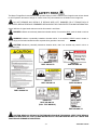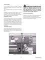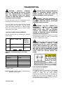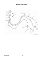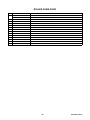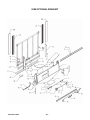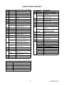
1
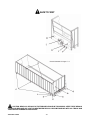
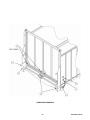
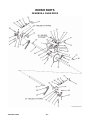
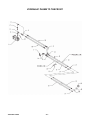
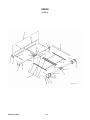
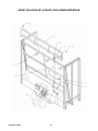
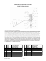
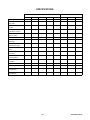
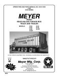
OPERATOR’S AND PARTS MANUAL NO. PB-9100
FOR
9100 SERIES
MEYER
“BOSS”
REAR UNLOAD FORAGE BOX
TRUCK AND TRAILER
MODELS:
9122
9126
9130
9136T
9124
9128
9130T
9140T
DO NOT OPERATE EQUIPMENT UNTIL THIS MANUAL HAS BEEN READ AND UNDERSTOOD.
MANUFACTURED BY
Meyer Mfg. Corp.
6990633 (1-13)
06/2014
County Hwy. A West
P.O. Box 405
Dorchester, Wisconsin 54425-0405
Phone 715-654-5132 • FAX 715-654-5513
1-800-325-9103
www.meyermfg.com
E-mail: [email protected]
Printed in U.S.A.
© Bobcat Company 2013
INTRODUCTION
Congratulations on your purchase of a new Meyer
Rear Unload Forage Box. Undoubtedly you have
given much consideration to your purchase and we’re
proud that you have selected Meyer. Pride in
craftsmanship, engineering and customer service
have made Meyer products the finest in the farm
equipment industry today.
There is no substitute for quality. That is why
thousands of people like you have purchased Meyer
farm equipment. They felt it was the best equipment to
serve their farming needs, now and in years to come.
We ask that you follow our policy of “safety first,” and
we strongly suggest that you read through the owner’s
manual before operating your Meyer farm equipment.
Meyer Manufacturing Corporation wants to thank you
for not compromising quality. We are determined to
offer excellence in customer service as well as
provide you with the very best value for your dollar.
Sincerely,
All Employees of
MEYER MANUFACTURING CORPORATION
The Model 9100 is available as a truck/trailer mounted
unit or mounted to a wagon running gear pulled and
powered by a farm tractor. When the PTO is referred
to, it means power takeoff from the truck.
The Model 9100 may be referred to as rear unload
box, forage box, box or rear unload forage box in this
manual.
Meyer Manufacturing Corporation reserves the right to
make improvements in design, or changes in
specifications at any time, without incurring any
obligation to owners of units previously sold.
This supersedes all previous published instructions.
IMPORTANT:
At the front of this manual is a Product Registration
and Inspection Certificate. Be sure your dealer has
completed this certificate and promptly forwarded a
copy to Meyer Manufacturing to validate the
manufacturer’s warranty. The product model and
serial number are recorded on this certificate and
below for proper identification of your Meyer Forage
Box by your dealer and the manufacturer when
ordering repair parts. The serial number plate is found
near the control levers on your forage box and
stamped in the front corner of the left hand end frame.
Model No.
Serial No.
Date of Purchase
At the back of this manual is the repair parts section.
All replacement parts are to be obtained from or
ordered through your Meyer dealership. When
ordering repair parts, refer to the parts section and
give complete information including quantity, correct
part number, detailed description and even Model No.
and Serial No. of the forage box which needs repair
parts.
HOW TO READ YOUR SERIAL NUMBER
This SAFETY ALERT SYMBOL means
ATTENTION! BE CAREFUL! YOUR SAFETY IS
INVOLVED! It stresses an attitude of HEADS UP FOR
SAFETY. When you see this symbol, be alert to the
possibility of PERSONAL INJURY and carefully read
the message that follows.
WARNING: NEVER OPERATE WITHOUT
ALL COVERS, SHIELDS AND GUARDS IN PLACE.
KEEP HANDS, FEET AND CLOTHING AWAY
FROM MOVING PARTS. SOME COVERS AND
GUARDS
HAVE
BEEN
REMOVED
FOR
ILLUSTRATIVE PURPOSES ONLY IN THIS
MANUAL. FAILURE TO HEED MAY RESULT IN
SERIOUS PERSONAL INJURY OR DEATH.
9100 Rear Unload
Your serial number is stamped on the front left hand
vertical tube.
Example: 1291253
Model Year / Model / Sequence of Build
12
91
253
NOTE: All references to right hand (RH), left hand
(LH), front and rear apply to the product as viewed
from the rear of the box.
You are urged to study this manual and follow the
instructions carefully. Your efforts will be repaid in
better operation and service as well as a savings in
time and repair expense. Failure to read this manual
and understand the machine could lead to serious
injury. If you do not understand instructions in this
manual, contact either your dealer or Meyer
Manufacturing Corp. at Dorchester, WI 54425.
-2-
PRE-DELIVERY & DELIVERY CHECK LIST
8100 / 9100 Check List
Meyer Manufacturing Corporation
Phone: 715-654-5132 • Toll-Free: 1-800-325-9103 • P.O. Box 405 • Dorchester, WI 54425
This Pre-Delivery & Delivery Check List must be gone through by the Selling Party and the Customer to
validate the Owner’s Registration Form.
PRE-DELIVERY CHECK LIST
DELIVERY CHECK LIST
After the New Meyer Forage Box has been completely
set-up, check to be certain it is in correct running order
before delivering it to the customer.
The following check list is an important reminder of
valuable information that MUST be passed on to the
customer at the time the unit is delivered.
The following is a list of points to inspect:
Check off each item as you explain it to the
customer.
Check off each item as you have made the proper
adjustments and found the item operating
satisfactorily. Any adjustments made, MUST be
according to specifications defined in this manual.
All shields and guards are in place and securely
fastened.
All bolts and other fasteners are secure and tight.
All mechanisms operate trouble free.
All grease fittings have been lubricated, gear
boxes filled to proper levels, and all roller chains
are oiled. See “Lubrication” section of this
manual.
Main Apron Chains are at proper tension. See
“Adjustments” section in this manual.
All decals are in place and legible.
Explain to the customer that pre-delivery check
list was fully completed.
Give customer the Owner & Operator’s Manual.
Instruct to read and completely understand its
contents BEFORE attempting to operate the
Forage Box.
Explain and review with customer the New Meyer
Forage Box manufacturer’s warranty.
Show the customer where to find the serial
number on the implement.
Explain and review with the customer “Safety
Precautions” section of this manual.
Explain and review with customer the proper
“Start-up and Operating Procedures” sections of
this manual.
Demonstrate the start-up & shutdown controls,
proper hydraulic hose storage and tip holder
used to keep system clean from contaminants.
Explain that regular lubrication and proper
adjustments are required for continued proper
operation and long life of the Forage Box. Review
with the customer the “Lubrication” and
“Adjustments” sections of this manual.
Explain the importance of apron chain tension,
and the need to watch and tighten during the
break in period.
Fully complete this “PRE-DELIVERY
DELIVERY CHECK LIST” with the customer.
-3-
&
9100 Rear Unload
Meyer Manufacturing Corporation
574 West Center Avenue
Dorchester, WI 54425
Phone. 1-800-325-9103
Fax: 715-654-5513
Email: [email protected]
Website: www.meyermfg.com
9100 Rear Unload
-4-
TABLE OF CONTENTS
INTRODUCTION . . . . . . . . . . . . . . . . . . . . . . . . . . . . . . . . . . . . . . . . . . . . . . . . . . . . . . . . . . . . . . . . 2
HOW TO READ YOUR SERIAL NUMBER . . . . . . . . . . . . . . . . . . . . . . . . . . . . . . . . . . . . 2
PRE-DELIVERY & DELIVERY CHECK LIST . . . . . . . . . . . . . . . . . . . . . . . . . . . . . . . . . . . . . . . . . . . 3
MANUFACTURER’S WARRANTY . . . . . . . . . . . . . . . . . . . . . . . . . . . . . . . . . . . . . . . . . . . . . . . . . . 6
SAFETY PRECAUTIONS . . . . . . . . . . . . . . . . . . . . . . . . . . . . . . . . . . . . . . . . . . . . . . . . . . . . . . . . . 7
SAFETY FIRST . . . . . . . . . . . . . . . . . . . . . . . . . . . . . . . . . . . . . . . . . . . . . . . . . . . . . . . . . . . . . 8
PRE-OPERATION . . . . . . . . . . . . . . . . . . . . . . . . . . . . . . . . . . . . . . . . . . . . . . . . . . . . . . . . . . . . . . 10
GENERAL . . . . . . . . . . . . . . . . . . . . . . . . . . . . . . . . . . . . . . . . . . . . . . . . . . . . . . . . . . . . 10
LIGHT HOOKUP . . . . . . . . . . . . . . . . . . . . . . . . . . . . . . . . . . . . . . . . . . . . . . . . . . . . . . . 11
HYDRAULIC HOOKUP . . . . . . . . . . . . . . . . . . . . . . . . . . . . . . . . . . . . . . . . . . . . . . . . . . 11
AIR BRAKE HOOKUP . . . . . . . . . . . . . . . . . . . . . . . . . . . . . . . . . . . . . . . . . . . . . . . . . . . 11
START UP AND STOPPING . . . . . . . . . . . . . . . . . . . . . . . . . . . . . . . . . . . . . . . . . . . . . . 11
TRANSPORTING . . . . . . . . . . . . . . . . . . . . . . . . . . . . . . . . . . . . . . . . . . . . . . . . . . . . . . . . . . . . . . . 12
TRACTOR TOWING SIZE REQUIREMENTS . . . . . . . . . . . . . . . . . . . . . . . . . . . . . . . . . 12
MATERIAL ESTIMATED WEIGHT PER CUBIC FOOT . . . . . . . . . . . . . . . . . . . . . . . . . . 12
9100 TRAILER REAR BUMPER . . . . . . . . . . . . . . . . . . . . . . . . . . . . . . . . . . . . . . . . . . . 12
REAR UNLOAD OPERATION . . . . . . . . . . . . . . . . . . . . . . . . . . . . . . . . . . . . . . . . . . . . . 13
LUBRICATION . . . . . . . . . . . . . . . . . . . . . . . . . . . . . . . . . . . . . . . . . . . . . . . . . . . . . . . . . . . . . . . . . 16
DAILY LUBRICATION . . . . . . . . . . . . . . . . . . . . . . . . . . . . . . . . . . . . . . . . . . . . . . . . . . . 16
END OF CROP CLEANUP AND MAINTENANCE . . . . . . . . . . . . . . . . . . . . . . . . . . . . . 16
ADJUSTMENTS . . . . . . . . . . . . . . . . . . . . . . . . . . . . . . . . . . . . . . . . . . . . . . . . . . . . . . . . . . . . . . . . 18
REPAIR PARTS . . . . . . . . . . . . . . . . . . . . . . . . . . . . . . . . . . . . . . . . . . . . . . . . . . . . . . . . . . . . . . . . 20
GEARBOX & CHAIN DRIVE . . . . . . . . . . . . . . . . . . . . . . . . . . . . . . . . . . . . . . . . . . . . . . . . . . 20
HYDRAULIC PLUMB TO THE FRONT . . . . . . . . . . . . . . . . . . . . . . . . . . . . . . . . . . . . . . . . . . 22
APRON . . . . . . . . . . . . . . . . . . . . . . . . . . . . . . . . . . . . . . . . . . . . . . . . . . . . . . . . . . . . . . . . . . 24
9100 MAIN BODY . . . . . . . . . . . . . . . . . . . . . . . . . . . . . . . . . . . . . . . . . . . . . . . . . . . . . . . . . . 28
FRONT AIR HOOK-UP & FRONT FOLD DOWN EXTENSION . . . . . . . . . . . . . . . . . . . . . . . 34
REAR DOOR . . . . . . . . . . . . . . . . . . . . . . . . . . . . . . . . . . . . . . . . . . . . . . . . . . . . . . . . . . . . . . 36
OPTIONAL DOUBLE DOOR . . . . . . . . . . . . . . . . . . . . . . . . . . . . . . . . . . . . . . . . . . . . . . . . . . 38
HIGHWAY TRANSPORT LIGHTS . . . . . . . . . . . . . . . . . . . . . . . . . . . . . . . . . . . . . . . . . . . . . . 40
TRAILER LIGHTING . . . . . . . . . . . . . . . . . . . . . . . . . . . . . . . . . . . . . . . . . . . . . . . . . . . . . . . . 42
TRAILER SUSPENSION . . . . . . . . . . . . . . . . . . . . . . . . . . . . . . . . . . . . . . . . . . . . . . . . . . . . . 44
WHEEL END PARTS . . . . . . . . . . . . . . . . . . . . . . . . . . . . . . . . . . . . . . . . . . . . . . . . . . . . . . . . 46
ROLLER CHAIN OILER . . . . . . . . . . . . . . . . . . . . . . . . . . . . . . . . . . . . . . . . . . . . . . . . . . . . . . 48
9100 OPTIONAL GRAIN KIT . . . . . . . . . . . . . . . . . . . . . . . . . . . . . . . . . . . . . . . . . . . . . . . . . . 50
GATE DELAY/RETURN LINE . . . . . . . . . . . . . . . . . . . . . . . . . . . . . . . . . . . . . . . . . . . . . . . . . 52
8100-GDS-SM & 8100-GDS-SME . . . . . . . . . . . . . . . . . . . . . . . . . . . . . . . . . . . . . . . . . . . . . . 54
GATE DELAY PACKAGE W/SIDE MOUNT CONTROL . . . . . . . . . . . . . . . . . . . . . . . . . . . . . 54
GATE DELAY PACKAGE 8100-GDS . . . . . . . . . . . . . . . . . . . . . . . . . . . . . . . . . . . . . . . . . . . 56
9100 TRAILER TIRE WHEEL TORQUE . . . . . . . . . . . . . . . . . . . . . . . . . . . . . . . . . . . . . . . . . 57
WHEEL TORQUE TABLE . . . . . . . . . . . . . . . . . . . . . . . . . . . . . . . . . . . . . . . . . . . . . . . . . . . . 57
TIRE INFLATION . . . . . . . . . . . . . . . . . . . . . . . . . . . . . . . . . . . . . . . . . . . . . . . . . . . . . . . . . . . 57
SPECIFICATIONS . . . . . . . . . . . . . . . . . . . . . . . . . . . . . . . . . . . . . . . . . . . . . . . . . . . . . . . . . . 58
MAINTENANCE RECORD . . . . . . . . . . . . . . . . . . . . . . . . . . . . . . . . . . . . . . . . . . . . . . . . . . . . . . . . 62
-5-
9100 Rear Unload
MANUFACTURER’S WARRANTY
NEW MEYER REAR UNLOADFORAGE BOX
01/01/00
I.
The “Product Registration & Inspection Certificate” along with the original billing invoice “Owners
Registration Form” must be completed in full and promptly returned to Meyer Mfg. Corp. for this
warranty to become both valid and effective. All warranties on New Meyer Forage Boxes shall apply
only to the original retail customer from an authorized Meyer Mfg. Corp. dealership.
II.
This warranty shall not apply to any Meyer Forage Box which has been subjected to misuse,
negligence, alteration, accident, incorrect operating procedures, or which shall have been repaired with
parts other than those obtained through Meyer Mfg. Corp.
III.
Meyer Mfg. Corp. warrants New Meyer Forage Boxes to be free from defects in material and
workmanship under recommended use and maintenance service, as stated in the Operator’s and Parts
Manual, as follows:
A.
Meyer Mfg. Corp. will repair or replace F.O.B. Dorchester, WI, as Meyer Mfg. Corp. elects,
any part of a new Meyer Forage Box which is defective in material or workmanship:
1. Without charge for either parts or labor during the first (1) year from purchase date
to the original retail customer.
2. Without charge for parts only during the second (2) year from purchase date to the
original retail customer.
B.
In addition to the above basic warranty, Meyer Mfg. Corp. will repair or replace F.O.B.
Dorchester, WI as Meyer Mfg. Corp. elects:
1. Any part of the following which is defective in material or workmanship (not neglect
to recommended use and service) without charge for parts only (not labor) during
the stated time periods from date of purchase to the original retail customer:
Two (2) Years:
The D667XH pintle main apron chain assembly.
2. Any part of the following which is defective in material or workmanship (not neglect
to recommended use and service) with a “pro-rated” charge for parts only (not labor)
during the stated time period from date of purchase to the original retail customer:
Ten (10) Years:
a. The all welded steel frame box structure.
IV.
COMMERCIAL USE: Coverage as in paragraph III.A.1. ONLY, except warranty coverage is for (90) days
for parts and labor to the original commercial retail customer.
V.
Repairs eligible for labor warranty must be made by Meyer Mfg. Corp. or an authorized Meyer dealership.
The original retail customer is responsible for the transportation of the forage box to the dealership for
warranty service or for any service call expenses.
VI.
Except as stated above, Meyer Mfg. Corp. shall not be liable for injuries or damages of any kind or nature,
direct, consequential, or contingent, to persons or property. This warranty does not extend to loss of crop
or for any other reasons.
VII.
No person is authorized to give any other warranties or to assume any other obligation on Meyer Mfg.
Corp.’s. behalf unless made or assumed in writing by Meyer Mfg. Corp. This warranty is the sole and
exclusive warranty which is applicable in connection with the manufacture and sale of this product and
Meyer Mfg. Corp.’s responsibility is limited accordingly.
Optional Equipment-Tarp, Scales Etc. Warranty-See Original Equipment Manufacturer's Warranty.
9100 Rear Unload
-6-
SAFETY PRECAUTIONS
THIS SYMBOL IS USED TO CALL
ATTENTION TO INSTRUCTIONS CONCERNING
PERSONAL SAFETY. BE SURE TO OBSERVE
AND FOLLOW THESE INSTRUCTIONS. TAKE
TIME TO BE CAREFUL!
Observe all applicable traffic laws when transporting
on public roadways (where legal to do so). Check
local laws for all highway lighting and marking
requirements.
Tractor Models: Always install a SMV emblem on
forage box for transporting on roadways and keep this
emblem clean and bright.
WARNING: BEFORE ATTEMPTING TO
OPERATE THIS FORAGE BOX, READ AND STUDY
THE FOLLOWING SAFETY INFORMATION. IN
ADDITION, MAKE SURE THAT EVERY INDIVIDUAL
WHO OPERATES OR WORKS WITH THE FORAGE
BOX,
WHETHER
FAMILY
MEMBER
OR
EMPLOYEE, IS FAMILIAR WITH THESE SAFETY
PRECAUTIONS.
Keep the forage box away from power lines. Contact
with electric lines may result in serious injury or death
by electrocution!
Require anyone who will operate this forage box to
read and completely understand this owner’s manual.
Give necessary instructions.
Always shut off the power, remove keys, keep keys in
your possession to prevent accidental startup or
unexpected movement before working on forage box.
DO NOT operate, service, inspect or otherwise handle
this forage box until all operators have read this
Owner’s Manual and have been properly trained in its
intended usage.
Tractor Models: DO NOT tow at speeds in excess of
20 MPH when transporting this forage box. Never
exceed a safe travel speed.
DO NOT allow minors (children) or inexperienced
persons to operate this forage box.
DO NOT clean, adjust or lubricate while the forage
box is in motion.
DO NOT clean, adjust or reset the emergency stop
while the forage box is in motion.
Inspect when first delivered and regularly thereafter;
that all connections and bolts are tight and secure
before operating.
If the forage box becomes clogged, shut off the
power, set park brake, remove keys, keep keys in
your possession, and allow all mechanism to stop.
Then, clean or work on the forage box as required.
Always install a SMV emblem on forage box for
transporting on roadways and keep this emblem clean
and bright.
MEYER MFG. CORP. PROVIDES GUARDS FOR
EXPOSED
MOVING
PARTS
FOR
THE
OPERATOR’S PROTECTION; HOWEVER, SOME
AREAS CAN NOT BE GUARDED OR SHIELDED IN
ORDER TO ASSURE PROPER OPERATION. THE
OPERATOR’S MANUAL AND DECALS ON THE
FORAGE BOX ITSELF WARN YOU OF DANGERS
AND MUST BE READ AND OBSERVED CLOSELY!
Know how to stop the unloading unit of the forage box
before starting it!
Study the Above Safety Rules
DO NOT operate until all shields and guards are in
place and securely fastened.
FAILURE TO HEED MAY RESULT IN SERIOUS
PERSONAL INJURY OR DEATH.
Make certain everyone is clear of the forage box
before applying power.
Keep hands, feet and clothing away from moving
parts. Loose or floppy clothing should not be worn by
the operator.
-7-
9100 Rear Unload
SAFETY FIRST
CAUTION: READ ALL DECALS ON THE FORAGE BOX AND IN THIS MANUAL. KEEP THESE DECALS
CLEAN AND REPLACE ANY LOST OR DESTROYED DECALS. BECOME FAMILIAR WITH ALL TRUCK AND
TRACTOR AND FORAGE BOX CONTROLS.
9100 Rear Unload
-8-
SAFETY FIRST
The Meyer Forage Box is manufactured with operator safety in mind. Located on the forage box are various decals
to aid in operation and warn of danger or caution areas. Pay close attention to all decals on the forage box.
DO NOT REMOVE ANY DECALS. IF DECALS ARE LOST, DAMAGED OR IF FORAGE BOX IS
REPAINTED, REPLACE DECALS. REMEMBER: DECALS ARE FOR YOUR PROTECTION AND INFORMATION.
A brief definition of signal words that are used in this manual is as follows:
DANGER indicates an imminently hazardous situation which, if not avoided, WILL result in death or serious
injury.
WARNING indicates a potentially hazardous situation which, if not avoided, COULD result in death or
serious injury and includes hazards that are exposed when guards are removed.
CAUTION indicates a potentially hazardous situation which, that if not avoided may result in minor or
moderate injury.
DECAL B.
PART #46-0011-D
DECAL D.
PART #46-0001-35
DECAL C.
PART #46-0001-20
DECAL E.
PART #46-0001-4
DECAL A.
PART #46-0001-22
DECAL FR.
PART #46-0001-62
(PULL TYPE MODELS)
DECAL G.
PART #46-0001-33
CAUTION: READ ALL DECALS ON THE FORAGE BOX AND IN THIS MANUAL. KEEP THESE DECALS
CLEAN AND REPLACE ANY LOST OR DESTROYED DECALS. BECOME FAMILIAR WITH ALL TRUCK AND
TRACTOR AND FORAGE BOX CONTROLS.
-9-
9100 Rear Unload
DECAL H.
PART #46-9100-3
DECAL L.
PART #46-8500-7
DECAL K.
PART #46-9100-4
DECAL J.
PART #46-0001-26
PRE-OPERATION
GENERAL
Whenever adjusting, cleaning, lubricating or otherwise
servicing this forage box, you must shutoff and lockout
power to the box. Because this box can be truck
mounted or powered by a tractor, methods vary. On
truck mounted units, the connection between the PTO
and box is permanently installed and not intended to
be disconnected. On trucks, disengage the PTO drive,
turn off the engine, set the parking brake, remove the
ignition keys and keep them in your possession to
prevent anyone else from accidentally applying power
to the box unexpectedly. For tractors, disengage the
hydraulics, turn off the engine, set the brakes.
Throughout this manual, when directed to shutoff and
lockout power, be familiar with the previously
described procedures for the type of machine you are
operating.
Be sure your forage box is properly mounted to the
truck frame or to the wagon running gear. Consult
your dealer if you have any questions about proper
installation. A tie down kit from the manufacturer and
illustrated in the parts listing of this manual is available
for wagon applications.
9100 Rear Unload
Hydraulic input to the 9100 forage box requires 35
GPM @3000 PSI. If truck mounted, install a relief
valve set at 3000 PSI. Engine RPM should be 1500
RPM. Set up hydraulic system on truck mounted units
with a 40 gallon reservoir minimum. Call factory for
further information.
WARNING: INSPECT REGULARLY THAT
ALL CONNECTIONS AND BOLTS ARE TIGHT AND
SECURE BEFORE OPERATING. FAILURE TO
HEED MAY RESULT IN SERIOUS PERSONAL
INJURY OR DEATH.
Inspect the forage box for proper adjustments as this
will ensure maximum machine performance. See
“Adjustments” section. Grease and oil the forage box
as required. See “Lubrication” section.
WARNING: DO NOT OPERATE UNTIL ALL
SHIELDS AND GUARDS ARE IN PLACE AND
SECURELY FASTENED. FAILURE TO HEED MAY
RESULT IN SERIOUS PERSONAL INJURY OR
DEATH.
- 10 -
LIGHT HOOKUP
A 7 pin electrical socket is provided to plug the
electrical control plug from your truck or tractor. See
figure 1.
This will operate signal, tail, clearance and brake
lights.
Depending on make and model of truck, it may be
necessary to install a light converter. (Meyer part
#56-0028). Converter allows signal lights and brake
lights to operate according to DOT lighting.
HYDRAULIC HOOKUP
Connect hydraulic pressure lines from the hydraulic
power supply (Wet kit) to the pressure and return lines
as illustrated on figure 1. The pressure relief on the
wet kit pump must be adjusted to have 3500 PSI to
the system under load. A gauge has been provided
(Serial #0891231 & later) to provide an easy reference
for pressure. Do not exceed 3500 PSI as motor failure
could result.
WARNING: IF THE ABS INDICATOR LAMP
COMES ON AND STAYS ON WHEN YOU APPLY
BRAKES TO A MOVING TRAILER, THE TRAILER
ABS IS NOT WORKING PROPERLY. THE ABS
MUST BE SERVICED AS SOON AS POSSIBLE
UPON COMPLETION OF YOUR TRIP TO ENSURE
FULL ANIT-LOCK BRAKING CAPABILITY.
START UP AND STOPPING
Operation of the forage box with truck begins when
the PTO is engaged to run the hydraulic pump.
Operation for tractor pulled forage boxes begins when
the tractor hydraulic system is engaged.
AIR BRAKE HOOKUP
Connect the control line (blue) from your truck air
supply to the blue gladhand on the trailer. Connect the
tank supply line (red) to the red gladhand on the
trailer. See figure 1.
FIGURE 1. ELECTRICAL LIGHT AND AIR BRAKE HOOKUP
- 11 -
9100 Rear Unload
TRANSPORTING
WARNING:
(TRACTOR
POWERED)
INSTALL A SMV EMBLEM ON REAR OF FORAGE
BOX FOR TRANSPORTING ON ROADWAYS.
KEEP THIS EMBLEM CLEAN AND BRIGHT.
FAILURE TO HEED MAY RESULT IN SERIOUS
PERSONAL INJURY OR DEATH.
Be sure and observe that the rear discharge door is
latched closed before traveling on roadways.
If you will travel on public roads you must know all
rules governing such operation. This will include
lighting and brake requirements in addition to traffic
rules. You may also be required to install a safety
chain device on the trailer.
TRACTOR TOWING SIZE REQUIREMENTS
Use the following chart for calculating the minimum
tractor weight.
MODEL FORAGE BOX EMPTY
WEIGHT + LOAD = GW
MINIMUM
TRACTOR
WEIGHT UP
TO 20 MPH
9122
6,300 +
=
2/3 of box gross
weight
9124
6,600 +
=
2/3 of box gross
weight
MATERIAL ESTIMATED WEIGHT PER CUBIC
FOOT
MATERIAL
LBS / CU. FT.
SOYBEANS
47 LBS.
COTTON SEED DRY
20 LBS.
CORN (SHELLED)
45 LBS.
CORN SILAGE
30 LBS.
HAYLAGE
20 LBS.
SAWDUST
17 LBS.
SOURCE: ASAE
NOTE: HEAPED LOADS HAVE SIGNIFICANTLY
HIGHER CAPACITIES.
9100 Rear Unload
WARNING: MAKE CERTAIN EVERYONE IS
CLEAR OF EQUIPMENT BEFORE APPLYING
POWER. FAILURE TO HEED MAY RESULT IN
SERIOUS PERSONAL INJURY OR DEATH.
WARNING: (TRACTOR POWERED) DO
NOT TOW AT SPEEDS IN EXCESS OF 20 MPH.
FAILURE TO HEED MAY RESULT IN SERIOUS
PERSONAL INJURY OR DEATH.
WARNING: YOU MUST OBSERVE ALL
APPLICABLE
TRAFFIC
LAWS
WHEN
TRANSPORTING
ON
PUBLIC
ROADWAYS.
CHECK LOCAL LAWS FOR ALL HIGHWAY
LIGHTING AND MARKING REQUIREMENTS.
FAILURE TO HEED MAY RESULT IN SERIOUS
PERSONAL INJURY OR DEATH.
Operating speed is dictated by the terrain over which
you are traveling. Always use caution. Avoid traveling
on slopes or hills that are unsafe.
CAUTION: FOR TRACTOR TOWED USE
FLASHING
WARNING
LIGHTS
WHEN
TRANSPORTING ON ALL PUBLIC ROADWAYS,
EXCEPT WHEN PROHIBITED BY LAW. CHECK
FOR TRAFFIC CONSTANTLY. BE SURE YOU CAN
SEE THAT NO ONE IS ATTEMPTING TO PASS
YOU AND THAT ALL TRAFFIC IS SUFFICIENTLY
CLEAR FROM YOU BEFORE MAKING ANY
TURNS.
9100 TRAILER REAR BUMPER
(Serial #0991201 & later)
For highway transport of 9100 trailers it is necessary
to adjust the rear bumper to the most rearward
position to comply with the REAR IMPACT
PROTECTION (FMCSR 393.86). For unloading into
baggers the rear bumper is designed to be slid
forward and not interfere with the unloading operation.
(See decal 46-9100-3, on page 10).
- 12 -
REAR UNLOAD OPERATION
Whenever adjusting, cleaning, lubricating or otherwise
servicing this forage box, you must shutoff and lockout
power to the box. Because this box can be truck
mounted or powered by a tractor, methods vary. On
truck mounted units, the connection between the PTO
and box is permanently installed and not intended to
be disconnected. On trucks, disengage the PTO drive,
turn off the engine, set the parking brake, remove the
ignition keys and keep them in your possession to
prevent anyone else from accidentally applying power
to the box unexpectedly. For tractors, disengage the
hydraulics, turn off the engine and set the brakes.
Throughout this manual, when directed to shutoff and
lockout power, be familiar with the previously
described procedures for the type of machine you are
operating.
WARNING: MAKE CERTAIN EVERYONE IS
WELL
CLEAR
OF
EQUIPMENT
BEFORE
APPLYING POWER. FAILURE TO HEED MAY
RESULT IN SERIOUS PERSONAL INJURY OR
DEATH.
Tractor Pulled:
Always park the forage box and unloading tractor in a
straight line. Shift the unloading tractor to “Neutral” or
“Park”. Set the brakes and turn power off.
Double Door Option:
During unloading, load pressure and chain movement
will force the doors to open. Oil will be forced out of
the cylinder and into the hydraulic return line. After the
box is unloaded, reverse the control lever in the
tractor and the return line will become pressurized and
force oil back into the cylinder to close the doors. A
check valve in the system will keep the box from
running backwards. This check valve should be set at
1/4 turn open. NOTE: Never force the doors open
when the line is pressurized. To open the doors with
the box empty, Shut the Tractor OFF and move the
control lever into the unloading position and pull the
doors open slowly. Another option would be to remove
the return hose from the tractor, release pressure in
the system, remove the hydraulic tip from the hose
and let the oil drain into a container while opening the
doors. Approximately 1-cup will come out from the
cylinder travel.
Unloading is best observed from the operator’s seat.
Keep moving the forage box forward to prevent silage
from being carried underneath into the main apron
chain return area.
The front of the box has a plexiglass window for
convenient observation.
Make sure all persons are clear of the forage box and
the unloading area.
The rear discharge door opens automatically by
releasing its latches as the main aprons begin to
move. The rear discharge door can spring open with
extreme force when its latches release. See figure 1.
Pressure of forage against the rear door causes it to
spring open very quickly.
WARNING: THE REAR DISCHARGE DOOR
CAN SPRING OPEN QUICKLY AND WITH
EXTREME FORCE. KEEP ALL PERSONS WELL
CLEAR OF THE FORAGE BOX AND UNLOADING
AREA. FAILURE TO HEED MAY RESULT IN
SERIOUS PERSONAL INJURY OR DEATH.
From the operator’s seat, restart, and SLOWLY
engage the apron chains to open the rear door. Once
the door opens, regulate the discharge flow with the
engine speed. Do not operate above rated engine
speed.
- 13 -
FIGURE 2. REAR OPENING DISCHARGE DOOR
CAUTION - QUICK RELEASE
9100 Rear Unload
WARNING: DO NOT STEP UP ON ANY PART OF THE FORAGE BOX AT ANY TIME. FAILURE TO HEED
MAY RESULT IN SERIOUS PERSONAL INJURY OR DEATH.
The unloading process described is to be performed by the operator alone. This will eliminate unexpected “startups” and minimize other hazards that could result by more than one person in control. If the forage box should
become clogged, shut off all power to the forage box and wait for all motion to stop. Shut off and lockout power.
Then clean out the machine.
When finished unloading reduce engine speed to idle and disengage the truck PTO drive or the tractor hydraulics.
Pull the rear unload box straight ahead to pull the door away from the unloaded pile of forage. When free, gravity
will allow the door to swing shut and the door latches will engage the apron chain links to secure it shut. Observe
that this happens properly.
WARNING: SHUT OFF AND LOCK OUT POWER BEFORE CLEANING, ADJUSTING, LUBRICATING
OR SERVICING THIS MACHINE. FAILURE TO HEED MAY RESULT IN SERIOUS PERSONAL INJURY OR
DEATH.
Allow box to completely clean out the last load of forage. It is recommended to lube the rear unload box before
storage to exclude moisture from bearings. Apply oil to roller chain drives with gravity oil luber and to the apron
chains with a brush. This is also a good time to inspect all adjustments and check for parts that need repair or
replacement. Performing these tasks now will guarantee that the box is ready for use at the beginning of the next
season.
Never use “live” power to aid in the clean-out of a clogged machine. If any mechanism fails, move the forage box to
a safe work area and then repair the mechanism before proceeding with unloading of the forage. If repairs require
removal of forage from inside the forage box, remove the rear discharge door (bolted hinges on top of each side)
and empty the forage manually by hand through the rear opening.
DANGER: NEVER ENTER THE FORAGE BOX FOR ANY REASON WITHOUT FIRST SHUTTING OFF
AND LOCKING OUT POWER. FAILURE TO HEED MAY RESULT IN SERIOUS PERSONAL INJURY OR
DEATH.
Never enter the forage box for any reason if there is any possibility of power being applied to the unit.
9100 Rear Unload
- 14 -
This Page Intentionally Blank
- 15 -
9100 Rear Unload
LUBRICATION
WARNING: SHUT OFF AND LOCK OUT
POWER BEFORE CLEANING, ADJUSTING,
LUBRICATING OR SERVICING THIS MACHINE.
FAILURE TO HEED MAY RESULT IN SERIOUS
PERSONAL INJURY OR DEATH.
DAILY LUBRICATION
(every 8-10 loads)
L1
Oil (3) roller chains on apron drive. This is
done by opening the ball valve on the gravity oiler
while unloading, once per day.
WARNING: DO NOT STAND BEHIND UNIT
WHILE PERFORMING THIS OPERATION.
L2
Refill the gravity oiler at the beginning of each
day.
L3
Grease three jackshaft bearings on the rear
driveshaft (each end, one @ center).
L4
L5
Oil (4) rear gate latch pivot bolts.
Grease (3) main apron shaft bearings.
END OF CROP CLEANUP AND MAINTENANCE
Allow box to completely clean out last load of forage.
Clean out all forage material from inside the box and
on the outside of the box.
It is recommended to lube the forage box before
storage to exclude moisture from bearings. Apply oil
to roller chain drives with the gravity oil luber and to
the main apron chains with a brush.
It is also a good time to inspect all adjustments and
check for parts that need repair or replacement.
Performing these tasks now will guarantee that the
forage box is ready for use at the beginning of the
next season.
9100 Rear Unload
- 16 -
LUBRICATION DIAGRAM
- 17 -
9100 Rear Unload
ADJUSTMENTS
WARNING: SHUT OFF AND LOCK OUT POWER BEFORE CLEANING, ADJUSTING, LUBRICATING
OR SERVICING THIS MACHINE. FAILURE TO HEED MAY RESULT IN SERIOUS PERSONAL INJURY OR
DEATH.
A1
Correct tension on the apron chains is when the apron chain slat is 1/8” to 1/4” off the return slides (three
feet from the front of the box). To tighten chains, tighten the adjuster bolts at each end of the front sprocket shafts.
Each apron chain has its own sprocket shaft. Tighten the adjuster bolts at each end of the shaft equally. If adjuster
bolt reaches maximum travel, remove equal links from each strand. Removable links are provided in chain.
The roller chain drives are tensioned by automatic spring loaded tension blocks. Periodically tighteners will need to
be adjusted to maintain proper spring tension. Springs should be compressed to obtain approximately 5” overall
length.
ADJUSTMENT DIAGRAM
9100 Rear Unload
- 18 -
This Page Intentionally Blank
- 19 -
9100 Rear Unload
REPAIR PARTS
GEARBOX & CHAIN DRIVE
9100 Rear Unload
- 20 -
GEARBOX & CHAIN DRIVE
KEY
PART NO.
DESCRIPTION
1
2
3
4
5
6
7
8
9
10
11
12
13
14
15
16
16A
16B
17
18
19
20
21
22
23
24
25
26
27
28
29
30
31
32
33
55-0122
25-8202
14-0044
10-0091
10-0090
11-0133
805-0063-Z
851-6311-2.5Z
25-8207
25-8209
25-8206-1
815-7510-Z
851-7510-3Z
25-8204
38-0013
912-0016
912-0016-1
912-0016-2
23-0102-1
35-0024
25-8205-1
29-0009
75-0453
10-0085
11-0132
35-0009
810-6311-Z
805-0075-Z
30-0010
25-8208
25-8210
851-3816-1Z
806-0038-Z
851-5013-2Z
810-5013-Z
Hydraulic Motor
Motor Bracket
2” Pillow Block Bearing
Sprocket, 120B30, 2” Bore, 1/2” Key
Sprocket, 120B9, 1-1/2” Bore, 1/2” Key
#120-50 Roller Chain
Washer, 5/8” Flat
Bolt, 5/8-11 x 2-1/2 Hex Head Machine Bolt
Chain Tightener Spring Sleeve Weldment
Apron/Tightener Holder Assembly
Center #120 Tightener Arm Less Roller
3/4-10 Nylon Insert Locknut
3/4-10 x 3” M.B.
Chain Tightener Adjuster Rod
5/16 x 1-3/4” Roll Pin
7/8” Nylon Roller Complete
Nylon Roller Only
Inner Sleeve
Jackshaft, 2” x 96”
Key, 1/2” x 1/2” x 2 1/2” (1045 Mat)
Tightener Arm Assembly, Less Roller
Compression Tightener Spring
Spindle Washer Punchout
Sprocket, 120B9, 2” Bore, 1/2” Key
#120-46 Roller Chain
3/8 x 3/8 x 2-1/4” Key (1045 Material)
5/8-11 Spin Locknut
Bolt Guide Sleeve Plate
1/8” NPT Zerk
Tightener Pivot Shaft
Center Tightener Pivot Shaft
Bolt, 3/8-16 x 1” Hex Head Machine Bolt
3/8” Internal Tooth Lockwasher
Bolt, 1/2-13 x 2” Hex Head Machine Bolt
1/2-13 Spin Locknut
- 21 -
9100 Rear Unload
HYDRAULIC PLUMB TO THE FRONT
9100 Rear Unload
- 22 -
HYDRAULIC PLUMB TO THE FRONT
KEY
PART NO.
DESCRIPTION
1
2
3
4
5
55-0122
55-0130
55-0007-B
55-0027
55-0138
55-0124
55-0079
55-0081
851-3816-2Z
815-3816-Z
851-5013-2Z
55-0129
55-0136
55-0135
55-0134
55-0133
55-0125
55-0143
55-0137
55-0126
55-0082
100-8025-62
55-0029
55-0030
55-0109
9100T-PGO
55-0174
55-0079
9100 Hydraulic Motor
#59-16-12 Female Swivel Fitting
3/4” Check Valve
3/4 x 90 Degree Elbow
3/4” Hydraulic Pipe x 233” (9122)
3/4” Hydraulic Pipe x 252” (9124/26/28/30/36)
3/4” Black Steel Tee Fitting
3/4” Steel Plug
3/8-16 x 2” M.B. Zinc
3/8-16 Nylon Insert Locknut
1/2-13 x 2” M.B. Zinc
90 Degree Swivel Fit
3/4” Hydraulic Extension Pipes x 6” (9124)
3/4” Hydraulic Extension Pipes x 22” (9126)
3/4” Hydraulic Extension Pipes x 54” (9128)
3/4” Hydraulic Extension Pipes x 70” (9130)
3/4” Hydraulic Extension Pipes x 150” (9136)
3/4” Hydrualic Extension Pipes x 190” (9140)
3/4” Hydraulic Pipe x 226” (9122)
3/4” Hydraulic Pipe x 249” (9124/26/28/30/36)
3/4 x 90 Degree Street Elbow
Hydraulic Pipe Clamp
3/4” Hydraulic Hose x 36” Long
3/4” Black Steel Coupler
Pressure Gauge
Pressure Gauge Option Kit
3/4-1/4” Bushing
3/4” Tee Fitting
6
7
8
9
10
11
12
13
14
15
16
17
18
19
20
- 23 -
9100 Rear Unload
APRON
(1 OF 2)
9100 Rear Unload
- 24 -
APRON
(1 0F 2)
KEY
PART NO.
DESCRIPTION
1
2
3
23-0103-2
23-0103-3
701-.75-1.75-16
701-.75-1.75-18
701-.75-1.75-20
24-8206
24-8206-1-LH
24-8206-1-RH
25-8201
10-0092-1
13-0020
25-8200
Outer Sprocket Spacer 2-3/8” Long
Inner Sprocket Spacer 1-3/8” Long
Chain Return Slide Rail (As Required)
Chain Return Slide Rail (As Required)
Chain Return Slide Rail (As Required)
9100 Front Apron Chain Shield Assembly
9100 LH Front Apron Chain Shield Assembly
9100 RH Front Apron Chain Shield Assembly
Apron Chain Tightener Bolt
Idler Sprocket w/Bushing
Bushing, 1-3/4” ID x 2” OD x 1-1/2” Long
Tightener Block Weldment (9100 - Prior To Serial #1291231, 8100 - Prior to Serial
#1281238)
Tightener Block Weldment (9100 - Serial #1291231 and Later, 8100 - Serial #1281238
and Later)
3/8-16 x 1” M.B. Zinc
Idler Shaft
Main Apron Assy. (22 Ft.) DH667XH (Prior to Serial #0891238 and Serial #1191237 and
Later)
Main Apron Assy. (22 Ft.) 667K (Serial #0891238 thru 1191236)
Main Apron Assy. (24 Ft.) DH667XH (Prior to Serial #0891238 and Serial #1191237 and
Later)
Main Apron Assy. (24 Ft.) 667K (Serial # 0891238 thru 1191236)
Main Apron Assy. (26 Ft.) DH667XH (9126 - Prior to Serial # 0891238 and Serial
#1191237 and Later, 8126 - Prior to Serial #0881276 and Serial #1181278 & Later)
Main Apron Assy. (26 Ft.) 667K (9126 - Serial #0891238 thru 1191236, 8126 Serial #0881276 thru 1181277)
Main Apron Assy. (28 Ft.) DH667XH (Prior to Serial # 0891238 and Serial #1191237 and
Later)
Main Apron Assy. (28 Ft.) 667K (Serial #0891238 thru 1191236)
Main Apron Assy. (30 Ft.) DH667XH (Prior to Serial #0891238 and Serial #1191237 and
Later)
Main Apron Assy. (30 Ft.) 667K (Serial #0891238 thru 1191236)
Main Apron Assy. (36 Ft.) DH667XH (Prior to Serial # 0891238 and Serial #1191237 and
Later)
Main Apron Assy. (36 Ft.) 667K (Serial #0891238 thru 1191236)
Main Apron Assy. (40 Ft.) DH667XH (Prior to Serial #0891238 and Serial #1191237 and
Later)
Main Apron Assy. (40 Ft.) 667K (Serial #0891238 thru 1191236)
Pintle Chain Link - D667XH (Prior to Serial #0891238 and Serial #1191237 and
Later)
Pintle Chain Link - 667K (Serial #0891238 thru 1191236)
4
4A
4B
5
6
7
25-8034
8
9
10
851-3816-1Z
23-0112-1
11-0107-D
11-0107-K-T
11-0125-D
11-0125-K-T
11-0134-D
11-0134-K-T
11-0135-D
11-0135-K-T
11-0136-D
11-0136-K-T
11-0137-D
11-0137-K-T
11-0142-D
11
11-0142-K-T
11-0107-2-D
11-0160-1-2
- 25 -
9100 Rear Unload
APRON
(2 OF 2)
9100 Rear Unload
- 26 -
APRON
(2 OF 2)
KEY
PART NO.
DESCRIPTION
12
13
14
15
16
17
18
19
20
21
11-0107-6
11-0107-5
11-0107-3-D
11-0160-1-1-D
810-5013-Z
14-0041
30-0002
23-0101-HD
851-5013-1.25Z
30-0009
11-0107-1-D
22
23
24
25
26
11-0107-1-K
30-0006
25-8000-1
810-3816-Z
30-0016
14-0051
Rivet, 7/16 x 1”
Slat
Attachment Link D667XH (Prior to Serial #0891238 and Serial #1191237 and Later)
Attachment Link 667K (Serial # 0891238 thru 1191236)
1/2-20 Spin Locknut
RH/LH Main Drive Shaft Bearing Assembly
1/8” NPT Straight Zerk
9100 Main Drive Shaft Assembly
1/2-13 x 1-1/4” M.B. Zinc
Coupler 1/8” NPT x 3/4” Long
Slat w/Attachment Links D667XH (Prior to Serial #0891238 and Serial # 1191237
and Later)
Slat w/Attachment Links 667K (Serial #0891238 thru 1191236)
1/8” NPT x 90 Degree Zerk
Front Gate Center Support
3/8-16 Spin Locknut
1/8” NPT Close Nipple
Split Center Bearing (Replacement)
- 27 -
9100 Rear Unload
9100 MAIN BODY
(1 OF 3)
NOTE: All extensions are available in either screen or solid panel. Front extension is standard as
a solid fold down. See page 34 for fold down hinged front extension.
9100 Rear Unload
- 28 -
9100 MAIN BODY
(1 OF 3)
KEY
PART NO.
DESCRIPTION
1
100-8031
100-8030
100-8029
100-8027
100-8028
100-8026
100-8025
100-8036
49-0089
100-8050-2
33-0049
100-8050
100-8050-1
851-5013-1.5Z
810-5013-Z
49-0093
25-8027-1
25-8119-1
25-8132-1
25-8028-1
709-48-254.5
709-48-287
709-49-302.5
709-49-334.5
709-49-350.5
709-49-382.5
709-49-431.5
709-49-471.5
100-8042-1
100-8042-2
100-8043-1
100-8057-1
100-8042-3
25-8051
25-8051-S
25-8250
25-8250-S
25-8254
25-8254-S
25-8256
25-8256-S
25-8258
25-8258-S
25-8262
25-8262-S
9122 Main Frame & Side Assembly
9124 Main Frame & Side Assembly
9126 Main Frame & Side Assembly
9128 Main Frame & Side Assembly
9130 Truck Main Frame & Side Assembly
9130 Trailer Main Frame & Side Assembly
9136 Trailer Main Frame & Side Assembly
9140 Trailer Main Frame & Side Assembly
Plexiglass Viewing Window
Front Gate Stainless Steel Panel
Viewing Window Weather-strip (By the Foot)
9100 Stainless Steel Front Gate Complete
9100 Front Gate Welded Assembly
1/2-13 x 1-1/2” Machine Bolt Zinc
1/2-13 Spin Locknut
Main Roller Belting Seal 1/8 x 5 x 12"
Ctr Floor Chain Guide 96”-Center (Prior to 09 Serial #'s)
Ctr Floor Chain Guide 120”-Center (09 Serial #'s & Later)
Ctr Floor Chain Guide 96”-Center (09 Serial #'s & Later)
Center Floor Chain Guide 48”-9124 Middle (Prior to 09 Serial #'s)
9122 Superslick Floor Panel 48 x 254-1/2”
9124 Superslick Floor Panel 48 x 287”
9126 Superslick Floor Panel 49" x 302-1/2”
9128 Superslick Floor Panel 49" x 334-1/2”
9130 Superslick Floor Panel 49" x 350-1/2”
9132 Superslick Floor Panel 49" x 382-1/2”
9136 Superslick Floor Panel 49" x 431-1/2”
9140 Superslick Floor Panel 49” x 471-1/2”
Stainless Steel Side Panel 72 x 120” (9122/24/28/30/36/40)
Stainless Steel Side Panel 72 x 144” (9122/26/28/30/40)
Stainless Steel Side Panel 72 x 65” (9124)
Stainless Steel Side Panel 72 x 96” (9126/36/40)
Stainless Steel Side Panel 72 x 134-1/2” (9140)
261-1/2” Left Screen Extension (9122/24)
261-1/2” Left Solid Extension (9122/24)
219-1/2” Left Rear Extension (9136)
219-1/2” Left Rear Solid Extension (9136)
139-1/2” Left Rear Screen Extension (9130)
139-1/2” Left Rear Solid Extension (9130)
123-1/2” Left Rear Screen Extension (9128)
123-1/2” Left Rear Solid Extension (9128)
91-1/2” Left Rear Screen Extension (9126)
91-1/2” Left Rear Solid Extension (9126)
239-5/8” Left Rear Screen Extension (9140)
239-5/8” Left Rear Solid Extension (9140)
2
3
4
5
6
7
8
9
10
11
12
- 29 -
9100 Rear Unload
9100 MAIN BODY
(2 OF 3)
NOTE: All extensions are available in either screen or solid panel. Front extension is standard as
a solid fold down. See page 34 for fold down hinged front extension.
9100 Rear Unload
- 30 -
9100 MAIN BODY
(2 OF 3)
KEY
PART NO.
DESCRIPTION
NS
NS
NS
NS
NS
NS
NS
NS
NS
NS
NS
NS
NS
NS
13
14
15
25-8052
25-8052-S
25-8053
25-8053-S
25-8251
25-8251-S
25-8255
25-8255-S
25-8257
25-8257-S
25-8259
25-8259-S
25-8263
25-8263-S
851-2520-.75Z
815-2520-Z
25-8252
8252-S
25-8264
25-8264-S
25-8265
25-8265-S
25-8253
25-8253-S
24-8202
25-8008
49-0090
24-8204-3
24-8205-3
24-8203
25-8220-1
25-8024-1
25-8140-1
25-8203-1
24-8201-1
24-8209-1
49-0100
49-0092
25-8212
851-3816-1.25Z
805-0038-Z
815-3816-Z
33-0044
261-1/2” Right Screen Extension (9122/24) (Not Shown)
261-1/2” Right Solid Extension (9122/24) (Not Shown)
32” Left/Right Screen Extension (8124) (Not Shown)
32” Left/Right Solid Extension (8124) (Not Shown)
219-1/2” Right Rear Screen Extension (9136) (Not Shown)
219-1/2” Right Rear Solid Extension (9136) (Not Shown)
139-1/2” Right Rear Screen Extension (9130) (Not Shown)
139-1/2” Right Rear Solid Extension (9130) (Not Shown)
123-1/2” Right Rear Screen Extension (9128) (Not Shown)
123-1/2” Right Rear Solid Extension (9128) (Not Shown)
91-1/2” Right Rear Screen Extension (9126) (Not Shown)
91-1/2” Right Rear Solid Extension (9126) (Not Shown)
239-5/8” Right Rear Screen Extension (9140) (Not Shown)
239-5/8” Right Rear Solid Extension (9140) (Not Shown)
1/4-20 x 3/4” M.B. Zinc
1/4-20 Nylon Insert Locknut
218-1/2” Left Front Screen Extension (9126/28/30/36)
218-1/2” Left Front Solid Extension (9126/28/30/36)
238-1/8” Left Front Screen Extension (9140)
238-1/8” Left Front Solid Extension (9140)
238-1/8” Right Front Screen Extension (9140)
238-1/8” Right Front Solid Extension (9140)
218-1/2” Right Front Screen Extension (9126/28/30/36) (Not Shown)
218-1/2” Right Front Solid Extension (9126/28/30/36) (Not Shown)
Right Hand Lower 120 Chain Shield
Fender (Optional on Truck Mount Models)
9100 Front Gate Belting
Right Hand Upper 120 Chain Shield w/ Belting
Left Hand Upper 120 Chain Shield w/ Belting
Left Hand Lower 120 Chain Shield
9100 Right/Left Side Chain Guide 120”
Rear Center Floor Chain Guide 96” (Prior to 09 Serial #'s)
Rear Center Floor Chain Guide 120” (09 Serial #'s & Later)
Front Floor Cover
Rear Lower Frame Cover (Trailer Mount Only)(Prior to Ser. #0591210)
Rear Lower Frame Cover (Trailer Mount Only)(Ser. #0591210 & Later)
20” Meyer Mud Flap 9100 (Prior to ‘09 Serial #’s)
Meyer Mud Flap 9100 (’09 Serial #’s and Later)
Mud Flap Attaching Strap
3/8-16 x 1-1/4” M.B. Zinc
3/8” Washer
3/8-16 Nylon Insert Locknut
Manual Holder w/ Cap
NS
NS
NS
NS
16
17
18
19
20
21
22
23
24
25
26
27
28
29
30
31
- 31 -
9100 Rear Unload
9100 MAIN BODY
(3 OF 3)
NOTE: All extensions are available in either screen or solid panel. Front extension is standard as
a solid fold down. See page 34 for fold down hinged front extension.
9100 Rear Unload
- 32 -
9100 MAIN BODY
(3 OF 3)
KEY
PART NO.
DESCRIPTION
32
25-8027-1
25-8135-1
25-8136-1
25-8133-1
25-8137-1
25-8138-1
25-8139-1
25-8050-S
25-8220-1
25-8123-1
25-8150-1
25-8127-1
25-8120-1
25-8128-1
25-8148-1
25-8129-1
25-8220-2
25-8220-3
25-8021-1
25-8141-1
25-8149-1
25-8143-1
9100-CV-30-UPDATE
9100-CV-36-UPDATE
9100-CV-40-UPDATE
24-8101-1
24-8102-1
25-8131-1
Ctr Floor Chain Guide 96”-Front (Prior to 09 Serial #'s)
Ctr Floor Chain Guide 39-3/4”-Front 9122 (09 Serial #'s & Later)
Ctr Floor Chain Guide 47-3/4”-Front 9124 (09 Serial #'s & Later)
Ctr Floor Chain Guide 87-3/4”-Front 9126 (09 Serial #'s & Later)
Ctr Floor Chain Guide 95-3/4”-Front 9128 (09 Serial #'s & Later)
Ctr Floor Chain Guide 111-3/4”-Front 9130/40 (09 Serial #'s & Later)
Ctr Floor Chain Guide 71-3/4”-Front 9132/36 (09 Serial #'s & Later)
Front Solid Extension (All 9100s)(Optional Bolt In)
9100 Right/Left Side Chain Guide 120”
9100 Right/Left Side Chain Guide 96”
9122 R/L Front Floor Cap 35-1/4” (09 Serial #'s & Later)
9124 R/L Front Floor Cap 43-1/4” (09 Serial #'s & Later)
9126 R/L Front Floor Cap 83-1/4” (09 Serial #'s & Later)
9128 R/L Front Floor Cap 91-1/4” (09 Serial #'s & Later)
9132/36 R/L Front Floor Cap 67-1/4” (09 Serial #'s & Later)
9130/40 R/L Front Floor Cap 107-1/4” (09 Serial #'s & Later)
Front Right Floor Cap End Cap
Front Left Floor Cap End Cap
Center V End Cap (Prior to 09 Serial #'s)
Center V End Cap (09 Serial #'s & Later)
Center V Support Splice (09 Serial #'s & Later)
L/R Floor Cap Support Piece (09 Serial #'s & Later)
9130 Center V Update Kit
9136 Center V Update Kit
9140 Center V Update Kit
Double Door Only, Left Rear Chain Return End Cap
Double Door Only, Right Rear Chain Return End Cap
9100 Center V Weld in Support
33
34
35
36
37
38
39
40
41
42
43
NS
- 33 -
9100 Rear Unload
FRONT AIR HOOK-UP & FRONT FOLD DOWN EXTENSION
9100 Rear Unload
- 34 -
FRONT AIR HOOK-UP & FRONT FOLD DOWN EXTENSION
KEY
PART NO.
DESCRIPTION
1
25-8059-S
25-8059
100-8016
25-8081
25-8082
100-8014
16-0027
813-5020-Z
100-8020-64
51-0003
100-9000-2
100-9000-3
100-8025-47
55-0170
Solid Fold Down Front Extension
Fold Down Front Screen Extension-Optional
Hinge Mount Tab
Linkage Pipe Assembly
Handle Welded Assembly
Handle Pivot Bracket
Swivel Eyelet
1/2-20 Fine Threaded Nut Zinc
Gate Stop Sleeve
Rubber Grip
Emergency Glad Hand-Red
Service Glad Hand-Blue
Front Receptacle Bracket
3/8” MPT x 1/2” Tube Connector
2
3
4
5
6
7
8
9
10
11
12
13
- 35 -
9100 Rear Unload
REAR DOOR
9100 Rear Unload
- 36 -
REAR DOOR
KEY
PART NO.
DESCRIPTION
1
2
3
4
5
6
7
8
851-5013-2.5Z
805-0050-Z
100-8012-7
814-5013-Z
851-2520-.75Z
49-0086
25-8005-2
100-8055
100-8056
100-8015-1
100-8017-1
100-8055-2
100-8056-1
851-5013-Z
851-5013-1.5Z
100-8012-15
100-8013-6
815-5013-Z
810-2520-Z
100-8062
1/2-13 x 2.5 Hex Head Machine Bolt
1/2” Flat Washer
Backgate Latch
1/2-13 Center Locknut
1/4-20 x 3/4” M.B. Zinc
Back Gate Belting
Belting Attaching Strip, Left Hand, 2 Per
Back Gate Assembly Complete, (Standard Height Gate 82-1/2”)
Back Gate Assembly Complete, (High Back Gate 94-1/2”)
Back Gate Welded Assembly, (Standard Height Gate 82-1/2”)
Back Gate Welded Assembly, (High Back Gate 94-1/2”)
Standard Rear Gate Stainless Panel 48 x 80”
High Rear Gate Stainless Panel 48 x 92”
1/2-13 Spin Locknut
1/2-13 x 1.5 Hex Head Machine Bolt
Back Gate Hinge Weldment
Gate Stop
1/2-13 Nylon Locknut
1/4-20 Spin Locknut
Right Pivot Extension Assembly for (All Models Prior to 0591212)
(High Gate Truck Mount Only 0591212 thru Serial # 1191200)
Right Pivot Extension Assembly for Standard Gate (Trailers 0591212 and Later)
(Truck Mounts 1191201 and Later)
Right Pivot Extension Assembly for High Gate (Trailers 0591212 and Later)
(Truck Mounts 1191201 and Later)
Left Pivot Extension Assembly for (All Models Prior to 0591212)
(High Gate Truck Mount Only 0591212 thru Serial # 1191200)
Left Pivot Extension Assembly for Standard Gate (Trailers 0591212 and Later)
(Truck Mounts 1191201 and Later)
Left Pivot Extension for High Gate (Trailers 0591212 and Later)
(Truck Mounts 1191201 and Later)
Side Gate Belting Seal 66”
8A
9
10
11
12
13
14
15
16
100-8066
100-8064
17
100-8063
100-8067
100-8065
18
49-0088
- 37 -
9100 Rear Unload
OPTIONAL DOUBLE DOOR
9100 Rear Unload
- 38 -
OPTIONAL DOUBLE DOOR
KEY
PART NO.
DESCRIPTION
1
100-8109-1
100-8109
100-8110-1
100-8110
100-8102
100-8103
100-8104
100-8111
100-8106
100-8112
100-8108
24-8208
55-0154
16-0027
14-0002-3
14-0003-1
14-0003-2
100-8100-6
100-8055-2
24-8207
9100 Right Hand Door Welded Assembly
9100 Right Hand Door Complete
9100 Left Hand Door Welded Assembly
9100 Left Hand Door Complete
Double Door Gate Hinge Pin Weldment
Double Door Bottom Linkage Arm Weldment
Double Door Linkage Pipe Weldment
9100 Double Door Linkage Tie Rod Weldment
Double Door Linkage Clevis Weldment
9100 Double Door Linkage Pivot Shaft Weldment
Double Door Solenoid Mount Bracket
Double Door Left #120 Chain Shield
Double Door Air Chamber
Double Door 1/2” Swivel Eyelet
1-1/4” Bearing W/Lock Collar
1-1/4” 2-Hole Pillow Block Flange
1-1/4” 2-Hole Plain Flange
Double Door Latch
Door Panel
Double Door Right #120 Chain Shield
2
3
4
5
6
7
8
9
10
11
12
13
14
15
16
17
18
THE FOLLOWING ITEMS ARE NOT SHOWN
49-0033
55-0150
55-0151
55-0152
55-0153
55-0155
Double Door Back Gate Belting 5” x 42”
3/8” Air Line (25’ Required)
3/8” Hex Plug
3/8 x 3/8 x 90 Degree Elbow
3/8” x 1/8” Connector
12 Volt Solenoid Valve
NOTE: On double door units, the air supply needs to be plumbed in from the trucks. On trailer units, a power supply needs to
be supplied to the trailer front.
- 39 -
9100 Rear Unload
HIGHWAY TRANSPORT LIGHTS
9100 Rear Unload
- 40 -
HIGHWAY TRANSPORT LIGHTS
KEY
PART NO.
DESCRIPTION
1
2
3
56-0080
56-0115
56-0082
100-8025-72
4
4A
56-0031-TR
56-0034
5
5A
56-0030-TR
56-0034
6
7
8
56-0001-5
56-0001-4
56-0001-2
56-0030-2Red Lens
56-0001-3
56-0030-3
56-0001-1
56-0030-1
52-0019-LED-PKG
52-0019-LED-PKG
56-0083
56-0035
56-0035-LED
6” Oval Red LED Light (Prior to Serial #1291252)
6” Oval Red 7 Diode LED Light (Serial #1291252 & Later)
6” Oval Grommet
LED Light Bracket L/R (Trailers Serial #1091221 & Later)
(Truck Mounts Serial #1191237 & Later)
Truck Mount Dual Light RH w/4-prong connector (Prior to Serial #1191237)
Adapter Harness Tri-Plug to Quad Plug (Needed in Addition to Light, Prior to Serial #
0691201)
Truck Mount Dual Light LH w/4-Prong Connector (Prior to Serial # 1191237)
Adapter Harness Tri-Plug to Quad Plug (Needed in Addition to Light, Prior to Serial
#0691201)
#1156 Single Filament Bulb
#1157 Dual Filament Bulb
Red Lens (Fit Inside Housing) (Prior to 09 Models)
(Fit Over Housing) (09 Models & Later)
Bezel Blank, Black (Fit Inside Housing) (Prior to 09 Models)
Bezel Blank, Black (Fit Over Housing) (09 Models & Later)
Amber Lens (Fit Inside Housing) (Prior to 09 Models)
Amber Lens (Fit Over Housing) (09 Models & Later)
LED Light Package Update (Prior to Serial #06T91201)
LED Light Package Update (Truck Mounts Only, Serial #0691201 thru 1191236)
LED Light Y-Harness (Truck Mounts Only, Serial #1191237 & Later)
9100 Harness (Trailer Models Only Prior to Serial #1091221)
9100 LED Harness (Trailer Models Serial #1091221 & Later)
(Truck Mounts Serial #1191237 & Later)
#1232 4-Way Socket 4-Pin (Truck Mounts Only)
14” Nylon Tie Strap
Tail Light Converter (Truck Mounts Only Prior to Serial #1191237)
3/8” Plated Loom Clamp
Trailer Cable by the foot (with LED Light Harness)
Truck Mounts Only (Serial #1191237 and Later)
9
10
11
12
13
14
15
16
56-0004
32-0026
56-0028
32-0024
56-0037
- 41 -
9100 Rear Unload
TRAILER LIGHTING
9100 Rear Unload
- 42 -
TRAILER LIGHTING
KEY
PART NO.
DESCRIPTION
1
2
3
4
5
56-0023-LED
56-0024-LED
56-0026
56-0025-LED
56-0076-2
56-0026
56-0076-1
56-0036-LED
56-0075-2
56-0075-1
56-0078
56-0077-3
56-0077-2
56-0077-1
46-8100-4
LED Amber Clearance Light
LED Red Clearance Light
2.5” Round Grommet
LED Amber Marker Light
2.5” Round Grommet (Trailer Models)
2.5” Round Grommet (Truck Mount Models)
2.5” Red LED Marker Lamp (Trailer Models)
2.5” LED Red Marker Lamp (Truck Mount Models)
Large Round Grommet
Stop/Tail/Turn 6 Diode LED Lamp
Rear Bumper Light Harness w/ LED Lights
Pigtail, Clearance Lamp
Model 30 Grommet
2” Clearance Lamp w/ABS Logo
Red and White Reflective Tape (by the foot)
6
7
8
9
10
11
12
13
- 43 -
9100 Rear Unload
TRAILER SUSPENSION
9100 Rear Unload
- 44 -
TRAILER SUSPENSION
KEY
PART NO.
DESCRIPTION
QTY.
1
2
3
75-2433-3-1-1
75-2400-2-1
75-2400-2-1-2
75-2433-3-2-1-2
75-2433-3-2-1-4
75-2433-3-1-2
75-2433-3-1-3
75-2433-3-1-5
75-2433-3-1-5-1
75-2433-3-1-4
75-2433-3-1-8
75-2400-2-2
75-2400-3-3
75-2433-3-1-6
75-2433-3-1-10
75-2433-3-1-9
75-2433-3-1-12
75-2433-3-1-5-1
75-2400-2-3
75-2433-3-2-3
75-2433-3-2-4
75-2433-3-2-5
75-2433-3-1-7
75-2433-3-2-6
75-2433-3-1-5-1
75-2400-3-2
75-2433-3-1-13
Front Spring Hanger Assembly
LH/RH Center Rocker Hanger Assembly 49”
Rocker Assembly w/Bushing 49” LH/RH
Rubber Rocker Bushing Only
Rocker Replacement Bolt Kit
Rear Spring Hanger Assembly
Radius Rod Bolt 1-14 UNS x 5”
Radius Rod W/Bushing 19-1/4” Long
Radius Rod Bushing Only
Flange Locknut 1-14 UNS
Spring Seat
Galvanized Liner
Spring Assembly, High Arch
Bottom Plate
Washer
Hex Nut 7/8-14
Non-Adj. Radius Rod W/Bushings
Radius Rod Bushing Only
Washer Bushing
Hex Lock Nut 5/8-18 UNF
Sleeve Spacer
Hex Bolt 5/8-18 UNF x 4-1/2”
Top Plate
Radius Rod W/Bushing 20-1/4” Long
Radius Rod Bushing Only
U-Bolt 7/8 x 3 x 12-1/4
Decal Torque Value
2
2
2
2
2
2
8
1
2
8
4
4
4
4
16
16
1
2
8
6
6
6
4
2
4
8
1
4
5
6
7
8
9
10
11
12
13
14
15
17
18
19
20
21
22
23
- 45 -
9100 Rear Unload
WHEEL END PARTS
9100 Rear Unload
- 46 -
WHEEL END PARTS
KEY
PART NO.
DESCRIPTION
0
75-2410-1-1-1
75-2410-1-1-1-L
75-2410-1-1
75-2410-1-1-L
75-2410-1-HD-2
75-0223-10
75-0223-10-L
75-2410-1-1-1-4
75-2410-1-1-1-5
75-2410-1-1-1-6
75-2410-1-1-1-7
75-2410-1-1-1-5
75-2410-1-1-1-9
75-2410-1-1-1-3
75-2410-1-1-1-3-1
851-3118-.75Z
75-0223-11
75-2410-1-HD-1-2
53-9090-MFA
53-9191
BRAKE LINER
25K Hub & Drum Assembly with 3.94” Studs
25K Hub & Drum Assembly with 4.79” Studs
25,000# Hub W/Races & 3.94” Studs
25,000# Hub W/Races & 4.79” Studs
Brake Hardware Kit
M22 x 1.5, 3.94” Studs
M22 x 1.5, 4.79” Studs
Oil Seal 25,000# Hub
Inner/Outer Bearing Timken 25,000# Hub
Inner Race Timken 25,000# Hub
Outer Race Timken 25,000# Hub
Inner/Outer Bearing Timken 25,000# Hub
Hub Cap Gasket 25,000# Hub
Hub Cap 25,000# Hub Oil
Hub Cap Oil Plug 25,000# Hub
5/16 x 3/4” Machine Bolt Zinc
Flange Nut
Brake Drum
425-65R22.5 20PLY Mounted On 12.25 x 22.5 Machine Finished (Not Shown)
11R22.5 14PLY Mounted On 8.25 x 22.5 Steel Wheels (Not Shown)
See Your Local Truck Shop for 4515Q or 4707Q+ Brake Liners
1
2
3
4
5
6
7
8
9
10
11
12
13
NS
NS
NS
- 47 -
9100 Rear Unload
ROLLER CHAIN OILER
9100 Rear Unload
- 48 -
ROLLER CHAIN OILER
KEY
PART NO.
DESCRIPTION
1
33-8001-1
33-8001
30-0015
33-8000-6
33-8002-2
33-8000-5
33-8001-2
952-0001-1-21
33-8001-4
33-8000-10
952-0001-1-25
33-8001-5
33-8000-11
08-0050
33-8002-1
Oil Reservoir
9100 Oil Reservoir Complete w/Fittings
1/4 x 90 Degree Elbow
Ball Valve
Brass Female Cross
90 Degree Brass Compression Fitting
Oiler Site Tube
Tubing, 5/32” Nylon (By the Foot)
1/8” NPT Nut
Chain Brush Holder-Center
Brush Assembly with 5/32” Insert & 1/2-20 Nut
1/8” NPT Nipple
Chain Brush Holder-Outer
5/16” Loom Clamp
Straight 5/32 x 1/8” Male Connector Fitting
2
3
4
5
6
7
8
9
10
11
12
13
14
- 49 -
9100 Rear Unload
9100 OPTIONAL GRAIN KIT
9100 Rear Unload
- 50 -
9100 OPTIONAL GRAIN KIT
KEY
1
2
3
4
5
PART NO.
25-8060
25-8061
124
323
10-0001
6
7
8
9
23-0099
851-3816-2Z
15-0006-1
15-0006-2
15-0006
DESCRIPTION
Grain Kit Main Body
Grain Kit Gate Weldment
1” Pillow Block Bearing
1” Lock Collar
Sprocket 50B13, 1” Bore, 1/4”
Keyway
Gate Shaft 1” x 32”
3/8-16 x 2” M.B. Zinc
Universal Knuckle
Universal Sleeve Assembly
Complete Universal
Knuckle/Sleeve Assy.
KEY
23
24
815-3816-Z
3/8-16 Nylon Insert Locknut
25-8062
25-8027
49-0089
33-0049
14
15
49-0087
25-8078
49-0036
Grain Kit Door Handle
Handle Lock Chain
Plexiglas Window 2-1/2” Radius
Window Weather-strip (By the
Foot) (Not Shown)
Poly Bottom Panel
R.H. Gate Stop Weldment Hi/Lo
Gate (Prior to Serial #0791222)
R.H. Gate Stop Hi/Lo Gate
(Serial #0791222 & Later)
L.H. Gate Stop Weldment Hi/Lo
Gate (Prior to Serial #0791222)
L.H. Gate Stop Hi/Lo Gate (Serial
#0791222 & Later
Chain Return Seal
19 25-8067-1
Chain Return Seal Mount Strap
52-0005-2
100-8013-6
24” Broom (Prior to Serial#
0791222)
35-1/2” Broom Notched (Serial
#0791222 & Later)
Rear Gate Stop
851-5013-1.5Z
1/2-13 x 1-1/2” M.B. Zinc
16
25-8079
25-8179
17
19
20
52-0005-6-1
21
22
25
25A
52-0005-5
49-0088
26
27
28
29
57-0009-2
33-0028
DESCRIPTION
1/2-13 Nylon Insert Locknut Zinc
18-1/2” Broom (Prior to Serial
#0791222)
9-3/16” Left Inner Broom (Serial
#0791222 & Later)
Gate Seal Brush 64” Brush
Side Gate Belting Seal 66” (Serial
#0781239 & Later)
S-Hook
Handle Nut
811-5013-4Z
1/2 x4” Eyebolt (6” Overall)
25-8065
52-0005-6-2
10
11
12
13
13A
25-8178
PART NO.
815-5013-Z
24 52-0005-3
30
25-8066
31
32
33
25-8060-21
49-0042
25-8060-27
Seal Gasket (Prior to Serial
#0781239)
Lower Side Seal Filler Panel
(Serial #0781239 & Later)
Main Roller Center Mount
Cover
Rear Belting Seal Metal Strip
Rear Belting Seal
Side Seal Filler Panel (Serial
34
35
25-8060-23
#0791222 & Later)
Rear Light Mount Bracket
56-0050
56-0050-LED
56-0050-1
56-0050-1-LED
Light Harness and Lamp Kit
LED Light Harness & Lamp Kit
Center Lamp Bar Only
LED Center Lamp Bar Only
56-0050-2
Left Rear Lamp Only
56-0050-2-LED
56-0050-3
56-0050-3-LED
56-0050-4
56-0050-2-LED
LED Left Rear Lamp Only
Harness Only
LED Harness Only
Right Rear Lamp Only
25-8060-26
LED Right Rear Lamp Only
THE FOLLOWING ITEMS ARE NOT SHOWN
25-8211-1
Flow Control Mount Bracket
55-0029
3/4” Hose x 36” Long
55-0047
3/4” Hose x 42” Long
55-0049
3/4” Hose x 65” Long
55-0076
Flow Control
55-0082
3/4 x 90 Degree Street Elbow
- 51 -
9100 Rear Unload
9100-GDS-RL-PKG
GATE DELAY/RETURN LINE
SERIAL # 1091201 AND LATER
9100 Rear Unload
- 52 -
9100-GDS-RL-PKG
GATE DELAY/RETURN LINE
SERIAL # 1091201 AND LATER
KEY
PART NO.
DESCRIPTION
1
2
3
4
5
6
7
8
9
10
11
12
13
9100-GDS-RL-PKG
9100-GDS-RLE-PKG
9100-GDS-RL-KIT
25-8092-1
25-8097-1
25-8090-1
25-8107
55-0093
55-0195
55-0108
55-0107
55-0196
55-0202
55-0201
55-0174
55-0007-B-GDRL
Return Line Gate Delay Closing Option
9100 w/Extension Option Return Line Gate Delay Closing Option
Update Package to Switch from Ground Control Rod to Return Line
Gate Regulator Top Shaft
Lower Sleeve Spacer
Top Cylinder Bracket
Lower Mount Plate Welded Assembly
Hydraulic Cylinder
3/8 Male x 1/4” Female Street Elbow
1/4 x 1/8” Male to Female Bushing
1/8” NPT Vent
3/8M x 1/4” Swivel Female x 90 Degree Elbow
1/4 x 228" Hose
3/4” Tee Fitting
3/4 x 1/4” Bushing
Check Valve W/Back Pressure Spring
- 53 -
9100 Rear Unload
8100-GDS-SM & 8100-GDS-SME
GATE DELAY PACKAGE W/SIDE MOUNT CONTROL
SN #10791233 THRU #1091200
GATE DELAY INSTRUCTIONS & ADJUSTMENTS
The purpose of the gate delay system is to hold the rear swinging gate in
the open position until the apron has cleaned all of the forage out of the
box. By adjusting the flow control the speed in which the gate closes can
be regulated. When the flow control is properly adjusted the gate will
slowly close as the remainder of the forage is being unloaded. Once the
box is completely unloaded the gate delay will reach a trip position with
the trip arm moving the lower cylinder shaft out of the horizontal slot and
allow the gate to trip closed and latch. For proper operation adjust as follows: When the gate is completely closed (tight to rear upright) the cable
and eyebolt assembly should be adjusted so the cable has no slack.
Cable should be tight but not over tightened. If cable and eyebolt is over
tightened the lower cylinder will trip out of the L-shaped slot on the lower
bracket prematurely and the gate will try to close before the cylinder is
fully extended. If the cable and eyebolt is too loose the lower cylinder will
not trip out of the L-shaped slot and the cylinder will reach its maximum
stroke and the trip arm will still not be in the tripped position allowing the
gate to close. The gate will be held open by the top cylinder bracket and
the bracket may become damaged over time. The eyebolt and cable will
need to be adjusted periodically to maintain proper operation.
9100 Rear Unload
- 54 -
8100-GDS-SM & 8100-GDS-SME
GATE DELAY PACKAGE W/SIDE MOUNT CONTROL
SN #10791233 THRU #1091200
KEY
PART NO.
DESCRIPTION
QTY.
1
2
3
4
5
6
7
8
9
10
11
25-8090-1
25-8105
25-8104
25-8093-1
24-8009
24-8010
55-0093
955-3802-10
952-0001-7
55-0094
55-0096
8100 Gate Top Cylinder Bracket
Side Mount Ground Control Rod
Side Mount Oil Reservoir
8100 Gate Lower Shaft Bracket
Side Mount Oil Reservoir 12” Hose Shield 25-1/2”
Side Mount Oil Reservoir Hose Shield 13-1/2”
Hydraulic Cylinder 2” Bore 8” Stroke 18-1/4”
Cylinder Pivot Pin With Clip
Nylon Tie Straps
Flow Control
1
1
1
1
AR
AR
1
1
1
1
1
12
15
15A
16
17
18
19
20
55-0193
55-0192
55-0194
55-0193
811-3816-3Z
25-8098
810-3816-Z
815-3816-Z
36-0009
823-19-2
25-8092-1
25-8106-1
55-0196
21
22
23
24
25
55-0195
55-0191
25-8096
25-8097-1
33-1003
13
14
3/8” NPTF 90° Male Pipe Elbow
1/4” x 52” Long Hose, HI Gate w/Extension
1/4” x 40” Long Hose, Regular Gate, No Extension
1/4” x 62-1/2” Long Hose, HI Gate w/Extension
1/4” x 52” Long Hose, Regular Gate, No Extension
3/8-16 x 3” Eyebolt Zinc
Gate Trip Cable Assembly w/Eyebolt
3/8” Spin Lock Nut
3/8” Nylon Nut
1/8” Stainless Aircraft Cable (By The Ft)
3/16 x 2” Cotter Pin
Rear Gate Top Shaft Assembly
Ground Control Rod Bracket
3/8M x 1/4” Swivel Female x 90° Elbow
3/8 Male-1/4 Female Street Elbow
1/4” Male to 1/4” Female Swivel Coupler
Gate Release Trip Arm Assembly
Gate Lower Sleeve Spacer
Rubber Grommet
- 55 -
AR
AR
AR
AR
1
1
1
1
2.41
1
1
1
1
2
1
1
1
1
9100 Rear Unload
GATE DELAY PACKAGE 8100-GDS
PRIOR TO SERIAL #0791233
GATE DELAY INSTRUCTIONS & ADJUSTMENTS
The purpose of the gate delay system is to hold the rear swinging gate in the open position until the apron has cleaned
all of the forage out of the box. By adjusting the flow control the speed in which the gate closes can be regulated. When
the flow control is properly adjusted the gate will slowly close as the remainder of the forage is being unloaded. Once
the box is completely unloaded the gate delay will reach a trip position with the trip arm moving the lower cylinder shaft
out of the horizontal slot and allow the gate to trip closed and latch. For proper operation adjust as follows: When the
gate is completely closed (tight to rear upright) the cable and eyebolt assembly should be adjusted so the cable has no
slack. Cable should be tight but not over tightened. If cable and eyebolt is over tightened the lower cylinder will trip out
of the L-shaped slot on the lower bracket prematurely and the gate will try to close before the cylinder is fully extended.
If the cable and eyebolt is too loose the lower cylinder will not trip out of the L-shaped slot and the cylinder will reach its
maximum stroke and the trip arm will still not be in the tripped position allowing the gate to close. The gate will be held
open by the top cylinder bracket and the bracket may become damaged over time. The eyebolt and cable will need to
be adjusted periodically to maintain proper operation.
KEY
1
2
3
4
5
6
PART NO.
55-0095
30-0015
25-8095
55-0097
55-0094
55-0096
7
8
9
10
25-8096
25-8092-1
25-8090-1
DESCRIPTION
1/8” to 3/8” NPT Reducer
1/4 x 90 Degree Elbow
Oil Reservoir Assembly
3/8 to 3/8” Hydraulic Nipple
Flow Control Valve
3/8 NPT x 90 Degree Male Pipe
Elbow
Gate Release Trip Arm Assembly
Gate Regulator Top Shaft Assy.
Top Cylinder Bracket Assy.
55-0093
Hydraulic Cyl
9100 Rear Unload
KEY
11
12
13
14
15
16
PART NO.
952-0007-1
25-8098
25-8097-1
25-8093-1
25-8095-6
25-8101
17
18
19
51-0007
933-3804
825-25-1Z
- 56 -
DESCRIPTION
7-1/4” Nylon Tie Strap
Cable/Eyebolt Assy.
Lower Sleeve Spacer
Lower Shaft Plate Assy.
Top Copper Line Assy.
Ground Control Rod Assy.
W/Grip
Handle Grip
5/16 x 4” Eyebolt
1/4x1” Self Tapping Screw
9100 TRAILER TIRE WHEEL TORQUE
•
•
•
•
•
•
Clean adjoining surfaces
Start nuts to bring wheel and brake drum flush to hub mounting surface.
Avoid brake drum and/or wheel binding on hub.
Install remaining wheel nuts. Torque to 50 ft./lbs., and then retorque. Reference Wheel Torque Table.
Re-torque wheel nuts after 50-100 miles.
Check wheel nut torque every 10,000 miles and re-torque as necessary.
WHEEL TORQUE TABLE
BOLT/STUD
SIZE
SOCKET
SIZE
1/2
9/16
5/8
3/4
7/8
15/16
1-1/16
1-1/8 / 1-1/2
33MM
3/4
22MM
PRESS
FORMED
WHEEL
CENTER
80 ft lbs
80 ft lbs
100 ft lbs
NA
NA
BOLT
TYPE
Lug Bolt
Lug Bolt
Bevel or
Flange Nut
Flange Nut
Flange Nut
HEAVY DUTY
WHEEL
CENTER
85 ft lbs
120 ft lbs
160 ft lbs
378 ft lbs
450-500 ft lbs
TIRE INFLATION
TIRE SIZE
PLY
PSI
11L-15
12.5L-15
12.5L-15
14L-16
16.5L-16
19LX16.1
21.5L-16.1
11R/22.5
425/65X22.5
28L-26
550/45X22.5
600/50X22.5
600/50X22.5
700/40X22.5
700/40X22.5
8
8
12
12
10
10
18
used truck
used truck
16
16
16
18
16
18
36
36
52
44
36
32
44
75
75
28
52
52
87
52
87
- 57 -
9100 Rear Unload
SPECIFICATIONS
TRUCK MOUNT MODELS
TRAILER MODELS
9122
9124
9126
9128
9130
9130T
9136T
9140T
DIMENSIONS
22’
24’-8”
26’
28’-8”
30’
30’
36’-8”
40’
Inside Width
98”
98”
98”
98”
98”
98”
98”
98”
72.5”
72.5”
72.5”
72.5”
72.5”
72.5”
72.5”
72.5”
Inside Height w/out ext.
Inside Height w/ext.
86.5”
86.5”
86.5”
86.5”
86.5”
86.5”
86.5”
86.5”
Overall Length
22’-9”
25’-5”
26’-9”
29’-5”
30’-9”
30’-9”
37’-5”
40’-9”
Overall Width
102”
102”
102”
102”
102”
102”
102”
102”
Overall Height No ext.
(Top of Gate)
104”
104”
104”
104”
104”
145.5”
145.5”
145.5”
Overall Height w/14”
ext. (Top of Gate)
115.5”
115.5”
115.5”
115.5”
115.5”
159.5”
159.5”
159.5”
Overall Side
Height-No ext./ext.
90/104”
90/104”
90/104”
90/104”
90/104”
129.5/
143.5”
129.5/
143.5”
129.5/
143.5”
Stringer Width (Truck
Mount)
33.5”
33.5”
33.5”
33.5”
33.5”
NA
NA
NA
Capacity (Struck Level)
cu. Ft. w/out ext.
1075
1200
1260
1390
1460
1460
1780
1920
Capacity (Struck Level)
cu. Ft. w/14” ext.
1280
1400
1495
1640
1720
1720
2105
2305
SPECIFICATIONS
Maximum Net Load
25 ton
25 ton
25 ton
25 ton
25 ton
25 ton
30 ton
30 ton
#120 x 2
#120 x 2
#120 x 2
#120 x 2
#120 x 2
#120 x 2
#120 x 2
#120 x 2
667XH
667XH
667XH
667XH
667XH
667XH
667XH
667XH
2-1/2”
Hvy Tube
2-1/2”
Hvy Tube
2-1/2”
Hvy Tube
2-1/2”
Hvy Tube
2-1/2”
Hvy Tube
2-1/2”
Hvy Tube
2-1/2”
Hvy Tube
2-1/2”
Hvy Tube
Power Source
Hyd
Hyd
Hyd
Hyd
Hyd
Hyd
Hyd
Hyd
Upright Spacing
16”
16”
16”
16”
16”
16”
16”
16”
Upright Cross Member
Construction
2x2
Tubing
2x2
Tubing
2x2
Tubing
2x2
Tubing
2x2
Tubing
2x2
Tubing
2x2
Tubing
2x2
Tubing
Enclosed Side Frame/
Cross Member Union
STD
STD
STD
STD
STD
STD
STD
STD
60
Sec.-Hyd
60
Sec.-Hyd
60
Sec.-Hyd
60
Sec.-Hyd
75
Sec.-Hyd
75
Sec.-Hyd
90
Sec.-Hyd
100
Sec.-Hyd
Stainless Steel
Sides-Front & Back
STD
STD
STD
STD
STD
STD
STD
STD
Solid Poly Floor-High
Molecular
STD
STD
STD
STD
STD
STD
STD
STD
Rear Gate Delay
System
STD
STD
STD
STD
STD
STD
STD
STD
Automatic Rear Door
Unlatch/Latch
STD
STD
STD
STD
STD
STD
STD
STD
Automatic Roller
Chain Tighteners
STD
STD
STD
STD
STD
STD
STD
STD
Final Drive Roller Chains
Apron Chains (Pintel)
Rear Drive Shaft-Heavy
Duty
Unloading Time
(Dependant of Hyd.
System)
STANDARD FEATURES
9100 Rear Unload
- 58 -
SPECIFICATIONS
TRUCK MOUNT MODELS
TRAILER MODELS
9122
9124
9126
9128
9130
9130T
9136T
9140T
Hydraulic Drive
STD
STD
STD
STD
STD
STD
STD
STD
Semi Auto Roller
Chain Oiler
STD
STD
STD
STD
STD
STD
STD
STD
Front Gate Viewing
Window
STD
STD
STD
STD
STD
STD
STD
STD
Rear Lights, Marker
Lights & D.O.T Tape
STD
STD
STD
STD
STD
STD
STD
STD
Personalized Farm
Name on Sides
STD
STD
STD
STD
STD
STD
STD
STD
14” Removable Side
Extensions
Opt.
Opt.
Opt.
Opt.
Opt.
Opt.
Opt.
Opt.
Fold Down Front
Extension (No Tarp)
Std.
Std.
Std.
Std.
Std.
Std.
Std.
Std.
Double Center Opening
Doors
Opt.
Opt.
Opt.
Opt.
Opt.
Opt.
Opt.
Opt.
Grain Kit (Top Pivot
Door Only)
Opt.
Opt.
Opt.
Opt.
Opt.
Opt.
Opt.
Opt.
Truck Mount Kit
W/Steel Fenders
Opt.
Opt.
Opt.
Opt.
Opt.
Opt.
Opt.
Opt.
Factory Install of Truck
Mount Kit
Opt.
Opt.
Opt.
Opt.
Opt.
Opt.
Opt.
Opt.
Wagon/Trailer Mount Kit
Opt.
Opt.
Opt.
Opt.
Opt.
NA
NA
NA
Front to Back Scissor
Tarp (Electric)
Opt.
Opt.
Opt.
Opt.
Opt.
Opt.
Opt.
Opt.
Side to Side Roll
Tarp (Electric)
Opt.
Opt.
Opt.
Opt.
Opt.
Opt.
Opt.
Opt.
OPTIONS
TARP SYSTEMS
- 59 -
9100 Rear Unload
NOTES
NOTES
MAINTENANCE RECORD
MODEL NO. ________________________________
SERIAL NO. _______________________________
DATE
DATE
SERVICE PERFORMED
9100 Rear Unload
- 60 -
SERVICE PERFORMED
MAINTENANCE RECORD
MODEL NO. ________________________________
DATE
SERVICE PERFORMED
SERIAL NO. _______________________________
DATE
Manufactured by:
Meyer Mfg. Corp.
574 West Center Avenue
Dorchester, WI 54425
Phone. 1-800-325-9103
Fax: 715-654-5513
Email: [email protected]
Website: www.meyermfg.com
Farm Equipment Buyers Trust the Name Meyer!
SERVICE PERFORMED
Meyer Manufacturing Corporation
574 West Center Avenue
Dorchester, WI 54425
Phone: 1-800-325-9103
Fax: 715-654-5513
Email: [email protected]
Website: www.meyermfg.com