1
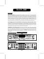
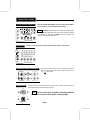
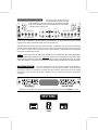
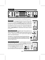
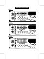
MESA BOOGIE
BASIS M 2000
OWNER'S MANUAL
The Spirit of Art in Technology
1317 Ross Street Petaluma, CA 94954
USA
Hello from the Tone Farm...
Congratulations on your choice of the BASIS M-2000 as your amplifier and welcome to
the MESA/Boogie family! As a discriminating player you probably know that you have
purchased the most comprehensive instrument for amplifying bass that is available. What you
might not realize is that this entitles you to all the experience, resources and commitment our
twenty-five years of service to musicians world wide has to offer. Our responsibility is to help
you sound great! So, if at any time you feel you need help or direction, we are here for you...a
phone call away.
BASIS M 2000
TABLE OF CONTENTS
Precautions
Overview
FRONT PANEL
Initial Set-Up
Page #
1
Description
Connect Speaker / Foot Controller / Choose Switching Logic
Output Level Control (Adjusting Listening Level)
Select Instrument Inputs
2
2
2
VACUUM TUBE CHANNEL
Set Rotary Tone Controls & Graphic E.Q.
Setting Mini-Toggles
3
Set Compressor, Threshold & Frequency
Set Listening Level
3
4
Set Bright & Normal Switch
9 Band EQ
Compressor
4
FIELD EFFECT CHANNEL
Set Rotary Controls & Graphic E.Q.
Tunable Bass Control
4&5
Set Mini Toggles
Set Compressor Threshold & Frequency
5
Set Master Control
Set Bright Normal Switch 9 Band EQ Compressor
Settings Thus Far Mix Mode Select Mix Mode Blend Control
Mixing A Distortion & Clean Sound
Graphic E.Q. Mix Assign
REAR PANEL
Description
Channel Select
Footswitch Function Assign
Balanced Output / Balanced Level
Footswitch Control
Effects Loop
Fuse
9
9
9
9 & 10
10 & 11
A.C. Receptacle
Sample Settings...Personal, Field Effect Ch. and Vacuum Tube Ch.
Parts Sheet
7
8
8
9
Speaker Out
External Select
5
6
11 & 12
12
13 - 14 - 15
16
PRECAUTIONS
Your MESA/Boogie Amplifier is a professional instrument. Please treat it with respect and operate it properly.
USE COMMON SENSE AND ALWAYS OBSERVE THESE PRECAUTIONS:
Do not expose amplifier to moisture, rain or water, direct sunlight
or extremely high temperatures.
Always insure that amplifier is properly grounded.
Always unplug AC power cord before changing fuse or any tubes.
When replacing fuse, use only same type and rating.
Avoid direct contact with heated tubes.
Insure adequate air circulation behind amplifier.
Keep amplifier away from children.
Be sure to connect to an AC power supply that meets the power
supply specifications listed on the rear of the unit.
If there is any danger of lightning occurring nearby, remove the
power plug from the wall socket in advance.
To avoid damaging your speakers and other playback equipment,
turn off the power of all related equipment before
making the connections.
Do not use excessive force in handling control buttons, switches
and controls.
Remove the power plug from the AC mains socket if the unit is to
be stored for an extended period of time.
Do not use solvents such as benzene or paint thinner to clean the
unit. Wipe off the exterior with soft cloth.
YOUR AMPLIFIER IS LOUD! EXPOSURE TO HIGH SOUND VOLUMES MAY CAUSE
PERMANENT HEARING DAMAGE!
No user serviceable parts inside. Refer service to qualified personnel. Always unplug AC power before
removing chassis.
EXPORT MODELS: Always insure that unit is wired for proper voltage. Make certain grounding
conforms with local standards.
READ AND FOLLOW INSTRUCTIONS OF PROPER USAGE.
OVERVIEW
For ease of understanding the M-2000 and to reduce the intimidation factor that one might experience upon first glance, it should
be noted that the unit may be digested one channel at a time. The only shared controls on the entire front panel are the MIX
control and the Output Level control. Thinking of the M-2000 as two completely separate pre-amplifiers - sharing one common
power section, may help you to understand it at a faster rate.
50Hz 80 180 300 600 1.2K 4K
6K
SIMUL STATE POWER
8K
50Hz 80 180 300 600 1.2K 4K
6K
8K
ACTIVE
EQ IN
EQ IN
OUT
OUT
MIX MODE
BRIGHT
MIX MODE
BRIGHT
INSTRUMENT
INPUTS
COMPRESSION
MESA BOOGIE
NORMAL
HI GAIN
PASSIVE
MIX
ASSIGN
GAIN
TREBLE
MIDDLE
BASS
MASTER
MIX
THRESHOLD
3:1
5:1
OFF
THRESHOLD
TUBE
FET
HI GAIN
CLIP
FREQUENCY
VACUUM TUBE CHANNEL
ON
BASIS M 2000
NORMAL
HI GAIN
FET
TUBE
NORMAL
COMPRESSION
50%
3:1
LOW
5:1
MASTER
OFF
FREQUENCY
OUTPUT LEVEL
TREBLE
MIDDLE
BASS
BASS FREQ.
BASS
SHIFT
POWER
FIELD EFFECT CHANNEL
VACUUM TUBE
CHANNEL CONTROLS
FIELD EFFECT
CHANNEL CONTROLS
ONLY TWO CONTROLS
THAT ARE COMMON
TO BOTH CHANNELS
NOTE You may be much too excited about playing your new toneship to spend the time now to read this manual cover to cover
explaining the M-2000's many controls and features. For those of you with the most serious tone "jones" we've included this BLine to great Bass sound. By all means...ENJOY! So that you get the most from your M-2000 for years to come, please take
the time and read this manual at some point. It contains information that you will need to know in order to optimize the M-2000's
performance so that it can, in return, catipult your playing to a new level of inspiration.
INSTANT GRATIFICATION (DEMO)
50Hz 80 180 300 600 1.2K 4K
6K
SIMUL STATE POWER
8K
50Hz 80 180 300 600 1.2K 4K
6K
8K
ACTIVE
EQ IN
EQ IN
OUT
OUT
MIX MODE
BRIGHT
MIX MODE
BRIGHT
INSTRUMENT
INPUTS
COMPRESSION
MESA BOOGIE
NORMAL
HI GAIN
TUBE
3:1
NORMAL
PASSIVE
MIX
ASSIGN
GAIN
TREBLE
MIDDLE
BASS
VACUUM TUBE CHANNEL
MASTER
OFF
FREQUENCY
BASIS M 2000
FET
MIX
THRESHOLD
5:1
COMPRESSION
50%
THRESHOLD
TUBE
FET
HI GAIN
CLIP
OUTPUT LEVEL
3:1
LOW
5:1
OFF
FREQUENCY
ON
NORMAL
HIGH
MASTER
TREBLE
MIDDLE
BASS
FIELD EFFECT CHANNEL
BASS FREQ.
BASS
SHIFT
POWER
BASIS M 2000
Description:
By now you see the M-2000 houses two completely different pre-amplifiers, one all tube, one FET. These may be footswitched
between and/or combined by utilizing the Mix Mode, in which any blend of the two may be created. The Tube Channel offers the
choice of a normal (low gain) mode operation and an all tube Hi Gain overdrive mode for wilder applications. Each of these preamps offers the full array of rotary style tone controls, producing a rich, warm blend...fast! Each Channel may then be further
customized by engaging its own nine band graphic equalizer. These channel specific EQ's may be triggered in three ways: 1. Via
the front panel's mini toggle switch 2. Via the foot controller and 3. Programmed to engage in the Mix Mode automatically. Both
EQ's, as well as the modes, can be triggered remotely by using most tip to ground switches, such as the kind found on many
Master Rack Control systems. These ports appear as 1/4 inch jacks found on the rear panel in the External Select section.
Each channel also houses a Frequency Activated (shelving type) Compressor that can be bypassed or applied in 3:1 and 5:1
ratios. The M-2000 is fitted with a parallel effects loop with a crossover enabling frequency specific effect placement as well as a
dry/wet blend control. This loop may be assigned to auto engage in any or all of the modes as well as bypassed. This crossover
can also be used to send a pre-amp signal of a selected frequency to another power amplifier for bi-amping. A Balanced Output
with pre and post EQ positions and a level control is provided for recording or live sound reinforcement applications. An output for
a Tuner is included and may be triggered remotely by the Gain switch on the Foot Controller.
The M-2000's Simul-State power section feeds two mono 1/4 inch jacks or two 3-pin XLR jacks to deliver a robust 600 Watts
RMS into 4 Ohms which is the recommended load. The toneful Simul-State circuit uses a 12AX7 driver tube to feed the power
block of 12 high quality mosfets. This design boasts the smooth warmth found in all tube circuits and the tight, immediate
response often associated with solid state amplification. As you can see, the M-2000 has all the needed features to elevate your
playing to new plateaus, yet it remains simple and straightforward to use. The following is an explanation ot the controls and a few
setting examples.
CAUTION: NEVER BLOCK AIR VENT
FRONT VIEW BASIS M-2000
50Hz 80 180 300 600 1.2K 4K
6K
SIMUL STATE POWER
8K
50Hz 80 180 300 600 1.2K 4K
6K
8K
ACTIVE
EQ IN
EQ IN
OUT
OUT
MIX MODE
BRIGHT
MIX MODE
BRIGHT
INSTRUMENT
INPUTS
COMPRESSION
MESA BOOGIE
NORMAL
HI GAIN
TUBE
3:1
NORMAL
PASSIVE
MIX
ASSIGN
TREBLE
MIDDLE
BASS
MASTER
VACUUM TUBE CHANNEL
OFF
FREQUENCY
ON
BASIS M 2000
NORMAL
HIGH
FET
MIX
THRESHOLD
5:1
GAIN
COMPRESSION
50%
THRESHOLD
TUBE
FET
HI GAIN
CLIP
OUTPUT LEVEL
3:1
LOW
5:1
OFF
MASTER
FREQUENCY
TREBLE
MIDDLE
BASS
BASS FREQ.
BASS
SHIFT
POWER
FIELD EFFECT CHANNEL
REAR VIEW BASIS M-2000
EXTERNAL SELECT
12A S.B.
SPEAKER OUT
SPEAKER
OUT
FET
TUBE
ON
OFF
FUSE
FET
MIX
MODE
EQ
SEND
SUGGESTED LOAD 4 OHMS
600 WATTS RMS
MINIMUM LOAD 2 OHMS
117 VAC 60Hz 1200VA
TUBE
HI GAIN
MIX
MODE
SPEAKER
OUT
SPEAKER OUT
PAGE 1
PRE
BALANCED OUTPUT
0%
TUBE
HI GAIN
FOOTSWITCH
FUNCTION ASSIGN
RETURN
POST
MIX MODE
TUBE
HIGH
MIX
FX LOOP AUTO
EQ
FET
EXT
FOOT
SWITCH
CROSSOVER
LOW
250 VOLTS
CHANNEL SELECT
EFFECTS LOOP
TUBE
MUTE
100%
BALANCED
LEVEL
TUNER
OUTPUT
GAIN
FOOTSWITCH
INITIAL SET-UP
CONNECT SPEAKER
First connect the M-2000 to your favorite speaker cabinet using either the 1/4 inch jacks or the 3pin XLR's. The recommended load is 4 Ohms.
SPEAKER OUT
SPEAKER
OUT
SUGGESTED LOAD 4 OHMS
600 WATTS RMS
MINIMUM LOAD 2 OHMS
SPEAKER
OUT
SPEAKER OUT
CHANNEL SELECT
EFFECTS LOOP
FET
EXT
FOOT
SWITCH
CROSSOVER
SEND
MIX MODE
TUBE
TUBE
HI GAIN
HIGH
LOW
MIX
FOOTSWITCH
CONNECT FOOT
CONTROLLER
FUNCTION ASSIGN
RETURN
0%
MUTE
100%
BALANCED
LEVEL
TUNER
OUTPUT
GAIN
FOOTSWITCH
CHOOSE SWITCHING LOGIC
FET
EXT
FOOT
SWITCH
CROSSOVER
SEND
HIGH
MIX
MIX MODE
TUBE
TUBE
HI GAIN
FOOTSWITCH
FUNCTION ASSIGN
RETURN
0%
Select FOOTSWITCH with the rotary control. (If the Foot Controller is not available, use
the rotary control to select the channels during this exercise.)
CHANNEL SELECT
EFFECTS LOOP
LOW
Then connect the M-2000 's Foot Controller to its 6-Pin Male XLR Jack.
MUTE
100%
GAIN
OUTPUT LEVEL CONTROL
(7 O'Clock)
50%
TUBE
Important... Set the Output Level Control located in the center of the front panel to 0.
FET
MIX
TUBE
FET
HI GAIN
CLIP
OUTPUT LEVEL
SELECT INSTRUMENT INPUT
ACTIVE
Connect your instrument to the appropriate Input jack (Active or Passive.) If your
instrument incorporates a pre-amp which uses a battery for power, you will probably want to
use the Active Input Jack. Most other instruments should work well with the Passive Input.
INSTRUMENT
INPUTS
PASSIVE
PAGE 2
VACUUM TUBE CHANNEL
ROTARY CONTROLS & GRAPHIC EQ
50Hz 80 180 300 600 1.2K 4K
6K
Select the VACUUM TUBE CHANNEL using the footswitch labeled TUBE on
the Foot Controller and set the controls as per this example.
8K
EQ IN
NOTE The M-2000 automatically returns to the mode that was last used upon
power-up, (when the Channel Select rotary switch is set to Footswitch.) When the
Foot Controller is not being used, the M-2000 will power-up with the mode
chosen on the Channel Select rotary switch.
OUT
MIX MODE
BRIGHT
MESA BOOGIE
NORMAL
HI GAIN
NORMAL
MIX
ASSIGN
GAIN
TREBLE
MIDDLE
BASS
MASTER
VACUUM TUBE CHANNEL
MINI TOGGLES
Locate the 3 mini toggle switches on the left side of this channel and set to these positions.
50Hz 80 180 300 600 1.2K 4K
6K
8K
EQ IN
OUT
MIX MODE
BRIGHT
MESA BOOGIE
NORMAL
HI GAIN
NORMAL
GAIN
MIX
ASSIGN
TREBLE
MIDDLE
BASS
MASTER
VACUUM TUBE CHANNEL
COMPRESSOR THRESHOLD & FREQUENCY
COMPRESSION
Set the Vacuum Tube Channel's Compressor Threshold and Frequency
Controls per this example, while leaving the Ratio toggle switch in the
OFF 3:1 (down position.)
COMPRESSION
50%
5:1
3:1
MIX
THRESHOLD
5:1
OFF
THRESHOLD
TUBE
FET
HI GAIN
CLIP
FREQUENCY
OFF
FET
TUBE
OUTPUT LEVEL
LISTENING LEVEL
50%
TUBE
5:1
OFF
FREQUENCY
With your instrument connected to the proper Input jack (Passive or Active,) SLOWLY bring up the
volume with the Output Level control while playing a note.
FET
MIX
TUBE
FET
HI GAIN
CLIP
OUTPUT LEVEL
3:1
NOTE Use care as this control is capable of unleashing substantial
power which can result in either speaker or hearing damage.
PAGE 3
BRIGHT
While playing an open string, activate the BRIGHT / NORMAL switch to the
position.)
BRIGHT / NORMAL SWITCH
50Hz 80 180 300 600 1.2K 4K
ACTIVE
6K
(up
NORMAL
8K
Become familiar with the frequencies that this
switch enhances as it works along side the
Graphic Equalizers' top 3 bands ( 4 - 6 - & 8K ) to
bring out the upper harmonics and sparkle.
EQ IN
OUT
MIX MODE
BRIGHT
INSTRUMENT
INPUTS
NORMAL
9 BAND EQ
Set the Tube Channel's 9 Band Equalizer per this example (if you have not done so) and activate it by using
EQ IN
the 3 position mini toggle switch
(up position.)
50Hz 80 180 300 600 1.2K 4K
6K
OUT
MIX MODE
ACTIVE
EQ IN
To activate the 9 Band Equalizer via the
Footcontroller, you must have the front panel 3
position mini toggle switch in the OUT position or in
the MIX MODE position. There are two of these
switches, one per channel located to the right and
left respectfully. When the E.Q. 3 position switch is
in the MIX MODE, the E.Q. will automatically be
engaged.
OUT
MIX MODE
BRIGHT
INSTRUMENT
INPUTS
NORMAL
Turn on the Compressor by selecting the 3:1 position on the face panel of the M-2000. With the
Threshold set per the example to the left, play a low note and sweep the Frequency control clockwise.
You will notice less compression as you pass 12 O' clock until there is none at all. Now reverse this
procedure. Play a high note (you may have to change the Threshold to maximize the effect for this
test) and sweep the Frequency control counter-clockwise. As you pass 12 O' clock you will again hear
the compression effect lessen. This "Shelving" (frequency specific) control allows the compression of
the low frequencies without affecting the high frequencies and similarly the opposite. To compress
the lows and highs equally, set the Frequency control straight up to 12 O' clock and adjust the
Threshold control accordingly. Select the 5:1 ratio position for a much "thicker" compression.
Remember that the Threshold setting is crucial to obtaining a usable, musical compression
setting. Following the same procedure, we will run through the Field Effect Channel.
COMPRESSOR
COMPRESSION
THRESHOLD
3:1
8K
5:1
OFF
FREQUENCY
FIELD EFFECT CHANNEL
ROTARY CONTROLS & GRAPHIC EQ
50Hz 80 180 300 600 1.2K 4K
6K
8K
EQ IN
OUT
MIX MODE
BRIGHT
BASIS M 2000
ON
NORMAL
HIGH
Set the FIELD EFFECT CHANNEL rotary controls and the 9 Band Graphic E.Q.
per this example, making sure that the FET channel's MASTER control
is set to zero. You will notice there is no Gain control in this channel.
This was done to make room for a different tone control wiring scheme.
The FET channel's Treble and Mid are wired in the same fashion as that of
the Tube channel (though they may seem to enhance different frequencies
because of the very nature of the FET design.) The Bass controls are
where the similarity ends.
LOW
MASTER
TREBLE
MIDDLE
BASS
BASS FREQ.
FIELD EFFECT CHANNEL
BASS
SHIFT
POWER
PAGE 4
TUNABLE BASS CONTROL
NOTE When switch HIGH
is in the "Down" position
the controls, BASS and
BASS FREQ., shape LOW
and control frequencies from
30Hz to 100Hz.
1.2K
In this channel the bass frequencies are shaped utilizing a pair of parametric type controls.
Two rotary controls, Bass and Bass Frequency enable you to
center in on the region of lows that you wish to enhance and
4K 6K 8K
boost or cut them to your desire. Just to the right of these two
EQ IN
controls there is a mini-toggle switch that enables you to
OUT
"Shift" the region of bass that the Bass Frequency rotary
MIX MODE
BRIGHT
control affects.
ON
2000
NORMAL
HIGH
As you might have guessed, this mini-toggle switch lowers
the action of the control when in the down position and
LOW
shifts the region up higher when the toggle is in the up
POWER
BASS BASS FREQ.
BASS
SHIFT
position. So that you have complete control of the entire
NNEL
range of low frequencies, the Low and High ranges of the
Bass Shift overlap at 100Hz.. This overlap occurs at 5:30
(fully cranked) on the Bass Frequency control when the Bass Shift switch is in the Low position. When the Shift is switched to High
you will find this 100Hz. overlap at 7:30 (all the way down) on the Bass Frequency control. This difference in Bass controls in the
FET channel is crucial to its tighter attack and cut-off point characteristics, which is an integral part of the FET channel's
personality...making it strikingly different in nature to the Vacuum Tube channel.
NOTE When switch HIGH
is in the "Up" position the
controls, BASS and
BASS FREQ., shape LOW
and control frequencies from
100Hz to 200Hz.
MINI TOGGLES
Locate the 3 mini toggle switches on the right side of this channel and set to these positions.
50Hz 80 180 300 600 1.2K 4K
6K
8K
EQ IN
OUT
MIX MODE
BASIS M 2000
BRIGHT
ON
NORMAL
HIGH
MASTER
TREBLE
MIDDLE
BASS
BASS FREQ.
LOW
FIELD EFFECT CHANNEL
POWER
Set the Field Effect Channel Compressor's Threshold and Frequency
Controls per this example, while leaving the Ratio toggle
COMPRESSION
switch in the OFF 3:1
(down position.)
COMPRESSOR THRESHOLD & FREQUENCY
50%
COMPRESSION
5:1
OFF
TUBE
3:1
FET
MIX
THRESHOLD
THRESHOLD
TUBE
FET
HI GAIN
CLIP
3:1
5:1
5:1
OFF
OUTPUT LEVEL
FREQUENCY
MASTER CONTROL
OFF
FREQUENCY
With your instrument still connected to the appropriate jack, SLOWLY bring up the FET channel's
MASTER Control to the desired volume.
BASIS M 2000
NORMAL
HIGH
LOW
MASTER
TREBLE
MIDDLE
BASS
BASS FREQ.
FIELD EFFECT CHANNEL
BASS
SHIFT
PAGE 5
BRIGHT
Again, play an open string and activate the Bright / Normal switch by selecting the (up
( up position. )
position.)
BRIGHT / NORMAL SWITCH
NORMAL
50Hz 80 180 300 600 1.2K 4K
6K
8K
EQ IN
OUT
MIX MODE
BRIGHT
MESA BOOGIE
ON
NORMAL
HIGH
LOW
MASTER
TREBLE
MIDDLE
BASS
BASS FREQ.
POWER
BASS
SHIFT
FIELD EFFECT CHANNEL
EQ IN
Engage the 9-Band Graphic Equalizer
9 BAND EQ
50Hz 80 180 300 600 1.2K 4K
6K
8K
OUT
(toggle in the up position) and notice that though they are
the same controls, they react differently because of the FET
channel's personality.
MIX MODE
EQ IN
OUT
MIX MODE
BRIGHT
BASIS M 2000
ON
NORMAL
To activate the 9 Band Equalizer via the Footcontroller, you
must have the front panel 3 position mini toggle switch in the OUT
position or in the MIX MODE position. There are two of these
switches, one per channel located to the right and left respectfully.
HIGH
LOW
MASTER
TREBLE
MIDDLE
BASS
BASS FREQ.
FIELD EFFECT CHANNEL
COMPRESSOR
COMPRESSION
3:1
THRESHOLD
5:1
OFF
FREQUENCY
BASS
SHIFT
POWER
When one of the E.Q. 3 position switches is in the MIX MODE, that
E.Q. will automatically be engaged when the MIX MODE is
selected.
Turn on the Compressor by selecting the 3:1 position on the Face Panel of the M-2000. With the
Threshold set per the example to the left, play a low note and sweep the Frequency control clockwise.
You will notice less compression as you pass 12 O' clock until there is none at all. Now reverse this
procedure. Play a high note (you may have to change the Threshold to maximize the effect for this
test) and sweep the Frequency control counter-clockwise. As you pass 12 O' clock you will again
hear the compression effect lessen. This "Shelving" (frequency specific) allows the compression of
the low frequencies without affecting the high frequencies and similarly the opposite.
To compress the lows and highs equally, set the Frequency control straight up to 12 O' clock and
adjust the Threshold control accordingly. Select the 5:1 ratio position for a much "thicker"
compression, remembering that the Threshold setting is crucial to obtaining a useful, musical
compression setting.
PAGE 6
VACUUM TUBE CHANNEL SETTINGS THUS FAR
50Hz 80 180 300 600 1.2K 4K
6K
SIMUL STATE POWER
8K
ACTIVE
EQ IN
OUT
MIX MODE
BRIGHT
INSTRUMENT
INPUTS
NORMAL
HI GAIN
TUBE
3:1
NORMAL
PASSIVE
MIX
ASSIGN
50%
COMPRESSION
MESA BOOGIE
5:1
GAIN
TREBLE
MIDDLE
BASS
MASTER
OFF
FREQUENCY
VACUUM TUBE CHANNEL
FET
MIX
THRESHOLD
TUBE
FET
HI GAIN
CLIP
OUTPUT LEVEL
FIELD EFFECT CHANNEL SETTINGS THUS FAR
SIMUL STATE POWER
50Hz 80 180 300 600 1.2K 4K
6K
8K
EQ IN
OUT
MIX MODE
BRIGHT
COMPRESSION
50%
TUBE
BASIS M 2000
FET
MIX
THRESHOLD
TUBE
FET
HI GAIN
CLIP
OUTPUT LEVEL
ON
NORMAL
HIGH
3:1
LOW
5:1
OFF
FREQUENCY
MASTER
TREBLE
MIDDLE
BASS
BASS FREQ.
BASS
SHIFT
POWER
FIELD EFFECT CHANNEL
MIX MODE
MIX MODE SELECT
CHANNEL SELECT
FET
EXT
FOOT
SWITCH
Engage the MIX Mode by triggering the MIX switch on the M-2000 Foot Control panel. (If the foot
controller is not available, use the rotary switch on the right side of the Rear Panel and select the MIX
position.)
MIX MODE
TUBE
TUBE
HI GAIN
MIX MODE BLEND CONTROL
COMPRESSION
50%
TUBE
FET
MIX
THRESHOLD
THRESHOLD
FET
TUBE
HI GAIN
FREQUENCY
While playing a note on an open string, sweep the MIX Control from the center (Equal
Blend of Tube and FET), to the left (100% Tube) and to the right (100% FET.) Between
COMPRESSIONthese three positions lie a myriad of unique and outrageous sounds that you will find yourself
exploring for many years. The ability to combine two completely separate front end technologies
allows you to "custom-build" the pre-amp of your dreams, by simply using the MIX Pan Pot.
OUTPUT LEVEL
CLIP
FREQUENCY
3:1
The5:1
MIX Mode also makes possible a third footswitchable sound from a two channel layout that
isOFFdistinctly different from either channel. Now that you have heard one possible way of using
the MIX Mode, we encourage you to experiment and create some sounds of your own!
PAGE 7
Next, let's try mixing a distortion (or maybe just
a slightly overdriven) sound from the VACUUM
TUBE CHANNEL with a tight clean sound from the FIELD EFFECT CHANNEL.
While still in the MIX Mode, select the HI-GAIN setting of the MIX ASSIGN Switch
in the TUBE Channel's lower left corner.
MIXING A DISTORTION and a CLEAN SOUND
50Hz 80
180
EQ IN
OUT
MIX MODE
BRIGHT
COMPRESSION
50%
3:1
GAIN
TREBLE
MIDDLE
BASS
EQ IN
OUT
MIX MODE
BRIGHT
MASTER
MIX
THRESHOLD
OFF
VACUUM TUBE CHANNEL
FREQUENCY
NORMAL
HI GH
FET
THRESHOLD 3:1
TUBE
FET
HI GAIN
CLIP
OUTPUT LEVEL
LOW
5:1
5:1
MIX
8K
BASIS M 2000
TUBE
HI GAIN
ASSIGN
NORMAL
6K
COMPRESSION
MESA BOOGIE
NORMAL
4K
OFF
FREQUENCY
MASTER
TREBLE
MIDDLE
BASS
SHIFT
BASS BASS FREQ.
FIELD EFFECT CHANNEL
Set the controls in both channels to the setting shown in the above illustration. For this example, we have chosen a medium
overdrive sound to audition. Select the MIX Mode (if you have not already done so.)
Start with the MIX Control panned hard right (100% FET) and sweep left. At slightly before 12:00, you will hear the overdrive from
the TUBE Channel's HI-GAIN Mode start to come into the mix. Continue sweeping toward the TUBE Channel until the desired
blend is reached. To adjust the amount of overdrive in the TUBE Channel, simply raise or lower the GAIN Control until you find the
intensity (amount of distortion) that you desire.
NOTE It may be helpful to reduce the setting of the rotary BASS Control in the TUBE Channel when using the HI-GAIN Mode,
especially with higher settings of the GAIN Control. High settings of these two controls simultaneously will often produce a flubby,
indistinct attack. If you need more low frequencies when dialing up Hi Gain sounds, try using the lower bands ( 50 - 80 - & 180K )
of the Graphic Equalizer as it occurs later in the signal path and is therefore less likely to be detrimental to the attack characteristic.
GRAPHIC E.Q. MIX ASSIGN
One or both 9 Band Equalizers may be automatically engaged when the MIX Mode is
called up via the footswitch (or via the Rear Panel rotary switch.) Simply select the MIX
ASSIGN (down position) of the 3 position E.Q. mini-toggle switch that is adjacent to each Equalizer and it will be activated
automatically every time you choose the MIX Mode. Needless to say, this increases the sonic power of the MIX Mode
exponentially.
50Hz 80 180 300 600 1.2K 4K
6K
8K
SIMUL STATE POWER
50Hz 80 180 300 600 1.2K 4K
6K
8K
EQ IN
EQ IN
OUT
OUT
MIX MODE
MIX MODE
MESA BOOGIE
BASIS M 2000
Now that we've run through the two channels, we are ready to spin the unit around and review the M-2000s' Rear Panel.
REST AREA
PAGE 8
REAR PANEL
EXTERNAL SELECT
12A S.B.
SPEAKER OUT
SPEAKER
OUT
FET
TUBE
ON
OFF
FUSE
FET
MIX
MODE
117 VAC 60Hz 1200VA
EQ
SEND
SUGGESTED LOAD 4 OHMS
600 WATTS RMS
MINIMUM LOAD 2 OHMS
TUBE
HI GAIN
MIX
MODE
MIX MODE
TUBE
TUBE
HI GAIN
HIGH
MIX
FX LOOP AUTO
EQ
FET
EXT
FOOT
SWITCH
CROSSOVER
LOW
250 VOLTS
CHANNEL SELECT
EFFECTS LOOP
TUBE
FOOTSWITCH
FUNCTION ASSIGN
RETURN
POST
SPEAKER
OUT
SPEAKER OUT
PRE
BALANCED OUTPUT
0%
BALANCED
LEVEL
GAIN
MUTE
100%
TUNER
OUTPUT
FOOTSWITCH
Let's start from the right, as you are looking at the Rear Panel and go through the features one at a time. We are starting from the
right because the more frequently used features begin here, as you have probably already experienced.
CHANNEL SELECT
This rotary control engages the two channels and their Modes of operation.
When the M-2000 Foot Controller is not available, use this rotary control to
choose the desired mode of operation. To use the M-2000 Foot Controller, set the CHANNEL SELECT
Rotary Switch to the "Footswitch" position. The M-2000 may also be controlled via an external switching
source that uses 1/4 inch "tip to ground" ports. This way, the M-2000 can easily be interfaced to existing
MIDI controlled systems, allowing instant access to the Modes under MIDI program change commands.
Set the CHANNEL SELECT to "EXT" and connect the six 1/4 inch jacks found in the EXTERNAL SELECT
section (far left of the Rear Panel) to the switching source. Unshielded cable is preferable for this
application. Trigger the M-2000 Modes by programming your switching system to "ground" the
corresponding M-2000 External Select jack to bring up the Mode of your choice under a given MIDI
program number.
FOOTSWITCH FUNCTION ASSIGN
This mini-toggle switch programs the GAIN switch on the
M-2000 Foot Controller. The GAIN switch serves a dual
M2000
purpose in the switching scheme of the M-2000. It may be used in its normal mode to select the TUBE
Channel's HI-GAIN Mode. In this case, set the FOOTSWITCH FUNCTION ASSIGN Switch to the GAIN
(right) position. This toggle switch may also be used in conjunction with the TUNER Output to
produce a "silent tuning" mode for stage use.
CHANNEL SELECT
FET
EXT
FOOT
SWITCH
TUNER
OUTPUT
BALANCED OUTPUT / BALANCED LEVEL
This electronically balanced XLR jack provides two
possible ways of interfacing to mixing consoles for live
and recording situations. POST: captures all the robust warmth of the M-2000's two powerful and distinct
pre-amp circuits, as well as giving you the added flexibility of 18 bands (9 per channel) of "Bass friendly"
MIX
graphic equalization. Add to this the frequency specific compression
FX LOOP AUTO
circuits in each channel that are tweaked for Bass - and we think
RETURN
PRE
POST
0%
100%
you too will find the M-2000 is the ultimate way to capture Bass
direct. Switched to PRE: all M-2000 circuitry is removed from the
signal path and the signal is then fed straight from either Instrument
Input jack to the Balanced Level control and straight on to the
BALANCED OUTPUT
PAGE 9
BALANCED
LEVEL
TUNER
OUTPUT
TUBE
HI GAIN
FOOTSWITCH
FUNCTION ASSIGN
GAIN
MUTE
FOOTSWITCH
FOOTSWITCH
FUNCTION ASSIGN
GAIN
MUTE
FOOTSWITCH
FUNCTION ASSIGN
GAIN
MUTE
Connect a tuner to the 1/4 inch jack labeled TUNER OUTPUT (located just to the left of the 6 pin
XLR Footswitch jack.) Select "MUTE" with the FOOTSWITCH FUNCTION ASSIGN (toggle
switch to the left.) When the GAIN switch is selected on the M-2000 Foot Controller, all
sound to the power section will be muted and the instrument signal will pass straight
through to the TUNER OUTPUT jack.
MIX MODE
TUBE
FOOTSWITCH
CHANNEL SELECT
FET
EXT
FOOT
SWITCH
MIX MODE
TUBE
TUBE
HI GAIN
FOOTSWITCH
FUNCTION ASSIGN
MUTE
GAIN
FOOTSWITCH
BALANCED OUTPUT / BALANCED LEVEL (Continued)
Balanced Output XLR jack. Basically,
this means that your instrument is
going directly into the console with no alteration from the M-2000. Sometimes this is preferred when
playing venues with large sound systems that have plenty of low frequency
power of their own and don't always need the added shaping that is happening
on the stage.
RETURN
0%
The BALANCED LEVEL control enables you to match the optimum levels
required by most mixing consoles. It is always good practice to "zero out" the
level on the M-2000 before connecting it to a console, just in case the channel
at the console was last used for a weak signal and is set to extremes.
FET
EXT
FOOT
SWITCH
TUNER
OUTPUT
MIX MODE
TUBE
TUBE
HI GAIN
FOOTSWITCH
FUNCTION ASSIGN
MUTE
100%
BALANCED
LEVEL
CHANNEL SELECT
GAIN
FOOTSWITCH
NOTE It is NOT necessary to connect a speaker load to the M-2000 when using the BALANCED OUTPUT for recording or
live use. No damage to the amplifier will occur from having no load connected. Simply turn the OUTPUT LEVEL (located in the
center, bottom portion of the Front Panel) to 7:00 (this would be the Off position for this control.)
NOTE In certain situations a hum or buzz may occur when using the direct BALANCED OUTPUT. This occurs due to different
references (impedance) to ground between the M-2000 and the console. If this occurs you may want to lift the M-2000 ground
path by either using an XLR Ground Lift Adapter or by simply making a cable with the grounds disconnected. You might also try a
simple A.C. Ground Lift ( 3 to 2 adapter ) on the M-2000's power cord just to make sure the noise that you are experiencing is
not A.C. Ground related.
This 6 pin XLR jack accepts and powers the M-2000 FOOT
CONTROL unit. It uses a locking type jack so that the foot controller
will not be accidentally removed during a performance. Depress the catch on the plug when removing the
foot controller's cable from the amplifier.
FOOTSWITCH CONTROL
CHANNEL SELECT
FET
EXT
FOOT
SWITCH
MIX MODE
TUBE
TUBE
HI GAIN
FOOTSWITCH
FUNCTION ASSIGN
RETURN
0%
MUTE
100%
BALANCED
LEVEL
The M-2000 has an advanced way of
EFFECTS LOOP
dealing with signal processing. You may
TUBE
CROSSOVER
ON
FET
choose not only how much of a given effect you wish to blend
MIX
SEND
OFF
MODE
with the dry signal, but also which frequencies will receive
HIGH
LOW
MIX
FX LOOP AUTO
processing! The loop is wired in parallel with the direct
signal, ensuring that your tone stays bold and authoritative.
RETURN
0%
100%
It is comprised of a SEND and a RETURN that appear as a pair of 1/4 inch jacks
forming a bridge between the pre-amp and power sections of the M-2000.
These are then fed to the crossover circuit, allowing you control of the
frequencies that you wish to apply signal processing to, via the CROSSOVER
BALANCED
rotary control. To either side (and slightly below this rotary control,) you will see
LEVEL
LOW and HIGH. When this control is swept to the left toward the LOW
position, the low frequencies will be the primary ones that receive
processing.
TUNER
OUTPUT
EFFECTS LOOP
PAGE 10
GAIN
FOOTSWITCH
CHANNEL SELECT
FET
EXT
FOOT
SWITCH
MIX MODE
TUBE
TUBE
HI GAIN
FOOTSWITCH
FUNCTION ASSIGN
MUTE
TUNER
OUTPUT
GAIN
FOOTSWITCH
When panned hard left
CHANNEL SELECT
EFFECTS LOOP
(7:00), mostly lows will
TUBE
FET
MIX MODE
CROSSOVER
ON
FET
EXT
TUBE
SEND
pass this junction. When the rotary control is swept toward
MIX
FOOT
OFF
TUBE
MODE
SWITCH
HI
GAIN
HIGH, the crossover will allow more of the upper harmonic
HIGH
LOW
MIX
range to receive processing. Panned hard right (5:00), mostly
FX LOOP AUTO
FOOTSWITCH
FUNCTION ASSIGN
highs will be present in the loop's signal path. With the
RETURN
GAIN
MUTE
100%
0%
CROSSOVER control set straight up (12:00), the whole range of frequencies
(lows and highs) pass equally through the EFFECTS LOOP. The MIX Control
lets you decide how much of the frequency specific affected signal you
wish to blend with the dry (unaffected) signal. Panned hard left, (0%)
BALANCED
TUNER
removes all the wet signal from the mix. Panned hard right (100%) allows only
LEVEL
OUTPUT
FOOTSWITCH
the wet signal to pass the MIX Control. In general, its always a good idea to set
up your signal processor with its mix control at 100% wet and then slowly raise
the M-2000 's FX LOOP MIX Control until you reach the desired blend. This scheme preserves the integrity of the attack and
punch characteristics the M-2000 is capable of delivering (when no processing is being used.) Finally, the FX LOOP AUTO
ASSIGN rotary control activates the loop as well as allowing you to engage it automatically in any of the three Modes when they
are called up with either the CHANNEL SELECT Rotary Control or the FOOT CONTROLLER.
EFFECTS LOOP (Continued)
NOTE A great way to check out the power of this advanced loop is to try this simple exercise: 1. Connect your favorite signal
processor to the SEND and RETURN (Input to SEND - Output to RETURN.) May we humbly suggest a "chorus" program as these
seem to be great for the purpose of this exercise. 2. Set the signal processor's Dry / Wet Blend to 100% Wet. 3. Sweep the
CROSSOVER control to approximately 3:00 (this will allow mostly high frequencies to be processed.) 4. Use the FX LOOP AUTO
assign rotary to activate the loop in the Mode that you wish to play in. 5. While playing an open string, slowly increase the FX
LOOP MIX control until you reach the desired dry / wet blend.
Right away you should be able to appreciate the fact, that, while you have chorus (or whatever effect you choose) on "top" of your
sound, you have not lost the punch and authority that is so often sacrificed when using effects...especially less expensive units that
don't incorporate high quality operational amplifiers in their mixer and output stages. At this time you may also want to sweep the
CROSSOVER control over to 9:00 to experience the same test passing mostly low frequencies through the loop. While quite
different and interesting, we think most players will want to process their highs, keeping the bottom end tight with unprocessed
definition.
SPEAKER OUT
The BASIS M-2000 provides two types of
interconnects for powering speaker enclosures,
XLR and the standard 1/4 inch phono jacks. Each of these formats include a
pair of jacks that are wired in parallel and which may be used individually or
together to power additional cabinets. The recommended speaker load
impedance for the M-2000 is 4 Ohms at which the mighty SIMULSTATE power section is capable of delivering a whopping 625 watts RMS
before clip, and peaks of over 2000 watts! A speaker load of 8 Ohms may
also be used and at this impedance, though the overall power will be
reduced to roughly 300 watts.
PAGE 11
SPEAKER OUT
SPEAKER
OUT
SUGGESTED LOAD 4 OHMS
600 WATTS RMS
MINIMUM LOAD 2 OHMS
SPEAKER OUT
SPEAKER
OUT
CAUTION: NEVER BLOCK AIR VENTS
This section of the Rear Panel as we mentioned earlier,
while explaining the CHANNEL ASSIGN section, is
provided to make possible the triggering of the M-2000 Modes from remote switching
sources. The six 1/4 inch jacks represent all four Modes of operation and the two
channels' Graphic Equalizers. These functions may be controlled by connecting most
any "tip to ground" type switcher to the appropriate jacks and grounding them. This
method of Mode selection is provided so that the M-2000 may be easily interfaced to a
system using MIDI Program Change Commands as a switching format.
EXTERNAL SELECT
EXTERNAL SELECT
9A S.B.
FET
TUBE
FUSE
250 VOLTS
EQ
EQ
TUBE
HI GAIN
117 VAC 60Hz 1200VA
MIX
MODE
NOTE
If you wish to use the External Select Jacks to call up a Mode or E.Q., you must have the Rotary Mode Select Switch
(located on the right side of the Rear Panel) set to the EXT position. These External Select Jacks can always be used to select a
Mode, regardless of the state of any other switching logic.
This is the A.C. Mains Fuse for the M-2000. REPLACE ONLY WITH A
SLO-BLO TYPE FUSE OF THE SAME RATING. THIS IS EXTREMELY
IMPORTANT, AS THE M-2000 DRAWS A SUBSTANTIAL AMOUNT OF CURRENT AT
HIGH OUTPUT LEVEL SETTINGS.
FUSE
EXTERNAL SELECT
FET
TUBE
9A S.B.
FUSE
EQ
EQ
250 VOLTS
FUSE RATING ( USA ) 10 A S.B. / 250 VOLTS ONLY
= 117
FUSE RATING ( IEXPORT ) 6 1/4 A S.B. / 250 VOLTS ONLY
= All Others
100 / 220 / 230 / 240
The "Euro Style" A.C. cord connector that is supplied with the
M-2000 makes set-ups and tear-downs after the gig a snap.
It also makes de-racking much easier when you wish to remove the unit from a hard
wired rack system where all the A.C. cords have been cut to length. Additional heavy
duty cords are available should you ever need one...simply call us direct and we can ship
one directly to you for a nominal charge, plus shipping costs. Make sure the A.C. Cord is
firmly in its socket (receptacle) before powering up the unit.
A.C. RECEPTACLE
CAUTION: NEVER BLOCK AIR VENTS
MIX
MODE
EXTERNAL SELECT
9A S.B.
FET
TUBE
FUSE
250 VOLTS
117 VAC 60Hz 1200VA
SPEAKER OUT
TUBE
HI GAIN
117 VAC 60Hz 1200VA
EQ
EQ
TUBE
HI GAIN
MIX
MODE
SPEAKER
OUT
CAUTION: NEVER BLOCK AIR VENTS
SUGGESTED LOAD 4 OHMS
600 WATTS RMS
MINIMUM LOAD 2 OHMS
SPEAKER
OUT
SPEAKER OUT
CAUTION: NEVER BLOCK AIR VENTS
EPILOGUE
We hope this manual has answered most of your operating questions and that you now feel confident to start
experimenting on your own. The M-2000 was created in the pioneer spirit and from its conception, was
intended to be an instrument of limitless expression. As you become more familiar with the unit, we're sure that you will realize that
the M-2000 is a wise investment in your future as a bassist and one of the best things you ever did for your musical pursuits. We
are proud to be your amplifier company. Thank you for trusting us with your sound...Best Wishes !
PAGE 12
Settings Templates for Your Personal Favorite M-2000 Sounds
50Hz 80 180 300 600 1.2K 4K
6K
SIMUL STATE POWER
8K
50Hz 80 180 300 600 1.2K 4K
6K
8K
ACTIVE
EQ IN
EQ IN
OUT
OUT
MIX MODE
BRIGHT
MIX MODE
BRIGHT
INSTRUMENT
INPUTS
COMPRESSION
MESA BOOGIE
NORMAL
HI GAIN
TUBE
PASSIVE
5:1
MIX
ASSIGN
GAIN
TREBLE
MIDDLE
BASS
MASTER
OFF
50Hz 80 180 300 600 1.2K 4K
6K
MIX
THRESHOLD
TUBE
FET
HI GAIN
CLIP
FREQUENCY
VACUUM TUBE CHANNEL
NORMAL
HIGH
3:1
LOW
5:1
MASTER
OFF
FREQUENCY
OUTPUT LEVEL
TREBLE
MIDDLE
BASS
BASS FREQ.
BASS
SHIFT
POWER
FIELD EFFECT CHANNEL
SIMUL STATE POWER
8K
ON
BASIS M 2000
FET
THRESHOLD
3:1
NORMAL
COMPRESSION
50%
50Hz 80 180 300 600 1.2K 4K
6K
8K
ACTIVE
EQ IN
EQ IN
OUT
OUT
MIX MODE
BRIGHT
MIX MODE
BRIGHT
INSTRUMENT
INPUTS
COMPRESSION
MESA BOOGIE
NORMAL
HI GAIN
TUBE
PASSIVE
5:1
MIX
ASSIGN
GAIN
TREBLE
MIDDLE
BASS
MASTER
OFF
50Hz 80 180 300 600 1.2K 4K
6K
THRESHOLD
TUBE
FET
HI GAIN
CLIP
FREQUENCY
VACUUM TUBE CHANNEL
NORMAL
HIGH
3:1
LOW
5:1
MASTER
OFF
FREQUENCY
OUTPUT LEVEL
TREBLE
MIDDLE
BASS
BASS FREQ.
BASS
SHIFT
POWER
FIELD EFFECT CHANNEL
SIMUL STATE POWER
8K
ON
BASIS M 2000
FET
MIX
THRESHOLD
3:1
NORMAL
COMPRESSION
50%
50Hz 80 180 300 600 1.2K 4K
6K
8K
ACTIVE
EQ IN
EQ IN
OUT
OUT
MIX MODE
BRIGHT
MIX MODE
BRIGHT
INSTRUMENT
INPUTS
COMPRESSION
MESA BOOGIE
NORMAL
HI GAIN
TUBE
3:1
NORMAL
PASSIVE
MIX
ASSIGN
TREBLE
MIDDLE
BASS
VACUUM TUBE CHANNEL
MASTER
OFF
FREQUENCY
BASIS M 2000
FET
MIX
THRESHOLD
5:1
GAIN
COMPRESSION
50%
THRESHOLD
TUBE
FET
HI GAIN
CLIP
OUTPUT LEVEL
PAGE 13
3:1
LOW
5:1
OFF
FREQUENCY
ON
NORMAL
HIGH
MASTER
TREBLE
MIDDLE
BASS
FIELD EFFECT CHANNEL
BASS FREQ.
BASS
SHIFT
POWER
Sample Settings - Field Effect Channel
Punch Funk
SIMUL STATE POWER
50Hz 80 180 300 600 1.2K 4K
6K
8K
EQ IN
OUT
MIX MODE
BRIGHT
COMPRESSION
50%
ON
BASIS M 2000
NORMAL
HIGH
FET
MIX
THRESHOLD 3:1
FET
5:1
CLIP
MASTER
OFF
MIDDLE
BASS
BASS FREQ.
FIELD EFFECT CHANNEL
FREQUENCY
OUTPUT LEVEL
TREBLE
LOW
BASS
SHIFT
POWER
Scooped FET
SIMUL STATE POWER
50Hz 80 180 300 600 1.2K 4K
6K
8K
EQ IN
OUT
MIX MODE
BRIGHT
COMPRESSION
50%
ON
BASIS M 2000
NORMAL
HIGH
FET
THRESHOLD 3:1
MIX
FET
5:1
CLIP
MASTER
OFF
MIDDLE
BASS
BASS FREQ.
LOW
BASS
SHIFT
POWER
FIELD EFFECT CHANNEL
FREQUENCY
OUTPUT LEVEL
TREBLE
Articulate Solo
SIMUL STATE POWER
50Hz 80 180 300 600 1.2K 4K
6K
8K
EQ IN
OUT
MIX MODE
BRIGHT
COMPRESSION
50%
BASIS M 2000
FET
MIX
NORMAL
HIGH
THRESHOLD 3:1
FET
5:1
CLIP
OUTPUT LEVEL
ON
OFF
FREQUENCY
MASTER
TREBLE
MIDDLE
BASS
FIELD EFFECT CHANNEL
PAGE 14
BASS FREQ.
LOW
BASS
SHIFT
POWER
Sample Settings - Vacuum Tube Channel
Fat R & B
50Hz 80 180 300 600 1.2K 4K
ACTIVE
6K
SIMUL STATE POWER
8K
EQ IN
OUT
MIX MODE
BRIGHT
INSTRUMENT
INPUTS
MESA
NORMAL
HI GAIN
TUBE
THRESHOLD
3:1
NORMAL
PASSIVE
50%
COMPRESSION
BOOGIE
TUBE
5:1
GAIN
MIX
ASSIGN
TREBLE
MIDDLE
BASS
MASTER
MIX
OFF
HI GAIN
FREQUENCY
VACUUM TUBE CHANNEL
OUTPUT LEVEL
Thumb Funk
50Hz 80 180 300 600 1.2K 4K
ACTIVE
6K
SIMUL STATE POWER
8K
EQ IN
OUT
MIX MODE
BRIGHT
INSTRUMENT
INPUTS
MESA BOOGIE
NORMAL
HI GAIN
TUBE
3:1
NORMAL
PASSIVE
50%
COMPRESSION
THRESHOLD
5:1
MIX
ASSIGN
ASSIGN
GAIN
TREBLE
MIDDLE
BASS
MASTER
MIX
TUBE
OFF
HI GAIN
FREQUENCY
VACUUM TUBE CHANNEL
OUTPUT LEVEL
Driving Rock
50Hz 80 180 300 600 1.2K 4K
ACTIVE
6K
SIMUL STATE POWER
8K
EQ IN
OUT
MIX MODE
BRIGHT
INSTRUMENT
INPUTS
INPUTS
MESA BOOGIE
NORMAL
HI GAIN
TUBE
3:1
PASSIVE
NORMAL
MIX
ASSIGN
50%
COMPRESSION
THRESHOLD
5:1
GAIN
TREBLE
MIDDLE
BASS
VACUUM TUBE CHANNEL
PAGE 15
MASTER
MIX
TUBE
OFF
HI GAIN
FREQUENCY
OUTPUT LEVEL
EQ IN
MIX
ASSIGN
NORMAL
NORMAL
HI GAIN
MIX MODE
BRIGHT
OUT
8K
POT #
592737
POT #
BASS
592148
POT #
MASTER
592151
POT #
FET
MIX
MODE
SUGGESTED LOAD 4 OHMS
600 WATTS RMS
MINIMUM LOAD 2 OHMS
SPEAKER OUT
XLR JACK
pt# 614028
POT #
592379
FREQUENCY
592379
3:1 THRESHOLD
POT #
OFF
SWITCH
pt# 607203
5:1
COMPRESSION
EQ pt# 588540
KNOB pt# 408530
6K
POT #
592148
MIDDLE
LED
pt# 395620
592148
TREBLE
ALL JACKS
(6) pt# 618100
EQ
EXTERNAL SELECT
TUBE
TUBE
HI GAIN
SPEAKER OUT
KNOB pt# 408004
(all 5 knobs)
VACUUM TUBE CHANNEL
GAIN
MESA BOOGIE
50Hz 80 180 300 600 1.2K 4K
SWITCH pt# 607203
FRONT VIEW BASIS M-2000
JACK pt# 618102
ACTIVE
INSTRUMENT
INPUTS
PASSIVE
JACK pt# 618102
SWITCH pt# 607101
SWITCH pt# 607101
EQ
REAR VIEW BASIS-M2000
FUSE HOLDER
pt# 7903243
FUSE pt# 790122
12A S.B.
FUSE
250 VOLTS
117 VAC 60Hz 1200VA
A.C. RECEPTACLE
pt# 613713
SIMUL STATE POWER
50%
POT #
592151
MIX
POT #
2736
OUTPUT
LEVEL
OFF
3:1
5:1
KNOB pt# 408530
POT #
2379
POT #
2151
POT #
8K
592737
TUBE
CROSSOVER
POT pt#
2379
MIX
100%
SEND
POT pt# RETURN
2737
HIGH
EFFECTS LOOP
FET
MIX
MODE
LOW
0%
POT pt#
2148
BALANCED
LEVEL
EQ IN
ON
POWER
PILOT LIGHT
pt# 703047
LENS pt#
703786
PILOT LIGHT
HOLDER
pt# 703900
SWITCH
pt# 602110
607101
KNOB pt# 408004
MIX MODE
TUBE
TUBE
HI GAIN
GAIN
SWITCH
pt# 607101
XLR JACK
pt# 620414
FOOTSWITCH
MUTE
FOOTSWITCH
FUNCTION ASSIGN
FET
EXT
FOOT
SWITCH
CHANNEL SELECT
ROTARY
SWITCH pt# 608250
SWITCH pt#
SWITCH pt# 607101
BASS
SHIFT
LOW
NORMAL
HIGH
MIX MODE
BRIGHT
OUT
SWITCH pt# 607203
6K
2149
POT #
BASIS M 2000
2151
BASS
FREQ.
POT #
BASS
MIDDLE
FIELD EFFECT CHANNEL
KNOB pt# 408004
(all 5 knobs)
ON
OFF
PRE
FX LOOP AUTO
POST
BALANCED OUTPUT
TUNER
OUTPUT
SEND & RETURN
ROTARY SWITCH
JACKS pt# 618100
pt# 608100
KNOB pt# 408004
MASTER
TREBLE
LED
pt# 5620
50Hz 80 180 300 600 1.2K 4K
EQ pt# 588540
COMPRESSION
POT #
592379
POT #
THRESHOLD
592379
FREQUENCY
pt# 607203
LED
5620
pt 5620 SWITCH
CLIP
FET
FET
LED pt# 395630
BOTH GREEN
TUBE
TUBE
HI GAIN
LED
pt 5620
BOTH SPKR
JACKS pt# 618100
SPEAKER
OUT
SWITCH
pt# 60710
SPEAKER
OUT
XLR JACK
pt# 614028
JACK
pt# 618100
MESA BOOGIE
The Spirit of Art in Technology
Thank you
for trusting MESA/Boogie to be your amplifier
company. We wish you many years of toneful enjoyment from this
handbuilt all tube instrument.