1
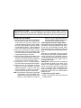
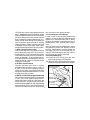
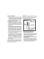
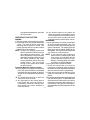
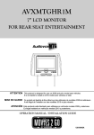
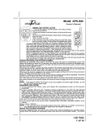
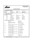
Model/Modèle/Modelo AA-939
REMOTE CONTROL AUTO SECURITY SYSTEM WITH STARTER INTERRUPT,
PARKING LIGHT FLASH AND BUILT IN 2 STAGE SHOCK SENSOR
SYSTÈME ANTIVOL À TÉLÉCOMMANDE AVEC BLOCAGE DU DÉMARREUR, CLIGNOTEMENT
DES FEUX DE POSITION ET DÉTECTEUR D'IMPACT À 2 NIVEAUX INTÉGRÉ
SISTEMA DE SEGURIDAD PARA AUTOMÓVILES A CONTROL REMOTO, CON
DESACTIVACIÓN DEL ARRANCADOR, DESTELLO DE LUCES DE ESTACIONAMIENTO
Y DETECTOR DE CHOQUE INCORPORADO DE 2 ETAPAS
INSTALLATION GUIDE & OWNER’S MANUAL
GUIDE D'INSTALLATION ET MANUEL D'UTILISATION
GUÍA DE INSTALACIÓN Y MANUAL DEL USUARIO
This device complies with part 15 of the FCC rules. Operation is subject to the following two conditions;
(1) This device may not cause harmful interference, and (2) This device must accept any interference received, including
interference that may cause undesired operation.
Ce dispositif est conforme à la partie 15 du Règlement de la FCC. L'utilisation est soumise aux deux conditions suivantes :
(1) Ce dispositif ne doit pas émettre de brouillage nuisible et (2) il doit accepter toute interférence reçue, y compris celles
susceptibles de provoquer un fonctionnement indésirable.
Este dispositivo cumple con la parte 15 de las reglas de la FCC. El funcionamiento está sujeto a las dos siguientes condiciones:
(1) este dispositivo no puede causar interferencias nocivas, y (2) este dispositivo debe aceptar cualquier interferencia que reciba,
incluyendo aquellas que puedan llegar a causar un funcionamiento no deseado.
CONGRATULATIONS On the purchase of your new Audiovox Alarm System.
Taking a few minutes to read this installation and owners guide will provide you
with the detailed information concerning all the features of your new alarm system.
MOUNTING THE SIREN:
plastic or a non grounded surface,
connect the Black siren ground wire as
described in the following section.
2. Mounting the Override Toggle Switch
Select a flat area on the lower dash lip, where
the switch is readily accessible to the driver,
but will not be accidentally bumped. Other
alternate locations are on the driver’s side kick
panel, or the side of the lower steering column
cover.
Since this is a “protected” ( will only operate
when the key is in the ignition ) bypass switch,
it does not have to be concealed, however
concealing the switch is always recommended,
as this provides an even higher level of
security to the vehicle.
IMPORTANT ! Make sure there is adequate
room behind the panel for the body of the
switch in the selected location. You should
also be sure that the drill will not pierce any
wires, or damage other components after
passing through the panel. It is always best to
remove the panel from the vehicle before
drilling the hole.
To mount the override switch;
A. Drill a 1/4" diameter hole in the selected
switch location.
1. Choose a location in the engine compartment
that is away from hot and moving parts,
considering the Red wire length must
connect to a battery positive source. Mount
the siren high enough to prevent access
from below the vehicle. Typical locations
are the inner fender well or the rear firewall.
2. Once you've selected a location, inspect
behind the area to ensure that drilling the
two holes required to mount the bracket will
not penetrate wiring or fluid lines.
3. Using the siren bracket as a template, mark
the two mounting holes with a scribe or
punch at your chosen location and drill two
3/16" holes on the pre-selected marks.
4. Using the two 1/4" x 1" screws supplied,
secure the siren mounting bracket in place.
5. Mount the siren to the bracket as shown
using the two nuts, washers, and lock
washers provided. Point the siren horn
(front) downward to allow the sound to
easily escape the engine compartment.
Note: If the bracket is mounted to a grounded
metal surface, secure the Black siren
ground when mounting the siren to the
bracket. If the bracket is mounted to
-2-
B. Pass the switch through the hole from
behind the panel, and secure from the front
using the split lockwasher and hex nut
provided.
The relay will be mounted in the passenger’s
compartment. Mount the relay close to the
wires from the ignition switch.
To mount the relay;
A. Screw the relay to the mounting surface,
using a sheet metal screw through the
hole in the relay mounting tab.
B. Secure the relay to an existing wire harness
or other component using cable ties.
TOGGLE SWITCH
WIRING THE SYSTEM
HEX NUT
SPLIT LOCKWASHER
DRILL A 1/4" DIAMETER HOLE
Mounting the Starter Interrupt Relay
SHEET METAL
SCREWS
RELAY
MOUNT INSIDE
PASSENGER'S
COMPARTMENT
RELAY
WIRE TIE TO EXISTING
HARNESS IN VEHICLE
-3-
Making the connections to the vehicle, as
described in this wiring section, may be
beyond the technical abilities of the average
consumer. If you have any questions with the
wiring procedures, please call a qualified
automotive technician, or call the AUDIOVOX
HOT LINE at 1-800-225-6074. Prior to making
any connections, a 12 Volt logic probe should
be used to confirm the proper connection point.
IMPORTANT ! The 9 pin white connector on
the end of the main harness that plugs into the
siren control module should remain disconnected
during the wiring portion of the installation.
Leaving this disconnected will ensure that the
keychain transmitters are properly programmed
later in the installation.
Routing The Wiring Harness
The GRAY, ORANGE, and YELLOW wires
must be routed through the firewall and into the
passenger compartment of the vehicle. The
ORANGE wire should be routed toward the
Starter Interrupt Relay harness. The GRAY
wire will be routed to the override switch. The
YELLOW wire will be routed toward the fuse
panel. Caution should be used when routing
wires. Keep wires away from all hot surfaces,
and any moving parts of the vehicle (radiator
fans, accelerator or brake pedal linkage, etc.).
When routing wires through the firewall, be
sure to pass the wires through an existing
rubber grommet. Failure to do this can result
in damage to wires from sharp metal edges,
and an eventual failure of the security system.
1. RED: (12 Volt Positive Input)
Connect the Red wire of the siren to Positive
post of the battery using the 5/16" ID ring terminal as shown. If your vehicle has side mount
main battery terminals, it will be necessary to
locate an alternate + 12 volt constant source.
If you are unfamiliar with automotive wiring, it
would be best to consult your dealer before
making this connection.
2. BLACK: (Ground Input)
Connect the Black siren wire to a clean
grounded metal part of the vehicle. Drill a 1/
8" hole in your chosen mounting location,
scrape off any paint or grease from the area
and secure the ground wire with the 1/4" ring
terminal and screw provided.
3. WHITE: (12 Volt Parking Light Flash Output)
Gain access to the wires coming from the back
of one of the front parking lamp sockets.
Switch the parking lights on, and locate the
wire that shows + 12 volts on the logic probe.
Switch the parking lights off, and verify that this
wire now shows 0 volts. Connect the WHITE
wire from the alarm to this wire, and insulate
-4-
the connection with electrical tape.
4. Connecting the YELLOW wire
Locate a fuse in the vehicle’s fusebox that
shows + 12 volts on the logic probe when the
ignition key is switched to the “ON” or “RUN”
position, and shows 0 volts when the key is
switched to the “OFF” position (radio or wiper
fuse).
After you have located a suitable fuse, switch
the ignition key to the “ON” position, remove
the fuse, and probe the contacts where the
fuse plugs into. One of the contacts will not
show 12 volts on the logic probe; this is where
the YELLOW wire will be connected.
Connection Method A;
A. Locate the wire coming from this fuse
terminal at the back of the fusebox.
B. Splice the YELLOW wire from the harness
to this wire and insulate with electrical tape.
YELLOW WIRE
SPLICE INTO WIRE AND WRAP
WITH ELECTRICAL TAPE
A
FUSE BOX
RADIO FUSE,
WIPER FUSES, ETC.
FUSE CLIP TERMINAL
(NOT INCLUDED)
YELLOW WIRE
B
Connection Method B;
A. “Fuse clip” terminals, which will plug in
with the contacts of the fuse, are available
at most electronics stores. This method of
connection may be easier in some vehicles.
B. Refer to the specific instructions included
with the fuse clip terminals.
5. ORANGE: (Starter Inhibit Relay Output)
a. Connect the ORANGE wire from the relay
harness to the ORANGE wire from the main
harness. Be sure to insulate this splice with
electrical tape.
b. Gain access to the wires coming from the
ignition switch. Connect the RED wire from
the relay harness to the wire from the
ignition switch that shows + 12 volts on the
logic probe when the key is switched to the
“ON or RUN” and “START” positions, and
shows 0 volts when the key is switched to
the “OFF” position. Be sure to insulate this
connection with electrical tape.
c. Locate the wire coming from the ignition
switch that shows + 12 volts on the logic
probe when the starter motor is cranking,
and shows 0 volts when the key is switched
to the “OFF”, “ACCESSORY”, and “ON or
RUN” positions. Cut this wire and try to start
the vehicle to verify that the starter motor
will not engage.
Connect the WHITE w/ BLACK stripe wire
from the relay harness to one side of the cut
starter wire, and connect the BLACK wire to
the other side of the cut wire.
CAUTION ! Be sure these wires are securely
connected, and properly insulated. If this
connection separates, the vehicle will not start,
even when using the ignition key.
ORANGE WIRE-SPLICE TO
ORANGE WIRE FROM
SIREN MODULE HARNESS
CONNECT BLACK
TO ONE SIDE OF
THE START WIRE
STARTER CUT
RELAY
CONNECTION
RED WIRE-SPLICE TO
THE IGNITION WIRE
CONNECT WHITE w/BLACK STRIPE WIRE
TO OTHER SIDE OF START WIRE
6. GRAY: (Override Switch Input)
a. Connecting the GRAY wire
Connect the GRAY wire from the main
harness to the Black/White wire from the
Override Switch. Be sure to insulate this
connection with electrical tape.
b. Connecting the BLACK wire from the
Override Switch
Connect the BLACK wire from the Override
Switch to a solid, grounded, metal part of
the vehicle. It can be connected to any
metal, non-painted bolt that screws into
the inner frame in the kick panel.
-5-
COMPLETING THE INSTALLATION
You will notice (3) additional wires, which
come directly out of the rubber wire exit boot
from the siren control module, and are not part
of the main harness. These wires are used to
customize the installation, and are required in
some vehicles.
1. Thin BLACK Wire
This is the antenna wire for the receiver that is
built into the siren control module. Fully extend
this wire, and route it as high in the engine
compartment as possible, for maximum
transmitter range.
GREEN LOOP:
The Green loop wire controls the voltage
sensor. Cutting this wire loop will prevent the
circuits voltage sensor from detecting voltage
drops such as the interior light turning on when
the door is opened. This wire should remain
connected unless your vehicle has circuitry
that remains powered when the vehicle is
turned off. Examples of vehicle circuits that
will necessitate cutting the Green loop wire
are automatic load leveling shocks, electric
analog clocks, on board computers that update
their information on a regular basis. If you
experience false triggers after installation of your
alarm system, it may be necessary to delete
the voltage sensor. In such situations, the level
of protection is minimized and relies strictly
on the vibration detector. It may be necessary
to increase the sensitivity of the vibration
sensor. To do so see the section on adjusting
the shock sensors for optimum results.
WHITE LOOP:
The White loop wire controls the voltage
sensors arming delay. Vehicles with circuits
that remain on after the ignition switch is turned
off will require a delay before arming. Cutting
the white loop wire will delay the voltage
sensor's arming delay from 3 seconds to 5
minutes. This additional delay will allow any
active circuit in the vehicle to turn off before
the voltage sensor is capable of detecting
voltage drops. This will allow you to arm the
unit immediately when exiting the vehicle, once
the vehicle’s electrical circuit stabilizes, the
alarm will fully arm sometime later.
PROGRAMMING THE TRANSMITTERS:
Your AA-939 Security System can program up
to two Audiovox code learning transmitters. To
program the transmitters, disconnect power to
the alarm for 10 seconds. Reconnect power
and within 10 seconds, press button #1 of the
first transmitter to be programmed. The siren
will chirp indicating the transmitter has been
programmed. Within 5 seconds of the first
programmed transmitter, press button #1 of
the second transmitter to be programmed.
The siren will chirp indicating the second transmitter has been programmed.
NOTE: If the vehicle battery is disconnected,
or the alarm loses power, the
transmitters programming WILL NOT
remain in memory. In such instances,
re-programming the transmitters is
necessary to operate the alarm. To
-6-
re-program the transmitters, repeat the
above procedure.
OPERATING YOUR SYSTEM:
ARMING:
1. Exit your vehicle, and close all entry points.
2. Press button #1 of your keychain transmitter
1 time. The siren will emit a single tone
indicating that the system is armed. The
parking light will flash once and the starter
inhibit relay will be engaged.
NOTE: Pressing the arming button twice
within 3 seconds will allow the unit to
arm without the shock sensor. This
will be indicated by a single chirp tone
followed by a single lower pitch chirp
tone. When operating in this mode,
the only detection means will be the
voltage sensor. The next normal
arming of your system will re-instate
the shock sensor.
Protection While the System is Armed
A. Opening a door (or any light activated entry
point), will cause the alarm to immediately
sound and the parking lights will flash on
and off for the complete 60 second alarm
cycle.
B. Any unauthorized attempt to start the
vehicle will be prevented.
C. Any light impact to the vehicle glass or
body panels will cause the system to
immediately sound the warning chirp,
discouraging any further attempts to
enter the vehicle.
-7-
D. Any forceful impact to the vehicle will
cause the system to immediately trigger
for the complete 60 second alarm cycle. At
the end of the cycle, the alarm will re-arm
itself, and resume monitoring the vehicle.
DISARMING:
1. As you approach your vehicle, press button
#1 of your keychain transmitter 1 time. The
siren will emit two chirps indicating that the
system is disarmed. The parking lights will
flash twice and the starter inhibit will be
disengaged. You may now enter and operate
your vehicle in a normal manner.
NOTE: If you heard four chirp tones upon
disarm and the parking lights flash
three times, this indicates that the
system had been triggered in your
absence. Carefully inspect your vehicle
for break in or physical damage.
If your system fails to operate as above:
1. Check and ensure that your keychain
transmitter is operating properly and that
the small LED on the transmitter illuminates
when a transmitter button is depressed.
2. Check and ensure that the Red wire of the
system is connected to a +12 volt battery
source.
3. Be certain that the transmitters are programmed
into your alarm system. If power had been
disconnected from the alarm or the vehicle
main battery had been disconnected, it is
necessary to re-program the transmitters.
See transmitter programming section of this
manual.
of your automotive wiring experience. If you
are uncertain of this procedure, consult your
dealer or qualified mechanic before attempting
to re-wire the voltage sensor RED wire
through the firewall to increase the voltage
sensor's level of detection.
TESTING THE VOLTAGE SENSOR:
1. Arm the alarm system by pressing button
#1 of a programmed transmitter one time.
The siren will chirp once confirming that the
system is armed.
2. Wait 4 seconds to allow the unit to stabilize.
3. Open any light activated entry point, the
siren will immediately trigger.
4. Turn the alarm system off by pressing button
#1 of a programmed transmitter one time.
5. Repeat the above procedure for each light
activated entry point.
If the unit fails to operate review the following
section concerning voltage sensor adjustment.
TESTING THE SHOCK SENSOR:
NOTE: The shock sensor incorporated in your
AA-939 security system operates on
two levels in any sensitivity range. The
warn away (pre-detect) stage operates at 30% less shock (vibration)
than the full trigger stage.
1. Arm your security system and allow the unit
to stabilize.
2. Strike the windshield support pillar with the
palm of your hand, the unit will emit a short
chirp from the siren. This is the warn away
(pre-detect) stage.
3. Striking the support pillar firmly will cause
the siren to sound. This is the full trigger
stage.
4. Repeat the above procedure from various
support areas of your vehicle, Bumpers, B
Pillars, etc.
If your system fails to operate as described,
review the following section concerning shock
sensor adjustment.
VOLTAGE SENSOR:
In most instances, connecting the Red siren
wire to the vehicle battery will provide adequate
voltage sensing. If your vehicle does not trigger when the door is opened and the interior
light turns on, it may be necessary to increase
the voltage sensor's level of detection. Before
making this wiring change, confirm that the
interior light is in good working order and
illuminates when any door is opened. If your
interior light works properly, and the unit does
not trigger, the Red wire will have to connect
to a +12 volt source closer to the interior light.
This may necessitate moving the Red wire to
the interior of the vehicle and connecting to
the interior light fuse. Routing the Red wire
through a firewall grommet and connecting to
the interior light fuse may be beyond the scope
SHOCK SENSOR ADJUSTMENT:
The shock sensor of the AA-939 security
system is electronically adjusted and is capable
-8-
of 8 different sensitivity levels. To adjust or
change the setting of your shock sensor disarm the system and within 8 seconds, simultaneously press both buttons of your transmitter until the siren emits a low tone. This indicates that the unit is ready to accept a sensitivity level change. Press button #2 of your
transmitter to make adjustments. The siren
will emit a tone synonymous with the changing levels. The lower the tone, the lower the
setting, the higher the tone, the higher the setting. While in the adjustment mode, strike a
support pillar of the vehicle, the unit will emit a
2 second tone indicating your setting. The
system will allow you to keep this setting or
make further adjustments. Once you have
reached the desired level, press button #1 to
lock in your setting. The siren will emit two
high chirps to confirm your setting is locked.
Follow steps 1-4 above to test the sensitivity
level change.
Remote Panic Operation
The alarm can be activated via the keychain
transmitter to draw attention to your vehicle
during an emergency situation.
To activate the panic feature;
A. Press and hold the arm/disarm button on
the keychain transmitter for 3 seconds.
B. The alarm will sound, flash parking lights
and continue for 60 seconds.
C. To silence the alarm before the 60 second
shutdown, press and release the arm/
disarm button on the keychain transmitter.
WARNING ! In most areas, it is illegal to
activate the alarm while the vehicle is moving.
For the safety of your passengers and other
motorists, do not activate the alarm while your
vehicle is in motion.
Override Switch Operation
If you lose or misplace your keychain transmitter,
or if the transmitter fails to disarm the system,
an emergency bypass switch is included to
temporarily disarm the system.
To use the switch;
A. Open the driver’s door. The alarm will sound !
B. Insert the key into the ignition switch, and
turn it to the “on” position.
C. Move the override switch to the “on” then
“off” position. The alarm will disarm, and
the vehicle can now be started.
INSTALLING THE WARNING DECALS:
Once you have confirmed the operation of your
security system, you may elect to install the
security systems warning decals. Typically
these decals are installed on the lower left of
the driver side and lower right of the passenger side windows as shown. Remove the decal backing paper and hold the ends of the
decal toward you. This will cause the center
to bend toward the window. Place the center
of the decal on the window and roll the sides
out one at a time. This will insure no air
bubbles get under the decal when affixing it to
the window. Once in place, smooth out the
entire label pressing it firmly to the window.
-9-
OPERATION AT A GLANCE:
TRANSMITTER OPERATION
SYSTEM RESPONSE
PRE - CONDITION
PRESS BUTTON #1 1 TIME
ARMS OR DISARMS ALARM
PRESS BUTTON #1 2 TIMES
DELETE SHOCK SENSOR
FUNCTION
PRESS BUTTON #1 FOR 3
SECONDS
PANIC MODE
PRESS BOTH BUTTONS FOR 2
SECONDS
SHOCK ADJUST MODE
SYSTEM MUST FIRST
BE DISARMED
SYSTEM MUST FIRST
BE DISARMED
AUDIBLE + VISIBLE STATUS INDICATIONS:
1 CHIRP AND 1 PARKING LIGHTS FLASH
= SYSTEM ARMED
2 CHIRPS 2 PARKING LIGHTS FLASH
= SYSTEM DISARMED
4 CHIRPS 3 PARKING LIGHTS FLASH
= SYSTEM DISARMED AND HAD
BEEN TRIGGERED
WIRE LOOP CONFIGURATION
WIRE LOOP
CLOSED (NOT CUT)
OPEN (CUT)
GREEN
VOLTAGE SENSOR
OPERATIONAL
VOLTAGE SENSOR
NON OPERATIONAL
WHITE
3 SECOND VOLTAGE
SENSE DELAY
5 MINUTE VOLTAGE
SENSE DELAY
-10-
-11-
12 MONTH LIMITED WARRANTY
Applies to control modules, relays, transmitters, sensors, and sirens.
AUDIOVOX CORPORATION (the Company) warrants to the original retail purchaser of this product that should
this product or any part thereof, under normal use and conditions, be proven defective in material or
workmanship within 12 months from the date of original purchase, such defect(s) will be repaired or replaced
(at the Company's option) without charge for parts and repair labor.
To obtain repair or replacement within the terms of this Warranty, the product is to be delivered with proof of
warranty coverage (e.g. dated bill of sale), specification of defect(s), transportation prepaid, to an approved
warranty station or the Company at the address shown below.
This Warranty does not cover costs incurred for removal or reinstallation of the product, or damage to vehicle
electrical systems.
This Warranty does not cover batteries nor apply to any product or part thereof which, in the opinion of the
Company, has suffered or been damaged through alteration, improper installation, mishandling, misuse,
neglect, accident, or by removal or defacement of the factory serial number/bar code label(s).
This Warranty is in lieu of all other express warranties or liabilities. ANY IMPLIED WARRANTIES, INCLUDING
ANY IMPLIED WARRANTY OF MERCHANTABILITY, SHALL BE LIMITED TO THE DURATION OF THIS
WRITTEN WARRANTY. ANY ACTION FOR BREACH OF ANY WARRANTY HEREUNDER INCLUDING ANY
IMPLIED WARRANTY OF MERCHANTABILITY MUST BE BROUGHT WITHIN A PERIOD OF 30 MONTHS
FROM DATE OF ORIGINAL PURCHASE. IN NO CASE SHALL THE COMPANY BE LIABLE FOR ANY
CONSEQUENTIAL OR INCIDENTAL DAMAGES FOR BREACH OF THIS OR ANY OTHER WARRANTY,
EXPRESS OR IMPLIED, WHATSOEVER. No person or representative is authorized to assume for the
Company any liability other than expressed herein in connection with the sale of this product.
The Company does not warrant that this product cannot be compromised or circumvented. THE EXTENT OF
THE COMPANY'S LIABILITY UNDER THIS WARRANTY IS LIMITED TO THE REPAIR OR REPLACEMENT
PROVIDED ABOVE AND, IN NO EVENT, SHALL THE COMPANY'S LIABILITY EXCEED THE PURCHASE
PRICE PAID BY PURCHASER FOR THE PRODUCT.
Some states do not allow limitations on how long an implied warranty lasts or the exclusion or limitation of
incidental or consequential damage so the above limitations or exclusions may not apply to you. This Warranty
gives you specific legal rights and you may also have other rights which vary from state to state.
U.S.A. : AUDIOVOX CORPORATION, 150 MARCUS BLVD., HAUPPAUGE, NEW YORK 11788 l
1-800-645-4994
CANADA: CALL 1-800-645-4994 FOR LOCATION OF WARRANTY STATION SERVING YOUR AREA
128-5813
© 2000 Audiovox Corp., Hauppauge, N.Y. 11788
128-5791A