1
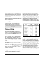
S E T - U P
M A N U A L
F O R
T H E
STATEMENT SYSTEM
Contents
System Set-up
Checklist
The Statement system consists of the following items:
Introduction
2
System Set-up
2
Room Acoustics
6
Troubleshooting
8
2 - electrostatic panels mounted in frames
2 - electrostatic panel pedestals with uprights
2 - interface modules
4 - interface riser blocks
2 - woofer columns
2 - crossover modules*
2 - crossover power supplies*
1 - toolkit
4 - power cords*
* Add two more if system is balanced.
Before setting-up the system, please make note that
odd serial numbers for all components (woofer tower,
stator, interface, crossover, power supply (example:
XICL001)) are matched for use as the right channel,
while even serial numbers for all components are
matched for the left channel.
Woofer Assemblies
Introduction
Congratulations! You are about to experience the
highest resolution, most dynamic, extended soundstage system in the galaxy, the Statement!
The Martin-Logan STATEMENT represents the
culmination of an intensive, dedicated group research
program directed toward establishing a world class
reference system utilizing leading-edge technology,
without compromising durability, reliability, craftsmanship, or aesthetic design.
As a result of our continuous research and development program here at Martin-Logan, we decided that it
was time to incorporate some of our latest technologies into a reference product.
Page 2
The woofer assemblies are connected to the amplifier
via either the 5-way binding posts or screw terminals on
the backplate of the woofer column. As can be seen from
the back panel of the Statement woofer, the signal
connectors are strapped in such a way that you can use
one amplifier out of the box.
If you desire or require double amplification, the electronic
crossover modules have dual, low-level, low-pass,
outputs. By removing the straps on the woofer backplate
you can directly access, via one set of 5-way binding
posts, two woofers at a time. Hence you are able to use
two bass amplifiers. This option is available for the
consideration of amplifiers which do not perform their best
into a 2 ohm load. When using two amplifiers, each one
will see only a 4 ohm load.
Electrostatic PPanel
anel Assemblies
The electrostatic panel assemblies should first be
assembled mechanically. The method of assembly
consists of setting the pedestal on the floor then sliding
the left and right upright braces on to their hidden
fasteners. Observe figure 1. Next, bring the electrostatic
panel assembly to the braces and attach via the hidden
fasteners. Finally, attach the interface riser blocks via the
hidden fasteners and install the interface module on-top
of the risers.
STATEMENT Set-up Manual
You are now ready to connect the electrostatic panel to
the interface module via the three color coded pin-plugs.
Naturally, black to black, green to green and red to red.
The blue stat panel wire goes to the green pin-plug on
the interface module.
Observing from the back of the interface module you will
see five-way binding posts, screw terminals, soft-contour
switches, and the AC input.
Proceed by plugging in the AC power cord, first at the
interface module, then to the wall outlet. Then attach to
your high-pass amplifier via the screw terminals or the
five-way binding posts. They are internally parallel
connected so that either terminal set may be used.
Do not use both with different power amplifiers!
Use only one!
Crossover Settings
Before you connect the crossover and begin listening,
there are some internal switches that must be set.
However, if you are using identical amplifiers for the high
and low pass sections of the Statement, you may skip
this step.
Remove the covers from the crossover modules that
have the control knob. Inside you will see, towards the
back, two red dip switches. The left dip switch as you
face the crossover attenuates the low pass, the right dip
switch attenuates the high-pass. These switches will
balance the gain in amplifiers with different gain characteristics.
The following formula will help you calculate the gain of
each amplifier:
Amplifier Gain = 20 log
(Rated Output @ 8 ohms) x 8
Input Sensitivity
Below is a list of switch settings to help you select the
proper gain switch settings.
As you detent the switch towards the rear jacks, you are
engaging that switch. In other words, you are turning the
transducer down by 1 decibel per position as you detent
the switch in numerical order away from1. In order to
STATEMENT Set-up Manual
properly engage a switch, you need to have all other
switches opposed away from the rear jacks (off - one
switch on at a time). Begin by setting both the low-pass
and the high- pass in the number one position. If the
high-pass and low- pass amplifiers have the same gain,
the system is designed to operate with both dip switches
set to “1” (Position “1” represents no attenuation). If the
gain difference is known, attenuate the higher gain
amplifier by the known gain difference using the switch
one number higher than the attenuation needed in dB (Ie:
switch “4” is 3db attenuation-all switches open is 8dB
down).
OPEN
CLOSED
ATTENUATION
Does not matter.
1
1,3,4,5,6,7,8
1,2,4,7,8
1,2,4,5,6,7,8
1,2,3,5,7,8
1,2,3,5,6,7,8
1,2,3,4,6,8
1,2,3,4,6,7,8
1,2,3,4,5,7
1,2,3,4,5,7,8
1,2,3,4,5,6,8
1,2,3,4,5,6,7
1,2,3,4,5,6,7,8
1
2,3,4,5,6,7,8
2
3,5,6
3
4,6
4
5,7
5
6,8
6
7
8
None
0 dB
-0.5 dB
-1.0 dB
-1.5 dB
-2.0 dB
-2.5 dB
-3.0 dB
-3.5 dB
-4.0 dB
-4.5 dB
-5.0 dB
-6.0 dB
-7.0 dB
-8.0 dB
If equipped, the best way now to obtain the optimal
setting is to locate a spectrum analyzer in the room near
your seating position, turn one system on with pink noise
and begin to observe the relationship of the stat panel
and the subwoofer at the crossover point approximately
at 100 Hz. When you begin to see the spectrum becoming correct at that point, that is when you have the optimal
crossover format. By correct, I mean flat, or even. The
energy below 100 Hz is roughly comparable to the energy
above 100 Hz. You should have reasonable tonal
balance from 60 Hz onward to 200 Hz. At that point you
have the optimal frequency balance at the crossover
point. Keep in mind that specs and equipment can
determine the best place to begin, but your ears are the
most critical instrument available. Listen and adjust for
your personal best balance.
Page 3
System Set-up
Crossover Modules
Contour "A"
You will notice that one of the crossover modules has
red-banded Tiffany RCA connectors while the other unit
has white. The red denotes the right channel module
while white denotes the left. Stack the two crossover
modules, with the control knobs, on top of each other and
the two power supplies on top of each other. Then
connect each power supply with each crossover via the
supplied Neutriks power connectors.
You engage contour A by switching the Activation switch
from bypassed to engaged and switching the Contour
switch to A. Contour A allows approximately a one dB
attenuation from 500 Hz to 10,000 Hz. This allows the
integrity of the midrange to remain intact and the top-end
extension to remain intact but eliminates the appearance
of brightness.
Insert your pre-amps' output cables into the crossovers'
Main Input jacks, your low-pass amplifiers' cables into
the crossovers' Low Output jacks, and your high-pass
amplifiers' cables into High Output jacks.
Once this is done, you may connect the crossover power
supply modules to AC power.
CAUTION !
DO NOT CONNECT THE POWER SUPPLIES AND
CROSSOVERS VIA THE NEUTRIKS CONNECTORS
AFTER PLUGGING IN THE AC MAINS!
Plug in AC mains only after the power supplies and
crossovers have been connected together. Make sure
the power amplifiers are off.
Tone Shaping Controls
The Tone Shaping controls are located on the rear of the
interface modules. Begin your listening session with the
Activation switch in the bypassed mode. The bypassed
mode means that you are now running the system in an
absolute flat position and there is no contouring available. You will notice that the system is extremely high in
resolution and if you have a live room or a bright frontend, you may find one of the contour modes to be more
listenable. Listen for massed strings and cymbal tones.
If they are bright, the contour switch can be used to
smooth out this area. Generally the contour positions
are not needed unless a bright front-end or bright room
is in the system.
Page 4
Contour "B"
If your room or your front-end is considerably bright, then
contour B may prove more effective. Contour B is another
decibel of attenuation in the same region, but will create
even more of the condition established by contour A.
Again, begin all listening in the bypassed mode. It is
recommended that you spend at least a day or two with
the Activation switch set to bypassed before experimenting with any of the contour positions.
“F
un-factor ” Control
“Fun-factor
First adjust control knobs on the front panel so that each
knob is positioned horizontally (see illustration). This will
mean that the system is 1.5 dB
in its EQ below 50 Hz.
You will notice a control
knob on the front of each
crossover module. That
control effects the energy
of the system below 50
Hz. Look at the enclosed
diagram to observe the
positioning of the switch. This is allowed to either
enhance or decrease energy below 50 Hz to accommodate different placement in the room. The adjustment
range is from -3dB to +6dB with the 4th position clockwise being flat.
STATEMENT Set-up Manual
Placement
Placement is a very important part of the set up procedure.
We recommend that you start with the system roughly
two meters from the wall behind the speakers, woofers
on the outside of the stat panels, woofer fronts flush with
and beside the stat panel frame fronts. Recommended
toe-in is 10 degrees or less. Narrow rooms may require
the woofers to be on the inside of the stat panels. Soundstage and imaging are affected by the relative placement
of the woofers with respect to the stat panels. The woofer
columns may be moved back half way between the stat
panels and the wall, however, this will affect the bass
response, time alignment, and woofer/stat panel relative
levels. Crossover settings may need re-adjustment.
Also, even though the best results seem to occur with the
stat panel cable connector polarity dots up, time alignment variations may warrant experimentation with
inverting the stat panel polarity (red dot down).
We have found that, generally, the best performance
results with the woofers positioned close to the left and
right walls and to the outside of the stat panels.
Narrow Rooms
A narrow room almost dictates that the woofers will be to
the inside of the stat panels. Experiment with the
position that results in the widest soundstage, tightest
and most extended bass, and the best balance at the
lower midrange area.
Wide Rooms
You have more room to experiment here. Place your stat
panels for the best soundstage. You will find that they
can be placed quite far apart and still provide excellent
middle center staging with the stage width extending
beyond the outer edges of both stat panels. Initially, try
placing the woofers to the outside of the stats, close to
the side walls.
W oofer/R
oom Interaction
oofer/Room
vs.Time Alignment
The crossover is provided at 125 Hz so you have some
latitude for movement without much trade-off regarding
imaging. However, you will find dramatic changes
regarding woofer/room placement.
The most extended bass response generally occurs
when placing the woofers at the corners of the room,
however a horn effect can occur affecting the lower
midrange area. If the woofer is placed between the stats,
generally a prominence in the upper bass will occur due
to rear wall reflection enhancement, with a recession in
the lower bass (your “Fun Factor Control” will solve this
problem).
It is for the above reasons that we recommend your
starting position begin with the woofers to the outside
and parallel with the frontal plane of the stats. Once you
have established a reference listening condition, begin to
experiment and don’t be afraid to move the woofer tower
all over the back wall area.
R oom TTreatment
reatment
Room treatment is a crucial part of the system set up.
We recommend experimentation with sound absorbing
panels and/or diffusers. It is most important to avoid
sonic glare from reflections off the wall behind the
speakers and behind the listener. Consider, however,
that too much acoustic treatment may cause the system
to sound too dry. We have found that a 2' wide panel 6'
tall placed directly behind the stat panel on the wall can
be very effective without damping the sound too much.
Experimenting with center dampers such as the ASC half
rounds on the wall between the speakers can enhance
center staging.
Experimenting with damping on the back wall, if it is
close to the listening position, can also help establish a
superior imaging condition.
Experimenting with damping on the side walls directly to
the side of the stat panels, particularly in narrow rooms,
can result in superior imaging and reduced “glare” in
conditions where the room and wall surfaces are hard.
STATEMENT Set-up Manual
Page 5
Room Acoustics
Your Room
This is one of those areas that requires a
little background to understand and some
time and experimentation to obtain the best
performance from your system.
Your room is actually a component and an
important part of your system. This component is a very large variable and can
dramatically add to, or subtract from, a great
musical experience, depending on how well
you attend to it.
All sound is composed of waves. Each note
has its own wave size, with the lower bass
notes literally encompassing from 10' to as
much as 40'! Your room participates in this
wave experience like a 3 dimensional pool
with waves reflecting and becoming
enhanced depending on the size of the
room and the types of surfaces in the room.
Remember, your audio system can literally
generate all of the information required to
recreate a musical event in time, space,
and tonal balance. The purpose of your
room, ideally, is to not contribute to that
information. However, every room does
contribute to the sound and the better
speaker manufacturers have designed their
systems to accommodate this phenomenon.
Let’s talk about a few important terms before we begin.
Terminology
Standing Waves. The parallel walls in your room will reinforce certain
notes to the point that they will sound louder than the rest of the
audio spectrum and cause “one note bass”, “boomy bass”, or
“tubby bass”. For instance, 100Hz represents a 10' wavelength.
Your room will reinforce that specific frequency if one of the
dominant dimensions is 10'. Large objects in the room such as
cabinetry or furniture can help to minimize this potential problem.
Some serious “audiophiles” will literally build a special room with
no parallel walls just to get away from this phenomenon.
Reflective Surfaces. The hard surfaces of your room, particularly if
close to your speaker system, will reflect those waves back into
the room over and over again, confusing the clarity and imaging of
your system. The smaller sound waves are mostly affected here
and occur in the mid and high frequencies. This is where voice
and frequencies as high as the cymbals can occur.
Near Field Reflections. Those reflective surfaces of the room that are
the closest to your speaker system, particularly if they are hard
surfaces, can reflect the musical energy back into the room,
confusing the imaging and tonal balance of your system. Excessive brightness can result from this condition and diffuse, ill
defined imaging can easily occur if too many surfaces near your
speakers are hard and sharp in their relative angle to your system.
Resonant Surfaces and Objects. All of the surfaces and objects in
your room are subject to the frequencies generated by your
system. Much like an instrument, they will vibrate and “carry on” in
syncopation with the music and contribute in a negative way to the
music. Ringing, boominess, and even brightness can occur
simply because they are “singing along” with your music.
Resonant Cavities. Small alcoves or closet type areas in your room
can be chambers that create their own “standing waves” and can
drum their own “one note” sounds.
Clap your hands. Can you hear an instant echo respond back ?
You have near-field reflections. Stomp your foot on the floor. Can
you hear a “boom”? You have standing waves or large panel
resonances such as a poorly supported wall. Put your head in a
small cavity area and talk loudly. Can you hear a booming? You
have just experienced a cavity resonance.
Page 6
STATEMENT Set-up Manual
Rules of Thumb
Bipolar Speakers and Your Room
Hard vs. Soft Surfaces. If one surface of your room
(wall, floor, ceiling) is hard, a good rule of thumb
suggests to try to have the opposing surface soft. So,
if you have a hard wall of glass or paneling on one
side of the room, it is best to have drapery or wall
hangings on the opposing wall. If you have a hard
ceiling, it generally is a good idea to have a soft floor
of carpeting or area rugs. Large, soft furniture also
counts to help damp a highly reflective room.
Martin-Logan electrostatic loudspeakers are known as
bipolar radiators. This means that they produce sound
from both their fronts and their backs. Consequently,
musical information is reflected by the wall behind them
and may arrive either in or out of step with the information
produced by the front of the speaker.
This rule suggests that a little reflection is good. As a
matter of fact, some rooms can be so “over damped”
with carpeting, drapes and sound absorbers that the
music system can sound dull and lifeless. On the
other hand, rooms can be so hard that the system
can sound like a gymnasium with too much reflection and brightness. The point is that balance is the
optimum environment.
Break-up Objects. Objects with complex shapes, such
as bookshelves, cabinetry, and multiple shaped
walls can help to break up those sonic gremlins and
diffuse any dominant frequencies.
Solid Coupling. Your loudspeaker system generates
frequency vibrations or waves into the room. This is
how it creates sound. Those vibrations will vary from
20 per second to 20,000 per second. If your speaker
system is not securely planted on the floor or solid
surface, it can shake as it produces sound, and
consequently the sound can be compromised. If
your speaker is setting on the carpet and only foot
gliders are used, the bass can be ill defined and
even boomy. Additionally, the imaging can be poorly
located and diffuse if the system is not on solid footing.
STATEMENT Set-up Manual
The low frequencies can either be enhanced or nulled by
the position from the back wall. Your Statements's have
been designed to be placed 3 feet from the back wall to
obtain the best results, however your room may see
things differently. So, listening to the difference of the
bass response as a result of the changes in distance
from the back wall can allow you to get the best combination of depth of bass and tonal balance.
The mid-range and high frequencies can also be
affected, but in a different way. The timing of the first wave
as it is first radiated to your ears and then the reflected
information as it arrives at your ears later in time, can
result in confusion of the precious timing information that
carries the clues to imaging and, consequently result in
blurred imaging and excessive brightness. Soft walls,
curtains, wall hangings, or sound dampeners (your
dealer can give you good information here) can be
effective if these negative conditions occur.
Page 7
Troubleshooting
Poor Imaging
No Output.
❐ Check that all your system components are turned on.
❐ Check placement. Are both speakers the same distance from the walls? Do they have the same amount
of toe-in? Try moving the speakers away from the back
and side walls.
❐ Check your speaker wires and connections.
❐ Check all interconnecting cables.
❐ Check the polarity of the speaker wires. Are they
connected properly?
Weak Output, Loss of Highs.
❐ Check the power cord. Is it properly connected to the
Popping and Ticking Sounds, Funny Noises
ESL?
❐ These occasional noises are harmless and will nut
hurt your audio system or your speakers. All electrostatic speakers are guilty of making odd noises at one
time or another.
Exaggerated Highs, Brightness.
❐ Check the toe-in of the speakers.
❐ These noises may be caused by dirt and dust particles
collecting on the speaker, by high humidity or by AC line
fluctuations that may occur in your area.
❐ Check the setting of the Soft Contour switch.
❐ Dirt and dust may be vacuumed off with abrush attach-
Muddy Bass
❐ Check placement. Try moving the speakers closer to
ment connected to your vacuum cleaner or you may
blow them off with compressed air.
the back and side walls.
❐ DO NOT SPRAY ANY KIND OF CLEANING AGENT ON
❐ Check the type of feet being used. Try attaching the
OR IN CLOSE PROXIMITY TO THEM.
coupling spikes.
Lack of Bass
❐ Check your speaker wires. Is the polarity correct?
2001 delaware street
p.o. box 741
lawrence, kansas 66044
ph: 913.749.0133
fax: 913.749.5320
telex: 262817 mlesl
Page 8
STATEMENT Set-up Manual