1
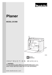
Portable Cut-Off
MODEL 2414NB
003753
DOUBLE
INSULATION
I N S T R U C T I O N
M A N U A L
WARNING:
For your personal safety, READ and UNDERSTAND before using.
SAVE THESE INSTRUCTIONS FOR FUTURE REFERENCE.
w w w. m a k i t a t o o l s. c o m
SPECIFICATIONS
Model
2414NB
Wheel diameter
355 mm (14”)
Hole diameter
25.4 mm (1”)
No load speed (RPM)
3,800 /min.
Dimensions (L x W x H)
500 mm x 280 mm x 600 mm
(19-3/4” x 11”x 23-5/8”)
Net weight
16.4kg (36.2 lbs)
• Manufacturer reserves the right to change specifications without notice.
• Specifications may differ from country to country.
For Your Own Safety Read Instruction Manual
Before Operating Tool
Save it for future reference
USA007-1
GENERAL SAFETY PRECAUTIONS
(For All Tools)
1. KNOW YOUR POWER TOOL. Read the
owner’s manual carefully. Learn the tool’s
applications and limitations, as well as the
specific potential hazards peculiar to it.
2. KEEP GUARDS IN PLACE and in working
order.
3. REMOVE
ADJUSTING
KEYS
AND
WRENCHES. Form habit of checking to
see that keys and adjusting wrenches are
removed from tool before turning it on.
6. KEEP CHILDREN AWAY. All visitors
should be kept safe distance from work
area.
7. MAKE WORKSHOP KID PROOF with padlocks, master switches, or by removing
starter keys.
8. DON’T FORCE TOOL. It will do the job better and safer at the rate for which it was
designed.
4. KEEP WORK AREA CLEAN. Cluttered
areas and benches invite accidents.
9. USE RIGHT TOOL. Don’t force tool or
attachment to do a job for which it was not
designed.
5. DON’T USE IN DANGEROUS ENVIRONMENT. Don’t use power tools in damp or
wet locations, or expose them to rain.
Keep work area well lighted. Don’t use
tool in presence of flammable liquids or
gases.
10. WEAR PROPER APPAREL. Do not wear
loose clothing, gloves, neckties, rings,
bracelets, or other jewelry which may get
caught in moving parts. Nonslip footwear
is recommended. Wear protective hair
covering to contain long hair.
2
11. ALWAYS USE SAFETY GLASSES. Also
use face or dust mask if cutting operation
is dusty. Everyday eyeglasses only have
impact resistant lenses, they are NOT
safety glasses.
12. SECURE WORK. Use clamps or a vise to
hold work when practical. It’s safer than
using your hand and it frees both hands
to operate tool.
13. DON’T OVERREACH. Keep proper footing
and balance at all times.
14. MAINTAIN TOOLS WITH CARE. Keep tools
sharp and clean for best and safest performance. Follow instructions for lubricating
and changing accessories.
15. DISCONNECT TOOLS before servicing;
when changing accessories such as
blades, bits, cutters, and the like.
16. REDUCE THE RISK OF UNINTENTIONAL
STARTING. Make sure switch is in off
position before plugging in.
17. USE RECOMMENDED ACCESSORIES.
Consult the owner’s manual for recommended accessories. The use of improper
accessories may cause risk of injury to
persons.
18. NEVER STAND ON TOOL. Serious injury
could occur if the tool is tipped or if the
cutting tool is unintentionally contacted.
19. CHECK DAMAGED PARTS. Before further
use of the tool, a guard or other part that
is damaged should be carefully checked
to determine that it will operate properly
and perform its intended function - check
for alignment of moving parts, binding of
moving parts, breakage of parts, mounting, and any other conditions that may
affect its operation. A guard or other part
that is damaged should be properly
repaired or replaced.
20. DIRECTION OF FEED. Feed work into a
blade or cutter against the direction of
rotation of the blade or cutter only.
21. NEVER LEAVE TOOL RUNNING UNATTENDED. TURN POWER OFF. Don’t leave
tool until it comes to a complete stop.
22. REPLACEMENT PARTS. When servicing
use only identical replacement parts.
23. POLARIZED PLUGS. To reduce the risk of
electric shock, this equipment has a
polarized plug (one blade is wider than
the other). This plug will fit in a polarized
outlet only one way. If the plug does not fit
fully in the outlet, reverse the plug. If it
still does not fit, contact a qualified electrician to install the proper outlet. Do not
change the plug in any way.
VOLTAGE WARNING: Before connecting the tool to a power source (receptacle, outlet,
etc.) be sure the voltage supplied is the same as that specified on the nameplate of the tool.
A power source with voltage greater than that specified for the tool can result in SERIOUS
INJURY to the user - as well as damage to the tool. If in doubt, DO NOT PLUG IN THE
TOOL. Using a power source with voltage less than the nameplate rating is harmful to the
motor.
3
USE PROPER EXTENSION CORD. Make sure your extension cord is in good condition.
When using an extension cord, be sure to use one heavy enough to carry the current your
product will draw. An undersized cord will cause a drop in line voltage resulting in loss of
power and overheating. Table 1 shows the correct size to use depending on cord length and
nameplate ampere rating. If in doubt, use the next heavier gage. The smaller the gage number, the heavier the cord.
Table 1: Minimum gage for cord
Volts
120 V
Ampere Rating
More Than
Not More Than
0
6
10
12
6
10
12
16
25 ft.
Total length of cord in feet
50 ft.
100 ft.
150 ft.
AWG
18
18
16
14
16
16
16
12
16
14
14
12
14
12
Not Recommended
SPECIFIC SAFETY RULES
USB078-1
DO NOT let comfort or familiarity with product (gained from
repeated use) replace strict adherence to portable cut-off safety
rules. If you use this tool unsafely or incorrectly, you can suffer
serious personal injury.
1. Wear hearing protection during extended
periods of operation.
2. Use only wheels having a maximum operating speed at least as high as “No Load
RPM” marked on the tool’s nameplate.
Use only fiberglass-reinforced cut-off
wheels.
3. Check the wheel carefully for cracks or
damage
before
operation.
Replace
cracked or damaged wheel immediately.
Run the tool (with guard) at no load for
about a minute, keeping tool away from
others. If wheel is flawed, it will likely separate during this test.
4. Secure the wheel carefully.
5. Use only flanges specified for this tool.
4
6. Be careful not to damage the spindle, the
flange (especially the installing surface)
or the bolt. Damage to these parts could
result in wheel breakage.
7. Do not operate the tool without guards in
place. Check wheel guard for proper closing before each use. Do not operate the
tool if wheel guard does not move freely
and close instantly. Never clamp or tie the
wheel guard into the open position.
8. Hold the handle firmly.
9. Keep hands away from rotating parts.
10. Make sure the wheel is not contacting the
workpiece before the switch is turned on.
11. Before using the tool on an actual workpiece, let it run for a while. Watch for
vibration or wobbling that could indicate
poor installation or a poorly balanced
wheel.
12. Watch out for flying sparks when operating. They can cause injury or ignite combustible materials.
13. Remove material debris from the area that
might be ignited by sparks. Be sure that
others are not in the path of the sparks.
Keep a proper , charged extinguisher
closely available.
15. Do not attempt to keep the trigger in the
ON position.
16. If the wheel stops during operation,
makes an odd noise or begins to vibrate,
switch off the tool immediately.
17. Turn off the tool and wait for the wheel to
stop before moving workpiece or changing settings.
18. Do not touch the workpiece immediately
after operation; it is extremely hot and
could burn your skin.
19. Store wheels in a dry location only.
14. Use the cutting edge of the wheel only.
Never use side surface.
SAVE THESE INSTRUCTIONS
WARNING:
MISUSE or failure to follow the safety rules stated in this
instruction manual may cause serious personal injury.
5
INSTALLATION
003800
Securing cut-off
This tool should be bolted with two bolts to a level and stable
surface using the bolt holes provided in the tool’s base. This
will help prevent tipping and possible personal injury.
1
2
1. Base
2. Bolt holes
FUNCTIONAL
DESCRIPTION
•
003754
CAUTION:
Always be sure that the tool is switched off and
unplugged before adjusting or checking function on the
tool.
Switch action
1
•
2
•
1. Lock-off button
2. Switch trigger
CAUTION:
Before plugging in the tool, always check to see that the
switch trigger actuates properly and returns to the “OFF”
position when released.
When not using the tool, remove the lock-off button and
store it in a secure place. This prevents unauthorized
operation.
To prevent the switch trigger from being accidentally pulled, a
lock-off button is provided.
To start the tool, depress the lock-off button and pull the
switch trigger. Release the switch trigger to stop.
003756
1
2
1. Screw
2. Spark guard
6
Spark guard
The spark guard is factory-installed with its lower edge contacting the base. Operating the tool in this position will cause
many sparks to fly around. Loosen the screw and adjust the
spark guard to a position at which minimum sparks will fly
around.
003757
1
Stopper plate
The stopper plate prevents the cut-off wheel from contacting
the workbench or floor. When a new wheel is installed, set
the stopper plate to position (A). When the wheel wears
down to the extent that the lower portion of the workpiece is
left uncut, set the stopper plate to position (B) to allow
increased cutting capacity with a worn down wheel.
(B)
(A)
1. Stopper plate
003758
1
The original spacing or interval between the vise and the
guide plate is 0 - 170 mm (0 - 6-11/16”). If your work requires
wider spacing or interval, proceed as follows to change the
spacing or interval.
2
3
Remove the two hex bolts which secure the guide plate.
Move the guide plate as shown in the figure and secure it
using the hex bolts. The following interval settings are possible:
4
1.
2.
3.
4.
Interval between vise and guide plate
Socket wrench
Guide plate
Move
Hex bolts
35 - 205 mm (1-3/8” - 8-1/16”)
003759
70 - 240 mm (2-3/4” - 9-7/16”)
•
003760
1
2
Setting for desired cutting angle
To change the cutting angle, loosen the two hex bolts which
secure the guide plate. Move the guide plate to the desired
angle (0° - 45°) and tighten the hex bolts securely.
3
•
1. Socket wrench
2. Guide plate
3. Hex bolts
CAUTION:
Remember that narrow workpieces may not be secured
safely when using the two, wider interval settings.
CAUTION:
Never perform miter cuts when the guide plate is set at
the 35 - 205 mm (1-3/8” - 8-1/16”) or 70 - 240 mm
(2-3/4” - 9-7/16”) position.
7
ASSEMBLY
•
003761
2
1
CAUTION:
Always be sure that the tool is switched off and
unplugged before carrying out any work on the tool.
Removing or installing cut-off wheel
To remove the wheel, raise the safety guard. Press the shaft
lock so that the wheel cannot revolve and use the socket
wrench to loosen the hex bolt by turning it counterclockwise.
Then remove the hex bolt, outer flange and wheel. (Note: Do
not remove the inner flange, ring and O-ring.
3
1. Shaft lock
2. Safety guard
3. Socket wrench
003762
1
7
To install the wheel, follow the removal procedures in
reverse.
2
•
3
6
4
1.
2.
3.
4.
5.
6.
7.
5
O ring
Inner flange
Ring
Spindle
Cut-off wheel
Outer flange
Hex bolt
003763
2
1
3
1. Vise plate
2. Vise nut
3. Vise handle
8
CAUTION:
Be sure to tighten the hex bolt securely. Insufficient
tightening of the hex bolt may result in severe injury. Use
the socket wrench provided to help assure proper
tightening.
•
Always use only the proper inner and outer flanges
which are provided with this tool.
•
Always lower the safety guard after replacing the wheel.
Securing workpiece
By turning the vise handle counterclockwise and then flipping
the vise nut to the left, the vise is released from the shaft
threads and can be moved rapidly in and out. To grip workpieces, push the vise handle until the vise plate contacts the
workpiece. Flip the vise nut to the right and then turn the vise
handle clockwise to securely retain the workpiece.
•
CAUTION:
Always set the vise nut to the right fully when securing
the workpiece. Failure to do so may result in insufficient
securing of the workpiece. This could cause the
workpiece to be ejected or cause a dangerous breakage
of the wheel.
003764
1
When the cut-off wheel has worn down considerably, use a
spacer block of sturdy, non-flammable material behind the
workpiece as shown in the figure. You can more efficiently
utilize the worn wheel by using the mid point on the periphery
of the wheel to cut the workpiece.
1. Spacer block
003765
1
2
5
3
When cutting workpieces over 65 mm (2-9/16”) wide at an
angle, attach a straight piece of wood (spacer) over 190 mm
(7-1/2”) long x 45 mm (1-3/4”) wide to the guide plate as
shown in the figure. Attach this spacer with screws through
the holes in the guide plate.
4
1.
2.
3.
4.
5.
Guide plate
Straight piece of wood (Spacer)
Over 45 mm (1-3/4”) long
Over 65 mm (2-9/16”) long
Over 190 mm (7-1/2”) long
1
003766
If you use a spacer block which is slightly narrower than the
workpiece as shown in the figure, you can also utilize the
wheel economically.
003767
Long workpieces must be supported by blocks of non-flammable material on either side so that it will be level with the
base top.
2
3
5
1.
2.
3.
4.
5.
4
Diameter of workpiece
Guide plate
Spacer block
Width of spacer block
Vise
1
1. Blocks
9
OPERATION
Hold the handle firmly. Switch on the tool and wait until the
wheel attains full speed before lowering gently into the cut.
When the wheel contacts the workpiece, gradually bear
down on the handle to perform the cut. When the cut is completed, switch off the tool and WAIT UNTIL THE WHEEL
HAS COME TO A COMPLETE STOP before returning the
handle to the fully elevated position.
•
CAUTION:
Proper handle pressure during cutting and maximum
cutting efficiency can be determined by the amount of
sparks that is produced while cutting. Your pressure on
the handle should be adjusted to produce the maximum
amount of sparks. Do not force the cut by applying
excessive pressure on the handle. Reduced cutting
efficiency, premature wheel wear, as well as, possible
damage to the tool, cut-off wheel or workpiece may
result.
Cutting capacity
Max. cutting capacity varies depending upon the cutting
angle and workpiece shape. Applicable wheel diameter: 355
mm (14”)
Workpiece
shape
Cutting
angle
90˚
115mm (4-1/2”)
119mm (4-11/16”)
115mm × 130 mm (4-1/2” × 5-1/8”)
102 mm × 194 mm (4” × 7-5/8”)
70 mm × 233 mm (2-3/4” × 9-1/8”)
45˚
115mm (4-1/2”)
106 mm (4-3/16”)
115 mm × 103 mm (4-1/2” × 4-1/16”) 100 mm (3-15/16”)
003768
137 mm (5-3/8”)
Carrying tool
Fold down the tool head to the position where you can attach
the chain to the hook on the handle.
10
MAINTENANCE
•
001145
CAUTION:
Always be sure that the tool is switched off and
unplugged before attempting to perform inspection or
maintenance.
Replacing carbon brushes
Remove and check the carbon brushes regularly. Replace
when they wear down to the limit mark. Keep the carbon
brushes clean and free to slip in the holders. Both carbon
brushes should be replaced at the same time. Use only identical carbon brushes.
1
1. Limit mark
1
Use a screwdriver to remove the brush holder caps. Take out
the worn carbon brushes, insert the new ones and secure
the brush holder caps.
2
To maintain product SAFETY and RELIABILITY, repairs, any
other maintenance or adjustment should be performed by
Makita Authorized or Factory Service Centers, always using
Makita replacement parts.
003769
1. Screwdriver
2. Brush holder cap
ACCESSORIES
•
CAUTION:
These accessories or attachments are recommended for
use with your Makita tool specified in this manual. The
use of any other accessories or attachments might
present a risk of injury to persons. Only use accessory
or attachment for its stated purpose.
If you need any assistance for more details regarding these
accessories, ask your local Makita service center.
•
Abrasive cut-off wheels
•
Socket wrench 17
11
Memo
12
Cut
First-Class
Postage
Required
Post Office will
not deliver
without proper
postage.
Makita U.S.A., Inc.
14930 Northam Street
La Mirada, CA 90638-5753
Fold
13
MAIL THIS PORTION
Your answers to the following questions are appreciated.
1. This product was purchased from:
Home Center
3. How did you learn about this product:
Magazine
Radio
Hardware/Lumber Store
From Dealer
Exhibition
Tool Distributor
Newspaper
From Friend
Industrial Supply
Store Display
Previous Usage
Construction Supply
Catalog
Other (
Other (
)
2. Use of the product is intended for:
)
4. Most favored points are:
Construction Trade
Design
Repair Service
Industrial Maintenance
Features
Durability
Home Maintenance
Size
Power
Hobby
Price
Other (
Other (
)
)
Makita Brand
5. Any comments:
Paste
MODEL NO.
DAY
YEAR
SERIAL NO.
SEX
STATUS
INTL.
LAST NAME / COMPANY NAME
Married Single
M
F
STREET ADRESS
Paste
MONTH
Paste
Paste
Paste
Paste
DATE PURCHASED
Under 19
AREA
CODE
PHONE
20-29
30-39
Paste
AGE:
ZIP CODE
40-49
50-60
Over 60
Paste
Paste
STATE
Paste
CITY
Paste
Paste
BE SURE TO COMPLETE THE CUSTOMER’S PORTION OF THIS FORM AND RETAIN FOR YOUR RECORDS.
Please return this portion by facsimile or mail.
14
Facsimile No: (714) 522-8133
Paste
Paste
Paste
Paste
Paste
Paste
Paste
Paste
FACTORY SERVICE CENTERS
1-800-4-MAKITA
RETAIN THIS PORTION FOR YOUR RECORDS
ARIZONA
3707 E. Broadway Rd., Ste. 6
Phoenix, AZ 85040
(602) 437-2850
FLORIDA
750 East Sample Road
Pompano Beach, FL 33064
(954) 781-6333
MISSOURI
9876 Watson Road
St. Louis, MO 63126-2221
(314) 909-9889
PENNSYLVANIA
1704 Babcock Blvd.
Pittsburgh, PA 15209
(412) 822-7370
CALIFORNIA
41850 Christy St.
Fremont, CA 94538-5107
(510) 657-9881
GEORGIA
4680 River Green Parkway NW
Duluth, GA 30096
(770) 476-8911
NEBRASKA
4129 S. 84th St.
Omaha, NE 68127
(402) 597-2925
PUERTO RICO
200 Guayama St.
Hato Rey, PR 00917
(787) 250-8776
ILLINOIS
1450 Feehanville Dr.
Mt. Prospect, IL 60056-6011
(847) 297-3100
NEVADA
3375 S. Decatur Blvd.
Suites. 22 - 24
Las Vegas, NV 89102
(702) 368-4277
TENNESSEE
1120 Elm Hill P.
Suile 170 Nashville, TN 372
(615) 248-3321
14930 Northam St.
La Mirada, CA 90638-5753
(714) 522-8088
1970 Fulton Avenue
Sacramento, CA 95825
(916) 482-5197
7674 Clairemont Mesa Blvd.
San Diego, CA 92111
(858) 278-4471
16735 Saticoy St., Ste. 105
Van Nuys, CA 91406
(818) 782-2440
COLORADO
11839 E. 51st Ave.
Denver, CO 80239-2709
(303) 371-2850
MARYLAND
7397 Washington Boulevard,
Suite 104 Elkridge, MD 21075
(410) 796-4401
MASSACHUSETTS
232 Providence Hwy.
Westwood, MA 02090
(781) 461-9754
MINNESOTA
6427 Penn Ave. South
Richfield, MN 55423
(612) 869-5199
NEW JERSEY
251 Herrod Blvd.
Dayton, NJ 08810-1539
(609) 655-1212
NEW YORK
4917 Genessee Street
Cheektowaga, NY 14225
(716) 685-9503
OREGON
828 19th Avenue, N.W.
Portland, OR 97209
(503) 222-1823
TEXAS
12801 Stemmons Fwy Ste. 809
Farmers Branch, TX 75234
(972) 243-1150
12701 Directors Dr.
Stafford, TX 77477-3701
(281) 565-8665
3453 IH-35 North, Ste. 101
San Antonio, TX 78219
(210) 228-0676
WISCONSIN
Lincoln Plaza Shopping Ctr.
2245 S. 108th St. West Allis, WI
53227
(414) 541-4776
CUSTOMER’S RECORD
When you need service: Send
complete tool (prepaid) to one
of the Makita Factory Service
Centers listed, or to an Authorized
Makita Service Center. Be sure
to attach a letter to the outside of
the carton detailing the problem
with your tool.
Date Purchased
Dealer’s Name & Address
Model No.
Serial No.
15
WARNING
Some dust created by power sanding, sawing, grinding, drilling, and other
construction activities contains chemicals known to the State of California
to cause cancer, birth defects or other reproductive harm. Some examples
of these chemicals are:
• lead from lead-based paints,
• crystalline silica from bricks and cement and other masonry products, and
• arsenic and chromium from chemically-treated lumber.
Your risk from these exposures varies, depending on how often you do this
type of work. To reduce your exposure to these chemicals: work in a well
ventilated area, and work with approved safety equipment, such as those
dust masks that are specially designed to filter out microscopic particles.
MAKITA LIMITED ONE YEAR WARRANTY
Warranty Policy
Every Makita tool is thoroughly inspected and tested before leaving the factory. It is warranted to be free of
defects from workmanship and materials for the period of ONE YEAR from the date of original purchase.
Should any trouble develop during this one year period, return the COMPLETE tool, freight prepaid, to one of
Makita’s Factory or Authorized Service Centers. If inspection shows the trouble is caused by defective
workmanship or material, Makita will repair (or at our option, replace) without charge.
This Warranty does not apply where:
• repairs have been made or attempted by others:
• repairs are required because of normal wear and tear:
• the tool has been abused, misused or improperly maintained:
• alterations have been made to the tool.
IN NO EVENT SHALL MAKITA BE LIABLE FOR ANY INDIRECT, INCIDENTAL OR CONSEQUENTIAL
DAMAGES FROM THE SALE OR USE OF THE PRODUCT. THIS DISCLAIMER APPLIES BOTH DURING
AND AFTER THE TERM OF THIS WARRANTY.
MAKITA DISCLAIMS LIABILITY FOR ANY IMPLIED WARRANTIES, INCLUDING IMPLIED WARRANTIES OF
“MERCHANTABILITY” AND “FITNESS FOR A SPECIFIC PURPOSE,” AFTER THE ONE YEAR TERM OF THIS
WARRANTY.
This Warranty gives you specific legal rights, and you may also have other rights which vary from state to state.
Some states do not allow the exclusion or limitation of incidental or consequential damages, so the above
limitation or exclusion may not apply to you. Some states do not allow limitation on how long an implied
warranty lasts, so the above limitation may not apply to you.
Makita Corporation
Anjo, Aichi, Japan
Made in China
Huangpu Jiang Road, Kunshan Economic & Technical Development Zone, Jiangsu P.R. China
884151C067