1
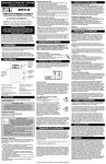
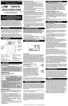
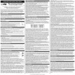
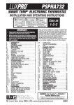
Complete, Easy To Read
INSTALLATION AND OPERATING INSTRUCTIONS
DHP2120
BATTERY POWERED, NON-PROGRAMMABLE
DIGITAL HEAT PUMP THERMOSTAT
REMOVING THE OLD THERMOSTAT:
1. Switch OFF the electricity to the heating/cooling equipment; then
proceed with the following:
2. Remove the front cover from your old thermostat. Most will
simply pull straight off, while others may be fastened by screws.
3. Take note of the letters printed near each of the wire terminals.
Attach adhesive labels (enclosed) to each wire for identification by
their terminal letter, not the color of the wire.
4. Make sure the wires do not fall back inside the wall. Remove and
label each wire one at a time, and do not allow the wires to touch
each other or any parts of the thermostat.
5. Loosen all screws on the old thermostat base, and remove it from
the wall.
52068
LUX PRODUCTS CORPORATION
Mt. Laurel, New Jersey 08054, USA
WARNING: Use Energizer ® or DURACELL ® Alkaline Batteries Only.
Energizer ® is a registered trademark of Eveready Battery Company, Inc.
DURACELL ® is a registered trademark of The Gillette Company, Inc.
I M P O R TA N T !
Please read all instructions carefully before beginning installation
and save for future reference. Before removing any wiring from
your existing thermostat, the wires must be labeled with their
terminal designations. Ignore the color of the wires since they
may not comply with any standard.
Thank you for your confidence in our product. You should become
fully acquainted with this thermostat before installing it for usage.
Follow the installation procedures carefully, and one step at a time.
This will save you time and minimize the chance of damaging either
the thermostat or the systems that it controls. These instructions
may contain information beyond that required for your particular
installation. Please save these instructions for future reference.
COMPATIBILITY
MOUNTING THE NEW THERMOSTAT:
1. Strip insulation leaving approximately 3/8 in. (10mm) of bare wire
on the ends, and clean off any corrosion present.
2. Fill the wall opening with non-combustible insulation to prevent
drafts from affecting the thermostat while in use.
3. Pull your new thermostat apart by applying pressure to the thumb
tab on the bottom edge of the unit, while pulling the front and
back halves apart from the bottom edge of the thermostat.
NOTE: If you are mounting the base to a soft material like
plasterboard, or if you are using the old mounting holes, the
screws may not hold. Drill a 3/16-in (4.8mm) hole at each
screw location, and insert the plastic anchors provided.
4. Route the wires through the large hole adjacent to the terminal
block, and hold the base plate against the wall. Position the base
for best appearance, and to hide any marks from an old
thermostat. Attach the base to the wall with the two screws
provided.
WIRING INFORMATION
• The DHP2120 thermostat can be used with most 24 volt: singlestage heat pumps, and 2 heat / 1 cool heat pump systems.
** Complete heating or cooling system wiring can be found in the
WIRE IDENTIFICATION AND WIRING SCHEMATICS section of this
instruction sheet. The schematics show system components for
brand new installations or for un-referenced wires.
• This thermostat cannot be used to control: conventional heating
and cooling systems, 3-wire zone valves, or 120/240 volt (line
voltage) heating or cooling systems. Ask your dealer for other
LUX ® thermostats to control those systems.
CONNECTING THE WIRES:
FEATURES
72
Quick & Easy
Temperature
Change
Buttons
˚
Large Easy to
Read Backlit
Display
FAN
Fan
Slide
Switch
SETUP OPTIONS
If batteries are presently installed, remove them from the thermostat
before proceeding with changing any of the options listed below. A
table similar to this one shown here is printed on the thermostat's
circuit board.
EMER
HEAT
OFF
COOL
Mode
Slide
Switch
• Digital, Non-Programmable
• Easy To Install
• Battery Powered Only
• F / C Selectable Temperature Display
• Set Temperature Range 45°F to 90°F
• Fixed 5 Minute Minimum Run /
Off Time For Compressor Protection
• Clean, Attractive Design
• Large, Easy To Read Display with
LED Backlight
• Adjustable Temperature Stops
INSTALLATION
PLEASE READ ALL INSTRUCTIONS CAREFULLY BEFORE BEGINNING
INSTALLATION.
CAUTION:
This thermostat is protected against normal static electric
discharges. However, in extremely dry weather you should
touch a grounded metal object before touching the thermostat
to minimize the risk of causing damage to the unit.
TOOLS REQUIRED:
• #1 Phillips screwdriver (small - medium)
• Drill with 3/16-in. (4.8mm) drill bit
• Wire stripper/cutter
CAUTION:
Turn off electricity to the appliance before
installing or servicing the thermostat or any part
of the system. Do not turn the electricity back
on until the work is completed.
• Your thermostat is a precision instrument. Please handle it with
care.
• Do not short (jumper) across the electric terminals on your
heating or cooling equipment to test the system. This may
damage the thermostat and void your warranty.
• All wiring must conform to all applicable local codes and
ordinances.
• This thermostat is limited to a maximum of 1.5 amps, total
current; higher current may cause damage to the thermostat .
THERMOSTAT LOCATION:
On replacement installations, mount the new thermostat in place of
the old one unless the conditions listed below suggest otherwise.
On new installations, follow the guidelines listed below.
1. Locate the thermostat on an inside wall, at about 5 ft. (1.5m)
above the floor, and in a room that is used often.
2. Do not install it where there are unusual heating conditions, such
as: direct sunlight, near a lamp, television, radiator, register,
fireplace, on a wall opposite a stove, or that carries hot water
pipes.
3. Do not locate in unusual cooling conditions, such as: on a wall
separating an unheated room, or in a draft from a stairwell, door,
or window.
4. Do not locate where air circulation is poor, such as: in a corner or
alcove, or behind an open door.
5. Do not locate in a damp area. This can lead to corrosion that may
shorten thermostat life.
6. Do not install the unit until all construction work and painting has
been completed.
JP1 (SCALE)
JP2 (B / O)
UP
DOWN
F
B
C
O
JP2 - [B] OR [O] TERMINAL USAGE OPTION:
This setting determines how the thermostat will use
the shared B/O terminal connection on the back
plate. Select the “B” option to have the B/O
terminal powered while in heat mode, and unpowered while in cool and off modes. Select the
“O” position to have the B/O terminal powered while
in cool mode, and un-powered while in heat and off
modes. If you are not sure which way to set this
option, consult the manufacturer of your heat pump
unit.
FAN MODE SWITCH:
The FAN switch has 2 positions: AUTO and ON. In the AUTO
position, the operation of the blower fan is determined only by the
on/off cycling of the heating and cooling system. In the ON position,
the system's blower fan will be commanded ON continuously at all
times, even when the system mode switch is in the OFF position.
PUSH BUTTONS:
There are two push buttons to the right of the unit's display screen.
These are used to adjust the set point temperature.
OPERATING INSTRUCTIONS
TEMPERATURE ADJUSTMENT:
While in HEAT, COOL, or EMER modes, a single press on either the
UP or DOWN button causes the word “SET” to appear on the screen,
and the set temperature value on the screen to start flashing. When
flashing, the set temperature can be altered by pressing either the
UP or DOWN button once per degree of change, or by holding either
button for at least two seconds to automatically increment the set
temperature quickly in the associated direction.
Based upon the relationship of the set temperature to the displayed
ambient room temperature, the thermostat will engage the first stage
of either heating or cooling, if a temperature demand is present.
If there is a large thermal demand present which is greater than the
first stage of heating can accommodate, then a second stage of
heating (W2) will be activated, showing the word “AUX” on the
display screen. There is approximately a 4-minute delay that is
imposed between the activation of the first stage of heating, and the
second stage of heating.
MINIMUM RUN/OFF TIME:
This is determined by the thermostat, and controls the minimum
length of time that the thermostat must remain with Heat or Cool
either On or Off, before it will automatically switch to the alternate
On or Off state. This feature prevents rapid or short cycling, and
also provides compressor protection. The duration of this delay is
fixed at 5 minutes between on or off load changes.
ADJUSTABLE TEMPERATURE STOPS:
There are two independent set temperature stops: a maximum heat
set temperature, and a minimum cool set temperature. Each of these
temperature stops is user adjustable in one-degree increments. The
heat temperature stop prevents the set temperature from being
adjusted higher than the heat temperature stop value. The cool
temperature stop prevents the set temperature from being adjusted
lower than the cool temperature stop value.
JUMPER SETTINGS:
There are 2 option jumpers located inside the thermostat on the
circuit board. These settings can be changed from their default
values by removing its corresponding black shorting cap and
installing the cap so that it is positioned on the adjacent pair of
metal pins. A change to either of the option jumpers will not be
recognized unless the thermostat has been without battery power for
at least 2 minutes, and then power is restored again. Each of these
jumpers changes a different setup option. The choices for these
options are listed in a table printed on the circuit board, and are also
printed adjacent to each individual setting jumper.
JP1 - FAHRENHEIT OR CELSIUS DISPLAY FORMAT:
This setting controls whether the temperature is
shown in degrees °F or °C on the LCD display
screen.
SYSTEM MODE SWITCH:
The MODE switch has 4 positions: EMER, HEAT, OFF, and COOL. In
the summer, set the switch to COOL to control cooling. In the
winter, set the mode switch to HEAT to control heating; set the mode
switch to EMER to control auxiliary heating only (if equipped). In
the EMER position, the heat pump compressor is disabled. When set
to OFF mode, the heating and cooling system will remain off.
DISPLAY ILLUMINATION:
Pressing either set temperature button will illuminate the display.
The light will remain on for approximately 12 seconds. While the
light is illuminated, pressing any of the 2 push buttons will cause the
light to remain on for approximately 12 more seconds.
5. Clean bare wire ends must be inserted in between the
black clamp and the brass terminal as shown here.
6. Securely tighten all electrical terminal screws
(even unused ones).
AUTO
ON
FRONT PANEL ITEMS
F
JP1
C
B
JP2
O
Once all optional jumper settings have been performed as described
in the previous section, ensure that the thermostat has been without
battery power for at least 2 minutes for the change to be recognized.
Now install new batteries into the thermostat. When installing
batteries, use two new Energizer ® or DURACELL ® “AA” size alkaline
batteries only. Ensure that the batteries are installed in the proper
direction as per the markings shown in the battery tray.
COMPLETING THE INSTALLATION
Install your new thermostat onto its base. To do this, start with the
bottom tilted out towards you at first, and line up the two holes in
the top of the thermostat with the two hooks on the top of the back
plate. Slowly pivot the bottom of the thermostat towards the back
plate and push firmly on the bottom half of the thermostat until it is
securely latched to the back plate. If the two thermostat halves do
not mate together easily, remove and try again. Do not attempt to
force them together if they do not appear aligned properly.
NOTE: Before use, remove the plastic film (if present) that is
protecting the LCD display screen.
Turn the electrical power back ON to both your heating and/or
cooling systems. Verify that both systems are operating properly.
When set to a high temperature, the heating system should provide
warm air after a short time in Heat Mode. Likewise, the cooling
system should provide cool air after a short time when set to a low
temperature in Cool Mode. Usually, sound from the heater and/or
cooling system units can be heard while either is running. Your
installation is now complete.
© 2 0 0 8 L U X P R O D U C T S C O R P O R AT I O N . A L L R I G H T S R E S E R V E D
To set the heat and cool temperature stops, place the system mode
switch in the OFF position. Press and hold the UP key while sliding
the mode switch from either OFF to HEAT (to adjust the maximum
heat set temperature), or from OFF to COOL (to adjust the minimum
cool set temperature). “Ht Lim” or “Cl Lim” will be displayed on the
LCD screen while you are setting the heat or cool limits respectively.
While in the adjustment mode for each of the temperature stops, use
the UP and DOWN buttons to adjust the limit value, just as you
would for adjusting the set temperature under normal operation.
NOTE: If no buttons are pressed for 4 seconds, the thermostat will
accept the limit value that was on the screen, and return to normal
operating mode, for the current mode switch position. Once,
complete, you should return to the adjustment mode again for both
heat and cool to confirm your desired settings for both temperature
modes have been accepted.
BATTERIES AND MAINTENANCE
The batteries in the thermostat should be replaced AT LEAST once
per year, or sooner if the “LO BAT” battery symbol appears in the
lower right portion of the display screen.
To replace the batteries in the thermostat, remove the thermostat’s
body from the wiring base plate attached to the wall by pressing the
thumb latch at the bottom center of the unit and swinging the front
body out towards you, up and away from the base. Remove the used
batteries from the battery tray and discard appropriately.
Install two new Energizer ® or DURACELL ®, “AA” size Alkaline
batteries into the battery tray. Observe the polarity markings shown
in the battery compartment to ensure proper installation. When
finished, hang the top of the unit by the tabs at the top corners of
the base, and then snap the bottom of the unit into place. Do not
use unnecessary force. If the body does not snap into place easily,
remove the body, re-hang it from the tabs at the top and try again.
TECHNICAL ASSISTANCE
If you have any problems installing or using this thermostat, please
carefully and thoroughly review the instruction manual. If you
require assistance, please contact our Technical Assistance
Department at 856-234-8803 during regular business hours between
8:00AM and 4:30PM Eastern Standard Time, Monday through Friday.
You can also receive technical assistance online anytime day or night
at http://www.luxproducts.com. Our web site offers you answers to
the most common technical questions, and also permits you to email
your questions to our technical support staff at your convenience.
WARRANTY
Limited Warranty: If this unit fails because of defects in materials or
workmanship within three years of the date of original purchase, LUX
will, at its option, repair or replace it. This warranty does not cover
damage by accident, misuse, or failure to follow installation
instructions. Implied warranties are limited in duration to three
years from the date of original purchase. Some states do not allow
limitations on how long an implied warranty lasts, so the above
limitation may not apply to you. Please return malfunctioning or
defective units to the location from which the purchase was made,
along with proof of purchase. Please refer to "Technical
ASSISTANCE" before returning thermostat. Purchaser assumes all
risks and liability for incidental and consequential damage resulting
from installation and use of this unit. Some states do not allow the
exclusion of incidental or consequential damages, so the above
exclusion may not apply to you. This warranty gives you specific
legal rights and you may also have other rights which vary from
state to state. Applicable in the U.S.A. and Canada only.
HEAT PUMP TERMINAL CROSS REFERENCE CHART
(DHP2120) ENGLISH - WIRE IDENTIFICATION AND WIRING SCHEMATICS
TABLEAU DE RÉFÉRENCE CROISÉE DE BORNE DE POMPE À CHALEUR
TABLA DE REFERENCIA PARA LA TERMINAL DE LA BOMBA DE CALEFACCIÓN
HEAT PUMP BRAND
CORRESPONDING TERMINALS
TAPE OFF (NOT USED)
MARQUE DE POMPES
À CHALEUR
BORNES
CORRESPONDANTES
RUBAN RETIRÉ
(NON UTILISÉ)
MARCA DE LA BOMBA
DE CALEFACCIÓN
TERMINALES
CORRESPONDIENTES
DESPRENDIMIENTO
(NO UTILIZADO)
E
G
Y
R
ARCO / Friedrich
X2
G
Y
RC
ARCO / Snyder General
E
G
Y
R
BARD
E
G
Y1
R
W2
BARD, HP, WH, MHP, HPQ
E
G
Y
R
W2
BDP / BRYANT
E
G
Y
R
O
CARRIER
E
G
Y
R
O
CARRIER 5Q
CARRIER 50Q, QT382
GE BAY
JANITROL / Goodman
B
C
L
C
X
B
X
L
W1
X
L
W1
C
F
Y1
C
L
W1
R
O
Y
RED
V
G
Y
R
G
Y
R
G
G
E
W2
Y
E
LENOX TYPICAL HP6
C
W2
Y, W1
X2
B
O
G
HEIL-QUAKER / Whirlpool
O
W2
R
to W2
COLEMAN
O
L
W2
C
L
W2
BLACK
O
W
B
O
W
B
Y
R
O
W2
C
F
M
V/VR
R
Y
X
E
F
M
V/VR
R
Y
X
E
F
M
V/VR
R
Y
X
L
LENOX HP16, 18, 19
E
F
M
V/VR
R
Y
X
L
MAGIC CHEF PE
E
G
Y
R
O
RHEEM / RUUD
E
G
Y
R
G
Y
R
O
W1
C
G
Y
R
O
W
B
SNYDER GENERAL H-R811
TRANE
X2
X
G
W1
R
Y1
E
C
G
W1
R
Y1
W2
C
WESCO / ADDISON
E
G
W1
R
O
WESTINGHOUSE H50
E
G
Y
R
O
F
C
V/VR
G
Y
R
O
W2
C/X1
L
G
Y
R
O
W
B
X
WHITE RODGERS
YORK
E
BLOWER
FAN
SYSTEM
XFMR
W
X
Z
System
Common
-
+
REVERSING
VALVE
HEAT
PUMP
AUX.
HEAT
N° 1
LES POMPES À CHALEUR À UN ÉTAGE TYPIQUES DE 24 VOLTS
ET LES SYSTÈMES DE POMPE À CHALEUR À 2 ÉTAGES DE CHALEUR /
1 ÉTAGE DE REFROIDISSEMENT SANS FIL DE CHAUFFAGE D'URGENCE
EMERGENCY
HEAT
BLOWER
FAN
SYSTEM
XFMR
REVERSING
VALVE
AUX.
HEAT
G
N° 2
LES SYSTÈMES DE POMPES À CHALEUR À
UN ÉTAGE DE REFROIDISSEMENT / 2 ÉTAGES DE CHAUFFAGE
TYPIQUES DE 24 VOLTS AVEC UN FIL DE CHAUFFAGE D'URGENCE
Y1 E
R B/O Y2 W2 C
G
R B/O Y2 W2 C
T
** Reportez-vous à la note
de câblage numéro 1
X
H2
R B/O Y2 W2 C
-
+
HEAT
PUMP
Y1 E
F
E
WESTINGHOUSE HE
G
System
Common
L
WESCO
WEATHERKING
Y1 E
R B/O Y2 W2 C
**Refer To
Wiring Note #1
C
B
G
(DHP2120) FRENCH - SCHÉMAS D'IDENTIFICATION DES FILS ET DU CÂBLAGE
LENOX HP9, 10
W
Y1 E
TYPICAL 24 VOLT, 2-STAGE HEAT / 1-STAGE COOL
HEAT PUMP SYSTEMS
WITH EMERGENCY HEAT WIRE PRESENT
T
LENOX HP8
W2
#2
TYPICAL 24 VOLT, SINGLE-STAGE HEAT PUMPS AND
2-STAGE HEAT / 1-STAGE COOL HEAT PUMP SYSTEMS
WITH NO EMERGENCY HEAT WIRE
L
C
G
#1
L1
Système
commun
X
+
POMPE À
CHALEUR
WIRING DIAGRAM NOTES:
1. The DASHED lines in wiring diagram #1 are optional depending upon your system type. Single stage heat pumps will not have wires
present for the “E” or “W2” terminals. For a 2-Heat / 1-Cool system with NO Emergency heat wire, AUX heat will be connected to
“W2”. A jumper wire may be placed in between the “E” and “W2” terminals to allow Emergency Heat Mode.
2. For Heat Pumps, use either the “B” or “O” wire, NOT BOTH.
3. If “Y” and “C” wires are both present, then “C” is a common wire. Do not connect this “C” wire to your thermostat.
4. If you have a “B” wire in your system that is used as a common wire, connecting it to the “B/O” terminal on this thermostat may
damage your system and/or the thermostat.
NOTES DU DIAGRAMME DE CÂBLAGE :
1. Les lignes en TRAITS TIRÉS du diagramme de câblage 1 sont optionnelles et leur utilisation dépend de votre type de système. Les
pompes à chaleur à un étage n'ont pas de fils pour les bornes « E » ou « W2. » Pour un système à 2 chauffage / 1 refroidissement
SANS fil de chauffage d'urgence, la chaleur AUX sera branchée à « W2 ». Un fil de calier peut être placé entre les bornes « E » et
« W2 » pour permettre l'utilisation du mode de chau ffage d'urgence.
2. Pour les pompes à chaleur, utilisez soit le fil « B » ou « O », NON PAS LES DEUX.
3. Si vous avez les fils « Y » et « C », alors le « C » est le fil commun du système. Ne branchez pas ce fil « C » à votre thermostat.
4. Si vous avez un fil « B » dans votre système et si ce fil est utilisé comme fil commun, le brancher à la borne « B/O » du thermostat
pourrait endommager votre système et/ou le thermostat.
NOTAS DEL DIAGRAMA DEL CABLEADO:
1. Las líneas PUNTEADAS en el diagrama del cableado #1 son opcionales, dependiendo del tipo de sistema. Las bombas de
calefacción de una fase no contienen cables para las terminales “E” ni “W2”. Para un sistema de 2 fases de calefacción y una de
enfriamiento, NO se conecta el cable de calefacción de emergencia ni el auxiliar (AUX) en la terminal “W2”. Puede colocar un
cable para formar un puente entre las terminales “E” y “W2” y permitir un modo de calefacción de emergencia.
2. Para las bombas de calefacción, utilice el cable “B” o el cable “O”, NUNCA USE AMBOS.
3. Si tanto el cable “Y” como el “C” están presentes, entonces es más probable que el “C” sea el cable común del sistema. No
conecte el cable “C” a su termostato.
4. Si en su sistema hay un cable “B” que se utiliza como cable común, no lo conecte a la terminal “B” ni “O” del termostato, pues
podría dañar tanto su aparato como su sistema.
VENTILATEUR
SOUFFLANT
Système
commun
-
SYSTÈME
XFMR
+
ROBINET
INVERSEUR
POMPE À
CHALEUR
AUX.
CHALEUR
CHAUFFAGE
D'URGENCE
VENTILATEUR
SOUFFLANT
-
SYSTÈME
XFMR
ROBINET
INVERSEUR
AUX.
CHALEUR
(DHP2120) - IDENTIFICACIÓN DE CABLES Y DIAGRAMAS DE CABLEADO
#1
#2
BOMBAS TÍPICAS DE CALEFACCIÓN DE UNA FASE Y SISTEMAS
TÍPICOS CON BOMBA DE CALEFACCIÓN DE 2 FASES
Y AIRE ACONDICIONADO DE 1 FASE, TODOS DE 24 VOLTIOS
Y1 E
G
SISTEMAS TÍPICOS CON BOMBA DE CALEFACCIÓN DE 2 FASES
Y AIRE ACONDICIONADO DE 1 FASE DE 24 VOLTIOS,
CON CABLE DE CALEFACCIÓN DE EMERGENCIA
Y1 E
R B/O Y2 W2 C
G
R B/O Y2 W2 C
**Consulte la Nota
de cableado #1
Sistema
Común
Sistema
Común
-
+
BOMBA DE
CALEFACCIÓN
VENTILADOR
SISTEMA
XFMR
+
VÁLVULA DE
INVERSIÓN
CALEFACCIÓN
AUX.
BOMBA DE
CALEFACCIÓN
CALEFACCIÓN DE
EMERGENCIA
VENTILADOR
-
SISTEMA
XFMR
VÁLVULA
DE INVERSIÓN
CALEFACCIÓN
AUX.