1
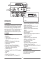
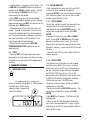
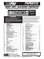
PSPHA732
SMART TEMP® ELECTRONIC THERMOSTAT
INSTALLATION AND OPERATING INSTRUCTIONS
PM
SET
SUNDAY
HEAT
OFF
WEEKDAY
PROGRAM
COOL
SET
DAY/TIME
Installs Easily
Set Day & Time
Choose Heat or Cool
IMPORTANT!
• Please read all instructions carefully before beginning
installation. Save them for future reference.
• Before removing any wiring from your existing thermostat,
its wires must be labeled with their terminal designations.
• Ignore the color of the wires since they may not comply
with any standard.
1.
2.
3.
4.
4.1.
4.2.
4.3.
4.4.
4.5.
4.5.1.
4.5.2.
4.5.3.
5.
5.1.
5.2.
5.3.
5.4.
5.5.
5.6.
5.7.
5.8.
5.9.
5.10.
5.11.
5.12.
5.12.1.
5.12.2.
5.12.3.
5.13.
5.14.
6.
6.1.
6.2.
6.2.1.
6.2.2.
COMPATIBILITY . . . . . . . . . . . . . . . . . . . . . . . .
FEATURES. . . . . . . . . . . . . . . . . . . . . . . . . . . . .
ELECTRICAL RATINGS . . . . . . . . . . . . . . . . . . . .
INSTALLATION . . . . . . . . . . . . . . . . . . . . . . . . . .
TOOLS REQUIRED . . . . . . . . . . . . . . . . . . . . .
LOCATION. . . . . . . . . . . . . . . . . . . . . . . . . . . .
REMOVAL OF OLD UNIT. . . . . . . . . . . . . . . . .
MOUNTING . . . . . . . . . . . . . . . . . . . . . . . . . . .
WIRING. . . . . . . . . . . . . . . . . . . . . . . . . . . . . .
TERMINAL DESCRIPTIONS . . . . . . . . . . . . . .
CONNECTING THE WIRES . . . . . . . . . . . . . . .
COMPLETING YOUR INSTALLATION . . . . . . .
OPERATING BASICS . . . . . . . . . . . . . . . . . . .
UP/DOWN CHANGE KEYS. . . . . . . . . . . . . . . .
SET DAY AND TIME . . . . . . . . . . . . . . . . . . . .
TEMPERATURE CONTROL MODES. . . . . . . . .
EMERGENCY (EMER) . . . . . . . . . . . . . . . . . . .
AUTOCHANGE (AUTO) . . . . . . . . . . . . . . . . . .
HEAT . . . . . . . . . . . . . . . . . . . . . . . . . . . . . . . .
COOL. . . . . . . . . . . . . . . . . . . . . . . . . . . . . . . .
OFF . . . . . . . . . . . . . . . . . . . . . . . . . . . . . . . . .
DEFAULT PROGRAM . . . . . . . . . . . . . . . . . . .
HOLD . . . . . . . . . . . . . . . . . . . . . . . . . . . . . . .
OVERRIDE. . . . . . . . . . . . . . . . . . . . . . . . . . . .
FAN MODES . . . . . . . . . . . . . . . . . . . . . . . . . .
AUTO. . . . . . . . . . . . . . . . . . . . . . . . . . . . . . . .
ON. . . . . . . . . . . . . . . . . . . . . . . . . . . . . . . . . .
CLEAN CYCLE® . . . . . . . . . . . . . . . . . . . . . . . .
DISPLAY ILLUMINATION . . . . . . . . . . . . . . . .
AUDIBLE BEEP . . . . . . . . . . . . . . . . . . . . . . . .
PROGRAMMING . . . . . . . . . . . . . . . . . . . . . .
DEFAULT TEMPERATURE PROGRAM . . . . . . .
EDITING HEAT OR COOL PROGRAMS . . . . . .
WEEKDAY PROGRAMMING . . . . . . . . . . . . . .
WEEKEND PROGRAMMING . . . . . . . . . . . . . .
2
2
2
3
3
3
3
3
4
4
4
4
5
5
5
5
5
5
5
6
6
6
6
6
6
6
6
7
7
7
7
7
7
7
8
Easy as
1–2–3
Thank you for your confidence in our product. To obtain the best
results from your investment, please read these instructions and
acquaint yourself with your purchase before installing your new
thermostat. Then follow the installation procedures, one step at a
time. This will save you time and minimize the chance of
damaging the thermostat and the systems it controls.
These instructions may contain information beyond that required
for your particular installation. Please save for future reference.
6.3.
6.4.
7.
7.1.
7.2
7.2.1.
7.2.2.
7.3.
7.4.
7.5.
7.5.1.
7.5.2.
7.6.
7.6.1.
7.6.2.
7.7.
8.
8.1.
8.2.
8.3.
8.4.
8.5.
8.6.
9.
9.1.
10.
11.
12.
13.
14.
15.
CLEAN CYCLE®
(IAQ FAN PROGRAMMING) . . . . . . . . . . . . . . 8
COPY. . . . . . . . . . . . . . . . . . . . . . . . . . . . . . . . 9
ADVANCED FEATURES . . . . . . . . . . . . . . . . . 9
KEYBOARD LOCK . . . . . . . . . . . . . . . . . . . . . . 9
FILTER MONITOR . . . . . . . . . . . . . . . . . . . . . . 9
FILTER USAGE . . . . . . . . . . . . . . . . . . . . . . . . 9
FILTER LIMIT . . . . . . . . . . . . . . . . . . . . . . . . . 9
ENERGY USAGE . . . . . . . . . . . . . . . . . . . . . . . 10
CALIBRATION OFFSET . . . . . . . . . . . . . . . . . . 10
RESET. . . . . . . . . . . . . . . . . . . . . . . . . . . . . . . 10
HARDWARE RESET . . . . . . . . . . . . . . . . . . . . 10
SOFTWARE RESET . . . . . . . . . . . . . . . . . . . . . 10
TEMPERATURE VARIATION / SWING . . . . . . . 10
SWING 1 – 1st STAGE . . . . . . . . . . . . . . . . . . 11
SWING 2 – 2nd STAGE . . . . . . . . . . . . . . . . . . 11
DEAD BAND . . . . . . . . . . . . . . . . . . . . . . . . . . 11
SET UP OPTIONS. . . . . . . . . . . . . . . . . . . . . . 11
MINIMUM RUN TIME – J3 . . . . . . . . . . . . . . . 12
CLOCK FORMAT – J4 . . . . . . . . . . . . . . . . . . . 12
TEMPERATURE DISPLAY FORMAT
(F/C DISPLAY) – J5. . . . . . . . . . . . . . . . . . . . . 12
SMART RECOVERY – J6. . . . . . . . . . . . . . . . . 12
FAN OVERRUN TIME – J7. . . . . . . . . . . . . . . . 12
REPOSITIONING JUMPERS . . . . . . . . . . . . . . 12
BATTERIES/MAINTENANCE . . . . . . . . . . . . . 12
BATTERY INSTALLATION . . . . . . . . . . . . . . . . 13
TECHNICAL ASSISTANCE . . . . . . . . . . . . . . . 13
WARRANTY . . . . . . . . . . . . . . . . . . . . . . . . . . 13
WIRING DIAGRAMS. . . . . . . . . . . . . . . . . . . . 14
CROSS REFERENCE CHART . . . . . . . . . . . . . 15
USER PROGRAM TABLE . . . . . . . . . . . . . . . . 16
JUMPER TABLE. . . . . . . . . . . . . . . . . . . . . . . 16
WARNING: Use Energizer® or DURACELL®
Alkaline Batteries Only.
Energizer® is a registered trademark of Eveready Battery Company, Inc.
DURACELL® is a registered trademark of The Gillette Company, Inc.
Mt. Laurel, New Jersey 08054, USA ● www.luxproproducts.com
52091
TU
EASY
PROGRAMMING
WITH
LUX SPEED DIAL®
UP
DOWN
5:36 72
LARGE
BACKLIT
DISPLAY
LIGHT
IAQ
INDEPENDENTLY
PROGRAMMABLE
FAN
MODE SWITCH
PSPHA732
TU
5:36 72
PSPHA732
1. COMPATIBILITY
• Programmable Filter Monitor and Indicator
• Energy Usage Monitor
• Battery Free Nonvolatile Memory For All
Programs And Settings
• Battery or System Powered with Battery
Backup
• Batteries Included (2 AA)
• Auto-Changeover
• Programmable Auto-Changeover Dead band
(1˚ to 6˚ F) (1˚ to 3˚ C)
• Keyboard Lockout
• Temperature Offset (User Calibration)
• On Screen Low Battery Indicator
• F/C Temperature Display
• 12/24 Hour Clock
• 2 or 5 Minute Short Cycle Protection
• 1 Minute Optional Residual Fan
• Multi-Stage Adjustable Temperature Differential
/ Cycle Rate
• Terminals: E, C, Y1, R, Y2, W, B, O, G
Your PSPHA732 is compatible with Heat Pumps
Up to 3 Stages of Heat and 2 Stages of Cooling.
This includes Auxiliary and Emergency Heat. It
cannot be used with 120 volt heating systems or
3 wire zone valves. Ask your dealer for other
LUXPRO thermostats to control those systems.
2. FEATURES
•
•
•
•
•
•
•
•
•
•
•
•
•
•
Heating and Cooling
Electronic
Programmable
7 Day Programming (Each day can be
different)
Auxiliary and Emergency Heat Indicators
Programming Copy Button
Large Display
Electro-luminescent Display Backlight
Clean Cycle® (Patent No. 6,988,671) IAQ
Independently Programmable Fan
4 Periods Per Day
Temporary Override 1-4hr (CAT24 Residential
Compliant)
Hold
Optional Smart Recovery
Easy Programming with LUX Speed Dial®
3. ELECTRICAL RATINGS
• 30V maximum (24VAC nominal)
• 1.5A maximum per terminal
• 2.0A terminal sum
2
C A U T I O N:
Your thermostat is protected against normal
static electric discharges. To minimize the
risk of damaging the unit in extremely dry
weather, touch a grounded metal object before
touching your thermostat.
W A R N I N G:
• Read instructions carefully before removing
any wiring from an existing thermostat.
• Label wires before they are removed.
• When removing wires from their terminals,
ignore the color of the wires since they may
not comply with any standard.
4. INSTALLATION
4.3 REMOVAL OF OLD UNIT
1. Switch electricity to the furnace and air
conditioner OFF; then proceed with the following
steps.
2. Remove cover from old thermostat. Most are
snap-on types and simply pull off. Some have
locking screws on the side. These must be
loosened.
3. Note the letters printed near the terminals.
Attach labels (enclosed) to each wire to
identification. Label and remove wires one at a
time. Make sure the wires do not fall back inside
the wall.
4. Loosen all screws on the old thermostat and
remove it from the wall.
4.1 TOOLS REQUIRED
• #1 Phillips screwdriver (small)
• Drill with 3/16-in. (4.8mm) bit
• Wire stripper/cutter
4.2 LOCATION
• On replacement installations, mount the new
thermostat in place of the old one, unless the
conditions listed below suggest otherwise. On
new installations, follow the guidelines listed
below.
• Locate the thermostat on an inside wall, about 5
ft. (1.5m) above the floor, in a room that is used
often.
• Do not locate where air circulation is poor, such
as in a corner or an alcove; or behind an open
door.
• Do not install it where there are unusual heating
conditions, such as: in direct sunlight; near a
lamp, television, radiator, register, or fireplace;
near hot water pipes in a wall; near a stove on
the other side of the wall.
• Do not locate in unusual cooling conditions,
such as: on a wall separating an unheated room;
or in a draft from a stairwell, door, or window.
• Do not locate in a damp area. This can lead to
corrosion that will shorten thermostat life.
• Do not install the unit until all construction work
and painting has been completed.
4.4 MOUNTING
5. Strip insulation 3/8 in. (9.5mm) from wire
ends and clean off any corrosion.
6. Fill wall opening with non-combustible
insulation to prevent drafts from affecting the
thermostat.
7. With each thumb on a release tab at the
bottom of the body, and fingers over the top of
the unit, release the unit from its base plate by
squeezing the tabs into the body.
8. Separate the unit from its base plate by pulling
the body outward at its bottom.
3
C A U T I O N:
• Be careful not to drop the unit or disturb
electronic parts.
• Leave the door closed while the body is
being removed from the base.
Y2: Active while calling for a 2nd stage of
heating/cooling.
R: Transformer, Provides Power
Y1: Active while calling for a 1st Stage of
heating/cooling.
C: Use of this terminal allows the unit to be
system powered rather than battery powered.
E: This terminal is active when the thermostat is
calling for Emergency Heat.
9. Route the wires through the open areas in the
base plate above the terminals. Hold the base
against the wall, with the wires coming through.
Position the base for the best appearance (to
hide any marks from an old thermostat). Attach
the base to the wall with the two screws
provided.
4.5.2 CONNECTING THE WIRES
10. Loosen wire clamp screws
just enough to slide wire under
the black top part of the clamp.
11. Connect stripped wire ends,
by trapping it between its black clamp and brass
terminal. Then tighten its terminal screw.
12. Tape the ends of any unused wires.
N O T E: If you are mounting the base to a
soft material like plasterboard or if you are
using the old mounting holes, the screws may
not hold. Drill a 3/16-in. (4.8mm) hole at
each screw location, and insert the plastic
anchors provided. Then mount the base as
described below.
4.5.3 COMPLETING YOUR INSTALLATION
13. Install two new Energizer® or DURACELL®
"AA" size alkaline batteries at this time. For
instructions, refer to BATTERIES/MAINTENANCE.
14. Configure your thermostat at this time. Refer
to SETUP OPTIONS.
15. Install your thermostat on its base. To do
this, hang the top of the unit by the tabs on the
base, then snap the bottom of the unit into place.
Do not use unnecessary force. If the body does
not snap into place easily, remove the body, rehang it from tabs and try again.
16. Turn the power back on to your heating
and/or air conditioning system.
17. Verify that the system and its fan are
operating properly. When set to a high
temperature, the heating system should provide
warm air after a short time. Likewise, a cooling
system should provide cool air after a short time.
Usually sound from the furnace and air
conditioning units can be heard while they are
running. The rush of moving air should be heard
within a short time after either has been started.
4.5 WIRING
• Using the terminal descriptions below, wiring
diagram on page 14, and your labels, determine
the appropriate wiring for your system.
• Also Refer to the Heat Pump Cross-reference
Chart on page 15.
• If you are unsure or need assistance, call the
LUX Technical Assistance Dept. (see TECHNICAL
ASSISTANCE.)
4.5.1 TERMINAL DESCRIPTIONS
• See drawing on page 16 showing layout of
terminals.
G: The fan terminal is live at any time the
thermostat attempts to turn the system fan or
blower on.
O: Live at any time the unit is in Cool mode.
B: Live at any time unit is in Heat Mode.
W: Active while the thermostat is calling for
auxiliary 3rd stage of heat.
4
NOTE: If you have an electric system and the
blower does not operate after installation,
verify that the electric/gas option in installer
set up is set to Electric, see SETUP OPTIONS.
5.4 EMERGENCY (EMER)
• Use EMERGENCY position on slide switch to
active your emergency heating. You will see
"EMER HEAT" appear in the display. Press
temperature UP or DOWN keys until your
desired temperature is displayed in the HEAT SET
area of the display. "EMER HEAT" will flash if it
is activated and running.
• Putting your thermostat in this mode will
disable the other 2 stages of heating. (Your heat
pump will be disabled).
• The 3rd stage of heat will deenergize as soon as
the temperature setpoint is reached. The letters
"EMER" will disappear.
18. Your installation is now complete.
5. OPERATING BASICS
5.1 UP/DOWN CHANGE KEYS
• These are the two upper keys, just right of the
units display. They are used to adjust set
temperatures, and make other setting changes.
• Pressing these keys once will adjust a setting
one step in the associated direction.
• If there are many choices for a value, usually
that setting will advance while holding one of
these keys. Some settings though, must be
changed one press at a time.
5.5 AUTOCHANGE (AUTO)
• Use AUTOCHANGE mode to allow your
thermostat to switch between HEAT and COOL
modes automatically. Slide the mode switch to
AUTO and AUTO CHANGE will be displayed
above the set temperature. You can determine
whether your thermostat is in HEAT or COOL
mode by whether HEAT or COOL is visible in the
set temperature area of the units display. Initially
HEAT or COOL may not be active until a
determination is made that HEAT or COOL is
necessary.
• The programmed temperature for a given mode
will be used as the set temperature for that
mode.
• Pressing the UP/DOWN keys at the same time
will force the unit to change modes and make the
programmed set temperature the new set
temperature.
5.2 SET DAY AND TIME
To set the correct time after the unit has lost
power or after reset:
• Open the door on the front of the thermostat.
• Rotate the dial to SET DAY/TIME. The
abbreviation for the day of week will flash.
• Use the UP key to advance to the current day.
• Press NEXT to adjust the time. Time will flash.
• Use the UP/DOWN keys to set the time.
• Pressing NEXT again will toggle from Set Time
to Set Day, or vice versa.
• Return the dial to its RUN position.
5.3 TEMPERATURE CONTROL MODES
When a unit has first been powered up with the
dial in the RUN position, your thermostat will
begin to control your heating and/or air
conditioning system according to it’s default
program. There is a 5-position slide switch to
change temperature control modes. Slide the
switch to the mode you would like to use.
5.6 HEAT
• Use HEAT mode to control your furnace and
warm your home.
• In HEAT mode, HEAT is displayed right of the
set temperature.
• HEAT will display solid if there is no load.
• While the 1st stage of heating is active, HEAT
will flash.
5
• If a second stage of heat is called for, the
flashing rate of HEAT increases
• If the 3rd stage of heat activates, the display will
also flash "AUX " in addition to HEAT flashing.
5.11 OVERRIDE
During RUN, set temperatures may be
temporarily altered from their programmed
values. Immediately after a set temperature has
been altered, the 2-hour default duration may be
adjusted within the range from 1 to 4 hours. The
temporary set temperature(s) will be used for the
duration of the OVERRIDE.
• Press either the UP or DOWN key. The current
modes set temperature will begin to flash.
• Adjust the set temperature as desired.
• After a few seconds, the default 2-hour duration
will flash in the time area of the display.
• Adjust the duration in 15-minute increments,
from between 1 to 4 hours.
• When the duration stops flashing, the
OVERRIDE has been initiated and the Set
Temperature side of the display will show
OVERRIDE.
• The adjust temperature will remain the set
temperature in the current mode for the duration
of the OVERRIDE. Then temperature settings
return to their program values.
• OVERRIDE may be cancelled by initiating a
HOLD and then canceling it, changing the
position of the mode switch, or rotating the
SPEED DIAL®.
5.7 COOL
• Use COOL mode to control your air conditioner,
cooling your home.
• In COOL mode, COOL is displayed right of the
set temperature.
• COOL will display solid if there is no load.
• While the 1st stage of cooling is active, COOL
will flash.
• If a second stage of cooling is called for, the
flashing rate of COOL increases
5.8 OFF
• Slide the MODE switch to OFF when no heating
or cooling is desired. Heating and cooling will be
disabled, and the set temperature side of the
display will be empty.
5.9 DEFAULT PROGRAM
• As supplied from the factory, your thermostat
will use its default program for temperature
control. This program and all other settings may
be restored to their default values via a
SOFTWARE RESET. Please refer to DEFAULT
TEMPERATURE PROGRAM for program times
and temperatures.
5.12 FAN MODES
• The FAN switch controls which of three fan
modes your thermostat is to use. These modes
are AUTO, CLEAN and ON.
5.10 HOLD
Hold is the simplest method to maintain fixed set
temperatures.
• Press HOLD once to enter permanent
temperature HOLD while in RUN or OVERRIDE.
HOLD will be displayed above the set
temperature in the display.
• Pressing this button again will toggle HOLD off
and return to RUN and the programmed set
temperature.
• Changing system mode or rotating the SPEED
DIAL® will also cancel a HOLD.
5.12.1 AUTO
• AUTO mode runs the fan only to fulfill your
heating and cooling requirements.
5.12.2 ON
• ON mode runs your system fan continuously.
6
5.12.3 CLEAN CYCLE®
• LUX’s Clean Cycle® allows you to program a
forced air system to flow air through your
system’s filter, cleaning the air in your home,
even when heating or cooling is not being
utilized. In CLEAN mode the fan maintains the
programmed minimum run time; it may run
additional time as required to maintain
temperature control. The program used avoids
additional fan time when the minimum run time
has been met over the last hour through
temperature control. Minimum fan run times are
met by running one-third the hourly requirement
at twenty-minute intervals. The default minimum
fan run time is 15 minutes per hour.
PERIOD
Morning
Day
Evening
Night
HEAT MODE
COOL MODE
6:00 AM 700F (210C) 6:00 AM 780F (260C)
8:00 AM 620F (170C) 8:00 AM 850F (290C)
6:00 PM 700F (210C) 6:00 PM 780F (260C)
10:00 PM 620F (170C) 10:00 PM 820F (290C)
6.2 EDITING HEAT OR COOL PROGRAMS
You can change any preset times and/or
temperatures to suit your schedule for each day
of the week (7 Day Programming). The four
periods each day are named Morning (MORN),
Day, Evening (EVE), and Night (NITE).
6.2.1 WEEKDAY PROGRAMMING
To change the HEAT or COOL program:
• Set to HEAT, COOL, or AUTO with the mode
switch.
• Rotate dial to SET WEEKDAY PROGRAMS.
PROGRAM, Mo, MORN and START AT will be
displayed, with the Set Time flashing.
5.13 DISPLAY ILLUMINATION
For visibility in the dark, your LUX thermostat
incorporates an attractive electro-luminescent
display backlight.
• Press the light bulb button right of the display
to illuminate.
• Pressing this or other buttons will keep the
display illuminated.
Programming is performed in the following
order.
1 Mo Morn Start Time
2 Mo Morn Heat Set Temperature
3 Mo Morn Cool Set Temperature
4 Mo Day Start Time
5 Mo Day Heat Set Temperature
6 . . . and so on until Fri Nite is fully
programmed at which point pressing NEXT again
will begin the list at Mo Morn Start Time.
5.14 AUDIBLE BEEP
When a key is pressed, the thermostat will emit
an audible beep. The beep will terminate within 1⁄2
second while a button is held.
6. PROGRAMMING
• Use the UP/DOWN keys to change the start
time for this period. Press UP/DOWN buttons to
change the time in 15-minute increments. Hold
UP/DOWN button to change the time at rate of
60 minutes/second.
• One period ends at the start time of the next
period. The end of one period may not be any
closer to the beginning of the next period than
one 15-minute increment. Moving a start time
too close to the next start time results in the
latter time being pushed ahead too. Press NEXT
6.1 DEFAULT TEMPERATURE PROGRAM
As supplied from the factory, the following
program will be used for temperature control in
RUN MODE. This program and all other software
settings may be restored to their default values
via a SOFTWARE RESET.
7
to accept the displayed start time and advance to
the HEAT SET TEMPERATURE, it will flash to
show that it may be edited.
• The HEAT SET TEMPERATURE will be displayed
on the right side of the display with the HEAT
indicator visible.
• Edit the HEAT SET TEMPERATURE, then press
NEXT to accept and advance to the COOL SET
TEMPERATURE, it will flash to show that it may
be edited.
• There is a minimum value that be maintained
between the HEAT SET TEMPERATURE and
COOL SET TEMPERATURE. That value is called
the Dead band. Its default is 3˚F. It is
programmable and may be changed. See
ADVANCED FEATURES. If you move the heat set
temperature too close to the cool set
temperature, the cool set temperature will move
away from the heat set temperature to maintain
the Dead Band. Conversely, the heat set
temperature will move if you adjust the cool set
temperature too close.
• Edit the COOL SET TEMPERATURE, then press
NEXT to accept and advance to the next period.
• When you have changed the Cool set
temperature to your desired temperature, press
NEXT to advance to the next period. Its start
time will be flashing indicating that it is under
edit.
• When all the periods for a day have been set,
the start time for the next weekday Morning
period will be displayed to begin editing the
settings for that day.
• Complete programming for all weekdays and
rotate the dial back to RUN to accept all current
values and end the programming session.
6.3 CLEAN CYCLE® (IAQ FAN
PROGRAMMING)
Clean Cycle® programming is similar to
temperature programming. It has four
consecutive periods, which are independent of
the four temperature periods. The default setting
for your systems fans CLEAN CYCLE® program
requires it to run at least 15 minutes per hour.
Default Program periods are:
Default Periods
MORN
DAY
EVE
NIGHT
Time
6:00 AM (6:00)
8:00 AM (8:00)
6:00 PM (18:00)
10:00 PM (22:00)
To edit the CLEAN CYCLE® program:
• Move Fan switch to CLEAN.
• Rotate the dial to AIR FILTER.
• Press HOLD for 2 seconds.
• PROGRAM, FAN, START AT, MO (day) and
MORN (period) will all be visible. Current start
time will flash in time area.
Program is performed in the following order.
1 Mo Morn Start Time
2 Mo Morn Minimum ON Time
3 Mo Day Start Time
4 Mo Day Minimum ON Time
5 . . . and so on until Sun Night is fully
programmed at which point pressing NEXT again
will begin the list at Mo Morn Start Time.
• Press UP/DOWN to change start time for this
period in 15-minute increments. Hold UP/DOWN
button to change the time at rate of 60
minutes/second.
• Press NEXT to accept the start time, and
advance to set minimum fan on time per hour.
Current minimum fan run time will flash with
MIN/HR.
• Press UP/DOWN to alter the minimum ON Time
setting by 3 minutes. Time can be adjusted from
6.2.2 WEEKEND PROGRAMMING
Weekend programming is identical to weekday
programming except that you must rotate the dial
to SET WEEKEND PROGRAMS and the sequence
of days that you may program is Sa and Su, then
repeating this two day sequence.
8
0 to 60 minutes in increments of 3 minutes. Set
0 MIN/HR to allow AUTO control for particular
periods while CLEAN is used in others. Set the
fan duration to 60 MIN/HR to run the fan
continuously for this period.
• Press NEXT to advance to the next period.
After the four program periods of day have been
programmed, pressing NEXT will advance to the
following day’s MORN period.
• One period ends at the start time of the next
period. The end of one period may not be any
closer to the beginning of the next period than
one 15-minute increment. Moving a start time
too close to the next start time results in the
latter time being pushed ahead too.
• Rotate the dial away from the SET FAN
PROGRAMS/AIR FILTER position to exit fan
programming.
7.2 FILTER MONITOR
• Your thermostat will warn you that your HVAC
system’s air filter should be changed by
displaying FILTER in the time temperature display
area, after the system’s fan has run the number
of hours specified by this limit.
7.2.1 FILTER USAGE
To view the number of hours the thermostat has
activated the fan since the last timer reset:
• Rotate the dial to the AIR FILTER position. The
current filter usage will be shown with HRS
FILTER.
• To reset the timer to 0, press UP or DOWN
once. Pressing UP or DOWN again will toggle
between 0 and the current value. The value in
display when you exit this mode will be the value
retained in memory. Leave the value at 0 to reset
the timer.
• To exit the AIR FILTER mode, rotate the dial to
another position.
6.4 COPY
• Pressing COPY will copy the previous day’s
temperature or fan program into the current day
and advance the thermostat to the beginning of
next day.
7.2.2 FILTER LIMIT
This general rule will provide you with a good
estimate of your filter’s life in hours. Assume
that the fan will run at 1/3 duty cycle or 8 hours
per day. Common 90-day filters are then good
for 90*24/3=720 hours of use. This is the
default limit value. Setting the filter counter limit
to 0000 will disable the change filter indicator.
Valid entries are from 0 to 2000 hours.
To set the number of hours of filter use before
replacement is indicated:
• Rotate the dial to the AIR FILTER position. The
current filter usage will be shown with HRS
FILTER.
• Hold NEXT for 2 seconds. The Filter limit will
be displayed.
• Refer to your Air Filter package to determine
your filter’s recommended life. If given in days,
multiply by 8 to find the recommended setting in
hours of filter usage.
7. ADVANCED FEATURES
7.1 KEYBOARD LOCK
• To prevent tampering Press NEXT, NEXT, NEXT,
HOLD. This sequence of keys will lock and
unlock all settings and programs. When locked,
a padlock icon will be visible
above the time / temperature
area of the display.
9
• Use UP/DOWN keys to adjust the filter limit in
10-hour increments to the recommended value.
• Rotate the dial to RUN to finish this setting.
Temperature Offset value will flash.
• Use the UP/DOWN keys to adjust the offset
value.
• Return the dial to its RUN position to accept the
new value.
7.5 RESET
Your thermostat has two RESET buttons. The
Software RESET in on the front of the thermostat
behind the door. It is labeled RESET.
HARDWARE RESET is on the rear of the circuit
board.
7.3 ENERGY USAGE
Your thermostat records the total number of
hours the thermostat has activated heating and
cooling with six separate timers. They measure:
• Today’s cumulative heating time.
• Yesterday’s cumulative heating time.
• Total cumulative heating time.
• Today’s cumulative cooling time.
• Yesterday’s cumulative cooling time.
• Total cumulative cooling time.
7.5.1 HARDWARE RESET
Use this small white button labeled H_RST after
changing Setup Option Jumper positions to
effect the changes. The Hardware RESET turns
Heat, Air and Fan off, resets the unit’s clock, and
reads the Setup Option jumper positions, before
initiating normal operation.
To view HEAT and COOL energy usage:
• Slide the mode switch to HEAT or COOL.
• Rotate the dial to the ENERGY USAGE position,
to review today’s usage. HRS USAGE, Mode and
Current Day are all shown along with the usage
value.
• Press NEXT to review yesterday’s usage.
• Press NEXT again to review Total usage. The
Total timer may be changed to zero by pressing
UP or DOWN while Total time is displayed. To
restore count, press UP or DOWN again.
• To finish review and/or reset of this mode’s
energy monitor, rotate the dial to another mode.
The current values will be the values retained in
memory. Leave the value at 0 to reset the
cumulative timer.
7.5.2 SOFTWARE RESET
Use this feature to make all settings and
programs their default values. The Software
RESET button turns Heat, Air and Fan off, resets
the unit’s clock, and reads the Setup Option
jumper positions. It then makes all settings and
programs their default values before initiating
normal operation.
N O T E: Pressing this button will overwrite
your program and install the default values of
all temperature programs and setup values
into the unit’s nonvolatile memory. To ease
reprogramming later, record your thermostat’s
programs and settings in the table provided
before using this button. (See Page 16)
7.4 CALIBRATION OFFSET
Your thermostat is accurately calibrated at the
factory to within ± 1˚F. An offset value up to ±5˚F
may be added to the temperature value that the
thermostat measures. This may allow you to
match this thermostat to another. To change this
offset from its default value of 0:
• Open the door on the front of the thermostat.
• Rotate the dial to SET DAY/TIME.
• Simultaneously press NEXT and HOLD. The
7.6 TEMPERATURE VARIATION / SWING
• Your thermostat works by turning your heating
or cooling system on and off whenever the room
temperature varies a certain number of degrees
from the set-point temperature. This variation is
the "swing". Your system should cycle on about
10
3 to 6 times per hour. A smaller swing number
increases the number of cycles, so room
temperature is more constant. A larger swing
number decreases the number of cycles, saving
energy in most cases.
To change this value:
• Rotate the SPEED DIAL® to ENERGY USAGE.
• Press NEXT and COPY simultaneously. The
Temperature section of the display shows SET
TEMP SWING and 2 denoting that you are
setting SWING 2. The Time section flashes the
current setting.
• Select one of the 9 values from 025 to 225 with
the UP/DOWN buttons.
• Return the SPEED DIAL® to RUN.
7.6.1 SWING 1 – 1st STAGE
This setting controls when the first stage of
heating or cooling turns on and off.
• In HEAT, Swing 1 sets the temperature variation
the system allows below the set temperature
before switching the first stage heat source on,
or above the set temperature before switching
the first stage heat source off.
• In COOL, Swing 1 sets the temperature
variation the system allows above the set
temperature before switching first stage of
cooling on, or below the set temperature before
switching the first stage of cooling off. To
change this value:
• Rotate the SPEED DIAL® to ENERGY USAGE.
• Press NEXT and HOLD simultaneously. The
Temperature section of the display shows SET
TEMP SWING and 1 denoting that you are
setting SWING 1. The Time section flashes the
current setting.
• Select one of the 9 values from 025 to 225 with
the UP/DOWN buttons.
• Return the SPEED DIAL® to RUN.
7.7 DEAD BAND
• When using Auto-Changeover, dead band
provides a disallowed temperature range between
the maximum heat set temperature and
minimum cool set temperature. Dead Band may
be set from 1 to 6 degrees. For example, with
auto-changeover active, dead band set to 3˚F and
heat set to 70˚F, the minimum allowed cool set
temperature will be 73˚F. If the cool set
temperature is lowered, then the heat set
temperature will be lowered by the same amount
maintaining the 3˚F Dead band.
To change this setting:
• Set SPEED DIAL® to RUN.
• Set Temperature MODE to AUTO.
• Press NEXT and COPY simultaneously to 2
seconds. The display shows SET DEAD BAND,
while the Time/Temperature section flashes the
current setting.
• Use UP/DOWN keys to adjust the DEAD BAND
in 1-degree increments.
• Press and release NEXT to return to RUN. Or,
after 30 seconds the unit will automatically
reverts to RUN mode.
7.6.2 SWING 2 – 2nd Stage
• This setting controls when the second stage of
heating or cooling turns on and off. It controls
the temperature variation the system allows
above and below Swing 1’s limit before calling
for a second stage. Once a second stage is
activated, it will remain on until the set
temperature has been reached. (Note: The
Swing setting for the 3rd Stage of Emergency
Heat is not adjustable, it will always equal that of
Swing 2).
8. SET UP OPTIONS
• See drawing on page 16. There are five
jumpers on the circuit board. Each controls a
setting depending on its position. Jumpers are
located on the rear of the thermostat’s circuit
11
board. For reference, there are a table of settings
and jumper positions printed there as well. They
are described here from J3, the rightmost
jumper, to J7, the leftmost jumper.
comfort period must be higher than the setback
period.
• In Cool mode, the set temperature of the
comfort period must be lower than the setback
period.
8.1 MINIMUM RUN TIME – J3
• The position of J3 sets the minimum length of
time that the thermostat must remain with HEAT
or COOL either on or off before it will
automatically switch to the alternate On or Off
state. This feature prevents short cycling, and
provides compressor protection for cooling units.
Choices are 2 or 5 minutes. Default position as
shipped is 5 minutes.
8.5 FAN OVERRUN TIME – J7
• When this feature is enabled, Delay ON time
between the 1st stage of the compressor and fan
is 5 seconds and Delay OFF between the 1st
stage of compressor and fan is 1 minute.
• When this feature is disabled, there is no delay
time between 1st stage of the compressor and
the fan. Default position as shipped is Disabled.
8.2 CLOCK FORMAT – J4
• The time shown on the thermostat’s clock may
be display in 12 or 24-hour format. Set this
option to your preference. Default position as
shipped is 12-hour format.
8.6 REPOSITIONING JUMPERS
See the diagram on Page 16 to determine the
jumper position corresponding to the option you
desire. The table is also printed on the circuit
board. If necessary, change the jumper position
by pulling it straight off the pins it covers.
Replace the jumper over one pin for OPEN, or
both pins for CLOSED. When all changes have
been made, press the Hardware Reset Button.
See HARDWARE RESET.
These jumpers are located inside the thermostat
on the rear of its circuit board. To access them,
remove the unit from the wall by pressing up on
the thumb latch at the bottom of thermostat, and
swinging the body up and away to separate
them.
To change a setting, the jumper must be
repositioned and a Hardware Reset must be
performed. See HARDWARE RESET.
8.3 TEMPERATURE DISPLAY FORMAT (F/C
DISPLAY) – J5
• Temperature may be displayed in Fahrenheit or
Celsius with this option. Default position as
shipped is F.
8.4 SMART RECOVERY – J6
Smart Recovery allows your HVAC system to
attempt to recover from a setback period and
reach your desired comfort temperature by the
beginning of your programmed comfort period.
This jumper allows you to choose Smart
Recovery to be On or Off. Default position as
shipped is Off.
• An initial Smart Recovery will start _ hour
before the programmed comfort temperature.
• Maximum Smart Recovery time is one hour.
• If enabled, Smart Recovery will initiate if:
• Recovery is valid, from an evening setback to
morning comfort or day setback to evening
comfort period.
• In Heat mode, the set temperature of the
9. BATTERIES/MAINTENANCE
• Depending on your installation, your unit may
require batteries to control your HVAC system.
Replace your thermostat’s batteries at least once
a year or when the battery symbol appears in the
display.
12
11. WARRANTY
9.1 BATTERY INSTALLATION
1. Remove fresh batteries from their carton.
2. Remove body of thermostat from the wall as
described in installation.
3. Remove the used batteries if present and
replace them within 90 seconds to avoid having
to reset the day and time.
4. Install two new "AA" size Energizer® or
Duracell® Alkaline batteries. Observe the polarity
marking shown in the battery compartment.
5. Re-hang it on its base plate as described in
installation.
Limited Warranty: If this unit fails because of
defects in materials or workmanship within three
years of the date of original purchase, LUX will,
at its option, repair or replace it. This warranty
does not cover damage by accident, misuse, or
failure to follow installation instructions. Implied
warranties are limited in duration to three years
from the date of original purchase. Some states
do not allow limitations on how long an implied
warranty lasts, so the above limitation may not
apply to you. Please return malfunctioning or
defective units to the location from which the
purchase was made, along with proof of
purchase. Please refer to "TECHNICAL
ASSISTANCE" before returning thermostat.
Purchaser assumes all risks and liability for
incidental and consequential damage resulting
from installation and use of this unit. Some
states do not allow the exclusion of incidental or
consequential damages, so the above exclusion
may not apply to you. This warranty gives you
specific legal rights and you may also have other
rights which vary from state to state. Applicable
in the U.S.A. and Canada only.
W A R N I N G:
Replace your thermostat’s batteries with new
Energizer® or Duracell® Alkaline batteries at
least once a year or when the battery symbol
appears in the display.
Use of high quality alkaline batteries is
absolutely required for your thermostat to
operate properly.
10. TECHNICAL ASSISTANCE
If you have any problems installing or using this
thermostat, please carefully and thoroughly
review the instruction manual. If you require
assistance, please contact our Technical
Assistance Department at 856-234-8803 during
regular business hours between 8:00AM and
4:30PM Eastern Standard Time, Monday through
Friday. You can also receive technical assistance
online anytime day or night at
http://www.luxproproducts.com. Our web site
offers you answers to the most common
technical questions, and also permits you to
email your questions to our technical support
staff at your convenience.
13
12. WIRING DIAGRAMS
TYPICAL PSPHA732
HEAT PUMP & AUX HEAT HOOKUP
NOTE 7
G
O
B
W Y2
R
Y1
C
NOTE 4
E
OPTIONAL
JUMPER
SYSTEM COMMON
FAN
REVERSING
VALVE
AUX
HEAT
COMP
STAGE
2
COMP
STAGE
1
NOTE 2
NOTE 3
XFMR
AC LINE
WIRING DIAGRAM NOTES
1. Dashed wires are optional.
2. If an "E" wire was connected to your old thermostat, it should be re-connected to the "E" terminal on
the new thermostat, and the optional jumper between "W" and "E" should not be used. Install this optional
jumper if you would like to use auxiliary heat as an emergency heat system.
3. Optional common wire to terminal "C" allows system power to power thermostat instead of batteries.
4. Use "B" or "O" wire but not both. Refer to equipment manufacturer's instructions to determine which
one to use.
5. If a "Y" and "C" wire are both present in your system, then "C" is the common wire.
6. Warning: If a "B" wire in you system is a common wire and you connect it to the "B" terminal instead of
"C", this may cause damage to you system.
7. Use terminal "Y2" only if you have a second compressor stage.
WARNING: THIS IS A LOW VOLTAGE THERMOSTAT (24 volts). A SERIOUS RISK OF FIRE EXISTS IF
YOU CONNECT THIS THERMOSTAT TO A LINE VOLTAGE APPLICATION (typically 115 or 230 volts). IF
UNCERTAIN ABOUT THE VOLTAGE CONSULT A PROFESSIONAL ELECTRICIAN.
14
13. CROSS REFERENCE CHART FOR MULTI-STAGE HEAT PUMPS
HEAT PUMP SYSTEM
WITH COMMON TERMINAL
NEW THERMOSTAT AND
CORRESPONDING TERMINALS
G
Y Y2
R
O W1
AMANA
G Y1
RC-RH
W1
AMANA PHD-2,-3,-4,or -5
G
R
W
ARCO / Friedrich
X2 G
Y
RC
ARCO / Snyder General
E G
Y
R
O
BARD
E G Y1
R
BARD, HP, WH, MHP, HPQ
E G
Y
R
BDP / BRYANT
E G
Y
R
O
BDP
E G
Y
R
O W1
BDP 34427DP97
E G
Y
R
O W1
CARRIER
E G
Y Y1
R
O
CARRIER 5Q
to W2 G Y, W1
R
O W2
CARRIER 50Q, QT382
E G
Y
R
O
COLEMAN
G
Y
RED
V
COMFORTMAKER
E G
Y
R
O
COMFORTMAKER H-R8111Y594R1375 E G
Y
R
O W1
FEDDERS
K G
Y
R
W1
GE BAY
X2 G
Y
R
O
GE BMV 748A
G X1
R
O W1
HEATWAVE SHP251
E G
Y
R
O W1
HEIL-QUAKER / Whirpool
G
Y
R
O
JANITROL / Goodman
E G
Y
R
O
LENNOX TYPICAL HP6
F M
V/VR
R
Y
LENNOX HP8
E
F M
V/VR
R
Y
LENNOX HP9, 10
E
F M
V/VR
R
Y
LENNOX HP11
(E) F M M2 VR
R
Y
LENNOX HP14
(E) F M M2 V/VR
R
Y
LENOX HP16, 18, 19
E
F M
V/VR
R
Y
MAGIC CHEF PB
E G Y1
R
W1
MAGIC CHEF PE
E G
Y
R
O
MILLER HEAT / INNERTHERM CORP
K G
Y
R
W2
PAYNE
G Y/Y2
R
O/W2
RHEEM / RUUD
E G
Y
R
RHEEM / RUUD (PCA)
E G
Y
R
O W2
SINGER R81111594R1375
E G
Y
R
O W1
SNYDER GENERAL
H-R811/Y594R1375
G
Y
R
O
TRANE
X2 G
Y
R
O
TRANE TW
X2 G
Y
R
O
W
WEATHERKING
G W1
R
Y1
WESCO
E G W1
R
Y1
WESCO / ADDISON
E G W1
R
O
WESTINGHOUSE H50
E G
Y
R
O
WESTINGHOUSE HE
F
C
V/VR
WESTINGHOUSE 2 SPEED
W G Y1 Y2
R
O
WHITE RODGERS
E G
Y
R
O
WHITE RODGERS
E G
Y
R
O
WILLIAMSON
E G
Y
R
O W2
WILLIAMSON
E G
Y
R
W2
YORK
G
Y
R
O
YORK
(E) G
Y
R
O W2
YORK EBHP
E G
R
W1
ZONEAIRE
E G
Y
R
W2
E
Important: Use either the B or O terminal, never both.
15
W2
W2
W1
W2
W1
W2
W2
W1
(W2)
W2
B
B
W1
C
W2
W2
W2
W2
W
W2
W
W2
Y
Y
Y
Y
W2
W
W1
W/W1
W2
W3
B
W1
W
E
W2
W
H2
W2
W2
W3
W3
W
(W3)
W2
W3
Z
(B)
W1
W1
TAPE OFF
NOT USED
C L
X1
C
C L
C X
X L
X L
C F
C F
C L
C L
L
C L
BLCK
X
C
C L
B
B
X
B
C
X
X
X L
X
X L
X L
C
C
X Z
C
X L
X L
C
C
B F
B F
C
C
X
X L1
X
X L
C L
X1
X L
X L
B X
C (L)
X2
X L
X
T
T
X
X
T
T
14. USER PROGRAM TABLE
Before hitting the software reset button, record your thermostat’s programs and settings in the table
provided below.
DAY
PERIOD
HEAT
COOL
TIME TEMP. TIME TEMP.
MORN
THURS
DAY
PERIOD
HEAT
COOL
TIME TEMP. TIME TEMP.
NIGHT
MORN
MON
MORN
DAY
FRI
EVE
NIGHT
MORN
DAY
SAT
EVE
DAY
EVE
NIGHT
NIGHT
MORN
MORN
WED
DAY
EVE
NIGHT
MORN
TUES
DAY
EVE
DAY
SUN
DAY
EVE
EVE
NIGHT
NIGHT
15. JUMPER TABLE
--
BATTERY
H_RST
BACK OF THERMOSTAT BODY
WITH COVER REMOVED
COMPARTMENT
J7 J6 J5 J4 J3
JUMPERS
MOUNTED
ON
CURCUIT
BOARD
TERMINALS
E
+
C Y1 R Y2 W B O G
OPEN
2min
24hr
C
S/R On
Overrun
Enable
CLOSED
5min
12hr
F
S/R Off
Overrun
Disable
J3
J4
J5
J6
J7
MERCURY WARNING AND RECYCLING NOTICE:
Mercury is considered to be a hazardous material. If this product is replacing a
thermostat that contains mercury in a sealed tube, contact your local waste
management authority for instructions regarding recycling and proper disposal. It
may be unlawful in your state to place it in the trash.
16