1
RETURN TO MAIN MENU
IM985
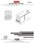
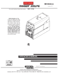
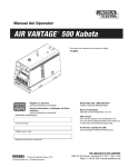
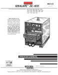
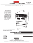
AIR VANTAGE ® 500 KUBOTA
For use with machine having Code Number:
November, 2010
11470
Safety Depends on You
Lincoln arc welding and cutting
equipment is designed and built
with safety in mind. However,
your overall safety can be
increased by proper installation ...
and thoughtful operation on your
part. DO NOT INSTALL, OPERATE OR REPAIR THIS EQUIPMENT WITHOUT READING
THIS MANUAL AND THE
SAFETY PRECAUTIONS CONTAINED THROUGHOUT. And,
most importantly, think before you
act and be careful.
OPERATOR’S MANUAL
Copyright © Lincoln Global Inc.
• World's Leader in Welding and Cutting Products •
• Sales and Service through Subsidiaries and Distributors Worldwide •
Cleveland, Ohio 44117-1199 U.S.A. TEL: 216.481.8100 FAX: 216.486.1751 WEB SITE: www.lincolnelectric.com
i
i
SAFETY
WARNING
CALIFORNIA PROPOSITION 65 WARNINGS
Diesel engine exhaust and some of its constituents
are known to the State of California to cause cancer, birth defects, and other reproductive harm.
The Above For Diesel Engines
The engine exhaust from this product contains
chemicals known to the State of California to cause
cancer, birth defects, or other reproductive harm.
The Above For Gasoline Engines
ARC WELDING CAN bE HAzARDOUS. PROTECT YOURSELF AND OTHERS FROM POSSIbLE SERIOUS INJURY OR DEATH.
KEEP CHILDREN AWAY. PACEMAKER WEARERS SHOULD CONSULT WITH THEIR DOCTOR bEFORE OPERATING.
Read and understand the following safety highlights. For additional safety information, it is strongly recommended that you
purchase a copy of “Safety in Welding & Cutting - ANSI Standard Z49.1” from the American Welding Society, P.O. Box
351040, Miami, Florida 33135 or CSA Standard W117.2-1974. A Free copy of “Arc Welding Safety” booklet E205 is available
from the Lincoln Electric Company, 22801 St. Clair Avenue, Cleveland, Ohio 44117-1199.
bE SURE THAT ALL INSTALLATION, OPERATION, MAINTENANCE AND REPAIR PROCEDURES ARE
PERFORMED ONLY bY QUALIFIED INDIVIDUALS.
FOR ENGINE
powered equipment.
1.h. To avoid scalding, do not remove the
radiator pressure cap when the engine is
hot.
1.a. Turn the engine off before troubleshooting and maintenance
work unless the maintenance work requires it to be running.
____________________________________________________
1.b. Operate engines in open, well-ventilated
areas or vent the engine exhaust fumes
outdoors.
____________________________________________________
1.c. Do not add the fuel near an open flame
welding arc or when the engine is running.
Stop the engine and allow it to cool before
refueling to prevent spilled fuel from vaporizing on contact with hot engine parts and
igniting. Do not spill fuel when filling tank. If
fuel is spilled, wipe it up and do not start
engine until fumes have been eliminated.
____________________________________________________
1.d. Keep all equipment safety guards, covers and devices in
position and in good repair.Keep hands, hair, clothing and
tools away from V-belts, gears, fans and all other moving
parts when starting, operating or repairing equipment.
____________________________________________________
1.e. In some cases it may be necessary to remove safety
guards to perform required maintenance. Remove
guards only when necessary and replace them when the
maintenance requiring their removal is complete.
Always use the greatest care when working near moving
parts.
___________________________________________________
1.f. Do not put your hands near the engine fan.
Do not attempt to override the governor or
idler by pushing on the throttle control rods
while the engine is running.
___________________________________________________
1.g. To prevent accidentally starting gasoline engines while
turning the engine or welding generator during maintenance
work, disconnect the spark plug wires, distributor cap or
magneto wire as appropriate.
ELECTRIC AND
MAGNETIC FIELDS
may be dangerous
2.a. Electric current flowing through any conductor causes
localized Electric and Magnetic Fields (EMF). Welding
current creates EMF fields around welding cables and
welding machines
2.b. EMF fields may interfere with some pacemakers, and
welders having a pacemaker should consult their physician
before welding.
2.c. Exposure to EMF fields in welding may have other health
effects which are now not known.
2.d. All welders should use the following procedures in order to
minimize exposure to EMF fields from the welding circuit:
2.d.1. Route the electrode and work cables together - Secure
them with tape when possible.
2.d.2. Never coil the electrode lead around your body.
2.d.3. Do not place your body between the electrode and
work cables. If the electrode cable is on your right
side, the work cable should also be on your right side.
2.d.4. Connect the work cable to the workpiece as close as
possible to the area being welded.
2.d.5. Do not work next to welding power source.
ii
ii
SAFETY
ELECTRIC SHOCK can
kill.
3.a. The electrode and work (or ground) circuits
are electrically “hot” when the welder is on.
Do not touch these “hot” parts with your bare
skin or wet clothing. Wear dry, hole-free
gloves to insulate hands.
3.b. Insulate yourself from work and ground using dry insulation.
Make certain the insulation is large enough to cover your full
area of physical contact with work and ground.
In addition to the normal safety precautions, if welding
must be performed under electrically hazardous
conditions (in damp locations or while wearing wet
clothing; on metal structures such as floors, gratings or
scaffolds; when in cramped positions such as sitting,
kneeling or lying, if there is a high risk of unavoidable or
accidental contact with the workpiece or ground) use
the following equipment:
• Semiautomatic DC Constant Voltage (Wire) Welder.
• DC Manual (Stick) Welder.
• AC Welder with Reduced Voltage Control.
3.c. In semiautomatic or automatic wire welding, the electrode,
electrode reel, welding head, nozzle or semiautomatic
welding gun are also electrically “hot”.
3.d. Always be sure the work cable makes a good electrical
connection with the metal being welded. The connection
should be as close as possible to the area being welded.
3.e. Ground the work or metal to be welded to a good electrical
(earth) ground.
3.f. Maintain the electrode holder, work clamp, welding cable and
welding machine in good, safe operating condition. Replace
damaged insulation.
3.g. Never dip the electrode in water for cooling.
3.h. Never simultaneously touch electrically “hot” parts of
electrode holders connected to two welders because voltage
between the two can be the total of the open circuit voltage
of both welders.
3.i. When working above floor level, use a safety belt to protect
yourself from a fall should you get a shock.
ARC RAYS can burn.
4.a. Use a shield with the proper filter and cover
plates to protect your eyes from sparks and
the rays of the arc when welding or observing
open arc welding. Headshield and filter lens
should conform to ANSI Z87. I standards.
4.b. Use suitable clothing made from durable flame-resistant
material to protect your skin and that of your helpers from
the arc rays.
4.c. Protect other nearby personnel with suitable, non-flammable
screening and/or warn them not to watch the arc nor expose
themselves to the arc rays or to hot spatter or metal.
FUMES AND GASES
can be dangerous.
5.a. Welding may produce fumes and gases
hazardous to health. Avoid breathing these
fumes and gases. When welding, keep
your head out of the fume. Use enough
ventilation and/or exhaust at the arc to keep
fumes and gases away from the breathing zone. When
welding with electrodes which require special
ventilation such as stainless or hard facing (see
instructions on container or MSDS) or on lead or
cadmium plated steel and other metals or coatings
which produce highly toxic fumes, keep exposure as
low as possible and within applicable OSHA PEL and
ACGIH TLV limits using local exhaust or mechanical
ventilation. In confined spaces or in some circumstances, outdoors, a respirator may be required.
Additional precautions are also required when welding
on galvanized steel.
5. b. The operation of welding fume control equipment is affected
by various factors including proper use and positioning of
the equipment, maintenance of the equipment and the specific welding procedure and application involved. Worker
exposure level should be checked upon installation and
periodically thereafter to be certain it is within applicable
OSHA PEL and ACGIH TLV limits.
5.c. Do not weld in locations near chlorinated hydrocarbon vapors
coming from degreasing, cleaning or spraying operations.
The heat and rays of the arc can react with solvent vapors to
form phosgene, a highly toxic gas, and other irritating products.
3.j. Also see Items 6.c. and 8.
5.d. Shielding gases used for arc welding can displace air and
cause injury or death. Always use enough ventilation,
especially in confined areas, to insure breathing air is safe.
5.e. Read and understand the manufacturer’s instructions for this
equipment and the consumables to be used, including the
material safety data sheet (MSDS) and follow your
employer’s safety practices. MSDS forms are available from
your welding distributor or from the manufacturer.
5.f. Also see item 1.b.
iii
iii
SAFETY
WELDING and CUTTING
SPARKS can
cause fire or explosion.
6.a. Remove fire hazards from the welding area.
If this is not possible, cover them to prevent
the welding sparks from starting a fire.
Remember that welding sparks and hot
materials from welding can easily go through small cracks
and openings to adjacent areas. Avoid welding near
hydraulic lines. Have a fire extinguisher readily available.
6.b. Where compressed gases are to be used at the job site,
special precautions should be used to prevent hazardous
situations. Refer to “Safety in Welding and Cutting” (ANSI
Standard Z49.1) and the operating information for the
equipment being used.
6.c. When not welding, make certain no part of the electrode
circuit is touching the work or ground. Accidental contact
can cause overheating and create a fire hazard.
6.d. Do not heat, cut or weld tanks, drums or containers until the
proper steps have been taken to insure that such procedures
will not cause flammable or toxic vapors from substances
inside. They can cause an explosion even though they have
been “cleaned”. For information, purchase “Recommended
Safe Practices for the Preparation for Welding and Cutting of
Containers and Piping That Have Held Hazardous
Substances”, AWS F4.1 from the American Welding Society
(see address above).
6.e. Vent hollow castings or containers before heating, cutting or
welding. They may explode.
6.f. Sparks and spatter are thrown from the welding arc. Wear oil
free protective garments such as leather gloves, heavy shirt,
cuffless trousers, high shoes and a cap over your hair. Wear
ear plugs when welding out of position or in confined places.
Always wear safety glasses with side shields when in a
welding area.
6.g. Connect the work cable to the work as close to the welding
area as practical. Work cables connected to the building
framework or other locations away from the welding area
increase the possibility of the welding current passing
through lifting chains, crane cables or other alternate circuits. This can create fire hazards or overheat lifting chains
or cables until they fail.
6.h. Also see item 1.c.
CYLINDER may explode
if damaged.
7.a. Use only compressed gas cylinders
containing the correct shielding gas for the
process used and properly operating
regulators designed for the gas and
pressure used. All hoses, fittings, etc. should be suitable for
the application and maintained in good condition.
7.b. Always keep cylinders in an upright position securely
chained to an undercarriage or fixed support.
7.c. Cylinders should be located:
• Away from areas where they may be struck or subjected to
physical damage.
• A safe distance from arc welding or cutting operations and
any other source of heat, sparks, or flame.
7.d. Never allow the electrode, electrode holder or any other
electrically “hot” parts to touch a cylinder.
7.e. Keep your head and face away from the cylinder valve outlet
when opening the cylinder valve.
7.f. Valve protection caps should always be in place and hand
tight except when the cylinder is in use or connected for
use.
7.g. Read and follow the instructions on compressed gas
cylinders, associated equipment, and CGA publication P-l,
“Precautions for Safe Handling of Compressed Gases in
Cylinders,” available from the Compressed Gas Association
1235 Jefferson Davis Highway, Arlington, VA 22202.
FOR ELECTRICALLY
powered equipment.
8.a. Turn off input power using the disconnect
switch at the fuse box before working on
the equipment.
8.b. Install equipment in accordance with the U.S. National
Electrical Code, all local codes and the manufacturer’s
recommendations.
8.c. Ground the equipment in accordance with the U.S. National
Electrical Code and the manufacturer’s recommendations.
6.I. Read and follow NFPA 51B “ Standard for Fire Prevention
During Welding, Cutting and Other Hot Work”, available
from NFPA, 1 Batterymarch Park, PO box 9101, Quincy, Ma
022690-9101.
6.j. Do not use a welding power source for pipe thawing.
Refer to http://www.lincolnelectric.com/safety for additional safety information.
iv
SAFETY
PRÉCAUTIONS DE SÛRETÉ
Pour votre propre protection lire et observer toutes les instructions
et les précautions de sûreté specifiques qui parraissent dans ce
manuel aussi bien que les précautions de sûreté générales suivantes:
Sûreté Pour Soudage A L’Arc
1. Protegez-vous contre la secousse électrique:
a. Les circuits à l’électrode et à la piéce sont sous tension
quand la machine à souder est en marche. Eviter toujours
tout contact entre les parties sous tension et la peau nue
ou les vétements mouillés. Porter des gants secs et sans
trous pour isoler les mains.
b. Faire trés attention de bien s’isoler de la masse quand on
soude dans des endroits humides, ou sur un plancher
metallique ou des grilles metalliques, principalement dans
les positions assis ou couché pour lesquelles une grande
partie du corps peut être en contact avec la masse.
c. Maintenir le porte-électrode, la pince de masse, le câble
de soudage et la machine à souder en bon et sûr état
defonctionnement.
d.Ne jamais plonger le porte-électrode dans l’eau pour le
refroidir.
e. Ne jamais toucher simultanément les parties sous tension
des porte-électrodes connectés à deux machines à souder
parce que la tension entre les deux pinces peut être le
total de la tension à vide des deux machines.
f. Si on utilise la machine à souder comme une source de
courant pour soudage semi-automatique, ces precautions
pour le porte-électrode s’applicuent aussi au pistolet de
soudage.
2. Dans le cas de travail au dessus du niveau du sol, se protéger
contre les chutes dans le cas ou on recoit un choc. Ne jamais
enrouler le câble-électrode autour de n’importe quelle partie
du corps.
3. Un coup d’arc peut être plus sévère qu’un coup de soliel,
donc:
a. Utiliser un bon masque avec un verre filtrant approprié
ainsi qu’un verre blanc afin de se protéger les yeux du rayonnement de l’arc et des projections quand on soude ou
quand on regarde l’arc.
b. Porter des vêtements convenables afin de protéger la
peau de soudeur et des aides contre le rayonnement de
l‘arc.
c. Protéger l’autre personnel travaillant à proximité au
soudage à l’aide d’écrans appropriés et non-inflammables.
4. Des gouttes de laitier en fusion sont émises de l’arc de
soudage. Se protéger avec des vêtements de protection libres
de l’huile, tels que les gants en cuir, chemise épaisse, pantalons sans revers, et chaussures montantes.
5. Toujours porter des lunettes de sécurité dans la zone de
soudage. Utiliser des lunettes avec écrans lateraux dans les
zones où l’on pique le laitier.
iv
6. Eloigner les matériaux inflammables ou les recouvrir afin de
prévenir tout risque d’incendie dû aux étincelles.
7. Quand on ne soude pas, poser la pince à une endroit isolé de
la masse. Un court-circuit accidental peut provoquer un
échauffement et un risque d’incendie.
8. S’assurer que la masse est connectée le plus prés possible
de la zone de travail qu’il est pratique de le faire. Si on place
la masse sur la charpente de la construction ou d’autres
endroits éloignés de la zone de travail, on augmente le risque
de voir passer le courant de soudage par les chaines de levage, câbles de grue, ou autres circuits. Cela peut provoquer
des risques d’incendie ou d’echauffement des chaines et des
câbles jusqu’à ce qu’ils se rompent.
9. Assurer une ventilation suffisante dans la zone de soudage.
Ceci est particuliérement important pour le soudage de tôles
galvanisées plombées, ou cadmiées ou tout autre métal qui
produit des fumeés toxiques.
10. Ne pas souder en présence de vapeurs de chlore provenant
d’opérations de dégraissage, nettoyage ou pistolage. La
chaleur ou les rayons de l’arc peuvent réagir avec les vapeurs
du solvant pour produire du phosgéne (gas fortement toxique)
ou autres produits irritants.
11. Pour obtenir de plus amples renseignements sur la sûreté,
voir le code “Code for safety in welding and cutting” CSA
Standard W 117.2-1974.
PRÉCAUTIONS DE SÛRETÉ POUR
LES MACHINES À SOUDER À
TRANSFORMATEUR ET À
REDRESSEUR
1. Relier à la terre le chassis du poste conformement au code de
l’électricité et aux recommendations du fabricant. Le dispositif
de montage ou la piece à souder doit être branché à une
bonne mise à la terre.
2. Autant que possible, I’installation et l’entretien du poste seront
effectués par un électricien qualifié.
3. Avant de faires des travaux à l’interieur de poste, la debrancher à l’interrupteur à la boite de fusibles.
4. Garder tous les couvercles et dispositifs de sûreté à leur
place.
v
v
Thank You
for selecting a QUALITY product by Lincoln Electric. We want you
to take pride in operating this Lincoln Electric Company product
••• as much pride as we have in bringing this product to you!
CUSTOMER ASSISTANCE POLICY
The business of The Lincoln Electric Company is manufacturing and selling high quality welding equipment, consumables, and cutting equipment. Our challenge is to meet the needs of our customers and to exceed their expectations. On occasion, purchasers may ask Lincoln
Electric for advice or information about their use of our products. We respond to our customers based on the best information in our possession at that time. Lincoln Electric is not in a position to warrant or guarantee such advice, and assumes no liability, with respect to such information or advice. We expressly disclaim any warranty of any kind, including any warranty of fitness for any customer’s particular purpose,
with respect to such information or advice. As a matter of practical consideration, we also cannot assume any responsibility for updating or
correcting any such information or advice once it has been given, nor does the provision of information or advice create, expand or alter any
warranty with respect to the sale of our products.
Lincoln Electric is a responsive manufacturer, but the selection and use of specific products sold by Lincoln Electric is solely within the control
of, and remains the sole responsibility of the customer. Many variables beyond the control of Lincoln Electric affect the results obtained in
applying these types of fabrication methods and service requirements.
Subject to Change – This information is accurate to the best of our knowledge at the time of printing. Please refer to www.lincolnelectric.com
for any updated information.
Please Examine Carton and Equipment For Damage Immediately
When this equipment is shipped, title passes to the purchaser upon receipt by the carrier. Consequently, Claims
for material damaged in shipment must be made by the purchaser against the transportation company at the
time the shipment is received.
Please record your equipment identification information below for future reference. This information can be
found on your machine nameplate.
Product _________________________________________________________________________________
Model Number ___________________________________________________________________________
Code Number or Date Code_________________________________________________________________
Serial Number____________________________________________________________________________
Date Purchased___________________________________________________________________________
Where Purchased_________________________________________________________________________
Whenever you request replacement parts or information on this equipment, always supply the information you
have recorded above. The code number is especially important when identifying the correct replacement parts.
On-Line Product Registration
- Register your machine with Lincoln Electric either via fax or over the Internet.
• For faxing: Complete the form on the back of the warranty statement included in the literature packet
accompanying this machine and fax the form per the instructions printed on it.
• For On-Line Registration: Go to our WEb SITE at www.lincolnelectric.com. Choose “Quick Links” and then
“Product Registration”. Please complete the form and submit your registration.
Read this Operators Manual completely before attempting to use this equipment. Save this manual and keep it
handy for quick reference. Pay particular attention to the safety instructions we have provided for your protection.
The level of seriousness to be applied to each is explained below:
WARNING
This statement appears where the information must be followed exactly to avoid serious personal injury or loss of life.
CAUTION
This statement appears where the information must be followed to avoid minor personal injury or damage to this equipment.
vi
vi
TAbLE OF CONTENTS
Page
Installation.......................................................................................................................Section A
Technical Specifications .......................................................................................................A-1
Machine Specification ...................................................................................................A-2
Safety Precautions ........................................................................................................A-2
Location and Ventilation ................................................................................................A-2
Storing ...........................................................................................................................A-2
Stacking ........................................................................................................................A-2
Angle of Operation ........................................................................................................A-2
Lifting.............................................................................................................................A-3
High Altitude Operation .................................................................................................A-3
High Temperature Operation ........................................................................................A-3
Cold Weather Operation ......................................................................................................A-3
Towing...........................................................................................................................A-3
Vehicle Mounting...........................................................................................................A-3
Pre-Operation Engine and Compressor Service ..................................................................A-4
Oil ..................................................................................................................................A-4
Fuel and Fuel Cap.........................................................................................................A-4
Engine Coolant System.................................................................................................A-4
Battery Connections ......................................................................................................A-4
Muffler Outlet Pipe ........................................................................................................A-5
Spark Arrestor ...............................................................................................................A-5
Air Cleaner Inlet Hood ..........................................................................................................A-5
Welding Terminals................................................................................................................A-5
Welding Output Cables .................................................................................................A-5
Machine Grounding .......................................................................................................A-5
Remote Control ....................................................................................................................A-6
Auxiliary Power Receptacles and Plugs ...............................................................................A-6
Standby Power Connections ................................................................................................A-7
Premises Wiring ...................................................................................................................A-8
Connection of Lincoln Electric Wire Feeders..............................................................A-9, A-10
________________________________________________________________________________
Operation.........................................................................................................................Section b
Safety Precautions ..............................................................................................................B-1
General Description..............................................................................................................B-1
For Auxiliary Power ..............................................................................................................B-1
Engine Operation..................................................................................................................B-1
Add Fuel ...............................................................................................................................B-1
Break in Period .....................................................................................................................B-1
Recommended Application - Welder, Air Compressor and Generator.................................B-2
Welder Controls .............................................................................................................B-3,B-4
Engine Controls .............................................................................................................B-5,B-6
Starting and Stopping the Engine ...........................................................................B-6,B-7
Welding Operation................................................................................................................B-7
Duty Cycle and Electrode Information...........................................................................B-7
Constant Current (Stick) Welding .........................................................................................B-7
Downhill Pipe (Stick) Welding ...................................................................................... B-8
TIG Welding ..................................................................................................................B-8
Wire Welding-CV...........................................................................................................B-9
Arc Gouging ..................................................................................................................B-9
Typical Current Ranges for Tungsten Electrodes .........................................................B-9
Paralleling...........................................................................................................................B-10
Auxiliary Power...................................................................................................................B-10
Simultaneous Welding and Power Loads ...................................................................B-10
Extension Cord Recommendations.............................................................................B-10
________________________________________________________________________________
Accessories .....................................................................................................Section C
Field Installed Options / Accessories ...............................................................................C-1
________________________________________________________________________________
vii
TAbLE OF CONTENTS
Maintenance......................................................................................................Section D
Safety Precautions ................................................................................................D-1
Routine Maintenance, Daily and Weekly ..............................................................D-1
Compressor Maintenance .....................................................................................D-1
Vehicle Mounted Air Compressors ........................................................................D-1
Engine Maintenance..............................................................................................D-1
Air Filter .................................................................................................................D-1
Service Instructions And Installation Tips for Engine Air Filter ..............................D-2
Engine Oil Change..........................................................................................D-3
Engine Oil Filter Change.................................................................................D-3
Air Cleaner .....................................................................................................D-3
Cooling System .....................................................................................................D-4
Fan Belt...........................................................................................................D-4
Fuel .................................................................................................................D-4
Bleeding the Fuel System ...............................................................................D-4
Fuel Filter ........................................................................................................D-5
Engine Adjustment ..........................................................................................D-5
Battery Maintenance .......................................................................................D-5
Servicing Optional Spark Arrestor ...................................................................D-5
Welder / Generator Maintenance ........................................................................D-6
Storage ...........................................................................................................D-6
Cleaning..........................................................................................................D-6
Brush Removal and Replacement ..................................................................D-6
GFCI Testing and Setting ......................................................................................D-6
________________________________________________________________________
Troubleshooting ..............................................................................................Section E
________________________________________________________________________
Connection Diagrams, Wiring Diagrams and Dimension Print...................Section F
________________________________________________________________________
Parts List .....................................................................................................P-625 Series
________________________________________________________________________
vii
A-1
A-1
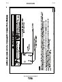
INSTALLATION
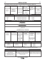
TECHNICAL SPECIFICATIONS - AIR VANTAGE® 500 KUbOTA (K2325 -2)
INPUT - DIESEL ENGINE
Make/Model
KUBOTA
V3600-T
Description
Speed (RPM)
4 cylinder
58 HP (43.2kw)
1850 RPM
Diesel Engine
High Idle 1850
Full Load 1850
Low Idle 1425
Displacement
cu. in. (ltrs.)
220.9(3.62)
Starting
System
12VDC Battery &
starter
Bore x Stroke inch (mm)
3.86 X 4.72
Capacities
Fuel: 25 gal.
(94.6 L)
Oil: 3.5gal. (13.2L)
Radiator Coolant:
2.6gal. (9.8L)
(98 x 120mm)
RATED OUTPUT @ 104°F(40°C) - WELDER
Duty Cycle
Welding Output
Volts at Rated Amps
100%
60%
50%
500 Amps (DC multi-purpose)
550 Amps (DC multi-purpose)
575 Amps (DC multi-purpose)
40 Volts
36 volts
35 volts
OUTPUT @ 104°F(40°C) - WELDER AND GENERATOR
Welding Range
30 - 575 Amps CC/CV
20 - 250 Amps TIG
Open Circuit Voltage
60 Max OCV @ 1850 RPM
Auxiliary Power (1)
120/240 VAC
12,000 WATTS, 60 Hz., Single Phase
20,000 WATTS, 60 Hz., Three Phase
COMPRESSOR SPECIFICATIONS
Compressor Model
VMAC™
S700066
Description
Delivary
Maximum System Compressor
Pressure
Profection
Direct-Drive Rotary High Idle Mode:
150 PSI
Safety Relief Valve
Screw Air Compressor 60 CFM @ 100PSI
(10.5 kg/cm2)
200 PSI
(28.3 Ltr/sec. @
(10.5 kg/cm2)
7.0 kg/cm)
Low Idle Mode:
40 CFM @ 100PSI
(18.9 Ltr/sec. @
7.0 kg/cm)
Capacities
1.3 gal.(5.0 ltrs)
High Temperature
Automatic Shutdown
290° F (143°C)
PHYSICAL DIMENSIONS
1.
2.
Height (2)
Width
Depth
Weight
42.0 in
(1066.8 mm)
32.7 in.
(830.1mm)
63.1 in.
(1603mm)
1730 lbs.
(785kg)
(Approx)
Output rating in watts is equivalent to volt-amperes at unity power factor.
Output voltage is within +/- 10% at all loads up to rated capacity. When welding, available auxiliary power will be reduced.
Top of Enclosure, add 7.0” (177.8mm) for exhaust pipe.
MACHINE SPECIFICATIONS
RECEPTACLES
(2)120VAC Duplex (5-20R)
GFCI Protected
(1) 120/240 VAC Dual Voltage
Full KVA (14-50R)
(1) 240VAC 3-Phase (15-50R)
AUXILIARY POWER CIRCUIT breaker
OTHER CIRCUIT bREAKERS
Two 20AMP for Two Duplex Receptacle 10AMP for Battery Charging Circuit
10AMP for 42V Wire Feeder Power
(1) 50AMP for Dual Voltage and for
3-Phase (3-pole)
AIR VANTAGE® 500 KUbOTA
A-2
A-2
INSTALLATION
SAFETY PRECAUTIONS
LOCATION AND VENTILATION
WARNING
Do not attempt to use this equipment until you
have thoroughly read the engine manufacturer’s
manual supplied with your welder. It includes
important safety precautions, detailed engine
starting, operating and maintenance instructions,
and parts lists.
-----------------------------------------------------------------------ELECTRIC SHOCK can kill.
• Do not touch electrically live parts or
electrode with skin or wet clothing.
• Insulate yourself from work and
ground
• Always wear dry insulating gloves.
-----------------------------------------------------------------------ENGINE EXHAUST can kill.
• Use in open, well ventilated areas or
vent exhaust outside.
-----------------------------------------------------------------------MOVING PARTS can injure.
• Do not operate with doors open or
guards off.
• Stop engine before servicing.
• Keep away from moving parts.
------------------------------------------------------------------------
The welder should be located to provide an unrestricted flow of clean, cool air to the cooling air inlets and to
avoid restricting the cooling air outlets. Also, locate
the welder so that the engine exhaust fumes are properly vented to an outside area.
CAUTION
DO NOT MOUNT OVER COMbUSTIbLE SURFACES
Where there is a combustible surface directly
under stationary or fixed electrical equipment, that
surface should be covered with a steel plate at
least .06”(1.6mm) thick, which should extend not
less than 5.90”(150mm) beyond the equipment on
all sides.
------------------------------------------------------------------------
STORING
1.
Store the machine in a cool, dry place when it is
not in use. Protect it from dust and dirt. Keep it
where it can’t be accidentally damaged from construction activities, moving vehicles, and other
hazards.
2.
Only qualified personnel should install,
use, or service this equipment.
VRD (VOLTAGE REDUCTION DEVICE)
Drain the engine oil and refill with fresh 10W30
oil. Run the engine for about five minutes to circulate oil to all the parts. See the MAINTENANCE section of this manual for details on
changing oil.
3.
The VRD feature provides additional safety in the CC-Stick
mode especially in an environment with a higher risk of
electric shock such as wet areas and hot humid sweaty
conditions.
Remove the battery, recharge it, and adjust the
electrolyte level. Store the battery in a dry, dark
place.
STACKING
See additional warning information at
front of this operator’s manual.
The VRD reduces the OCV (Open Circuit Voltage) at the
welding output terminals while not welding to less than 13V
DC when the resistance of the output circuit is above 200Ω
(ohms).
The VRD requires that the welding cable connections be
kept in good electrical condition because poor connections
will contribute to poor starting. Having good electrical connections also limits the possibility of other safety issues
such as heat-generated damage, burns and fires.
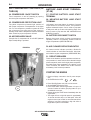
The machine is shipped with the VRD switch in the “Off”
position. To turn it “On” or “Off”.
• Turn the engine “Off”.
• Disconnect the negative battery cable.
• Lower the control panel by removing 4 front
panel screws. (See Figure A.1)
• Place the VRD switch in the “On” or “Off” position.
(See Figure A.1)
With the VRD switch in the “On” position, the VRD lights
are enabled.
AIR VANTAGE® 500 KUBOTA machines cannot be
stacked.
ANGLE OF OPERATION
To achieve optimum engine performance the Air
Vantage 500 should be run in a level position. The
maximum angle of operation for the VMAC
Compressor and KUBOTA engine is 20 degrees continues in all directions and 30 degrees intermittent
(less than 10 minutes). When operating the welder at
an angle, provisions must be made for checking and
maintaining the oil level at the normal (FULL) oil
capacity. Also the effective fuel capacity will be slightly
less than the specified 25 gal.(94.6 ltrs.).
AIR VANTAGE® 500 KUbOTA
A-3
A-3
INSTALLATION
LIFTING
TOWING
The AIR VANTAGE® 500 KUBOTA lift bale should be
used to lift the machine. The Air Vantage 500 is
shipped with the lift bale retracted. Before attempting
to lift the AIR VANTAGE® 500 KUBOTA the lift bale must
be secured in a raised position. Secure the lift bale as
follows:
The recommended trailer for use with this equipment
for road, in-plant and yard towing by a vehicle (1) is
Lincoln’s K2641-2. If the user adapts a non-Lincoln
trailer, he must assume responsibility that the method
of attachment and usage does not result in a safety
hazard nor damage the welding equipment. Some of
the factors to be considered are as follows:
a. Open the engine compartment door.
b. Locate the 2 access holes on the upper middle
region of compartment wall just below the lift
bale.
c. Use the lifting strap to raise the lift bale to the
full upright position. This will align the mounting holes on the lift bale with the access holes.
d. Secure the lift bale with 2 thread forming
screws. The screws are provided in the
shipped loose parts bag.
WARNING
• be sure machine is stable when lifting.
• Do not lift this machine using lift
bail if it is equipped with a heavy
accessory such as trailer or gas
cylinder.
EQUIPMENT can
cause injury.
2. Proper support of, and attachment to, the base of
the welding equipment so that there will be no
undue stress to the trailer’s framework.
3. Proper placement of the equipment on the trailer
to insure stability side to side and front to back
when being moved and when standing by itself.
4. Typical conditions of use, such as travel speed,
roughness of surface on which the trailer will be
operated, and environmental conditions.
5. Proper preventative maintenance of trailer.
• Lift only with equipment of adequate lifting capacity.
FALLING
1. Design capacity of trailer vs. weight of Lincoln
equipment and likely additional attachments.
6. Conformance with federal, state and local laws (1) .
(1)
Consult applicable federal, state and local laws
regarding specific requirements for use on public
highways.
VEHICLE MOUNTING
• Do not lift machine if lift bail is
WARNING
damaged.
• Do not operate machine while
suspended from lift bail.
--------------------------------------------------------------------------------
HIGH ALTITUDE OPERATION
At higher altitudes, output derating may be necessary.
For maximum rating, derate the welder output 5% for
every 500 meters (1640ft.) above 400 meters (1312
ft.).
Contact a KUBOTA Service Representative for any
engine adjustments that may be required.
HIGH TEMPERATURE OPERATION
Improperly mounted concentrated loads may
cause unstable vehicle handling and tires or other
components to fail.
• Only transport this Equipment on serviceable
vehicles which are rated and designed for such
loads.
• Distribute, balance and secure loads so vehicle
is stable under conditions of use.
• Do not exceed maximum rated loads for components such as suspension, axles and tires.
• Mount equipment base to metal bed or frame of
vehicle.
• Follow vehicle manufacture’s instructions.
--------------------------------------------------------------------------------
At temperatures above 40°C (104°F), output voltage
derating may be necessary. For maximum output current ratings, derate welder voltage rating 2 volts for
every 10°C (21°F) above 40°C (104°F).
AIR VANTAGE® 500 KUbOTA
A-4
A-4
INSTALLATION
PRE-OPERATION ENGINE AND COMPRESSOR SERVICE
READ the engine and compressor operating and
maintenance instructions supplied with this machine.
ENGINE COOLANT
WARNING
HOT COOLANT can burn skin.
•Do not remove cap if radiator is hot.
WARNING
• Keep hands away from the engine
muffler or HOT engine parts.
• Stop engine and allow to cool before
fuelling.
• Do not smoke when fuelling.
• Fill fuel tank at a moderate rate and do not overfill.
--------------------------------------------------------------------------------
The welder is shipped with the engine and radiator
filled with a 50% mixture of ethylene glycol and water.
See the MAINTENANCE section and the engine
Operator’s Manual for more information on coolant.
bATTERY CONNECTION
• Wipe up spilled fuel and allow fumes to clear
before starting engine.
GASES FROM bATTERY can explode.
• Keep sparks and flame away from tank.
• Keep sparks, flame and cigarettes
away from battery.
--------------------------------------------------------------------------------
OIL
The AIR VANTAGE® 500 KUBOTA is shipped with
the engine crankcase filled with high quality SAE
10W-30 oil (API class CD or better). Check the engine
and compressor oil levels before starting the engine. If
it is not up to the full mark on the dip stick, add oil as
required. Check the oil level every four hours of running time during the first 35 running hours. Refer to
the engine and compressor Operator’s Manuals for
specific oil recommendations and break-in information. The oil change interval is dependent on the quality of the oil and the operating environment. Refer to
the engine and compressor Operator’s Manuals for
the proper service and maintenance intervals.
To prevent EXPLOSION when:
• INSTALLING A NEW bATTERY — disconnect
negative cable from old battery first and connect
to new battery last.
• CONNECTING A bATTERY CHARGER — remove
battery from welder by disconnecting negative
cable first, then positive cable and battery clamp.
When reinstalling, connect negative cable last.
Keep well ventilated.
• USING A bOOSTER — connect positive lead to
battery first then connect negative lead to negative battery lead at engine foot.
bATTERY ACID can burn eyes and skin.
• Wear gloves and eye protection and be
careful when working near battery.
FUEL
USE DIESEL FUEL ONLY
Low Sulphur fuel or ultra low sulphur fuel in USA and
CANADA only.
• Fill the fuel tank with clean, fresh diesel fuel.
The capacity of the fuel tank is approximately 25
gallons (95 liters). See engine Operator’s Manual
for specific fuel recommendations. Running out
of fuel may require bleeding the fuel injection
pump. NOTE: before starting the engine, open
the fuel shutoff valve (pointer to be in line with
hose).
• Follow instructions printed on battery.
IMPORTANT: To prevent ELECTRICAL DAMAGE
WHEN:
a) Installing new batteries.
b) Using a booster.
Use correct polarity — Negative Ground.
--------------------------------------------------------------------------------
FUEL CAP
Remove the plastic cap covering from the Fuel Tank
Filler neck and install the Fuel Cap.
AIR VANTAGE® 500 KUbOTA
A-5
A-5
INSTALLATION
The AIR VANTAGE® 500 KUBOTA is shipped with
the negative battery cable disconnected. Before you
operate the machine, make sure the Engine Switch is
in the OFF position and attach the disconnected cable
securely to the negative (-) battery terminal.
Remove the insulating cap from the negative battery
terminal. Replace and tighten negative battery cable
terminal. NOTE: This machine is furnished with a wet
charged battery; if unused for several months, the battery may require a booster charge. Be sure to use the
correct polarity when charging the battery.
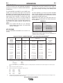
Listed in Table A.1 are copper cable sizes recommended for the rated current and duty cycle. Lengths
stipulated are the distance from the welder to work
and back to the welder again. Cable sizes are
increased for greater lengths primarily for the purpose
of minimizing cable voltage drop.
Table A.1 Combined Length of Electrode and
Work Cables.
TOTAL COMbINED LENGTH OF
ELECTRODE AND WORK CAbLES
Cable Length
MUFFLER OUTLET PIPE
Remove the plastic plug covering the muffler outlet
tube. Using the clamp provided secure the outlet pipe
to the outlet tube with the pipe positioned such that it
will direct the exhaust in the desired position.
0-150 Ft. (0-46 meters)
150-200 Ft. (46-61 meters)
200-250 Ft. (61-76 meters)
Cable Size for
500 Amps
100% Duty Cycle
3 / 0 AWG
3 / 0 AWG
4 / 0 AWG
SPARK ARRESTOR
MACHINE GROUNDING
Some federal, state or local laws may require that
petrol or diesel engines be equipped with exhaust
spark arrestors when they are operated in certain
locations where unarrested sparks may present a fire
hazard. The standard muffler included with this welder
has an internal spark arrestor. When required by local
regulations, a suitable spark arrestor, must be
installed and properly maintained.
To prevent dangerous electric shock, other equipment
to which this engine driven welder supplies power
must:
Because this portable engine driven welder creates its
own power, it is not necessary to connect its frame to
an earth ground, unless the machine is connected to
premises wiring (home, shop, etc.).
WARNING
CAUTION
An incorrect arrestor may lead to damage to the
engine or adversely affect performance.
--------------------------------------------------------------------------------
AIR CLEANER INLET HOOD
Remove the plastic plug covering the air cleaner inlet.
Install the air cleaner inlet hood to the air cleaner.
WELDING TERMINALS
The AIR VANTAGE® 500 KUBOTA is equipped with a
toggle switch for selecting "hot" welding terminals
when in the "WELD TERMINALS ON" position or
"cold" welding terminals when in the "REMOTELY
CONTROLLED" position.
WELDING OUTPUT CAbLES
With the engine off, route the electrode and work
cables thru the strain relief bracket provided on the
front of the base and connect to the terminals provided. These connections should be checked periodically
and tightened if necessary.
• be grounded to the frame of the welder using a
grounded type plug or be double insulated.
• Do not ground the machine to a pipe that carries
explosive or combustible material.
--------------------------------------------------------------------------------
When this welder is mounted on a truck or trailer, its
frame must be securely connected to the metal frame
of the vehicle. When this engine driven welder is connected to premises wiring such as that in a home or
shop, its frame must be connected to the system earth
ground. See further connection instructions in the section entitled “Standby Power Connections” as well as
the article on grounding in the latest National
Electrical Code and the local codes.
In general, if the machine is to be grounded, it should
be connected with a #8 or larger copper wire to a solid
earth ground such as a metal ground stake going into
the ground for at least 10 Feet or to the metal framework of a building which has been effectively grounded.
The National Electric Code lists a number of alternate
means of grounding electrical equipment. A machine
grounding stud marked with the symbol
is provided
on the front of the welder.
AIR VANTAGE® 500 KUbOTA
A-6
INSTALLATION
REMOTE CONTROL
The AIR VANTAGE® 500 KUBOTA is equipped with a
6-pin and a 14-pin connector. The 6-pin connector is
for connecting the K857 or K857-1 Remote Control or
for TIG welding, the K870 foot Amptrol or the K963-3
hand Amptrol. When in the CC-STICK, ARC GOUGING or CV-WIRE modes and when a remote control is
connected to the 6-pin Connector, the auto-sensing
circuit automatically switches the OUTPUT control
from control at the welder to remote control.
When in TOUCH START TIG mode and when a
Amptrol is connected to the 6-Pin Connector, the
OUTPUT dial is used to set the maximum current
range of the CURRENT CONTROL of the Amptrol.
When in the DOWNHILL PIPE mode and when a
remote control is connected to the 6-Pin or 14-Pin
connector, the output control is used to set the maximum current range of the remote.
EXAMPLE: When the OUTPUT CONTROL on the
welder is set to 200 amps the current range on the
remote control will be 40-200 amps, rather than the
full 40-300 amps. Any current range that is less than
the full range provides finer current resolution for more
fine tuning of the output.
In the CV-WIRE mode, if the feeder being used has a
voltage control when the wire feeder control cable is
connected to the 14-Pin Connector, the auto-sensing
circuit automatically makes OUTPUT CONTROL inactive and the wire feeder voltage control active.
Otherwise, the OUTPUT CONTROL is used to preset
the voltage.
The 14-pin connector is used to directly connect a
wire feeder control cable. In the CV-WIRE mode,
when the control cable is connected to the 14-pin connector, the auto-sensing circuit automatically makes
the Output Control inactive and the wire feeder voltage control active.
A-6
The auxiliary power of the AIR VANTAGE® 500 KUBOTA consists of two 20 Amp-120 VAC (5-20R) duplex
receptacles with GFCI protection, one 50 Amp 120/240
VAC (14-50R) receptacle and one 50 Amp 240VAC
Three-Phase (15-50R) receptacle.
The auxiliary power capacity is 13,000 watts Peak,
12,000 Watts Continuous of 60 Hz, single phase power.
The auxiliary power capacity rating in watts is equivalent
to volt-amperes at unity power factor. The max permissible current of the 240 VAC output is 50amps.
The 240 VAC output can be split to provide two separate
120 VAC outputs with a max permissible current of 50
Amps per output to two separate 120 VAC branch circuits (these circuits cannot be paralleled). Output voltage
is within ± 10% at all loads up to rated capacity.
The Three-Phases auxiliary power capacity is 22,000
watts peak, 20,000 watts continuous. The maximum current is 45 amps.
120 V DUPLEX RECEPTACLES AND GFCI MODULES
A GFCI Module protects the two 120V auxiliary power
receptacles.
A GFCI (Ground Fault Circuit Interrupter) is a device to
protect against electric shock should a piece of defective
equipment connected to it develop a ground fault. If this
situation should occur, the GFCI module will trip, removing voltage from the output of the receptacle. If a GFCI
module is tripped see the MAINTENANCE section for
detailed information on testing and resetting it. A GFCI
module should be properly tested at least once every
month.
The 120 V auxiliary power receptacles should only be
used with three wire grounded type plugs or approved
double insulated tools with two wire plugs. The current
rating of any plug used with the system must be at least
equal to the current capacity of the associated receptacle.
NOTE: The 240 V receptacle has two 120 V circuits, but
are of opposite polarities and cannot be paralleled.
WARNING
NOTE: When a wire feeder with a built in welding
voltage control is connected to the 14-pin connector, do not connect anything to the 6-pin connector.
--------------------------------------------------------------------------------
AUXILIARY POWER RECEPTACLES
All auxiliary power is protected by circuit breakers. The
120V has 20 Amp circuit breakers for each duplex receptacle. The 120/240V Single Phase and the 240V ThreePhases have a 50 Amp 3-pole Circuit Breaker that disconnects both hot leads and all Three Phases simultaneously.
Start the engine and set the “IDLER” control switch to the
“High Idle” mode. Voltage is now correct at the receptacles for auxiliary power. This must be done before a
tripped GFCI module can be reset properly. See the
MAINTENANCE section for more detailed information on
testing and resetting the GFCI module.
AIR VANTAGE® 500 KUbOTA
A-7
INSTALLATION
STANDbY POWER CONNECTIONS
The AIR VANTAGE® 500 KUBOTA is suitable for
temporary, standby or emergency power using the
engine manufacturer’s recommended maintenance
schedule.
The AIR VANTAGE® 500 KUBOTA can be permanently installed as a standby power unit for 240 VAC,
3 wire, single phase, 50 amp service. Connections
must be made by a licensed electrician who can
determine how the 120/240 VAC power can be adapted to the particular installation and comply with all
applicable electrical codes.
• Install the double-pole, double-throw switch
between the power company meter and the premises disconnect. Switch rating must be the same or
greater than the customer’s premises disconnect
and service over current protection.
• Take necessary steps to assure load is limited to
the capacity of the generator by installing a 50 amp,
240 VAC double pole circuit breaker. Maximum
rated load for each leg of the 240 VAC auxiliary is
50 amperes. Loading above the rated output will
reduce output voltage below the allowable - 10% of
rated voltage which may damage appliances or
other motor-driven equipment and may result in
overheating of the engine and/or alternator windings.
• Install a 50 amp, 120/240 VAC plug (NEMA Type
14-50P) to the double-pole circuit breaker using No.
6, 4 conductor cable of the desired length. (The 50
amp, 120/240 VAC plug is available in the optional
K802R plug kit or as part number T12153-9.)
• Plug this cable into the 50 Amp, 120/240 Volt receptacle on the case front.
WARNING
• Only a licensed, certified, trained electrician
should install the machine to a premises or residential electrical system. be certain that:
• The installation complies with the National
Electrical Code and all other applicable electrical codes.
• The premises is isolated and no feedback into
the utility system can occur. Certain laws require
the premises to be isolated before the generator
is linked to the premises. Check your local
requirements.
--------------------------------------------------------------------------------
AIR VANTAGE® 500 KUbOTA
A-7
A-8
INSTALLATION
A-8
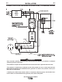
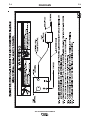
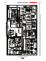
CONNECTION OF AIR VANTAGE® 500 KUbOTA 500 TO PREMISES WIRING
WARNING
• Only a licensed, certified, trained electrician should install the machine to a premises or residential
electrical system. be certain that:
• The installation complies with the National Electrical Code and all other applicable electrical codes.
• The premises is isolated and no feedback into the utility system can occur. Certain state and local
laws require the premises to be isolated before the generator is linked to the premises. Check your
state and local requirements.
• A double pole, double throw transfer switch in conjunction with the properly rated double throw
circuit breaker is connected between the generator power and the utility meter.
AIR VANTAGE® 500 KUbOTA
A-9
INSTALLATION
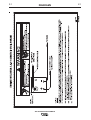
CONNECTION OF LINCOLN ELECTRIC WIRE FEEDERS
Connection of LN-7, LN-8 OR LN-742 to the AIR
VANTAGE® 500 KUbOTA
A-9
4. Control Cable Model:
• Connect Control Cable between Engine Welder
and Feeder.
1. Shut the welder off.
• Set the "WELD TERMINALS" switch to
"REMOTELY CONTROLLED"
2. Connect the LN-7, LN-8 OR LN-742 per instructions on the appropriate connection diagram in
Section F.
• Set the MODE switch to the "CV-WIRE " position.
3. Set the "WIRE FEEDER VOLTMETER" switch to
either "+" or "-" as required by the electrode being
used.
4. Set the "MODE" switch to the "CV WIRE " position.
5. Set the "ARC CONTROL" knob to "0" initially and
adjust to suit.
6. Set the "WELD TERMINALS" switch to the
"REMOTELY CONTROLLED" position.
7. Set the "IDLE" switch to the "HIGH" position.
Connection of LN-15 to the AIR VANTAGE® 500
KUbOTA
• Set the "WIRE FEEDER VOLTMETER" switch to
either "+" or "-" as required by the electrode polarity being used.
• Set the "ARC CONTROL" knob to "0" initially and
adjust to suit.
• Set the "IDLE" switch to the "AUTO" position.
• When the gun trigger is closed, the current sensing circuit will cause the AIR VANTAGE® 500
KUBOTA engine to go to the high idle speed, the
wire will begin to feed and the welding process
started. When welding is stopped, the engine will
revert to low idle speed after approximately 12
seconds unless welding is resumed.
1. Shut the welder off.
2. For electrode Positive, connect the electrode
cable to the "+" terminal of the welder and work
cable to the "-" terminal of the welder. For electrode Negative, connect the electrode cable to the
"-" terminal of the welder and work cable to the "+"
terminal of the welder.
3. Across The-Arc Model:
• Attach the single lead from the front of the LN-15
to work using the spring clip at the end of the
lead. This is a control lead to supply current to
the wire feeder motor; it does not carry welding
current.
• Set the "WELD TERMINALS" switch to "WELD
TERMINALS ON".
• When the gun trigger is closed, the current sensing circuit will cause the AIR VANTAGE® 500
KUBOTA engine to go to the high idle speed,
the wire will begin to feed and the welding
process started. When welding is stopped, the
engine will revert to low idle speed after approximately 12 seconds unless welding is resumed.
AIR VANTAGE® 500 KUbOTA
A-10
INSTALLATION
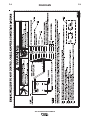
CONNECTION OF THE LN-25 TO THE AIR
VANTAGE® 500 KUbOTA.
WARNING
Shut off welder before making any electrical connections.
--------------------------------------------------------------------------------
The LN-25 with or without an internal contactor may
be used with the AIR VANTAGE® 500 KUBOTA . See
the appropriate connection diagram in Section F.
1. Shut the welder off.
2. For electrode Positive, connect the electrode
cable from the LN-25 to the "+" terminal of the
welder and work cable to the "-" terminal of the
welder. For electrode Negative, connect the electrode cable from the LN-25 to the "-" terminal of
the welder and work cable to the "+" terminal of
the welder.
3. Attach the single lead from the front of the LN-25
to work using the spring clip at the end of the lead.
This is a control lead to supply current to the wire
feeder motor; it does not carry welding current.
4. Set the MODE switch to the "CV-WIRE " position.
5. Set the "WELD TERMINALS" switch to "WELD
TERMINALS ON"
6. Set the "ARC CONTROL" knob to "0" initially and
adjust to suit.
7. Set the "IDLE" switch to the "AUTO" position.
When not welding, the AIR VANTAGE® 500 KUBOTA engine will be at the low idle speed. If you
are using an LN-25 with an internal contactor, the
electrode is not energized until the gun trigger is
closed.
8. When the gun trigger is closed, the current sensing circuit will cause the AIR VANTAGE® 500
KUBOTA engine to go to the high idle speed, the
wire will begin to feed and the welding process
started. When welding is stopped, the engine will
revert to low idle speed after approximately 12
seconds unless welding is resumed.
CAUTION
If you are using an LN-25 without an internal contactor, the electrode will be energized when the
AIR VANTAGE® 500 KUbOTA is started.
------------------------------------------------------------------------
A-10
CONNECTION OF AN NA-3 AUTOMATIC
WELDING SYSTEM TO THE AIR VANTAGE® 500 KUbOTA
For connection diagrams and instructions for connecting an NA-3 Welding System to the AIR VANTAGE®
500 KUBOTA, refer to the NA-3 Welding System
instruction manual. The connection diagram for the
LN-8 can be used for connecting the NA-3.
• Set the Wire Feeder Voltage Switch to 115V.
CONNECTION OF MAGNUM SC SPOOL
GUN TO THE AIR VANTAGE® 500 KUbOTA (SEE SECTION F)
CONNECTION OF PRINCE XL SPOOL
GUN TO THE AIR VANTAGE® 500 KUbOTA
Connection of the Prince XL Spool Gun requires the
use of the K1849-1 Adapter Module.
1. Shut the Welder off.
2. For electrode Positive, connect the electrode
cable to the "+" terminal of the welder and work
cable to the "-" terminal of the welder. For electrode Negative, connect the electrode cable "-" terminal of the welder and work cable to the "+" terminal of the welder.
3. Connect the Control Cable of the Spool Gun to the
Adapter Module and connect the Control Cable of
the Adapter Module to the Welder.
4. Connect the Gas Hose.
5. Set the MODE switch to the "CV-WIRE " position.
6. Set the "WELD TERMINALS" switch to "WELD
TERMINALS ON".
7. Set the "ARC CONTROL" knob to "0" initially and
adjust to suit.
8. Set the "IDLE" switch to the "High" position
Spool Gun (K487-25) and Cobramatic to AIR VANTAGE® 500 KUbOTA
• Shut the welder off.
• Connect per instructions on the appropriate connection diagram in Section F.
AIR VANTAGE® 500 KUbOTA
b-1
b-1
OPERATION
ENGINE OPERATION
SAFETY PRECAUTIONS
WARNING
Do not attempt to use this equipment until you have
thoroughly read the engine manufacturer’s manual
supplied with your welder. It includes important
safety precautions, detailed engine starting, operating and maintenance instructions, and parts lists.
-----------------------------------------------------------------------ELECTRIC SHOCK can kill.
• Do not touch electrically live parts or
electrode with skin or wet clothing.
• Insulate yourself from work and
ground
• Always wear dry insulating gloves.
-----------------------------------------------------------------------ENGINE EXHAUST can kill.
• Use in open, well ventilated areas or
vent exhaust outside
• Do not stack anything near the engine.
-----------------------------------------------------------------------MOVING PARTS can injure.
• Do not operate with doors open or
guards off.
• Stop engine before servicing.
• Keep away from moving parts
-----------------------------------------------------------------------• Always operate the welder with the hinged door
closed and the side panels in place.
• Read carefully the Safety Precautions page before
operating this machine. Always follow these and
any other safety procedures included in this manual and in the Engine Instruction Manual.
GENERAL DESCRIPTION
The AIR VANTAGE® 500 KUBOTA is a diesel enginedriven welding power source. The machine uses a
brush type alternating current generator for DC multipurpose welding, for 120/240 VAC single phase and
240V three phase auxiliary standby power. The AIR
VANTAGE® 500 KUBOTA also has a rotary screw 60
cfm air compressor built in. The DC welding control system uses state of the art Chopper Technology
for
superior welding performance.
FOR AUXILIARY POWER:
Start the engine and set the IDLER control switch to the
desired operating mode. Full power is available regardless of the welding control settings providing no welding
current is being drawn.
Before Starting the Engine:
• Be sure the machine is on a level surface.
• Open side engine door and remove the engine oil
dipstick and wipe it with a clean cloth. Reinsert the
dipstick and check the level on the dipstick.
• Add oil (if necessary) to bring the level up to the full
mark. Do not overfill. Close engine door.
• Check radiator for proper coolant level. (Fill if necessary).
• See Engine Owner’s Manual for specific oil and
coolant recommendations.
WARNING
ADD FUEL
• Stop engine while fueling.
• Do not smoke when fueling.
• Keep sparks and flame away
from tank.
• Do not leave unattended while
fueling.
DIESEL FUEL • Wipe up spilled fuel and allow
fumes to clear before starting
can cause fire.
engine.
• Do not overfill tank, fuel expansion may cause overflow.
Diesel Fuel Only-Low Sulphur Fuel or Ultra Low
Sulphur in USA and Canada.
-----------------------------------------------------------------------• Remove the fuel tank cap.
• Fill the tank. DO NOT FILL THE TANK TO THE
POINT OF OVERFLOW.
• Replace the fuel cap and tighten securely.
• See Engine Owner’s Manual for specific fuel recommendations.
bREAK-IN PERIOD
The engine will use a small amount of oil during its
“break-in” period. The break-in period is about 50 running hours.Check the oil every four hours during
break-in.
Change the oil after the first 50 hours of operation and
every 200 hours thereafter. Change the oil filter at
each oil change.
During break-in, subject the Welder to moderate
CAUTION
loads. Avoid long periods running at idle. before
stopping the engine, remove all loads and allow
the engine to cool several minutes.
------------------------------------------------------------------------
AIR VANTAGE® 500 KUbOTA
b-2
OPERATION
RECOMMENDED APPLICATIONS
WELDER
The AIR VANTAGE® 500 KUBOTA provides excellent
constant current DC welding output for stick (SMAW)
and TIG welding. The AIR VANTAGE® 500 KUBOTA
also provides excellent constant voltage DC welding
output for MIG (GMAW), Innershield (FCAW),
Outersield (FCAW-G) and Metal Core welding. In
addition the AIR VANTAGE® 500 KUBOTA can be
used for Arc Gouging with carbons up to 3/8”(10mm)
in diameter.
The AIR VANTAGE® 500 KUBOTA is not recommended for pipe thawing.
AIR COMPRESSOR
The AIR VANTAGE® 500 KUBOTA provides 60 cfm
at 100 psi. compressed air for Arc Gouging and Air
powered tools.
GENERATOR
The AIR VANTAGE® 500 KUBOTA provides smooth
120/240 VAC single phase and 240V three phase output for
auxiliary power and emergency standby power.
AIR VANTAGE® 500 KUbOTA
b-2
b-3
b-3
OPERATION
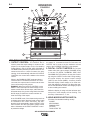
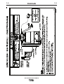
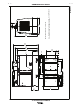
FIGURE b.1
28
27
26
5
6
24
8
14
7
12
13
25
4
9
31
10
3
2
17
11
15
11
21
16
18
19
22
20
16
18
19
20
21
22
11
15
1
1
17
2
3
10
9
31
4
25
13
12
7
14
8
24
6
5
26
27
28
WELDING CONTROLS (Figure b.1)
1. OUTPUT CONTROL- The OUTPUT dial is
used to preset the output voltage or current as displayed on the digital meters for the five welding
modes. When in the CC-STICK, ARC GOUGING or
CV-WIRE modes and when a remote control is connected to the 6-Pin or 14-Pin Connector, the autosensing circuit automatically switches the OUTPUT
CONTROL from control at the welder to the remote
control.
When in the DOWNHILL PIPE mode and when a
remote control is connected to the 6-Pin or 14-Pin
connector, the output control is used to set the maximum current range of the remote.
EXAMPLE: When the OUTPUT CONTROL on the
welder is set to 200 amps the current range on the
remote control will be 40-200 amps, rather than the
full 40-300 amps. Any current range that is less than
the full range provides finer current resolution for
more fine tuning of the output.
In the CV-WIRE mode, if the feeder being used has
a voltage control when the wire feeder control cable
is connected to the 14-Pin Connector, the autosensing circuit automatically makes OUTPUT CONTROL inactive and the wire feeder voltage control
active. Otherwise, the OUTPUT CONTROL is used
to preset the voltage
When in the TOUCH START TIG mode and when
an Amptrol is connected to the 6-Pin Connector, the
OUTPUT dial is used to set the maximum current
range of the CURRENT CONTROL of the Amptrol.
2. DIGITAL OUTPUT METERS- The digital
meters allow the output voltage (CV-WIRE mode)
or current (CC-STICK, DOWNHILL PIPE, ARC
GOUGING and TIG modes) to be set prior to welding using the OUTPUT control dial. During welding,
the meter display the actual output voltage
(VOLTS) and current (AMPS). A memory feature
holds the display of both meters on for seven seconds after welding is stopped. This allows the operator to read the actual current and voltage just prior
to when welding was ceased.
While the display is being held the left-most decimal point in each display will be flashing. The
accuracy of the meters is +/- 3%.
3. WELD MODE SELECTOR SWITCH(Provides five selectable welding modes)
CV-WIRE
ARC GOUGING
DOWNHILL PIPE
CC-STICK
TOUCH START TIG
AIR VANTAGE® 500 KUbOTA
b-4
OPERATION
4. ARC CONTROL- The ARC CONTROL dial is active in
the CV-WIRE, CC-STICK and DOWNHILL PIPE modes,
and has different functions in these modes. This control is
not active in the TIG and ARC GOUGING mode.
CC-STICK mode: In this mode, the ARC CONTROL dial
sets the short circuit current (arc-force) during stick welding
to adjust for a soft or crisp arc. Increasing the dial from –10
(soft) to +10 (crisp) increases the short circuit current and
prevents sticking of the electrode to the plate while welding.
This can also increase spatter. It is recommended that the
ARC CONTROL be set to the minimum number without
electrode sticking. Start with a setting at 0.
DOWNHILL PIPE mode: In this mode, the ARC CONTROL
dial sets the short circuit current (arc-force) during stick
welding to adjust for a soft or a more forceful digging arc
(crisp). Increasing the number from –10 (soft) to +10 (crisp)
increases the short circuit current which results in a more
forceful digging arc. Typically a forceful digging arc is preferred for root and hot passes. A softer arc is preferred for fill
and cap passes where weld puddle control and deposition
("stacking" of iron) are key to fast travel speeds. It is recommended that the ARC CONTROL be set initially at 0.
CV-WIRE mode: In this mode, turning the ARC CONTROL
clock wise from –10 (soft) to +10 (crisp) changes the arc
from soft and washed-in to crisp and narrow. It acts as an
inductance/pinch control. The proper setting depends on the
procedure and operator preference. Start with a setting of 0.
5. WELD OUTPUT TERMINALS WITH FLANGE
NUT- Provides a connection point for the electrode and
work cables.
6. GROUND STUD-
Provides a connection point for
connecting the machine case to earth ground.
7. 14-PIN CONNECTOR- For attaching wire feeder control cables. Includes contactor closure circuit, auto-sensing
remote control circuit, and 42V power. The remote control
circuit operates the same as the 6 Pin Amphenol.
8. 6-PIN CONNECTOR- For attaching optional remote
control equipment. Includes auto-sensing remote control
circuit.
9. WELD TERMINALS CONTROL SWITCH- In the
WELD TERMINALS ON position, the output is electrically
hot all the time. In the REMOTELY CONTROLLED position, the output is controlled by a wire feeder or amptrol
device, and is electrically off until a remote switch is
depressed.
b-4
10. WIRE FEEDER VOLTMETER SWITCH:
Matches the polarity of the wire feeder voltmeter to
the polarity of the electrode.
11. VRD (Voltage Reduction Device) INDICATOR LIGHTS- On the front panel of the AIR VANTAGE® 500 KUBOTA are two indicator lights. A red
light when lit indicates OCV(Open Circuit Voltage) is
equal to or greater than 30V and a green light when
lit indicates OCV(Open Circuit Voltage) is less than
30V.
The VRD “On/Off” switch inside the control panel
must be “On” for the VRD function to be active and
the lights to be enabled. When the machine is first
started with VRD enabled, both lights will illuminate
for 5 seconds.
These lights monitor the OCV(Open Circuit Voltage)
and weld voltage at all times. In the CC-Stick mode
when not welding the green light will illuminate indicating that the VRD has reduced the OCV to less
than 30V. During welding the red light will illuminate
whenever the arc voltage is equal to or greater than
30V. This means that the red and green light may
alternate depending on the weld voltage. This is normal operation.
If the red light remains illuminated when not welding
in the CC-stick mode, the VRD is not functioning
properly. Please refer to your local field service shop
for service.
If the VRD is turned “On” and the lights don’t come
“On”, refer to the trouble shooting section.
TAbLE b.1
VRD INDICATOR LIGHTS
VRD "ON"
VRD "OFF"
Green (OCV Reduced)
Red or Green
(Depends on Weld Voltage) *
Red (OCV Not Reduced)
Weld Terminals On
Red (OCV Not Reduced)
Weld Terminals Remotely Controlled
Gun Trigger Closed
Green (No OCV)
Weld Terminals Remotely Controlled
Gun Trigger Open
No Lights
While
Red or Green
Welding (Depends on Weld Voltage) *
PIPE
OCV
Green (No Output)
While
Not Applicable (No Output)
Welding
ARC GOUGING OCV
Green (No Output)
While
Not Applicable (No Output)
Welding
TIG
OCV
Green (Process is Low Voltage)
While
Green (Process is Low Voltage)
Welding
MODE
CC-STICK OCV
While
Welding
CV-WIRE OCV
* It is normal for the lights to alternate between colors while welding.
AIR VANTAGE® 500 KUbOTA
b-5
OPERATION
b-5
ENGINE CONTROLS:
21. ENGINE PROTECTION LIGHT- A warning indi-
12. RUN/STOP SWITCH -
cator light for Low Oil Pressure and/or Coolant Over
Temperature.The light is off when the systems are functioning properly. The light will come on and the engine
will shutdown when there is Low Oil Pressure and/or
the Coolant is Over Temperature.
-RUN position energizes the engine prior to starting.
STOP position stops the engine. The oil pressure interlock switch prevents battery drain if the switch is left in
the RUN position and the engine is not operating.
13. GLOW PLUG PUSH bUTTON • When pushed activates the glow plugs. Glow plug
should not be activated for more than 20 seconds continuously.
14. START PUSH bUTTON - Energizes the starter
motor to crank the engine.
15. IDLER SWITCH- Has two positions as follows:
1) In the HIGH position, the engine runs at the high idle
speed controlled by the engine governor.
2) In the AUTO position, the idler operates as follows:
• When switched from HIGH to AUTO or after starting
the engine, the engine will operate at full speed for
approximately 12 seconds and then go to low idle
speed.
• When the electrode touches the work or power is
drawn for lights or tools (approximately 100 Watts minimum), the engine accelerates and operates at full
speed.
• When welding ceases or the AC power load is turned
off, a fixed time delay of approximately 12 seconds
starts. If the welding or AC power load is not restarted
before the end of the time delay, the idler reduces the
engine speed to low idle speed.
• The engine will automatically return to high idle speed
when there is welding load or AC power load reapplied.
Note: The light remains off when the RUN-STOP switch
is in the "ON" position prior to starting the
engine.However if the engine is not started within
60 seconds the light will come on. When this hap
pens the RUN-STOP switch must be returned to
the "OFF" position to reset the engine protection
system and light.
22. bATTERY CHARGING LIGHT- A warning indicator light for Low/No battery charge. The light is off when
the systems are functioning properly. The light will
come on if there is a Low/No battery condition but the
machine will continue to run.
Note: The light may or may not come on when the
RUN-STOP switch is in the "ON" position. It will
come on during cranking and stay on until the
engine starts. After starting the engine the light will
go off unless a Low/No battery charge condition
exists.
16. ENGINE HOUR METER- Displays the total time
that the engine has been running. This meter is useful
for scheduling prescribed maintenance.
17. CIRCUIT bREAKER- For protection of Battery
Charging Circuit.
18. ELECTRIC FUEL GAUGE- The electric fuel
gauge gives accurate and reliable indication as to how
much fuel is in the fuel tank.
19. COOLANT TEMPERATURE GAUGE- A indicator of engine coolant temperature.
20. OIL PRESSURE GAUGE- A indicator of engine
Oil Pressure.
AIR VANTAGE® 500 KUbOTA
b-6
OPERATION
b-6
AIR COMPRESSOR CONTROLS (24
THRU 26)
bATTERY JUMP START TERMINAL
(27-28)
24. COMPRESSOR ON/OFF SWITCH
27. POSITIVE bATTERY JUMP START
TERMINAL.
Turns compressor on and off (standby) by opening
and closing the compressor inlet valve.
25. COMPRESSOR PROTECTION LIGHT
28. NEGATIVE bATTERY JUMP START
TERMINAL.
The yellow compressor protection light remains off
with proper compressor oil temperatures. If the lights
turn on, the compressor protection system will close
the compressor inlet valve and put the system in
standby mode until the temperature reaches allowable
limits. Check for proper compressor oil level.
12V battery jump start feature is standard. Covered
output studs for convenient access, and protection
against accidental impact. Can be used to jump-start
a utility truck with up to 800 cold cranking amps. Can
also be used to junp-start the AIR VANTAGE® 500
KUBOTA Cummins.
26. AIR DISCHARGE VALVE
29. bATTERY DISCONNECT SWITCH
Controls flow of compressed air. A 3/4” NPT (National
Pipe Thread) fitting is provided.
Battery disconnect switch provides lockout/tagout
capability. Switch is conveniently located inside the
engine compartment. (SEE FIGURE B.2)
30. AIR CLEANER SERVICE INDICATOR
FIGURE b.2
29
Air cleaner service indicator provides a Go/No-Go
visual indication of useful filter service life. Also located inside the engine compartment. (SEE FIGURE B.2)
31. CIRCUIT bREAKERS
These circuit breakers provide separate overload current protection for each 120V circuit at the 240V single
phase receptacle, each 120V single phase receptacle,
the 240V three phase receptacle, the 120VAC in the
14-Pin connector, the 42VAC in the 14-Pin connector
and battery circuit overload protection.
STARTING THE ENGINE
1. Remove all plugs connected to the AC power receptacles.
2. Set IDLER switch to AUTO.
30
3. Press Glow Plug Button and hold 15 to 20 seconds.
4. Set the RUN/STOP switch to RUN.
5. Press START button until the engine starts or for up to 10
seconds. Continue to hold the glow plug button for up to
an additional 10 seconds.
6. Release the engine START button immediately when the
engine starts.
7. The engine will run at high idle speed for approximately
12 seconds and then drop to low idle speed. Allow the
engine to warm up at low idle for several minutes before
applying a load and/or switching to high idle. Allow a
longer warm up time in cold weather.
AIR VANTAGE® 500 KUbOTA
b-7
OPERATION
NOTE: If the unit fails to start turn Run/Stop switch
to off and repeat step 3 through step 7 after
waiting 30 seconds.
CAUTION
• Do not allow the starter motor to run continuously
for more than 20 seconds.
• Do not push the START button while the engine
is running because this can damage the ring
gear and/or the starter motor.
• IF the Engine Protection or battery Charging
Lights do “not” turn off shortly after starting the
engine shut off the engine immediately and
determine the cause.
--------------------------------------------------------------------------------
NOTE: When starting for the first time, or after and
extended period of time of not operating, it will take
longer than normal to start because the fuel pump has
to fill the fuel system. For best results, bleed the fuel
system as indicated in Maintenance Section of this
manual.
STOPPING THE ENGINE
Remove all welding and auxiliary power loads and
allow the engine to run at low idle speed for a few
minutes to cool the engine.
STOP the engine by placing the RUN-STOP switch in
the STOP position.
NOTE: A fuel shut off valve is located on the fuel pre-filter.
TAbLE b.2
TYPICAL AIR VANTAGE® 500 KUbOTA FUEL CONSUMPTION
b-7
WELDER OPERATION
DUTY CYCLE
Duty Cycle is the percentage of time the load is being
applied in a 10 minute period. For example a 60% duty
cycle, represents 6 minutes of load and 4 minutes of no
load in a 10 minute period.
ELECTRODE INFORMATION
For any electrode the procedures should be kept within the rating of the machine. For information on electrodes and their proper application see (www.lincolnelectric.com) or the appropriate Lincoln publication.
The AIR VANTAGE® 500 KUBOTA can be used with a
broad range of DC stick electrodes. The MODE switch
provides two stick welding settings as follows:
CONSTANT CURRENT (CC-STICK)
WELDING
The CC-STICK position of the MODE switch is designed
for horizontal and vertical-up welding with all types of
electrodes, especially low hydrogen. The OUTPUT CONTROL dial adjusts the full output range for stick welding.
The ARC CONTROL dial sets the short circuit current (arcforce) during stick welding to adjust for a soft or crisp arc.
Increasing the number from -10(soft) to +10(crisp) increases the short circuit current and prevents sticking of the
electrode to the plate while welding. This can also increase
spatter. It is recommended that the ARC CONTROL be set
to the minimum number without electrode sticking. Start
with the dial set at 0.
V3600-T 58HP(43.2kw) @
Running Time for
NOTE: Due to the low OCV with the VRD on, a very
1850 RPM Gal./Hr (Liters/Hr) 25Gal.(94.6L) / hours
Low Idle - No Load
1425 R.P.M.
Low Idle - 1425 R.P.M.
Air Compressor
40 CFM @ 100PSI
High Idle - No Load
1850 R.P.M.
DC CC Weld Output
500 Amps @ 40Volts
Auxiliary Power 12,000 VA
Auxiliary Power 20,000 VA
Air Compressor
60 CFM @ 100 PSI
.69(2.6)
36.23
.90(3.4)
27.78
1.04(3.9)
24.04
2.54(9.6)
1.71(6.5)
2.28(8.6)
1.42(5.4)
9.84
14.62
10.96
17.60
3.09(11.7)
8.09
2.19(8.3)
11.42
slight delay during striking of the electrodes may
occur. Due to the requirement of the resistance in the
circuit to be low for a VRD to operate, a good metalto-metal contact must be made between the metal
core of the electrode and the job. A poor connection
anywhere in the welding output circuit may limit the
operation of the VRD. This includes a good connection of the work clamp to the job. The work clamp
should be connected as close as practical to where
the welding will be performed.
Air Compressor
60 CFM @ 100 PSI
and DC, CC Weld
Output 500 Amps
@40 Volts
Air Compressor
60 CFM @ 100 PSI
and Auxiliary Power
12,000
A. For New Electrodes
NOTE: This data is for reference only. Fuel consumption is
approximate and can be influenced by many factors, including
engine maintenance, environmental conditions and fuel quality.
AIR VANTAGE® 500 KUbOTA
b-8
OPERATION
E6010 - Touch, Lift to Start the Arc
E7018, E7024 - Touch, Rock Back and Forth in Joint,
Lift .
Once the arc is started, normal welding technique for
the application is then used.
b. For Re-Striking Electrodes
Some electrodes form a cone at the end of the electrode after the welding arc has been broken, particularly iron powder and low hydrogen electrodes. This
cone will need to be broken off in order to have the
metal core of the electrode make contact.
E6010 - Push, Twist in Joint, Lift
E7018, E7024 - Push, Rock Back and Forth in Joint,
Lift.
Once the arc is started, normal welding technique for
the application is then used.
For other electrodes the above techniques should be
tried first and varied as needed to suit operator preference. The goal for successful starting is good metal to
metal contact.
For indicator light operation, see table B.1.
DOWNHILL PIPE WELDING
This slope controlled setting is intended for "out-of-position" and "down hill" pipe welding where the operator
would like to control the current level by changing the arc
length.
The OUTPUT CONTROL dial adjusts the full output
range for pipe welding.
The ARC CONTROL dial sets the short circuit current
(arc-force) during stick welding to adjust for a soft or
more forceful digging arc (crisp). Increasing the number
from -10(soft) to +10(crisp) increases the short circuit
current which results in a more forceful digging arc.
Typically a forceful digging arc is preferred for root and
hot passes. A softer arc is preferred for fill and cap passes where weld puddle control and deposition (“stacking”
of iron) are key to fast travel speeds. This can also
increase spatter.
It is recommended that the ARC CONTROL be set to the
minimum number without electrode sticking. Start with
the dial set at 0.
NOTE: With the VRD switch in the “ON” position there is
no output in the DOWNHILL PIPE mode. For indicator
light operation, see table B.1.
b-8
TIG WELDING
The TOUCH START TIG setting of the MODE switch is
for DC TIG (Tungsten Inert Gas) welding. To initiate a
weld, the OUTPUT CONTROL dial is first set to the
desired current and the tungsten is touched to the work.
During the time the tungsten is touching the work there is
very little voltage or current and, in general, no tungsten
contamination. Then, the tungsten is gently lifted off the
work in a rocking motion, which establishes the arc.
When in the TOUCH START TIG mode and when a
Amptrol is connected to the 6-Pin connector the OUTPUT CONTROL dial is used to set the maximum current range of the current control of the Amptrol.
The ARC CONTROL is not active in the TIG mode. To
STOP a weld, simply pull the TIG torch away from the
work.
When the arc voltage reaches approximately 30 Volts
the arc will go out and the machine will reset the current to the Touch Start level.
To reinitiate the arc, retouch the tungsten to the work
and lift. Alternatively, the weld can be stopped by
releasing the Amptrol or arc start switch.
The AIR VANTAGE® 500 KUBOTA can be used in a
wide variety of DC TIG welding applications. In general the ‘Touch Start’ feature allows contamination free
starting without the use of a Hi-frequency unit. If
desired, the K930-2 TIG Module can be used with the
AIR VANTAGE® 500 KUBOTA . The settings are for
reference.
AIR VANTAGE® 500 KUBOTA settings when using
the K930-2 TIG Module with an Amptrol or Arc Start
Switch:
• Set the MODE Switch to the TOUCH START TIG
setting.
• Set the "IDLER" Switch to the "AUTO" position.
• Set the "WELDING TERMINALS" switch to the
"REMOTELY CONTROLLED" position.
This will keep the "Solid State" contactor open and provide a
"cold" electrode until the Amptrol or Arc Start Switch is pressed.
When using the TIG Module, the OUTPUT CONTROL on the
AIR VANTAGE® 500 KUBOTA is used to set the maximum
range of the CURRENT CONTROL on the TIG Module or an
Amptrol if connected to the TIG Module.
NOTE: The TIG process is to receive a low voltage welding
process. There is no difference in operation with the
VRD “On” or “Off” for this mode. For indicator light operation, see table B.1.
AIR VANTAGE® 500 KUbOTA
b-9
b-9
OPERATION
WIRE WELDING-CV
Connect a wire feeder to the AIR VANTAGE® 500 KUBOTA
according to the instructions in INSTALLATION INSTRUCTIONS Section.
The AIR VANTAGE® 500 KUBOTA in the CV-WIRE mode,
permits it to be used with a broad range of flux cored wire
(Innershield and Outershield) electrodes and solid wires for
MIG welding (gas metal arc welding). Welding can be finely
tuned using the ARC CONTROL. Turning the ARC CONTROL clockwise from –10 (soft) to +10 (crisp) changes the
arc from soft and washed-in to crisp and narrow. It acts as
an inductance/pinch control. The proper setting depends on
the procedure and operator preference. Start with the dial
set at 0.
NOTE: In the CV-Mode with VRD “On”, the OCV(Open
Circuit Voltage) is not reduced. For indicator light
operation, see table B.1.
ARC GOUGING
The AIR VANTAGE® 500 KUBOTA can be used for arc
gouging.
For optimal performance, set the MODE switch to ARC
GOUGING. Set the OUTPUT CONTROL knob to adjust output current to the desired level for the gouging electrode
being used according to the ratings in the following Table
B.4
The ARC CONTROL is not active in the ARC GOUGING
Mode. The ARC CONTROL is automatically set to maximum
when the ARC GOUGING mode is selected which provides
the best ARC GOUGING performance.
NOTE: With the VRD switch in the “ON” position there is no
output in the Arc Gouging Mode. For indicator light operation, see table B.1.
TAbLE b.4
Carbon Diameter
Current Range (DC, electrode
positive)
1/8"(3.2mm)
30-60 Amps
5/32"(4.0mm)
90-150 Amps
3/16"9(4.8mm)
200-250 Amps
1/4"(6.4mm)
300-400 Amps
3/8"(10.0mm)
450-575 Amps*
NOTE: If desired the CV mode can be used for Arc Gouging.
* Maximum current setting is limited to the AIR VANTAGE® 500
KUBOTA maximum of 575 Amps.
Table b.3 TYPICAL CURRENT RANGES (1) FOR TUNGSTEN ELECTRODES (2)
Tungsten
Electrode
Diameter
mm (in)
DCEN (-)
DCEP (+)
1%, 2%
Thoriated
Tungsten
1%, 2%
Thoriated
Tungsten
Approximate Argon Gas Flow Rate
l/min (c.f.m.)
Aluminium
Stainless Steel
TIG TORCH
Nozzle
Size (4), (5)
#4, #5, #6
.25 (0.010)
2-15
(3)
2-4 (3-8)
2-4 (3-8)
.50 (0.020)
5-20
(3)
3-5 (5-10)
3-5 (5-10)
1.0 (0.040)
15-80
(3)
3-5 (5-10)
3-5 (5-10)
1.6 (1/16)
70-150
10-20
3-5 (5-10)
4-6 (9-13)
#5, #6
2.4 (3/32)
3.2 (1/8)
150-250
250-400
15-30
25-40
6-8 (13-17)
7-11 (15-23)
5-7 (11-15)
5-7 (11-15)
#6, #7, #8
4.0 (5/32)
4.8 (3/16)
400-500
500-750
40-55
55-80
10-12 (21-25)
11-13 (23-27)
6-8 (13-17)
8-10 (18-22)
#8, #10
6.4 (1/4)
750-1000
80-125
13-15 (28-32)
11-13 (23-27)
(1)
When used with argon gas. The current ranges shown must be reduced when using argon/helium or pure helium shielding gases.
(2)
Tungsten electrodes are classified as follows by the American Welding Society (AWS):
Pure
EWP
1% Thoriated
EWTh-1
2% Thoriated
EWTh-2
Though not yet recognized by the AWS, Ceriated Tungsten is now widely accepted as a substitute for 2% Thoriated Tungsten in AC and DC applications.
(3)
DCEP is not commonly used in these sizes.
(4)
TIG torch nozzle “sizes” are in multiples of 1/16ths of an inch:
#4=
#5=
#6=
#7=
#8=
#10 =
(5)
1/4 in.
5/16 in.
3/8 in.
7/16 in.
1/2 in.
5/8 in.
6 mm
8 mm
10 mm
11 mm
12.5 mm
16 mm
TIG torch nozzles are typically made from alumina ceramic. Special applications may require lava nozzles, which are less prone to breakage, but cannot withstand high temperatures and high duty cycles.
AIR VANTAGE® 500 KUbOTA
b-10
b-10
OPERATION
PARALLELING
When paralleling machines in order to combine their
outputs, all units must be operated in the CC-STICK
mode only at the same output settings. To achieve
this, turn the WELD MODE switch to the CC-STICK
position. Operation in other modes may produce erratic outputs, and large output imbalances between the
units.
AUXILIARY POWER OPERATION
If a GFCI receptacle is tripped, See the MAINTENANCE section for detailed information on testing and
resetting the GFCI receptacle.
Start the engine and set the IDLER control switch to
the desired operating mode. Full power is available
regardless of the welding control settings, if no welding current is being drawn.
The auxiliary power of the AIR VANTAGE® 500 KUBOTA consists of two 20 Amp-120VAC single phase (520R) GFCI duplex receptacles, one 50 Amp120/240VAC single phase (14-50R) receptacle and
one 50 Amp 240VAC three phase (15-50R) receptacle. The 120/240VAC receptacle can be split for single
phase 120 VAC operation.
The auxiliary power capacity is 12,000 watts of 60 Hz,
single phase power or 20,000 watts of 60Hz, three
phase power. The auxiliary power capacity rating in
watts is equivalent to volt-amperes at unity power factor.
The maximum permissible current of the 240 VAC
output is 50 A. The 240 VAC single phase output can
be split to provide two separate 120 VAC outputs with
a maximum permissible current of 50 A per output to
two separate 120 VAC branch circuits. Output voltage
is within ± 10% at all loads up to rated capacity.
NOTE: The two 120V GFCI modules, receptacles and
the two 120V circuits of the 120/240V receptacle are
connected to different phases and cannot be paralleled.
The auxiliary power receptacles should only be used
with three wire grounded type plugs or approved double insulated tools with two wire plugs.
The current rating of any plug used with the system
must be at least equal to the current capacity of the
associated receptacle.
SIMULTANEOUS WELDING AND AUXILIARY POWER LOADS
It must be noted that the above auxiliary power ratings
are with no welding load. Simultaneous welding and
power loads are specified in table B.5. The permissible currents shown assume that current is being
drawn from either the 120 VAC or 240 VAC supply
(not both at the same time).
TAbLE b.5 AIR VANTAGE® 500 KUbOTA SIMULTANEOUS WELDING AND POWER LOADS
WELD
1 PHASE
3 PHASE
bOTH 1 AND 3 PHASE
AMPS
WATTS
AMPS
WATTS
AMPS
WATTS
AMPS
0
12,000
50
20,000
50
-----50
100
12,000
50
17,800
43
-----50
PLUS 12,000
OR
200
50
14,000
34
-----50
OR
250
12,000
50
12,000
29
12,000
-----300
10,000
42
10,000
24
10,000
-----400
5,600
23
5,600
13
5,600
-----500
0
0
0
0
0
0
TAbLE b.6
AIR VANTAGE® 500 KUbOTA Extension Cord Length Recommendations
(Use the shortest length extension cord possible sized per the following table.)
Current Voltage Load
(Amps) (Volts) (Watts)
15
120
1800
3600
15
240
20
120
2400
20
240
4800
25
240
6000
240
7200
30
38
240
9000
50
240
12000
14 AWG
30
(9)
60
(18)
Maximum Allowable Cord Length in ft. (m) for Conductor Size
12 AWG
10 AWG
8 AWG
6 AWG
40
(12)
75
(23)
125
(38)
175
(53)
75
(23)
150
(46)
225
(69)
350
(107)
30
(9)
50
(15)
88
(27)
138
(42)
60
(18)
100
(30)
175
(53)
275
(84)
90
(27)
150
(46)
225
(69)
75
(23)
120
(37)
175
(53)
100
(30)
150
(46)
125
(38)
Conductor size is based on maximum 2.0% voltage drop.
AIR VANTAGE® 500 KUbOTA
4 AWG
300
(91)
600
(183)
(69)
225
450
(137)
(76)
250
300
(91)
250
(76)
200
(61)
C-1
ACCESSORIES
FIELD INSTALLED OPTIONS /
ACCESSORIES are available at
www.lincolnelectric.com.
Follow these steps:
1. Go to www.lincolnelectric.com
2. At the top of the screen in the Search field type
E6.217 click on Search Icon.
3. On the results screen click on Engine Driven
Welders: AIR VANTAGE® 500
4. On this results screen which shows AIR VANTAGE®
500 sales literature document, scroll down to the
beginning of the RECOMMENDED OPTIONS
page.
AIR VANTAGE® 500 KUbOTA
C-1
D-1
D-1
MAINTENANCE
VMAC™
SAFETY PRECAUTIONS
(VEHICLE MOUNTED AIR COMPRESSORS)
WARNING
WWW.VMAC.CA
• Have qualified personnel do all maintenance
and troubleshooting work.
• Turn the engine off before working inside the
machine or servicing the engine.
• Remove guards only when necessary to
perform maintenance and replace them when
the maintenance requiring their removal is
complete. If guards are missing from the
machine, obtain replacements from a Lincoln
Distributor. (See Operating Manual Parts List.)
1333 Kipp Road
Nanamino
British Columbia
Canada, V9X1R3
Telephone: (250) 740-3200
Facsimile: (250) 740-3201
Toll Free: 800-738-8622
ENGINE MAINTENANCE
Read the Safety Precautions in the front of this
manual and in the Engine Owner’s Manual before
working on this machine.
ROUTINE AND PERIODIC MAINTENANCE
Refer to the “Periodic Checks” section of the Engine
Operator’s Manual for the recommended maintenance
schedule of the following:
a) Engine Oil and Filter
b) Air Cleaner
c) Fuel Filter - and Delivery System
d) Alternator Belt
e) Battery
f ) Cooling System
Refer to Table D.1 at the end of this section for various engine maintenance components.
DAILY
AIR FILTER
• Check the Engine and Compressor oil levels .
• Refill the fuel tank to minimize moisture condensation in the tank.
• Check water separator for water and drain if necessary.
• Check coolant level.
• Only VMAC certified and approved synthetic oil
• Excessive air filter restriction will result in
Keep all equipment safety guards, covers, and
devices in position and in good repair. Keep
hands, hair, clothing, and tools away from the
gears, fans, and all other moving parts when
starting, operating, or repairing the equipment.
--------------------------------------------------------------------------------
CAUTION
reduced engine life.
• Never use gasoline or low flash point solvents
WARNING
WARNING
be
used.
Shut
down
the
MUST
Welder/Compressor for 3 minutes, open the
pressure supply valve to ensure the system is
depressurized prior to removing the compressor oil level dipstick.
------------------------------------------------------------------------
for cleaning the air cleaner element. A fire or
explosion could result.
• Never run the engine without the air cleaner.
WEEKLY
Rapid engine wear will result from contaminants,
such as dust and dirt being drawn into the
engine.
-----------------------------------------------------------------------The diesel engine is equipped with a dry type air filter.
Never apply oil to it. Service the air cleaner as follows:
Blow out the machine with low pressure air periodically. In particularly dirty locations, this may be required
once a week.
COMPRESSOR MAINTENANCE
Refer to the “Routine Maintenance” section of the
compressor owner’s manual for the recommended
maintenance schedule of the following:
a. Compressor oil and filter.
b. Compressor air filter.
c. Compressor coalescing filter.
CAUTION
Replace the element as indicated by the service indicator. (See Service Instructions and Installation Tips
for Engine Air Filter.)
AIR VANTAGE® 500 KUbOTA
D-2
D-2
MAINTENANCE
Service Instructions
Single- and Two-Stage Engine Air Cleaners
Inspect the New Filter for Damage
Remove the Filter
Rotate the
filter while
pulling
straight out.
Unfasten or unlatch the
service cover. Because
the filter fits tightly over the
outlet tube to create the critical seal, there will
be some initial resistance, similar to breaking
the seal on a jar. Gently move the end of the filter
back and forth to break the seal then rotate while
pulling straight out. Avoid knocking the filter
against the housing.
If your air cleaner has a safety filter, replace it every third primary
filter change. Remove the safety filter as you would the primary
filter. Make sure you cover the air cleaner outlet tube to avoid any
unfiltered contaminant dropping into the engine.
Clean Both Surfaces of the Outlet Tube
and Check the Vacuator™ Valve
Use a clean cloth to wipe the filter sealing surface and the inside of
the outlet tube. Contaminant on the sealing surface could hinder an
effective seal and cause leakage. Make sure that all contaminant is
removed before the new filter is inserted. Dirt accidently transferred
to the inside of the outlet tube will reach the engine and cause
wear. Engine manufacturers say that it takes only a few grams of
dirt to "dust" an engine! Be careful not to damage the sealing area
on the tube.
Wipe both sides
of the outlet
tube clean.
Outer edge of the
outlet tube
Inspect the new filter carefully, paying attention to
the inside of the open end, which is the
sealing area. NEVER install a damaged
filter. A new Donaldson radial seal
filter may have a dry lubricant on the
seal to aid installation.
Insert the New Radial Seal Filter Properly
If you're servicing the safety filter, this should be seated into
position before installing the primary filter.
Insert the new filter carefully. Seat
the filter by hand, making certain it is
completely into the air cleaner housing
before securing the cover in place.
The critical sealing area will stretch
slightly, adjust itself and distribute the sealing pressure evenly. To
complete a tight seal, apply pressure by hand at the outer rim of
the filter, not the flexible center. (Avoid pushing on the center of the
urethane end cap.) No cover pressure is required to hold the seal.
NEVER use the service cover to push the filter into place! Using the
cover to push the filter in could cause damage to the housing, cover
fasteners and will void the warranty.
If the service cover hits the filter before it is fully in place, remove
the cover and push the filter (by hand) further into the air cleaner
and try again. The cover should go on with no extra force.
Once the filter is in place, secure the service cover.
Inner edge of the
outlet tube
If your air cleaner is equipped with a Vacuator Valve
Visually check and physically squeeze to make sure the
valve is flexible and not inverted, damaged or plugged.
Caution
NEVER use the service cover to
push the filter into place! Using
the cover to push the filter in could
cause damage to the housing, cover
fasteners and will void the warranty.
Inspect the Old
Filter for Leak Clues
Visually inspect the old filter for any signs
of leaks. A streak of dust on the clean side
of the filter is a telltale sign. Remove any
cause of leaks before installing new filter.
Check Connectors for Tight Fit
Make sure that all mounting bands, clamps, bolts, and connections
in the entire air cleaner system are tight. Check for holes in piping
and repair if needed. Any leaks in your intake piping will send dust
directly to the engine!
AIR VANTAGE® 500 KUbOTA
D-3
D-3
MAINTENANCE
ENGINE OIL CHANGE
OIL FILTER CHANGE
Drain the engine oil while the engine is warm to assure
rapid and complete draining. It is recommended that
each time the oil is changed the oil filter be changed as
well.
• Drain the oil.
• Be sure the unit is off. Disconnect the negative battery cable to ensure safety.
• Locate oil drain hose and valve in bottom of base
and pull through the hole in the battery access panel
on the welder.
• Open oil drain valve by lifting up spring loaded lever
and rotate 90° counterclockwise. Pull to open and
drain the oil into a suitable container for disposal.
• Close the drain valve by rotating lever 90° clockwise.
• Re-fill the crankcase to the upper limit mark on the
dipstick with the recommended oil (see engine operation manual OR engine service items decal OR
below). Replace and tighten the oil filler cap securely.
• Push oil drain hose and valve back into unit, re-connect negative battery cable, and close doors and
engine top cover before restarting unit.Wash your
hands with soap and water after handling used motor
oil. Please dispose of used motor oil in a manner that
is compatible with the environment. We suggest you
take it in a sealed container to your local service station or recycling center for reclamation. DO NOT
throw it in the trash; pour it on the ground or down a
drain.
Use motor oil designed for diesel engines that meets
requirements for API service classification
CC/CD/CE/CF/CF-4/CG-4 or CH-4.
ACEA E1/E2/E3. Always check the API service label
on the oil container to be sure it includes the letters
indicated. (Note: An S-grade oil must not be used in a
diesel engine or damage may result. It IS permissible
to use an oil that meets S and C grade service classifications.)
SAE 10W30 is recommended for general, all temperature use, 5F to 104F (-15C to 40C).
• Remove the oil filter with an oil filter wrench and
drain the oil into a suitable container. Discard the
used filter. Note: Care should be taken during filter
removal to not disrupt or damage in any way the fuel
lines.
• Clean the filter mounting base and coat the gasket
of the new filter with clean engine oil.
• Screw the new filter on by hand until the gasket contacts the mounting base. Using an oil filter wrench,
tighten the filter an additional 1/2 to 7/8 of a turn.
• Refill the crankcase with the specified amount of the
recommended engine oil. Reinstall the oil filler cap
and tighten securely.
• Start the engine and check for oil filter leaks.
• Stop the engine and check the oil level. If necessary, add oil to the upper limit mark on the dipstick.
WARNING
• Never use gasoline or low flash point solvents
for cleaning the air cleaner element. A fire or
explosion could result.
CAUTION
• Never run the engine without the air cleaner.
Rapid engine wear will result from contaminants,
such as dust and dirt being drawn into the
engine.
------------------------------------------------------------------------
AIR CLEANER
The diesel engine is equipped with a dry type air filter.
Never apply oil to it. Service the air cleaner as follows:
Replace the element every 500 hours of operation.
Under dusty conditions, replace sooner.
See engine owner’s manual for more specific information on oil viscosity recommendations.
AIR VANTAGE® 500 KUbOTA
D-4
D-4
MAINTENANCE
FUEL: Diesel Fuel Only - Low Sulphur Fuel
COOLING SYSTEM
or Ultra Low Sulphur Fuel in U.S.A. and
CANADA only.
WARNING
HOT COOLANT can burn skin.
• Do not remove cap if radiator is
hot.
-----------------------------------------------------------------------Check the coolant level by observing the level in the
radiator and recovery bottle. Add 50/50 antifreeze /
water solution if the level is close to or below the
"LOW" mark. Do not fill above the "FULL" mark.
Remove radiator cap and add coolant to radiator. Fill
up to the top of the tube in the radiator filler neck
which includes a connecting hose coming from the
thermostat housing.
To drain the coolant, open the valve at the bottom of
the radiator. Open the radiator cap to allow complete
drainage. (Tighten the valve and refill with a 50/50
antifreeze/water solution.) Use an automotive grade
(low silicate) ethylene glycol antifreeze. The cooling
system capacity is 2.6gal. (9.8L). Squeeze upper and
lower radiator hoses while filling to bleed air from system coolant. Replace and tighten the radiator cap.
CAUTION
Always premix the antifreeze and clean tap water
before adding to the radiator. It is very important
that a precise 50/50 solution be used with this
engine year round. This gives proper cooling during hot weather and freezing protection to -34° F (37° C).
Cooling solution exceeding 50% ethylene glycol
can result in engine overheating and damage to
the engine. Coolant solution must be premixed
before adding to radiator.
------------------------------------------------------------------------
At the end of each day’s use, refill the fuel tank to minimize moisture condensation and dirt contamination in
the fuel line. Do not overfill; leave room for the fuel to
expand.
Use only fresh No. 2D diesel fuel, the use of No. 1D
diesel fuel is recommended in place of No. 2D at temperatures below 23°F (-5°C). Do not use kerosene.
See the Engine Operator's Manual for instructions on
replacing the fuel filter.
bLEEDING THE FUEL SYSTEM
You may need to bleed air from the fuel system if the
fuel filter or fuel lines have been detached, the fuel
tank has been ran empty or after periods of long storage. It is recommended that the fuel shutoff valve be
closed during periods of non-use.
WARNING
To avoid personal injury, do not bleed a hot
engine. This could cause fuel to spill onto a hot
exhaust manifold, creating a danger of fire.
-----------------------------------------------------------------------bleed the fuel system as follows:
1.
2.
3.
4.
Fill the fuel tank with fuel.
Open the fuel shut off valve.
Loosen bleed fitting on the fuel injection pump.
Be sure the “Run/Stop” switch is in the OFF position. Crank engine for 20 second burst until the
engine starts. Close bleed fitting. Start the engine
and let it run for 5 to 10 minutes to work the air out
of the lines.
5. Follow normal STARTING procedures until engine
starts.
Periodically remove the dirt from the radiator fins.
Periodically check the fan belt and radiator hoses.
Replace if signs of deterioration are found.
FUEL FILTER
TIGHTENING THE FAN bELT
2. Replace the fuel filter if it is found with excessive
water accumulation or sediment. Empty fuel pre-filter.
If the fan belt is loose, the engine can overheat and
the battery lose its charge. Check tightness by pressing on the belt midway between the pulleys. It should
deflect about .25 in.(6.4 mm) under a load of 20 lbs.(9
Kg).
1. Check the fuel filter and fuel pre-filter for water
accumulation or sediment.
AIR VANTAGE® 500 KUbOTA
D-5
OVERSPEED IS HAzARDOUS
The maximum allowable high idle speed for this
machine is 1850 RPM, no load. Do NOT tamper
with governor components or setting or make any
other adjustments to increase the maximum
speed. Severe personal injury and damage to the
machine can result if operated at speeds above
maximum.
ENGINE ADJUSTMENT
Adjustments to the engine are to be made only by a
Lincoln Service Center or an authorized Field Service
Shop.
Be sure the battery vent plugs (if equipped) are tight
so that none of the solution enters the cells.
After cleaning, flush the outside of the battery, the battery compartment, and surrounding areas with clear
water. Coat the battery terminals lightly with petroleum
jelly or a non-conductive grease to retard corrosion.
Keep the battery clean and dry. Moisture accumulation on the battery can lead to more rapid discharge
and early battery failure.
CHECKING THE ELECTROLYTE LEVEL
If battery cells are low, fill them to the neck of the filler
hole with distilled water and recharge. If one cell is
low, check for leaks.
bATTERY MAINTENANCE
To access the battery, remove the battery tray from
the front of the machine with 3/8” nut driver or flat
head screw driver. Pull the tray out of machine far
enough to disconnect the negative and then positive
battery cables. The tray can then be tilted and lifted to
remove the entire tray and battery from the machine
for easy service.
WARNING
GASES FROM bATTERY can explode.
l
Keep sparks, flame and cigarettes
away from battery.
l
D-5
MAINTENANCE
To prevent EXPLOSION when:
l INSTALLING A NEW bATTERY —
disconnect negative cable from old
battery first and connect to new
battery last.
CONNECTING A bATTERY CHARGER —
remove battery from welder by disconnecting
negative cable first, then positive cable and
battery clamp. When reinstalling, connect
negative cable last. Keep well ventilated.
USING A bOOSTER — connect
positive lead to battery first then
connect negative lead to negative
battery lead at engine foot.
bATTERY ACID can burn eyes and skin.
l Wear gloves and eye protection and be careful
when working near battery.
l Follow instructions printed on battery.
l
CLEANING THE bATTERY
Keep the battery clean by wiping it with a damp cloth
when dirty. If the terminals appear corroded, disconnect the battery cables and wash the terminals with an
ammonia solution or a solution of 1/4 pound
(0.1113kg) of baking soda and 1 quart (0.9461L) of
water.
CHARGING THE bATTERY
When you charge, jump, replace, or otherwise connect battery cables to the battery, be sure the polarity
is correct. Improper polarity can damage the charging
circuit. The AIR VANTAGE® 500 KUBOTA positive
(+) battery terminal has a red terminal cover.
If you need to charge the battery with an external
charger, disconnect the negative cable first, then the
positive cable before you attach the charger leads.
After the battery is charged, reconnect the positive
battery cable first and the negative cable last. Failure
to do so can result in damage to the internal charger
components.
Follow the instructions of the battery charger manufacturer for proper charger settings and charging time.
SERVICING MUFFLER WITH INTERNAL SPARK ARRESTOR
Clean every 100 hours. Remove screw plug on muffler body and either vacuum out OR shake out until
clean.
WARNING
• MUFFLER MAY bE HOT
• ALLOW ENGINE TO COOL bEFORE INSTALLING
THE SPARK ARRESTER!
• DO NOT OPERATE ENGINE WHILE INSTALLING
THE SPARK ARRESTOR!
------------------------------------------------------------------------
AIR VANTAGE® 500 KUbOTA
D-6
D-6
MAINTENANCE
WELDER / GENERATOR
MAINTENANCE
GFCI MODULE TESTING AND RESETTING
PROCEDURE
STORAGE: Store in clean, dry protected areas.
The GFCI module should be properly tested at least
once every month or whenever it is tripped. To properly
test and reset the GFCI module:
CLEANING: Blow out the generator and controls periodically with low pressure air. Do this at least once a
week in particularly dirty areas.
bRUSH REMOVAL AND REPLACEMENT: It’s normal for the brushes and slip rings to wear and darken
slightly. Inspect the brushes when a generator overhaul is necessary.
CAUTION
• Do not attempt to polish slip rings while the
engine is running.
WARNING
• Service and Repair should only be performed by
Lincoln Electric Factory Trained Personnel.
Unauthorized repairs performed on this equipment may result in danger to the technician and
machine operator and will invalidate your factory
warranty. For your safety and to avoid Electrical
Shock, please observe all safety notes and precautions.
------------------------------------------------------------------------
• If the module has tripped, first carefully remove any
load and check it for damage.
• If the equipment has been shut down, it must be
restarted.
• The equipment needs to be operating at high idle
speed and any necessary adjustments made on the
control panel so that the equipment is providing at
least 80 volts to the receptacle input terminals.
• The circuit breaker for this receptacle must not be
tripped. Reset if necessary.
• Push the "Reset" button located on the GFCI module.
This will assure normal GFCI operation.
• Plug a night-light (with an "ON/OFF" switch) or other
product (such as a lamp) into the Duplex receptacle
and turn the product "ON".
• Push the "Test" button located on the GFCI module.
The night-light or other product should go "OFF".
• Push the "Reset" button, again. The light or other
product should go "ON" again.
If the light or other product remains "ON" when the
"Test" button is pushed, the GFCI module is not working properly or has been incorrectly installed (miswired).
If your GFCI module is not working properly, contact a
qualified, certified electrician who can assess the situation, rewire the GFCI module if necessary or replace
the device.
TAbLE D.1 ENGINE MAINTENANCE COMPONENTS
S27489
A.03
CHANGE
ENGINE OIL
BATTERY
SEDIMENTER
SEPARATOR / FUEL
FUEL WATER
FUEL FILTER
FAN BELT
SEE MANUAL
--------
LINCOLN
KUBOTA
KUBOTA
--------
BCI GROUP 34
M20840-A
LESS. CHECK DAILY.
250 HOURS OR 12 MONTHS, WHICHEVER IS
FIRST CHANGE AT 50 HOURS, THEN EVERY
INSPECT EVERY 500 HOURS
REPLACE ELEMENT EVERY 500 HOURS
DRAIN WATER DAILY OR EVERY 8 HOURS,
16631-43560
LESS.
MONTHS, OR AS NEEDED, WHICHEVER IS
REPLACE EVERY 500 HOURS OR 24
1G517-97010
WHICHEVER IS LESS
INSPECT EVERY 500 HOURS OR 24 MONTHS,
OIL FILTER
KUBOTA
HH1C0-32430
MONTHS, WHICHEVER IS LESS
REPLACE EVERY 250 HOURS OR 12
ELEMENT
AIR CLEANER
FLEETGUARD
DONALDSON
AF254436
P822768
NEEDED, REPLACE EVERY 200 HOURS.
(WITHOUT SERVICE INDICATOR) CLEAN AS
SERVICE INDICATOR
NEEDED, REPLACE AS INDICATED BY THE
(WITH SERVICE INDICATOR) CLEAN AS
MAKE
PART NUMBER
SERVICE INTERVAL
ITEM
REPLACEMENT SERVICE ITEMS
REPLACEMENT SERVICE ITEMS
MAKE
PART NUMBER
SERVICE INTERVAL
AIR CLEANER
ELEMENT
DONALDSON
FLEETGUARD
P822768
AF254436
(WITH SERVICE INDICATOR) CLEAN AS
NEEDED, REPLACE AS INDICATED BY THE
SERVICE INDICATOR
(WITHOUT SERVICE INDICATOR) CLEAN AS
NEEDED, REPLACE EVERY 200 HOURS.
OIL FILTER
KUBOTA
HH1C0-32430
REPLACE EVERY 250 HOURS OR 12
MONTHS, WHICHEVER IS LESS
FAN BELT
KUBOTA
1G517-97010
INSPECT EVERY 500 HOURS OR 24 MONTHS,
WHICHEVER IS LESS
FUEL FILTER
KUBOTA
16631-43560
REPLACE EVERY 500 HOURS OR 24
MONTHS, OR AS NEEDED, WHICHEVER IS
LESS.
FUEL WATER
SEPARATOR / FUEL
SEDIMENTER
LINCOLN
M20840-A
DRAIN WATER DAILY OR EVERY 8 HOURS,
REPLACE ELEMENT EVERY 500 HOURS
BATTERY
--------
BCI GROUP 34
INSPECT EVERY 500 HOURS
ENGINE OIL
CHANGE
SEE MANUAL
--------
FIRST CHANGE AT 50 HOURS, THEN EVERY
250 HOURS OR 12 MONTHS, WHICHEVER IS
LESS. CHECK DAILY.
ITEM
A.03
S27489
AIR VANTAGE® 500 KUbOTA
E-1
TROUbLESHOOTING
E-1
HOW TO USE TROUbLESHOOTING GUIDE
WARNING
Service and Repair should only be performed by Lincoln Electric Factory Trained Personnel.
Unauthorized repairs performed on this equipment may result in danger to the technician and
machine operator and will invalidate your factory warranty. For your safety and to avoid Electrical
Shock, please observe all safety notes and precautions detailed throughout this manual.
__________________________________________________________________________
This Troubleshooting Guide is provided to help you
locate and repair possible machine malfunctions.
Simply follow the three-step procedure listed below.
Step 1. LOCATE PROBLEM (SYMPTOM).
Look under the column labeled “PROBLEM (SYMPTOMS)”. This column describes possible symptoms
that the machine may exhibit. Find the listing that
best describes the symptom that the machine is
exhibiting.
Step 3. RECOMMENDED COURSE OF ACTION
This column provides a course of action for the
Possible Cause, generally it states to contact your
local Lincoln Authorized Field Service Facility.
If you do not understand or are unable to perform the
Recommended Course of Action safely, contact your
local Lincoln Authorized Field Service Facility.
Step 2. POSSIBLE CAUSE.
The second column labeled “POSSIBLE CAUSE” lists
the obvious external possibilities that may contribute
to the machine symptom.
NOTE: See VMAC owner’s manual for compressor trouble shooting.
VMAC™
VEHICLE MOUNTED AIR COMPRESSORS
WWW.VMAC.CA
1333 Kipp Road
Nanamino
British Columbia
Canada, V9X1R3
Telephone: (250) 740-3200
Facsimile: (250) 740-3201
Toll Free: 800-738-8622
CAUTION
If for any reason you do not understand the test procedures or are unable to perform the tests/repairs safely, contact your
Local Lincoln Authorized Field Service Facility for technical troubleshooting assistance before you proceed.
AIR VANTAGE® 500 KUbOTA
E-2
E-2
TROUbLESHOOTING
Observe all Safety Guidelines detailed throughout this manual
PRObLEMS
(SYMPTOMS)
POSSIbLE
CAUSE
RECOMMENDED
COURSE OF ACTION
Major Physical or Electrical Damage 1. Contact your local Lincoln
is Evident.
Authorized Field Service
Facility.
Engine will not "crank".
1. Battery is low, Charge Battery.
2. Loose battery cable connections.
Inspect, clean and tighten terminals.
3. Faulty engine starter motor.
Contact authorized local Engine
Service Shop.
4. Battery disconnect switch is in the
off position.
Engine will "crank" but not start.
1. Fuel shut off valve on Main Fuel
Filter in the OFF position. Open
valve (vertical) position of handle.
2. Fuel Filters dirty/clogged. Check
and replace main filter element
and/or Inline Fuel Filter.
3. Out of fuel. Fill tank and bleed fuel
system.
4. High coolant temperature or low
oil pressure. (indictor lights lit)
Check oil and coolant levels. Fill if
required. Check for loose or broken fan belt.
5. Faulty fuel shutdown solenoid.
Check that shutdown solenoid is
functioning properly and not binding/ contact authorized engine
service shop.
6. Faulty fuel pump. Check for fuel
flow through filters. Contact authorized local Engine Service Shop.
7. Faulty Engine ECU.
Engine shuts down shortly after
starting.
If all recommended possible areas
of misadjustment have been
checked and the problem persists,
Contact your local Lincoln
Authorized Field Service Facility.
1. High coolant temperature or low
oil pressure. (indictor light lit)
Change oil and oil filters and fill to
proper level. Check and fill coolant
level. Check for loose or broken
fan belt. Start engine and look for
leaks.
2. Faulty oil pressure switch or other
engine component. Contact
authorized local Engine Service
Shop.
3. Faulty Engine ECU.
CAUTION
If for any reason you do not understand the test procedures or are unable to perform the tests/repairs safely, contact your
Local Lincoln Authorized Field Service Facility for technical troubleshooting assistance before you proceed.
AIR VANTAGE® 500 KUbOTA
E-3
E-3
TROUbLESHOOTING
Observe all Safety Guidelines detailed throughout this manual
PRObLEMS
(SYMPTOMS)
POSSIbLE
CAUSE
RECOMMENDED
COURSE OF ACTION
Engine shuts down while under a 1. High radiator coolant temperaload.
ture. Reduce load if it is exceeding machine rating. Add coolant
to system if low. Clean fins on
radiator if dirty. Tighten fan belt if
loose. Remove objects blocking
or close to intake openings on
both sides of base and exhaust
end (case back).
Engine runs rough.
1. Dirty fuel or air filters. Inspect and
clean/replace filters as needed.
Inspect and clean/replace filters
as needed.
2. Water in fuel. If water found in
tank. Empty fuel tank and refill
then purge fuel lines.
1. Faulty battery. Replace.
Battery does not stay charged.
Engine alternator trouble light is on 2. Loose connections at battery or
alternator. Clean and tighten conwhile machine is running.
nections.
3. Faulty engine alternator or charger module. Consult authorized
Engine Service Shop.
4. Loose fan belt may need tightening.
Engine will not idle down to low
speed.
1. Idler switch in High idle position.
Set switch to Auto.
2. External load on welder or auxiliary power. Remove all external
loads.
3. Faulty PC board or Engine ECU.
Engine will not go to high idle when
attempting to weld.
1. Poor work lead connection to
work. Make sure work clamp is
tightly connected to clean base
metal.
2. "Contactor" switch is in wrong
position. Set to "Welding On" when
welding without a control cable.
Refer to Operations chapter for proper use of this switch.
3. Faulty PC board or Engine ECU.
If all recommended possible areas of
misadjustment have been checked
and the problem persists, Contact
your local Lincoln Authorized
Field Service Facility.
CAUTION
If for any reason you do not understand the test procedures or are unable to perform the tests/repairs safely, contact your
Local Lincoln Authorized Field Service Facility for technical troubleshooting assistance before you proceed.
AIR VANTAGE® 500 KUbOTA
E-4
E-4
TROUbLESHOOTING
Observe all Safety Guidelines detailed throughout this manual
PRObLEMS
(SYMPTOMS)
POSSIbLE
CAUSE
Engine will not go to high idle when
using auxiliary power.
1. Broken wire in auxiliary current
sensor wiring.
2. Auxiliary power load is less than
100 watts. Idler may not respond
with less than a 100 watt load. Set
idler to "High".
3. Faulty PC board.
Engine will not go to high idle
under weld or auxiliary loading.
1. Faulty PC board or Engine ECU.
Engine does not develop full
power. Engine runs rough.
1. Fuel filter clogged, Replace.
2. Air filter clogged, clean or replace.
3. Valves out of adjustment.
4. Fuel contaminated with water or
sediment. Check water separator
and empty of water, bleed fuel
system. Replace fuel in tank if
needed.
Engine will not go to high idle when
attempting to weld or using auxiliary power. Switching to manual
high idle does not work.
1. Faulty PC board or Engine ECU.
Engine will not shut off.
1. Fuel Shutdown solenoid not functioning properly / linkage binding.
Stop engine by shutting off valve
located on main fuel filter. Contact
authorized local Engine Service
Shop.
RECOMMENDED
COURSE OF ACTION
If all recommended possible areas
of misadjustment have been
checked and the problem persists,
Contact your local Lincoln
Authorized Field Service Facility.
Engine does not develop full power. 1. Fuel filter dirty/clogged. Replace.
Low weld and auxiliary output. 2. Air filter dirty/clogged. Replace Air
Filter Element.
Engine runs rough.
3. Fouled fuel injector(s). Contact
authorized Engine Service Shop.
4. Fuel contaminated with water.
Check water separator for water.
Clean and replace as needed.
Replace fuel in tank.
5. Cracked or loose fuel hose.
Replace hose and tighten clamps.
6. Valves out of adjustment. Contact
authorized local Engine Service
Shop.
CAUTION
If for any reason you do not understand the test procedures or are unable to perform the tests/repairs safely, contact your
Local Lincoln Authorized Field Service Facility for technical troubleshooting assistance before you proceed.
AIR VANTAGE® 500 KUbOTA
E-5
E-5
TROUbLESHOOTING
Observe all Safety Guidelines detailed throughout this manual
PRObLEMS
(SYMPTOMS)
POSSIbLE
CAUSE
No welding power output.
1. Poor work lead connection to
work. Make sure work clamp is
tightly connected to clean base
metal.
2. "Weld Terminals" switch in wrong
position. Place switch in "Weld
Terminals On" position when
welding without control cable.
3. Faulty PC board or welder alternator.
Welder has output but no control.
1. Poor remote/control cable connection to 6-pin or 14-pin connector.
Check connections.
2. Faulty remote cable or faulty wire
feeder or wire feeder cable.
Replace if necessary.
3. Faulty control potentiometer or PC
board.
Wire feeder does not work when 1. Wire Feeder Power circuit breaker
control cable is connected to 14 pin open. Check 42V breaker and
reset if tripped.
connector.
2. Faulty control cable. Repair or
replace cable.
3. Faulty wire feeder. Replace wire
feeder.
No auxiliary power.
RECOMMENDED
COURSE OF ACTION
If all recommended possible areas
of misadjustment have been
checked and the problem persists,
Contact your local Lincoln
Authorized Field Service Facility.
1. Open circuit breakers. Reset
breakers. If breakers keep tripping
reduce power draw.
2. GFCI module may have tripped.
Follow “GFCI Module Testing and
Resetting Procedure” in the MAINTENANCE section of this manual.
3. Faulty connections to auxiliary
receptacles. Check connections.
4. Faulty PC board or welder alternator.
CAUTION
If for any reason you do not understand the test procedures or are unable to perform the tests/repairs safely, contact your
Local Lincoln Authorized Field Service Facility for technical troubleshooting assistance before you proceed.
AIR VANTAGE® 500 KUbOTA
E-6
E-6
TROUbLESHOOTING
Observe all Safety Guidelines detailed throughout this manual
PRObLEMS
(SYMPTOMS)
POSSIbLE
CAUSE
RECOMMENDED
COURSE OF ACTION
The welding arc is “cold.” The weld- 1. Make sure the MODE selector
ing arc is not stable or is not satis- switch is in the correct position for
factory. the engine runs normally. the process being used. (For examThe auxiliary power is normal.
ple, CV-WIRE, PIPE, CC-STICK.)
2. Make sure the electrode (wire, gas,
voltage, current etc.) is correct for
the process being used.
3. Check for loose or faulty connections at the weld output terminals
and welding cable connections.
4. The welding cables may be too long
or coiled, causing an excessive
voltage drop.
If all recommended possible areas of
5. Faulty Control Board.
misadjustment have been checked
and the problem persists, Contact
your local Lincoln Authorized
No output in Pipe Mode.
1. Make sure VRD ON/OFF toggle Field Service Facility.
switch is in the “OFF” position.
2. Poor work lead connection to
work. Make sure work clamp is
tightly connected to clean base
metal.
3. "Weld Terminals" switch in wrong
position. Place switch in "Weld
Terminals On" position when
welding without control cable.
4. Faulty PC board or welder alternator.
VRD Lights don’t light up.
1. Ensure VRD ON/OFF switch is in
the “ON” position.
2. If light is burned out, replace both
VRD lights.
3. Faulty OCV indicator PC board.
CAUTION
If for any reason you do not understand the test procedures or are unable to perform the tests/repairs safely, contact your
Local Lincoln Authorized Field Service Facility for technical troubleshooting assistance before you proceed.
AIR VANTAGE® 500 KUbOTA
AIR VANTAGE® 500 KUbOTA
TO WORK
K867 UNIVERSAL
ADAPTER PLUG
77
76
75
GND
21
4
2
32
31
41
42
81
82
SPARE
}
N.E.
21
4
2
32
31
77
76
75
GND
N.D.
GREEN
or service this equipment.
Only qualified personnel should install,use
Keep away from moving parts.
Keep guards in place.
N.E. SPLICE LEADS AND INSULATE.
N.D. INSULATE EACH UNUSED LEAD INDIVIDUALLY.
N.C. IF OPTIONAL REMOTE OUTPUT CONTROL IS USED,CONTROL IS AUTOMATICALLY SWITCHED TO REMOTE CONTROL.
PLACE WIRE FEEDER SWITCH TO "WIRE FEEDER WITH CONTROL CABLE POSITION.
N.B. USE VOLTMETER SWITCH TO SELECT DESIRED ELECTRODE POLARITY. POSITION THE "SELECTOR" SWITCH TO "WIRE WELDING CV".
N.A. WELDING CABLE MUST BE OF PROPER CAPACITY FOR THE CURRENT AND DUTY CYCLE OF IMMEDIATE AND FUTURE
APPILICATIONS. SEE OPERATING MANUAL.
ANY INCREASE OF THE HIGH IDLE ENGINE RPM BY CHANGING THE GOVERNOR SETTING OR OVERRIDING THE THROTTLE LINKAGE WILL CAUSE
AN INCREASE IN THE THE AC AUXILIARY VOLTAGE. IF THIS VOLTAGE GOES OVER 140 VOLTS, WIRE FEEDER CONTROL CIRCUITS MAY BE
DAMAGED. THE ENGINE GOVERNOR SETTING IS PRE-SET AT THE FACTORY - DO NOT ADJUST ABOVE RPM SPECIFICATIONS LISTED IN
THE ENGINE WELDER OPERATING MANUAL.
ELECTRODE CABLE
TO WIRE FEED UNIT
TO WORK
Do not touch electrically live parts.
before servicing.
}
CAUTION :
ELECTRODE
14 PIN
AMPHENOL
Do not operate with panels open.
Disconnect NEGATIVE (-) BATTERY LEAD
WARNING
K775 OPTIONAL
REMOTE CONTROL
K291 OR K404
INPUT CABLE
LN-7
WIRE
FEEDER
ENGINE WELDERS / K867 / K775 / LN-7 CONNECTION DIAGRAM
404K RO 192K
ELBAC TUPNI
LANOITPO 577K
LORTNOC ETOMER
7-NL
ERIW
REDEEF
13
4
2
23
12
77
67
57
.D.N
DNG
.E.N
}
77
67
57
DNG
12
4
2
23
13
14
24
18
28
ERAPS
GNINRAW
.nepo slenap htiw etarepo ton oD
GULP RETPADA
LASREVINU 768K
KROW OT
NIP 41
LONEHPMA
ELBAC EDORTCELE
TINU DEEF ERIW OT
KROW OT
.strap evil yllacirtcele hcuot ton oD
.gnicivres erofeb
DAEL YRETTAB )-( EVITAGEN tcennocsiD
: NOITUAC
EDORTCELE
.ETALUSNI DNA SDAEL ECILPS .E.N
.YLLAUDIVIDNI DAEL DESUNU HCAE ETALUSNI .D.N
.LORTNOC ETOMER OT DEHCTIWS YLLACITAMOTUA SI LORTNOC,DESU SI LORTNOC TUPTUO ETOMER LANOITPO FI .C.N
.NOITISOP ELBAC LORTNOC HTIW REDEEF ERIW" OT HCTIWS REDEEF ERIW ECALP
."VC GNIDLEW ERIW" OT HCTIWS "ROTCELES" EHT NOITISOP .YTIRALOP EDORTCELE DERISED TCELES OT HCTIWS RETEMTLOV ESU .B.N
ERUTUF DNA ETAIDEMMI FO ELCYC YTUD DNA TNERRUC EHT ROF YTICAPAC REPORP FO EB TSUM ELBAC GNIDLEW .A.N
.LAUNAM GNITAREPO EES .SNOITACILIPPA
ESUAC LLIW EGAKNIL ELTTORHT EHT GNIDIRREVO RO GNITTES RONREVOG EHT GNIGNAHC YB MPR ENIGNE ELDI HGIH EHT FO ESAERCNI YNA
EB YAM STIUCRIC LORTNOC REDEEF ERIW ,STLOV 041 REVO SEOG EGATLOV SIHT FI .EGATLOV YRAILIXUA CA EHT EHT NI ESAERCNI NA
NI DETSIL SNOITACIFICEPS MPR EVOBA TSUJDA TON OD - YROTCAF EHT TA TES-ERP SI GNITTES RONREVOG ENIGNE EHT .DEGAMAD
.LAUNAM GNITAREPO REDLEW ENIGNE EHT
NEERG
.tnempiuqe siht ecivres ro
esu,llatsni dluohs lennosrep deifilauq ylnO
.strap gnivom morf yawa peeK
.ecalp ni sdraug peeK
MARGAID NOITCENNOC 7-NL / 577K / 768K / SREDLEW ENIGNE
DIAGRAMS
S23983
7-2000
0002-7
}
38932S
F-1
F-1
TO WORK
AIR VANTAGE® 500 KUbOTA
ADAPTER PLUG
K867 UNIVERSAL
77
76
75
GND
21
4
2
32
31
41
42
81
82
SPARE
}
N.D.
N.C.
C
B
A
GND
21
4
2
32
31
or service this equipment.
Only qualified personnel should install,use
Keep away from moving parts.
Keep guards in place.
N.D. SPLICE LEADS AND INSULATE.
N.C. INSULATE EACH UNUSED LEAD INDIVIDUALLY.
N.A. WELDING CABLE MUST BE OF PROPER CAPACITY FOR THE CURRENT AND DUTY CYCLE OF IMMEDIATE AND FUTURE
APPICATIONS. SEE OPERATING MANUAL.
N.B. USE VOLTMETER SWITCH TO SELECT DESIRED ELECTRODE POLARITY. POSITION THE SELECTOR SWITCH TO "WIRE WELDING CV".
ANY INCREASE OF THE HIGH IDLE ENGINE RPM BY CHANGING THE GOVERNOR SETTING OR OVERRIDING THE THROTTLE LINKAGE WILL CAUSE
AN INCREASE IN THE THE AC AUXILIARY VOLTAGE. IF THIS VOLTAGE GOES OVER 140 VOLTS, WIRE FEEDER CONTROL CIRCUITS MAY BE
DAMAGED. THE ENGINE GOVERNOR SETTING IS PRE-SET AT THE FACTORY - DO NOT ADJUST ABOVE RPM SPECIFICATIONS LISTED IN
THE ENGINE WELDER OPERATING MANUAL.
ELECTRODE CABLE
TO WIRE FEED UNIT
TO WORK
14 PIN
AMPHENOL
Do not touch electrically live parts.
before servicing.
}
CAUTION :
ELECTRODE
Do not operate with panels open.
Disconnect NEGATIVE (-) BATTERY LEAD
WARNING
INPUT CABLE
K196
FEEDER
WIRE
LN-8
8-NL
ERIW
REDEEF
ELBAC TUPNI
691K
.D.N
}
.C.N
77
67
57
DNG
12
4
2
23
13
14
24
18
28
ERAPS
GNINRAW
.nepo slenap htiw etarepo ton oD
GULP RETPADA
LASREVINU 768K
KROW OT
ELBAC EDORTCELE
TINU DEEF ERIW OT
KROW OT
NIP 41
LONEHPMA
.strap evil yllacirtcele hcuot ton oD
.gnicivres erofeb
DAEL YRETTAB )-( EVITAGEN tcennocsiD
: NOITUAC
EDORTCELE
.ETALUSNI DNA SDAEL ECILPS .D.N
.YLLAUDIVIDNI DAEL DESUNU HCAE ETALUSNI .C.N
ERUTUF DNA ETAIDEMMI FO ELCYC YTUD DNA TNERRUC EHT ROF YTICAPAC REPORP FO EB TSUM ELBAC GNIDLEW .A.N
.LAUNAM GNITAREPO EES .SNOITACIPPA
."VC GNIDLEW ERIW" OT HCTIWS ROTCELES EHT NOITISOP .YTIRALOP EDORTCELE DERISED TCELES OT HCTIWS RETEMTLOV ESU .B.N
ESUAC LLIW EGAKNIL ELTTORHT EHT GNIDIRREVO RO GNITTES RONREVOG EHT GNIGNAHC YB MPR ENIGNE ELDI HGIH EHT FO ESAERCNI YNA
EB YAM STIUCRIC LORTNOC REDEEF ERIW ,STLOV 041 REVO SEOG EGATLOV SIHT FI .EGATLOV YRAILIXUA CA EHT EHT NI ESAERCNI NA
NI DETSIL SNOITACIFICEPS MPR EVOBA TSUJDA TON OD - YROTCAF EHT TA TES-ERP SI GNITTES RONREVOG ENIGNE EHT .DEGAMAD
.LAUNAM GNITAREPO REDLEW ENIGNE EHT
C
B
A
DNG
12
4
2
23
13
.tnempiuqe siht ecivres ro
esu,llatsni dluohs lennosrep deifilauq ylnO
.strap gnivom morf yawa peeK
.ecalp ni sdraug peeK
MARGAID NOITCENNOC 8-NL / 768K / SREDLEW ENIGNE
DIAGRAMS
S23989
7-2000
0002-7
98932S
}
ENGINE WELDERS / K867 / LN-8 CONNECTION DIAGRAM
F-2
F-2
F-3
DIAGRAMS
AIR VANTAGE® 500 KUbOTA
F-3
F-4
DIAGRAMS
AIR VANTAGE® 500 KUbOTA
F-4
F-5
DIAGRAMS
AIR VANTAGE® 500 KUbOTA
F-5
F-6
DIAGRAMS
AIR VANTAGE® 500 KUbOTA
F-6
F-7
DIAGRAMS
AIR VANTAGE® 500 KUbOTA
F-7
F-8
DIAGRAMS
AIR VANTAGE® 500 KUbOTA
F-8
F-9
DIAGRAMS
AIR VANTAGE® 500 KUbOTA
F-9
F-10
DIAGRAMS
2
9/03
30/9
2
F-10
AIR VANTAGE® 500 KUbOTA
F-11
DIAGRAMS
AIR VANTAGE® 500 KUbOTA
F-11
NOTE: This diagram is for reference only. It may not be accurate for all machines covered by this manual. The specific diagram for a particular code is included
with the machine. If the diagram is illegible, write to the Service Department for a replacement. Give the equipment code number.
F-12
WIRING DIAGRAM
AIR VANTAGE® 500 KUbOTA
Enhanced Diagram
F-12
AIR VANTAGE® 500 KUbOTA
28.99
736.3
12.50
317.5
23.69
601.7
35.00
889
63.10
1602.7
52.52
1334
50.38
1279.7 54.44
1382.8
BOTTOM VIEW OF WELDER BASE
19.63
498.6
32.08
814.8
42.35
1075.7
45.38
1152.7
*37.30
947.4
14.63
371.6
*
6.53
165.9
6.55
166.4
6.56
166.6
N.A.
*
24.97
634.2
*
48.92
46.35 1242.6
42.00 1177.3
1066.8
TRAILER MOUNTING HOLE LOCATIONS.
31.50
800.1
05.13
1.008
81.3
8.08
42.2
9.65
76.54
0611
.SNOITACOL ELOH GNITNUOM RELIART
*
,ROSSERPMOC NI LIO ,ENIGNE NI LIO HTI W YTIVARG FO RETNEC .A.N
.KNAT LEUF YTPME DNA ,ROTAIDAR NI TNALOOC
10.A
7-26981M
.A.N
65.6
6.661
55.6
4.661
*93.556.16
*279.4.3462
29.84
6.2421 53.64
3.7711 00.24
8.6601
* 636.1.4713
*
83.54
03.73 7.2511
4.749
01.36
7.2061
25.25
4331
53.24
7.5701
36.91
96.32 6.894
7.106
00.53
988 80.23
8.418
ESAB REDLEW FO WEIV MOTTOB
83.05
44.45 7.9721
8.2831
05.21
5.713
99.82
3.637
DIMENSION PRINT
M18962-7
A.01
N.A. CENTER OF GRAVITY WITH OIL IN ENGINE, OIL IN COMPRESSOR,
COOLANT IN RADIATOR, AND EMPTY FUEL TANK.
*
45.67
1160
2.24
56.9
3.18
80.8
F-13
F-13
NOTES
AIR VANTAGE® 500 KUbOTA
Do not touch electrically live parts
or electrode with skin or wet clothing.
l Insulate yourself from work and
ground.
l
WARNING
Spanish
AVISO DE
PRECAUCION
l
Keep flammable materials away.
l
Wear eye, ear and body protection.
l
Mantenga el material combustible fuera del área de trabajo.
l
Protéjase los ojos, los oídos y el
cuerpo.
No toque las partes o los electrodos bajo carga con la piel o ropa
mojada.
l Aislese del trabajo y de la tierra.
l
French
ATTENTION
German
WARNUNG
Portuguese
ATENÇÃO
Ne laissez ni la peau ni des vêtements mouillés entrer en contact
avec des pièces sous tension.
l Isolez-vous du travail et de la
terre.
l
Berühren Sie keine stromführenden Teile oder Elektroden mit
Ihrem Körper oder feuchter
Kleidung!
l Isolieren Sie sich von den
Elektroden und dem Erdboden!
l
Gardez à l’écart de tout matériel
inflammable.
l
Protégez vos yeux, vos oreilles
et votre corps.
l
Entfernen Sie brennbarres
Material!
l
Tragen Sie Augen-, Ohren- und
Kör-perschutz!
l
l
Mantenha inflamáveis bem
guardados.
Use proteção para a vista, ouvido e corpo.
l
l
Não toque partes elétricas e
Japanese
Chinese
Korean
Arabic
READ AND UNDERSTAND THE MANUFACTURER’S INSTRUCTION FOR THIS EQUIPMENT AND THE
CONSUMABLES TO BE USED AND FOLLOW YOUR EMPLOYER’S SAFETY PRACTICES.
SE RECOMIENDA LEER Y ENTENDER LAS INSTRUCCIONES DEL FABRICANTE PARA EL USO DE ESTE
EQUIPO Y LOS CONSUMIBLES QUE VA A UTILIZAR, SIGA LAS MEDIDAS DE SEGURIDAD DE SU
SUPERVISOR.
LISEZ ET COMPRENEZ LES INSTRUCTIONS DU FABRICANT EN CE QUI REGARDE CET EQUIPMENT
ET LES PRODUITS A ETRE EMPLOYES ET SUIVEZ LES PROCEDURES DE SECURITE DE VOTRE
EMPLOYEUR.
LESEN SIE UND BEFOLGEN SIE DIE BETRIEBSANLEITUNG DER ANLAGE UND DEN ELEKTRODENEINSATZ DES HERSTELLERS. DIE UNFALLVERHÜTUNGSVORSCHRIFTEN DES ARBEITGEBERS SIND
l
l
Keep your head out of fumes.
Use ventilation or exhaust to
remove fumes from breathing
zone.
Los humos fuera de la zona de
respiración.
l Mantenga la cabeza fuera de los
humos. Utilice ventilación o
aspiración para gases.
l
Gardez la tête à l’écart des
fumées.
l Utilisez un ventilateur ou un aspirateur pour ôter les fumées des
zones de travail.
l
l
l
Desconectar el cable de alimentación de poder de la
máquina antes de iniciar
cualquier servicio.
l
Débranchez le courant avant l’entretien.
l
Strom vor Wartungsarbeiten
abschalten! (Netzstrom völlig öffnen; Maschine anhalten!)
Vermeiden Sie das Einatmen
von Schweibrauch!
l Sorgen Sie für gute Be- und
Entlüftung des Arbeitsplatzes!
Não opere com as tampas removidas.
l Desligue a corrente antes de
l
Mantenha seu rosto da fumaça.
Use ventilação e exhaustão para
l
Do not operate with panel open
or guards off.
WARNING
l
No operar con panel abierto o
guardas quitadas.
Spanish
l
N’opérez pas avec les panneaux
ouverts ou avec les dispositifs de
protection enlevés.
French
Anlage nie ohne Schutzgehäuse
oder Innenschutzverkleidung in
Betrieb setzen!
German
l
l
l
l
Turn power off before servicing.
Mantenha-se afastado das
partes moventes.
l Não opere com os paineis abertos ou guardas removidas.
l
AVISO DE
PRECAUCION
ATTENTION
WARNUNG
Portuguese
ATENÇÃO
Japanese
Chinese
Korean
Arabic
LEIA E COMPREENDA AS INSTRUÇÕES DO FABRICANTE PARA ESTE EQUIPAMENTO E AS PARTES
DE USO, E SIGA AS PRÁTICAS DE SEGURANÇA DO EMPREGADOR.
• World's Leader in Welding and Cutting Products •
• Sales and Service through Subsidiaries and Distributors Worldwide •
Cleveland, Ohio 44117-1199 U.S.A. TEL: 216.481.8100 FAX: 216.486.1751 WEB SITE: www.lincolnelectric.com