1
SVM149-A
View Safety Info
October, 2006
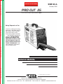
PRO-CUT 25
For use with machine code numbers 10661
Return to Master TOC
View Safety Info
View Safety Info
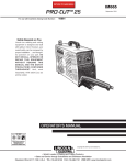
Safety Depends on You
Return to Master TOC
Return to Master TOC
RETURN TO MAIN MENU
Lincoln arc welding and cutting
equipment is designed and built
with safety in mind. However,
your overall safety can be
increased by proper installation
. . . and thoughtful operation on
your part. DO NOT INSTALL,
OPERATE OR REPAIR THIS
EQUIPMENT WITHOUT READING THIS MANUAL AND THE
SAFETY PRECAUTIONS CONTAINED THROUGHOUT. And,
most importantly, think before
you act and be careful.
View Safety Info
Return to Master TOC
SERVICE MANUAL
Copyright © 2006 Lincoln Global Inc.
• World's Leader in Welding and Cutting Products •
• Sales and Service through Subsidiaries and Distributors Worldwide •
Cleveland, Ohio 44117-1199 U.S.A. TEL: 1-888-935-3877 FAX: 216.486.1751 WEB SITE: www.lincolnelectric.com
Return to Master TOC
i
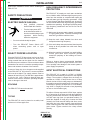
PLASMA CUTTING or GOUGING can be hazardous.
PROTECT YOURSELF AND OTHERS FROM POSSIBLE SERIOUS INJURY OR DEATH. KEEP CHILDREN
AWAY. PACEMAKER WEARERS SHOULD CONSULT WITH THEIR DOCTOR BEFORE OPERATING.
Read and understand the following safety highlights. For additional safety information it is strongly recommended that you purchase a copy of “Safety in Welding & Cutting - ANSI Standard Z49.1” from the American Welding Society, P.O. Box 351040,
Miami, Florida 33135 or CSA Standard W117.2.
BE SURE THAT ALL INSTALLATION, OPERATION, MAINTENANCE, AND REPAIR PROCEDURES ARE
PERFORMED ONLY BY QUALIFIED INDIVIDUALS.
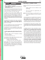
ELECTRIC SHOCK can kill.
1.a. The electrode and work (or ground) circuits
are electrically “hot” when the power source is on.
Do not touch these “hot” parts with your bare skin
or wet clothing. Wear dry, hole-free gloves to insulate hands.
Return to Master TOC
1.b. When the power source is operating voltages in excess of 250
volts are produced. This creates the potential for serious electrical shock - potentially even fatal.
1.c. Insulate yourself from work and ground using dry insulation.
When cutting or gouging in damp locations, on metal framework such as floors, gratings or scaffolds and when in positions such as sitting or lying, make certain the insulation is
large enough to cover your full area of physical contact with
work and ground.
1.d. Always be sure the work cable makes a good electrical connection with the metal being cut or gouged. The connection
should be as close as possible to the area being cut or
gouged.
1.e. Ground the work or metal to be cut or gouged to a good electrical (earth) ground.
1.f. Maintain the plasma torch, cable and work clamp in good, safe
operating condition. Replace damaged insulation.
1.g. Never dip the torch in water for cooling or plasma cut or gouge
in or under water.
Return to Master TOC
1.h. When working above floor level, protect yourself from a fall
should you get a shock.
1.i. Operate the pilot arc with caution. The pilot arc is capable of
burning the operator, others or even piercing safety clothing.
FUMES AND GASES
can be dangerous.
3.a. Plasma cutting or gouging may produce
fumes and gases hazardous to health. Avoid
breathing these fumes and gases. When cutting
or gouging, keep your head out of the fumes. Use
enough ventilation and/or exhaust at the arc to
keep fumes and gases away from the breathing zone. When
plasma cutting or gouging on lead or cadmium plated
steel and other metals or coatings which produce highly
toxic fumes keep exposure as low as possible and below
Threshold Limit Values (TLV) using local exhaust or
mechanical ventilation. In confined spaces or in some
circumstances, outdoors, a respirator may be required.
Additional precautions are also required when plasma
cutting or gouging on galvanized steel.
3. b. The operation of plasma cutting or gouging fume control
equipment is affected by various factors including proper use
and positioning of the equipment, maintenance of the equipment and the specific procedure and applicaiton involved.
Worker exposure level should be checked upon installation
and periodically thereafter to be certain it is within applicable
OSHA PEL and ACGIH TLV limits.
3.c. Do not use plasma cutting or gouging equipment in locations
near chlorinated hydrocarbon vapors coming from degreasing, cleaning or spraying operations. The heat and rays of the
arc can react with solvent vapors to form phosgene, a highly
toxic gas, and other irritating products.
3.d. Gases used for plasma cutting and gouging can displace air
and cause injury or death. Always use enough ventilation,
especially in confined areas, to insure breathing air is safe.
3.e. Read and understand the manufacturer’s instructions for this
equipment and follow your employer’s safety practices.
1.j. Also see Items 4c and 6.
ARC RAYS can burn.
2.a. Use safety glasses and a shield with the proper filter and cover plates to protect your eyes from
sparks and the rays of the arc when performing or
observing plasma arc cutting or gouging.
Glasses,headshield and filter lens should conform
to ANSI Z87. I standards.
Return to Master TOC
i
SAFETY
2.b. Use suitable clothing including gloves made from durable
flame-resistant material to protect your skin and that of your
helpers from the arc rays.
2.c. Protect other nearby personnel with suitable non-flammable
screening and/or warn them not to watch the arc nor expose
themselves to the arc rays or to hot spatter or metal.
CUTTING SPARKS can
cause fire or explosion.
4.a..Remove fire hazards from the plasma cutting
or gouging area. If this is not possible, cover them
to prevent the cutting or gouging sparks from
starting a fire. Remember that welding sparks
and hot materials from plasma cutting or gouging can easily
go through small cracks and openings to adjacent areas.
Avoid cutting or gouging near hydraulic lines. Have a fire
extinguisher readily available.
4.b. Where compressed gases are to be used at the job site, special precautions should be used to prevent hazardous situations. Refer to “Safety in Welding and Cutting” (ANSI Standard
Z49.1) and the operating information for the equipment being
used.
Aug. ‘06
Return to Master TOC
ii
4.c. When not cutting or gouging, make certain no part of the electrode circuit is touching the work or ground. Accidental contact
can cause overheating and create a fire hazard.
FOR ELECTRICALLY
powered equipment.
4.d. Do not cut or gouge tanks, drums or containers until the proper
steps have been taken to insure that such procedures will not
cause flammable or toxic vapors from substances inside. They
can cause an explosion even though they have been “cleaned.”
For information purchase “Recommended Safe Practices for
the Preparation for Welding and Cutting of Containers and
Piping That Have Held Hazardous Substances”, AWS F4.1 from
the American Welding Society (see address above).
6.a. Turn off input power using the disconnect
switch at the fuse box before working on the
equipment.
4.e. Vent hollow castings or containers before heating, cutting or
gouging. They may explode.
6.b. Install equipment in accordance with the U.S. National
Electrical Code, all local codes and the manufacturer’s recommendations.
6.c. Ground the equipment in accordance with the U.S. National
Electrical Code and the manufacturer’s recommendations.
4.f. Do nor fuel engine driven equipment near area where plasma
cutting or gouging.
Return to Master TOC
ii
SAFETY
PLASMA ARC can injure.
4.g. Sparks and spatter are thrown from the plasma arc. Wear safety glasses, ear protection and oil free protective garments such
as leather gloves, heavy shirt, cuffless trousers, high shoes
and a cap over your hair. Wear ear plugs when cutting or gouging out of position or in confined places. Always wear safety
glasses with side shields when in a cutting or gouging area.
4.h. Connect the work cable to the work as close to the cutting or
gouging area as practical. Work cables connected to the building framework or other locations away from the cutting or gouging area increase the possibility of the current passing through
lifting chains, crane cables or other alternate circuits. This can
create fire hazards or overheat lifting chains or cables until they
fail.
7.a. Keep your body away from nozzle and
plasma arc.
7.b. Operate the pilot arc with caution. The pilot arc is capable of
burning the operator, others or even piercing safety clothing.
ELECTRIC AND MAGNETIC FIELDS
may be dangerous
8.a. Electric current flowing through any conductor causes localized Electric and Magnetic Fields
(EMF). Cutting or gouging current creates EMF
fields around torch cables and cutting machines.
Return to Master TOC
CYLINDER may explode
if damaged.
5.a. Use only compressed gas cylinders containing the correct gas for the process used and
properly operating regulators designed for the
gas and pressure used. All hoses, fittings, etc.
should be suitable for the application and maintained in good
condition.
5.b. Always keep cylinders in an upright position securely chained
to an undercarriage or fixed support.
5.c. Cylinders should be located:
• Away from areas where they may be struck or subjected to
physical damage.
• A safe distance from plasma cutting or gouging, arc welding operations and any other source of heat, sparks,
or flame.
5.d. Never allow any part of the electrode, torch or any other electrically “hot” parts to touch a cylinder.
5.e. Keep your head and face away from the cylinder valve outlet
when opening the cylinder valve.
Return to Master TOC
5.f. Valve protection caps should always be in place and hand
tight except when the cylinder is in use or connected for use.
5.g. Read and follow the instructions on compressed gas cylinders, associated equipment, and CGA publication P-l,
“Precautions for Safe Handling of Compressed Gases in
Cylinders,”available from the Compressed Gas Association
1235 Jefferson Davis Highway, Arlington, VA 22202.
8.b. EMF fields may interfere with some pacemakers, so operators having a pacemaker
should consult their physician before cutting or
gouging.
8.c. Exposure to EMF fields during cutting or gouging may have
other health effects which are now not known.
8d. All operators should use the following procedures in order to
minimize exposure to EMF fields from the cutting or gouging
circuit:
8.d.1. Route the torch and work cables together - Secure
them with tape when possible.
8.d.2. Never coil the torch cable around your body.
8.d.3. Do not place your body between the torch and
work cables. If the torch cable is on your right side,
the work cable should also be on your right
side.
8.d.4. Connect the work cable to the workpiece as close as
possible to the area being cut or gouged.
8.d.5. Do not work next to cutting power source.
Apr. ‘93
Return to Master TOC
Return to Master TOC
Return to Master TOC
Return to Master TOC
iii
SAFETY
iii
PRÉCAUTIONS DE SÛRETÉ
6. Eloigner les matériaux inflammables ou les recouvrir afin de
prévenir tout risque d’incendie dû aux étincelles.
Pour votre propre protection lire et observer toutes les instructions
et les précautions de sûreté specifiques qui parraissent dans ce
manuel aussi bien que les précautions de sûreté générales suivantes:
7. Quand on ne soude pas, poser la pince à une endroit isolé de
la masse. Un court-circuit accidental peut provoquer un
échauffement et un risque d’incendie.
Sûreté Pour Soudage A L’Arc
1. Protegez-vous contre la secousse électrique:
a. Les circuits à l’électrode et à la piéce sont sous tension
quand la machine à souder est en marche. Eviter toujours
tout contact entre les parties sous tension et la peau nue
ou les vétements mouillés. Porter des gants secs et sans
trous pour isoler les mains.
b. Faire trés attention de bien s’isoler de la masse quand on
soude dans des endroits humides, ou sur un plancher metallique ou des grilles metalliques, principalement dans
les positions assis ou couché pour lesquelles une grande
partie du corps peut être en contact avec la masse.
c. Maintenir le porte-électrode, la pince de masse, le câble de
soudage et la machine à souder en bon et sûr état defonctionnement.
d.Ne jamais plonger le porte-électrode dans l’eau pour le
refroidir.
e. Ne jamais toucher simultanément les parties sous tension
des porte-électrodes connectés à deux machines à souder
parce que la tension entre les deux pinces peut être le total
de la tension à vide des deux machines.
f. Si on utilise la machine à souder comme une source de
courant pour soudage semi-automatique, ces precautions
pour le porte-électrode s’applicuent aussi au pistolet de
soudage.
2. Dans le cas de travail au dessus du niveau du sol, se protéger
contre les chutes dans le cas ou on recoit un choc. Ne jamais
enrouler le câble-électrode autour de n’importe quelle partie du
corps.
8. S’assurer que la masse est connectée le plus prés possible de
la zone de travail qu’il est pratique de le faire. Si on place la
masse sur la charpente de la construction ou d’autres endroits
éloignés de la zone de travail, on augmente le risque de voir
passer le courant de soudage par les chaines de levage,
câbles de grue, ou autres circuits. Cela peut provoquer des
risques d’incendie ou d’echauffement des chaines et des
câbles jusqu’à ce qu’ils se rompent.
9. Assurer une ventilation suffisante dans la zone de soudage.
Ceci est particuliérement important pour le soudage de tôles
galvanisées plombées, ou cadmiées ou tout autre métal qui
produit des fumeés toxiques.
10. Ne pas souder en présence de vapeurs de chlore provenant
d’opérations de dégraissage, nettoyage ou pistolage. La
chaleur ou les rayons de l’arc peuvent réagir avec les vapeurs
du solvant pour produire du phosgéne (gas fortement toxique)
ou autres produits irritants.
11. Pour obtenir de plus amples renseignements sur la sûreté, voir
le code “Code for safety in welding and cutting” CSA Standard
W 117.2-1974.
PRÉCAUTIONS DE SÛRETÉ POUR
LES MACHINES À SOUDER À
TRANSFORMATEUR ET À
REDRESSEUR
3. Un coup d’arc peut être plus sévère qu’un coup de soliel, donc:
a. Utiliser un bon masque avec un verre filtrant approprié ainsi
qu’un verre blanc afin de se protéger les yeux du rayonnement de l’arc et des projections quand on soude ou
quand on regarde l’arc.
b. Porter des vêtements convenables afin de protéger la peau
de soudeur et des aides contre le rayonnement de l‘arc.
c. Protéger l’autre personnel travaillant à proximité au
soudage à l’aide d’écrans appropriés et non-inflammables.
4. Des gouttes de laitier en fusion sont émises de l’arc de
soudage. Se protéger avec des vêtements de protection libres
de l’huile, tels que les gants en cuir, chemise épaisse, pantalons sans revers, et chaussures montantes.
5. Toujours porter des lunettes de sécurité dans la zone de
soudage. Utiliser des lunettes avec écrans lateraux dans les
zones où l’on pique le laitier.
1. Relier à la terre le chassis du poste conformement au code de
l’électricité et aux recommendations du fabricant. Le dispositif
de montage ou la piece à souder doit être branché à une
bonne mise à la terre.
2. Autant que possible, I’installation et l’entretien du poste seront
effectués par un électricien qualifié.
3. Avant de faires des travaux à l’interieur de poste, la debrancher à l’interrupteur à la boite de fusibles.
4. Garder tous les couvercles et dispositifs de sûreté à leur place.
iv
iv
MASTER TABLE OF CONTENTS FOR ALL SECTIONS
RETURN TO MAIN MENU
Page
Safety .................................................................................................................................................i-iii
Installation .............................................................................................................................Section A
Technical Specifications .............................................................................................................A-2
Safety Precautions......................................................................................................................A-3
Select Proper Location ...............................................................................................................A-3
Stacking ......................................................................................................................................A-3
Tilting...........................................................................................................................................A-3
High Frequency Interference Protection.....................................................................................A-3
Input Electrical Connections.......................................................................................................A-3
Gas Input Connections ...............................................................................................................A-4
Output Connections....................................................................................................................A-5
Torch .....................................................................................................................................A-5
Operation...............................................................................................................................Section B
Safety Precautions ....................................................................................................................B-2
Description ................................................................................................................................B-2
Preheating Temperature .............................................................................................................B-2
User Responsibilities .................................................................................................................B-3
Operational Features and Controls ............................................................................................B-3
Design Features and Advantages ..............................................................................................B-3
Cutting Capability .......................................................................................................................B-4
Consumable Life.........................................................................................................................B-4
Limitations ..................................................................................................................................B-5
Controls and Settings .................................................................................................................B-5
Pilot Arc Discussion....................................................................................................................B-6
Procedure Recommendations ....................................................................................................B-7
General .................................................................................................................................B-7
Suggestions For Extra Utility From The Pro-Cut System ....................................................B-7
Accessories ..........................................................................................................................Section C
Maintenance .........................................................................................................................Section D
Theory of Operation .............................................................................................................Section E
Troubleshooting and Repair.................................................................................................Section F
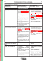
How to Use Troubleshooting Guide............................................................................................F-2
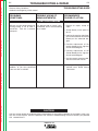
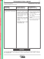
Troubleshooting Guide ................................................................................................................F-4
Test Procedures ..........................................................................................................................F-9
Replacement Procedures .........................................................................................................F-29
Electrical Diagrams ..............................................................................................................Section G
Parts Manual (Pro Cut 25)...............................................................................................P-357 Series
Cutting Torch ...................................................................................................P-210-U
PRO-CUT 25
Return to Master TOC
Return to Master TOC
Return to Master TOC
Return to Master TOC
NOTES
PRO-CUT 25
Return to Master TOC
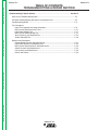
Section A-1
TABLE OF CONTENTS
- INSTALLATION SECTION -
Section A-1
Installation
Technical Specifications .............................................................................................................A-2
Safety Precautions......................................................................................................................A-3
Select Proper Location ...............................................................................................................A-3
Stacking ......................................................................................................................................A-3
Tilting ..........................................................................................................................................A-3
High Frequency Interference Protection.....................................................................................A-3
Gas Input Connections...............................................................................................................A-4
Output Connections ...................................................................................................................A-5
Torch .....................................................................................................................................A-5
Return to Master TOC
Return to Master TOC
Return to Master TOC
Input Electrical Connections.......................................................................................................A-3
PRO-CUT 25
Return to Master TOC
Return to Section TOC
A-2
A-2
INSTALLATION
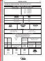
TECHNICAL SPECIFICATIONS - PRO-CUT 25 (K1756-1)
INPUT - SINGLE PHASE / 60 HERTZ ONLY
Standard Voltage
1Ø Input Current at Rated Output
115/230/1/50/60Hz
115 V : 15 A @ 20%
115 V : 26.7A@ 60%
115 V : 37.7A@ 35%
230 V : 15 A@100%
230 V : 19 A @ 60%
Return to Master TOC
Return to Section TOC
RATED OUTPUT
AMPS
15 A
20 A
20 A
25 A
25 A
Duty Cycle
20% on 115 V
60% on 115 V
100% on 230 V
35% on 115 V
60% on 230 V
OUTPUT
Open Circuit
Voltage
400 VDC
Current
Range
12-25 Amps
REQUIRED GAS FLOW RATE
12 Amps
REQUIRED GAS INLET PRESSURE
55 PSI @ 240 SCFH
( 3.8 Bar. @ 6800 LHR)
65 to 150 PSI
(4.5 Bar. TO 10.3 Bar.)
RECOMMEND INPUT WIRE AND FUSE SIZES
Return to Master TOC
Return to Section TOC
Pilot Current
For all plasma cutting applications
Based on U.S. National Electrical Code
Ambient Temperature 30oC or Less
Output AC Input
Voltage
at
50/60
Hertz
Input Cord
Plug
Size
25 A 230V-1Ø
6-20P or 6-30P or 6-50P
Fuse
(Super Lag)
Circuit Breaker
(Delay Type)
15 A 115V-1Ø 5-15P* or 5-20P* or 5-30P or 5-50P
20 A 115V-1Ø 5-20P* or 5-30P or 5-50P
25 A 115V-1Ø
5-30P or 5-50P
20 AMPS
Type 75oC
Copper Wire in Conduit
AWG (IEC) Sizes
2 Input Supply Wires 1 Ground Wire
#14 (2.5 mm2)
#14 (2.5 mm2)
15 AMPS
20 AMPS
30 AMPS
#12 (4 mm2)
#12 (4 mm2)
#12 (4 mm2)
#12 (4 mm2)
#12 (4 mm2)
#12 (4 mm2)
Return to Master TOC
Return to Section TOC
PHYSICAL DIMENSIONS
Height
Width
Depth
10.2 in.
260 mm
6.3 in.
160 mm
16.1 in.
410 mm
* Included with machine
PRO-CUT 25
Weight
Including
Torch Cable
35 lbs.
15.9 kg.
Return to Master TOC
Return to Master TOC
Return to Section TOC
Return to Section TOC
A-3
INSTALLATION
Read entire Installation Section before installing the
PRO-CUT 25.
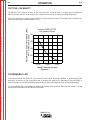
HIGH FREQUENCY INTERFERENCE
PROTECTION
SAFETY PRECAUTIONS
The PRO-CUT 25 employs a touch start mechanism
for arc initiation which eliminates high frequency emissions from the machine as compared with spark gap
and solid state type high frequency generators. Keep
in mind, though, that these machines may be used in
an environment where other high frequency generating
machines are operating. By taking the following steps,
high frequency interference into the Pro-Cut can be
minimized
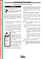
WARNING
ELECTRIC SHOCK CAN KILL.
•
•
Only qualified personnel
should install this machine.
•
Turn the input power OFF
at the disconnect switch or
fuse box and discharge input
capacitors before working
inside the equipment.
Return to Master TOC
Return to Section TOC
•
Turn the PRO-CUT Power Switch OFF
when connecting power cord to input
power.
___________________________________________
Place the PRO-CUT 25 where clean cool air can freely
circulate in and out the side louvers. Dirt, dust or any
foreign material that can be drawn into the machine
should be kept at a minimum. Failure to observe these
precautions can result in excessive operating temperatures and nuisance shutdown of the machine.
A source of clean, dry air or nitrogen must be supplied
to the PRO-CUT 25. Oil in the air is a severe problem
and must be avoided. The supply pressure must be
between 80 and 150 psi. The flow rate is approximately 4.0 cfm (113 l/min.). Failure to observe these precautions could result in excessive operating temperatures or damage to the torch.
STACKING
The PRO-CUT 25 cannot be stacked.
Return to Master TOC
(1) Make sure the power supply chassis is connected
to a good earth ground. The work terminal ground
does NOT ground the machine frame.
(2) Keep the work clamp isolated from other work
clamps that have high frequency.
Do not touch electrically hot parts.
SELECT PROPER LOCATION
Return to Section TOC
A-3
TILTING
The PRO-CUT 25 must be placed on a stable, level
surface so it will not topple over.
(3) If the work clamp cannot be isolated, then keep the
clamp as far as possible from other work clamp
connections.
(4) When the machine is enclosed in a metal building,
several good earth driven electrical grounds
around the periphery of the building are recommended.
Failure to observe these recommended installation
procedures may cause improper function of the ProCut or possibly even damage to the control system or
power supply components.
INPUT ELECTRICAL CONNECTIONS
The PRO-CUT 25 is rated for 115VAC or 230VAC
inputs and will automatically reconnect for the supplied
voltage. The machine is shipped from the factory for
operation on 115VAC 15 amp circuits. Use on 15 amp
branch circuits will limit cutting output as indicated by
the graphics around the output knob. If the output is set
at 20 amps or greater, the input fuse or circuit breaker
may “blow” in roughly 30 seconds or less (depending
on fuse or circuit breaker type).
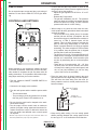
To achieve 20 amp output with 115VAC input, replace
the 15 amp plug on the input cord with the supplied 20
amp plug, and connect the unit to a 20 amp branch circuit with super lag fuses (or equivalent breaker). To
install the supplied 20 amp plug: Connect the white
(neutral) wire under terminal clamp with silver screw,
and black (hot) wire under terminal clamp with brass
screw. Connect green wire under terminal clamp with
green screw. Tighten terminal wire clamp screws
securely.
PRO-CUT 25
Return to Master TOC
Return to Master TOC
Return to Section TOC
Return to Section TOC
A-4
INSTALLATION
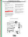
GAS INPUT CONNECTIONS
WARNING
• Failure to wire as instructed may cause personal
injury or damage to equipment.
• To be installed or checked by an electrician or
qualified person only.
-----------------------------------------------------------------------Use of normal 20 amp household breakers may result
in over current trips. If breaker trips occur, reduce the
cutting current output until nuisance trips stop.
To achieve the full 25 amp output capability of the
machine with 115 VAC input, remove the 15 amp or 20
amp plug on the input cord and install a 30 amp or 50
amp plug designed for 115 VAC (NEMA style 5-30P or
5-50P). Follow the instructions included with the plug.
Connect to an appropriate branch circuit with a mating
receptacle.
The PRO-CUT 25 performs best when connected to
230VAC inputs. To change over to 230VAC operation,
install a 230VAC plug with a current rating equal to or
greater than 20 amps.
For use on engine drives, keep in mind the above input
draw restrictions and the following precaution.
Return to Master TOC
Return to Section TOC
The PRO-CUT 25 can be operated on engine driven
generators as long as the 230 volt auxiliary meets the
following conditions:
• The AC waveform peak voltage is below 400 volts*.
• The AC waveform frequency is between 45 and 65
Hz.
• The RMS voltage of the AC waveform is always
greater than 208VAC *.
* for 115 VAC input divide these values in half
The following Lincoln engine drives meet these conditions when run in the high idle mode:
Ranger 200 & 250 engine drives
Commander 300, 400, & 500 engine drives
Return to Master TOC
Some engine drives do not meet these conditions (eg
Miller Bobcats, etc). Operation of the PRO-CUT 25 is
not recommended on engine drives not conforming to
these conditions. Such combinations may overvoltage
the PRO-CUT 25 power source.
Return to Section TOC
A-4
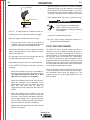
Supply the PRO-CUT 25 with clean compressed air or
nitrogen.
•
Supply pressure must be between 80 psi
and 150 psi.
•
Flow rate should be approximately 4.0
cfm (113 I/min.).
NOTE: Oil in the air supply to the PRO-CUT 25 can
cause severe problems. Use only a clean air
supply.
• Compressed gas can be supplied either through the air
fitting supplied with the machine or through the 1/4-19
BSPP thread at the rear of the machine. To use the air
fitting supplied with the machine (packaged in the consumable kit), apply teflon tape to the fitting threads and
install the fitting in the port at the rear of the machine.
• If compressed air is being used, it is highly recommended that an inline filter be installed in the air supply line ahead of the air connection to the PRO-CUT
25.
• A standard nominal 5 micron inline filter is recommended; however, for optimum performance,select a
prefilter with a 3 micron absolute rating. If these filter
ratings are unavailable, anything with a rating less
than, or equal to, 20 micron would be acceptable to
use. In line filter elements will generally filter the air
with little restriction to the airflow until the element is
about 75% contaminated. After this point, there will
be a noticeable pressure drop in the line. Filter elements should be replaced when a pressure drop of 810 psi is indicated; however, for optimum performance of the PRO-CUT 25, the filter element should
be replaced at or before the pressure drop reaches 8
psi. Be sure to select a filter that will accommodate
the necessary flow rating for the PRO-CUT 25 as
specified in the Installation section of this instruction
manual under the Gas Input Connections heading.
PRO-CUT 25
Return to Master TOC
Return to Section TOC
A-5
INSTALLATION
NOTE: When using nitrogen gas from a cylinder, the
cylinder must have a pressure regulator.
•
Maximum psi from a nitrogen gas cylinder to
the PRO-CUT 25 regulator should never
exceed 150 psi.
•
Install a hose between the nitrogen gas
cylinder regulator and the PRO-CUT 25
gas inlet
.
WARNING
Return to Master TOC
Return to Section TOC
CYLINDER could explode if damaged.
• Keep cylinder upright and chained
to a fixed support.
• Keep cylinder away from areas where it could be
damaged.
• Never lift machine with cylinder attached.
• Never allow the cutting torch to touch the cylinder.
• Keep cylinder away from live electrical parts.
Return to Section TOC
Return to Master TOC
Return to Section TOC
Return to Master TOC
• Maximum inlet pressure 150 psi.
__________________
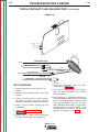
OUTPUT CONNECTIONS
Torch
The PRO-CUT 25 is sent from the factory with a 15’
PCT 20 cutting torch installed. Additional cutting torches can be ordered from the K1615 series. Hand-held
torches come with 15' or 25’ cables.
PRO-CUT 25
A-5
Return to Section TOC
Return to Master TOC
Return to Section TOC
Return to Master TOC
Return to Master TOC
Return to Section TOC
Return to Master TOC
Return to Section TOC
A-6
NOTES
PRO-CUT 25
A-6
Return to Master TOC
Section B-1
Section B-1
TABLE OF CONTENTS
- OPERATION SECTION Operation...............................................................................................................................Section B
Safety Precautions......................................................................................................................B-2
Description .................................................................................................................................B-2
Preheating Temperature .............................................................................................................B-2
User Responsibility ....................................................................................................................B-3
Operational Features and Controls ............................................................................................B-3
Design Features and Advantages...............................................................................................B-3
Cutting Capability .......................................................................................................................B-4
Consumable Life.........................................................................................................................B-4
Controls and Settings .................................................................................................................B-5
Pilot Arc Discussion ................................................................................................................... B-6
Procedure Recommendations ....................................................................................................B-7
General .................................................................................................................................B-7
Suggestions for Extra Utility From the Pro-Cut System ......................................................B-7
Return to Master TOC
Return to Master TOC
Return to Master TOC
Limitations...................................................................................................................................B-5
PRO-CUT 25
Return to Master TOC
Return to Section TOC
B-2
OPERATION
Read and understand this entire section before operating the machine.
DESCRIPTION
SAFETY PRECAUTIONS
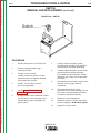
The PRO-CUT 25 is a constant current, continuous
control plasma cutting power source. It provides superior and reliable starting characteristics, cutting visibility and arc stability. The control system has a safety
mechanism to insure that the nozzle and electrode are
in place before cutting or gouging. This is extremely
important due to the high voltages involved.
WARNING
ELECTRIC SHOCK
can kill.
• Do not touch electrically live parts
or electrode with skin or wet
clothing.
Return to Master TOC
Return to Section TOC
• Insulate yourself from work and
ground.
• Always wear dry insulating
gloves.
• Keep your head out of fumes.
• Use ventilation or exhaust to
remove fumes from breathing
zone.
PREHEAT TEMPERATURE FOR
PLASMA CUTTING
Return to Master TOC
• Keep flammable material away.
Return to Section TOC
The PRO-CUT 25 comes standard with an air regulator and pressure gauge. The machine also comes with
an input power cord. Hand-held torches are available
in 15' or 25' cable. Consumables are included with
each Pro-Cut purchase so that cutting can begin right
out of the box. Consumables can also be ordered as
individual packages.
The PRO-CUT 25 initiates the plasma arc with a simple, yet reliable, touch start mechanism. This system
eliminates many of the failure problems associated
with hi-frequency start systems.
FUMES AND GASES
can be dangerous.
WELDING, CUTTING and
GOUGING SPARKS
can cause fire or explosion
• Do not weld, cut or gouge on
containers that have held combustibles.
ARC RAYS
can burn.
• Wear eye, ear and body
protection.
Preheat temperature control is not necessary in most
applications when plasma arc cutting or gouging.
Preheat temperature control may be necessary on high
carbon alloy steels and heat treated aluminum for crack
resistance and hardness control. Job conditions, prevailing codes, alloy level, and other considerations may
also require preheat temperature control. The following
minimum preheat temperature is recommended as a
starting point. Higher temperatures may be used as
required by the job conditions and/or prevailing codes. If
cracking or excessive hardness occurs on the cut face,
higher preheat temperature may be required. The recommended minimum preheat temperature for plate
thickness up to 1/2" (12.7mm) is 70°F (21.1°C).
PLASMA ARC
can injure
Return to Master TOC
• Keep your body away from nozzle
and plasma arc.
Return to Section TOC
B-2
• Operate the pilot arc with caution. The
pilot arc is capable of burning the
operator, others or even piercing
safety clothing.
Observe additional Safety Guidelines detailed in
the beginning of this manual.
PRO-CUT 25
Return to Master TOC
Return to Master TOC
Return to Master TOC
Return to Master TOC
Return to Section TOC
Return to Section TOC
Return to Section TOC
Return to Section TOC
B-3
OPERATION
B-3
USER RESPONSIBILITY
- Continuous control, 12 - 25 amps.
Because design, fabrication, erection and cutting variables affect the results obtained in applying this type of
information, the serviceability of a product or structure
is the responsibility of the user. Variation such as plate
chemistry, plate surface condition (oil, scale), plate
thickness, preheat, quench, gas type, gas flowrate
and equipment may produce results different than
those expected. Some adjustments to procedures may
be necessary to compensate for unique individual conditions. Test all procedures duplicating actual field conditions.
- Reliable touch start mechanism for plasma arc initiation.
OPERATIONAL FEATURES AND
CONTROLS
- Parts-in-Place mechanism to detect proper installation of consumables and torch.
The PRO-CUT 25 comes with an ON/OFF POWER
SWITCH, OUTPUT CURRENT CONTROL, and
PURGE BUTTON.
- Rapid arc restrike for fast cutting of expanded metal.
- Input over voltage protection.
- Bright 3.0 second timed pilot arc.
- Purge momentary push button.
- Air regulator and pressure gage included.
- Latching Parts-in-Place mechanism. Requires the
operator to turn the machine off and then on to reset.
- Preflow/Postflow timing. Preflow is eliminated if arc
is re-initiated in Postflow.
DESIGN FEATURES AND
ADVANTAGES
- Thermostatic Protection.
The PRO-CUT 25 design makes plasma cutting
uncomplicated. This list of design features and advantages will help you understand the machine's total
capabilities so that you can get maximum use from
your machine.
- Solid state over-current protection.
- Light weight and portable design for industrial use.
- Unique electrode and Vortech™ nozzle design for
optimum cooling and long life.
- Automatic reconnect for 115 VAC or 230 VAC inputs.
- Dead front display for machine status.
- Swirl texture inside Vortech™ nozzle for better starting reliability and higher quality cuts.
PRO-CUT 25
OPERATION
B-4
CUTTING CAPABILITY
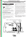
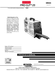
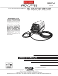
The PRO-CUT 25 is rated at 25 amps, at 35% duty cycle on a 10 minute basis. If the duty cycle is exceeded, a
thermal protector will shut off the output of the machine until it cools to the normal operating temperature.
Figure B.1 shows the cut capacity of the PRO-CUT 25 when cutting mild steel. (The graph plots cut thickness vs.
torch travel speed with a torch standoff of 0.15".)
Recommended Torch Travel Speed (IPM)
80% of Maximum Speed
Return to Master TOC
Return to Master TOC
Return to Master TOC
Return to Section TOC
Return to Section TOC
Return to Section TOC
B-4
Lincoln's PRO-CUT 25
Cut Capacity Chart
80
60
40
20
0
0.125
0.375
0.250
Metal Thickness (Inches)
Figure B.1
CONSUMABLE LIFE
The expected life for the PRO-CUT 25's electrode under normal operating conditions is approximately 1000
starts/cuts. An erosion of .060" is typical for end of electrode life, however, the electrode life may last longer. A
green and erratic arc will indicate definite electrode failure and the electrode should be replaced immediately.
Return to Master TOC
Return to Section TOC
It is recommended that consumables be replaced in complete sets. (Example: Electrode and Nozzle). This will
maximize the performance of the PRO-CUT 25 system.
PRO-CUT 25
Return to Master TOC
LIMITATIONS
Do not exceed output current and duty cycle rating of
machine. Do not use the PRO-CUT 25 for pipe thawing.
CONTROLS AND SETTINGS
PRESSURE REGULATOR
CAP
When preparing to cut, position the machine as close
to the work as possible. Make sure you have all materials needed to complete the job and have taken all
safety precautions. It is important to follow these operating steps each time you use the machine.
• Turn the machine's ON/OFF POWER SWITCH to
OFF position.
• Push-in and hold the Purge button to check or set
the gas pressure. Pull the pressure regulator cap out
and turn it to set the pressure.
- Adjust the gas regulator for 65 PSI for 15’ or 25’
torches.
- Release the Purge button.
- The gas will immediately turn off. The pressure
gage may show an increase in pressure after the
air turns off but this is normal. Do NOT reset the
pressure while the air is NOT flowing.
• When ready to cut, place the torch near the work,
make certain all safety precautions have been taken
and pull the trigger.
- The air will flow for a preflow time of 2 seconds
and the pilot arc will start. (Exceptions: the first
time that the trigger is pulled after the machine is
turned on, or after a thermal tripout, will be
ignored. This is a safety feature to prevent the
pilot arc from firing unexpectedly or if the torch
button is pressed because it is laying up against
something. The other exception is if the machine
is in postflow, then the preflow time is skipped
and the pilot arc will start immediately.)
- The pilot arc will run for 3.0 seconds and shut off
unless the arc is brought in contact with the work
and the arc is transferred. Avoid excessive pilot
arc time by transferring the arc to the workpiece
quickly.
- When the arc is brought within 1/8” - 1/4" from
the work piece: the arc will transfer, the current
will ramp to the setting on the control panel, and
the cut can last indefinitely (or until the duty
cycle of the Pro-Cut is exceeded).
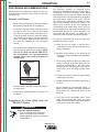
• Pierce the work piece by slowly lowering the torch
onto the metal at a 300 angle away from the operator.
This will blow the dross away from the torch tip.
Slowly rotate the torch to vertical position as the arc
becomes deeper.
• Connect the air supply to the machine.
TORCH AT 300 ANGLE
TO PIERCE
Return to Master TOC
• Turn the main power and the machine power switch
on.
- The fan should start.
- The pre-charge circuit will operate for 3 seconds,
then the green "Power" LED should turn on.
Return to Section TOC
B-5
OPERATION
Return to Master TOC
Return to Master TOC
Return to Section TOC
Return to Section TOC
Return to Section TOC
B-5
• Be sure that the work lead is clamped to the workpiece before cutting.
• Set the output current control knob at maximum1
position for higher cutting speed and less dross formation. Reduce the current, if desired to reduce the
kerf (cut) width, heat affected zone or travel speed
as required.
1
Maximum output requires a 30 amp input circuit and breaker. Refer to the
Technical Specifications for proper input circuit guidelines.
ROTATE TO
900 ANGLE TO CUT
300
900
VERTICAL ANGLE
VERTICAL
FOR CUTTING
CUT
• Keep moving while cutting. Cut at a steady speed
without pausing. Maintain the cutting speed so that
the arc leg is 10° to 20° behind the travel direction.
PRO-CUT 25
Return to Master TOC
Return to Section TOC
B-6
5° - 15°
• After the problem is found, or if there is nothing
apparently wrong, reset the machine by turning the
power switch OFF and then ON again. (It is possible for electrical noise to trip the safety circuit on rare
occasions. This should not be a regular occurrence.)
Leading Angle
• If the machine does not reset or continues to trip,
Direction of Travel
WARNING
10° - 20° Arc Lag
• Use a 5° - 15° leading angle in the direction of the cut.
Return to Master TOC
Return to Section TOC
• Finish the cut to be made and release the trigger.
• When the trigger is released, the arc will stop.
- The gas will continue to flow for 10 seconds of
postflow. If the trigger is activated within this time
period, the pilot arc will immediately restart.
• If the dross is difficult to remove, reduce the cutting
speed. High speed dross is more difficult to remove
than low speed dross.
• The right side of the cut is more square than the left
as viewed along the direction of travel.
Return to Master TOC
Return to Master TOC
Return to Section TOC
• Clean spatter and scale from the nozzle frequently.
Return to Section TOC
B-6
OPERATION
• If the "SAFETY" LED lights at any time; check the
following:
• Check the assembly of the torch consumables. If
they are not properly in place, the machine will not
start. Make sure that the shield cup is hand
tight. Do not use pliers or over tighten.
ELECTRIC SHOCK CAN KILL.
• Turn off machine at the disconnect
switch on the front of the machine
before tightening, cleaning or replacing
consumables.
---------------------------------------------------------------------------consult the Troubleshooting Section.
• Use the proper cutting procedures referred to in
Procedure Recommendations.
PILOT ARC DISCUSSION
The PRO-CUT has a smooth, continuous pilot arc.
The pilot arc is only a means of transferring the arc to
the workpiece for cutting. Repeated pilot arc starts, in
rapid succession, is not recommended as these starts
will generally reduce consumable life. Occasionally,
the pilot arc may sputter or start intermittently. This is
aggravated when the consumables are worn or the air
pressure is too high. Always keep in mind that the pilot
arc is designed to transfer the arc to the workpiece and
not for numerous starts without cutting.
When the pilot arc is started, a slight impulse will be felt
in the torch handle. This occurrence is normal and is
the mechanism which starts the plasma arc. This
impulse can also be used to help troubleshoot a "no
start" condition.
• Check the conditions of the inside of the nozzle. If
debris has collected, rub the electrode on the
inside bottom of the nozzle to remove any oxide
layer that may have built up. Refer to
"Suggestions for Extra Utility from the PRO-CUT
system".
• Check the condition of the electrode. If the end
has a crater-like appearance, replace it along with
the nozzle. The maximum wear depth of the electrode is approximately .062”. A green and erratic
arc will indicate definite electrode failure and the
electrode should be replaced immediately.
• Replace the nozzle when the orifice exit is eroded
away or oval shaped.
PRO-CUT 25
Return to Master TOC
Return to Master TOC
Return to Section TOC
Return to Section TOC
B-7
OPERATION
PROCEDURE RECOMMENDATIONS
When properly used, plasma arc cutting is a very economical process. Improper use will result in a very high
operating cost.
General - In All Cases
• Follow safety precautions as printed throughout
this operating manual and on the machine.
• If piercing is required, slowly lower the torch at
an angle of about 30° to blow the dross away
from the torch tip and slowly rotate the torch to
a vertical position as the arc becomes deeper.
This process will blow a lot of molten metal and
dross. Be careful! Blow the dross away from
the torch, the operator and any flammable
objects.
1. Occasionally an oxide layer may form over the tip of
the electrode, creating an insulating barrier
between the electrode and nozzle. This will result in
the tripping of the Pro-Cut's safety circuit. When
this happens turn the power off, remove the nozzle
and electrode and use the electrode to rub against
the inside bottom surface of the nozzle. This will
help remove any oxide buildup. Replace the nozzle, turn on the power and continue cutting. If the
safety circuit continues to trip after cleaning the
consumables, then replace them with a new set.
Do not continue to try and cut with excessively worn
consumables as this can cause damage to the
torch head and will degrade cut quality. Do not
allow torch cable or body to contact hot surface.
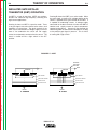
2. To improve consumable life, here are some suggestions that may be useful:
• The nozzle may be dragged on the metal surface, touching it lightly to the surface. NOTE:
The use of a drag cup with the PRO-CUT is
not recommended. The increased standoff
distance reduces the overall performance of
the PRO-CUT.
Return to Master TOC
Return to Section TOC
b. Minimize dross buildup on the nozzle tip by
starting the cut from the edge of the plate when
possible.
d. Reduce the number of pilot arc starts without
transferring to the work.
DRAGthru
thru1/16"
1/16”
DRAG
Standoff
Standoff
e. Reduce the pilot arc time before transferring to
the work.
• Where possible, start the cut from the edge of
the work piece.
• Keep moving! A steady speed is necessary. Do
not pause.
Suggestions for Extra Utility from the
PRO-CUT System:
Return to Master TOC
a. Make sure the air supply to the Pro-Cut is
clean and free of oil. Use several extra in line
filters if necessary.
c. Pierce cutting should be done only when necessary. If piercing, angle torch about 30° from
the plane perpendicular to the work piece,
transfer the arc, then bring the torch perpendicular to the work and begin parallel movement.
Torch Standoff
Return to Section TOC
B-7
WARNING
ELECTRIC SHOCK CAN KILL.
• Turn off machine at the disconnect
switch on the front of the machine
before tightening, cleaning or replacing
consumables.
---------------------------------------------------------------------------PRO-CUT 25
f. Set air pressure to recommended setting. A
higher or lower pressure will cause turbulence
in the plasma arc, eroding the orifice of the
nozzle tip.
g. Use only Lincoln consumable parts. These
parts are patented and using any other
replacement consumables may cause damage
to the torch or reduce cut quality.
Return to Section TOC
Return to Master TOC
Return to Section TOC
Return to Master TOC
Return to Master TOC
Return to Section TOC
Return to Master TOC
Return to Section TOC
B-8
NOTES
PRO-CUT 25
B-8
Section C-1
TABLE OF CONTENTS
- ACCESSORIES Accessories...........................................................................................................................Section C
Options/Accessories...................................................................................................................C-2
Return to Master TOC
Return to Master TOC
Return to Master TOC
Return to Master TOC
Section C-1
PRO-CUT 25
Return to Master TOC
Return to Master TOC
Return to Master TOC
Return to Master TOC
Return to Section TOC
ACCESSORIES
ALWAYS USE GENUINE LINCOLN
ELECTRIC ELECTRODES AND
VORTECH™ NOZZLES
C-2
GENERAL OPTIONS /
ACCESSORIES
The following options/accessories are available for
your PRO-CUT 25 from your local Lincoln Distributor.
• Only Genuine Lincoln Electric consumables yield the
best cutting performance for the PRO-CUT 25.
•
Return to Section TOC
Return to Section TOC
Return to Section TOC
C-2
The patented VORTECH™ nozzle provides an
extra “kick” of swirl as the arc exits the nozzle which
improves cutting performance. No other nozzle has
this capability or can match its performance.
S22147-028 - VORTECH™ nozzle with an .028” (0.7
mm) Orifice
S22149 - Electrode - replacement electrodes for cutting.
S22150 - Shield Cup - This shields the nozzle and provides more visibility to the workpiece. Note the shield
cup does not prevent the torch tip from touching the
workpiece.
K1615 Series - PCT 20 Torches come in 15’ and 25’
lengths. Refer to the Parts Pages in the rear of this
manual for Torch parts.
PRO-CUT 25
Return to Master TOC
Section D-1
Section D-1
TABLE OF CONTENTS
-MAINTENANCEMaintenance .........................................................................................................................Section D
Routine Maintenance..................................................................................................................D-2
Periodic Maintenance .................................................................................................................D-2
Thermal Protection .....................................................................................................................D-2
Replacement Of Internal Fuse....................................................................................................D-2
Return to Master TOC
Return to Master TOC
Return to Master TOC
Major Component Locations .....................................................................................................D-3
PRO-CUT 25
Return to Master TOC
Return to Master TOC
Return to Section TOC
Return to Section TOC
D-2
PERIODIC MAINTENANCE
WARNING
WARNING
ELECTRIC SHOCK can kill.
• Have an electrician install and service
this equipment.
• Turn the input power off at the fuse box
before working on equipment.
• Do not touch electrically hot parts.
• Prior to Performing preventative maintenance, perform the following capacitor discharge procedure to avoid electric shock.
---------------------------------------------------------------------
ELECTRIC SHOCK CAN KILL.
• Turn off machine at the disconnect
switch on the front of the machine
before tightening, cleaning or replacing
consumables.
---------------------------------------------------------------------------Change consumables as required.
ROUTINE MAINTENANCE
Thermal Detection Devices protect the machine from
excessive operating temperatures. Excessive temperatures may be caused by a lack of cooling air or operating the machine beyond the duty cycle and output
rating. If excessive operating temperatures should
occur, the yellow thermal LED will light and the
Detection Devices will prevent output voltage or current.
1. Keep the cutting or gouging area and the area
around the machine clean and free of combustible
materials. No debris should be allowed to collect
which could obstruct air flow to the machine.
2. Every 6 months or so, the machine should be
cleaned with a low pressure airstream. Keeping the
machine clean will result in cooler operation and
higher reliability. Be sure to clean these areas:
- Printed circuit boards and heat sinks
- Power switch
Return to Master TOC
• When using a low pressure aistream, wear
appropiate eye protection.
-----------------------------------------------------------------------3. Examine the sheet metal case for dents or breakage. Repair the case as required. Keep the case in
good condition to insure that high voltage parts are
protected and correct spacings are maintained. All
external sheet metal screws must be in place to
insure case strength and electrical ground continuity.
4. Inspect the cable periodically for any slits or puncture marks in the cable jacket. Replace if necessary. Check to make sure that nothing is crushing
the cable and blocking the flow of air through the air
tube inside. Also, check for kinks in the cable periodically and relieve any so as not to restrict the flow
of air to the torch.
Return to Master TOC
Return to Section TOC
CAUTION
Return to Section TOC
D-2
MAINTENANCE
THERMAL PROTECTION
These Detection Devices are self-resetting once the
machine cools sufficiently. If the thermostat shutdown
was caused by excessive output or duty cycle and the
fan is operating normally, the Power Switch may be left
on and the reset should occur within a 15 minute period. If the fan is not turning or the air intake louvers
were obstructed, then the power must be switched off
and the fan problem or air obstruction must be corrected.
A protection circuit is included to monitor the voltage
across filter capacitors. In the event that the capacitor
voltage is too high, the protection circuit will prevent
output.
REPLACEMENT OF INTERNAL FUSES
The PRO-CUT 25 has additional protection provided to
some circuits through internal fuses. For replacement
of those fuses proceed as follows:
1.
2.
3.
4.
Turn off the power to the unit and remove the input
plug.
Allow the machine to stand for 5 minutes to let the
input capacitors discharge.
Remove the machine cover.
Replace the blown fuse with a new 0.5A 500V
slowblow fuse or 32A 400V fuse as appropriate.
NOTE: If the fuse blows again after power is restored,
the cause could be an internal breakdown in
the power unit. In this case, take the unit to an
authorized Lincoln Field Service Shop.
PRO-CUT 25
Return to Master TOC
Return to Section TOC
D-3
D-3
MAINTENANCE
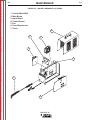
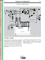
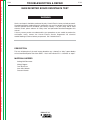
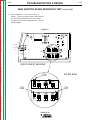
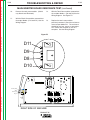
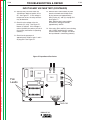
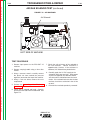
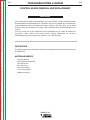
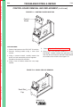
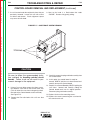
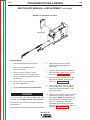
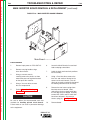
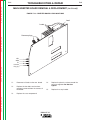
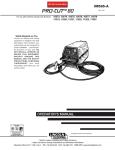
FIGURE D.2 – MAJOR COMPONENT LOCATIONS
1.
2.
3.
4.
5.
6.
7.
Central Metal Wall
Main Board
Input Board
Control Board
Fan
Case Wraparound
Torch
4
Return to Master TOC
Return to Section TOC
6
5
3
R
S PR
ES
SU
RE
TH
PU
ER
MA
L
SA
RG
E
FE
TY
!
20
25
REQU
REQU
IRES
IRES
O
R
20A/1
15V
30A/1
BRAN
15V
CH
BRAN CIRC
CH
UIT
CIRC
UIT
T
U
-C
25
Return to Master TOC
WE
GA
7
PC
Return to Section TOC
PO
F
P
Return to Master TOC
ON
OF
N IC
L R
O T
C EC
IN L
L E
Return to Section TOC
1
T 20
2
PRO-CUT 25
Return to Section TOC
Return to Master TOC
Return to Section TOC
Return to Master TOC
Return to Master TOC
Return to Section TOC
Return to Master TOC
Return to Section TOC
D-4
NOTES
PRO-CUT 25
D-4
Return to Master TOC
Section E-1
Section E-1
TABLE OF CONTENTS
-THEORY OF OPERATION SECTIONTheory of Operation .............................................................................................................Section E
General Description ....................................................................................................................E-2
Input Line Voltage and Auxiliary Transformer .............................................................................E-2
Precharge and Protection ...........................................................................................................E-3
Main Transformer ........................................................................................................................E-4
Output Section and Torch...........................................................................................................E-5
Control Board .............................................................................................................................E-6
Protection Circuits ......................................................................................................................E-7
Return to Master TOC
Overload Protection..............................................................................................................E-7
Thermal Protection ...............................................................................................................E-7
Accidental Operation Protection.................................................................................................E-7
Safety Parts-In-Place Protection ................................................................................................E-7
Insulated Gate Bipolar Transistor (IGBT) Operation ...................................................................E-8
R1
B
FN1
CP
1500uF/250V
R1
R2
AC
RL1
115VAC
V2
+
C1a,b
+
C2a,b
CP
AC
L1
CP
CP
RL2
RL2
V1
230VAC
CP
CP
RL2
10/10W
AC
15K/3W
300uH
AC
RL2
RL3
15K/3W
A
T1
WORK CLAMP
Q1a,b,c
IRG4BC30W
D10
BS1
WRK
8A
PRI
T2
+12VDC TRANSFER
SEC
D11
C12
RL1
NZL (2)
C14
R24
6.8k/5W
Q2a,b,c
IRG4BC30W
SHUNT
C13
230V
EL (3)
SH- SH+
RL1
CN1
115V
L1
Input
Voltage Board
1
2
3
4
5
6
7
8
15VAC
15VAC
SAFETY
+28VDC
SEC GND
OVLOAD
115/230
+12VDC
CN2
9
10
5
6
3
22
2
20
1
2
3
4
12VDC
Main Inverter Board
15 16 12 18 14 1 11 4 13 7 19 24 21 23 8 17
POT_CCW
POT_CW
POT_WIPER
8 6 17 9 3
CN1
1 2 3 4
V_OUT
OUTPUT
TRIGGER
SOL 2 DRIVER
SOL 1 DRIVER
TRANSFER
TRANSFER SW
OVLOAD
SEC GND
+8V_SW
+12VDC_SW
+12VDC
V+
EV1
+15Vrms
SAFETY
SEC GND
OVLOAD
PS1
PS2
NC
COM
NO
CN1
Purge
Switch
Air
Solenoid
1
PT
CN3
1 2 18 14 7 15 4 11 5 16 10 12 13
23 22 24
12VDC
Return to Master TOC
Lout
240uH
1500uF/250V
SW1
F1
Return to Master TOC
C26
L1
1A/250V
INPUT
115/230/1/50/60 VAC
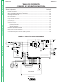
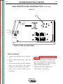
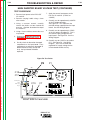
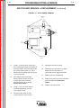
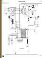
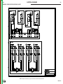
FIGURE E.1 – PRO-CUT 25 BLOCK LOGIC DIAGRAM
Display LED's
Output Control
Control Board
PRO-CUT 25
Solenoid 2
1500uF/250V
C26
A
300uH
R1
B
FN1
CP
CP
RL2
10/10W
RL2
L1
AC
CP
CP
CP
R1
R2
AC
RL1
115VAC
V2
+
C1a,b
+
C2a,b
CP
RL2
AC
V1
230VAC
AC
RL2
RL3
15K/3W
SW1
15K/3W
L1
T1
WORK CLAMP
Q1a,b,c
IRG4BC30W
D10
Lout
BS1
WRK
240uH
8A
PRI
T2
+12VDC TRANSFER
SEC
D11
C12
RL1
NZL (2)
C14
1500uF/250V
INPUT
115/230/1/50/60 VAC
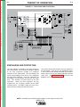
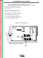
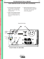
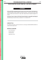
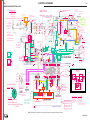
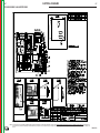
FIGURE E.2 – INPUT LINE VOLTAGE
F1
Return to Master TOC
E-2
THEORY OF OPERATION
1A/250V
Return to Section TOC
E-2
R24
6.8k/5W
Q2a,b,c
IRG4BC30W
SHUNT
C13
230V
EL (3)
SH- SH+
RL1
CN1
115V
15VAC
15VAC
SAFETY
+28VDC
SEC GND
OVLOAD
115/230
+12VDC
CN2
9
10
5
6
3
22
2
20
1
2
3
4
12VDC
Main Inverter Board
Solenoid 2
CN1
1 2 3 4
V_OUT
OUTPUT
TRIGGER
SOL 2 DRIVER
SOL 1 DRIVER
TRANSFER
TRANSFER SW
OVLOAD
SEC GND
+8V_SW
+12VDC_SW
+12VDC
V+
POT_CCW
POT_CW
POT_WIPER
EV1
+15Vrms
SAFETY
SEC GND
OVLOAD
PS1
PS2
8 6 17 9 3
PT
CN3
15 16 12 18 14 1 11 4 13 7 19 24 21 23 8 17
CN1
NC
COM
Return to Master TOC
Input
Voltage Board
NO
Return to Section TOC
L1
1
2
3
4
5
6
7
8
1 2 18 14 7 15 4 11 5 16 10 12 13
23 22 24
12VDC
Purge
Switch
Air
Solenoid
1
Display LED's
Output Control
Return to Section TOC
Return to Master TOC
Return to Section TOC
Return to Master TOC
Control Board
GENERAL DESCRIPTION
The PRO-CUT 25 is an inverter based constant
current, continuous control plasma cutting power
source. The control system has a safety mechanism
to insure that the nozzle and electrode are in place
before cutting or gouging. The PRO-CUT 25 initiates
the plasma arc with a simple, yet reliable, touch start
mechanism. This system eliminates many of the problems associated with hi-frequency type start systems.
INPUT LINE VOLTAGE, AND
AUXILIARY TRANSFORMER
The single-phase input power of 115 230 Volts AC is
connected to the machine, via an input cord, to a
switch located on the front panel.
The PRO-CUT 25 Input voltage board automatically
reconnects the auxiliary and inverter connections to
configure the machine for either a low 115V AC or high
230V AC input voltage. The auxiliary transformer
develops the appropriate AC voltages to operate the
cooling fan, the control board, and the inverter board.
NOTE: Unshaded areas of Block Logic Diagram are the subject of discussion.
PRO-CUT 25
1500uF/250V
C26
A
300uH
R1
B
FN1
CP
CP
RL2
10/10W
CP
CP
CP
R1
R2
AC
RL1
115VAC
V2
+
C1a,b
+
C2a,b
CP
AC
L1
AC
RL2
RL2
V1
230VAC
AC
RL2
RL3
15K/3W
SW1
15K/3W
L1
T1
WORK CLAMP
Q1a,b,c
IRG4BC30W
D10
Lout
BS1
WRK
240uH
8A
PRI
T2
+12VDC TRANSFER
SEC
D11
C12
RL1
NZL (2)
C14
1500uF/250V
INPUT
115/230/1/50/60 VAC
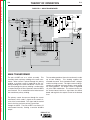
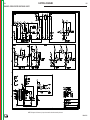
FIGURE E.3 – PRECHARGE AND PROTECTION
F1
Return to Master TOC
E-3
THEORY OF OPERATION
1A/250V
Return to Section TOC
E-3
R24
6.8k/5W
Q2a,b,c
IRG4BC30W
SHUNT
C13
230V
EL (3)
SH- SH+
RL1
CN1
115V
15VAC
15VAC
SAFETY
+28VDC
SEC GND
OVLOAD
115/230
+12VDC
CN2
9
10
5
6
3
22
2
20
1
2
3
4
12VDC
Main Inverter Board
Solenoid 2
CN1
1 2 3 4
V_OUT
OUTPUT
TRIGGER
SOL 2 DRIVER
SOL 1 DRIVER
TRANSFER
TRANSFER SW
OVLOAD
SEC GND
+8V_SW
+12VDC_SW
+12VDC
V+
POT_CCW
POT_CW
POT_WIPER
EV1
+15Vrms
SAFETY
SEC GND
OVLOAD
PS1
PS2
8 6 17 9 3
PT
CN3
15 16 12 18 14 1 11 4 13 7 19 24 21 23 8 17
CN1
NC
COM
Return to Master TOC
Input
Voltage Board
NO
Return to Section TOC
L1
1
2
3
4
5
6
7
8
1 2 18 14 7 15 4 11 5 16 10 12 13
23 22 24
12VDC
Purge
Switch
Air
Solenoid
1
Display LED's
Output Control
Return to Section TOC
Return to Master TOC
Return to Section TOC
Return to Master TOC
Control Board
PRECHARGE AND PROTECTION
The input voltage is rectified by the input rectifier on
the inverter board. The resultant DC voltage is applied
to the filter capacitors through the automatic
reconnect of the input board. The input board also
contains precharging circuitry for the safe charging of
the input filter capacitors. Once the capacitors are
precharged the input board activates the RL3 input
relay. This connects full input power to the filter
capacitors. When the filter capacitors are fully
charged they act as power supplies for the IGBT
switching circuit. The IGBTs supply the main transformer primary winding with DC current flow.
The inverter board also monitors the filter capacitors
for overvoltage. If this occurs, the appropriate signal
is sent to the control board to disable the machines
output and to turn on the Thermal/Voltage Overload
status LED. See IGBT Operation discussion and
diagrams in this section.
NOTE: Unshaded areas of Block Logic Diagram are the subject of discussion.
PRO-CUT 25
1500uF/250V
C26
A
300uH
R1
B
FN1
CP
CP
RL2
10/10W
RL2
L1
AC
CP
CP
CP
R1
R2
AC
RL1
115VAC
V2
+
C1a,b
+
C2a,b
CP
RL2
AC
V1
230VAC
AC
RL2
RL3
15K/3W
SW1
15K/3W
L1
T1
WORK CLAMP
Q1a,b,c
IRG4BC30W
D10
Lout
BS1
WRK
240uH
8A
PRI
T2
+12VDC TRANSFER
SEC
D11
C12
RL1
NZL (2)
C14
1500uF/250V
INPUT
115/230/1/50/60 VAC
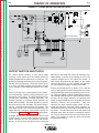
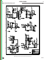
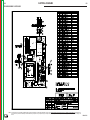
FIGURE E.4 – MAIN TRANSFORMER
F1
Return to Master TOC
E-4
THEORY OF OPERATION
1A/250V
Return to Section TOC
E-4
R24
6.8k/5W
Q2a,b,c
IRG4BC30W
SHUNT
C13
230V
EL (3)
SH- SH+
RL1
CN1
Input
Voltage Board
1
2
3
4
5
6
7
8
15VAC
15VAC
SAFETY
+28VDC
SEC GND
OVLOAD
115/230
+12VDC
CN2
9
10
5
6
3
22
2
20
1
2
3
4
12VDC
Main Inverter Board
Solenoid 2
CN1
1 2 3 4
V_OUT
OUTPUT
TRIGGER
SOL 2 DRIVER
SOL 1 DRIVER
TRANSFER
TRANSFER SW
OVLOAD
SEC GND
+8V_SW
+12VDC_SW
+12VDC
V+
POT_CCW
POT_CW
POT_WIPER
EV1
+15Vrms
SAFETY
SEC GND
OVLOAD
PS1
PS2
8 6 17 9 3
PT
CN3
15 16 12 18 14 1 11 4 13 7 19 24 21 23 8 17
CN1
NC
COM
Return to Master TOC
L1
NO
Return to Section TOC
115V
1 2 18 14 7 15 4 11 5 16 10 12 13
23 22 24
12VDC
Purge
Switch
Air
Solenoid
1
Display LED's
Output Control
Return to Section TOC
Return to Master TOC
Return to Section TOC
Return to Master TOC
Control Board
MAIN TRANSFORMER
The pair of IGBTs act as a switch assembly. This
assembly feeds a primary winding of the main transformer. When current is pulsed through this primary
winding, a resultant current is produced on the secondary winding of the main transformer. The DC current flow through the primary winding is redirected or
“clamped” back to the filter capacitors when the IGBTs
are turned off. This is needed due to the inductance of
the transformer primary winding.
The secondary portion of the main transformer is made
up of one winding. This winding supplies the
electrode-to-nozzle and electrode-to-work voltages
and the resulting currents. This high current winding is
capable of supplying maximum output current during
the cutting process. The output current is regulated
via pulse width modulation. The control circuitry, on
the inverter board, receives a signal from the control
board and regulates the output current to the desired
level.
The primary current also passes through the current
transformer, which sends a signal to the control circuits of the inverter board. This signal and the control
circuits limit the maximum primary current flow
through the IGBTs. The pair of IGBT’s are fired at 15
microsecond intervals, creating a constant 66.6KHz
output.
PRO-CUT 25
1500uF/250V
C26
A
300uH
R1
B
FN1
CP
CP
RL2
10/10W
RL2
L1
AC
CP
CP
CP
R1
R2
AC
RL1
115VAC
V2
+
C1a,b
+
C2a,b
CP
RL2
AC
V1
230VAC
AC
RL2
RL3
15K/3W
SW1
15K/3W
L1
T1
WORK CLAMP
Q1a,b,c
IRG4BC30W
D10
Lout
BS1
WRK
240uH
8A
PRI
T2
+12VDC TRANSFER
SEC
D11
C12
RL1
NZL (2)
C14
1500uF/250V
INPUT
115/230/1/50/60 VAC
FIGURE E.5 – PLASMA OUTPUT SECTION AND TORCH
F1
Return to Master TOC
E-5
THEORY OF OPERATION
1A/250V
Return to Section TOC
E-5
R24
6.8k/5W
Q2a,b,c
IRG4BC30W
SHUNT
C13
230V
EL (3)
SH- SH+
RL1
CN1
115V
L1
1
2
3
4
12VDC
Main Inverter Board
Solenoid 2
CN1
1 2 3 4
POT_CCW
POT_CW
POT_WIPER
8 6 17 9 3
PT
CN3
V_OUT
OUTPUT
TRIGGER
SOL 2 DRIVER
SOL 1 DRIVER
TRANSFER
TRANSFER SW
OVLOAD
SEC GND
+8V_SW
+12VDC_SW
+12VDC
V+
EV1
+15Vrms
SAFETY
SEC GND
OVLOAD
PS1
PS2
Return to Master TOC
CN2
9
10
5
6
3
22
2
20
15VAC
15VAC
SAFETY
+28VDC
SEC GND
OVLOAD
115/230
+12VDC
15 16 12 18 14 1 11 4 13 7 19 24 21 23 8 17
CN1
NC
COM
NO
Return to Section TOC
Input
Voltage Board
1
2
3
4
5
6
7
8
1 2 18 14 7 15 4 11 5 16 10 12 13
23 22 24
12VDC
Purge
Switch
Air
Solenoid
1
Display LED's
Output Control
Control Board
Return to Master TOC
Return to Master TOC
Return to Section TOC
Return to Section TOC
OUTPUT SECTION AND TORCH
The output section contains a relay which, upon
receiving a pilot signal from the control board will
enable the operation of a pilot arc or a cutting arc. The
printed circuit board mounted current sensor regulates
the pilot and cutting current. The output choke, which
is in series with both the pilot circuit and the cutting
circuit, provides current filtering to enhance arc stability.
The PCT 20 torch uses a patented touch start mechanism that provides superior starting performance over
other touch start systems. The torch head consists of
3 major parts: torch body, insulator and piston. The
insulator provides an electrical barrier between the
piston and torch body. The piston provides a path for
electrical current to the electrode. The piston also drives the electrode to the nozzle for arc initiation. The
torch body contains the main torch components: the
trigger, pilot arc, cutting arc, and air flow systems are
included. See Figure F.10 & G Section for more detail.
A copper nozzle with a patented internal swirl is used
to focus the arc. A small, precise hole in the end of the
nozzle constricts the arc and increases the current
density. As the air enters the torch head, it is directed
between the electrode and nozzle for maximum electrode cooling. A portion of the cooling air exits in the
chamber through vents in the side of the nozzle. A
swirl texture located inside the bottom of the nozzle
increases the plenum air swirl strength, and improves
arc start reliability and parts-in-place verification.
Plasma arc initiation occurs as follows: First, in the idle
state, a spring inside the torch head pushes the piston
and electrode forward to make continuity with the nozzle. When the trigger is pulled, air flow begins and creates enough back force on the electrode to overcome
the force of the spring. However, the solenoid valve
allows enough forward force on the piston to maintain
continuity between the consumables. After this
continuity has been verified, output current is established and regulated. Once the current stabilizes, the
solenoid valve turns off, removing the forward force on
the piston. The back pressure drives the piston and
electrode away from the nozzle, creating the plasma
arc. The air stream forces the arc out the orifice of the
nozzle. This appears as a pilot arc, which can then be
transferred for cutting.
PRO-CUT 25
E-6
THEORY OF OPERATION
1500uF/250V
FIGURE E.6 – CONTROL BOARD
C26
300uH
R1
B
F1
FN1
CP
CP
RL2
10/10W
RL2
L1
AC
CP
CP
CP
R1
R2
AC
RL1
115VAC
V2
+
C1a,b
+
C2a,b
CP
RL2
AC
V1
230VAC
AC
RL2
RL3
15K/3W
A
15K/3W
SW1
T1
WORK CLAMP
Q1a,b,c
IRG4BC30W
D10
Lout
BS1
WRK
240uH
8A
PRI
T2
+12VDC TRANSFER
SEC
D11
C12
RL1
NZL (2)
C14
1500uF/250V
L1
1A/250V
INPUT
115/230/1/50/60 VAC
Return to Master TOC
Return to Section TOC
E-6
R24
6.8k/5W
Q2a,b,c
IRG4BC30W
SHUNT
C13
230V
EL (3)
SH- SH+
RL1
CN1
Input
Voltage Board
15VAC
15VAC
SAFETY
+28VDC
SEC GND
OVLOAD
115/230
+12VDC
CN2
9
10
5
6
3
22
2
20
1
2
3
4
12VDC
Main Inverter Board
15 16 12 18 14 1 11 4 13 7 19 24 21 23 8 17
8 6 17 9 3
Solenoid 2
CN1
1 2 3 4
POT_CCW
POT_CW
POT_WIPER
EV1
+15Vrms
NC
COM
NO
CN1
PT
CN3
V_OUT
OUTPUT
TRIGGER
SOL 2 DRIVER
SOL 1 DRIVER
TRANSFER
TRANSFER SW
OVLOAD
SEC GND
+8V_SW
+12VDC_SW
+12VDC
V+
Return to Master TOC
L1
1
2
3
4
5
6
7
8
SAFETY
SEC GND
OVLOAD
PS1
PS2
Return to Section TOC
115V
1 2 18 14 7 15 4 11 5 16 10 12 13
23 22 24
12VDC
Purge
Switch
Air
Solenoid
1
Display LED's
Output Control
Return to Section TOC
Return to Master TOC
Return to Section TOC
Return to Master TOC
Control Board
CONTROL BOARD
The control board receives status and analog
feedback signals from the inverter board, input board,
and various sensors. The control circuitry interprets
these signals, makes decisions and changes the
machines mode and output to satisfy the requirements
as defined by the circuitry. The control board sends a
signal to the inverter board to control the output
current but the actual regulation circuits are on the
inverter board.
The display board, directly connected to the control
board, communicates PRO-CUT 25 status and
operating conditions to the user. There are four status
indicators: Power On, Gas Pressure, Thermal
Overload, and Safety Error.
PRO-CUT 25
Return to Master TOC
Return to Master TOC
Return to Master TOC
Return to Master TOC
Return to Section TOC
Return to Section TOC
Return to Section TOC
Return to Section TOC
E-7
THEORY OF OPERATION
PROTECTION CIRCUITS
Protection circuits are designed into the PRO-CUT 25
machine to sense trouble, damages, problems with
internal components, and to provide safety. These are
the main protection circuits:
OVERLOAD PROTECTION
The PRO-CUT 25 is electrically protected from
producing higher than normal output currents. If the
output current exceeds 25-30 amps, an electronic
protection circuit limits the current to within the
capabilities of the machine. A second circuit monitors
the input voltage and the voltage across the input filter
capacitors. If the input voltage or filter capacitor
voltage is too high, or too low, the protection circuit
will prevent machine output.
THERMAL PROTECTION
Three thermal protection devices protect the machine
from excessive operating temperatures. One device
is located on the output choke, one is located inside
the main transformer, and another is mounted on one
of the IGBT heat sinks. Excessive temperatures may
be caused by a lack of cooling air or by operating the
machine beyond the duty cycle and output rating. If
excessive operating temperatures should occur, the
thermal status indicator will turn on and the thermostat
will prevent output voltage or current. The thermal
protection devices are self-resetting once the machine
cools sufficiently. If the shutdown was caused by
excessive output or duty cycle and the fans are
operating normally, the power switch may be left on
and the reset should occur within a 15 minute period.
If the fan is not turning or the air intake louvers are
obstructed, the input power must be removed and the
fan problem or air obstruction must be corrected.
After a thermal overload occurs and the machine
resets, it may be necessary to activate the torch
trigger twice before a pilot arc will be initiated. This is
a safety precaution, to eliminate accidental pilot arc
initiation when the thermal protection self resets.
E-7
ACCIDENTAL OPERATION
PROTECTION
The PRO-CUT 25 has two protection circuits to
eliminate accidental pilot arc initiation. These two
circuits operate when the machine is first turned on
and after a thermal overload occurs. In these cases,
the first time the torch trigger is activated nothing will
happen. The torch trigger must be activated a second
time before pilot arc initiation occurs. This protection
is added in case the machine is turned on and the trigger is already activated or if a thermal overload self
resets and the trigger is activated.
SAFETY PARTS-IN-PLACE
PROTECTION
The PRO-CUT 25 has protection circuits to detect the
proper connection of the torch and the proper
installation of the consumables. If an error is detected
with either of these two items, the Safety status LED
will be turned on and the output of the machine will be
disabled. The PRO-CUT 25 must be turned off and
the problem must be corrected before normal
operation can occur.
PRO-CUT 25
THEORY OF OPERATION
Return to Section TOC
Return to Master TOC
Return to Section TOC
Return to Master TOC
E-8
E-8
INSULATED GATE BIPOLAR
TRANSISTOR (IGBT) OPERATION
An IGBT is a type of transistor. IGBTs are semiconductors well suited for high frequency switching and
high current applications.
Drawing A shows an IGBT in a passive mode. There
is no gate signal, zero volts relative to the source, and
therefore, no current flow. The drain terminal of the
IGBT may be connected to a voltage supply; but since
there is no conduction the circuit will not supply
current to components connected to the source. The
circuit is turned off like a light switch in the OFF
position.
Drawing B shows the IGBT in an active mode. When
the gate signal, a positive DC voltage relative to the
source, is applied to the gate terminal of the IGBT, it
is capable of conducting current. A voltage supply
connected to the drain terminal will allow the IGBT to
conduct and supply current to circuit components
coupled to the source. Current will flow through the
conducting IGBT to downstream components as long
as the positive gate signal is present. This is similar
to turning ON a light switch.
FIGURE E.5 – IGBT
POSITIVE
VOLTAGE
APPLIED
Return to Master TOC
Return to Section TOC
SOURCE
n+
GATE
SOURCE
n+
n+
Return to Master TOC
n+
p
BODY REGION
p
BODY REGION
n-
DRAIN DRIFT REGION
n-
DRAIN DRIFT REGION
n+
BUFFER LAYER
n+
BUFFER LAYER
p+
INJECTING LAYER
p+
INJECTING LAYER
DRAIN
DRAIN
B. ACTIVE
A. PASSIVE
Return to Section TOC
GATE
PRO-CUT 25
Return to Master TOC
Section F-1
Section F-1
TABLE OF CONTENTS
TROUBLESHOOTING & REPAIR SECTION
Troubleshooting & Repair Section .................................................................................Section F
How to Use Troubleshooting Guide ....................................................................................F-2
PC Board Troubleshooting Procedures and Replacement .................................................F-3
Troubleshooting Guide ........................................................................................................F-4
Replacement Procedures
Control Board Removal and Replacement ...................................................................F-31
Input Board Removal and Replacement.......................................................................F-35
Main Inverter Board Removal and Replacement ..........................................................F-39
Switch Removal and Replacement ...............................................................................F-43
Fan Removal and Replacement ....................................................................................F-45
Retest after Repair ........................................................................................................F-48
Return to Master TOC
Return to Master TOC
Return to Master TOC
Test Procedures
Input Filter Capacitor Discharge Procedure .................................................................F-9
Main Inverter Board Resistance Test ............................................................................F-11
Input Board Voltage Test ...............................................................................................F-17
Main Inverter Board Voltage Test ..................................................................................F-21
Torch Continuity and Solenoid Test ..............................................................................F-25
Air/Gas Solenoid Test....................................................................................................F-29
PRO-CUT 25
Return to Master TOC
Return to Master TOC
Return to Master TOC
Return to Section TOC
Return to Section TOC
Return to Section TOC
F-2
TROUBLESHOOTING & REPAIR
HOW TO USE TROUBLESHOOTING GUIDE
CAUTION
Service and repair should be performed by only Lincoln Electric Factory Trained Personnel.
Unauthorized repairs performed on this equipment may result in danger to the technician and machine
operator and will invalidate your factory warranty. For your safety and to avoid Electrical Shock, please
observe all safety notes and precautions detailed throughout this manual.
This Troubleshooting Guide is provided to help
you locate and repair possible machine
malfunctions. Simply follow the three-step
procedure listed below.
Step 1. LOCATE PROBLEM (SYMPTOM). Look
under the column labeled “PROBLEM
(SYMPTOMS)”. This column describes possible
symptoms that the machine may exhibit. Find
the listing that best describes the symptom that
the machine is exhibiting. Symptoms are
grouped into three main categories: Output
Problems, Function Problems, and LED Function
Problems.
Step 2. PERFORM EXTERNAL TESTS. The
second column, labeled “POSSIBLE AREAS OF
MISADJUSTMENT(S)”, lists the obvious external
possibilities that may contribute to the machine
symptom. Perform these tests/checks in the
order listed. In general, these tests can be
conducted without removing the case
wrap-around cover.
Step 3. PERFORM COMPONENT TESTS. The
last column, labeled “Recommended Course of
Action” lists the most likely components that may
have failed in your machine. It also specifies the
appropriate test procedure to verify that the
subject component is either good or bad. If there
are a number of possible components, check the
components in the order listed to eliminate one
possibility at a time until you locate the cause of
your problem.
All of the referenced test procedures referred to in
the Troubleshooting Guide are described in detail
at the end of this chapter. Refer to the
Troubleshooting and Repair Table of Contents to
locate each specific Test Procedure. All of the
referred to test points, components, terminal
strips, etc., can be found on the referenced
electrical wiring diagrams and schematics. Refer
to the Electrical Diagrams Section Table of
Contents to locate the appropriate diagram.
Return to Master TOC
Return to Section TOC
CAUTION
If for any reason you do not understand the test procedures or are unable to perform the test/repairs
safely, contact the Lincoln Electric Service Department for electrical troubleshooting assistance before
you proceed. Call 1-888-935-3877
PRO-CUT 25
F-2
TROUBLESHOOTING & REPAIR
Return to Master TOC
Return to Master TOC
Return to Section TOC
Return to Section TOC
F-3
PC BOARD TROUBLESHOOTING PROCEDURES
WARNING
ELECTRIC SHOCK can kill.
Have an electrician install and service
this equipment. Turn the machine OFF
before working on equipment. Do not
touch electrically hot parts.
Sometimes machine failures appear to be due to PC
board failures. These problems can sometimes be
traced to poor electrical connections. To avoid problems when troubleshooting and replacing PC boards,
please use the following procedure:
Return to Master TOC
Return to Section TOC
• If the PC Board uses protective shorting jumpers,
don’t remove them until installation is complete.
• If you return a PC Board to The Lincoln Electric
Company for credit, it must be in the static-shielding
bag. This will prevent further damage and allow
proper failure analysis.
4. Test the machine to determine if the failure symptom has been corrected by the replacement PC
board.
NOTE: Allow the machine to heat up so that all
electrical components can reach their
operating temperature.
2. Check for loose connections at the PC board to
assure that the PC board is properly connected.
5. Remove the replacement PC board and substitute
it with the original PC board to recreate the original
problem.
a. If the original problem does not reappear
by substituting the original board, then the
PC board was not the problem. Continue
to look for bad connections in the control
wiring harness, junction blocks, and terminal strips.
PC Board can be damaged by
static electricity.
ATTENTION
Static-Sensitive
Devices
Handle only at
Static-Safe
Workstations
Reusable
Container
Do Not Destroy
Return to Master TOC
• Remove the PC Board from the static-shielding bag
and place it directly into the equipment. Don’t set
the PC Board on or near paper, plastic or cloth which
could have a static charge. If the PC Board can’t be
installed immediately, put it back in the staticshielding bag.
1. Determine to the best of your technical ability that
the PC board is the most likely component causing the failure symptom.
3. If the problem persists, replace the suspect PC
board using standard practices to avoid static
electrical damage and electrical shock. Read the
warning inside the static resistant bag and perform
the following procedures:
Return to Section TOC
F-3
• Remove your body’s static
charge before opening the staticshielding bag. Wear an anti-static wrist strap. For safety, use a
1 Meg ohm resistive cord connected to a grounded part of the
equipment frame.
• If you don’t have a wrist strap,
touch an unpainted, grounded,
part of the equipment frame.
Keep touching the frame to
prevent static build-up. Be sure
not to touch any electrically live
parts at the same time.
b. If the original problem is recreated by the
substitution of the original board, then the
PC board was the problem. Reinstall the
replacement PC board and test the
machine.
6. Always indicate that this procedure was followed
when warranty reports are to be submitted.
NOTE: Following this procedure and writing on the
warranty report, “INSTALLED AND SWITCHED
PC BOARDS TO VERIFY PROBLEM,” will help
avoid denial of legitimate PC board warranty
claims.
• Tools which come in contact with the PC Board must
be either conductive, anti-static or static-dissipative.
PRO-CUT 25
Return to Master TOC
TROUBLESHOOTING & REPAIR
PROBLEMS
(SYMPTOMS)
F-4
TROUBLESHOOTING GUIDE
Observe Safety Guidelines
detailed in the beginning of this manual.
POSSIBLE AREAS OF
MISADJUSTMENT(S)
RECOMMENDED
COURSE OF ACTION
OUTPUT PROBLEMS
Major physical or electrical damage is evident when the sheet
metal cover(s) are removed.
1. Contact your local authorized
Lincoln Electric Field Service
Facility for technical assistance.
1. Contact the Lincoln Electric
Service Department,
Machine is dead – no output – no
fan – no status indicator lights.
1. Make sure that the input power
switch is in the “ON” position.
1. Check the input power switch
for proper operation.
2. Check the input voltage at the
machine. Input voltage must
match the rating plate.
2. Check the leads associated
with the power switch for loose
or faulty connections. See the
Wiring Diagram.
Return to Master TOC
Return to Section TOC
Return to Section TOC
F-4
3. Check for blown or missing
fuses in the input lines and the
1A slow blow fuse on the input
board.
Machine is malfunctioning - no
output - no status indicator lights fans run.
1. Check the input voltage at the
machine. Input voltage must
match the rating plate.
1-888-935-3877
3. Check all connectors and wires
for loose or faulty connections.
4. Perform the Input Voltage
Board Test.
1. Check all connectors and wires
for loose or faulty connections.
See Wiring Diagram.
Return to Section TOC
Return to Master TOC
Return to Section TOC
Return to Master TOC
2. Perform the Input Voltage
Board Test.
3. The control board may be
faulty. Replace.
CAUTION
If for any reason you do not understand the test procedures or are unable to perform the test/repairs safely, contact the Lincoln Electric Service Department for electrical troubleshooting assistance before you proceed. Call
1-888-935-3877.
PRO-CUT 25
Return to Master TOC
Return to Master TOC
Return to Master TOC
Return to Section TOC
Return to Section TOC
Return to Section TOC
F-5
TROUBLESHOOTING & REPAIR
TROUBLESHOOTING GUIDE
PROBLEMS
(SYMPTOMS)
Observe Safety Guidelines
detailed in the beginning of this manual.
POSSIBLE AREAS OF
MISADJUSTMENT(S)
Return to Master TOC
RECOMMENDED
COURSE OF ACTION
FUNCTION PROBLEMS
The machine powers up properly,
but there is no response (no air flow
or pilot arc) when the torch trigger
is pulled. Only the power LED is lit.
1. Make sure the torch handle or
cable is not damaged or pulled
from the machine. Replace if
necessary.
The machine powers up properly,
but only air flows when the torch
trigger is pulled; no pilot arc is
established.
2. Make sure the air supply is
converted and operating
properly.
1. Make sure the torch consumables are in place and in good
condition. Replace if necessary.
2. Set air pressure at 65psi.
1. Check all connectors and wires
for loose or faulty connections.
See Wiring Diagram.
2. Perform the Air/Gas
Solenoid Test.
3. The control board may be
faulty. Replace.
1. Check all connectors and wires
for loose or faulty connections.
See Wiring Diagram.
2
Perform the Torch Continuity
and Solenoid Test.
3. Make sure there are no kinks or
restrictions for air flow in the
torch cable.
3. Perform the Main Inverter
Board Voltage and
Resistance Tests.
4. Make sure that the correct size
nozzle is being used. Must be a
.028 orifice. Pro-Cut 55 size
nozzles will not work with the
Pro-Cut 25 system.
4. The control board may be
faulty. Replace.
The machine powers up properly,
and cuts OK with 230 input
applied. With 115 applied the pilot
arc ignites but goes out when cutting commences. Or, no pilot or
cutting when 115 input is supplied.
1. CP leads to its terminal from the
input to the inverter board are
loose or disconnected.
1. Reconnect the leads to its correct terminal per the wiring diagram.
The air begins to flow when the
torch trigger is pulled. There is a
very brief pilot arc. (Normal is 3
Seconds.) The sequence is repeated with subsequent trigger pulls.
1. Check the input voltage at the
machine. Input voltage must
match the rating plate.
1. Check all connectors and wires
for loose or faulty connections.
See Wiring Diagram.
2. Make sure the torch
consumable parts are in place
and in good condition.
Replace if necessary.
2. Perform the Main Inverter
Board Voltage and
Resistance Tests.
2. Perform the Input Board Test.
3. The input board may be faulty.
Replace.
3. Make sure there are no kinks or
restrictions for air flow in the
torch cable.
Return to Section TOC
F-5
4. Make sure the air pressure is
set at 65psi.
5. Make sure that the correct size
nozzle is being used. Must be a
.028 orifice. Pro-Cut 55 size
nozzles will not work with the
PC 25 system.
PRO-CUT 25
3. The control board may be
faulty. Replace.
Return to Master TOC
Return to Section TOC
F-6
TROUBLESHOOTING & REPAIR
TROUBLESHOOTING GUIDE
Observe Safety Guidelines
detailed in the beginning of this manual.
PROBLEMS
(SYMPTOMS)
POSSIBLE AREAS OF
MISADJUSTMENT(S)
The cutting arc starts but sputters
badly.
1. Make sure the operating procedure is correct for the process.
See the Operation section of
the manual.
Return to Master TOC
Return to Section TOC
3. Make sure the torch consumable parts are in place and in
good condition. Replace if
necessary.
4. Make sure the air pressure is
set at 65psi.
The pilot arc is normal, but the arc
will not transfer to the work piece.
1. Make sure the operating
procedure is correct for the
process. See the Operation
section of the manual.
Return to Master TOC
3. The work piece must be electrically conductive material, and
the work clamp must make a
good electrical connection with
the work piece.
2. Perform the Torch Continuity
and Solenoid Test.
3. Perform the Main Inverter
Board Voltage and Resistance
Tests.
4. The control board may be
faulty. Replace.
5. Use the correct extension cord.
See the instruction manual.
1. Check all connectors and
wires for loose or faulty connections. See Wiring Diagram.
2. Perform the Main Inverter
Board Voltage and Resistance
Tests.
3. The control board may be
faulty. Replace.
4. Do not use a drag cup. Not
recommended for Pro-Cut 25
use.
Trigger or purge is activated brief
air flow then the safety light illuminates.
Poor performance of pilot arc or
cutting. Poor consumable life.
Return to Master TOC
1. Check all connectors and
wires for loose or faulty connections. See Wiring Diagram.
5. Make sure the air supply is not
contaminated with oil or
excessive water.
2. Make sure the work clamp is
connected tightly to the work
piece.
Return to Section TOC
RECOMMENDED
COURSE OF ACTION
FUNCTION PROBLEMS
2. Make sure the work clamp is
connected tightly to the work
piece.
Return to Section TOC
F-6
1. The Control Board is defective.
Replace.
1. Check pressure switch to be
functioning
correctly
(opening/closing) at its correct
pressure.
2. Check pressure gauge to be
correct in its reading.
3. Check for recommended flow
rate coming from the torch end
with a flow meter.
PRO-CUT 25
1. Try increasing or decreasing the
air pressure to see if conditions
improve.
2. Replace regulator or pressure
switch may be required.
3. Screen in air line at inlet to air
solenoid may be clogged.
Clean. (no screen before 7/1/02)
4. Ensure that air is clean and dry
External filters may be used.
Return to Master TOC
TROUBLESHOOTING & REPAIR
F-7
Observe Safety Guidelines
detailed in the beginning of this manual.
TROUBLESHOOTING GUIDE
PROBLEMS
(SYMPTOMS)
RECOMMENDED
COURSE OF ACTION
POSSIBLE AREAS OF
MISADJUSTMENT(S)
FUNCTION PROBLEMS
Will only cut thin gauge material or
cutting cutting is 1/2 of what it
should be. Cuts for 3 seconds
then quits.
The ground lead or clamp is disconnected. Unit is not transferring
to cut mode.
1. Replace or repair, clamp or
cable.
2. Clamp directly to the piece to
be cut.
3. Look for the transfer signal from
the inverter board to the control
Board per the enhanced diagram.
Return to Master TOC
Return to Section TOC
Return to Section TOC
F-7
4. Possible replacement of the
inverter board per the signal of
the enhanced diagram.
5. Possible replacement of the
Control Board per the signal of
the enhanced diagram.
6. Use the correct extension cord.
See the instruction manual.
Return to Section TOC
Return to Master TOC
Return to Section TOC
Return to Master TOC
When nothing is described for your
problem, or you have performed
your test with no solution.
1. Unplug and re-plug in all the
printed circuit board harness
connectors.
CAUTION
If for any reason you do not understand the test procedures or are unable to perform the test/repairs safely, contact the Lincoln Electric Service Department for electrical troubleshooting assistance before you proceed.
Call 1-888-935-3877.
PRO-CUT 25
Return to Master TOC
Return to Section TOC
F-8
TROUBLESHOOTING & REPAIR
Observe Safety Guidelines
detailed in the beginning of this manual.
TROUBLESHOOTING GUIDE
PROBLEMS
(SYMPTOMS)
RECOMMENDED
COURSE OF ACTION
Return to Master TOC
Return to Master TOC
Return to Master TOC
Return to Section TOC
Return to Section TOC
POSSIBLE AREAS OF
MISADJUSTMENT(S)
LED FUNCTION PROBLEMS
The Thermal LED is lit after normal
use.
Return to Section TOC
F-8
1. One of the machine’s thermal
protection circuits has tripped.
Do not turn the PRO-CUT 25 off.
Allow the machine to cool. The
thermal protection circuits will
reset themselves.
2. Either the duty cycle has been
exceeded, the fan is not functioning, or the louvers are
blocked.
1. Check all connectors and wires
for loose or faulty connections.
See Wiring Diagram.
2. The inverter board may be
faulty. Replace.
3. The control board may be faulty.
Replace.
4. Use the correct extension cord.
See the instruction manual.
3. Thermo light comes on when
over voltage occurs +/-10%
must be with in 10%.
CAUTION
If for any reason you do not understand the test procedures or are unable to perform the test/repairs safely, contact the Lincoln Electric Service Department for electrical troubleshooting assistance before you proceed.
Call 1-888-935-3877.
PRO-CUT 25
TROUBLESHOOTING & REPAIR
Return to Master TOC
Return to Section TOC
F-9
INPUT FILTER CAPACITOR DISCHARGE PROCEDURE
WARNING
Service and repair should be performed by only Lincoln Electric factory trained
personnel. Unauthorized repairs performed on this equipment may result in danger to
the technician or machine operator and will invalidate your factory warranty. For your
safety and to avoid electrical shock, please observe all safety notes and precautions
detailed throughout this manual.
Return to Master TOC
Return to Section TOC
If for any reason you do not understand the test procedures or are unable to perform the
test/repairs safely, contact the Lincoln Electric Service Department for electrical
troubleshooting assistance before you proceed. Call 1-888-935-3877.
DESCRIPTION
This procedure will drain off any charge stored in the four capacitors that are part of the
Inverter Board assembly. This procedure MUST be performed, as a safety precaution,
before conducting any test or repair procedure that requires you to touch internal
components of the machine.
Return to Section TOC
Return to Master TOC
Return to Section TOC
Return to Master TOC
MATERIALS NEEDED
4mm Allen Wrench
Volt/Ohmmeter
7mm Nut Driver
Crescent Wrench
Insulated Gloves
Insulated Pliers
High Wattage Resistor - 25 to 1000 ohms, 25 watts minimum
PRO-CUT 25
F-9
Return to Master TOC
Return to Section TOC
F-10
INPUT FILTER CAPACITOR DISCHARGE PROCEDURE (continued)
5. Be careful not to make contact with the capacitor
terminals located at the top of the main inverter
Board.
WARNING
ELECTRIC SHOCK can kill.
• Have an electrician install and service
this equipment.
• Turn the input power off at the fuse box
before working on equipment.
Return to Master TOC
• Do not touch electrically hot parts.
Return to Section TOC
F-10
TROUBLESHOOTING & REPAIR
• Prior to performing preventative maintenance,
perform the following capacitor discharge procedure
to avoid electric shock.
DISCHARGE PROCEDURE
1. Remove input power to the PRO-CUT 25 machine.
2. Remove carrying handle using a 4mm allen
wrench.
3. Using a crescent wrench, carefully remove the
plastic nut from around the pressure regulator
located on the top of the machine.
6. Obtain a high resistance and high wattage resistor
(25-1000 ohms and 25 watts minimum). This
resistor is not supplied with machine. NEVER USE
A SHORTING STRAP FOR THIS PROCEDURE.
7. Locate the eight capacitor terminals located at the
top rear of the main inverter board. See Figure F.1
8. Use electrically insulated gloves and insulated pliers. Hold the body of the resistor and connect the
resistor leads across the two capacitor terminals.
Hold the resistor in place for 10 seconds. DO NOT
TOUCH CAPACITOR TERMINALS WITH YOUR
BARE HANDS.
9. Repeat the discharge procedure for the other
capacitors.
10. Check the voltage across the terminals of all
capacitors with a DC voltmeter. Voltage should
be zero. If any voltage remains, repeat this
capacitor discharge procedure.
4. Using a 7mm nut driver, remove the case
wraparound.
Return to Section TOC
Return to Master TOC
Return to Section TOC
Return to Master TOC
FIGURE F.1 – LOCATION OF INPUT FILTER CAPACITOR TERMINALS
CAPACITOR
TERMINALS
RIGHT SIDE OF MACHINE
PRO-CUT 25
INSULATED
PLIERS
INSULATED
GLOVES
POWER
RESISTOR
Return to Master TOC
Return to Section TOC
F-11
TROUBLESHOOTING & REPAIR
MAIN INVERTER BOARD RESISTANCE TEST
WARNING
Return to Master TOC
Return to Section TOC
Service and repair should be performed by only Lincoln Electric factory trained personnel.
Unauthorized repairs performed on this equipment may result in danger to the technician or
machine operator and will invalidate your factory warranty. For your safety and to avoid
electrical shock, please observe all safety notes and precautions detailed throughout this
manual.
If for any reason you do not understand the test procedures or are unable to perform the
test/repairs safely, contact the Lincoln Electric Service Department for electrical
troubleshooting assistance before you proceed. Call 1-888-935-3877.
DESCRIPTION
This test will determine if the main inverter board has any “shorted” or “leaky” power diodes
or Insulated Gate Bipolar Transistors IGBT’s. Also it will indicate if P1 is “shorted” or “open”.
Return to Section TOC
Return to Master TOC
Return to Section TOC
Return to Master TOC
MATERIALS NEEDED
Analog Volt/Ohmmeter
Wiring Diagram
7mm Nut Driver
4mm Allen Wrench
Crescent Wrench
PRO-CUT 25
F-11
Return to Section TOC
Return to Master TOC
Return to Section TOC
Return to Master TOC
F-12
TROUBLESHOOTING & REPAIR
F-12
MAIN INVERTER BOARD RESISTANCE TEST (continued)
FIGURE F.2
P1
LEAD 2 (NZL)
WRK
LEAD 3 (EL)
Plug J1
Return to Master TOC
Return to Section TOC
Harness
Plug
RIGHT SIDE OF MACHINE
TEST PROCEDURE
1. Remove main input power to the PRO-CUT
25.
5. Perform the Input Filter Capacitor Discharge
Procedure detailed earlier in this section.
2. Remove carrying handle using a 4mm allen
wrench.
6. Visually check for burned or damaged components. If any components are physically damaged or determined to be faulty, the Main
Inverter Board should be replaced.
3. Using a crescent wrench, carefully remove the
plastic
nut
from
around
the
pressure
Return to Master TOC
Return to Section TOC
regulator located on the top of the machine.
4. Using a 7mm nut driver, remove the case
7. Check the input rectifier bridge (P1) for
shorts or opens. See Figure F.2
wraparound.
PRO-CUT 25
Return to Master TOC
Return to Section TOC
F-13
TROUBLESHOOTING & REPAIR
MAIN INVERTER BOARD RESISTANCE TEST (continued)
8. Check the IGBTs for “shorts”. Check each IGBT (6)
from Gate to Collector. Normal resistance is approximately 100 ohms.
Also check each device from Gate to Emitter.
Normal resistance is approximately 40 ohms.
Return to Section TOC
Return to Master TOC
Return to Section TOC
Return to Master TOC
Check each device from Emitter to Collector.
Normal reading is high resistance in one polarity
and a low resistance in the opposite polarity.
Note: These devices will usually fail “short”resulting
in a zero or very low resistance reading. If they
“open” physical damage should be evident.
FIGURE F.3 LOCATION OF IGBTS (6)
LEAD 2 (NZL)
WRK
LEAD 3 (EL)
Plug J1
Harness
Plug
IGBT’s
(6)
RIGHT SIDE OF MACHINE
Return to Master TOC
Return to Section TOC
GCE
PRO-CUT 25
F-13
Return to Master TOC
Return to Section TOC
F-14
F-14
TROUBLESHOOTING & REPAIR
MAIN INVERTER BOARD RESISTANCE TEST (continued)
9. Check Diodes D1, D2, & D3 for “shorts” or
“opens”. Keep in mind that unless these devices
are electrically isolated from the circuit, some
resistance will be read in both polarities. See the
Wiring Diagram.
Return to Master TOC
Return to Section TOC
Figure F.4
D3
LEAD 2 (NZL)
WRK
LEAD 3 (EL)
Plug J1
D2
D1
Harness
Plug
Return to Master TOC
Return to Section TOC
RIGHT SIDE OF MACHINE
D3
D1
Return to Master TOC
D2
Return to Section TOC
D1, D2, & D3
PRO-CUT 25
Return to Master TOC
Return to Section TOC
F-15
TROUBLESHOOTING & REPAIR
MAIN INVERTER BOARD RESISTANCE TEST (continued)
10.
Remove the torch consumables. (Shield
cup, Nozzle and Electrode)
11.
With the Torch Consumables removed test
the output diodes. (D10 and D11) See the
Wiring Diagram.
12.
With the Torch Consumables removed test
the snubber diodes. (D8 and D9) See the
Wiring Diagram. See Figure F.5.
13.
Replace the torch consumables
previously removed. Check the resistance
across output diode D11. The resistance
should be very low, near or at zero ohms.
This verifies that the pilot arc circuit is
complete. See the Wiring Diagram.
Return to Master TOC
Return to Section TOC
Figure F.5
D11
D9
D10
Return to Master TOC
Return to Section TOC
D8
LEAD 2 (NZL)
WRK
LEAD 3 (EL)
Return to Master TOC
Plug J1
Return to Section TOC
F-15
Harness
Plug
RIGHT SIDE OF MACHINE
PRO-CUT 25
Return to Section TOC
Return to Master TOC
Return to Section TOC
Return to Master TOC
Return to Master TOC
Return to Section TOC
Return to Master TOC
Return to Section TOC
F-16
NOTES
PRO-CUT 25
F-16
TROUBLESHOOTING & REPAIR
Return to Master TOC
Return to Section TOC
F-17
INPUT BOARD VOLTAGE TEST
WARNING
Return to Master TOC
Return to Section TOC
Service and repair should be performed by only Lincoln Electric factory trained personnel.
Unauthorized repairs performed on this equipment may result in danger to the technician or
machine operator and will invalidate your factory warranty. For your safety and to avoid
electrical shock, please observe all safety notes and precautions detailed throughout this
manual.
If for any reason you do not understand the test procedures or are unable to perform the
test/repairs safely, contact the Lincoln Electric Service Department for electrical
troubleshooting assistance before you proceed. Call 1-888-935-3877.
DESCRIPTION
This test will help determine if the correct input voltage is being applied to the input board
and will also determine if the correct voltages are being processed and regulated on the
input board.
Return to Section TOC
Return to Master TOC
Return to Section TOC
Return to Master TOC
MATERIALS NEEDED
Volt/Ohmmeter
7mm Nut Driver
4mm Allen Wrench
Crescent Wrench
PRO-CUT 25
F-17
Return to Master TOC
Return to Section TOC
F-18
TROUBLESHOOTING & REPAIR
INPUT BOARD VOLTAGE TEST (CONTINUED)
TEST PROCEDURE
1. Remove input power to the PRO-CUT 25
machine.
2. Remove carrying handle using a 4mm
allen wrench.
3. Using a crescent wrench, carefully
remove the plastic nut from around the
pressure regulator located on the top of
the machine.
Return to Master TOC
Return to Section TOC
4. Using a 7mm nut driver, remove the case
wraparound.
5. Perform the Capacitor Discharge
Procedure detailed earlier in this
section.
6. Visually check for burned or damaged
components on the input board. If any
components are physically damaged or
determined to be faulty (except the fuse)
the input board should be replaced.
8. Apply 115VAC input to the PRO-CUT 25
machine. The test should be performed
with 115VAC applied. Not 230VAC.
Note: If the peak input voltage is above
400VAC the thermal light may activate.
Reduce the input voltage.
9. Turn on the machine and carefully check
for 115VAC (+/- 10%) at points A and B.
See Figure F.6. See the Wiring
Diagram.
Note: Within 4 seconds of the machine
being turned on, the two relays RL2 and
RL3 should activate. If they don’t, the
input board is faulty.
7. Check fuse F1 (1 amp). Replace if
defective.
Return to Master TOC
Return to Section TOC
Figure F.6 Input Board Description
TEST POINTS
F1
RL3
A B
AC
AC
RL2
CP
Return to Master TOC
Return to Section TOC
V1
12345678
V2
PLUG CN1
PRO-CUT 25
F-18
Return to Master TOC
Return to Master TOC
Return to Section TOC
Return to Section TOC
F-19
TROUBLESHOOTING & REPAIR
INPUT BOARD VOLTAGE TEST (CONTINUED)
10. After the relays activate check for
115VAC from both test points AC to
CP. See Figure F.7. If this voltage is
not present or low, the relay contacts
may be defective.
11. Check the fan voltage at the fan
terminals (V1 & V2). See Figure F.7
Normal is 230VAC. If this voltage is
normal (230VAC) the primary circuit of
the auxiliary transformer is operating
correctly.
13. With the torch consumables in place
(nozzle, electrode and shield) check
for the presence of approximately
6VDC at pins 3(-) and 4(+) of plug CN1.
See Figure F.7.
Note: With the torch consumables
removed this voltage should be
approximately 26VDC.
14. If the relays (RL2 and RL3) are activating
with 115VAC applied to the machine
and the above test voltages are correct
the input board is functioning correctly.
12. Check for the presence of
approximately 15VAC at pins 1 and 2
of plug CN1. See Figure F.7.
Return to Master TOC
Return to Section TOC
Figure F.7 Input Board Test Points
F1
RL3
A B
AC
AC
RL2
Fan
Leads
CP
Return to Master TOC
Return to Section TOC
V1
12345678
V2
PLUG CN1
PRO-CUT 25
F-19
Return to Section TOC
Return to Master TOC
Return to Section TOC
Return to Master TOC
Return to Master TOC
Return to Section TOC
Return to Master TOC
Return to Section TOC
F-20
NOTES
PRO-CUT 25
F-20
Return to Master TOC
Return to Section TOC
F-21
F-21
TROUBLESHOOTING & REPAIR
MAIN INVERTER BOARD VOLTAGE TEST
WARNING
Return to Master TOC
Return to Section TOC
Service and repair should be performed by only Lincoln Electric factory trained personnel.
Unauthorized repairs performed on this equipment may result in danger to the technician or
machine operator and will invalidate your factory warranty. For your safety and to avoid
electrical shock, please observe all safety notes and precautions detailed throughout this
manual.
If for any reason you do not understand the test procedures or are unable to perform the
test/repairs safely, contact the Lincoln Electric Service Department for electrical
troubleshooting assistance before you proceed. Call 1-888-935-3877.
DESCRIPTION
This test will help determine if the main inverter board is receiving the correct input voltages
and if the correct regulated voltages are being processed and maintained by the main
inverter board.
Return to Section TOC
Return to Master TOC
Return to Section TOC
Return to Master TOC
MATERIALS NEEDED
Volt/Ohmmeter
7mm Nut Driver
4mm Allen Wrench
Crescent Wrench
PRO-CUT 25
Return to Master TOC
Return to Section TOC
F-22
TROUBLESHOOTING & REPAIR
MAIN INVERTER BOARD VOLTAGE TEST (CONTINUED)
TEST PROCEDURE
1. Remove input power to the PRO-CUT
25 machine.
2. Remove carrying handle using a 4mm
allen wrench.
3. Using a crescent wrench, carefully
remove the plastic nut from around the
pressure regulator located on the top of
the machine.
Return to Master TOC
Return to Section TOC
4. Using a 7mm nut driver, remove the case
wraparound.
5. Perform the Capacitor Discharge
Procedure detailed earlier in this
section.
6. Visually check for burned or damaged
components on the input board. If any
components are physically damaged or
determined to be faulty (except the
fuse) the input board should be
replaced.
7. Apply the correct input power to the
Pro-Cut 25 machine. (115VAC or
230VAC)
8. Carefully test for approximately 300VDC
at the P1 bridge terminals.
See Figure F.8. This represents the
rectified voltage supplied from the input
board. See the Wiring Diagram.
9. Carefully test for approximately 15VAC
at the test points on bridge P2. This is
the control supply voltage from the
input board. See Figure F.8. See the
Wiring Diagram.
10. Carefully test for 12VDC at test points
C17. See Figure F.8. See Wiring
Diagram. This is the rectified and
regulated DC supply voltage for the
inverter board control circuitry.
Figure F.8. Test Points
Return to Master TOC
Return to Section TOC
P2
P1
AC
+
+
C18
C17
+
AC
LEAD 2 (NZL)
WRK
C19
LEAD 3 (EL)
C7
Plug J1
Return to Master TOC
Return to Section TOC
Harness
Plug
RIGHT SIDE OF MACHINE
PRO-CUT 25
F-22
Return to Master TOC
Return to Section TOC
F-23
TROUBLESHOOTING & REPAIR
MAIN INVERTER BOARD VOLTAGE TEST (CONTINUED)
10. Carefully test for 12VDC at test points
C7. See Figure F.9. See the Wiring
Diagram. This is the rectified and
regulated supply for the pulse width
modulation circuit.
12. Carefully check for the presence of
8VDC at C19 test points. If not correct
the control board or associated wiring
may be faulty. See Figure F.9.
See the Wiring Diagram.
Return to Master TOC
Return to Section TOC
11. Carefully test for 12VDC at C18 test
points. If it is not correct the control
board or associated wiring may be
faulty. See the Wiring Diagram. See
Figure F.9.
Figure F.9 Test Points
P2
Return to Master TOC
Return to Section TOC
AC
+
+
C18
C17
+
AC
LEAD 2 (NZL)
WRK
C19
LEAD 3 (EL)
C7
Plug J1
+
Return to Master TOC
Return to Section TOC
Harness
Plug
+
RIGHT SIDE OF MACHINE
PRO-CUT 25
P1
F-23
Return to Section TOC
Return to Master TOC
Return to Section TOC
Return to Master TOC
Return to Master TOC
Return to Section TOC
Return to Master TOC
Return to Section TOC
F-24
NOTES
PRO-CUT 25
F-24
Return to Master TOC
TROUBLESHOOTING & REPAIR
TORCH CONTINUITY AND SOLENOID TEST
WARNING
Service and repair should be performed by only Lincoln Electric factory trained personnel.
Unauthorized repairs performed on this equipment may result in danger to the technician or
machine operator and will invalidate your factory warranty. For your safety and to avoid
electrical shock, please observe all safety notes and precautions detailed throughout this
manual.
If for any reason you do not understand the test procedures or are unable to perform the
test/repairs safely, contact the Lincoln Electric Service Department for electrical
troubleshooting assistance before you proceed. Call 1-888-935-3877.
Return to Master TOC
Return to Section TOC
Return to Section TOC
F-25
DESCRIPTION
This procedure will help the technician determine if the torch cable, consumables and electrode solenoid are functioning properly.
Return to Section TOC
Return to Master TOC
Return to Section TOC
Return to Master TOC
MATERIALS NEEDED
Volt/Ohmmeter
12 VDC @ 1 Amp Power Supply
7mm Nut Driver
4mm Allen Wrench
Crescent Wrench
PRO-CUT 25
F-25
Return to Section TOC
Return to Master TOC
Return to Section TOC
Return to Master TOC
F-26
TORCH CONTINUITY AND SOLENOID TEST (continued)
FIGURE F.10
LEAD 2 (NZL)
WRK
LEAD 3 (EL)
Plug J1
Harness
Plug
Electrode is
insulated from
Brass Body
Electrode Lead
EL (3)
3
4
BO
DY
Connector
Return to Master TOC
Return to Section TOC
Vent Tube
NZL (2)
th / air
Pilot pa
Air Hose
1
2
fittin
g
oz
tube
crimp
Red Leads
N.O.
Torch Trigger
TEST PROCEDURE
1. Remove input power to the PRO-CUT 25
machine.
2. Remove carrying handle using a 4mm allen
wrench.
3. Using a crescent wrench, carefully remove
the plastic nut from around the pressure
regulator located on the top of the machine.
Return to Master TOC
outside
flex tubes
center
White & Black Pairs
(n
zl
e)
EL
EC
TR
O
DE
Blue Leads
Torch Solenoid
Return to Section TOC
F-26
TROUBLESHOOTING & REPAIR
4. Using a 7mm nut driver, remove the case
wraparound.
5. Perform the Capacitor Discharge
Procedure.
7. Using the ohmmeter, check the torch
resistances per Table F.1.
8. If any of the resistance checks are not correct, the torch assembly may be faulty.
Repair or replace.
9. With connector J1 disconnected from the
P.C. Board carefully apply the 12 VDC supply
to the electrode solenoid. (positive to Plug
J1 Pin #4 and Negative to Pin #3). The electrode solenoid should activate. Listen for the
solenoid action in the torch handle. If the
solenoid does not activate, it may be faulty.
Replace. See Figures F.10 & F.11.
6. Remove Plug J1, Lead #2, and Lead #3 from
the Main Inverter Board. See Figure F.10
PRO-CUT 25
Return to Master TOC
Return to Master TOC
F-27
TROUBLESHOOTING & REPAIR
TORCH CONTINUITY AND SOLENOID TEST (continued)
TABLE F.1 - TORCH ASSEMBLY RESISTANCES
TEST
POINTS
CIRCUIT(S) BEING
TESTED
EXPECTED
RESISTANCE
TEST
CONDITIONS
Lead #2
To Lead #3
Pilot arc
leads
1.5 ohms maximum
Torch consumables
in place
Lead #2 to Torch
Nozzle
Pilot arc lead to
nozzle
1.0 ohm maximum
Torch consumables
in place
Lead #3 to Torch
Nozzle
Pilot arc lead to
nozzle
1.0 ohm maximum
Torch consumables
in place
Pin 1 to Pin 2
Plug J1 (Red Leads)
Torch trigger circuit
100K ohms minimum
Torch trigger NOT
pulled (not activated)
Pin 1 to Pin 2
Plug J1 (Red Leads)
Torch trigger circuit
1.0 ohm maximum
Torch trigger pulled
(activated)
Pin 3 to Pin 4
Plug J1 (Gray Leads)
Electrode Solenoid
45 to 55 ohms
None
Figure F.11
Return to Master TOC
Return to Section TOC
Return to Section TOC
Return to Section TOC
F-27
(LEAD 2) NZL
WRK
(LEAD 3) EL
4
2
3
1
Return to Master TOC
Return to Section TOC
Harness
Plug J1
10. Torch circuits may be measured when electrode and nozzle are in place if the various circuits are isolated from each other. NZL (2),
Electrode (3), Trigger (1,2), and Torch leads (3,4)
should all measure greater than 1 Meg ohm when
checked as isolated circuits. See Figure F.10
Diagram.
11. Replace leads and plugs previously
removed.
PRO-CUT 25
Return to Section TOC
Return to Master TOC
Return to Section TOC
Return to Master TOC
Return to Master TOC
Return to Section TOC
Return to Master TOC
Return to Section TOC
F-28
NOTES
PRO-CUT 25
F-28
Return to Master TOC
TROUBLESHOOTING & REPAIR
AIR/GAS SOLENOID TEST
WARNING
Service and repair should be performed by only Lincoln Electric factory trained personnel.
Unauthorized repairs performed on this equipment may result in danger to the technician or
machine operator and will invalidate your factory warranty. For your safety and to avoid
electrical shock, please observe all safety notes and precautions detailed throughout this
manual.
If for any reason you do not understand the test procedures or are unable to perform the
test/repairs safely, contact the Lincoln Electric Service Department for electrical
troubleshooting assistance before you proceed. Call 1-888-935-3877.
Return to Master TOC
Return to Section TOC
Return to Section TOC
F-29
DESCRIPTION
This procedure will help the technician determine if the solenoid is functioning properly.
Return to Section TOC
Return to Master TOC
Return to Section TOC
Return to Master TOC
MATERIALS NEEDED
4mm Allen Wrench
7mm Nut Driver
12 VDC @ 3 Amp Power Supply
Volt/Ohmmeter
Crescent Wrench
PRO-CUT 25
F-29
Return to Master TOC
Return to Section TOC
F-30
TROUBLESHOOTING & REPAIR
AIR/GAS SOLENOID TEST (continued)
FIGURE F.12 – AIR SOLENOID
Air Solenoid
Return to Master TOC
Return to Section TOC
A
B
LEFT SIDE OF MACHINE
Return to Master TOC
Return to Section TOC
TEST PROCEDURE
1. Remove input power to the PRO-CUT 25
machine.
2. Remove carrying handle using a 4mm allen
wrench.
3. Using a crescent wrench, carefully remove
the plastic nut from around the pressure
regulator located on the top of the machine.
4. Using a 7mm nut driver, remove the case
wraparound.
5. Perform the Input Capacitor Discharge
Procedure detailed earlier in this section.
7. Check the coil resistance of the solenoid at
the two terminals. Normal resistance is
approximately 13 ohms. If the resistance is
abnormal, the Solenoid may be defective.
8. Carefully apply the 12 VDC supply to the
solenoids lower two terminals. With proper
air pressure applied, the solenoid should
activate and air should flow from the torch
nozzle. If the solenoid activates but air does
not flow, check for a restriction in the air line
or torch.
9. Reinstall the two leads previously removed.
Return to Master TOC
Return to Section TOC
6. Locate the air solenoid and leads. Carefully
remove the two leads from the Solenoid. See
Figure F.12.
PRO-CUT 25
F-30
TROUBLESHOOTING & REPAIR
Return to Master TOC
Return to Section TOC
F-31
CONTROL BOARD REMOVAL AND REPLACEMENT
WARNING
Service and repair should be performed by only Lincoln Electric factory trained personnel.
Unauthorized repairs performed on this equipment may result in danger to the technician or
machine operator and will invalidate your factory warranty. For your safety and to avoid
electrical shock, please observe all safety notes and precautions detailed throughout this
manual.
Return to Master TOC
Return to Section TOC
If for any reason you do not understand the test procedures or are unable to perform the
test/repairs safely, contact the Lincoln Electric Service Department for electrical
troubleshooting assistance before you proceed. Call 1-888-935-3877.
DESCRIPTION
The following procedure will aid the technician in removing the control board for maintenance
or replacement.
Return to Section TOC
Return to Master TOC
Return to Section TOC
Return to Master TOC
MATERIALS NEEDED
Crescent Wrench
Small Flathead Screwdriver
7mm Nut Driver
6mm Nut Driver
4mm Allen Wrench
2.5mm Allen Wrench
Needle Nose Pliers
PRO-CUT 25
F-31
TROUBLESHOOTING & REPAIR
Return to Master TOC
Return to Section TOC
F-32
F-32
CONTROL BOARD REMOVAL AND REPLACEMENT (continued)
FIGURE F.13 - CONTROL BOARD LOCATION
Control
Board
PO
WER
ON
GA
S PR
ES
SU
RE
TH
ER
MA
L
PU
SA
FE
TY
E
!
T
25
Return to Master TOC
25
REQ
UIRE
REQ
S
UIRE 20A/
115V
S
30A/
BRA
115V
NCH
BRA
CIRC
NCH
UIT
CIRC
UIT
U
-C
O
R
Return to Master TOC
20
15
P
Return to Section TOC
RG
N IC
L R
O T
C EC
IN L
L E
Return to Section TOC
OFF
PROCEDURE
1. Remove input power to the PRO-CUT 25 machine.
5. Perform Capacitor Discharge Procedure.
2. Remove carrying handle using a 4mm allen
wrench.
6. Using a very small flathead screwdriver or a thin
knife blade, carefully remove the red plastic cap
from the front of the plastic OUTPUT knob located
on the front of the machine. See Figure F14.
3. Using a crescent wrench, carefully remove the
plastic nut from around the pressure regulator
located on the top of the machine.
4. Using a 7mm nut driver, remove the case wraparound.
FIGURE F.14 - SMALL RED CAP REMOVAL
PO
WER
ON
GA
S PR
ES
SU
RE
TH
ER
MA
L
OFF
PU
RG
SA
FE
TY
E
!
25
REQ
UIRE
REQ
S
UIRE 20A/
115V
S
30A/
BRA
115V
NCH
BRA
CIRC
NCH
UIT
CIRC
UIT
O
R
P
T
25
Small Red
Cap
U
-C
Return to Master TOC
N IC
L R
O T
C EC
IN L
L E
Return to Section TOC
20
15
PRO-CUT 25
TROUBLESHOOTING & REPAIR
Return to Master TOC
Return to Section TOC
F-33
F-33
CONTROL BOARD REMOVAL AND REPLACEMENT (continued)
7. A nut is located under the red plastic piece that you
previously removed. Loosen this nut with a 6mm
nut driver and remove. Plastic alignment spacer
may come off with knob.
8. Next to the knob is a Red button that reads
“PURGE”. Remove it by gently pulling.
Return to Master TOC
PR
RE
TH
ER
MAL
F
PU
SA
RG
FE
TY
E
25
3 Screws
Return to Master TOC
REQ
UIR
REQ
ES
UIR 20A
/115
ES
30A
V
/115 BRA
NCH
V
BRA
CIR
NCH
CUI
T
CIR
CUI
T
CAUTION
Be sure to follow the recommended staticfree methods for handling printed circuit
boards. Failure to do so can result in permanent damage to the equipment.
9. Using a 7mm nut driver remove the three screws
that hold the case front to the central metal wall.
(This will allow the case front to be gently pulled
forward so the Control board can be removed.)
See Figure F.15.
Return to Section TOC
!
20
15
25
Return to Master TOC
GAS
ES
SU
OF
T
U
-C
O
R
P
Return to Section TOC
PO
WER
ON
N IC
L R
O T
C EC
IN L
L E
Return to Section TOC
FIGURE F.15 - CASE FRONT SCREW REMOVAL
10. Remove the Four allen bolts with a 2.5 mm allen
wrench.
11. Carefully remove the plug and lead assembly from
the control board.
12. At this point, the control board is ready for
removal. GENTLY pull the case front forward and
carefully remove the Control board.
13. Replace the Control Board by GENTLY pulling the
case front forward and carefully sliding the
Control board back into its original position .
Reconnect plug and lead assembly.
14. Replace the four allen mounting screws.
15. Replace the screws connecting the case front to
the central metal wall.
PRO-CUT 25
Return to Master TOC
Return to Master TOC
Return to Master TOC
Return to Master TOC
Return to Section TOC
Return to Section TOC
Return to Section TOC
Return to Section TOC
F-34
TROUBLESHOOTING & REPAIR
CONTROL BOARD REMOVAL AND REPLACEMENT (continued)
16.
Replace the red PURGE button.
17.
Replace the plastic OUTPUT knob,
align it in its original position, and
tighten nut.
18.
Replace the red cap on the end of
the OUTPUT knob.
19.
Replace the case wraparound.
20.
Replace the plastic nut from around
the pressure regulator. Do Not
Over tighten.
21.
Replace the carry handle.
PRO-CUT 25
F-34
Return to Master TOC
Return to Section TOC
F-35
TROUBLESHOOTING & REPAIR
INPUT BOARD REMOVAL AND REPLACEMENT
WARNING
Service and repair should be performed by only Lincoln Electric factory trained personnel.
Unauthorized repairs performed on this equipment may result in danger to the technician or
machine operator and will invalidate your factory warranty. For your safety and to avoid
electrical shock, please observe all safety notes and precautions detailed throughout this
manual.
Return to Master TOC
Return to Section TOC
If for any reason you do not understand the test procedures or are unable to perform the
test/repairs safely, contact the Lincoln Electric Service Department for electrical
troubleshooting assistance before you proceed. 1-888-935-3877.
DESCRIPTION
The following procedure will aid the technician in removing the input board for maintenance
or replacement.
MATERIALS NEEDED
4 mm Allen Wrench
Crescent Wrench
Return to Section TOC
Return to Master TOC
Return to Section TOC
Return to Master TOC
7 mm Nut Driver
Needle Nose Pliers
PRO-CUT 25
F-35
TROUBLESHOOTING & REPAIR
Return to Master TOC
Return to Section TOC
F-36
INPUT BOARD REMOVAL & REPLACEMENT (continued)
FIGURE F.16 Input Board Location
ON
PO
WE
R
GA
Input Board
S PR
ES
SU
RE
TH
OF
F
ER
MA
L
SA
PU
RG
E
FE
TY
!
20
15
N IC
L R
O T
C EC
IN L
L E
25
12
REQU
IRES 20A/1
15V
30A/1
15V
BRAN
BRAN CH
CIRC
CH
CIRC
UIT
UIT
25
Return to Master TOC
T
U
-C
O
R
P
Return to Section TOC
REQU IRES
PC
T 20
Return to Master TOC
Return to Section TOC
PROCEDURE
1.
Remove input power to PRO-CUT 25.
2.
Remove carrying handle using a
4mm allen wrench.
3.
4.
5.
Using a crescent wrench, carefully
remove the plastic nut from around the
pressure regulator located on the top of
the machine.
Return to Master TOC
Note the orientation of the input
board to avoid confusion during
reassembly.
7.
Carefully label and remove cooling fan
leads from Input Board. Pliers may be
necessary. See Figure F.17.
8.
Remove harness plug from lower right
hand corner of board. Pliers may be
necessary. See Figure F17.
9.
Directly above the harness in step 8,
there are four leads, CP(2) and AC(2).
Label these leads and remove. Pliers
may be necessary.
Using a 7mm nut driver, remove
the case wraparound.
Perform Capacitor Discharge Procedure.
CAUTION
Return to Section TOC
6.
Be sure to follow the recommended static-free
methods for handling printed circuit boards.
Failure to do so can result in permanent damage to
the equipment.
10. Using a 7mm nut driver, remove the two
leads from terminals A and B on the
input board. NOTE: The lead posts on
the Input Board are labeled with an “A”
and a “B”, so label the lead wires
accordingly upon removal. Be careful
not to misplace washers when bolts are
removed. See Figure F.17.
PRO-CUT 25
F-36
TROUBLESHOOTING & REPAIR
Return to Master TOC
Return to Section TOC
F-37
INPUT BOARD REMOVAL & REPLACEMENT (continued)
FIGURE F.17 – INPUT BOARD REMOVAL
Mounting
Screws
Switch
Leads
A
B
AC
Return to Master TOC
Return to Section TOC
AC
Four
Leads
CP
Fan
Leads
Multi-colored
Plug
Return to Master TOC
Return to Section TOC
Mounting
Screws
11.
Return to Master TOC
Return to Section TOC
12.
Using a 7mm Nut driver, remove the
four mounting nuts from the corners of
the Input Board. Be careful not to lose
the washer behind each nut. Input
Board can be removed after these four
nuts are removed.
After replacement of the Input
Board, replace the four nuts and
washers previously removed
from the corners of the board.
Do Not Over tighten.
13.
Using a 7 mm nut driver replace
two leads originating from the
Input Switch. (A+B)
14.
Reconnect four leads in their
correct positions. (AC and CP)
15.
Reconnect the harness plug.
16.
Reconnect the fan leads to the Input
Board. Be sure that leads are
connected to their original positions.
17.
Replace the case wraparound.
18.
Replace the plastic nut from around the
pressure regulator. Do Not Over
tighten.
19.
Replace the carry handle.
PRO-CUT 25
F-37
Return to Section TOC
Return to Master TOC
Return to Section TOC
Return to Master TOC
Return to Master TOC
Return to Section TOC
Return to Master TOC
Return to Section TOC
F-38
NOTES
PRO-CUT 25
F-38
Return to Master TOC
TROUBLESHOOTING & REPAIR
MAIN INVERTER BOARD REMOVAL AND REPLACEMENT
WARNING
Service and repair should be performed by only Lincoln Electric factory trained personnel.
Unauthorized repairs performed on this equipment may result in danger to the technician or
machine operator and will invalidate your factory warranty. For your safety and to avoid
electrical shock, please observe all safety notes and precautions detailed throughout this
manual.
If for any reason you do not understand the test procedures or are unable to perform the
test/repairs safely, contact the Lincoln Electric Service Department for electrical
troubleshooting assistance before you proceed. Call 1-888-935-3877.
Return to Master TOC
Return to Section TOC
Return to Section TOC
F-39
DESCRIPTION
The following procedure will aid the technician in removing the MAIN INVERTER BOARD for
maintenance or replacement.
MATERIALS NEEDED
4mm Allen Wrench
Crescent Wrench
Return to Section TOC
Return to Master TOC
Return to Section TOC
Return to Master TOC
7mm Nut Driver
Needle Nose Pliers
PRO-CUT 25
F-39
TROUBLESHOOTING & REPAIR
PO
WE
R
GA
S PR
ES
SU
RE
TH
ER
MA
L
SA
FE
TY
PU
RG
E
!
20
15
12
REQU
IRES
REQU
20A/1
IRES
15V
30A/1
15V
25
BRAN
CH
BRAN
CIRC
CH
UIT
CIRC
UIT
-C
U
T
25
Return to Master TOC
ON
OFF
O
R
Return to Master TOC
FIGURE F.18 – MAIN INVERTER BOARD REMOVAL
P
Return to Section TOC
MAIN INVERTER BOARD REMOVAL & REPLACEMENT (continued)
N IC
L R
O T
C EC
IN L
L E
Return to Section TOC
F-40
Main Board
Return to Master TOC
Return to Master TOC
Return to Section TOC
Return to Section TOC
PROCEDURE
1.
Remove input power to PRO-CUT 25.
6.
Locate the Main Board, all associated
leads and plug connections.
2.
Remove carrying handle using a
4mm allen wrench.
7.
Label the leads and note their positions
for reassembly.
8.
Using a 7mm Nut driver, remove the
four nuts and washers located at the
corners of the main board. (This will
allow you to gently manipulate the board
for labeling and removal of all Leads.)
9.
Remove the two harness plugs from
front top corner of board. Label
and remove the four single leads from
the rear top corner of board. Carefully
remove NZL, WRK, and EL leads from
lower front of board. Also remove
harness plug (J1). See Figure F.19.
10.
Remove board.
3.
Using a crescent wrench,
carefully remove the plastic nut from
around the pressure regulator located
on the top of the machine.
4.
Using a 7mm nut driver, remove
the case wraparound.
5.
Perform Capacitor Discharge
Procedure.
CAUTION
Be sure to follow the recommended static-free
methods for handling printed circuit boards.
Failure to do so can result in permanent damage
to the equipment.
PRO-CUT 25
F-40
TROUBLESHOOTING & REPAIR
Return to Master TOC
Return to Section TOC
F-41
F-41
MAIN INVERTER BOARD REMOVAL & REPLACEMENT (continued)
FIGURE F.19 – INVERTER BOARD LEAD LOCATIONS
Lead
Leads
Return to Master TOC
Return to Section TOC
Harness plugs
Return to Master TOC
Return to Section TOC
NZL
WRK
EL
Harness
Plug (J1)
11.
Reconnect all leads to the new board.
14.
12.
Replace the four bolts and washers
previously removed from the corners of
the board.
Replace the plastic nut from around the
pressure regulator. Do Not Over
tighten.
15.
Replace the carry handle.
Return to Master TOC
Return to Section TOC
13.
Replace the case wraparound.
PRO-CUT 25
Return to Section TOC
Return to Master TOC
Return to Section TOC
Return to Master TOC
Return to Master TOC
Return to Section TOC
Return to Master TOC
Return to Section TOC
F-42
NOTES
PRO-CUT 25
F-42
TROUBLESHOOTING & REPAIR
Return to Master TOC
Return to Section TOC
F-43
SWITCH
REMOVAL AND REPLACEMENT
WARNING
Service and repair should be performed by only Lincoln Electric factory trained personnel.
Unauthorized repairs performed on this equipment may result in danger to the technician or
machine operator and will invalidate your factory warranty. For your safety and to avoid
electrical shock, please observe all safety notes and precautions detailed throughout this
manual.
Return to Master TOC
Return to Section TOC
If for any reason you do not understand the test procedures or are unable to perform the
test/repairs safely, contact the Lincoln Electric Service Department for electrical
troubleshooting assistance before you proceed. Call 1-888-935-3877.
DESCRIPTION
The following procedure will aid the technician in removing the SWITCH for maintenance or
replacement.
MATERIALS NEEDED
4 mm Allen Wrench
Crescent Wrench
Return to Section TOC
Return to Master TOC
Return to Section TOC
Return to Master TOC
7 mm Nut Driver
Phillips Head Screwdriver
Flat Head Screwdriver
PRO-CUT 25
F-43
TROUBLESHOOTING & REPAIR
F-44
SWITCH
REMOVAL AND REPLACEMENT (continued)
Return to Master TOC
Return to Section TOC
F-44
FIGURE F.20 – SWITCH
Switch
PO
WER
ON
GAS
PR
ES
SU
RE
TH
ER
MAL
OF
PU
F
SA
RG
FE
TY
E
!
20
Return to Master TOC
N IC
L R
O T
C EC
IN L
L E
25
REQ
UIR
REQ
UIR
ES
20A
/115
ES
T
U
-C
O
R
P
V
30A
BRA
NCH
/115
V
CIR
BRA
NCH
CIR
CUI
CUI
T
T
25
Return to Section TOC
15
Return to Master TOC
Return to Master TOC
Return to Section TOC
Return to Section TOC
PROCEDURE
1.
Remove input power to PRO-CUT 25.
7.
2.
Remove carrying handle using a
4mm allen wrench.
Carefully remove the power switch
assembly from the front of the machine,
making note of insulation positioning.
8.
Carefully label and identify the four leads
and their terminals before removing.
These leads and their positions are not
labeled for you, so be sure to label them
accurately
9.
After labeling the four leads, remove them
from the switch using a flathead
screwdriver.
10.
After replacement of the switch,
reconnect the four leads making sure that
the switch is oriented correctly and the
insulation is positioned correctly.
11.
Replace the case wraparound
12.
Replace the plastic nut from around the
pressure regulator. Do Not Over tighten.
13.
Replace the carry handle
3.
Using a crescent wrench,
carefully remove the plastic nut from
around the pressure regulator located
on the top of the machine.
4.
Using a 7mm nut driver, remove
the case wraparound.
5.
Perform Capacitor Discharge
Procedure.
6.
Using a phillips head screwdriver, remove
the two power switch mounting screws
located directly above and below the
power switch.
PRO-CUT 25
TROUBLESHOOTING & REPAIR
Return to Master TOC
Return to Section TOC
F-45
FAN REMOVAL AND REPLACEMENT
WARNING
Service and repair should be performed by only Lincoln Electric factory trained personnel.
Unauthorized repairs performed on this equipment may result in danger to the technician or
machine operator and will invalidate your factory warranty. For your safety and to avoid
electrical shock, please observe all safety notes and precautions detailed throughout this
manual.
Return to Master TOC
Return to Section TOC
If for any reason you do not understand the test procedures or are unable to perform the
test/repairs safely, contact the Lincoln Electric Service Department for electrical
troubleshooting assistance before you proceed. Call 1-888-935-3877.
DESCRIPTION
The following procedure will aid the technician in removing the fan for maintenance or
replacement.
MATERIALS NEEDED
4mm Allen Wrench
Return to Section TOC
Return to Master TOC
Return to Section TOC
Return to Master TOC
Crescent Wrench
7mm Nut Driver
Phillips Head Screwdriver
PRO-CUT 25
F-45
TROUBLESHOOTING & REPAIR
Return to Master TOC
Return to Section TOC
F-46
FAN REMOVAL AND REPLACEMENT (continued)
PROCEDURE
1.
Remove input power to PRO-CUT 25.
4.
Using a 7mm nut driver, remove
the case wraparound.
2.
Remove carrying handle using a
4mm allen wrench.
5.
Perform Capacitor Discharge
Procedure.
6.
Label and remove the two leads
connected to the top of the fan. Be
sure to correctly label these leads and
note their positions.
Return to Section TOC
Return to Master TOC
Return to Section TOC
Return to Master TOC
3.
Using a crescent wrench, carefully
remove the plastic nut from around the
pressure regulator located on the top of
the machine.
FIGURE F.21 – FAN LOCATION
Fan
ON
PO
WER
GAS
PR
ES
SU
RE
TH
OF
PU
F
RG
ER
MAL
SA
FE
TY
E
!
20
15
N IC
L R
O T
C EC
IN L
L E
12
REQ
25
UIR
ES
REQ
20A
UIR
/115
ES
V BRA
30A
/115
V BRA NCH
CIR
NCH
CUI
T
CIR
CUI
T
T
U
-C
O
R
P
Return to Master TOC
Return to Section TOC
25
PRO-CUT 25
F-46
Return to Master TOC
Return to Master TOC
Return to Master TOC
Return to Master TOC
Return to Section TOC
Return to Section TOC
Return to Section TOC
Return to Section TOC
F-47
TROUBLESHOOTING & REPAIR
FAN REMOVAL AND REPLACEMENT (continued)
7.
Using a phillips head screwdriver,
remove the four mounting screws on
the four corners of the fan. The fan
will become free.
8.
After replacement of the fan, replace
the four mounting screws located at
the corners of the fan.
9.
Reconnect labeled leads to the
top of the fan. Be sure to replace
leads in their proper positions.
10.
Replace the case wraparound.
11.
Replace the plastic nut from around the
pressure regulator.
Do Not Over tighten.
12.
Replace the carry handle.
PRO-CUT 25
F-47
Return to Master TOC
Return to Master TOC
Return to Section TOC
Return to Section TOC
F-48
F-48
TROUBLESHOOTING & REPAIR
RETEST AFTER REPAIR
Should a machine under test be rejected for any reason requiring the removal of any mechanical part that could
affect the machine’s electrical characteristics, or if any electrical components are repaired or replaced, the
machine must be retested.
Machine Input and Output
Input Volts/Hertz
Input Current
Rated Output
230/1/60HZ
15 Amps
20A @ 100% Duty Cycle
Output Current Range
12 - 25 Amps
Maximum Open Circuit Voltage
400 Volts
Pilot Current
12 amps
Functional Test
Return to Master TOC
Return to Section TOC
1. Connect the machine to 230VAC and an air supply (70psi minimum).
2. Turn on the machine and verify the following:
- When the machine is turned on the Thermal LED turns on for approximately 1 second.
- The fan is functional.
- The power LED is lit.
3. Test the pressure switch in the following way:
- Press and hold the Purge button on the front of the machine. Using the regulator on the machine,
slowly lower the air pressure and verify that the gas pressure LED turns on at approximately 35 to
40 psi.
- With the gas pressure LED on, release the Purge button and then pull the trigger on the torch.
Verify that a pilot arc does NOT occur. Release the trigger.
- While again pressing the Purge button, slowly increase the air pressure using the regulator on the
machine until the gas pressure LED turns off. Verify that the LED turns off at approximately 40-45
psi.
- Continue to press the Purge button and set the air pressure at 65psi. Release the Purge button.
Return to Master TOC
Return to Section TOC
4. Test the Purge button safety function by again pressing the Purge button and then pulling the trigger on the
torch. Verify that a pilot arc does NOT occur. Release the trigger and the Purge button. (This is not a
repeat of the previous step, in this step the Purge button is pressed and the gas pressure LED is off.)
5. With no air flowing (postflow), pull the trigger on the torch. Verify that the air flows for 2 seconds (preflow)
and then the pilot arc is initiated. While continuing to hold the trigger, verify that the pilot arc remains lit for
3 seconds then turns off automatically. Release the trigger and verify that the air continues to flow for 10
seconds (postflow).
6. Remove the shield cup from the torch and verify that the safety LED turns on. Re-tighten the shield cup on
the torch and verify that the safety LED remains lit. Pull the trigger of the torch and verify that a pilot arc
does NOT occur. Turn the machine off and then back on to clear the safety error.
7. Turn the PRO-CUT 25 off.
PRO-CUT 25
ELECTRICAL DIAGRAMS
ELECTRICAL DIAGRAMS . . . . . . . . . . . . . . . . . . . . . . . . . . . . . . . . . . . . . . . . . . . . . . . . . . . . . . . . . . SECTION G
WIRING DIAGRAM - PROCUT 25 . . . . . . . . . . . . . . . . . . . . . . . . . . . . . . . . . . . . . . . . . . . . . . . . G-2
WIRING DIAGRAM W/ADDITIONAL INFO - PROCUT 25 . . . . . . . . . . . . . . . . . . . . . . . . . . . . . . G-3
SCHEMATIC - CONTROL PRINTED CIRCUIT BOARD - SHEET 1 . . . . . . . . . . . . . . . . . . . . . . G-4
SCHEMATIC - CONTROL PRINTED CIRCUIT BOARD - SHEET 2 . . . . . . . . . . . . . . . . . . . . . . G-5
SCHEMATIC - CONTROL PRINTED CIRCUIT BOARD - SHEET 3 . . . . . . . . . . . . . . . . . . . . . . G-6
PC BOARD ASSEMBLY - MAIN INVERTER BOARD. . . . . . . . . . . . . . . . . . . . . . . . . . . . . . . . . . G-7
PC BOARD ASSEMBLY - INPUT BOARD . . . . . . . . . . . . . . . . . . . . . . . . . . . . . . . . . . . . . . . . . . G-8
PC 25 TORCH DETAILS . . . . . . . . . . . . . . . . . . . . . . . . . . . . . . . . . . . . . . . . . . . . . . . . . . . . . . . . G-9
Return to Master TOC
Return to Master TOC
G-1
TABLE OF CONTENTS
-ELECTRICAL DIAGRAMS SECTION-
Return to Master TOC
Return to Master TOC
G-1
PRO-CUT 25
300uH
RL3
R1
B
230VAC
FN1
Return to Master TOC
Return to Section TOC
10/10W
RL2
AC
AC
RL2
CP
CP
CP
CP
RL2
R1
R2
AC
RL1
115VAC
V2
+
C1a,b
+
C2a,b
CP
AC
L1
CP
RL2
T1
D10
Lout
BS1
WRK
240uH
8A
PRI
T2
+12VDC TRANSFER
SEC
D11
C12
RL1
NZL (2)
C14
R24
6.8k/5W
Q2a,b,c
IRG4BC30W
SHUNT
C13
230V
EL (3)
SH- SH+
RL1
CN1
115V
L1
Input
Voltage Board
1
2
3
4
5
6
7
8
15VAC
15VAC
SAFETY
+28VDC
SEC GND
OVLOAD
115/230
+12VDC
CN2
9
10
5
6
3
22
2
20
1
2
3
4
12VDC
Main Inverter Board
Solenoid 2
CN1
1 2 3 4
V_OUT
OUTPUT
TRIGGER
SOL 2 DRIVER
SOL 1 DRIVER
TRANSFER
TRANSFER SW
OVLOAD
SEC GND
+8V_SW
+12VDC_SW
+12VDC
V+
POT_CCW
POT_CW
POT_WIPER
EV1
+15Vrms
SAFETY
SEC GND
OVLOAD
PS1
PS2
8 6 17 9 3
PT
CN3
15 16 12 18 14 1 11 4 13 7 19 24 21 23 8 17
CN1
NC
COM
NO
Return to Master TOC
1500uF/250V
A
WORK CLAMP
Q1a,b,c
IRG4BC30W
1500uF/250V
SW1
15K/3W
L1
15K/3W
C26
F1
INPUT
115/230/1/50/60 VAC
Return to Master TOC
WIRING DIAGRAM - PRO-CUT 25
V1
Return to Section TOC
G-2
ELECTRICAL DIAGRAMS
1A/250V
Return to Section TOC
G-2
1 2 18 14 7 15 4 11 5 16 10 12 13
23 22 24
12VDC
Return to Master TOC
Return to Section TOC
Purge
Switch
Air
Solenoid
1
Display LED's
Output Control
Control Board
NOTE: This diagram is for reference only. It may not be accurate for all machines covered by this manual. The wiring diagram specific to your code is pasted inside one of the enclosure panels of your machine.
PRO-CUT 25
On for 110vac
YES for Ranger 250 series
Commander 300, 400 ,500’s
Auto
reconnect
card
50hz /60 hz
RPM’s 2700/ 3100
amps .13 / .12
runs all the time
Reconnect
pilot relay
+12 v
{
Supply for torch,&
main air solenoid .
12 V regulator
on inverter bd.
RL1
over
volts
signal
{
+15Vrms
Auto reconnect
ckt.
Return to Master TOC
170
“see” pip ckt
inset detail
pressure
Ckt.
Input Power
Closes @ 43.5 psi (3bars)
Opens@ 37.7 to 42 psi
(2.6 to 2.9 bars)
Air Guage
Supply pressure must be:
80 to 150 psi with a flow
rate of no less than 4.0 cfm(113 l/min.)
240 cfh
indicates that
the +12 on inverter bd
is up ( not the +8)
all LED’s come on initally
then just the POWER led is lit
THERMO led stays lit for
approx 3 sec also at turn on.
8vdc
Gas Psi.
comes on if
no gas psi.
Purge Switch (n.o.)
RHRG30120
common for
trigger
8V
reg
Ckt.
Thermo
also
input overload
***Detail***
PIP (safety ckt.)
+8v = no output To
6v = output
Input bd
+12v =pilot To
0 = cutting
“see” pip ckt
inset detail
(pip)
reset by turning off PC25
Torch solenoid:
supply from inverter bd.
Control is from control bd.
45 to 55 ohms
+8v = open trigger to
Scaled
down
version
of
output
Display bd & Driver bd.
EV2
Schematic 98044
+8
vdc
Safety led
+12V
inverter bd.
torches of
15 or 25 ft are ok
+12v = sol off
0v = sol on
+12V_sw
pink
+12V
inverter bd.
( air )
150
all ckt. commons
13
REF bd
card
shunt input
( torch)
65
+8
+12
direct to control bd..
+8V
Must double hit
when first turned on
input ( safety feature)
or after thermo reset
not so in preflow.
pink
amp
( reed )
V= ok
0v = overload
(choke thermo or input bd.)
Must be to within
1/8 ” to transfer to cut.
4.7 f
4kv
PT3
+12V
detect )
Set air pressure while in
purge to 65 psi.
12v=230
0v =115
choke
“see” pip ckt
inset detail
Trigger:
8v when open
+8 = on (from
Q4
f or
eck
. Ch leads
e
d
t ro
th e r
el ec n s t o o
Must be a
ove
e
PC 25 nozzle!
R e m ts & o p
r
o
sh
S22147-028
no drag cups either!
try without.
CUTTING PATH
PWM
card
OVL signal
to
nozzle ckt.
{
Schematic 98056 (SIPC 25)
8 vdc
when
open
for
correct
pressure
0
{
Vs =OK
0v= over
load.
reg
DC
isolated
12 to 25 amps range
3/8 max thickness @ 30 amp input
2.2 f/400v
PILOT PATH
PIP PATH
+12 vdc
( relay )
Represents:
relay soldered to
a mother bd.
50
+15Vrms
PIP
cutting
Transfer relay
(signal from
control bd.)
shown in pilot
‘s
400Vocv
100v pilot &cutting
25a @ 35% duty (115 input)
25a @ 60% duty (230 input)
PILOT
RL1
some
PWM
driver
card
+20 Vdc for NO parts in place(pip)
+6 Vdc with parts IN
PIP supply 20 vac
Represents:
board soldered to
a mother bd.
primary current
feedback c.t.
control bd.)
Pcb.
card
This is the voltage
reconnect for 110V
operation
(voltage doubler)
F.e.t.
thermo
PT1
(N.C.)
Cuts for 3 sec then quits
(stuck in pilot mode )
or
pilot current is 1/2 of
cutting current
PILOT
Current
is 12 amps
To Control bd.
+12V_sw
( pwm gate drive signal)
Reconnect
main relay
when in 115
230vac
when in 230
file: procut25.pp
3-11-02
3-6-03
3-20-02
CUTTING
2 f
400v
300VDC
input
Return to Master TOC
115vac
To
pwm
chip
‘s
when in 115
Aux
fuse
sec
thermo
PT2
(N.C.)
primary c.t.
Main
Caps.
4.7nf
4kv
115vac
Must be within
+/- 10% of input.
Must be greater than 208v.
Return to Master TOC
Shown in 230
de-energized
Reed switch (BS1)
closes when cutting
current is drawn
+ 12 from Control bd.
Choke Thermo ( PCT)
PT3 (N.O.)
some
*does it work
in the other input
voltage 115v or 230 v ?
If it does, it is an
input bd.
operating freq. 63 khz / 100khz
(PC 25) / (PC20)
Soft start resistor
( over heats on 208 input !)
( over volt
Return to Section TOC
Soft start relay
3 to 5 sec delay
(12 vdc)
RL3
Listen for relay to click in
after a 3 sec delay
Auto Reconnect Feature
All thermo devices are on this
inverter board
PRO CUT 25
{
Return to Master TOC
Typical input current draw:
115v 25A/35% = 37.7A
20A/60% = 26.7A
230v 25A/60% = 19A
20A/100%=15A
500V
Return to Section TOC
WIRING DIAGRAM W/ADDITIONAL INFO
relay
Return to Section TOC
G-3
ELECTRICAL DIAGRAMS
{
Return to Section TOC
G-3
2.5K
8vdc @ min
10-5 vdc @ max.
(power supplies from
inverter bd.
for pot only!!)
(control bd mounted)
comes “on” at turn on
for 3 sec.
Schematic 99016 ( SPA25)
CN2-6
CN1-3
CN2-11
20 vac
+20 Vdc for NO parts
in place(pip)
+6 Vdc with parts IN
This bd generates 8 vdc
which get its input from
the inverter bd. via the
12 vdc on the inverter bd.
8v is used on both bds.
Inverter bd
CN1-4
NZL
EL
CN1-7
CN1-3
10 K
LED
ckt.
Control bd.
+12 VDC sw supply is used for:
1. Output control (control).
& its ref bd. (invert)
2. Shunt feedback ( invert)
3. Transfer relay (invert & control)
4. Torch solenoid (inv & control)
5. LED supply
+8 VDC supply is used for:
1. Turn on PWM (invert)
2. PIP detect ckt.(control)
3. Pilot arc timer (control)
4. Purge ckt button(control)
5. Drivers for LED logic (control)
6. Torch solenoid logic ckt(control)
7. Air solenoid logic ckts & driver (control)
8. Transfer relay (invert) Logic &driver(control)
NOTE: This diagram is for reference only. It may not be accurate for all machines covered by this manual.
PRO-CUT 25
Return to Master TOC
ELECTRICAL DIAGRAMS
G-4
SCHEMATIC- CONTROL PRINTED CIRCUIT BOARD - SHEET 1
Return to Master TOC
Return to Master TOC
Return to Master TOC
Return to Section TOC
Return to Section TOC
Return to Section TOC
Return to Section TOC
G-4
NOTE: This diagram is for reference only. It may not be accurate for all machines covered by this manual.
PRO-CUT 25
Return to Master TOC
ELECTRICAL DIAGRAMS
G-5
SCHEMATIC- CONTROL PRINTED CIRCUIT BOARD - SHEET 2
Return to Master TOC
Return to Master TOC
Return to Master TOC
Return to Section TOC
Return to Section TOC
Return to Section TOC
Return to Section TOC
G-5
NOTE: This diagram is for reference only. It may not be accurate for all machines covered by this manual.
PRO-CUT 25
Return to Master TOC
ELECTRICAL DIAGRAMS
G-6
SCHEMATIC- CONTROL PRINTED CIRCUIT BOARD - SHEET 3
Return to Master TOC
Return to Master TOC
Return to Master TOC
Return to Section TOC
Return to Section TOC
Return to Section TOC
Return to Section TOC
G-6
NOTE: This diagram is for reference only. It may not be accurate for all machines covered by this manual.
PRO-CUT 25
Return to Master TOC
ELECTRICAL DIAGRAMS
G-7
PC BOARD ASSEMBLY - MAIN INVERTER BOARD
Return to Master TOC
Return to Master TOC
Return to Master TOC
Return to Section TOC
Return to Section TOC
Return to Section TOC
Return to Section TOC
G-7
NOTE:
Lincoln Electric assumes no responsibility for liablilities resulting from board level troubleshooting. PC Board repairs will invalidate your factory warranty. Individual Printed Circuit Board Components are not available from Lincoln Electric. This information is provided for reference only. Lincoln Electric discourages board level troubleshooting and repair since it may compromise the quality of the design and may result in danger to the Machine Operator or Technician. Improper PC board repairs could result in damage to the
machine.
PRO-CUT 25
Return to Master TOC
ELECTRICAL DIAGRAMS
G-8
PC BOARD ASSEMBLY - INPUT BOARD
Return to Master TOC
Return to Master TOC
Return to Master TOC
Return to Section TOC
Return to Section TOC
Return to Section TOC
Return to Section TOC
G-8
NOTE:
Lincoln Electric assumes no responsibility for liablilities resulting from board level troubleshooting. PC Board repairs will invalidate your factory warranty. Individual Printed Circuit Board Components are not available from Lincoln Electric. This information is provided for reference only. Lincoln Electric discourages board level troubleshooting and repair since it may compromise the quality of the design and may result in danger to the Machine Operator or Technician. Improper PC board repairs could result in damage to the
machine.
PRO-CUT 25
Return to Master TOC
Return to Section TOC
G-9
PC 25 TORCH DETAILS
%= AIR FLOW
Spring is relaxed
75%
helping the push
20%
VENT
5%
Return to Master TOC
NOZZLE
COMPRESSED
AIR FLOWING
at tip.
PILOT CURRENT PATH
1. No Compressed air flowing
2. Air is flowing & torch solenoid is
“ON”
ELECTRODE SOL. ENERGIZED
(surface area is great)
Cup “O” rings must be good.
electrode is held to the
nozzle.
COMPRESSED AIR
INPUT
AIR TUBE (COPPER)
HOLDS ELECTRODE TO NOZZLE
CHAMBER FULL OF
COMPRESSED AIR
Spring is compressed
Return to Section TOC
Return to Master TOC
Return to Master TOC
Air pressure pushes back
electrode creating a “LIFT”
start feature inside the
nozzle for a pilot arc
Return to Section TOC
ELECTRODE
BRASS CONDUCTOR
WITH A VENT
VERY LITTLE
AIR IS FLOWING &
ELECTRODE SOL. IS “ON”.
Return to Section TOC
G-9
ELECTRICAL DIAGRAMS
work
Air Flowing & Torch Solenoid is
“OFF”
ELECTRODE SOL.
DE-ENERGIZED
VENT
COMPRESSED AIR
INPUT
PILOT & CUTTING
Lift start type feature during pilot
COMPRESSED AIR FLOW
CUTTING CURRENT PATH
through plasma arc and yellow color parts
CURRENT PATH THROUGH TORCH
NOTE: This diagram is for reference only. It may not be accurate for all machines covered by this manual.
PRO-CUT 25
Return to Master TOC
SVM ERROR REPORTING FORM
We need to know if there are errors in our manuals. We also value any suggestions as to
additional tests or procedures that would make this SVM a better tool for you.
If you discover new or different “Problems or Symptoms” that are not covered in the three column troubleshooting chart, please share this information with us. Please include the
machine’s code number and how the problem was resolved.
Return to Master TOC
Thank You,
Technical Services Group
Lincoln Electric Co.
22801 St. Clair Ave.
Cleveland, Ohio 44117-1199
FAX 216-481-2309
SVM Number ___________________________
Page Number if necessary__________________
Return to Master TOC
Return to Master TOC
Your Company__________________________
Your Name_____________________________
Please give detailed description below:
___________________________________________________________________________
___________________________________________________________________________
___________________________________________________________________________
___________________________________________________________________________
___________________________________________________________________________
___________________________________________________________________________
___________________________________________________________________________
___________________________________________________________________________
___________________________________________________________________________
___________________________________________________________________________
___________________________________________________________________________
___________________________________________________________________________
___________________________________________________________________________
SD287 04/06