1
RETURN TO MAIN MENU
IM970
Ranger ® 305D
For use with machines having Code Numbers:
December, 2010
11457
Safety Depends on You
Lincoln arc welding and cutting
equipment is designed and built
with safety in mind. However,
your overall safety can be
increased by proper installation
... and thoughtful operation on
your part. DO NOT INSTALL,
OPERATE OR REPAIR THIS
EQUIPMENT WITHOUT READING THIS MANUAL AND THE
SAFETY PRECAUTIONS CONTAINED THROUGHOUT. And,
most importantly, think before
you act and be careful.
OPERATOR’S MANUAL
Copyright © Lincoln Global Inc.
• World's Leader in Welding and Cutting Products •
• Sales and Service through Subsidiaries and Distributors Worldwide •
Cleveland, Ohio 44117-1199 U.S.A. TEL: 216.481.8100 FAX: 216.486.1751 WEB SITE: www.lincolnelectric.com
i
i
SAFETY
WARNING
CALIFORNIA PROPOSITION 65 WARNINGS
Diesel engine exhaust and some of its constituents
are known to the State of California to cause cancer, birth defects, and other reproductive harm.
The Above For Diesel Engines
The engine exhaust from this product contains
chemicals known to the State of California to cause
cancer, birth defects, or other reproductive harm.
The Above For Gasoline Engines
ARC WELDING CAN bE HAzARDOUS. PROTECT YOURSELF AND OTHERS FROM POSSIbLE SERIOUS INJURY OR DEATH.
KEEP CHILDREN AWAY. PACEMAKER WEARERS SHOULD CONSULT WITH THEIR DOCTOR bEFORE OPERATING.
Read and understand the following safety highlights. For additional safety information, it is strongly recommended that you
purchase a copy of “Safety in Welding & Cutting - ANSI Standard Z49.1” from the American Welding Society, P.O. Box
351040, Miami, Florida 33135 or CSA Standard W117.2-1974. A Free copy of “Arc Welding Safety” booklet E205 is available
from the Lincoln Electric Company, 22801 St. Clair Avenue, Cleveland, Ohio 44117-1199.
bE SURE THAT ALL INSTALLATION, OPERATION, MAINTENANCE AND REPAIR PROCEDURES ARE
PERFORMED ONLY bY QUALIFIED INDIVIDUALS.
FOR ENGINE
powered equipment.
1.h. To avoid scalding, do not remove the
radiator pressure cap when the engine is
hot.
1.a. Turn the engine off before troubleshooting and maintenance
work unless the maintenance work requires it to be running.
____________________________________________________
1.b. Operate engines in open, well-ventilated
areas or vent the engine exhaust fumes
outdoors.
____________________________________________________
1.c. Do not add the fuel near an open flame
welding arc or when the engine is running.
Stop the engine and allow it to cool before
refueling to prevent spilled fuel from vaporizing on contact with hot engine parts and
igniting. Do not spill fuel when filling tank. If
fuel is spilled, wipe it up and do not start
engine until fumes have been eliminated.
____________________________________________________
1.d. Keep all equipment safety guards, covers and devices in
position and in good repair.Keep hands, hair, clothing and
tools away from V-belts, gears, fans and all other moving
parts when starting, operating or repairing equipment.
____________________________________________________
1.e. In some cases it may be necessary to remove safety
guards to perform required maintenance. Remove
guards only when necessary and replace them when the
maintenance requiring their removal is complete.
Always use the greatest care when working near moving
parts.
___________________________________________________
1.f. Do not put your hands near the engine fan.
Do not attempt to override the governor or
idler by pushing on the throttle control rods
while the engine is running.
___________________________________________________
1.g. To prevent accidentally starting gasoline engines while
turning the engine or welding generator during maintenance
work, disconnect the spark plug wires, distributor cap or
magneto wire as appropriate.
ELECTRIC AND
MAGNETIC FIELDS
may be dangerous
2.a. Electric current flowing through any conductor causes
localized Electric and Magnetic Fields (EMF). Welding
current creates EMF fields around welding cables and
welding machines
2.b. EMF fields may interfere with some pacemakers, and
welders having a pacemaker should consult their physician
before welding.
2.c. Exposure to EMF fields in welding may have other health
effects which are now not known.
2.d. All welders should use the following procedures in order to
minimize exposure to EMF fields from the welding circuit:
2.d.1. Route the electrode and work cables together - Secure
them with tape when possible.
2.d.2. Never coil the electrode lead around your body.
2.d.3. Do not place your body between the electrode and
work cables. If the electrode cable is on your right
side, the work cable should also be on your right side.
2.d.4. Connect the work cable to the workpiece as close as
possible to the area being welded.
2.d.5. Do not work next to welding power source.
ii
ii
SAFETY
ELECTRIC SHOCK can
kill.
3.a. The electrode and work (or ground) circuits
are electrically “hot” when the welder is on.
Do not touch these “hot” parts with your bare
skin or wet clothing. Wear dry, hole-free
gloves to insulate hands.
3.b. Insulate yourself from work and ground using dry insulation.
Make certain the insulation is large enough to cover your full
area of physical contact with work and ground.
In addition to the normal safety precautions, if welding
must be performed under electrically hazardous
conditions (in damp locations or while wearing wet
clothing; on metal structures such as floors, gratings or
scaffolds; when in cramped positions such as sitting,
kneeling or lying, if there is a high risk of unavoidable or
accidental contact with the workpiece or ground) use
the following equipment:
• Semiautomatic DC Constant Voltage (Wire) Welder.
• DC Manual (Stick) Welder.
• AC Welder with Reduced Voltage Control.
3.c. In semiautomatic or automatic wire welding, the electrode,
electrode reel, welding head, nozzle or semiautomatic
welding gun are also electrically “hot”.
3.d. Always be sure the work cable makes a good electrical
connection with the metal being welded. The connection
should be as close as possible to the area being welded.
3.e. Ground the work or metal to be welded to a good electrical
(earth) ground.
3.f. Maintain the electrode holder, work clamp, welding cable and
welding machine in good, safe operating condition. Replace
damaged insulation.
3.g. Never dip the electrode in water for cooling.
3.h. Never simultaneously touch electrically “hot” parts of
electrode holders connected to two welders because voltage
between the two can be the total of the open circuit voltage
of both welders.
3.i. When working above floor level, use a safety belt to protect
yourself from a fall should you get a shock.
ARC RAYS can burn.
4.a. Use a shield with the proper filter and cover
plates to protect your eyes from sparks and
the rays of the arc when welding or observing
open arc welding. Headshield and filter lens
should conform to ANSI Z87. I standards.
4.b. Use suitable clothing made from durable flame-resistant
material to protect your skin and that of your helpers from
the arc rays.
4.c. Protect other nearby personnel with suitable, non-flammable
screening and/or warn them not to watch the arc nor expose
themselves to the arc rays or to hot spatter or metal.
FUMES AND GASES
can be dangerous.
5.a. Welding may produce fumes and gases
hazardous to health. Avoid breathing these
fumes and gases. When welding, keep
your head out of the fume. Use enough
ventilation and/or exhaust at the arc to keep
fumes and gases away from the breathing zone. When
welding with electrodes which require special
ventilation such as stainless or hard facing (see
instructions on container or MSDS) or on lead or
cadmium plated steel and other metals or coatings
which produce highly toxic fumes, keep exposure as
low as possible and within applicable OSHA PEL and
ACGIH TLV limits using local exhaust or mechanical
ventilation. In confined spaces or in some circumstances, outdoors, a respirator may be required.
Additional precautions are also required when welding
on galvanized steel.
5. b. The operation of welding fume control equipment is affected
by various factors including proper use and positioning of
the equipment, maintenance of the equipment and the specific welding procedure and application involved. Worker
exposure level should be checked upon installation and
periodically thereafter to be certain it is within applicable
OSHA PEL and ACGIH TLV limits.
5.c. Do not weld in locations near chlorinated hydrocarbon vapors
coming from degreasing, cleaning or spraying operations.
The heat and rays of the arc can react with solvent vapors to
form phosgene, a highly toxic gas, and other irritating products.
3.j. Also see Items 6.c. and 8.
5.d. Shielding gases used for arc welding can displace air and
cause injury or death. Always use enough ventilation,
especially in confined areas, to insure breathing air is safe.
5.e. Read and understand the manufacturer’s instructions for this
equipment and the consumables to be used, including the
material safety data sheet (MSDS) and follow your
employer’s safety practices. MSDS forms are available from
your welding distributor or from the manufacturer.
5.f. Also see item 1.b.
iii
iii
SAFETY
WELDING and CUTTING
SPARKS can
cause fire or explosion.
6.a. Remove fire hazards from the welding area.
If this is not possible, cover them to prevent
the welding sparks from starting a fire.
Remember that welding sparks and hot
materials from welding can easily go through small cracks
and openings to adjacent areas. Avoid welding near
hydraulic lines. Have a fire extinguisher readily available.
6.b. Where compressed gases are to be used at the job site,
special precautions should be used to prevent hazardous
situations. Refer to “Safety in Welding and Cutting” (ANSI
Standard Z49.1) and the operating information for the
equipment being used.
6.c. When not welding, make certain no part of the electrode
circuit is touching the work or ground. Accidental contact
can cause overheating and create a fire hazard.
6.d. Do not heat, cut or weld tanks, drums or containers until the
proper steps have been taken to insure that such procedures
will not cause flammable or toxic vapors from substances
inside. They can cause an explosion even though they have
been “cleaned”. For information, purchase “Recommended
Safe Practices for the Preparation for Welding and Cutting of
Containers and Piping That Have Held Hazardous
Substances”, AWS F4.1 from the American Welding Society
(see address above).
6.e. Vent hollow castings or containers before heating, cutting or
welding. They may explode.
6.f. Sparks and spatter are thrown from the welding arc. Wear oil
free protective garments such as leather gloves, heavy shirt,
cuffless trousers, high shoes and a cap over your hair. Wear
ear plugs when welding out of position or in confined places.
Always wear safety glasses with side shields when in a
welding area.
6.g. Connect the work cable to the work as close to the welding
area as practical. Work cables connected to the building
framework or other locations away from the welding area
increase the possibility of the welding current passing
through lifting chains, crane cables or other alternate circuits. This can create fire hazards or overheat lifting chains
or cables until they fail.
6.h. Also see item 1.c.
CYLINDER may explode
if damaged.
7.a. Use only compressed gas cylinders
containing the correct shielding gas for the
process used and properly operating
regulators designed for the gas and
pressure used. All hoses, fittings, etc. should be suitable for
the application and maintained in good condition.
7.b. Always keep cylinders in an upright position securely
chained to an undercarriage or fixed support.
7.c. Cylinders should be located:
• Away from areas where they may be struck or subjected to
physical damage.
• A safe distance from arc welding or cutting operations and
any other source of heat, sparks, or flame.
7.d. Never allow the electrode, electrode holder or any other
electrically “hot” parts to touch a cylinder.
7.e. Keep your head and face away from the cylinder valve outlet
when opening the cylinder valve.
7.f. Valve protection caps should always be in place and hand
tight except when the cylinder is in use or connected for
use.
7.g. Read and follow the instructions on compressed gas
cylinders, associated equipment, and CGA publication P-l,
“Precautions for Safe Handling of Compressed Gases in
Cylinders,” available from the Compressed Gas Association
1235 Jefferson Davis Highway, Arlington, VA 22202.
FOR ELECTRICALLY
powered equipment.
8.a. Turn off input power using the disconnect
switch at the fuse box before working on
the equipment.
8.b. Install equipment in accordance with the U.S. National
Electrical Code, all local codes and the manufacturer’s
recommendations.
8.c. Ground the equipment in accordance with the U.S. National
Electrical Code and the manufacturer’s recommendations.
6.I. Read and follow NFPA 51B “ Standard for Fire Prevention
During Welding, Cutting and Other Hot Work”, available
from NFPA, 1 Batterymarch Park, PO box 9101, Quincy, Ma
022690-9101.
6.j. Do not use a welding power source for pipe thawing.
Refer to http://www.lincolnelectric.com/safety for additional safety information.
iv
SAFETY
PRÉCAUTIONS DE SÛRETÉ
Pour votre propre protection lire et observer toutes les instructions et les précautions de sûreté specifiques qui parraissent
dans ce manuel aussi bien que les précautions de sûreté
générales suivantes:
Sûreté Pour Soudage A L’Arc
1. Protegez-vous contre la secousse électrique:
a. Les circuits à l’électrode et à la piéce sont sous tension
quand la machine à souder est en marche. Eviter toujours
tout contact entre les parties sous tension et la peau nue
ou les vétements mouillés. Porter des gants secs et sans
trous pour isoler les mains.
b. Faire trés attention de bien s’isoler de la masse quand on
soude dans des endroits humides, ou sur un plancher
metallique ou des grilles metalliques, principalement dans
les positions assis ou couché pour lesquelles une
grande partie du corps peut être en contact avec la
masse.
c. Maintenir le porte-électrode, la pince de masse, le câble
de soudage et la machine à souder en bon et sûr état
defonctionnement.
d.Ne jamais plonger le porte-électrode dans l’eau pour le
refroidir.
e. Ne jamais toucher simultanément les parties sous tension
des porte-électrodes connectés à deux machines à souder parce que la tension entre les deux pinces peut être le
total de la tension à vide des deux machines.
f. Si on utilise la machine à souder comme une source de
courant pour soudage semi-automatique, ces precautions
pour le porte-électrode s’applicuent aussi au pistolet de
soudage.
2. Dans le cas de travail au dessus du niveau du sol, se protéger contre les chutes dans le cas ou on recoit un choc. Ne
jamais enrouler le câble-électrode autour de n’importe quelle
partie du corps.
3. Un coup d’arc peut être plus sévère qu’un coup de soliel,
donc:
a. Utiliser un bon masque avec un verre filtrant approprié
ainsi qu’un verre blanc afin de se protéger les yeux du
rayonnement de l’arc et des projections quand on soude
ou quand on regarde l’arc.
b. Porter des vêtements convenables afin de protéger la
peau de soudeur et des aides contre le rayonnement de
l‘arc.
c. Protéger l’autre personnel travaillant à proximité au
soudage à l’aide d’écrans appropriés et non-inflammables.
4. Des gouttes de laitier en fusion sont émises de l’arc de
soudage. Se protéger avec des vêtements de protection
libres de l’huile, tels que les gants en cuir, chemise épaisse,
pantalons sans revers, et chaussures montantes.
iv
5. Toujours porter des lunettes de sécurité dans la zone de
soudage. Utiliser des lunettes avec écrans lateraux dans les
zones où l’on pique le laitier.
6. Eloigner les matériaux inflammables ou les recouvrir afin de
prévenir tout risque d’incendie dû aux étincelles.
7. Quand on ne soude pas, poser la pince à une endroit isolé de
la masse. Un court-circuit accidental peut provoquer un
échauffement et un risque d’incendie.
8. S’assurer que la masse est connectée le plus prés possible
de la zone de travail qu’il est pratique de le faire. Si on place
la masse sur la charpente de la construction ou d’autres
endroits éloignés de la zone de travail, on augmente le risque
de voir passer le courant de soudage par les chaines de levage, câbles de grue, ou autres circuits. Cela peut provoquer
des risques d’incendie ou d’echauffement des chaines et des
câbles jusqu’à ce qu’ils se rompent.
9. Assurer une ventilation suffisante dans la zone de soudage.
Ceci est particuliérement important pour le soudage de tôles
galvanisées plombées, ou cadmiées ou tout autre métal qui
produit des fumeés toxiques.
10. Ne pas souder en présence de vapeurs de chlore provenant
d’opérations de dégraissage, nettoyage ou pistolage. La
chaleur ou les rayons de l’arc peuvent réagir avec les
vapeurs du solvant pour produire du phosgéne (gas fortement toxique) ou autres produits irritants.
11. Pour obtenir de plus amples renseignements sur la sûreté,
voir le code “Code for safety in welding and cutting” CSA
Standard W 117.2-1974.
PRÉCAUTIONS DE SÛRETÉ POUR
LES MACHINES À SOUDER À
TRANSFORMATEUR ET À
REDRESSEUR
1. Relier à la terre le chassis du poste conformement au code
de l’électricité et aux recommendations du fabricant. Le dispositif de montage ou la piece à souder doit être branché à
une bonne mise à la terre.
2. Autant que possible, I’installation et l’entretien du poste
seront effectués par un électricien qualifié.
3. Avant de faires des travaux à l’interieur de poste, la
debrancher à l’interrupteur à la boite de fusibles.
4. Garder tous les couvercles et dispositifs de sûreté à leur
place.
v
v
Thank You
for selecting a QUALITY product by Lincoln Electric. We want you
to take pride in operating this Lincoln Electric Company product
••• as much pride as we have in bringing this product to you!
CUSTOMER ASSISTANCE POLICY
The business of The Lincoln Electric Company is manufacturing and selling high quality welding equipment, consumables, and cutting equipment. Our challenge is to meet the needs of our customers and to exceed their expectations. On occasion, purchasers may ask Lincoln
Electric for advice or information about their use of our products. We respond to our customers based on the best information in our possession at that time. Lincoln Electric is not in a position to warrant or guarantee such advice, and assumes no liability, with respect to such information or advice. We expressly disclaim any warranty of any kind, including any warranty of fitness for any customer’s particular purpose,
with respect to such information or advice. As a matter of practical consideration, we also cannot assume any responsibility for updating or
correcting any such information or advice once it has been given, nor does the provision of information or advice create, expand or alter any
warranty with respect to the sale of our products.
Lincoln Electric is a responsive manufacturer, but the selection and use of specific products sold by Lincoln Electric is solely within the control
of, and remains the sole responsibility of the customer. Many variables beyond the control of Lincoln Electric affect the results obtained in
applying these types of fabrication methods and service requirements.
Subject to Change – This information is accurate to the best of our knowledge at the time of printing. Please refer to www.lincolnelectric.com
for any updated information.
Please Examine Carton and Equipment For Damage Immediately
When this equipment is shipped, title passes to the purchaser upon receipt by the carrier. Consequently, Claims
for material damaged in shipment must be made by the purchaser against the transportation company at the
time the shipment is received.
Please record your equipment identification information below for future reference. This information can be
found on your machine nameplate.
Product _________________________________________________________________________________
Model Number ___________________________________________________________________________
Code Number or Date Code_________________________________________________________________
Serial Number____________________________________________________________________________
Date Purchased___________________________________________________________________________
Where Purchased_________________________________________________________________________
Whenever you request replacement parts or information on this equipment, always supply the information you
have recorded above. The code number is especially important when identifying the correct replacement parts.
On-Line Product Registration
- Register your machine with Lincoln Electric either via fax or over the Internet.
• For faxing: Complete the form on the back of the warranty statement included in the literature packet
accompanying this machine and fax the form per the instructions printed on it.
• For On-Line Registration: Go to our WEb SITE at www.lincolnelectric.com. Choose “Quick Links” and then
“Product Registration”. Please complete the form and submit your registration.
Read this Operators Manual completely before attempting to use this equipment. Save this manual and keep it
handy for quick reference. Pay particular attention to the safety instructions we have provided for your protection.
The level of seriousness to be applied to each is explained below:
WARNING
This statement appears where the information must be followed exactly to avoid serious personal injury or loss of life.
CAUTION
This statement appears where the information must be followed to avoid minor personal injury or damage to this equipment.
vi
vi
TAbLE OF CONTENTS
Page
Installation.......................................................................................................................Section A
Technical Specifications .......................................................................................................A-1
Safety Precautions ........................................................................................................A-2
Location and Ventilation ................................................................................................A-2
Stacking ........................................................................................................................A-2
Angle of Operation ........................................................................................................A-2
Lifting.............................................................................................................................A-2
High Altitude Operation .................................................................................................A-2
High Temperature Operation ........................................................................................A-2
Cold Weather Operation ...............................................................................................A-2
Towing...........................................................................................................................A-3
Vehicle Mounting...........................................................................................................A-3
Pre-Operation Engine Service..............................................................................................A-3
Oil ..................................................................................................................................A-3
Fuel ...............................................................................................................................A-3
Engine Coolant..............................................................................................................A-4
Battery Connections ......................................................................................................A-4
Muffler Outlet Pipe ........................................................................................................A-4
Spark Arrester ...............................................................................................................A-4
Remote Control .............................................................................................................A-4
Electrical Connections ..........................................................................................................A-4
Machine Grounding .......................................................................................................A-4
Welding Terminals ........................................................................................................A-5
Welding Output Cables .................................................................................................A-5
Cable Installation...........................................................................................................A-5
Electrical Device Used with the Ranger 305D......................................................................A-6
Auxiliary Power Receptacles and Plugs ...............................................................................A-7
Standby Power Connections ................................................................................................A-7
Premises Wiring ...................................................................................................................A-8
Connection of Lincoln Electric Wire Feeders...............................................................A-9,A-10
________________________________________________________________________________
Operation.........................................................................................................................Section b
Safety Precautions ..............................................................................................................B-1
General Description..............................................................................................................B-1
For Auxiliary Power ..............................................................................................................B-1
Engine Operation..................................................................................................................B-1
Add Fuel ...............................................................................................................................B-1
Break in Period .....................................................................................................................B-1
Welder Controls .............................................................................................................B-2,B-3
Engine Controls ....................................................................................................................B-3
Starting and Stopping the Engine .................................................................................B-4
Welding Operation................................................................................................................B-4
Duty Cycle ..............................................................................................................B-4,B-5
Constant Current (Stick) Welding..................................................................................B-5
Downhill Pipe (Stick) Welding .......................................................................................B-5
Tig Welding ...................................................................................................................B-5
Typical Current Ranges for Tungsten Electrodes .........................................................B-5
Wire Welding-CV...........................................................................................................B-6
Arc Gouging ..................................................................................................................B-6
Auxiliary Power .............................................................................................................B-7
Simultaneous Welding and Auxiliary Power Loads .......................................................B-7
Extension Cord Recommendations...............................................................................B-7
________________________________________________________________________________
Accessories .....................................................................................................Section C
Field Installed Options / Accessories ...............................................................................C-1
________________________________________________________________________________
vii
TAbLE OF CONTENTS
Maintenance......................................................................................................Section D
Safety Precautions ................................................................................................D-1
Routine Maintenance ............................................................................................D-1
Engine Maintenance Components ........................................................................D-1
Kubota Diesel Engine ............................................................................................D-1
Engine Oil Change..........................................................................................D-2
Engine Oil Refill Capacities.............................................................................D-2
Engine Oil Filter Change.................................................................................D-2
Air Cleaner Service .........................................................................................D-2
Service Instructions And Installation Tips for Engine Air Filter .......................D-3
Cooling System .....................................................................................................D-4
Fan Belt...........................................................................................................D-4
Fuel .................................................................................................................D-4
Bleeding the Fuel System ...............................................................................D-4
Fuel Filter ........................................................................................................D-5
Engine Adjustment ..........................................................................................D-5
Battery Maintenance .......................................................................................D-5
Servicing Optional Spark Arrestor ...................................................................D-5
Welder / Generator Maintenance ........................................................................D-6
Storage ...........................................................................................................D-6
Cleaning..........................................................................................................D-6
Brush Removal and Replacement ..................................................................D-6
GFCI Testing and Resetting Procedure..........................................................D-6
________________________________________________________________________
Troubleshooting ..............................................................................................Section E
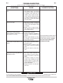
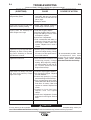
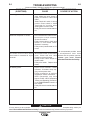
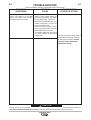
How to Use Troubleshooting Guide.......................................................................E-1
Troubleshooting Guide.............................................................................E-2 thru E-6
________________________________________________________________________
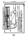
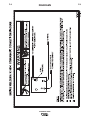
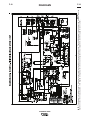
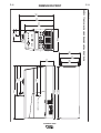
Diagrams and Dimension Print ......................................................................Section F
________________________________________________________________________
Parts List.................................................................................................................P-492
________________________________________________________________________
vii
A-1
A-1
INSTALLATION
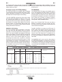
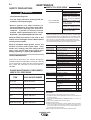
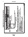
TECHNICAL SPECIFICATIONS - Ranger® 305D (K1727-3)
INPUT - DIESEL ENGINE
Make/Model
Kubota**
D722
Description
Speed (RPM)
3 cylinder
4 stroke
18.8 HP
(14 KW)
Net intermittent
3600 RPM
naturally aspirated
water cooled
Diesel Engine
Displacement
cu. in. (cu. cm.)
43.88(789)
High Idle 3650
Bore x Stroke inch (mm)
Full Load 3500
2.64 x 2.68
(67 x 68 mm)
Low Idle 2450
Starting
System
Capacities
12VDC Battery &
starter
Fuel: 12 gal.
(45 Liters)
Oil: 3.4Qts. (3.2L)
(Group 58; 550 Radiator Coolant:
cold crank amps) 3.85Qts. (3.6L)
Battery Charger
(3.6L)
RATED OUTPUT @ 104° F (40° C) - WELDER
Welding Process
DC Constant Current
DC Pipe Current
Touch-Start™TIG
DC Constant Voltage
Welding Output
Current/Voltage/Duty Cycle
305A / 29V / 100%
300A / 29V / 100%
250A / 30V / 100%
300A / 29V / 100%
Output Range
Max. Weld OCV
@Rated Load RPM
20 TO 305 AMPS
40 TO 300 AMPS
20 TO 250 AMPS
14 TO 29 VOLTS
60 Volts
RATED OUTPUT @ 104° F (40° C).- GENERATOR
Auxiliary Power 1
10,000 Watts Peak, / 9,500 Watts Continuous, 60 Hz 120/240 Volts
Sound Levels
Sound Power: 104.2 dB Lwa, Sound Level: 80.6 dBA @ 23 ft ( 7m )
PHYSICAL DIMENSIONS
HEIGHT
WIDTH
30.00* in.
21.50 in
762.0 mm
546.0 mm
DEPTH
WEIGHT
52.25 in.
698 lbs. (317kg.)
1327.0 mm
ENGINE
LUbRICATION
EMISSIONS
Full Pressure
Certified to EPA Tier 4
Compliant
with Full Flow Filter
AIR CLEANER
FUEL SYSTEM
Mechanical Fuel Pump, Auto air bleed
system Electric shutoff solenoid Indirect fuel injector
GOVERNOR
Mechanical
Governor
ENGINE IDLER
MUFFLER
ENGINE PROTECTION
Low noise Muffler:
Shutdown on low oil
Single Element
Automatic Idler
Top outlet can be rotated.
pressure & engine
Made from long life, aluminized steel.
temperature
ENGINE WARRANTY: 2 year complete (parts and labor) 3rd. year major components (parts and labor)
RECEPTACLES AND CIRCUIT bREAKERS
RECEPTACLES
AUXILIARY POWER CIRCUIT bREAKER
OTHER CIRCUIT bREAKERS
(2) 120VAC GFCI Duplex (5-20R)
(1) 120/240VAC Dual Voltage
Full KVA (14-50R)
Two 20AMP for Two Duplex Receptacle
One 50AMP for Dual Voltage(2-pole)
15AMP for Battery Charging Circuit
15AMP for 42V Wire Feeder Power
1. Output rating in watts is equivalent to volt-amperes at unity power factor. Output voltage is within ± 10% at all loads up to
rated capacity. When welding, available auxiliary power will be reduced.
* Top of enclosure add 6in. (152mm) for exhaust pipe.
** Engine warranty may vary outside of the USA. (See Engine warranty for details)
RANGER® 305D
A-2
A-2
INSTALLATION
SAFETY PRECAUTIONS
WARNING
Do not attempt to use this equipment until you
have thoroughly read the engine manufacturer’s
manual supplied with your welder. It includes
important safety precautions, detailed engine
starting, operating and maintenance instructions,
and parts lists.
-----------------------------------------------------------------------ELECTRIC SHOCK can kill.
• Do not touch electrically live parts or
electrode with skin or wet clothing.
• Insulate yourself from work and
ground
• Always wear dry insulating gloves.
-----------------------------------------------------------------------ENGINE EXHAUST can kill.
• Use in open, well ventilated areas or
vent exhaust outside.
LIFTING
The RANGER® 305D weighs approximately
775lbs.(352kg.) with a full tank of fuel (698 lbs. less
fuel). A lift bail is mounted to the machine and should
always be used when lifting the machine.
WARNING
• Lift only with equipment of adequate lifting capacity.
• be sure machine is stable when lifting.
• Do not lift this machine using lift
bail if it is equipped with a heavy
accessory such as trailer or gas
cylinder.
FALLING
EQUIPMENT can
cause injury.
• Do not lift machine if lift bail is
damaged.
• Do not operate machine while
suspended from lift bail.
-----------------------------------------------------------------------MOVING PARTS can injure.
• Do not operate with doors open or
guards off.
• Stop engine before servicing.
• Keep away from moving parts.
------------------------------------------------------------------------
See additional warning information at
front of this operator’s manual.
Only qualified personnel should install,
use, or service this equipment.
LOCATION AND VENTILATION
--------------------------------------------------------------------------------
HIGH ALTITUDE OPERATION
At higher altitudes, output derating may be necessary. For maximum rating, derate the machine 2.5% to 3.5% for every 1000 ft.
(305m). Due to new EPA and other local emissions regulations,
modifications to the engine for high altitude are restricted within
the United States and some other European Countries. Use
above 6000 ft.(1828 m) may be limited due to poor engine performance or excessive exhaust smoke. An authorized Kubota
engine field service shop should be contacted to determine if
any adjustments can be made for operation in higher elevations
locally.
The welder should be located to provide an unrestricted flow of clean, cool air to the cooling air inlets and to
avoid restricting the cooling air outlets. Also, locate the
welder so that the engine exhaust fumes are properly
vented to an outside area.
HIGH TEMPERATURE OPERATION
At temperatures above 104°F(40°C), Welder output derating is
necessary. For maximum output ratings, derate the welder output 2 volts for every 50°F(10°C) above 104°F(40°C).
STACKING
Cold weather starting:
RANGER® 305D machines cannot be stacked.
ANGLE OF OPERATION
Engines are designed to run in the level condition
which is where the optimum performance is achieved.
The maximum angle of continuous operation is 20
degrees in all directions, 35 degrees Intermittent (less
than 10 minutes continuous) in all directions. If the
engine is to be operated at an angle, provisions must
be made for checking and maintaining the oil level at
the normal (FULL) oil capacity in the crankcase.
When operating the welder at an angle, the effective
fuel capacity will be slightly less than the specified 12
gallons (45ltrs.).
With a fully charged battery and the proper weight oil,
the engine should start satisfactorily even down to
about 5°F (-15°C). If the engine must be frequently
started at or below 23°F (-5°C), it may be desirable to
install cold-starting aides. The use of No. 1D diesel
fuel is recommended in place of No. 2D at temperatures below 23°F (-5°C). Allow the engine to warm up
before applying a load or switching to high idle.
Note: Extreme cold weather starting may require
longer glow plug operation.
WARNING
Under no conditions should ether or other starting
fluids be used with this engine!
--------------------------------------------------------------------------------
RANGER® 305D
A-3
A-3
INSTALLATION
PRE-OPERATION ENGINE SERVICE
TOWING
The recommended trailer for use with this equipment for road,
in-plant and yard towing by a vehicle(1) is Lincoln’s K957-1. If
the user adapts a non-Lincoln trailer, he must assume responsibility that the method of attachment and usage does not result
in a safety hazard nor damage the welding equipment. Some of
the factors to be considered are as follows:
1. Design capacity of trailer vs. weight of Lincoln equipment and
likely additional attachments.
2. Proper support of, and attachment to, the base of the welding equipment so there will be no undue stress to the framework.
3. Proper placement of the equipment on the trailer to insure
stability side to side and front to back when being moved
and when standing by itself while being operated or serviced.
4. Typical conditions of use, i.e., travel speed; roughness of surface on which the trailer will be operated; environmental conditions; like maintenance.
5. Conformance with federal, state and local laws.(1)
(1) Consult applicable federal, state and local laws regarding specific
requirements for use on public highways.
VEHICLE MOUNTING
WARNING
READ the engine operating and maintenance instructions supplied with this machine.
WARNING
• Stop engine and allow to cool before fueling
• Do not smoke when fueling.
• Fill fuel tank at a moderate rate and do not overfill.
• Wipe up spilled fuel and allow fumes to clear
before starting engine.
• Keep sparks and flame away from tank.
--------------------------------------------------------------------------------
OIL
The RANGER® 305D is shipped with the engine
crankcase filled with high quality SAE 10W-30 Oil that
meets classification CG-4 or CH-4 for diesel engines.
Check the oil level before starting the engine. If it is
not up to the full mark on the dip stick, add oil as
required. Check the oil level every four hours of running time during the first 50 running hours. Refer to
the engine Operator’s Manual for specific oil recommendations and break-in information. The oil change
interval is dependent on the quality of the oil and the
operating environment. Refer to the Engine Operator’s
Manual for more details on the proper service and
maintenance intervals.
FUEL
Improperly mounted concentrated loads may
cause unstable vehicle handling and tires or other
components to fail.
• Only transport this Equipment on serviceable
vehicles which are rated and designed for such
loads.
• Distribute, balance and secure loads so vehicle
is stable under conditions of use.
• Do not exceed maximum rated loads for components such as suspension, axles and tires.
• Mount equipment base to metal bed or frame of
vehicle.
• Follow vehicle manufacturer’s instructions.
--------------------------------------------------------------------------------
DIESEL FUEL ONLY-Low sulphur fuel or ultra low
sulphur fuel in U.S.A. and Canada.
WARNING
• Fill the fuel tank with clean, fresh fuel. The
capacity of the tank is 12 gals. (45.4ltrs). When
the fuel gauge reads empty the tank contains
approximately 2 gals. (7.6ltrs.) of reserve fuel.
WARNING
NOTE: A fuel shut off valve is located on the prefilter/sediment filter. Which should be in
the closed position when the welder is not
ran for extended periods of time.
--------------------------------------------------------------------------------
RANGER® 305D
A-4
A-4
INSTALLATION
REMOTE CONTROL
ENGINE COOLING SYSTEM
WARNING
Air to cool the engine is drawn in the base sides
and exhaust through radiator & case back. It is
important that the intake and exhaust air is not
restricted. Allow a minimum clearance of 2 feet
(0.6m) from the case back and 16in.(406mm) from
either side of the base to a vertical surface.
The RANGER® 305D is equipped with a 6-pin and a
14-pin connector. The 6-pin connector is for connecting the K857 or K857-1 Remote Control or for TIG
welding, the K870 foot Amptrol or the K936-3 hand
Amptrol. When in the CC-STICK, DOWNHILL PIPE,
or CV-WIRE modes and when a remote control is
connected to the 6-pin Connector, the auto-sensing
circuit automatically switches the OUTPUT control
from control at the welder to remote control.
--------------------------------------------------------------------------------
When in TOUCH START TIG mode and when a
Amptrol is connected to the 6-Pin Connector, the
OUTPUT dial is used to set the maximum current
range of the CURRENT CONTROL of the Amptrol.
bATTERY CONNECTION
CAUTION
Use caution as the electrolyte is a strong acid that
can burn skin and damage eyes.
--------------------------------------------------------------------------------
The RANGER® 305D is shipped with the negative
battery cable disconnected. Make certain that the
RUN-STOP switch is in the STOP position. Remove
the two screws from the rear battery tray using a
screwdriver or a 3/8" socket. Attach the negative battery cable to the negative battery terminal and tighten
using a 1/2" socket or wrench.
NOTE: This machine is furnished with a wet charged
battery; if unused for several months, the battery may
require a booster charge. Be careful to charge the battery with the correct polarity.
The 14-pin connector is used to directly connect a
wire feeder control cable. In the CV-WIRE mode,
when the control cable is connected to the 14-pin connector, the auto-sensing circuit automatically makes
the Output Control inactive and the wire feeder voltage control active
WARNING
NOTE: When a wire feeder with a built in welding
voltage control is connected to the 14-pin connector, do not connect anything to the 6-pin connector.
--------------------------------------------------------------------------------
ELECTRICAL CONNECTIONS
MUFFLER OUTLET PIPE
Using the clamp provided secure the outlet pipe to the
outlet tube with the pipe positioned such that it will
direct the exhaust in the desired direction. Tighten
using a 9/16" socket or wrench.
SPARK ARRESTER
Some federal, state or local laws may require that
gasoline or diesel engines be equipped with exhaust
spark arresters when they are operated in certain
locations where unarrested sparks may present a fire
hazard. The standard muffler included with this welder
does not qualify as a spark arrester. When required by
local regulations, a suitable spark arrester, such as
the K1898-1 must be installed and properly maintained.
WARNING
An incorrect spark arrestor may lead to damage to
the engine or adversely affect performance.
MACHINE GROUNDING
Because this portable engine driven welder creates its
own power, it is not necessary to connect its frame to
an earth ground, unless the machine is connected to
premises wiring (home, shop, etc.)
To prevent dangerous electric shock, other equipment
to which this engine driven welder supplies power
must:
WARNING
• be grounded to the frame of the welder using a
grounded type plug.
• be double insulated.
• Do not ground the machine to a pipe that carries
explosive or combustible material.
--------------------------------------------------------------------------------
--------------------------------------------------------------------------------
RANGER® 305D
A-5
A-5
INSTALLATION
When this welder is mounted on a truck or trailer, its
frame must be electrically bonded to the metal frame
of the vehicle. Use a #8 or larger copper wire connected between the machine grounding stud and the
frame of the vehicle. When this engine driven welder
is connected to premises wiring such as that in a
home or shop, its frame must be connected to the system earth ground. See further connection instructions
in the section entitled "Standby Power Connections"
as well as the article on grounding in the latest
National Electrical Code and the local code.
CAbLE INSTALLATION
Install the welding cables to your RANGER® 305D as
follows.
In general, if the machine is to be grounded, it should
be connected with a #8 or larger copper wire to a solid
earth ground such as a metal water pipe going into the
ground for at least ten feet and having no insulated
joints, or to the metal framework of a building which
has been effectively grounded.
4. Tighten the flanged nuts securely.
The National Electrical Code lists a number of alternate means of grounding electrical equipment. A
machine grounding stud marked with the symbol
is provided on the front of the welder.
WELDING TERMINALS
The RANGER® 305D is equipped with a toggle switch
for selecting "hot" welding terminal when in the "WELD
TERMINALS ON" position or "cold" welding terminal
when in the "REMOTELY CONTROLLED" position.
1. The engine must be OFF to install welding cables.
2. Remove the flanged nuts from the output terminals
.
3. Connect the electrode holder and work cables to the
weld output terminals. The terminals are identified
on the case front.
5. Be certain that the metal piece you are welding (the
“work”) is properly connected to the work clamp and
cable.
CAUTION
6. Check and tighten the connections periodically.
• Loose connections will cause the output terminals to overheat. The terminals may eventually
melt.
• Do not cross the welding cables at the output terminal connection. Keep the cables isolated and
separate from one another.
--------------------------------------------------------------------------------
WELDING OUTPUT CAbLES
With the engine off connect the electrode and work
cables to the output studs. The welding process dictates the polarity of the electrode cable. These connections should be checked periodically and tightened
with a 3/4" wrench.
Table A.1 lists recommended cable sizes and lengths
for rated current and duty cycle. Length refers to the
distance from the welder to the work and back to the
welder. Cable diameters are increased for long cable
lengths to reduce voltage drops.
TOTAL COMbINED LENGTH OF
ELECTRODE AND WORK CAbLES
Cable Length
0-100Ft. (0-30 meters)
Cable Size for
305 Amps
100% Duty Cycle
1 / 0 AWG
100-150 Ft. (30-46 meters)
2 / 0 AWG
150-200 Ft. (46-61 meters)
3 / 0 AWG
TAbLE A.1
RANGER® 305D
A-6
A-6
INSTALLATION
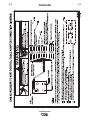
TABLE lll
ELECTRICAL DEVICE USE WITH THE RANGER® 305D
Type
Common Electrical Devices
Possible Concerns
Resistive
Heaters, toasters, incandescent
light bulbs, electric range, hot
pan, skillet, coffee maker.
NONE
Capacitive
TV sets, radios, microwaves,
appliances with electrical control.
Voltage spikes or high voltage
regulation can cause the capacitative elements to fail. Surge
protection, transient protection,
and additional loading is recommended for 100% fail-safe operation. DO NOT RUN THESE
DEVICES WITHOUT ADDITIONAL RESISTIVE TYPE
LOADS.
Inductive
Single-phase induction motors,
drills, well pumps, grinders, small
refrigerators, weed and hedge
trimmers
These devices require large
current inrush for starting.
Some synchronous motors may
be frequency sensitive to attain
maximum output torque, but
they SHOULD BE SAFE from
any frequency induced failures.
Capacitive/Inductive
Computers, high resolution TV sets,
complicated electrical equipment.
An inductive type line conditioner along with transient and
surge protection is required, and
liabilities still exist. DO NOT
USE THESE DEVICES WITH A
RANGER® 305D
The Lincoln Electric Company is not responsible for any damage to electrical components improperly connected
to the RANGER® 305D.
RANGER 305D
A-7
INSTALLATION
AUXILIARY POWER RECEPTACLES
Start the engine and set the “IDLER” control switch to
the “High Idle” mode. Voltage is now correct at the
receptacles for auxiliary power. This must be done
before a tripped GFCI receptacle can be reset properly. See the MAINTENANCE section for detailed
information on testing and resetting the GFCI receptacle.
The auxiliary power of the RANGER® 305D consists
of two 20 Amp-120 VAC (5-20R) duplex receptacles
with GFCI protection and one 50 Amp 120/240 VAC
(14-50R) receptacle. The 240 VAC receptacle can be
split for single phase 120 VAC operation.
The auxiliary power capacity is 10,000 watts Peak,
9,500 Watts Continuous of 60 Hz, single phase
power. The auxiliary power capacity rating in watts is
equivalent to volt-amperes at unity power factor. The
max permissible current of the 240 VAC output is 40
amps. The 240 VAC output can be split to provide
two separate 120 VAC outputs with a max permissible current of 40 Amps per output to two separate
120 VAC branch circuits (these circuits cannot be
paralleled). Output voltage is within ± 10% at all loads
up to rated capacity. All auxiliary power is protected
by circuit breakers.
A-7
• Install the double-pole, double-throw switch
between the power company meter and the premises disconnect. Switch rating must be the same or
greater than the customer’s premises disconnect
and service over current protection.
• Take necessary steps to assure load is limited to
the capacity of the RANGER® 305D by installing a
50 amp, 240 VAC double pole circuit breaker.
Maximum rated load for each leg of the 240 VAC
auxiliary is 40 amperes. Loading above the rated
output will reduce output voltage below the allowable - 10% of rated voltage which may damage
appliances or other motor-driven equipment and
may result in overheating of the RANGER® 305D
engine and/or alternator windings.
• Install a 50 amp, 120/240 VAC plug (NEMA Type
14-50) to the double-pole circuit breaker using No.
6, 4 conductor cable of the desired length. (The 50
amp, 120/240 VAC plug is available in the optional
K802R plug kit or as part number T12153-9.)
• Plug this cable into the 50 Amp, 120/240 Volt receptacle on the RANGER® 305D case front.
The 120 V auxiliary power receptacles should only be
used with three wire grounded type plugs or
approved double insulated tools with two wire plugs.
The current rating of any plug used with the system
must be at least equal to the current capacity of the
associated receptacle.
NOTE: The 240 V receptacle has two 120 V circuits,
but are of opposite polarities and cannot be paralleled.
STANDbY POWER CONNECTIONS
The RANGER® 305D is suitable for temporary,
standby or emergency power using the engine manufacturer’s recommended maintenance schedule.
The RANGER® 305D can be permanently installed
as a standby power unit for 240 VAC, 3 wire, single
phase, 40 amp service. Connections must be made
by a licensed electrician who can determine how the
120/240 VAC power can be adapted to the particular
installation and comply with all applicable electrical
codes.
RANGER® 305D
A-8
A-8
INSTALLATION
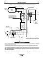
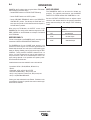
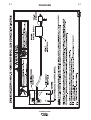
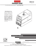
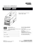
CONNECTION OF RANGER® 305D TO PREMISES WIRING
240 VOLT
GROUNDED CONDUCTOR
POWER
240 Volt
60 Hz.
3-Wire
Service
120 VOLT
COMPANY
120 VOLT
METER
NEUTRAL
BUS
N
LOAD
DOUBLE POLE DOUBLE THROW
SWITCH RATING TO BE THE SAME
AS OR GREATER THAN PREMISES
SERVICE OVERCURRENT
PROTECTION.
GROUND
50AMP
240 VOLT
50 AMP, 120/240
VOLT PLUG
NEMA TYPE 14-50
240 VOLT
PREMISES
DISCONNECT AND
SERVICE
OVERCURRENT
PROTECTION
DOUBLE
POLE
CIRCUIT
BREAKER
GND
N
50 AMP, 120/240 VOLT
RECEPTACLE
NOTE: No. 6 COPPER CONDUCTOR CABLE SEE
NATIONAL ELECTRICAL CODE FOR ALTERNATE WIRE
SIZE RECOMMENDATIONS.
WARNING
• Only a licensed, certified, trained electrician should install the machine to a premises or residential
electrical system. be certain that:
• The installation complies with the National Electrical Code and all other applicable electrical codes.
240 VOLT
GROUNDED CONDUCTOR
POWER
240 Volt
60 Hz.
3-Wire
Service
120 VOLT
COMPANY
120 VOLT
METER
NEUTRAL
BUS
N
LOAD
DOUBLE POLE DOUBLE THROW
SWITCH RATING TO BE THE SAME
AS OR GREATER THAN PREMISES
SERVICE OVERCURRENT
PROTECTION.
GROUND
50AMP
240 VOLT
50 AMP, 120/240
VOLT PLUG
NEMA TYPE 14-50
240 VOLT
PREMISES
DISCONNECT AND
SERVICE
OVERCURRENT
PROTECTION
DOUBLE
POLE
CIRCUIT
BREAKER
GND
N
50 AMP, 120/240 VOLT
RECEPTACLE
NOTE: No. 6 COPPER CONDUCTOR CABLE SEE
NATIONAL ELECTRICAL CODE FOR ALTERNATE WIRE
SIZE RECOMMENDATIONS.
• The premises is isolated and no feedback into the utility system can occur. Certain state and local
laws require the premises to be isolated before the generator is linked to the premises. Check your
state and local requirements.
• A double pole, double throw transfer switch in conjunction with the properly rated double throw
circuit breaker is connected between the generator power and the utility meter.
RANGER® 305D
A-9
INSTALLATION
CONNECTION OF LINCOLN ELECTRIC
WIRE FEEDERS
Connection of LN-7 or LN-8 to the RANGER® 305D
• Shut the welder off.
• Connect the LN-7 or LN-8 per instructions on the
appropriate connection diagram in Section F.
• Set the "WIRE FEEDER VOLTMETER" switch to
either "+" or "-" as required by the electrode being
used.
• Set the "MODE" switch to the "CV WIRE " position.
• Set the "ARC CONTROL" knob to "0" initially and
adjust to suit.
• Set the "WELD TERMINALS" switch to the
"REMOTELY CONTROLLED" position.
• Set the "IDLE" switch to the "HIGH" position.
A-9
• Across The-Arc Model:
Attach the single lead from the front of the LN-15 to
work using the spring clip at the end of the lead. This
is a control lead to supply current to the wire feeder
motor; it does not carry welding current.
Set the "WELD TERMINALS" switch to "WELD TERMINALS ON"
• Control Cable Model:
Connect Control Cable between Engine Welder and
Feeder.
Set the "WELD TERMINALS" switch to "REMOTELY
CONTROLLED".
• Set the MODE switch to the "CV-WIRE " position.
• Set the "WIRE FEEDER VOLTMETER" switch to
either "+" or "-" as required by the electrode polarity
being used.
• Set the "ARC CONTROL" knob to "0" initially and
adjust to suit.
Connection of LN-15 to the Ranger® 305D
These connections instructions apply to both the LN15 Across The-Arc and Control Cable models. The
LN-15 has an internal contactor and the electrode is
not energized until the gun trigger is closed. When the
gun trigger is closed the wire will begin to feed and the
welding process is started.
• Set the "IDLE" switch to the "AUTO" position
• Shut the welder off.
• For electrode Positive, connect the electrode cable
to the "+" terminal of the welder and work cable to
the "-" terminal of the welder. For electrode
Negative, connect the electrode cable "-" terminal of
the welder and work cable to the "+" terminal of the
welder.
RANGER® 305D
A-10
INSTALLATION
A-10
Connection of LN-742, Spool Gun (K487-25) and
Cobramatic to RANGER® 305D
WARNING
Connection of the LN-25 to the RANGER® 305D
Shut off welder before making any electrical connections.
--------------------------------------------------------------------------------
The LN-25 with or without an internal contactor may
be used with the RANGER® 305D. See the appropriate connection diagram in Section F.
• Shut the welder off.
• Connect per instructions on the appropriate connection diagram in Section F.
Connection of PRINCE XL SPOOL GUN to the
Ranger® 305D
1. Shut the welder off.
2. For electrode Positive, connect the electrode
cable from the LN-25 to the "+" terminal of the
welder and work cable to the "-" terminal of the
welder. For electrode Negative, connect the electrode cable from the LN-25 to the "-" terminal of
the welder and work cable to the "+" terminal of
the welder.
3. Attach the single lead from the front of the LN-25
to work using the spring clip at the end of the lead.
This is a control lead to supply current to the wire
feeder motor; it does not carry welding current.
4. Set the MODE switch to the "CV-WIRE " position.
5. Set the "WELD TERMINALS" switch to "WELD
TERMINALS ON"
Connection of the Prince XL Spool Gun requires the
use of the K1849-1 Adapter Module.
• Shut the Welder off.
• For electrode Positive, connect the electrode cable
to the "+" terminal of the welder and work cable to
the "-" terminal of the welder. For electrode
Negative, connect the electrode cable "-" terminal of
the welder and work cable to the "+" terminal of the
welder.
• Connect the Control Cable of the Spool Gun to the
Adapter Module and connect the Control Cable of
the Adapter Module to the Welder.
• Connect the Gas Hose.
• Set the MODE switch to the "CV-WIRE " position.
6. Set the "ARC CONTROL" knob to "0" initially and
adjust to suit.
7. Set the "IDLE" switch to the "AUTO" position.
When not welding, the RANGER® 305D engine
will be at the low idle speed. If you are using an
LN-25 with an internal contactor, the electrode is
not energized until the gun trigger is closed.
• Set the "WELD TERMINALS" switch to "WELD
TERMINALS ON".
• Set the "ARC CONTROL" knob to "0" initially and
adjust to suit.
• Set the “IDLE” switch to the “HIGH” position.
8. When the gun trigger is closed, the current sensing circuit will cause the RANGER® 305D engine
to go to the high idle speed, the wire will begin to
feed and the welding process started. When welding is stopped, the engine will revert to low idle
speed after approximately 12 seconds unless
welding is resumed.
CAUTION
If you are using an LN-25 without an internal contactor, the electrode will be energized when the
Ranger® 305D is started.
--------------------------------------------------------------------------------
RANGER® 305D
b-1
b-1
OPERATION
SAFETY PRECAUTIONS
WARNING
Do not attempt to use this equipment until you
have thoroughly read the engine manufacturer’s
manual supplied with your welder. It includes
important safety precautions, detailed engine
starting, operating and maintenance instructions,
and parts lists.
-----------------------------------------------------------------------ELECTRIC SHOCK can kill.
• Do not touch electrically live parts or
electrode with skin or wet clothing.
• Insulate yourself from work and
ground
• Always wear dry insulating gloves.
• Always operate the welder with the hinged door
closed and the side panels in place.
• Read carefully the Safety Precautions page
before operating this machine. Always follow
these and any other safety procedures included
in this manual and in the Engine Instruction
Manual.
• Add oil (if necessary) to bring the level up to the full
mark. Do not overfill. Close engine door.
• Check radiator for proper coolant level. (Fill if necessary).
• See Engine Owner’s Manual for specific oil and
coolant recommendations.
ADD FUEL
WARNING
• Stop engine while fueling.
• Do not smoke when fueling.
• Keep sparks and flame away from
tank.
• Do not leave unattended while fueling.
• Wipe up spilled fuel and allow
DIESEL FUEL
fumes to clear before starting
can cause fire.
engine.
• Do not overfill tank, fuel expansion may cause overflow.
DIESEL FUEL ONLY-Low sulphur fuel or ultra low
sulphur fuel in U.S.A. and Canada.
GENERAL DESCRIPTION
--------------------------------------------------------------------------------
The RANGER® 305D is a diesel engine powered DC
multi-process welding power source and 120 / 240
volt AC power generator. The engine drives a generator that supplies three phase power for the DC welding circuit and single phase power for the AC auxiliary
outlets. The DC welding control system uses state of
the art Chopper Technology (CT tm) for superior welding performance.
• Fill the tank approximately 4 inches (100mm) from
the top of the filler neck to allow for fuel expansion .
DO NOT FILL THE TANK TO THE POINT OF
OVERFLOW.
• Remove the fuel tank cap.
FOR AUXILIARY POWER:
Start the engine and set the IDLER control switch to
the desired operating mode. Full power is available
regardless of the welding control settings providing no
welding current is being drawn.
The auxiliary power of the RANGER® 305D consists
of two 20 Amp-120 VAC (5-20R) duplex receptacles
with GFCI protection and one 50 Amp 120/240 VAC
(14-50R) receptacle. The 240 VAC receptacle can be
split for single phase 120 VAC operation. Also refer to
the AUXILIARY POWER OPERATION section later in
this chapter.
ENGINE OPERATION
Before Starting the Engine:
• Be sure the machine is on a level surface.
• Open top & side engine doors and remove the
engine oil dipstick and wipe it with a clean cloth.
Reinsert the dipstick and check the level on the dipstick.
• Replace the fuel cap and tighten securely.
• See Engine Owner’s Manual for specific fuel recommendations.
bREAK-IN PERIOD
Any engine will use a small amount of oil during its
“break-in” period. For the diesel engine on the
RANGER® 305D, break-in is about 50 running hours.
Check the oil every four hours during break-in.
Change the oil after the first 50 hours of
operation,every 100 hours thereafter. Change the oil
filter at the second oil change.
CAUTION
During break-in, subject the RANGER® 305D to
moderate loads. Avoid long periods running at
idle. before stopping the engine, remove all loads
and allow the engine to cool several minutes.
--------------------------------------------------------------------------------
RANGER® 305D
b-2
b-2
OPERATION
16
1
15
14
2
17
13
3
12
11
4
10
9
8
7
5
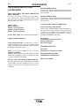
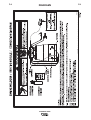
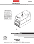
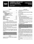
FIGURE b.1
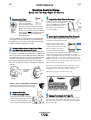
WELDING CONTROLS (Figure b.1)
1. OUTPUT CONTROL- The OUTPUT dial is
used to preset the output voltage or current as displayed on the digital meters for the four welding
modes. When in the CC-STICK, DOWNHILL PIPE
or CV-WIRE modes and when a remote control is
connected to the 6-Pin or 14-Pin Connector, the
auto-sensing circuit automatically switches the
OUTPUT CONTROL from control at the welder to
the remote control.
In the CV-WIRE mode, when the wire feeder control cable is connected to the 14-Pin Connector, the
auto-sensing circuit automatically makes OUTPUT
CONTROL inactive and the wire feeder voltage
control active.
When in the TOUCH START TIG mode and when a
Amptrol is connected to the 6-Pin Connector, the
OUTPUT dial is used to set the maximum current
range of the CURRENT CONTROL of the Amptrol.
6
2. DIGITAL OUTPUT METERS- The digital
meters allow the output voltage (CV-WIRE mode)
or current (CC-STICK,DOWN HILL PIPE and TIG
modes) to be set prior to welding using the OUTPUT control dial. During welding, the meter display the actual output voltage (VOLTS) and current (AMPS). A memory feature holds the display
of both meters on for seven seconds after welding
is stopped. This allows the operator to read the
actual current and voltage just prior to when welding was ceased.
While the display is being held the left-most decimal point in each display will be flashing. The
accuracy of the meters is +/- 3%.
3. WELD MODE SELECTOR SWITCH(Provides four selectable welding modes)
CV-WIRE
DOWNHILL PIPE
CC-STICK
TOUCH START TIG
RANGER® 305D
b-3
OPERATION
4. ARC CONTROL- The ARC CONTROL dial is active in
the CV-WIRE, CC-STICK and DOWNHILL PIPE modes,
and has different functions in these modes. This control is
not active in the TIG mode.
CC-STICK mode: In this mode, the ARC CONTROL dial
sets the short circuit current (arc-force) during stick welding
to adjust for a soft or crisp arc. Increasing the dial from –10
(soft) to +10 (crisp) increases the short circuit current and
prevents sticking of the electrode to the plate while welding.
This can also increase spatter. It is recommended that the
ARC CONTROL be set to the minimum number without
electrode sticking. Start with a setting at 0.
DOWNHILL PIPE mode: In this mode, the ARC CONTROL
dial sets the short circuit current (arc-force) during stick
welding to adjust for a soft or a more forceful digging arc
(crisp). Increasing the number from –10 (soft) to +10 (crisp)
increases the short circuit current which results in a more
forceful digging arc. Typically a forceful digging arc is preferred for root and hot passes. A softer arc is preferred for fill
and cap passes where weld puddle control and deposition
("stacking" of iron) are key to fast travel speeds. It is recommended that the ARC CONTROL be set initially at 0.
CV-WIRE mode: In this mode, turning the ARC CONTROL
clock wise from –10 (soft) to +10 (crisp) changes the arc
from soft and washed-in to crisp and narrow. It acts as an
inductance/pinch control. The proper setting depends on the
procedure and operator preference. Start with a setting of 0.
5. WELD OUTPUT TERMINALS WITH FLANGE
NUT- Provides a connection point for the electrode and
work cables.
6. GROUND STUD-
Provides a connection point for
connecting the machine case to earth ground.
7. 14-PIN CONNECTOR- For attaching wire feeder control cables to the RANGER® 305D. Includes contactor closure circuit, auto-sensing remote control circuit, and 120V
and 42V power. The remote control circuit operates the
same as the 6 Pin Amphenol.
8. 6-PIN CONNECTOR- For attaching optional remote
control equipment. Includes auto-sensing remote control
circuit.
b-3
10. WIRE FEEDER VOLTMETER SWITCH:
Matches the polarity of the wire feeder voltmeter to
the polarity of the electrode.
ENGINE CONTROLS: (Figure b.2)
11. RUN/STOP SWITCH - RUN position energizes
the engine prior to starting. STOP position stops the
engine. The oil pressure interlock switch prevents
battery drain if the switch is left in the RUN position
and the engine is not operating.
12. GLOW PLUG PUSH bUTTON • When pushed activates the glow plugs. Glow plug
should not be activated for more than 20 seconds
continuously.
13. START PUSH bUTTON Energizes the starter motor to crank the
engine.
14. IDLER SWITCH- Has two positions as follows:
1) In the HIGH position, the engine runs at the high
idle speed controlled by the engine governor.
2) In the AUTO position, the idler operates as follows:
• When switched from HIGH to AUTO or after starting
the engine, the engine will operate at full speed for
approximately 12 seconds and then go to low idle
speed.
• When the electrode touches the work or power is
drawn for lights or tools (approximately 100 Watts
minimum), the engine accelerates and operates at
full speed.
• When welding ceases or the AC power load is
turned off, a fixed time delay of approximately 12
seconds starts. If the welding or AC power load is
not restarted before the end of the time delay, the
idler reduces the engine speed to low idle speed.
• The engine will automatically return to high idle
speed when there is welding load or AC power load
reapplied.
9. WELD TERMINALS CONTROL SWITCH- In the
WELD TERMINALS ON position, the output is electrically
hot all the time. In the REMOTELY CONTROLLED position, the output is controlled by a wire feeder or amptrol
device, and is electrically off until a remote switch is
depressed.
RANGER® 305D
b-4
b-4
OPERATION
15. ELECTRIC FUEL GAUGE- The electric fuel
gauge gives accurate and reliable indication as to
how much fuel is in the fuel tank.
16. ENGINE HOUR METER- Displays the total
time that the engine has been running. This meter
is useful for scheduling prescribed maintenance.
17. ENGINE PROTECTION LIGHT- A warning
indicator light for Low Oil Pressure and/or Coolant
Over Temperature. The light is off when the systems are functioning properly. The light turns on
when the RUN-STOP switch is in the “ON” position prior to starting the engine. If the Engine
Protection or Battery Charging Lights do “not”
turn off shortly after starting the engine shut off
the engine immediately and determine the cause.
STARTING THE ENGINE
NOTE: If the unit fails to start repeat step 4 through
step 7 after waiting 30 seconds
CAUTION
• Do not allow the starter motor to run continuously
for more than 20 seconds.
• Do not push the START button while the engine
is running because this can damage the ring
gear and/or the starter motor.
• IF the Engine Protection or battery Charging
Lights do “not” turn off shortly after starting the
engine shut off the engine immediately and deter
mine the cause.
--------------------------------------------------------------------------------
NOTE: When starting a RANGER® 305D for the first
time, or after and extended period of time of not operating, it will take longer than normal because the fuel
pump has to fill the fuel system.
STOPPING THE ENGINE
1. Remove all plugs connected to the AC power
receptacles.
Remove all welding and auxiliary power loads and
2. Set IDLER switch to AUTO.
allow the engine to run at low idle speed for a few
3. Set the RUN/STOP switch to RUN.
minutes to cool the engine.
4. Press Glow Plug Button and hold 5 to 10 seconds.
5. Press and hold both the “Glow Plug” Button and
STOP the engine by placing the RUN-STOP switch in
START button together until the engine starts or for
the STOP position.
up to 10 seconds.
6. Release the engine START button immediately
NOTE: A fuel shut off valve is located on the fuel prefilter.
when the engine starts.
7. Release the glow plug button after the Engine
WELDER OPERATION
Protection Light turns off or after an additional 5
seconds maximum.
DUTY CYCLE
8. The engine will run at high idle speed for approxiDuty Cycle is the percentage of time the load is being
mately 12 seconds and then drop to low idle speed.
applied in a 10 minute period. For example a 60% duty
Allow the engine to warm up at low idle for several
cycle, represents 6 minutes of load and 4 minutes of no
minutes before applying a load and/or switching to
load in a 10 minute period.
high idle. Allow a longer warm up time in cold
weather.
TAbLE b.1
TYPICAL RANGER® 305D FUEL CONSUMPTION
Kubota D722
Gal./Hr (Liters/Hr)
Low Idle - No Load
2450 R.P.M.
High Idle - No Load
3650 R.P.M.
DC Weld Output
250 Amps @ 28 Volts
DC Weld Output
300 Amps @ 29 Volts
Running time for
12 gallons-hours
.29 (1.09)
41.77
.54 (2.06)
22.02
1.03 (3.91)
11.62
1.18 (4.47)
10.16
9,500 Watts
1.16 (4.38)
10.37
7,000 Watts
.96 (3.63)
12.50
3,000 Watts
.70 (2.67)
17.03
RANGER® 305D
b-5
b-5
OPERATION
The Ranger® 305D can be used with a broad range of DC
stick electrodes. The MODE switch provides two stick
welding settings as follows:
It is recommended that the ARC CONTROL be set to the
minimum number without electrode sticking. Start with
the dial set at 0.
Constant Current (CC-STICK) Welding
TIG WELDING
The CC-STICK position of the MODE switch is designed
for horizontal and vertical-up welding with all types of electrodes, especially low hydrogen. The output CONTROL
dial adjusts the full output range for stick welding.
The TOUCH START TIG setting of the MODE switch is
for DC TIG (Tungsten Inert Gas) welding. To initiate a
weld, the CONTROL dial is first set to the desired current
and the tungsten is touched to the work. During the time
the tungsten is touching the work there is very little voltage or current and, in general, no tungsten contamination. Then, the tungsten is gently lifted off the work in a
rocking motion, which establishes the arc.
The ARC CONTROL dial sets the short circuit current
(arc-force) during stick welding to adjust for a soft or crisp
arc. Increasing the number from -10(soft) to +10(crisp)
increases the short circuit current and prevents sticking of
the electrode to the plate while welding. This can also
increase spatter. It is recommended that the ARC CONTROL be set to the minimum number without electrode
sticking. Start with the dial set at 0.
DOWNHILL PIPE Welding
This slope controlled setting is intended for "out-of-position" and "down hill" pipe welding where the operator
would like to control the current level by changing the arc
length. The output CONTROL dial adjusts the full output
range for pipe welding. The ARC CONTROL dial sets the
short circuit current (arc-force) during stick welding to
adjust for a soft or more forceful digging arc (crisp).
Increasing the number from -10(soft) to +10(crisp)
increases the short circuit current which results in a more
forceful digging arc.Typically a forceful digging arc is preferred for root and hot passes. A softer arc is preferred for
fill and cap passes where weld puddle control and deposition (“stacking” of iron) are key to fast travel speeds. This
can also increase spatter.
TAbLE b.2
When in the TOUCH START TIG mode and when a
Amptrol is connected to the 6-Pin connector the OUTPUT dial is used to set the maximum current range of the
current control of the Amptrol.
The ARC CONTROL is not active in the TIG mode. To
STOP a weld, simply pull the TIG torch away from the
work. When the arc voltage reaches approximately 30
Volts the arc will go out and the machine will reset the
current to the Touch Start level. To reinitiate the arc,
retouch the tungsten to the work and lift. Alternatively,
the weld can be stopped by releasing the Amptrol or arc
start switch.
The RANGER® 305 D can be used in a wide variety of
DC TIG welding applications. In general the ‘Touch Start’
feature allows contamination free starting without the use
of a Hi-frequency unit. If desired, the K930-2 TIG Module
can be used with the RANGER® 305 D. The settings are
for reference.
TYPICAL CURRENT RANGES (1) FOR TUNGSTEN ELECTRODES(2)
Tungsten Electrode
Diameter in. (mm)
DCEN (-)
1%, 2% Thoriated
Tungsten
.010
0.020
0.040
(.25)
(.50)
(1.0)
2-15
5-20
15-80
DCEP (+)
Approximate Argon Gas Flow
Flow Rate C.F.H. ( l /min.)
1%, 2% Thoriated
Tungsten
Aluminum
(3)
(3)
(3)
3-8
5-10
5-10
TIG TORCH
Nozzle Size (4), (5)
Stainless Steel
(2-4)
(3-5)
(3-5)
3-8
5-10
5-10
(2-4)
(3-5)
(3-5)
#4, #5, #6
1/16
(1.6)
70-150
10-20
5-10
(3-5)
9-13
(4-6)
#5, #6
3/32
1/8
(2.4)
(3.2)
150-250
250-400
15-30
25-40
13-17
15-23
(6-8)
(7-11)
11-15
11-15
(5-7)
(5-7)
#6, #7, #8
5/32
3/16
1/4
(4.0)
(4.8)
(6.4)
400-500
500-750
750-1000
40-55
55-80
80-125
21-25
23-27
28-32
(10-12)
(11-13)
(13-15)
13-17
18-22
23-27
(6-8)
(8-10)
(11-13)
#8, #10
(1) When used with argon gas. The current ranges shown must be reduced when using argon/helium or pure helium shielding gases.
(2) Tungsten electrodes are classified as follows by the American Welding Society (AWS):
Pure
EWP
1% Thoriated
EWTh-1
2% Thoriated
EWTh-2
Though not yet recognized by the AWS, Ceriated Tungsten is now widely accepted as a substitute for 2% Thoriated Tungsten in AC and DC applications.
(3) DCEP is not commonly used in these sizes.
(4) TIG torch nozzle "sizes" are in multiples of 1/16ths of an inch:
# 4 = 1/4 in.
(6 mm)
# 5 = 5/16 in.
(8 mm)
# 6 = 3/8 in.
(10 mm)
# 7 = 7/16 in.
(11 mm)
# 8 = _ in.
(12.5 mm)
#10 = 5/8 in.
(16 mm)
(5) TIG torch nozzles are typically made from alumina ceramic. Special applications may require lava nozzles, which are less prone to breakage, but cannot withstand high temperatures
and high duty cycles.
RANGER® 305D
b-6
b-6
OPERATION
RANGER® 305 D settings when using the K930-2 TIG Module
with an Amptrol or Arc Start Switch:
• Set the MODE Switch to the TOUCH START TIG setting.
• Set the "IDLER" Switch to the "AUTO" position.
• Set the "WELDING TERMINALS" switch to the "REMOTELY
CONTROLLED" position. This will keep the "Solid State" contactor open and provide a "cold" electrode until the Amptrol or
Arc Start Switch is pressed.
When using the TIG Module, the OUTPUT control on the
RANGER® 305 D is used to set the maximum range of the CURRENT CONTROL on the TIG Module or an Amptrol if connected
to the TIG Module.
WIRE WELDING-CV
Connect a wire feeder to the RANGER® 305 D according to the
instructions in INSTALLATION INSTRUCTIONS Section.
ARC GOUGING
The RANGER® 305D can be used for limited arc
gouging. For optimal performance, set the MODE
switch to CC-STICK and the ARC CONTROL to +10.
Set the OUTPUT CONTROL knob to adjust output
current to the desired level for the gouging electrode
being used according to the ratings in the following
Table.
Carbon Diameter
Current Range (DC, electrode
positive)
1/8"
60-90 Amps
5/32"
90-150 Amps
3/16"
200-250 Amps
The RANGER® 305 D in the CV-WIRE mode, permits it to be
used with a broad range of flux cored wire (Innershield and
Outershield) electrodes and solid wires for MIG welding (gas
metal arc welding). Welding can be finely tuned using the ARC
CONTROL. Turning the ARC CONTROL clockwise from –10
(soft) to +10 (crisp) changes the arc from soft and washed-in to
crisp and narrow. It acts as an inductance/pinch control. The
proper setting depends on the procedure and operator preference. Start with the dial set at 0.
Listed below are some wires suitable for use on this machine:
• Innershield - NR-311, NS-3M, NR-207, NR-203 Ni 1%,
NR-212.
• Outershield - 0S-70, 0S-71M, 0S-71 ELITE.
• Solid wires for MIG welding - .035 (0.9 mm), and
.045 (1.1 mm), Super Arc L-50 and L-56, .035 (0.9 mm) and
.045 (1.1 mm) Blue Max MIG 308 LS.
Contact your local authorized Lincoln Electric Distributor or the
Lincoln Electric Company for specific wires used on certain applications with this machine.
RANGER® 305D
b-7
b-7
OPERATION
AUXILIARY POWER:
If a GFCI receptacle is tripped, See the MAINTENANCE section for detailed information on testing and
resetting the GFCI receptacle.
Start the engine and set the IDLER control switch to
the desired operating mode. Full power is available
regardless of the welding control settings providing no
welding current is being drawn.
The auxiliary power of the RANGER® 305D consists
of two 20 Amp-120 VAC GFCI (5-20R) duplex receptacles and one 50 Amp 120/240 VAC (14-50R) receptacle. The 240 VAC receptacle can be split for single
phase 120 VAC operation. The auxiliary power capacity is 10,000 watts Peak, 9500 Watts continuous of 60
Hz, single phase power. The auxiliary power capacity
rating in watts is equivalent to volt-amperes at unity
power factor. The max permissible current of the 240
VAC output is 44 Amps. The 240 VAC output can be
split to provide two separate 120 VAC outputs with a
max permissible current of 44 Amps per output to two
separate 120 VAC branch circuits (these circuits cannot be paralleled). Output voltage is within ± 10% at
all loads up to rated capacity. All auxiliary power is
protected by circuit breakers.
The 120 V auxiliary power receptacles should only be
used with three wire grounded type plugs or approved
double insulated tools with two wire plugs. The current
rating of any plug used with the system must be at
least equal to the current capacity of the associated
receptacle.
NOTE: The 240 V receptacle has two circuits, each of
which measure 120 V to neutral but are of opposite
polarities and cannot be paralleled.
Simultaneous Welding and Auxiliary Power Loads
The above auxiliary power ratings are with no welding
load. Simultaneous welding and power loads are
specified in the following table. The permissible currents shown assume that current is being drawn from
either the 120 VAC or 240 VAC supply (not both at the
same time).
RANGER® 305D Simultaneous Welding and Power Loads
Welding
Output-Amps
Permissible Power-Watts
(Unity Power Factor)
Permissible Auxiliary
Current in -Amps
@ 240 VAC
9000
0
44
7500
100
31
5800
150
24
4500
200
19
2800
250
12
700
300
3
* Each duplex receptacle is limited to 20 amps.
** Not to exceed 44A per 120 VAC branch circuit when splitting the 240 VAC output.
RANGER® 305D Extension Cord Length Recommendations
(Use the shortest length extension cord possible sized per the following table.)
Current Voltage Load
(Amps) Volts (Watts)
15
120
1800
20
120
2400
15
240
3600
20
240
4800
44
240
9500
Maximum Allowable Cord Length in ft. (m) for Conductor Size
12 AWG
10 AWG
8 AWG
6 AWG
40
(12)
75
(23)
125
(38)
175
(53)
30
(9)
50
(15)
88
(27)
138
(42)
(18)
75
(23)
150
(46)
225
(69)
350
(107)
60
(18)
100
(30)
175
(53)
275
(84)
50
(15)
90
(27)
150
(46)
Conductor size is based on maximum 2.0% voltage drop.
14 AWG
30
(9)
60
RANGER® 305D
4 AWG
300
(91)
225
(69)
600
(183)
450
(137)
225
(69)
C-1
ACCESSORIES
FIELD INSTALLED OPTIONS /
ACCESSORIES
K957-1 HEAVY DUTY, TWO WHEEL TRAILER FOR
SMALL WELDERS
For road, off-road and in-plant and yard towing.
(For highway use, consult applicable federal, state
and local laws regarding requirements for brakes,
lights, fenders, etc.).Order:
K957-1
K958-1
K958-2
K959-2
K965-1
C-1
K802-N POWER PLUG KIT
Provides four 120 volt plugs rated at 20 amps each
and one dual voltage, full KVA plug rated at 120/240
volts, 50 amps.
K802-R POWER PLUG KIT
Provides four 120 volt plugs rated at 15 amps each
and one dual voltage, full KVA plug rated at 120/240
volts, 50 amps.
T12153-9 50 AMP, 120/240 V POWER PLUG
Trailer
ball Hitch
Lunette Eye Hitch
Fender & Light Kit
Cable Storage Rack
K1789-1 ROLL CAGE - Gives added damage protection.
K1898-1 SPARK ARRESTOR
K704 ACCESSORY SET - Includes 35 ft. (10m) of
electrode cable and 30 ft. (9.1m) of work cable, headshield, work clamp electrode holder. Cables are rated
at 400 amps, 100% duty cycle.
K857 25 ft (7.6m) or K857-1 100 ft. (30.4m)
REMOTE CONTROL
Portable control provides same dial range as the output control on the welder. Has a convenient 6 pin plug
for easy connection to the welder.
K1816-1 FULL KVA ADAPTER KIT
Plugs into the 120/240V NEMA 14-50R receptacle on
the case front (which accepts 4-prong plugs) and
converts it to a NEMA 6-50R receptacle, (which
accepts 3-prong plugs.) For connection of Lincoln
equipment with NEMA 6-50R plug.
TIG Welding
K1783-9 TIG Torch PTA-26V (25ft.)
K963-3 Hand Amptrol
K870 Foot Amptrol
KP509 Magnum Parts Kit
Spool Gun
K1692-2 Prince XL Spool Gun (25ft.)
K487-25 Magnum Spool Gun
K488 Magnum Control Module
K691-10 Input Cable)
K2174-1 COLD WEATHER OPERATIONS KITProvides starting aid and enhancement in extreme
cold weather. Includes radiator grill cover, oil pan
heater, coolant Lester and all hardware required for
installation.
RANGER® 305D
D-1
D-1
MAINTENANCE
KUbOTA D722 DIESEL ENGINE
SAFETY PRECAUTIONS
FREQUENCY
WARNING
• Have qualified personnel do all maintenance
and troubleshooting work.
• Turn the engine off before working inside the
machine or servicing the engine.
• Remove guards only when necessary to
perform maintenance and replace them when
the maintenance requiring their removal is
complete. If guards are missing from the
machine, obtain replacements from a Lincoln
Distributor. (See Operating Manual Parts List.)
Read the Safety Precautions in the front of this
manual and in the Engine Owner’s Manual before
working on this machine.
Keep all equipment safety guards, covers, and
devices in position and in good repair. Keep
hands, hair, clothing, and tools away from the
gears, fans, and all other moving parts when
starting, operating, or repairing the equipment.
DAILY OR BEFORE
STARTING ENGINE
Service Intervals
Observe the following for service and maintenance. The lubricating
oil change intervals listed in the table below are for Classes CF,CE
and CD lubricating oils of API classification with a low sulfur fuel in
use. If the CF-4 or CG-4 lubricating oil is used with a high-sulfur
fuel, change the lubricating oil at shorter intervals than recommended in the table below depending on the operating condition.
Intervals
ENGINE MAINTENANCE COMPONENTS
KUbOTA D722 DIESEL ENGINE
ITEM
OIL FILTER
MAKE AND PART NUMbER
KUBOTA 70000-15241
AIR FILTER ELEMENT DONALDSON P822686
FUEL FILTER ELEMENT KUBOTA 15231-43560
BATTERY
KUBOTA GROUP 58, 550 CCA
BELT
KUBOTA 15881-97011
GLOW PLUGS
KUBOTA 16851-65512
INLINE FUEL FILTER
KUBOTA 12581-43012
Items
Every 50 hours
Every 75 hours
Check of fuel pipes and clamp bands.
Change of engine oil
Every 100 hours
Inspect/Clean air cleaner element *1
and Vacuator™ valve.
Cleaning of fuel filter.
Check the battery electrolyte level.
Check the fan belt tightness.
Check the radiator and hose clamps. •
Replacement of oil filter cartridge
Check the intake air lines.
*1,*2
Replacement of Air Filter element.
Replacement of fuel filter element.
Cleaning of water jacket (radiator
interior).
Replacement of fan belt.
Routine Maintenance
At the end of each day’s use, refill the fuel tank to
minimize moisture condensation in the tank. Running
out of fuel tends to draw dirt into the fuel system.
Also, check the crankcase oil level and add oil if
indicated.
MAINTENANCE REQUIRED
• FILL FUEL TANK.
• CHECK OIL LEVEL.
• CHECK COOLANT LEVEL.
• CHECK AIR CLEANER ELEMENT AND HOUSING FOR
DIRTY, LOOSE OR DAMAGED
PARTS.
• CHECK AIR INTAKE HOSE
FOR CRACKS OR LOOSE
CONNECTIONS.
• CHECK AIR INTAKE/EXHAUST
AREAS & RADIATOR FOR
DIRT. CLEAN AS NECESSARY.
• CHECK ALTERNATOR BELT
TENSION AND WEAR.
Every 150 hours
Every 200 hours
Every 400 hours
Every 500 hours
Every 1 or 2 months Recharging of Battery.
Check of valve clearance.
Every 800 hours
Check the fuel injection nozzle injecEvery 1500 hours
tion pressure.
Every 3000 hours Check of injection pump.
Check of fuel injector timer.
Replacement of battery
Every 2 years
Replacement of radiator hoses and
clamp band.
Replacement of fuel pipes and
clamps.
Change the radiator coolant.(L.L.C.)
Replacement of intake air line.
@
•
@
@
@
@
*3
*3
@
@
*3
*3
@
@
*4
@
IMPORTANT
• These jobs should be done after the first 50 hours of operation.
*1 Air cleaner should be inspected/cleaned more often in dusty conditions than
the normal conditions.
*2 Follow Service Instructions and Installation Tips for air cleaner in
Section D.
*3 Consult your local KUBOTA Dealer for this service.
*4 Replace only if necessary.
@ All these markings are registered as emission related critical parts by KUBOTA in the U.S. EPA nonroad emission regulation. As the engine owner,
you are responsible for the performance of the required maintenance on
the according to the above instruction.
Please see Engine Owners Manual for Warranty Statement in detail.
RANGER® 305D
D-2
D-2
MAINTENANCE
Engine Oil Change
Drain the engine oil while the engine is warm to
assure rapid and complete draining. It is recommended that each time the oil is changed the oil filter be
changed as well.
• Be sure the unit is off. Disconnect the negative battery cable to ensure safety.
• Locate oil drain hose and valve in bottom of base
and pull through the hole in the battery access panel
on the welder.
• Remove the cap from the drain valve. Push valve in
and twist counterclockwise. Pull to open and drain
the oil into a suitable container for disposal.
• Close the drain valve by pushing in and twisting
clockwise. Replace the cap.
• Re-fill the crankcase to the upper limit mark on the
dipstick with the recommended oil (see engine operation manual OR engine service items decal OR
below). Replace and tighten the oil filler cap securely.
• Push oil drain hose and valve back into unit, re-connect negative battery cable, and close doors and
engine top cover before restarting unit.Wash your
hands with soap and water after handling used
motor oil. Please dispose of used motor oil in a
manner that is compatible with the environment.
We suggest you take it in a sealed container to your
local service station or recycling center for reclamation. DO NOT throw it in the trash; pour it on the
ground or down a drain.
Engine Oil Refill capacities
Without oil filter replacement:
• 3.3 U.S. Quart. (2.7 Imp Quart, 3.2 liter)
Oil Filter Change
• Drain the oil.
• Remove the oil filter with an oil filter wrench and
drain the oil into a suitable container. Discard the
used filter. Note: Care should be taken during filter
removal to not disrupt or damage in any way the fuel
lines.
• Clean the filter mounting base and coat the gasket
of the new filter with clean engine oil.
• Screw the new filter on by hand until the gasket contacts the mounting base. Using an oil filter wrench,
tighten the filter an additional 1/2 to 7/8 of a turn.
• Refill the crankcase with the specified amount of the
recommended engine oil. Reinstall the oil filler cap
and tighten securely.
• Start the engine and check for oil filter leaks.
• Stop the engine and check the oil level. If necessary, add oil to the upper limit mark on the dipstick.
WARNING
• Never use gasoline or low flash point solvents
for cleaning the air cleaner element. A fire or
explosion could result.
CAUTION
• Never run the engine without the air cleaner.
Rapid engine wear will result from contaminants,
such as dust and dirt being drawn into the
engine.
--------------------------------------------------------------------------------
AIR CLEANER
With oil filter replacement:
• 3.4 U.S. Quart. (3.0 Imp Quart, 3.2 liter)
The diesel engine is equipped with a dry type air filter.
Never apply oil to it. Service the air cleaner as follows:
Use motor oil designed for diesel engines that meets
requirements for API service classification
CC/CD/CE/CF/CF-4/CG-4 or CH-4.
ACEA E1/E2/E3. Always check the API service label
on the oil container to be sure it includes the letters
indicated. (Note: An S-grade oil must not be used in a
diesel engine or damage may result. It IS permissible
to use an oil that meets S and C grade service classifications.)
SAE 10W30 is recommended for general, all temperature use, 5F to 104F (-15C to 40C).
See engine owner’s manual for more specific information on oil viscosity recommendations.
Replace the element at least every 200 hours of
operation and sooner under dusty conditions.
RANGER® 305D
D-3
D-3
MAINTENANCE
Service Instructions
Single- and Two-Stage Engine Air Cleaners
Inspect the New Filter for Damage
Remove the Filter
Rotate the
filter while
pulling
straight out.
Unfasten or unlatch the
service cover. Because
the filter fits tightly over the
outlet tube to create the critical seal, there will
be some initial resistance, similar to breaking
the seal on a jar. Gently move the end of the filter
back and forth to break the seal then rotate while
pulling straight out. Avoid knocking the filter
against the housing.
If your air cleaner has a safety filter, replace it every third primary
filter change. Remove the safety filter as you would the primary
filter. Make sure you cover the air cleaner outlet tube to avoid any
unfiltered contaminant dropping into the engine.
Clean Both Surfaces of the Outlet Tube
and Check the Vacuator™ Valve
Use a clean cloth to wipe the filter sealing surface and the inside of
the outlet tube. Contaminant on the sealing surface could hinder an
effective seal and cause leakage. Make sure that all contaminant is
removed before the new filter is inserted. Dirt accidently transferred
to the inside of the outlet tube will reach the engine and cause
wear. Engine manufacturers say that it takes only a few grams of
dirt to "dust" an engine! Be careful not to damage the sealing area
on the tube.
Wipe both sides
of the outlet
tube clean.
Outer edge of the
outlet tube
Inspect the new filter carefully, paying attention to
the inside of the open end, which is the
sealing area. NEVER install a damaged
filter. A new Donaldson radial seal
filter may have a dry lubricant on the
seal to aid installation.
Insert the New Radial Seal Filter Properly
If you're servicing the safety filter, this should be seated into
position before installing the primary filter.
Insert the new filter carefully. Seat
the filter by hand, making certain it is
completely into the air cleaner housing
before securing the cover in place.
The critical sealing area will stretch
slightly, adjust itself and distribute the sealing pressure evenly. To
complete a tight seal, apply pressure by hand at the outer rim of
the filter, not the flexible center. (Avoid pushing on the center of the
urethane end cap.) No cover pressure is required to hold the seal.
NEVER use the service cover to push the filter into place! Using the
cover to push the filter in could cause damage to the housing, cover
fasteners and will void the warranty.
If the service cover hits the filter before it is fully in place, remove
the cover and push the filter (by hand) further into the air cleaner
and try again. The cover should go on with no extra force.
Once the filter is in place, secure the service cover.
Inner edge of the
outlet tube
If your air cleaner is equipped with a Vacuator Valve
Visually check and physically squeeze to make sure the
valve is flexible and not inverted, damaged or plugged.
Caution
NEVER use the service cover to
push the filter into place! Using
the cover to push the filter in could
cause damage to the housing, cover
fasteners and will void the warranty.
Inspect the Old
Filter for Leak Clues
Visually inspect the old filter for any signs
of leaks. A streak of dust on the clean side
of the filter is a telltale sign. Remove any
cause of leaks before installing new filter.
Check Connectors for Tight Fit
Make sure that all mounting bands, clamps, bolts, and connections
in the entire air cleaner system are tight. Check for holes in piping
and repair if needed. Any leaks in your intake piping will send dust
directly to the engine!
RANGER® 305D
D-4
D-4
MAINTENANCE
FUEL
COOLING SYSTEM
WARNING
HOT COOLANT can burn skin.
• Do not remove cap if radiator is
hot.
-----------------------------------------------------------------------Check the coolant level by observing the level in the
radiator and recovery bottle. Add 50/50 antifreeze /
water solution if the level is close to or below the
"LOW" mark. do not fill above the "FULL" mark.
Remove radiator cap and add coolant to radiator. Fill
up to the top of the tube in the radiator filler neck
which includes a connecting hose coming from the
thermostat housing.
To drain the coolant, open the petcock at the bottom
of the radiator. Open the radiator cap to allow complete drainage. (Tighten the petcock and refill with a
50/50 antifreeze/water solution.) Use an automotive
grade (low silicate) ethylene glycol antifreeze. The
cooling system capacity is 3.85 quarts (3.6L.).
Squeeze upper and lower radiator hoses while filling
to bleed air from system coolant. Replace and tighten
the radiator cap.
At the end of each day’s use, refill the fuel tank to minimize moisture condensation and dirt contamination in
the fuel line. Do not overfill; leave room for the fuel to
expand.
Use only fresh, No. 2 grade DIESEL fuel. Do not use
kerosene.
See the Engine Operator's Manual for instructions on
replacing the fuel filter.
bLEEDING THE FUEL SYSTEM
You may need to bleed air from the fuel system if the
fuel filter or fuel lines have been detached, the fuel
tank has been ran empty or after periods of long storage. It is recommended that the fuel shutoff valve be
closed during periods of non-use.
The Kubota D722 engine supplied with this welder is
equipped with an automatic bleeding mechanism that
helps purge the air from the mechanical fuel pump
system. It is generally not necessary to open a vent
screw or fuel line fitting to bleed the fuel system.
Operate the priming lever on the pump to assist starting after extended periods of non-use or out of fuel
conditions.
CAUTION
WARNING
Always premix the antifreeze and clean tap water
before adding to the radiator. It is very important
that a precise 50/50 solution be used with this
engine year round. This gives proper cooling during hot weather and freezing protection to -34° F (37° C).
Coo