1
Cisco IP Telephony Troubleshooting Guide for Cisco CallManager Release 3.0(1)
Cisco IP Telephony Troubleshooting Guide
for Cisco CallManager Release 3.0(1)
Contents
Purpose ............................................................................................................................................ 4
Version ............................................................................................................................................ 4
Topology ......................................................................................................................................... 4
Documentation Checklist ............................................................................................................ 5
Glossary of Terms ........................................................................................................................... 6
Tools and Utilities to Monitor and Troubleshoot Cisco CallManager.......................................... 10
Cisco CallManager Administration Details .............................................................................. 10
Microsoft Performance.............................................................................................................. 11
Opening Microsoft Performance........................................................................................... 11
Customizing Performance ..................................................................................................... 11
Microsoft Event Viewer ............................................................................................................ 12
Opening Event Viewer .......................................................................................................... 12
Detailed Information about Events ....................................................................................... 13
SDI Trace .................................................................................................................................. 13
SDI Trace Output .................................................................................................................. 13
Configuring Traces................................................................................................................ 14
SDL Trace ................................................................................................................................. 15
Enabling SDL Trace.............................................................................................................. 15
Disk Space Warning.............................................................................................................. 17
Sniffer Trace.............................................................................................................................. 18
Sniffer Trace Applications .................................................................................................... 18
Call Detail Records (CDR) and Call Management Records (CMR) ........................................ 18
Enabling or Disabling CDRs................................................................................................. 19
CDRs ..................................................................................................................................... 20
Diagnostic CDRs (Also Known As CMRs).......................................................................... 20
Problem Categories ....................................................................................................................... 21
Voice Quality ............................................................................................................................ 21
Lost or Distorted Audio......................................................................................................... 21
i Button Help ......................................................................................................................... 24
Crackling ............................................................................................................................... 25
Check Your Loads................................................................................................................. 25
Echo....................................................................................................................................... 25
Check Your Loads............................................................................................................. 26
One-Way Audio or No Audio ............................................................................................... 26
MTP and One-Way Audio .................................................................................................... 27
Phone Resets ............................................................................................................................. 27
Dropped Calls............................................................................................................................ 28
Check Your Loads................................................................................................................. 31
Cisco CallManager Feature Issues ............................................................................................ 31
Codec/Regions: Codec Mismatch ......................................................................................... 31
Locations ............................................................................................................................... 32
© 2000 Cisco Systems, Inc.
1
Cisco IP Telephony Troubleshooting Guide for Cisco CallManager Release 3.0(1)
Conference Bridge................................................................................................................. 32
Transcoding Problems........................................................................................................... 33
MTP Resource Problems....................................................................................................... 35
Dial Plans .............................................................................................................................. 37
Partitions................................................................................................................................ 38
Security.................................................................................................................................. 40
Slow Server Response............................................................................................................... 42
Reorder Tone Through Gateways ............................................................................................. 42
Gateway Registration Problems ................................................................................................ 43
Gatekeeper Problems................................................................................................................. 48
Inter-Cluster Trunks Only ..................................................................................................... 48
Admission Rejects (ARJ)...................................................................................................... 48
Registration Rejects (RRJ).................................................................................................... 49
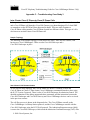
Intra-Cluster Cisco IP Phone-to-Cisco IP Phone Calls ................................................................. 50
Sample Topology ...................................................................................................................... 50
Cisco IP Phone Initialization Process........................................................................................ 50
Skinny Station Registration Process ......................................................................................... 52
Cisco IP Phone-to-Cisco IP Phone Call Flow within a Cluster ................................................ 53
Cisco IP Phone-to-Cisco IP Phone Exchange of Skinny Station Messages during Call Flow . 54
Cisco CallManager Initialization Process ................................................................................. 55
Self-Starting Processes.............................................................................................................. 56
Cisco CallManager Registration Process .................................................................................. 57
Cisco CallManager KeepAlive Process .................................................................................... 58
Cisco CallManager Intra-Cluster Call Flow Traces.................................................................. 59
Cisco IP Phone-to-Cisco IOS Gateway Calls ............................................................................... 63
Sample Topology ...................................................................................................................... 63
Call Flow Traces ....................................................................................................................... 63
Debug Messages and Show Commands on the Cisco IOS Gatekeeper.................................... 66
Debug Messages and Show Commands on the Cisco IOS Gateway........................................ 67
Cisco IOS Gateway with T1/PRI Interface ............................................................................... 70
Cisco IOS Gateway with T1/CAS Interface ............................................................................. 71
Inter-Cluster Cisco IP Phone-to-Cisco IP Phone Calls ................................................................. 73
Sample Topology ...................................................................................................................... 73
Inter-Cluster H.323 Communication......................................................................................... 73
Call Flow Traces ....................................................................................................................... 74
Failed Call Flow ........................................................................................................................ 75
Call Detail Records (CDRs and CMRs)........................................................................................ 77
Writing Records ........................................................................................................................ 77
Reading Records ....................................................................................................................... 77
Removing Records .................................................................................................................... 78
Table Schema ............................................................................................................................ 78
Known Issues ............................................................................................................................ 79
IP to Device Name Translation ............................................................................................. 79
OnNet vs. OffNet .................................................................................................................. 79
OffNet Digits Dialed ............................................................................................................. 79
Fields in a Call Detail Record ................................................................................................... 79
© 2000 Cisco Systems, Inc.
2
Cisco IP Telephony Troubleshooting Guide for Cisco CallManager Release 3.0(1)
Field Data Conversions ......................................................................................................... 79
Time Values .......................................................................................................................... 79
Deciphering the Time Stamp............................................................................................. 80
IP Addresses.......................................................................................................................... 80
Converting IP Addresses................................................................................................... 80
CDR Field Definition ............................................................................................................ 81
CMR Field Definitions.......................................................................................................... 85
Call Records Logged By Call Type .......................................................................................... 86
Normal Calls (Cisco IP Phone-to-Cisco IP Phone)............................................................... 87
Abandoned Calls ................................................................................................................... 87
Forwarded or Redirected Calls.............................................................................................. 87
Calls With Busy or Bad Destinations.................................................................................... 87
Call Management Records Logged By Call Type .................................................................... 88
Normal Calls ......................................................................................................................... 88
Abandoned Calls ................................................................................................................... 88
Forwarded Calls .................................................................................................................... 88
Calls With Busy or Bad Destinations.................................................................................... 88
Codec Types (Compression / Payload types)............................................................................ 89
Cause Codes .............................................................................................................................. 89
Alarms ....................................................................................................................................... 91
Unable to write CDR data. (Alarm # 1711 - Major Alarm).................................................. 91
Calling Cisco Technical Assistance Center (TAC)....................................................................... 92
Index.............................................................................................................................................. 93
© 2000 Cisco Systems, Inc.
3
Cisco IP Telephony Troubleshooting Guide for Cisco CallManager Release 3.0(1)
Purpose
This troubleshooting guide provides descriptions of the tools and utilities used to configure,
monitor, and troubleshoot Cisco CallManager Release 3.0(1), Cisco IOS Gateways and
Gatekeeper. Appendices provide detailed examples of three different call flows. In the first case
study, a Cisco IP Phone calls another Cisco IP Phone within a cluster, which is called an intracluster call. In the second case study, a Cisco IP Phone calls through a Cisco IOS Gateway to a
phone hanging off of a local PBX or somewhere on the PSTN. In the third case study, a
Cisco IP Phone calls another Cisco IP Phone in a different cluster, which is called an intercluster call. Once you understand the call flow and debug traces, it will be easier to isolate a
problem and determine which component is causing the problem. This document helps you
understand the tools available to troubleshoot potential problems and to understand the call flows
and series of events through the call traces and debug outputs.
In the event that you must contact the Cisco Technical Assistance Center (TAC), many of the
tools explained here are instrumental in gathering the data required by TAC. Having this
information before calling TAC assists with faster problem resolution.
Version
All discussions in this document are written for Cisco CallManager Release 3.0(1), unless
otherwise stated.
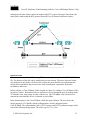
Topology
It is very important to have an accurate topology of the network that contains the ports to which
various components are connected, such as VLANs, routers, switches, gateways, and so on.
Having a well-documented topology will assist you in troubleshooting problems with the system.
You need to ensure that you have an accurate topology, access to all the network devices, and
terminal services for management of the Cisco CallManager.
Adding IP telephony to a new or existing network requires significant planning to ensure
success. Since real-time traffic has different requirements than data traffic, the network must be
designed with low latency and quality-of-service (QoS) in mind. As with any network that
carries mission-critical traffic, it is imperative that the network administrator maintains accurate,
detailed diagrams of the network topology. In a crisis situation it is important to know not just
the broad overview of the network, but also which ports are connected to network components,
such as routers, switches, Cisco CallManager servers, gateways, and other critical devices. It is
important to plan the network with redundancy and scalability in mind.
Caution: Cisco does not support using hubs for shared connectivity to the switches as they can
interfere with correct operation of the IP telephony system.
When working with switched networks, knowing the state of the spanning-tree for redundancy is
critical. The state of the network should be documented before any failure occurs.
© 2000 Cisco Systems, Inc.
4
Cisco IP Telephony Troubleshooting Guide for Cisco CallManager Release 3.0(1)
Documentation Checklist
Use the following checklist to be sure you have the proper documentation on your network
topology.
• Topology that shows all network devices and critical components with port/interface
numbers to which they are attached, and what VLAN (if applicable) to which they
belong. Special designations should be used for ports that are in trunking or channeling
mode.
• The root of the spanning-tree should be configured and all normally blocking ports
should be identified.
• Any WAN circuits should be identified with the amount of bandwidth (CIR in the case of
frame-relay).
Note: The Cisco IP Phone 7960 has a 10/100-switched network port and a 10/100 PC port. Cisco
does not support “cascading” phones off of the PC port. We do not recommend attaching both
the network and PC ports to a switch (thereby creating a physical loop in the network).
Any WAN interface will require special consideration, since this is a potential source of
congestion. Cisco IP Phones and gateways set the RTP stream IP precedence field to five,
however this only tags the RTP packet. It is up to the network administrator to ensure that the
network is configured for prioritization and call admission control so that the Voice over IP
(VoIP) traffic can be serviced with minimal delay and contention for resources. For additional
information on this topic, see:
http://www.cisco.com/warp/public/793/voip/
© 2000 Cisco Systems, Inc.
5
Cisco IP Telephony Troubleshooting Guide for Cisco CallManager Release 3.0(1)
Glossary of Terms
Following are some common terms and acronyms that may be used in this document.
Glossary
Acronym/Term
.cnf
µ-law (“mu-law”)
A-law
ACF
ANI
ARQ
B-Channel
Calling Search Space
CCAPi
CCO
CDR
Cisco IOS
Cluster
CMR
codec
D-Channel
DCF
DHCP
DN
Definition
Configuration file used by devices.
Companding technique commonly used in North America. µ-law is
standardized as a 64-kbps codec in ITU-T G.711.
ITU-T companding standard used in the conversion between analog
and digital signals in PCM systems. A-law is used primarily in European
telephone networks and is similar to the North American µ-law
standard.
Admission Confirm.
The calling number
Admission Request.
Bearer channel. In ISDN, a full-duplex, 64-kbps channel used to send
user data.
The Calling Search Space defines what directory numbers and route
patterns a given device can call. It is a grouping of partitions to look
through when making a call. For example, assume there are several
Partitions in a Calling Search Space named “Executive.” If a
Cisco IP Phone number is in the “Executive” Calling Search Space,
then when initiating a call, it looks for the example “NYInternationalCall,”
“NYLongDistance,” “NYLocalCall,” and “NY911” Partitions available to
search through. A Cisco IP Phone number that has a “Guest” Calling
Search Space, for example, might only be allowed to search through
“NYLocalCall” and “NY911” Partitions, so that if the user tries to dial an
international number, it won’t find a match and the call can’t be routed.
Call Control API. Used by Cisco IOS to handle VoIP call processing.
Cisco Connection Online (http://www.cisco.com). Provides the latest
information on Cisco products, technical support information, and
technical documentation.
Call Detail Record. Information about call origination, destination, and
duration, used to create billing records.
Cisco system software that provides common functionality, scalability,
and security for all products under the CiscoFusion architecture. Cisco
IOS allows centralized, integrated, and automated installation and
management of internetworks, while ensuring support for a wide variety
of protocols, media, services, and platforms.
Cisco CallManager cluster. A logical grouping of several Cisco
CallManager servers.
Call Management Records, also known as Diagnostic CDRs. Records
that contain the count of bytes sent, packets sent, jitter, latency,
dropped packets, and so on.
Coder-Decoder. A DSP software algorithm used to
compress/decompress speech or audio signals.
Data channel. Full-duplex, 16-kbps (BRI) or 64-kbps (PRI) ISDN
channel. Used for signaling and control.
Disengage Confirm.
Dynamic Host Configuration Protocol. Provides a mechanism for
allocating IP addresses dynamically so that addresses can be reused
when hosts no longer need them.
Directory Number. This is the phone number of an end device. It can be
a number assigned to a Cisco IP Phone, a Cisco IP SoftPhone, fax
© 2000 Cisco Systems, Inc.
6
Cisco IP Telephony Troubleshooting Guide for Cisco CallManager Release 3.0(1)
Glossary
DNIS
DNS
DRQ
DTMF
Flow
Full duplex
G.711
G.729
H.225
H.245
H.323
Half Duplex
Hookflash
ICCP
ISDN
Jitter
µ-law (“mu-law”)
MGCP
MTP
Partition
PBX
machine, or analog phone attached to a gateway. Examples include
1000, 24231, and so on.
Dialed Number Identification Service.
Domain Name System. System used in the Internet for translating
names of network nodes into addresses.
Disengage Request.
Dual tone multifrequency. Use of two simultaneous voice-band tones for
dialing (such as touch tone).
Stream of data traveling between two endpoints across a network (for
example, from one LAN station to another). Multiple flows can be
transmitted on a single circuit.
Capability for simultaneous data transmission from both a sending
station and a receiving station.
Describes the 64-kbps PCM voice coding technique. In G.711, encoded
voice is already in the correct format for digital voice delivery in the
PSTN or through PBXs. Described in the ITU-T standard in its G-series
recommendations.
Describes CELP compression where voice is coded into 8-kbps
streams. There are two variations of this standard (G.729 and G.729
Annex A) that differ mainly in computational complexity; both provide
speech quality similar to 32-kbps ADPCM. Described in the ITU-T
standard in its G-series recommendations.
An ITU standard that governs H.225 session establishment and
packetization. H.225 actually describes several different protocols:
RAS, use of Q.931, and use of RTP.
An ITU standard that governs H.245 endpoint control.
Extension of ITU-T standard H.320 that enables videoconferencing over
LANs and other packet-switched networks, as well as video over the
Internet.
Capability for data transmission in only one direction at a time between
a sending station and a receiving station. BSC is an example of a halfduplex protocol.
Short on-hook period usually generated by a telephone-like device
during a call to indicate that the telephone is attempting to perform a
dial-tone recall from a PBX. Hookflash is often used to perform call
transfer.
Intra-Cluster Control Protocol
Integrated Services Digital Network. Communication protocol, offered
by telephone companies, that permits telephone networks to carry data,
voice, and other source traffic.
The variation in the arrival times of voice packets.
Companding technique commonly used in North America. µ-law is
standardized as a 64-kbps codec in ITU-T G.711.
Media Gateway Control Protocol. A protocol for Cisco CallManager to
control VoIP gateways (MGCP endpoints).
Media Termination Point.
A Partition is a logical grouping of Directory Numbers and Route
Patterns with similar reachability characteristics. For simplicity, these
are usually named for their characteristic, such as "NYLongDistance",
"NY911", etc. When a DN or Route Pattern is placed into a certain
partition, this creates a rule for who can call that device or Route List.
Private Branch Exchange. Digital or analog telephone switchboard
located on the subscriber premises and used to connect private and
public telephone networks.
© 2000 Cisco Systems, Inc.
7
Cisco IP Telephony Troubleshooting Guide for Cisco CallManager Release 3.0(1)
Glossary
PRI
PSTN
Q.931
RAS
Route Filter
Route Group
Route List
Route Pattern
RRJ
RTP
SEP
Silence Suppression (Voice
Activation Detection)
SNMP
SQL
T1/CAS
PRI is Primary Rate Interface. Primary rate access consists of a single
64-Kbps D channel plus 23 (T1) or 30 (E1) B channels for voice or data.
Public Switched Telephone Network. General term referring to the
variety of telephone networks and services in place worldwide.
ITU standard that describes ISDN signaling. The H.225.0 standard uses
a variant of Q.931 to establish and disconnect H.323 sessions.
Registration, Admission, and Status protocol. Protocol used in the
H.323 protocol suite for discovering and interacting with a gatekeeper.
A route filter can be used not only to restrict dialing, but also to identify
a subset of a wildcard pattern (when using the @ wildcard in the North
American Dialing Plan). For example, it could be used to block the
dialing of 900 area codes. In can also be used in conjunction with
Partitions and Calling Search Spaces to set up complex rules. For
example, assume you have three user groups established, Executive,
Staff, and Guest. A Route Filter can allow the Executive user group to
dial international numbers; while the Staff user group can only dial local
numbers or long distance calls; and the Guest user group can only dial
local numbers, 911, and 800 numbers.
A Route Group is a list of one or more gateways or ports on gateways
that are seen as equal access. It is analogous to a trunk group in
traditional PBX terminology. For instance, you may have two PRI
circuits to the same carrier that can be used arbitrarily. A gateway (or a
particular port on a gateway) can only be added to one Route Group.
Formerly called Route Point, the Route List allows Cisco CallManager
to hunt through a list of Route Groups in a configured order of
preference. Multiple Route Lists can point to the same Route Groups.
A specific number or, more commonly, a range of dialed numbers that
will be used to route calls to a device (such as a Cisco Access DT-24+
Gateway or a voice-capable router) or indirectly via a Route List. For
example, 1XXX signifies 1000 through 1999. The ’X’ in 1XXX signifies a
single digit, a wildcard. There are other such wildcards (such as @, .,!,
etc). A Route Pattern does not have to be unique within a partition as
long as the Route Filter is different.
Registration Reject.
Real-Time Transport Protocol. One of the IPv6 protocols. RTP is
designed to provide end-to-end network transport functions for
applications transmitting real-time data, such as audio, video, or
simulation data, over Multicast or Unicast network services. RTP
provides services such as payload type identification, sequence
numbering, time stamping, and delivery monitoring to real-time
applications.
Selsius Ethernet Phone. Acronym that precedes MAC Addresses on
Cisco IP Phones, and represents a unique device identifier.
Silence Suppression allows a Cisco IP Phone to detect the absence of
audio and does not transmit packets over the network. The sound
quality may be slightly degraded but the connection may also use less
bandwidth. Silence Suppression is disabled by default.
Simple Network Management Protocol. Network management protocol
used almost exclusively in TCP/IP networks. SNMP provides a means
to monitor and control network devices, and to manage configurations,
statistics collection, performance, and security.
Structured Query Language. International standard language for
defining and accessing relational databases.
T1 is a digital WAN carrier facility, transmitting DS-1-formatted data at
© 2000 Cisco Systems, Inc.
8
Cisco IP Telephony Troubleshooting Guide for Cisco CallManager Release 3.0(1)
Glossary
T1/PRI
TCP
TFTP
Translation Pattern
UDP
Voice Activation Detection
(Silence Suppression)
VoIP
VLAN
1.544 Mbps through the telephone-switching network, using AMI or
B8ZS coding. CAS is a Channel Associated Signaling interface.
T1 is a digital WAN carrier facility, transmitting DS-1-formatted data at
1.544 Mbps through the telephone-switching network, using AMI or
B8ZS coding. PRI is Primary Rate Interface. Primary rate access
consists of a single 64-Kbps D channel plus 23 (T1) or 30 (E1) B
channels for voice or data.
Transmission Control Protocol. Connection-oriented transport layer
protocol that provides reliable full-duplex data transmission. TCP is part
of the TCP/IP protocol stack.
Trivial File Transfer Protocol. Simplified version of FTP that allows files
to be transferred from one computer to another over a network.
Used to translate called (DNIS) and calling (ANI) numbers before
routing the call. For example, a call may come in to a set of numbers
919 392-3XXX that need to be translated to a set of Cisco IP Phones
that are in the range of 2XXX. Cisco CallManager has a Translation
Pattern set up for 919 392-3XXX. This pattern translates the leading
919 392-3 simply to 2 while leaving the remaining digits intact. Then the
call is routed to the appropriate Cisco IP Phone. Translation Patterns
are used only for true translations and should not be used for simple
digit stripping and prefixing.
User Datagram Protocol. Connectionless transport layer protocol in the
TCP/IP protocol stack. UDP is a simple protocol that exchanges
datagrams without acknowledgments or guaranteed delivery, requiring
that error processing and retransmission be handled by other protocols.
UDP is defined in RFC 768.
Voice Activation Detection allows a Cisco IP Phone to detect the
absence of audio and does not transmit packets over the network. The
sound quality may be slightly degraded but the connection may also
use less bandwidth. VAD/Silence Suppression is disabled by default.
Voice over IP.
virtual LAN. Group of devices on one or more LANs that are configured
(using management software) so that they can communicate as if they
were attached to the same wire, when in fact they are located on a
number of different LAN segments. Because VLANs are based on
logical instead of physical connections, they are extremely flexible.
© 2000 Cisco Systems, Inc.
9
Cisco IP Telephony Troubleshooting Guide for Cisco CallManager Release 3.0(1)
Tools and Utilities to Monitor and Troubleshoot Cisco CallManager
This section addresses the tools and utilities to configure, monitor and troubleshoot
Cisco CallManager.
Cisco CallManager Administration Details
Cisco CallManager Administration provides version information for the system, database and
other components. On the opening page, press the Details button and write down the versions in
use.
A more detailed explanation of Cisco CallManager Administration is available at the following
location:
http://www.cisco.com/univercd/cc/td/doc/product/voice/c_callmg/3_0/index.htm
© 2000 Cisco Systems, Inc.
10
Cisco IP Telephony Troubleshooting Guide for Cisco CallManager Release 3.0(1)
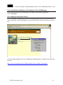
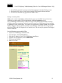
Microsoft Performance
Performance (Monitor) is a Windows 2000 server application that can display the activities and
status of your Cisco CallManager system. It reports both general and specific information in real
time. You can use Windows 2000 Performance to collect and display system and device statistics
for any Cisco CallManager installation. This administrative tool allows you to gain a full
understanding of a system without studying the operation of each of its components.
You can use Performance to monitor a variety of system variables in real time. After adding the
Cisco CallManager parameters, you can define the terms under which Cisco CallManager will
display statistics generated by the system. For example, you can monitor the number of calls in
progress at any time, or the number of calls currently passing through a specific gateway.
Performance shows both general and Cisco CallManager-specific status information in real-time.
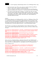
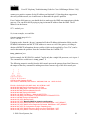
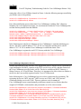
View Report
Click the View
button and then the
Add button and
make selections on
the dialog box (press
and hold the Ctrl key
to select multiple
items in the list).
Click Add and then
Close and view the
report in the window.
Add Counters
Click the Add
button. The Add
Counters dialog
box is displayed.
Opening Microsoft Performance
To open Performance on the server PC running Cisco CallManager, click Start > Settings >
Control Panel > Administration Tools > Performance.
Customizing Performance
The Performance monitor must be customized to view the Cisco CallManager-related parameters
that you wish to monitor. Choose the object, counter, and instance you want to include. Please
refer to the Remote Serviceability documentation for instructions on how to use objects and
counters to customize Microsoft Performance for Cisco CallManager operations.
http://www.cisco.com/univercd/cc/td/doc/product/voice/c_callmg/3_0/service/index.htm
© 2000 Cisco Systems, Inc.
11
Cisco IP Telephony Troubleshooting Guide for Cisco CallManager Release 3.0(1)
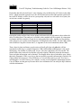
Microsoft Event Viewer
Microsoft Event Viewer is a Windows NT Server application that displays system, security, and
application events (including Cisco CallManager) for the Windows NT Server. If a service
(including TFTP) cannot read the database (where it gets the trace configuration), it will add
errors to the Event Viewer. The Event Viewer is the only place where these types of errors will
appear. The following illustration shows the application logs running on a Windows NT Server.
Opening Event Viewer
To open the Event Log on the server PC running Cisco CallManager, click Start > Settings >
Control Panel > Administrative Tools > Event Viewer. The Event Viewer provides error logs
for System, Security, and Applications. Cisco CallManager errors are logged under the
Application log.
© 2000 Cisco Systems, Inc.
12
Cisco IP Telephony Troubleshooting Guide for Cisco CallManager Release 3.0(1)
Detailed Information about Events
You can double-click an event in the log to learn more information about the event.
SDI Trace
SDI traces are local log files. The IP address, TCP handle, device name or the time stamp can be
used when reviewing the SDI trace to monitor the occurrence or the disposition of a request. This
device name could be tracked back to the building of the file, which shows the device pool and
model. The device pool and model can be tracked back to the building of the configuration file
prototype, which will list the network address of the Cisco CallManager(s) and the TCP
connection port.
When observing SDI traces, notice that C++ class and routine names are included with most
trace lines. Most routines associated with the serving of a particular request include the thread ID
in a standard format.
SDI traces will be explained in detail in the case studies in the appendices.
SDI Trace Output
SDI traces generate files (for example, CCM000000000) that store traces of Cisco CallManager
activities. These traces provide information about the Cisco CallManager initialization process,
registration process, KeepAlive process, call flow, digit analysis, and related devices such as
Cisco IP Phones, Gateways, Gatekeepers, and more. This information can help you isolate
problems when troubleshooting Cisco CallManager. To properly track the information you
© 2000 Cisco Systems, Inc.
13
Cisco IP Telephony Troubleshooting Guide for Cisco CallManager Release 3.0(1)
need—and only the information you need—it’s important to understand how to set the options
on the trace configuration interface.
The trace files are stored in the following default location: C:\Program Files\cisco\bin. A new
trace file is started each time Cisco CallManager restarts, or when the designated number of lines
has been reached.
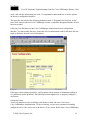
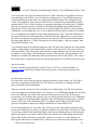
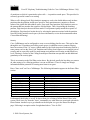
Following is an illustration of the Cisco CallManager Administration trace configuration
interface. You must enable the trace, choose the level on information needed, and check the user
mask to obtain the desired level of information.
If the trace is not configured properly, it will generate a large amount of information making it
very difficult to isolate problems. The following section explains how to properly configure a
useful trace.
Configuring Traces
Traces are composed of user mask flags (also known as bits) and trace levels. Open
Cisco CallManager Administration. To turn on tracing, set your trace parameters (including
configured service, bits, and so on) in the Service>Trace screen. Refer to the Cisco CallManager
© 2000 Cisco Systems, Inc.
14
Cisco IP Telephony Troubleshooting Guide for Cisco CallManager Release 3.0(1)
documentation for complete information about turning tracing on and off, and for descriptions of
the User Masks and Levels for each configured service, and more.
http://www.cisco.com/univercd/cc/td/doc/product/voice/c_callmg/3_0/admin_gd/admin_gd/inde
x.htm
Following are two examples of trace mask bits that would be enabled based on the particular
problem.
•
•
For normal message debugging, turn on subsystem bits 5, 6, 7, 8, 11, and 12
For debugging gateways, turn on subsystem bits 3,4,5,6,7,8,9,11,12,13
Following are two examples of desired trace levels based on the particular problem
•
•
For normal debugging, the trace level should be set to SDI_LEVEL_ARBITRARY
For normal running system, the trace level should be set to SDI_LEVEL_ERROR
SDL Trace
Cisco engineers use SDL traces to find the cause of an error. You are not expected to understand
the information contained in an SDL trace. However, while working with TAC, you may be
asked to enable the SDL trace and provide it to the TAC. SDL trace files can be saved to local
directories, the Windows NT Event Viewer, and CiscoWorks 2000. To avoid any performance
degradation on the server, be sure that after the trace has been captured, you turn off SDL
tracing.
SDL trace provides a C interface to trace and alarms. Alarms are used to inform the
administrator of unexpected events, such as being unable to access a file, database, Winsock, or
being unable to allocate other operating system resources.
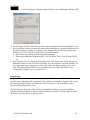
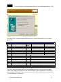
Enabling SDL Trace
SDL traces are enabled in the Service > Service Parameter area in
Cisco CallManager Administration. Remember that these traces should be turned on only when
requested by a TAC engineer. Note the values chosen to turn on the SDL trace in the following
illustration.
© 2000 Cisco Systems, Inc.
15
Cisco IP Telephony Troubleshooting Guide for Cisco CallManager Release 3.0(1)
Once SDL traces are enabled, collect the traces. If the traces are being sent to the local drive,
then you can retrieve them in the Cisco\Trace subdirectory. Alternatively, the trace files can be
sent to an event log or to CiscoWorks 2000.
SDL flag bits described in the following table are set in the Service > Service Parameters area
in Cisco CallManager Administration. Following are two examples of desired values based on
the particular problem.
•
•
The recommended value for normal call debugging is SdlTraceTypeFlags=0x00000b04
The recommended value for low level debugging or debugging gateways is
SdlTraceTypeFlags=0x00004b05
© 2000 Cisco Systems, Inc.
16
Cisco IP Telephony Troubleshooting Guide for Cisco CallManager Release 3.0(1)
SdlTraceTypeFlags Definitions
SDLTraceTypeFlag
Value
traceLayer1
= 0x00000001
TraceDetailLayer1
= 0x00000002
TraceSdlLinkAdmin
= 0x00000004
traceUnused
= 0x00000008
traceLayer2
= 0x00000010
traceLayer2Interface
= 0x00000020
traceLayer2TCP
= 0x00000040
TraceDetailLayer2
= 0x00000080
traceLayer3
= 0x00000100
traceCc
= 0x00000200
traceMiscPolls
= 0x00000400
traceMisc
= 0x00000800
traceMsgtrans
= 0x00001000
traceUuie
traceGateway
= 0x00002000
= 0x00004000
Definition
All Layer 1 trace on
Detail Layer 1 trace on
Trace inter-Cisco CallManager links within a cluster
Not used
All Layer 2 trace on
Layer 2 interface trace on
Layer 2 TCP trace on
More detail dump of Layer 2 Frames.
All Layer 3 trace on
All call control trace on
Trace miscellaneous polls
Miscellaneous trace on (Database signals)
Message Translation signals (TranslateIsdnToSdlReq,
TranslateIsdnToSdlRes TranslateSdlToIsdnReq,
TranslateSdlToIsdnRes)
UUIE output trace on
Gateway signals
Data bits described in the following table are set in the Service > Service Parameters area in
Cisco CallManager Administration. Following are two examples of desired values based on the
particular problem.
•
•
The recommended value for normal system debugging is SdlTraceDataFlags=0x110
The recommended value when tracking problems with SDL links is 0x13D (noncompacted trace; if a compact trace is desired, bit 0x200 must be set. It can be set in
combination with any other bits)
SDLTraceDataFlags Definitions
SDLTraceDataFlag
Value
TraceSdlLinkState
= 0x001
TraceSdlLowLevel
= 0x002
TraceSdlLinkPoll
TraceSdlLinkMsg
traceRawData
TraceSdlTagMap
traceCreate
TraceNoPrettyPrint
= 0x004
= 0x008
= 0x010
= 0x020
= 0x100
= 0x200
Definition
Enable trace of SDL Link Initialization
Enable tracing of low-level SDL events, for example, fileOpen,
socket events, and so on
Enable tracing of SDL Link Poll message
Enable tracing of SDL Link Message
Enable raw signal data trace on all signals
Enable tag mapping
Enable process create and stop traces
Disable pretty printing of trace files
Disk Space Warning
IMPORTANT: Be advised that information obtained from this interface could be very detailed,
and therefore consume a large amount of disk space. For this reason, we advise you to turn on
the trace file for a specific amount of time, then review the information and turn off the trace.
© 2000 Cisco Systems, Inc.
17
Cisco IP Telephony Troubleshooting Guide for Cisco CallManager Release 3.0(1)
Sniffer Trace
A Sniffer is a software application that monitors IP traffic on a network and provides information
in the form of a trace. Sniffer traces provide information about the quantity and type of network
traffic on your network. TCP/IP or UDP packets are protocols utilized by Cisco CallManager
and endpoint devices such as phones and gateways. Sniffer traces can also help you identify high
levels of broadcast traffic that could result in voice audio problems or dropped calls. Common
Sniffer applications include Network Associates SnifferPro, Hewlett Packard Internet Advisor,
and W&G Domino. Domino offers sniffing hardware and software solutions and a network
analyzer. If you want to use Domino, we recommend using the analysis software to evaluate a
captured sniffer file (such as from the SnifferPro application).
Sniffer Trace Applications
Use the following links to learn more about some available sniffer trace applications. Any sniffer
application will work with Cisco CallManager.
•
•
•
Network Associates SnifferPro: http://www.sniffer.com/
Hewlett Packard Network Analyzer:
http://www.hp.com/rnd/products/netman/netmgt.htm
W&G Domino Analyzer: http://www.wwgsolutions.com/products/domino/domino.html
Call Detail Records (CDR) and Call Management Records (CMR)
Call Detail Record (CDR) is a reporting option that logs every call made (or attempted) from any
Cisco IP Phone. There are two kinds of CDRs—basic CDRs and Diagnostic CDRs, or CMRs.
Once enabled, you can open CDRs or Diagnostic CDRs (CMRs) in the SQL Server Enterprise
Manager. CDR files are saved in a SQL database that can be exported to nearly any application,
including Microsoft Access or Excel.
CDR records contain information needed to generate billing records. In a distributed
environment, all CDR data is collected in a central location, or a set of locations. The failure of a
Cisco CallManager node does not make the CDR data associated with that node unavailable,
since the data is no longer stored on the Cisco CallManager disk as a flat file, but is instead
stored in a central database in tables.
If the Cisco CallManager fails before any records are written, then no record of the call will
exist. This means that no record will be written for calls that are active on a given
Cisco CallManager when it fails before the calls terminate.
Refer to the Appendix in the back of this book for detailed information about CDRs and CMRs.
The information provided includes:
•
•
•
Reading and Writing Records
Known Issues
List of record types generated
© 2000 Cisco Systems, Inc.
18
Cisco IP Telephony Troubleshooting Guide for Cisco CallManager Release 3.0(1)
•
•
•
List of fields contained in each record and a description of what that field represents
Description of the types of calls logged, and the fields logged with each of them
List of cause codes that may appear in the CDR records
Enabling or Disabling CDRs
CDR record creation is disabled by default when the system is installed. If you wish to have
CDR data, you must enable CDRs in the Service > Service Parameters area of
Cisco CallManager Administration. CDR processing can be enabled and disabled at any time
while the system is in operation. You do not need to restart Cisco CallManager for the enabling
or disabling of CDRs to take effect. The system will respond to all changes within a few seconds.
CMR or diagnostic data is enabled separately from CDR data. CMR data will not be generated
unless both CDRs and Call Diagnostics are enabled, but CDR data may be generated and logged
without CMR data.
Use the following steps to enable CDRs.
1. Open Cisco CallManager Administration.
2. Select Service > Service Parameters.
3. Select the IP address of your Cisco CallManager installation.
4. From the list of Parameters, select CDREnabled.
5. Define type as boolean.
6. Select T for True.
© 2000 Cisco Systems, Inc.
19
Cisco IP Telephony Troubleshooting Guide for Cisco CallManager Release 3.0(1)
7. Update.
Result: Call Detail Records will start logging immediately.
Caution: Tracing voice connectivity requires that CDR logging be enabled on every
Cisco CallManager installation in a cluster.
CDRs
CDRs provide basic information that can help you understand the more detailed information
contained in SDI traces. Basic CDRs provide information such as the calling number, called
number, originating IP address, destination IP address, call duration, and so on. CDRs can help
you troubleshoot phone problems. For example, if a user reports a problem with a call occurring
at a specific time, you can consult the CDRs that occurred around the time indicated to learn
additional information about that call and others. CDRs are commonly used for billing.
Diagnostic CDRs (Also Known As CMRs)
Diagnostic CDRs provide detailed call information, such as the number of packets sent, received,
and lost, the amount of jitter and latency, and so on. This level of detail can provide explanations
for some problems, such as one-way audio. For example, a one-way audio problem is indicated if
a packet size of 10,000 is sent, but the received size is only 10.
© 2000 Cisco Systems, Inc.
20
Cisco IP Telephony Troubleshooting Guide for Cisco CallManager Release 3.0(1)
Problem Categories
This section addresses some common problem categories that may occur with
Cisco CallManager and related devices. Each problem category provides suggestions for the
troubleshooting tools you should use to help isolate the problem. This document provides general
categories of potential problems and suggestions about how to troubleshoot those problems. It
does not provide an exhaustive list of problems and resolutions. If you encounter a problem that
cannot be resolved using the tools and utilities described in this document, consult the
Cisco Technical Assistance Center (TAC) for assistance. Be sure to have available the
Cisco CallManager Administration Details, plus the diagnostic information (traces, etc.) you
have gathered up to the point of calling the TAC.
Voice Quality
Voice quality issues include lost or distorted audio during phone calls. Common problems can be
breaks in the sound which cause the audio to be intermittent (like broken words), or the presence
of odd noises that distort the audio, such as echo, or effects that cause spoken words to sound
watery or robotic. One-way audio, that is, a conversation between two people where only one
person can hear anything, is not actually a voice quality issue, but will be discussed later in this
section.
One or more of the following components could cause audio problems:
• Gateway
• Phone
• Network
To properly troubleshoot voice quality issues, you must consider the infrastructure and all the
devices for drops and delays.
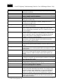
Lost or Distorted Audio
One of the most common problems encountered is a breaking up of audio (often described as
garbled speech, or a loss of syllables within a word or sentence). There are two common causes
for this: packet loss and/or jitter. Packet loss means that audio packets do not arrive at their
destination because they were dropped or arrived too late to be useful. Jitter is the variation in the
arrival times of packets. In the ideal situation, all VoIP packets from one phone to another would
arrive exactly at a rate of 1 every 20 ms. Notice that this does not mention how long it takes for a
packet to get from point A to point B, simply the variation in the arrival times. There are many
sources of variable delay in a real network. Some of these cannot be controlled, and some can.
Variable delay cannot be eliminated entirely in a packetized voice network. Digital Signal
Processors (DSPs) on phones and other voice-capable devices are designed to buffer some of the
audio, in anticipation of variable delay. This “dejittering” is done only when the audio packet has
reached its destination and is now ready to be put into a conventional audio stream (to be played
out into the user’s ear to be sent to the PSTN via a digital PCM stream). The
Cisco IP Phone 7960 can buffer as much as one second of voice samples. The jitter buffer is
adaptive, meaning if a burst of packets is received, the Cisco IP Phone 7960 can play them out in
an attempt to control the jitter. The network administrator needs to minimize the variation
© 2000 Cisco Systems, Inc.
21
Cisco IP Telephony Troubleshooting Guide for Cisco CallManager Release 3.0(1)
between packet arrival times by applying quality-of-service (QoS) and other measures in
advance (especially if calls cross a wide-area network).
When faced with a lost or distorted audio problem, the first thing to do is to try to isolate the path
of the audio. Try to identify each network device (switches and routers) in the path of the call’s
audio stream. Keep in mind that the audio may be between two phones, or between a phone and
a gateway, or it could have multiple legs (from a phone to a transcoding device and from there to
another phone). Try to identify if the problem occurs only between two sites, only through a
certain gateway, on a certain subnet, and so on. This will help narrow down which devices you
need to look at more carefully. Next, if is often best to disable silence suppression (also known
as Voice Activation Detection or VAD) if this hasn’t been done already. This mechanism does
save bandwidth by not transmitting any audio when there is silence, but may cause noticeable
clipping at the beginning of words that may be unacceptable. You can disable this in
Cisco CallManager Administration, under Service > Service Parameters. From there, select the
server and the Cisco CallManager service. Then set SilenceSuppressionSystemWide to “F”
(alternatively you can set SilenceSuppressionWithGateways to “F”, but this does not apply to
H.323 gateways or MGCP gateways). When in doubt, turn both off by selecting the Value F for
each.
If a network analyzer is available, then a monitored call between two phones should have 50
packets per second (or 1 packet every 20 ms) when silence suppression is disabled. With proper
filtering, it should be possible to identify if packets are being lost or delayed excessively.
© 2000 Cisco Systems, Inc.
22
Cisco IP Telephony Troubleshooting Guide for Cisco CallManager Release 3.0(1)
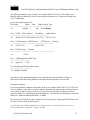
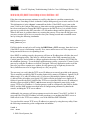
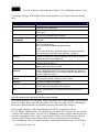
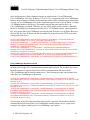
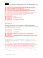
Remember that delay by itself won’t cause clipping, only variable delay will. Notice in the table
below, which represents a perfect trace, the arrival times between the audio packets (which will
have an RTP header), will be 20 ms. In a poor quality call (such as a call with a lot of jitter), the
arrival times would vary greatly.
A Perfect Trace
Packet Number
1
2
3
4
5
Time – absolute (ms)
0
0.02
0.04
0.06
0.08
Time – delta (ms)
20
20
20
20
Placing the packet analyzer into various points in the network will help narrow down where the
delay is coming from. If no analyzer is available, other methods will be required. It is important
to examine interface statistics of each device in the path of the audio. Another tool for tracking
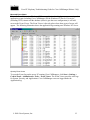
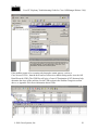
calls with poor voice quality is the Diagnostic Call Detail Records (CDRs). See the CDR section
in the Problem Categories section above, or Appendix D for more information about CDRs.
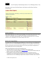
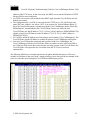
Then values for jitter and latency can be retrieved for all calls (but only after the call has
terminated). Following is a sample Diagnostic CDR (CallDetailRecordDiagnostic is the actual
table name). The number of packets sent, receive, lost, jitter, and latency are all recorded. The
globalCallID value can be used to find the call in the regular CDR table so that the disconnect
cause and other information can be obtained. The diagram below shows both tables open. Notice
that in the Diagnostic CDR, every device that can possibly report this information is included. So
if the problem is between two Cisco IP Phones, we see two table entries per call. If we have a
call through a Cisco IOS Gateway, for example, we only see the diagnostic information from the
Cisco IP Phone, not the gateway because there is no mechanism for it to notify the SQL database
with this information.
© 2000 Cisco Systems, Inc.
23
Cisco IP Telephony Troubleshooting Guide for Cisco CallManager Release 3.0(1)
i Button Help
The Cisco IP Phone 7960 provides another tool for diagnosing possible audio problems. On an
active call, you can press the i button twice rapidly and the phone will display an information
screen that contains packet receive and transmit statistics, as well as average and maximum jitter
counters. Note that on this screen, jitter is the average of the last 5 packets that arrived; the
maximum jitter is the high-water mark for the average jitter.
The most common sources for delay and packet loss are devices where a higher speed interface
feeds into a lower speed interface. For example: a router may have a 100 Mb fast Ethernet
interface connected to the LAN and a slow frame-relay, for example, connected to the WAN. If
the poor quality occurs only when communicating to the remote site (only the remote site may be
reporting the poor voice quality while in the other direction everything appears to be fine), then
the most likely causes of the problem include:
•
•
•
•
The router has not been properly configured to give the voice traffic priority over the data
traffic
There are too many calls active for the WAN to support (that is, there is no call admission
control to restrict the number of calls that can be placed)
There are physical port errors
There is congestion in the WAN itself
On the LAN, the most common problems are physical-level errors (such as CRC errors) caused
by faulty cables, interfaces, or by incorrectly configured devices (such as a port speed or duplex
© 2000 Cisco Systems, Inc.
24
Cisco IP Telephony Troubleshooting Guide for Cisco CallManager Release 3.0(1)
mismatch). Make sure that the traffic is not crossing any shared-media device, such as a hub.
There could also be situations where the traffic is taking a slower path through the network than
expected. If QoS has been configured correctly, then the possibility exists that there is no call
admission control. Depending on your topology, this can be accomplished through the use of
Locations in Cisco CallManager Administration configuration, or by using a Cisco IOS router as
a gatekeeper. In any case, you should always know how many calls could be supported across
your WAN. If possible, test this by disabling silence suppression as described earlier, then place
calls between the two sites. Do not place the calls on hold or on mute, since this will stop packets
from being transmitted. With the maximum number of calls across the WAN, the calls should all
have acceptable quality. Test to make sure that a fast busy is returned when trying to make one
more call.
Crackling
Another “poor quality” symptom may be a crackling, which is sometimes caused by a defective
power supply or some kind of strong electrical interference close to the phone. Try swapping the
power supply and moving the phone around.
Check Your Loads
You should also always check the phones and gateways to ensure the latest software loads are in
use. When in doubt, check CCO (Cisco Connection Online at www.cisco.com) for the latest
software loads, new patches, or release notes relating to the problem.
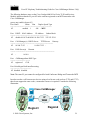
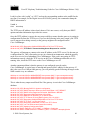
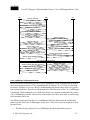
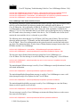
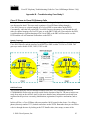
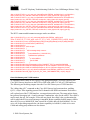
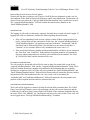
Echo
Echo (also known as “talker echo”) occurs when a talker’s speech energy, transmitted down the
primary signal path, is coupled into the receive path from the far end. The talker then hears his or
her own voice, delayed by the total echo path delay time.
John
Tx
Rx
Rx
Voice Network
Jane
Tx
In the diagram above, John’s voice (in blue) is being reflected back. This can happen but go
unnoticed in a traditional voice network because the delay is so low. To the user, it sounds more
like a side-tone than an echo. In a VoIP network, it will always be noticeable, since packetization
and compression always contribute enough delay. The important thing to remember is that the
cause of the echo is always with analog components and wiring. For instance, IP packets cannot
simply turn around and go back to the source at a lower audio level. The same is impossible on
digital T1/E1 circuits. So on a call from one Cisco IP Phone to another, there should never be
any problem. The only exception may be if one party is using a speakerphone that has the
volume set too high or some other situation where an audio loop is created.
When troubleshooting echo problems, make sure that the phones that are being tested or
examined are not using the speakerphone, and that they have the headset volume to reasonable
© 2000 Cisco Systems, Inc.
25
Cisco IP Telephony Troubleshooting Guide for Cisco CallManager Release 3.0(1)
levels (start with 50% of the maximum audio level). Most of the time, the problems will occur
when attaching to the PSTN by way of a digital or analog gateway. Cisco IP Phone users may
complain that they hear their own voice being reflected back to them. Now, although the true
source of the problem is almost always at the far end, it is nearly always impossible to change
anything in the PSTN. So the first step is to determine which gateway is being used. If a digital
gateway is in use, then it may be possible to add additional padding in the transmit direction
(towards the PSTN), in the hopes that the lower signal strength will yield less reflected energy.
Additionally, you can adjust the receive level so that any reflected audio is reduced even further.
It is very important to remember to make small adjustments at a time. Too much attenuation of
the signal will make the audio impossible to hear on both sides. Alternatively, you can contact
the carrier and request to have the lines checked. On a typical T1/PRI circuit in North America,
the input signal should be –15 dB. If the signal level is much higher (-5 dB, for example), then
echo will be the likely result.
A log should be kept of all calls that experience echo. The time of the problem, the source phone
number, and the number called should all be recorded. Gateways have a fixed time of 16 ms of
echo cancellation. If the delay in the reflected audio is longer than this, the echo chancellor will
be unable to work properly. This should not be an issue for local calls, and long distance calls
should have external echo chancellors built into the network at the Central Office. This is one of
the reasons why it is important to note the external phone number of a call that experiences echo.
Check Your Loads
Gateway and phone loads should be verified. Check CCO (Cisco Connection Online at
www.cisco.com) for the latest software loads, new patches, or release notes relating to the
problem.
One-Way Audio or No Audio
One-way audio occurs when one person cannot hear another person during a call. This can be
caused by an improperly configured Cisco IOS Gateway, a firewall, or a routing or default
gateway problem, among other things.
There are a number of causes for one-way audio or no audio during a call. The most common
cause is an improperly configured device. For instance, Cisco CallManager handles the call setup
for a Cisco IP Phone. The actual audio stream occurs between the two Cisco IP Phones (or
between the Cisco IP Phone and a gateway). So it is entirely possible that the Cisco CallManager
is able to signal to a destination phone (making it ring) when the phone originating the call does
not have an IP route to the destination phone. A common cause for this is when the default
gateway in the phone is improperly configured manually or on the DHCP server.
If a call consistently has one-way audio, take a PC that is on the same subnet as the phone and
has the same default gateway and try to ping the destination Cisco IP Phone. Then take a PC that
is on the same subnet as the destination phone (with the same default gateway as the destination
phone) and ping the source phone. Both of those tests should work. Other things can affect the
audio traffic include a firewall or packet filter (such as access lists on a router) that may be
blocking the audio in one or both directions. If the one-way audio occurs only through a voice© 2000 Cisco Systems, Inc.
26
Cisco IP Telephony Troubleshooting Guide for Cisco CallManager Release 3.0(1)
enabled Cisco IOS Gateway, then check the configuration carefully. IP routing must be enabled
(look at the configuration to make sure that “no ip routing” is not found near the beginning of the
configuration). Also, make sure that if you’re using RTP header compression to save bandwidth
across the WAN, that it is enabled on each router carrying voice traffic that attaches to the WAN
circuit. There should not be a situation where the RTP header is compressed on one end but
cannot be de-compressed on the other side of the WAN. A sniffer is a very useful tool when
troubleshooting one-way audio problems, since you can then verify that the phone or gateway is
actually sending or receiving packets. Diagnostic Call Detail Records (CDRs) are useful for
determining if a call is experiencing one-way audio since they log transmitted and received
packets (see “Lost or Distorted Audio” section). You can also press the i button twice quickly
on a Cisco IP Phone 7960 during an active call to view details about transmitted and received
packets.
Note: When a call is muted, no packets will be transmitted from the phone that has pressed the
mute button. The Hold button stops the audio stream, so no packets are sent in either direction.
When the Hold button is released, all the packet counters are reset. Remember that Silence
Suppression must be disabled on both devices for the TX and RX counters to stay equal.
Disabling Silence Suppression system-wide will not affect Cisco IOS Gateways.
MTP and One-Way Audio
If you are using Media Termination Point (MTP) in a call (to support supplementary services
such as hold and transfer with H.323 devices that do not support H.323 version 2), check to see if
the MTP allocated is working correctly. Cisco IOS routers support H.323 version 2 beginning in
release 11.3(9)NA and 12.0(3)T. Starting with Cisco IOS release 12.0(7)T, the optional H.323
Open/Close LogicalChannel is supported, so that software-based MTP is no longer required for
supplementary services.
The MTP device, as well as Conference Bridge and Transcoder, will bridge two or more audio
streams. If the MTP, Conference Bridge, or Transcoder is not working properly, one-way audio
or audio loss might be experienced. Shut down MTP to find out if MTP is causing the problem.
Phone Resets
Phones will power cycle or reset for two reasons: 1) TCP failure connecting to
Cisco CallManager, or 2) failure to receive an acknowledgement to the phone’s KeepAlive
messages.
Steps for troubleshooting phone resets:
1. Check the phones and gateways to ensure that you are using the latest software loads.
2. Check CCO (Cisco Connection Online at www.cisco.com) for the latest software loads, new
patches, or release notes relating to the problem.
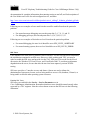
3. Check the Event Viewer for instances of phone(s) resetting. Phone resets are considered
Information events, as shown in the following illustration.
© 2000 Cisco Systems, Inc.
27
Cisco IP Telephony Troubleshooting Guide for Cisco CallManager Release 3.0(1)
4. Look for these and any errors that may have occurred around the time that the phone(s) reset.
5. Start an SDI trace and try to isolate the problem by identifying any common characteristics in
the phones that are resetting. For example, check whether they are all located on the same
subnet, same VLAN, and so on. Look at the trace and determine:
• If the resets occur during a call or happen intermittently
• If there any similarities of phone model – Cisco IP Phone 7960, Cisco IP Phone 30VIP,
etc.
6. Start a Sniffer trace on a phone that frequently resets. After it has reset, look at the trace to
determine if there are any TCP retries occurring. If so, this indicates a network problem. The
trace may show some consistencies in the resets, such as the phone resetting every seven
days. This might indicate DHCP lease expiration every seven days (this value is userconfigurable; could be every two minutes, etc.).
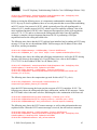
Dropped Calls
Dropped calls occur when a call is prematurely terminated. You can use CDRs to determine the
possible cause of dropped calls, particularly if the problem is intermittent. Dropped calls can be
the result of a phone or gateway resetting (see above section) or a circuit problem, such as
incorrect PRI configuration or error.
The first step is to determine if this problem is isolated to one phone or a group of phones.
Perhaps the affected phones are all on a particular subnet or location. The next step is to check
the Event Viewer for phone or gateway resets.
© 2000 Cisco Systems, Inc.
28
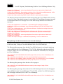
Cisco IP Telephony Troubleshooting Guide for Cisco CallManager Release 3.0(1)
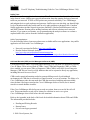
There should be one Warning and one Error message for each phone that resets. In this case, the
problem is often that the phone cannot keep its TCP connection to the Cisco CallManager alive,
so the Cisco CallManager resets the connection. This may be because a phone was turned off or
there may be a problem in the network. If this is an intermittent problem, it may be useful to use
Microsoft Performance to record phone registrations.
© 2000 Cisco Systems, Inc.
29
Cisco IP Telephony Troubleshooting Guide for Cisco CallManager Release 3.0(1)
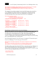
If the problem seems to be occurring only through a certain gateway, such as a
Cisco Access DT-24+, then the best course of action is to enable tracing and/or view the Call
Detail Records (CDR). The CDR files will give a Cause Of Termination (COT) that may help
determine the cause of the problem. See the CDR section in the Problem Categories section
above, or Appendix D for more information about CDRs.
© 2000 Cisco Systems, Inc.
30
Cisco IP Telephony Troubleshooting Guide for Cisco CallManager Release 3.0(1)
The disconnect cause values (origCause_value and destCause_value — depending on which side
hung up the call), map to Q.931 disconnect cause codes (in decimal) that can be found at
http://www.cisco.com/univercd/cc/td/doc/product/software/ios113ed/dbook/disdn.htm. In the
example above, cause 16 refers to a normal call clearing. If the call is going out a gateway to the
PSTN, then the CDR can be used to determine which side is hanging up the call. Much of the
same information can be obtained by enabling tracing on the Cisco CallManager. Use the trace
tool only as a last resort or if the network is not yet in production.
Check Your Loads
As with any problem, check the phone and gateway loads and CCO (Cisco Connection Online at
www.cisco.com) for the latest software loads, new patches, or release notes relating to the
problem.
Cisco CallManager Feature Issues
Problems may occur with features that are used in conjunction with Cisco CallManager, such as
Conference Bridge or Media Termination Point. Some feature problems can be caused by
configuration errors or lack of resources. For example, users may not be able to conference calls
if the specified number of Ad Hoc conference resources has been exceeded. The result would be
a dropped call when the user attempted to initiate the conference feature. This could appear to be
a Cisco CallManager feature issue, when in fact it is a problem with the number of available
conference resources. The number of times a conference resource was required but not available
is one of the counters logged in Microsoft Performance. The same behavior would occur if there
are conference resources available, but the conferencing service had stopped.
Codec/Regions: Codec Mismatch
If a user gets a reorder tone when going off-hook, it could be the result of codec disagreement
between regions. Verify that both call ends support at least one common codec (for example,
G.711). If not, you will need to use transcoders.
A region specifies the range of supported codecs that can be used with each of the other regions.
Every device belongs to a region.
Note: Codec negotiation with a Cisco IOS router is not supported.
For example, Region1<->Region2 = G.711, means that a call between a device in Region1 and a
device in Region2 can use G.711 or any other supported codec that requires the same or less
bandwidth as G.711 (any supported codecs within G.711, G.729, G.723, and so on).
Note: The following codecs are supported for each device:
Cisco IP Phone 7960 — G.711A-law/µ-law, G.729AnnexB
Cisco IP Phone SP12 series and VIP 30 — G.711A-law/µ-law, G.723.1
Cisco Access Gateway DE30 and DT-24+ — G.711A-law/µ-law, G.723.1
© 2000 Cisco Systems, Inc.
31
Cisco IP Telephony Troubleshooting Guide for Cisco CallManager Release 3.0(1)
Locations
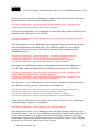
If a user gets a reorder tone after dialing a number, it could be because the Cisco CallManager
bandwidth allocation for the location of one of the call end devices has been exceeded (less than
24k). Cisco CallManager checks for 24k available bandwidth for each device before making a
call. If less than 24k bandwidth is available, Cisco CallManager will not setup the call and the
user will hear a reorder tone.
12:42:09.017 Cisco CallManager|Locations:
Orig=1 BW=12 Dest=0 BW=-1 (-1 implies infinite bw
available)
12:42:09.017 Cisco CallManager|StationD - stationOutputCallState tcpHandle=0x4f1ad98
12:42:09.017 Cisco CallManager|StationD - stationOutputCallInfo CallingPartyName=,
CallingParty=5003, CalledPartyName=, CalledParty=5005, tcpHandle=0x4f1ad98
12:42:09.017 Cisco CallManager|StationD - stationOutputStartTone: 37=ReorderTone
tcpHandle=0x4f1ad98
Once the call is established, the Cisco CallManager will subtract bandwidth from the locations
depending on the codec used in that call. If the call is using G.711, Cisco CallManager will
subtract 80k; if the call is using G.723, Cisco CallManager will subtract 24k; if the call is using
G729, Cisco CallManager will subtract 24k.
Conference Bridge
Use the following information to help troubleshooting a “No Conference Bridge available”
problem. This could be either software or a hardware problem.
First, check to see if you have any available Conference Bridge resources registered with
Cisco CallManager (either software or hardware). To do so, you can use Microsoft Performance
to check the number of “Unicast AvailableConferences.”
The Cisco IP Voice Media Streaming application performs the conference bridge function. One
software installation of Cisco IP Voice Media Streaming will support 16 Unicast Available
Conferences (3 people/conference), as shown in the following trace.
10:59:29.951 Cisco CallManager|UnicastBridgeControl - wait_capabilities_StationCapRes - Device=
CFB_kirribilli - Registered - ConfBridges= 16, Streams= 48, tcpHandle=4f12738
10:59:29.951 Cisco CallManager|UnicastBridgeManager - UnicastBridgeRegistrationReq - Device
Registration Complete for Name= Xoð´ ô%ð´ - DeviceType= 50, ResourcesAvailable= 16,
deviceTblIndex= 0
One E1 port (WS-X6608-E1 card contains 8x E1 ports) provides five Unicast Available
Conferences (max conference size = 6), as shown in the following trace.
11:14:05.390 Cisco CallManager|UnicastBridgeControl - wait_capabilities_StationCapRes - Device=
CFB00107B000FB0 - Registered - ConfBridges= 5, Streams= 16, tcpHandle=4f19d64
11:14:05.480 Cisco CallManager|UnicastBridgeManager - UnicastBridgeRegistrationReq - Device
Registration Complete for Name= Xoð´ ô%ð´ - DeviceType= 51, ResourcesAvailable= 5,
deviceTblIndex= 0
© 2000 Cisco Systems, Inc.
32
Cisco IP Telephony Troubleshooting Guide for Cisco CallManager Release 3.0(1)
The following hardware trace on the Cisco Catalyst 6000 8 Port Voice T1/E1 and Services
Module, indicates that the E1 port 4/1 in the card has registered as a Conference Bridge with
Cisco CallManager.
greece-sup (enable) sh port 4/1
Port Name
Status Vlan
Duplex Speed Type
----- ------------------ ---------- ---------- ------ ----- -----------4/1
enabled 1
full - Conf Bridge
Port DHCP MAC-Address
IP-Address
Subnet-Mask
-------- ------- ----------------- --------------- --------------4/1 disable 00-10-7b-00-0f-b0 10.200.72.31 255.255.255.0
Port Call-Manager(s) DHCP-Server TFTP-Server Gateway
-------- ----------------- --------------- --------------- --------------4/1 10.200.72.25
10.200.72.25 Port DNS-Server(s) Domain
-------- ----------------- ------------------------------------------------4/1 0.0.0.0
Port CallManagerState DSP-Type
-------- ---------------- -------4/1 registered
C549
Port NoiseRegen NonLinearProcessing
----- ---------- ------------------4/1 disabled disabled
Second, check the maximum number of users configured in the conference (Ad Hoc or
Meet-Me) to determine if the problem occurred because this number was exceeded.
Transcoding Problems
If you have installed a hardware transcoder in the Cisco Catalyst 6000 8 Port Voice T1/E1 and
Services Module, and it doesn’t work as expected (meaning you cannot make calls between two
users with no common codec), check to see if you have any available Transcoder resources
registered with Cisco CallManager (must be hardware). Use Microsoft Performance to check the
number of “MediaTermPointsAvailable” available.
One E1 port (WS-X6608-E1 card contains 8x E1 ports) provides Transcoder/MTP resources for
16 calls, as shown in the following trace.
11:51:09.939 Cisco CallManager|MediaTerminationPointControl - Capabilities Received - Device=
MTP00107B000FB1 - Registered - Supports 16 calls
© 2000 Cisco Systems, Inc.
33
Cisco IP Telephony Troubleshooting Guide for Cisco CallManager Release 3.0(1)
The following hardware trace on the Cisco Catalyst 6000 8 Port Voice T1/E1 and Services
Module, indicates that the E1 port 4/2 in the card has registered as an MTP/transcoder with
Cisco CallManager.
greece-sup (enable) sh port 4/2
Port Name
Status Vlan
Duplex Speed Type
----- ------------------ ---------- ---------- ------ ----- -----------4/2
enabled 1
full - MTP
Port DHCP MAC-Address
IP-Address
Subnet-Mask
-------- ------- ----------------- --------------- --------------4/2 disable 00-10-7b-00-0f-b1 10.200.72.32 255.255.255.0
Port Call-Manager(s) DHCP-Server TFTP-Server Gateway
-------- ----------------- --------------- --------------- --------------4/2 10.200.72.25
10.200.72.25 Port DNS-Server(s) Domain
-------- ----------------- ------------------------------------------------4/2 0.0.0.0
Port CallManagerState DSP-Type
-------- ---------------- -------4/2 registered
C549
Port NoiseRegen NonLinearProcessing
----- ---------- ------------------4/2 disabled disabled
Note: The same E1 port cannot be configured for both Conference Bridge and Transcoder/MTP
In order to make a call between two devices using a low bit rate code (such as G.729 and G.723)
that do not support the same codec, a transcoder resource is required. Consider the following
illustration:
Cisco CallManager
A
IP
WAN
B
C
Region1
© 2000 Cisco Systems, Inc.
D
E
Region2
F
34
Cisco IP Telephony Troubleshooting Guide for Cisco CallManager Release 3.0(1)
Assume Cisco CallManager has been configured such that between Region1 and Region2, the
codec is G.729. The following scenarios are possible:
•
•
•
•
If caller on Phone A initiates a call, Cisco CallManager realizes it is a
Cisco IP Phone 7960, which happens to support G.729. After the digits have been
collected, the Cisco CallManager determines that the call is destined for User D who is in
Region2. Since the destination device also supports G.729, the call is set up and the audio
flows directly between Phone A and Phone D.
If a caller on Phone B, who has a Cisco IP Phone 12SP+, were to initiate a call to Phone
D, then this time the Cisco CallManager would realize that the originating phone only
supports G.723 or G.711. Cisco CallManager would need to allocate a transcoding
resource so that audio would flow as G.711 between Phone B and the transcoder, but as
G.729 between the transcoder and Phone D. If no transcoder were available, Phone D’s
phone would ring, but as soon as the call was answered, the call would disconnect.
If a user on Phone B were to call Phone F (Cisco IP Phone 12SP+), the two phones would
actually use G.723, even though G.729 is configured as the codec to use between the
regions. G.723 is used because both endpoints support it and it uses less bandwidth than
G.729.
If a Cisco uOne voicemail system is added (which only supports G.711) or a
Cisco IOS router configured for G.711 to Region1, then a transcoding device must be
used if calling from Region2. If none is available, then the call will fail.
MTP Resource Problems
An MTP resource problem could be the culprit if a call is established, but supplementary services
are not available on an H.323 device that does not support H323v2. First, determine whether you
have any available MTP resources (either software or hardware) registered with
Cisco CallManager. You can do so by using Microsoft Performance to check the number of
“MediaTermPointsAvailable.”
One MTP software application supports 24 calls (using MTP to support supplementary services
with H.323 devices that not support H.323v2), as shown in the following trace.
10:12:19.161 Cisco CallManager|MediaTerminationPointControl - Capabilities Received - Device=
MTP_kirribilli. - Registered - Supports 24 calls
One E1 port (WS-X6608-E1 card contains 8x E1 ports) provides MTP resources for 16 calls, as
shown in the following trace.
11:51:09.939 Cisco CallManager|MediaTerminationPointControl - Capabilities Received - Device=
MTP00107B000FB1 - Registered - Supports 16 calls
The following hardware trace from the Cisco Catalyst 6000 8 Port Voice T1/E1 and Services
Module, indicates that the E1 port 4/2 in the card has registered as an MTP/transcoder with
Cisco CallManager.
© 2000 Cisco Systems, Inc.
35
Cisco IP Telephony Troubleshooting Guide for Cisco CallManager Release 3.0(1)
greece-sup (enable) sh port 4/2
Port Name
Status Vlan
Duplex Speed Type
----- ------------------ ---------- ---------- ------ ----- -----------4/2
enabled 1
full - MTP
Port DHCP MAC-Address
IP-Address
Subnet-Mask
-------- ------- ----------------- --------------- --------------4/2 disable 00-10-7b-00-0f-b1 10.200.72.32 255.255.255.0
Port Call-Manager(s) DHCP-Server TFTP-Server Gateway
-------- ----------------- --------------- --------------- --------------4/2 10.200.72.25
10.200.72.25 Port DNS-Server(s) Domain
-------- ----------------- ------------------------------------------------4/2 0.0.0.0
Port CallManagerState DSP-Type
-------- ---------------- -------4/2 registered
C549
Port NoiseRegen NonLinearProcessing
----- ---------- ------------------4/2 disabled disabled
Second, check to see if the Media Termination Point Required box is checked in the Gateway
Configuration screen of Cisco CallManager Administration.
Third, verify that Cisco CallManager has allocated the required number of MTP devices.
From the SDI file:
15:22:23.848 Cisco CallManager|MediaManager(40) started
15:22:23.848 Cisco CallManager|MediaManager - wait_AuConnectRequest
15:22:23.848 Cisco CallManager|MediaManager - wait_AuConnectRequest - Transcoder Enabled
15:22:23.848 Cisco CallManager|MediaManager - wait_AuConnectRequest - party1(16777357),
party2(16777358), proxies=1, connections=2, current proxies=0
15:22:23.848 Cisco CallManager|MediaManager - wait_AuConnectRequest - proxy connections
15:22:23.848 Cisco CallManager|MediaManager - wait_AuConnectRequest - allocating
MTP(ci=16777359)
15:22:23.848 Cisco CallManager|MediaManager - wait_AllocateMtpResourceRes
15:22:23.848 Cisco CallManager|MediaManager - wait_AllocateMtpResourceRes - start 2 connections
15:22:23.848 Cisco CallManager|MediaManager - wait_AllocateMtpResourceRes - creating connection
between party1(16777357) and party2(16777359)
15:22:23.848 Cisco CallManager|MediaManager - wait_AllocateMtpResourceRes - creating connection
between party1(16777358) and party2(16777359)
© 2000 Cisco Systems, Inc.
36
Cisco IP Telephony Troubleshooting Guide for Cisco CallManager Release 3.0(1)
15:22:23.848 Cisco CallManager|MediaCoordinator - wait_MediaCoordinatorAddResource CI=16777359 count=1
15:22:23.848 Cisco CallManager|MediaCoordinator - wait_MediaCoordinatorAddResource CI=16777359 count=2
Dial Plans
A Dial Plan is a list of numbers and groups of numbers that tell the Cisco CallManager what
devices (phones, gateways, and so on) to send calls to when a certain string of digits are
collected. It is analogous to a static routing table in a router. Please be certain your dial plan
concepts, basic call routing, and planning have been carefully considered and properly
configured before trying to troubleshoot a potential dial plan issue. Very often, the problem lies
with planning and configuration when a problem occurs.
Use the following tips to help troubleshoot dial plans problems:
•
•
•
•
•
•
•
•
•
•
•
•
What is the Directory Number (DN) that is originating the call?
What is the Calling Search Space of this DN?
If applicable, what is the Calling Search Space of the device (such as a Cisco IP Phone)
with which the DN is associated? Make sure that you identify the correct device; because
multiple line appearances are supported, it’s possible to have a DN on multiple devices.
Note the device’s Calling Search Space. If this is a Cisco IP Phone originating the call,
remember that a particular line (DN) and the device that line is associated with have
Calling Search Spaces. They will be combined when making a call. For example, if line
instance 1000 has a Calling Search Space of AccessLevelX and the Cisco IP Phone that
has extension 1000 configured on it has AccessLevelY as its Calling Search Space, then
when making a call from that line appearance, Cisco CallManager will search through
partitions contained in Calling Search Space AccessLevelX and AccessLevelY.
What Partitions are associated with the Calling Search Space(s)?
What is the Partition of the device to which the call should (or should not) go?
What is the number that is being dialed? Note if and when they are getting secondary
dial tone at any stage. Also what do they hear after all the digits have been entered (reorder, fast-busy)? Do they get the progress tones before they expect to hear anything?
Make sure callers wait at least 10 seconds after typing the last digit, since they may have
to wait for the inter-digit timer to expire.
Generate a Route Plan Report in Cisco CallManager Administration, and use it to
examine all the route patterns for the partitions that are in the Calling Search Space for
the call.
If necessary, add or modify the Route Patterns or Route Filters.
If you can find the Route Pattern to which the call is being sent, note the Route List or
Gateway to which the pattern points.
If it's a Route List, check which Route Groups are part of the list and which Gateway(s)
is part of the Route Groups.
Verify that the applicable devices are registered with Cisco CallManager.
If there's no access to Cisco CallManager, get the "show tech" to capture this information
and verify.
© 2000 Cisco Systems, Inc.
37
Cisco IP Telephony Troubleshooting Guide for Cisco CallManager Release 3.0(1)
•
•
•
Watch out for the @ sign. This is a macro that can expand to include many different
things. It is often used in combination with filtering options.
If a device isn't part of a partition, it is said to be part of the Null or default partition.
Every user should be able to call that device. The Null partition is always searched last.
If you dial an outside number that is matching a 9.@ pattern and it takes 10 seconds
before the call goes through, check the filtering options. By default, with a 9.@ pattern,
when dialing a 7-digit number, it will wait 10 seconds. You need to apply a Route Filter
to the pattern that says LOCAL-AREA-CODE DOES-NOT- EXIST and END-OFDIALING DOES-NOT-EXIST.
Partitions
Route partitions inherit the error handling capabilities of the Cisco CallManager software. That
is, a console and SDI file trace is provided for logging information and error messages. These
messages will be part of the digit analysis component of the traces. Even with the traces below,
knowing how the Partitions and Calling Search Spaces are configured and what devices are in
each partition and its associated calling search space, is vital in determining the problem.
The trace below is an example of a number dialed that is in the Calling Search Space of the
device. For more detailed explanations about SDI traces, please review the case studies in this
document.
08:38:54.968 Cisco CallManager|StationInit - InboundStim - OffHookMessageID tcpHandle=0x6b88028
08:38:54.968 Cisco CallManager|StationD - stationOutputDisplayText tcpHandle=0x6b88028, Display=
5000
08:38:54.968 Cisco CallManager|StationD - stationOutputSetLamp stim: 9=Line instance=1
lampMode=LampOn tcpHandle=0x6b88028
08:38:54.968 Cisco CallManager|StationD - stationOutputCallState tcpHandle=0x6b88028
08:38:54.968 Cisco CallManager|StationD - stationOutputDisplayPromptStatus tcpHandle=0x6b88028
08:38:54.968 Cisco CallManager|StationD - stationOutputSelectSoftKeys tcpHandle=0x6b88028
08:38:54.968 Cisco CallManager|StationD - stationOutputActivateCallPlane tcpHandle=0x6b88028
08:38:54.968 Cisco CallManager|Digit analysis: match(fqcn="5000", cn="5000",
pss="RTP_NC_Hardwood:RTP_NC_Woodland:Local RTP", dd="")
Above you can see in the Digit Analysis component of the trace the "pss" (Partition Search
Space, also known as Calling Search Space) is listed for the device placing the call. Below, you
can see that "RTP_NC_Hardwood;RTP_NC_Woodland;Local_RTP" are the partitions this
device is allowed to call.
08:38:54.968 Cisco CallManager|Digit analysis: potentialMatches=PotentialMatchesExist
08:38:54.968 Cisco CallManager|StationD - stationOutputStartTone: 33=InsideDialTone
tcpHandle=0x6b88028
08:38:55.671 Cisco CallManager|StationInit - InboundStim - KeypadButtonMessageID kpButton: 5
tcpHandle=0x6b88028
08:38:55.671 Cisco CallManager|StationD - stationOutputStopTone tcpHandle=0x6b88028
08:38:55.671 Cisco CallManager|StationD - stationOutputSelectSoftKeys tcpHandle=0x6b88028
08:38:55.671 Cisco CallManager|Digit analysis: match(fqcn="5000", cn="5000",
pss="RTP_NC_Hardwood:RTP_NC_Woodland:Local RTP", dd="5")
08:38:55.671 Cisco CallManager|Digit analysis: potentialMatches=PotentialMatchesExist
© 2000 Cisco Systems, Inc.
38
Cisco IP Telephony Troubleshooting Guide for Cisco CallManager Release 3.0(1)
08:38:56.015 Cisco CallManager|StationInit - InboundStim - KeypadButtonMessageID kpButton: 0
tcpHandle=0x6b88028
08:38:56.015 Cisco CallManager|Digit analysis: match(fqcn="5000", cn="5000",
pss="RTP_NC_Hardwood:RTP_NC_Woodland:Local RTP", dd="50")
08:38:56.015 Cisco CallManager|Digit analysis: potentialMatches=PotentialMatchesExist
08:38:56.187 Cisco CallManager|StationInit - InboundStim - KeypadButtonMessageID kpButton: 0
tcpHandle=0x6b88028
08:38:56.187 Cisco CallManager|Digit analysis: match(fqcn="5000", cn="5000",
pss="RTP_NC_Hardwood:RTP_NC_Woodland:Local RTP", dd="500")
08:38:56.187 Cisco CallManager|Digit analysis: potentialMatches=PotentialMatchesExist
08:38:56.515 Cisco CallManager|StationInit - InboundStim - KeypadButtonMessageID kpButton: 3
tcpHandle=0x6b88028
08:38:56.515 Cisco CallManager|Digit analysis: match(fqcn="5000", cn="5000",
pss="RTP_NC_Hardwood:RTP_NC_Woodland:Local RTP", dd="5003")
08:38:56.515 Cisco CallManager|Digit analysis: analysis results
08:38:56.515 Cisco CallManager||PretransformCallingPartyNumber=5000
The key thing to note above is that "PotentialMatchesExist" is the result of Digit Analysis of the
numbers that were dialed until the exact match is found and the call is routed accordingly.
Below is a trace when the number attempted to be dialed "1001" is not in the Calling Search
Space of the device. Again, the key thing to note is the digit analysis routine had potential
matches until only the first digit was dialed. The route pattern associated with the digit "1" is in a
partition that is not in the device's calling search space,
"RTP_NC_Hardwood;RTP_NC_Woodland;Local_RTP". Therefore the phone was sent Reorder
Tone.
08:38:58.734 Cisco CallManager|StationInit - InboundStim - OffHookMessageID tcpHandle=0x6b88028
08:38:58.734 Cisco CallManager|StationD - stationOutputDisplayText tcpHandle=0x6b88028, Display=
5000
08:38:58.734 Cisco CallManager|StationD - stationOutputSetLamp stim: 9=Line instance=1
lampMode=LampOn tcpHandle=0x6b88028
08:38:58.734 Cisco CallManager|StationD - stationOutputCallState tcpHandle=0x6b88028
08:38:58.734 Cisco CallManager|StationD - stationOutputDisplayPromptStatus tcpHandle=0x6b88028
08:38:58.734 Cisco CallManager|StationD - stationOutputSelectSoftKeys tcpHandle=0x6b88028
08:38:58.734 Cisco CallManager|StationD - stationOutputActivateCallPlane tcpHandle=0x6b88028
08:38:58.734 Cisco CallManager|Digit analysis: match(fqcn="5000", cn="5000",
pss="RTP_NC_Hardwood:RTP_NC_Woodland:Local RTP", dd="")
08:38:58.734 Cisco CallManager|Digit analysis: potentialMatches=PotentialMatchesExist
08:38:58.734 Cisco CallManager|StationD - stationOutputStartTone: 33=InsideDialTone
tcpHandle=0x6b88028
08:38:59.703 Cisco CallManager|StationInit - InboundStim - KeypadButtonMessageID kpButton: 1
tcpHandle=0x6b88028
08:38:59.703 Cisco CallManager|StationD - stationOutputStopTone tcpHandle=0x6b88028
08:38:59.703 Cisco CallManager|StationD - stationOutputSelectSoftKeys tcpHandle=0x6b88028
08:38:59.703 Cisco CallManager|Digit analysis: match(fqcn="5000", cn="5000",
pss="RTP_NC_Hardwood:RTP_NC_Woodland:Local RTP", dd="1")
08:38:59.703 Cisco CallManager|Digit analysis: potentialMatches=NoPotentialMatchesExist
08:38:59.703 Cisco CallManager|StationD - stationOutputStartTone: 37=ReorderTone
tcpHandle=0x6b88028
Route partitions work by associating a partition name with every directory number in the system.
The directory number can be called only if the calling device contains the partition within a list
© 2000 Cisco Systems, Inc.
39
Cisco IP Telephony Troubleshooting Guide for Cisco CallManager Release 3.0(1)
of partitions to which it is permitted to place calls — its partition search space. This provides for
extremely powerful control over routing.
When a call is being placed, Digit Analysis attempts to resolve the dialed address only in those
partitions that the partition search space specifies. Each partition name comprises a discrete
subset of the global dial-able address space. From each listed partition, Digit Analysis retrieves
the pattern that best matches the sequence of dialed digits. Then, from among the matching
patterns, Digit Analysis chooses the best match. If two patterns equally match the sequence of
dialed digits, Digit Analysis breaks the tie by selecting the pattern associated with the partition
listed first in the partition search space (for more information, review the documentation about
Closest-Match Routing).
Security
Cisco CallManager can be configured to create a secure dialing plan for users. This can be done
through the use of partitions and calling search spaces, in addition to more common filtering
based on sections of the "@" macro (which stands for the North American Numbering Plan) in a
route pattern, such as the Area Code. Partitions and Calling Search Spaces are an integral part of
security and are especially useful for multi-tenant environments and creating an individual user
level. Filtering is a subset of the Calling Search Space/Partition concept that can add additional
granularity to the security plan.
This is an extension to the Dial Plan section above. Be advised, usually the last thing you want to
do when trying to fix a filtering problem is to run an SDI trace. There is simply not enough
information and the potential for causing more harm is too great.
Run a "show tech" on Cisco CallManager. The following information appears in the Route Filter
section.
Show-tech
Name
CiscoDallasInte
CiscoRTPTollByP
CiscoRTPLongDis
CiscoDallasToll
CiscoDallas911R
CiscoRTPLocal7D
CiscoDallasLong
CiscoRTP911RF
CiscoRTPInterna
CiscoDallasLoca
dialPlanWizardG
1
1
1
1
1
1
1
1
1
1
Clause
(INTERNATIONAL(AREA-CODE == 9
(AREA-CODE EXIS
(AREA-CODE == 9
(SERVICE == 911
(AREA-CODE DOES
(AREA-CODE EXIS
(SERVICE == 911
(INTERNATIONAL(LOCAL-AREA-COD
Unfortunately the display is cut off. It does at least give a listing of all the Route Filters in the
system. There is no way from the "show" command to see what filters are associated with which
Route Pattern. Another way to get a handle on the dial plan is to go to the Route Plan Report
page. Following is an option on the far right-hand side to "View In File".
© 2000 Cisco Systems, Inc.
40
Cisco IP Telephony Troubleshooting Guide for Cisco CallManager Release 3.0(1)
The output will be a comma-separated file that can be viewed in Microsoft Excel or a similar
application:
Show-tech File Output
Pattern/ Partition
DN
1000
1010
1111
1211
2999
4444
4500
9.@
CiscoRTPLocalPT
9.@
CiscoDallasLocalPT
9.@
CiscoRTPIntlPT
9.@
CiscoDallasLongDistPT
9.@
CiscoRTP911PT
9.@
CiscoRTPLongDistPT
9.@
CiscoTollByPassToDallasPT
9.@
CiscoDallasIntlPT
9.@
CiscoDallas911PT
9.@
CiscoTollByPassToRTPPT
Pattern
Device Name
Usage
Device
SEP003094C2635E
Device
SEP003094C2635E
Device
SEP00308062CDF1
Device
SEP00308062CDF1
Device
SAA0010EB007FFE
Device
SEP003094C26302
Conference
Route
CiscoRTPLocalRL
Route
CiscoDallasLocalRL
Route
CiscoRTPIntlRL
Route
CiscoDallasLongDistRL
Route
CiscoRTP911RL
Route
CiscoRTPLongDistRL
Route
CiscoTollByPassToDallasRL
Route
CiscoDallasIntlRL
Route
CiscoDallas911RL
Route
CiscoTollByPassToRTPRL
Device Description
Telecaster
Telecaster
SEP00308062CDF1
SEP00308062CDF1
SAA0010EB007FFE
Guest
This shows the Route Patterns and their corresponding partitions. It does not show the Route
Filters or the Calling Search Spaces of the directory numbers. More information is available on
the actual Route Plan Report. If you must contact the Cisco TAC, send this page via email if the
Cisco CallManager is inaccessible.
© 2000 Cisco Systems, Inc.
41
Cisco IP Telephony Troubleshooting Guide for Cisco CallManager Release 3.0(1)
Following is a nice layout of the Route Patterns, the Partitions, and the Route List/Route
Group/Gateway.
Slow Server Response
Slow response from the server could result if the duplex of the switch does not match the duplex
of the Cisco CallManager server. For optimal performance set both switch and server to
‘100/Full.” We do not recommend using “Auto” on either the switch or the server. You must
restart the Cisco CallManager server for the change to take effect.
Reorder Tone Through Gateways
Users placing a call through the gateway might get a reorder tone if they are attempting to make
a restricted call or call a number that has been blocked. A reorder tone may occur if the dialed
number is out of service or if the PSTN has an equipment or service problem. Check to be sure
the device giving the reorder tone has registered. Also, check your dial plan configuration to
ensure that the call can be successfully routed.
Steps for troubleshooting reorder tones through gateways:
1. Check the gateways to ensure that you are using the latest software loads.
2. Check CCO (Cisco Connection Online at www.cisco.com) for the latest software loads, new
patches, or release notes relating to the problem.
3. Start an SDI trace and recreate the problem. Reorder tones could be the result of a
configuration issue with location-based admission control or gatekeeper-based admission
control where the Cisco CallManager might limit the number of allowable calls. In the SDI
© 2000 Cisco Systems, Inc.
42
Cisco IP Telephony Troubleshooting Guide for Cisco CallManager Release 3.0(1)
trace, locate the call to determine if it was blocked intentionally by a route pattern or the
calling search space, or by any other configuration setting.
4. Reorder tones can also occur when calling through the PSTN. Check the SDI trace for Q.931
messages, in particular, for disconnect messages. If a Q.931 disconnect message is present, it
means the other party caused the disconnect and we cannot correct for that.
Gateway Registration Problems
One of the most common issues encountered with gateways on a Cisco CallManager is a
registration problem. Registration can fail for a variety of reasons.
This section deals with two similar but different categories of gateways. The Analog Access
AS-X, AT-X and Digital Access DT-24+ and DE-30+ belong to one category. These gateways
are stand-alone units that are not directly connected to a Network Management Processor
(NMP). The second category includes the Analog Access WS-X6624 and Digital Access
WS-X6608. These gateways are blades installed in a Catalyst 6000 chassis with direct
connectivity to the NMP for control and statusing.
In the examples below, we have bolded lines of text to make it easier for you to see the messages
being explained. In the actual display output, text is not bolded. The examples are from an
WS-X6624.
The first thing to check is that the gateway is up and running. All of the gateways have a
“heartbeat” LED that blinks 1-second on, 1-second off when the gateway software is running
normally. If this LED is not blinking at all, or blinking very rapidly, then the gateway software is
not running. Normally this will result in an automatic reset of the gateway. Also, it is normal for
the gateway to reset itself if it cannot complete the registration process after about 2 to 3 minutes.
So you may happen to look at the heartbeat LED while the device is resetting, but if the normal
blinking pattern does not appear in 10 to 15 seconds, then the gateway has suffered a serious
failure. On the AS-X or AT-X gateway, the heartbeat LED is the far right green LED showing on
the front panel. On the DT-24+ or DE-30+ gateway, it is the far left red LED on the top edge of
the card. On the Analog Access WS-X6624, it is a green LED inside the blade (not visible from
the front panel) on the far right card edge near the front. Finally, on the Digital Access
WS-X6608 there is a separate heartbeat LED for each of the 8 spans on the blade. There are 8
red LEDs across the card (not visible from the front panel) about 2/3 of the way towards the
back.
The second thing to check is that the gateway has received its IP address. A standalone gateway
must receive its IP address via DHCP or BOOTP. A Catalyst gateway may receive its IP address
by DHCP, BOOTP, or by manual configuration through the NMP. If you have access to the
DHCP server, the best way to check a standalone gateway is to verify that the device has an
outstanding lease on an IP address. If the gateway shows up on your server, this is a good
indication, but not definitive. Delete the lease at the DHCP server, and then reset the gateway. If
the gateway reappears on the server with a lease within a couple of minutes, then everything is
working fine in this area. If not, then either the gateway cannot contact the DHCP server (Is a
router improperly configured and not forwarding DHCP broadcasts? Is the server running?), or
© 2000 Cisco Systems, Inc.
43
Cisco IP Telephony Troubleshooting Guide for Cisco CallManager Release 3.0(1)
cannot get a positive response (Is the IP address pool depleted?). If checking these suggestions
does not yield the answer, use a sniffer trace to determine the specific problem.
For a Catalyst 6000 gateway, you should check to make sure the NMP can communicate with the
gateway. You can check this by trying to ping its internal IP address from the NMP. The IP
address is in the format:
127.1.module.port
So, in our example, we would do:
Console (enable) ping 127.1.7.1
127.1.7.1 is alive
If pinging works, then the ‘sh-port’ command will show IP address information. Make sure the
IP address information and the TFTP IP address is correct as well. If the gateway is failing to
obtain valid DHCP information, the tracy utility (which can be supplied by Cisco TAC) can be
used to determine the problem. Issue the command from the Cat6000 CLI:
tracy_start mod port
In this example, the WS-X6624 is module 7 and it only has a single 860 processor, so it is port 1.
The command we would issue is ‘tracy_start 7 1’
The following output is actually from the 860-console port on the gateway board itself, however,
the output of the tracy command is nothing more than a remote copy of the 860-console port.
|
|
|
|
|||
|||
||||| |||||
| | | | | | |:.:| | | | | | |:..
Cisco S ystems
CAT6K Analog Gateway (ELVIS)
APP Version : A0020300, DSP Version : A0030300, Built Jun 1 2000 16:33:01
ELVIS>> 00:00:00.020 (XA) MAC Addr : 00-10-7B-00-13-DE
00:00:00.050 NMPTask:got message from XA Task
00:00:00.050 (NMP) Open TCP Connection ip:7f010101
00:00:00.050 NMPTask:Send Module Slot Info
00:00:00.060 NMPTask:get DIAGCMD
00:00:00.160 (DSP) Test Begin -> Mask<0x00FFFFFF>
00:00:01.260 (DSP) Test Complete -> Results<0x00FFFFFF/0x00FFFFFF>
00:00:01.260 NMPTask:get VLANCONFIG
00:00:02.870 (CFG) Starting DHCP
00:00:02.870 (CFG) Booting DHCP for dynamic configuration.
00:00:06.570 (CFG) DHCP Request or Discovery Sent, DHCPState = INIT_REBOOT
00:00:06.570 (CFG) DHCP Server Response Processed, DHCPState = INIT_REBOOT
00:00:06.780 (CFG) IP Configuration Change! Restarting now...
00:00:10.480 (CFG) DHCP Request or Discovery Sent, DHCPState = INIT
00:00:14:480 (CFG) DHCP Timeout Waiting on Server, DHCPState = INIT
© 2000 Cisco Systems, Inc.
44
Cisco IP Telephony Troubleshooting Guide for Cisco CallManager Release 3.0(1)
00:00:22:480 (CFG) DHCP Timeout Waiting on Server, DHCPState = INIT
00:00:38:480 (CFG) DHCP Timeout Waiting on Server, DHCPState = INIT
If the above timeout message continues to scroll by, then there is a problem contacting the
DHCP server. First thing to check is that the Catalyst 6000 gateway port is in the correct VLAN.
This information is in the ‘sh port’ command from before. If the DHCP server is not on the
same VLAN as the Catalyst 6000 gateway, then make sure the appropriate IP Helper addresses
have been configured to forward the DHCP requests to the DHCP server. It is possible for the
gateway to get stuck in the INIT state after a VLAN number change until the gateway resets.
When in this state, it would not hurt to try resetting the gateway. Every time the 860 gets reset,
your tracy session will be lost, so you must close your existing session and re-establish a new
one by issuing the following commands:
tracy_close mod port
tracy_start mod port
If all this checks out and you're still seeing the DHCPState = INIT messages, then check to see
if the DHCP server is functioning correctly. If so, start a sniffer trace to see if the requests are
being sent and if the server is responding or not.
Once DHCP is working correctly, the gateway will have an IP address that will allow the use of
the tracy debugging utility. This utility is a built-in feature of the NMP command set for the
Catalyst gateways, and available as a helper application that runs on Windows 98/NT/2000 for
the standalone gateways. To use the helper application tracy utility, you need to "Connect" to the
gateway by using the IP address to which it is assigned. This tracy application works on all the
gateways, provides a separate trace window for each gateway (up to eight may be traced at
once), and allows traces to be logged directly to a file you specify.
The next step is to verify that the TFTP server IP address was correctly provided to the gateway.
This is normally provided by DHCP in either Option 66 (by name or IP address), Option 150 (IP
address only), or si_addr (IP address only). If your server has multiple Options configured,
si_addr will take precedence over Option 150, which will take precedence over Option 66. If
Option 66 provides the DNS_NAME of the TFTP server, then the DNS server(s) IP address(es)
must have been specified by DHCP, and the name entered in Option 66 must resolve to the
correct TFTP server IP address. A Catalyst gateway could be configured by the NMP to disable
DHCP, and the NMP operator must then enter all configuration parameters by hand at the
console, including the TFTP server address.
Additionally, the gateways will always attempt to resolve the name "CiscoCM1" via DNS. If
successful, the CiscoCM1 IP address will take precedence over anything the DHCP server or
NMP tells it for the TFTP server address, even if the NMP has DHCP disabled.
You can check the current TFTP server IP address in a gateway by using the tracy utility. Enter
the following command to get the configuration task number:
TaskID: 0
Cmd: show tl
© 2000 Cisco Systems, Inc.
45
Cisco IP Telephony Troubleshooting Guide for Cisco CallManager Release 3.0(1)
Look for a line with “config” or “CFG” and use the corresponding number as the taskID for the
next line. For example, for the Digital Access WS-X6624 gateway, the command to dump the
DHCP information is:
TaskID: 6
Cmd: show dhcp
The TFTP server IP address is then clearly shown. If it is not correct, verify that your DHCP
options and other information it provides are correct.
Once the TFTP address is correct, the next step would be to ensure that the gateway is getting its
configuration file from the TFTP server. If you see the following in the tracy output, your TFTP
service may not be working correctly or the gateway might not be configured on the
Cisco CallManager:
00:09:05.620 (CFG) Requesting SAA00107B0013DE.cnf File From TFTP Server
00:09:18.620 (CFG) TFTP Error: Timeout Awaiting Server Response for .cnf File!
The gateway will attempt to connect to the same IP address as the TFTP server if it does not get
a configuration file. This is fine unless you are in a clustered environment in which the gateway
needs to receive its list of redundant Cisco CallManagers. If the card is not getting its TFTP
information correctly, check the TFTP service on the Cisco CallManager and make sure it is
running. Also, check the TFTP trace on the Cisco CallManager as well.
Another common problem is that the gateway is not configured correctly on the
Cisco CallManager. A typical error is entering and incorrect MAC address for the gateway. If
this is the case, for a Catalyst 6000 gateway, you will probably get the following messages on the
NMP console every two minutes:
2000 Apr 14 19:24:08 %SYS-4-MODHPRESET:Host process (860) 7/1 got reset asynchronously
2000 Apr 14 19:26:05 %SYS-4-MODHPRESET:Host process (860) 7/1 got reset asynchronously
2000 Apr 14 19:28:02 %SYS-4-MODHPRESET:Host process (860) 7/1 got reset asynchronously
This is what the tracy output would look like if the gateway is not in the Cisco CallManager
database:
00:00:01.670 (CFG) Booting DHCP for dynamic configuration.
00:00:05.370 (CFG) DHCP Request or Discovery Sent, DHCPState = INIT_REBOOT
00:00:05.370 (CFG) DHCP Server Response Processed, DHCPState = BOUND
00:00:05.370 (CFG) Requesting DNS Resolution of CiscoCM1
00:00:05.370 (CFG) DNS Error on Resolving TFTP Server Name.
00:00:05.370 (CFG) TFTP Server IP Set by DHCP Option 150 = 10.123.9.2
00:00:05.370 (CFG) Requesting SAA00107B0013DE.cnf File From TFTP Server
00:00:05.370 (CFG) TFTP Error: .cnf File Not Found!
00:00:05.370 (CFG) Requesting SAADefault.cnf File From TFTP Server
00:00:05.380 (CFG) .cnf File Received and Parsed Successfully.
00:00:05.380 (CFG) Updating Configuration ROM...
00:00:05.610 GMSG: GWEvent = CFG_DONE --> GWState = SrchActive
00:00:05.610 GMSG: CCM#0 CPEvent = CONNECT_REQ --> CPState = AttemptingSocket
© 2000 Cisco Systems, Inc.
46
Cisco IP Telephony Troubleshooting Guide for Cisco CallManager Release 3.0(1)
00:00:05.610 GMSG: Attempting TCP socket with CCM 10.123.9.2
00:00:05.610 GMSG: CCM#0 CPEvent = SOCKET_ACK --> CPState = BackupCCM
00:00:05.610 GMSG: GWEvent = SOCKET_ACK --> GWState = RegActive
00:00:05.610 GMSG: CCM#0 CPEvent = REGISTER_REQ --> CPState = SentRegister
00:00:05.680 GMSG: CCM#0 CPEvent = CLOSED --> CPState = NoTCPSocket
00:00:05.680 GMSG: GWEvent = DISCONNECT --> GWState = Rollover
00:00:20.600 GMSG: GWEvent = TIMEOUT --> GWState = SrchActive
00:00:20.600 GMSG: CCM#0 CPEvent = CONNECT_REQ --> CPState = AttemptingSocket
00:00:20.600 GMSG: Attempting TCP socket with CCM 10.123.9.2
00:00:20.600 GMSG: CCM#0 CPEvent = SOCKET_ACK --> CPState = BackupCCM
Another possible registration problem could be if the load information is incorrect or the load file
is corrupt. The problem could also occur if the TFTP server is not working. In this case, tracy
clearly shows that the TFTP server reported the file is not found:
00:00:07.390 GMSG: CCM#0 CPEvent = REGISTER_REQ --> CPState = SentRegister
00:00:08.010 GMSG: TFTP Request for application load A0021300
00:00:08.010 GMSG: CCM#0 CPEvent = LOADID --> CPState = AppLoadRequest
00:00:08.010 GMSG: ***TFTP Error: File Not Found***
00:00:08.010 GMSG: CCM#0 CPEvent = LOAD_UPDATE --> CPState = LoadResponse
In this case, you can see that the gateway is requesting application load A0021300, although the
correct load name would be A0020300. For a Catalyst 6000 gateway, the same problem can
occur when a new application load needs to get its corresponding DSP load as well. If the new
DSP load is not found, a similar message will appear.
The following shows the output when an Analog Access WS-X6224 has been configured to
retrieve an incorrect application load. The output looks similar to that of a gateway that has not
been configured on the Cisco CallManager:
|
|
|
|
|||
|||
||||| |||||
| | | | | | |:.:| | | | | | |:..
Cisco S ystems
CAT6K Analog Gateway (ELVIS)
APP Version : A0020300, DSP Version : A0030300, Built Jun 1 2000 16:33:01
ELVIS>> 00:00:00.020 (XA) MAC Addr : 00-10-7B-00-13-DE
00:00:00.050 NMPTask:got message from XA Task
00:00:00.050 (NMP) Open TCP Connection ip:7f010101
00:00:00.050 NMPTask:Send Module Slot Info
00:00:00.060 NMPTask:get DIAGCMD
00:00:00.160 (DSP) Test Begin -> Mask<0x00FFFFFF>
00:00:01.260 (DSP) Test Complete -> Results<0x00FFFFFF/0x00FFFFFF>
00:00:01.260 NMPTask:get VLANCONFIG
00:00:02.030 (CFG) Starting DHCP
00:00:02.030 (CFG) Booting DHCP for dynamic configuration.
00:00:05.730 (CFG) DHCP Request or Discovery Sent, DHCPState = INIT_REBOOT
00:00:05.730 (CFG) DHCP Server Response Processed, DHCPState = BOUND
00:00:05.730 (CFG) Requesting DNS Resolution of CiscoCM1
00:00:05.730 (CFG) DNS Error on Resolving TFTP Server Name.
© 2000 Cisco Systems, Inc.
47
Cisco IP Telephony Troubleshooting Guide for Cisco CallManager Release 3.0(1)
00:00:05.730 (CFG) TFTP Server IP Set by DHCP Option 150 = 10.123.9.2
00:00:05.730 (CFG) Requesting SAA00107B0013DE.cnf File From TFTP Server
00:00:05.730 (CFG) .cnf File Received and Parsed Successfully.
00:00:05.730 GMSG: GWEvent = CFG_DONE --> GWState = SrchActive
00:00:05.730 GMSG: CCM#0 CPEvent = CONNECT_REQ --> CPState = AttemptingSocket
00:00:05.730 GMSG: Attempting TCP socket with CCM 10.123.9.2
00:00:05.730 GMSG: CCM#0 CPEvent = SOCKET_ACK --> CPState = BackupCCM
00:00:05.730 GMSG: GWEvent = SOCKET_ACK --> GWState = RegActive
00:00:05.730 GMSG: CCM#0 CPEvent = REGISTER_REQ --> CPState = SentRegister
00:00:06.320 GMSG: CCM#0 CPEvent = LOADID --> CPState = LoadResponse
00:01:36.300 GMSG: CCM#0 CPEvent = TIMEOUT --> CPState = BadCCM
00:01:36.300 GMSG: GWEvent = DISCONNECT --> GWState = Rollover
00:01:46.870 GMSG: CCM#0 CPEvent = CLOSED --> CPState = NoTCPSocket
00:01:51.300 GMSG: GWEvent = TIMEOUT --> GWState = SrchActive
00:01:51.300 GMSG: CCM#0 CPEvent = CONNECT_REQ --> CPState = AttemptingSocket
00:01:51.300 GMSG: Attempting TCP socket with CCM 10.123.9.2
00:01:51.300 GMSG: CCM#0 CPEvent = SOCKET_ACK --> CPState = BackupCCM
00:01:51.300 GMSG: GWEvent = SOCKET_ACK --> GWState = RegActive
00:01:51.300 GMSG: CCM#0 CPEvent = REGISTER_REQ --> CPState = SentRegister
00:01:51.890 GMSG: CCM#0 CPEvent = LOADID --> CPState = LoadResponse
The difference here is that the gateway gets stuck in the ‘LoadResponse’ stage and eventually
times out. This problem can be resolved by correcting the load file name in the Device Defaults
area of Cisco CallManager Administration.
Gatekeeper Problems
Before starting any gateway-to-gatekeeper troubleshooting, verify that there is IP connectivity
within the network. Assuming that there is IP connectivity, use the information in this section to
troubleshoot your gateway.
Inter-Cluster Trunks Only
Note that gatekeeper control for Cisco CallManager Release 3.0(1) is only available for intercluster trunks. Gatekeeper control is configurable for other devices, but the configuration is not
supported.
Admission Rejects (ARJ)
ARJs are issued when Cisco CallManager has registered with the Gatekeeper, but can’t send a
phone call. Configuration issues on the gatekeeper should be the primary focus when the
gatekeeper is issuing a ARJ. However, here are the general guidelines for troubleshooting:
1. Verify IP connectivity from the gateway to the gatekeeper.
2. Show gatekeeper status – verify the gatekeeper state is up.
3. Is there a zone subnet defined on the gatekeeper? If so, verify that the subnet of the gateway
is in the allowed subnets.
© 2000 Cisco Systems, Inc.
48
Cisco IP Telephony Troubleshooting Guide for Cisco CallManager Release 3.0(1)
Registration Rejects (RRJ)
RRJs are issued when Cisco CallManager cannot register with the Gatekeeper. Configuration
issues on the gatekeeper should be the primary focus when the gatekeeper is issuing a RRJ.
However, here are the general guidelines for troubleshooting:
1. Verify IP connectivity from the gateway to the gatekeeper.
2. Show gatekeeper status – verify the gatekeeper state is up.
3. Is there a zone subnet defined on the gatekeeper? If so, verify that the subnet of the gateway
is in the allowed subnets.
© 2000 Cisco Systems, Inc.
49
Cisco IP Telephony Troubleshooting Guide for Cisco CallManager Release 3.0(1)
Appendix A – Troubleshooting Case Study 1
Intra-Cluster Cisco IP Phone-to-Cisco IP Phone Calls
This case study discusses in detail the call flow between two Cisco IP Phones within a cluster,
called an intra-cluster call. This case study also focuses on Cisco CallManager and
Cisco IP Phone initialization, registration, and KeepAlive processes. That is followed by a
detailed explanation of an intra-cluster call flow. These processes are explained using trace
utilities and tools discussed in a previous section.
Sample Topology
The following diagram depicts the sample topology for this case study. In the diagram there are
two clusters named Cluster 1 and Cluster 2. The two Cisco CallManagers in Cluster 1 are called
CCM3 and CCM4, while the two Cisco CallManagers in Cluster 1 are named CCM1 and CCM2.
The traces collected for this case study are from CCM1, which is located in Cluster 2. The call
flow is based on the two Cisco IP Phones in Cluster 2. The IP addresses of these two
Cisco IP Phones are 172.16.70.230 (directory number 1000), and 172.16.70.231 (directory
number 1001), respectively.
Cisco IP Phone Initialization Process
The Cisco IP Phone initialization (or “boot up”) process is explained in detail below.
1. At initialization, the Cisco IP Phone sends a request to the DHCP server to get an IP address,
DNS server address, and TFTP server name or address, if appropriate options are set in
DHCP server (Option 066, Option 150, etc). It also gets a default gateway address if set in
DHCP server (Option 003).
2. If a DNS name of the TFTP sever is sent by DHCP, then a DNS sever IP address is required
to map the name to an IP address. This step is bypassed if the DHCP server sends the IP
© 2000 Cisco Systems, Inc.
50
Cisco IP Telephony Troubleshooting Guide for Cisco CallManager Release 3.0(1)
3.
4.
5.
6.
address of the TFTP server. In this case study, the DHCP server sent the IP address of TFTP
because DNS was not configured.
If a TFTP server name is not included in the DHCP reply, then the Cisco IP Phone uses the
default server name.
The configuration file (.cnf) file is retrieved from the TFTP server. All .cnf files have the
name SEP<mac_address>.cnf, where “SEP” is an acronym for Selsius Ethernet Phone. If
this is the first time the phone is registering with the Cisco CallManager, then a default file,
SEPdefault.cnf, is downloaded to the Cisco IP Phone. In this case study, the first
Cisco IP Phone uses the IP address 172.16.70.230 (it’s MAC address is SEP0010EB001720),
and the second Cisco IP Phone uses the IP address 172.16.70.231 (it’s MAC address is
SEP003094C26105).
All .cnf files include IP address(es) of the primary and secondary Cisco CallManager(s). The
Cisco IP Phone uses the IP address to contact the primary Cisco CallManager and register.
Once the Cisco IP Phone has connected and registered with Cisco CallManager, the
Cisco CallManager tells the Cisco IP Phone which executable version (called a load ID) to
run. If the specified version does not match the executing version on the Cisco IP Phone, the
Cisco IP Phone will request the new executable from the TFTP server and reset
automatically.
The following Sniffer trace example summarizes the phone initialization process. This trace
example is not taken for this case study’s sample topology, but it does provide an example of the
series of events that occur during the Cisco IP Phone initialization process.
© 2000 Cisco Systems, Inc.
51
Cisco IP Telephony Troubleshooting Guide for Cisco CallManager Release 3.0(1)
Skinny Station Registration Process
Cisco IP Phones communicate with Cisco CallManager using the Cisco Skinny Station Protocol.
The registration process allows a Skinny Station, such as a Cisco IP Phone, to inform
Cisco CallManager of its existence and to make calling possible. The following figure shows the
different messages that are exchanged between the Cisco IP Phone (the “station”) and the
Cisco CallManager.
Call
Manager
Skinny
Client
StationRegister
StationReset
StationIpPort
StationRegisterAck
StationCapabilitiesReq
StationVersionReq
StationCapabilitiesRes
StationVersionRes
Additional Optional Messages
StationButtonTemplateReq
StationButtonTemplateRes
StationTimeDateReq
StationDefineTimeDate
© 2000 Cisco Systems, Inc.
52
Cisco IP Telephony Troubleshooting Guide for Cisco CallManager Release 3.0(1)
The primary messages in the Skinny Station registration process are described in the following
table.
Skinny Station Registration Process Descriptions
Message
Description
Station Register
The station sends this message to announce its existence to the
controlling Cisco CallManager.
Station Reset
Cisco CallManager sends this message to command the station to reset
its processes.
Station IP Port
The station sends this message to provide Cisco CallManager with the
UDP port to be used with the RTP stream.
Station Register
Cisco CallManager sends this message to acknowledge the registration
Acknowledge
of a station.
Station Register Reject
Cisco CallManager sends this message to reject a registration attempt
from the indicated phone.
char text[StationMaxDisplayTextSize];
};
Where:
text is a character string, maximum length of 33 bytes, containing a
textual description of the reason that registration is rejected.
Station Capabilities
Cisco CallManager sends this message to request the current
Request
capabilities of the station. Station capabilities may include compression
standard and other H.323 capabilities.
Station Version Request
The station sends this message to request the version number of the
software load for the station.
Station Version Response
Cisco CallManager sends this message to inform the station of the
appropriate software version number.
Station Capabilities
The station sends this message to Cisco CallManager in response to a
Response
Station Capabilities Request. The station’s capabilities are cached in
the Cisco CallManager and used to negotiate terminal capabilities with
an H.323 compliant Terminal.
Station Button Template
The station sends this message to request the button template
Request
definition for that specific terminal or Cisco IP Phone.
Station Button Template
Cisco CallManager sends this message to update the button template
Response
information contained in the station.
Station Time Date Request
The station sends this message to request the current date and time for
internal usage and for displaying as a text string.
Station Define Time and
Cisco CallManager uses this message to provide the date and time
Date
information to the station. It provides time synchronization for the
stations.
Cisco IP Phone-to-Cisco IP Phone Call Flow within a Cluster
This section describes a Cisco IP Phone (directory number 1000) calling another Cisco IP Phone
(directory number 1001) within the same cluster. The cluster is a group of Cisco CallManagers
having one common Publisher SQL database and many Subscriber SQL databases.
In our sample topology, CCM1 is the publisher and CCM2 is a subscriber. The two
Cisco IP Phones (1000 and 1001) are registered to CCM1 and CCM2, respectively. The call flow
is shown in the diagram below. The two Cisco CallManagers within a cluster communicate with
each other using Intra-Cluster Control Protocol(ICCP). When a Cisco IP Phone goes off-hook ,
it opens a control Skinny Station session (with TCP as the underlying protocol) with the
Cisco CallManager. After call control signaling is established between the two Cisco IP Phones
© 2000 Cisco Systems, Inc.
53
Cisco IP Telephony Troubleshooting Guide for Cisco CallManager Release 3.0(1)
and their respective Cisco CallManagers, the RTP stream starts flowing directly between the two
phones, as shown in the diagram below. The Skinny Station call flow messages for this intracluster call are explained in next section.
Cisco IP Phone-to-Cisco IP Phone Exchange of Skinny Station Messages during Call Flow
The following figure shows a sample exchange of messages between two Skinny Stations. The
Skinny Station, or Cisco IP Phone, initiates a connection to the Cisco CallManager, and then
Cisco CallManager performs digit analysis before opening a control session with the destination
Skinny Station. As the following diagram indicates, the Skinny Station messages are written
using simple English so they can be readily understood by end-users. Because of this, these
messages are not explained in this section. However, these call flow Skinny Station messages are
explained in more detail in later sections when traces are being examined.
© 2000 Cisco Systems, Inc.
54
Cisco IP Telephony Troubleshooting Guide for Cisco CallManager Release 3.0(1)
SC
CM
SC
Station OffHook
Station Display Text
Station Set Lamp (Steady)
Station Start Tone (Inside Dial Tone)
Station Keypad Button
Station Stop Tone
Station Keypad Button
Station Keypad Button
Station Keypad Button
Station Call Info
Station Start Tone (Alerting)
Station Stop Tone
Station Open Receive Channel
Station Call Info
Station Open Receive Channel Ack
Station Start Media Xmission
Station Call Info
Station Set Lamp (Blink)
Station Set Ringer (Inside Ring)
Station Off Hook
Station Set Ringer (Off)
Station Set Lamp (Steady)
Station Open Receive Channel
Station Start Media Xmission
Station Open Receive Channel Ack
User Information Exchange
Station On Hook
Station Close Receive Channel
Station Set Lamp (Off)
Station Stop Media Xmission
Station Close Receive Channel
Station Set Lamp (Off)
Station Stop Media Xmission
Station On Hook
Cisco CallManager Initialization Process
In this section the initialization process of Cisco CallManager will be explained with the help of
traces that are captured from CCM1 (identified by the IP address 172.16.70.228). As described
previously, SDI traces are a very effective troubleshooting tool because they detail every packet
sent between endpoints. This section will describe the events that occur when Cisco CallManager
is initialized. Understanding how to read the trace helps you to properly troubleshoot the various
Cisco CallManager processes, and the effect of those processes on services such as conferencing,
call forwarding, and so on.
The following messages from the Cisco CallManager SDI trace utility show the initialization
process on one of the Cisco CallManagers, in this case, CCM1. Review the descriptions of each
message below.
•
The first message indicates Cisco CallManager started its initialization process.
© 2000 Cisco Systems, Inc.
55
Cisco IP Telephony Troubleshooting Guide for Cisco CallManager Release 3.0(1)
•
•
•
•
The second message indicates Cisco CallManager read the default database values,
which, for this case, would be the primary or publisher database.
The third message indicates Cisco CallManager listened to the various messages on TCP
port 8002.
The fourth message shows that, after listening to these messages, Cisco CallManager
added a second Cisco CallManager to its list: CCM2 (172.16.70.229).
The fifth message indicates that Cisco CallManager has started and is running
Cisco CallManager version 3.0.20.
16:02:47.765 CCM|CMProcMon - CallManagerState Changed - Initialization Started.
16:02:47.796 CCM|NodeId: 0, EventId: 107 EventClass: 3 EventInfo: Cisco CM Database Defaults Read
16:02:49.937 CCM| SDL Info - NodeId: [1], Listen IP/Hostname: [172.16.70.228], Listen Port: [8002]
16:02:49.984 CCM|dBProcs - Adding SdlLink to NodeId: [2], IP/Hostname: [172.16.70.229]
16:02:51.031 CCM|NodeId: 1, EventId: 1 EventClass: 3 EventInfo: Cisco CallManager
Version=<3.0(0.20)> started
Self-Starting Processes
Once Cisco CallManager is up and running, it starts several other processes within itself. Some
of these processes are shown below, including MulticastPoint Manager, UnicastBridge Manager,
digit analysis, and route list. The messages described during these processes can be very useful
when troubleshooting a problem related to the features in Cisco CallManager.
For example, assume that the route lists are not functioning and are unusable. To troubleshoot
this problem, you would monitor these traces to determine whether the Cisco CallManager has
started RoutePlanManager and if it is trying to load the RouteLists. In the sample configuration
below, RouteListName=''ipwan'' and RouteGroupName=''ipwan'' are loading and starting.
16:02:51.031 CCM|MulicastPointManager - Started
16:02:51.031 CCM|UnicastBridgeManager - Started
16:02:51.031 CCM|MediaTerminationPointManager - Started
16:02:51.125 CCM|MediaCoordinator(1) - started
16:02:51.125 CCM|NodeId: 1, EventId: 1543 EventClass: 2 EventInfo: Database manager started
16:02:51.234 CCM|NodeId: 1, EventId: 1542 EventClass: 2 EventInfo: Link manager started
16:02:51.390 CCM|NodeId: 1, EventId: 1541 EventClass: 2 EventInfo: Digit analysis started
16:02:51.406 CCM|RoutePlanManager - Started, loading RouteLists
16:02:51.562 CCM|RoutePlanManager - finished loading RouteLists
16:02:51.671 CCM|RoutePlanManager - finished loading RouteGroups
16:02:51.671 CCM|RoutePlanManager - Displaying Resulting RoutePlan
16:02:51.671 CCM|RoutePlanServer - RouteList Info, by RouteList and RouteGroup Selection Order
16:02:51.671 CCM|RouteList - RouteListName=’’ipwan’’
16:02:51.671 CCM|RouteList - RouteGroupName=’’ipwan’’
16:02:51.671 CCM|RoutePlanServer - RouteGroup Info, by RouteGroup and Device Selection Order
16:02:51.671 CCM|RouteGroup - RouteGroupName=’’ipwan’’
The following trace shows the RouteGroup adding the device 172.16.70.245, which is CCM3
located in Cluster 1 and considered an H.323 device. In this case, the RouteGroup is created to
route calls to CCM3 in Cluster 1 with Cisco IOS Gatekeeper permission. If there is a problem
© 2000 Cisco Systems, Inc.
56
Cisco IP Telephony Troubleshooting Guide for Cisco CallManager Release 3.0(1)
routing the call to a Cisco IP Phone located in Cluster 1, then the following messages would help
you find the cause of the problem.
16:02:51.671 CCM|RouteGroup - DeviceName=’’172.16.70.245’’
16:02:51.671 CCM|RouteGroup -AllPorts
Part of the initialization process shows that Cisco CallManager is adding “Dns” (Directory
Numbers). By reviewing these messages, you can determine whether the Cisco CallManager has
read the directory number from the database.
16:02:51.671 CCM|NodeId: 1, EventId: 1540 EventClass: 2 EventInfo: Call control started
16:02:51.843 CCM|ProcessDb Dn = 2XXX,
Line = 0, Display = , RouteThisPattern,
NetworkLocation = OffNet, DigitDiscardingInstruction = 1, WhereClause =
16:02:51.859 CCM|Digit analysis: Add local pattern 2XXX , PID: 1,80,1
16:02:51.859 CCM|ForwardManager - Started
16:02:51.984 CCM|CallParkManager - Started
16:02:52.046 CCM|ConferenceManager - Started
In the following traces the Device Manager in Cisco CallManager is statically initializing two
devices. The device with IP address 172.17.70.226 is a Gatekeeper and the device with IP
address 172.17.70.245 is another Cisco CallManager in a different cluster. That
Cisco CallManager is registered as an H.323 Gateway with this Cisco CallManager.
16:02:52.250 CCM|DeviceManager: Statically Initializing Device; DeviceName=172.16.70.226
16:02:52.250 CCM|DeviceManager: Statically Initializing Device; DeviceName=172.16.70.245
Cisco CallManager Registration Process
Another important part of the SDI trace is the registration process. When a device is powered up,
it gets information via DHCP, connects to the TFTP server for its .cnf file, and then connects to
the Cisco CallManager specified in the .cnf file. The device could be an MGCP Gateway, a
Skinny Gateway, or a Cisco IP Phone. Therefore, it is important to be able to discover whether or
not devices have successfully registered on the Cisco AVVID network.
In the following trace, Cisco CallManager has received new connections for registration. The
registering devices are “MTP_nsa-cm1” (MTP services on CCM1), and “CFB_nsa-cm1”
(Conference Bridge service on CCM1). These are software services running on
Cisco CallManager but are treated internally as different external services and are therefore
assigned a TCPHandle, socket number, and port number as well as a device name.
16:02:52.750 CCM|StationInit - New connection accepted. DeviceName=, TCPHandle=0x4fbaa00,
Socket=0x594, IPAddr=172.16.70.228, Port=3279, StationD=[0,0,0]
16:02:52.750 CCM|StationInit - New connection accepted. DeviceName=, TCPHandle=0x4fe05e8,
Socket=0x59c, IPAddr=172.16.70.228, Port=3280, StationD=[0,0,0]
16:02:52.781 CCM|StationInit - Processing StationReg. regCount: 1 DeviceName=MTP_nsa-cm1,
TCPHandle=0x4fbaa00, Socket=0x594, IPAddr=172.16.70.228, Port=3279, StationD=[1,45,2]
16:02:52.781 CCM|StationInit - Processing StationReg. regCount: 1 DeviceName=CFB_nsa-cm1,
TCPHandle=0x4fe05e8, Socket=0x59c, IPAddr=172.16.70.228, Port=3280, StationD=[1,96,2]
© 2000 Cisco Systems, Inc.
57
Cisco IP Telephony Troubleshooting Guide for Cisco CallManager Release 3.0(1)
In the following trace, Skinny Station messages are sent between a Cisco IP Phone and
Cisco CallManager. The Cisco IP Phone (172.16.70.231) is registering with Cisco CallManager.
Refer to the descriptions of Skinny Station messages earlier in this section for more information.
As soon as Cisco CallManager receives the registration request from a Cisco IP Phone, it assigns
a TCPHandle number to this device. This number remains the same until the device or
Cisco CallManager is restarted. Therefore, you can follow all the events related to a particular
device by searching for or keeping track of the device’s TCPHandle number, which appears in
hex. Also, notice that Cisco CallManager provides the load ID to the Cisco IP Phone. Based on
this load ID, the Cisco IP Phone runs the executable file (acquired from the TFTP server) that
corresponds to the device.
16:02:57.000 CCM|StationInit - New connection accepted. DeviceName=, TCPHandle=0x4fbbc30,
Socket=0x5a4, IPAddr=172.16.70.231, Port=52095, StationD=[0,0,0]
16:02:57.046 CCM|NodeId: 1, EventId: 1703 EventClass: 2 EventInfo: Station Alarm, TCP Handle:
4fbbc30, Text: Name=SEP003094C26105 Load=AJ.30 Parms=Status/IPaddr LastTime=A P1:
2304(900) P2: -414838612(e74610ac)
16:02:57.046 CCM|StationInit - ***** InboundStim - AlarmMessageID tcpHandle=0x4fbbc30
Message="Name=SEP003094C26105 Load=AJ.30 Parms=Status/IPaddr LastTime=A" Parm1=2304
(900) Parm2=-414838612 (e74610ac)
16:02:57.093 CCM|StationInit - Processing StationReg. regCount: 1 DeviceName=SEP003094C26105,
TCPHandle=0x4fbbc30, Socket=0x5a4, IPAddr=172.16.70.231, Port=52095, StationD=[1,85,1]
16:02:57.093 CCM|StationInit - InboundStim - IpPortMessageID: 32715(0x7fcb) tcpHandle=0x4fbbc30
Cisco CallManager KeepAlive Process
Both the station, device, or service and the Cisco CallManager use the following messages to
maintain a knowledge of the communications channel between them. The messages are used to
begin the KeepAlive sequence that ensures that the communications link between the
Cisco CallManager and the station remains active. The following messages can originate from
either the Cisco CallManager or the station.
16:03:02.328 CCM|StationInit - InboundStim - KeepAliveMessage - Forward KeepAlive to StationD.
DeviceName=MTP_nsa-cm2, TCPHandle=0x4fa7dc0, Socket=0x568, IPAddr=172.16.70.229, Port=1556,
StationD=[1,45,1]
16:03:02.328 CCM|StationInit - InboundStim - KeepAliveMessage - Forward KeepAlive to StationD.
DeviceName=CFB_nsa-cm2, TCPHandle=0x4bf8a70, Socket=0x57c, IPAddr=172.16.70.229, Port=1557,
StationD=[1,96,1]
16:03:06.640 CCM|StationInit - InboundStim - KeepAliveMessage - Forward KeepAlive to StationD.
DeviceName=SEP0010EB001720, TCPHandle=0x4fbb150, Socket=0x600, IPAddr=172.16.70.230,
Port=49211, StationD=[1,85,2]
16:03:06.703 CCM|StationInit - InboundStim - KeepAliveMessage - Forward KeepAlive to StationD.
DeviceName=SEP003094C26105, TCPHandle=0x4fbbc30, Socket=0x5a4, IPAddr=172.16.70.231,
Port=52095, StationD=[1,85,1]
The messages in the following trace depict the KeepAlive sequence which indicates that the
communications link between the Cisco CallManager and the station is active. Again, these
messages can originate either by the Cisco CallManager or the station.
© 2000 Cisco Systems, Inc.
58
Cisco IP Telephony Troubleshooting Guide for Cisco CallManager Release 3.0(1)
16:03:02.328 CCM|MediaTerminationPointControl - stationOutputKeepAliveAck tcpHandle=4fa7dc0
16:03:02.328 CCM|UnicastBridgeControl - stationOutputKeepAliveAck tcpHandle=4bf8a70
16:03:06.703 CCM|StationInit - InboundStim - IpPortMessageID: 32715(0x7fcb) tcpHandle=0x4fbbc30
16:03:06.703 CCM|StationD - stationOutputKeepAliveAck tcpHandle=0x4fbbc30
Cisco CallManager Intra-Cluster Call Flow Traces
The following SDI traces explore in detail the intra-cluster call flow. The Cisco IP Phones in the
call flow can be identified by the directory number (dn), tcpHandle, and IP address. A
Cisco IP Phone (dn: 1001, tcpHandle: 0x4fbbc30, IP address: 172.16.70.231) located in Cluster 2
is calling another Cisco IP Phone in the same Cluster (dn=1000, tcpHandle= 0x4fbb150, IP
address= 172.16.70.230). Remember that you can follow a device through the trace by looking at
the TCP handle value, time stamp, or name of the device. The TCP handle value for the device
remains the same until the device is rebooted or goes offline.
The following traces show that the Cisco IP Phone (1001) has gone off-hook. The trace below
shows the unique messages, TCP handle, and the called number, which are displayed on the
Cisco IP Phone. There is no calling number at this point, because the user has not tried to dial
any digits. The information below is in the form of Skinny Station messages between the Cisco
IP Phones and the Cisco CallManager.
16:05:41.625 CCM|StationInit - InboundStim - OffHookMessageID tcpHandle=0x4fbbc30
16:05:41.625 CCM|StationD - stationOutputDisplayText tcpHandle=0x4fbbc30, Display= 1001
The next trace shows Skinny Station messages going from Cisco CallManager to a
Cisco IP Phone. The first message is to turn on the lamp on the calling party’s Cisco IP Phone.
16:05:41.625 CCM|StationD - stationOutputSetLamp stim: 9=Line instance=1 lampMode=LampOn
tcpHandle=0x4fbbc30
The stationOutputCallState message is used by Cisco CallManager to notify the station of certain
call related information.
16:05:41.625 CCM|StationD - stationOutputCallState tcpHandle=0x4fbbc30
The stationOutputDisplayPromptStatus message is used by Cisco CallManager to cause a callrelated prompt message to be displayed on the Cisco IP Phone.
16:05:41.625 CCM|StationD - stationOutputDisplayPromptStatus tcpHandle=0x4fbbc30
The stationOutputSelectSoftKey message is used by Cisco CallManager to cause the Skinny
Station to select a specific set of soft keys.
16:05:41.625 CCM|StationD - stationOutputSelectSoftKeys tcpHandle=0x4fbbc30
The next message is used by Cisco CallManager to instruct the Skinny Station as to the correct
line context for the display.
16:05:41.625 CCM|StationD - stationOutputActivateCallPlane tcpHandle=0x4fbbc30
© 2000 Cisco Systems, Inc.
59
Cisco IP Telephony Troubleshooting Guide for Cisco CallManager Release 3.0(1)
In the following message, the digit analysis process is ready to identify incoming digits and
check them for potential routing matches in the database. The entry, cn=1001, represents the
calling party number. dd="" represents the dialed digit, which would show the called part
number. Note that StationInit messages are sent by the phone, StationD messages are sent by
Cisco CallManager, and digit analysis is performed by Cisco CallManager.
16:05:41.625 CCM|Digit analysis: match(fqcn="", cn="1001", pss="", dd="")
16:05:41.625 CCM|Digit analysis: potentialMatches=PotentialMatchesExist
The following debug message shows that the Cisco CallManager is providing inside dial tone to
the calling party Cisco IP Phone.
16:05:41.625 CCM|StationD - stationOutputStartTone: 33=InsideDialTone tcpHandle=0x4fbbc30
Once Cisco CallManager detects an incoming message and recognizes the keypad button 1 has
been pressed on the Cisco IP Phone, it immediately stops the output tone.
16:05:42.890 CCM|StationInit - InboundStim - KeypadButtonMessageID kpButton: 1
tcpHandle=0x4fbbc30
16:05:42.890 CCM|StationD - stationOutputStopTone tcpHandle=0x4fbbc30
16:05:42.890 CCM|StationD - stationOutputSelectSoftKeys tcpHandle=0x4fbbc30
16:05:42.890 CCM|Digit analysis: match(fqcn="", cn="1001", pss="", dd="1")
16:05:42.890 CCM|Digit analysis: potentialMatches=PotentialMatchesExist
16:05:43.203 CCM|StationInit - InboundStim - KeypadButtonMessageID kpButton: 0
tcpHandle=0x4fbbc30
16:05:43.203 CCM|Digit analysis: match(fqcn="", cn="1001", pss="", dd="10")
16:05:43.203 CCM|Digit analysis: potentialMatches=PotentialMatchesExist
16:05:43.406 CCM|StationInit - InboundStim - KeypadButtonMessageID kpButton: 0
tcpHandle=0x4fbbc30
16:05:43.406 CCM|Digit analysis: match(fqcn="", cn="1001", pss="", dd="100")
16:05:43.406 CCM|Digit analysis: potentialMatches=PotentialMatchesExist
16:05:43.562 CCM|StationInit - InboundStim - KeypadButtonMessageID kpButton: 0
tcpHandle=0x4fbbc30
16:05:43.562 CCM|Digit analysis: match(fqcn="", cn="1001", pss="", dd="1000")
Once the Cisco CallManager has received enough digits to match, it provides the digit analysis
results in a table format. Any extra digits pressed on the phone after this point will be ignored by
Cisco CallManager, since a match has already been found.
16:05:43.562 CCM|Digit analysis: analysis results
16:05:43.562 CCM||PretransformCallingPartyNumber=1001
|CallingPartyNumber=1001
|DialingPattern=1000
|DialingRoutePatternRegularExpression=(1000)
|PotentialMatches=PotentialMatchesExist
|DialingSdlProcessId=(1,38,2)
|PretransformDigitString=1000
|PretransformPositionalMatchList=1000
|CollectedDigits=1000
|PositionalMatchList=1000
|RouteBlockFlag=RouteThisPattern
© 2000 Cisco Systems, Inc.
60
Cisco IP Telephony Troubleshooting Guide for Cisco CallManager Release 3.0(1)
The next trace shows that Cisco CallManager is sending out this information to a called party
phone (the phone is identified by the tcpHandle number).
16:05:43.578 CCM|StationD - stationOutputCallInfo CallingPartyName=1001, CallingParty=1001,
CalledPartyName=1000, CalledParty=1000, tcpHandle=0x4fbb150
The next trace indicates that Cisco CallManager is ordering the lamp to blink for incoming call
indication on the called party’s Cisco IP Phone.
16:05:43.578 CCM|StationD - stationOutputSetLamp stim: 9=Line instance=1 lampMode=LampBlink
tcpHandle=0x4fbb150
In the following traces, Cisco CallManager is providing ringer, display notification, and other
call-related information to the called party’s Cisco IP Phone. Again, you can see that all
messages are directed to the same Cisco IP Phone because the same tcpHandle is used
throughout the traces.
16:05:43.578 CCM|StationD - stationOutputSetRinger: 2=InsideRing tcpHandle=0x4fbb150
16:05:43.578 CCM|StationD - stationOutputDisplayNotify tcpHandle=0x4fbb150
16:05:43.578 CCM|StationD - stationOutputDisplayPromptStatus tcpHandle=0x4fbb150
16:05:43.578 CCM|StationD - stationOutputSelectSoftKeys tcpHandle=0x4fbb150
Notice that Cisco CallManager is also providing similar information to the calling party’s
Cisco IP Phone. Again, the tcpHandle is used to differentiate between Cisco IP Phones.
16:05:43.578 CCM|StationD - stationOutputCallInfo CallingPartyName=1001, CallingParty=1001,
CalledPartyName=, CalledParty=1000, tcpHandle=0x4fbbc30
16:05:43.578 CCM|StationD - stationOutputCallInfo CallingPartyName=1001, CallingParty=1001,
CalledPartyName=1000, CalledParty=1000, tcpHandle=0x4fbbc30
In the next trace, Cisco CallManager provides an alerting or ringing tone to the calling party’s
Cisco IP Phone, notifying that the connection has been established.
16:05:43.578 CCM|StationD - stationOutputStartTone: 36=AlertingTone tcpHandle=0x4fbbc30
16:05:43.578 CCM|StationD - stationOutputCallState tcpHandle=0x4fbbc30
16:05:43.578 CCM|StationD - stationOutputSelectSoftKeys tcpHandle=0x4fbbc30
16:05:43.578 CCM|StationD - stationOutputDisplayPromptStatus tcpHandle=0x4fbbc30
At this point, the called party’s Cisco IP Phone goes off-hook. Therefore, Cisco CallManager
stops generating the ringer tone to calling party.
16:05:45.140 CCM|StationD - stationOutputStopTone tcpHandle=0x4fbbc30
In the following messages, Cisco CallManager causes the Skinny Station to begin receiving a
Unicast RTP stream. To do so, Cisco CallManager provides the IP address of the called party as
well as codec information, and packet size in msec (milliseconds). PacketSize is an integer
containing the sampling time in milliseconds used to create the RTP packets. NOTE: normally
this value is set to 30msec. In this case it is set to 20msec.
© 2000 Cisco Systems, Inc.
61
Cisco IP Telephony Troubleshooting Guide for Cisco CallManager Release 3.0(1)
16:05:45.140 CCM|StationD - stationOutputOpenReceiveChannel tcpHandle=0x4fbbc30 myIP: e74610ac
(172.16.70.231)
16:05:45.140 CCM|StationD - ConferenceID: 0 msecPacketSize: 20
compressionType:(4)Media_Payload_G711Ulaw64k
Similarly, Cisco CallManager provides information to the called party (1000).
16:05:45.140 CCM|StationD - stationOutputOpenReceiveChannel tcpHandle=0x4fbb150 myIP: e64610ac
(172.16.70.230)
16:05:45.140 CCM|StationD - ConferenceID: 0 msecPacketSize: 20
compressionType:(4)Media_Payload_G711Ulaw64k
Cisco CallManager has received the acknowledgment message from called party for establishing
the open channel for RTP stream, as well as the IP address of the called party. This message is to
inform the Cisco CallManager of two pieces of information about the Skinny Station. First, it
contains the status of the open action. Second, it contains the receive port address and number for
transmission to the remote end. The IP address of the transmitter (calling part) of the RTP stream
is ipAddr, and PortNumber is the IP port number of the RTP stream transmitter (calling party).
16:05:45.265 CCM|StationInit - InboundStim - StationOpenReceiveChannelAckID tcpHandle=0x4fbb150,
Status=0, IpAddr=0xe64610ac, Port=17054, PartyID=2
The following messages are used by Cisco CallManager to order the station to begin transmitting
the audio stream to the indicated remote Cisco IP Phone’s IP address and port number.
16:05:45.265 CCM|StationD - stationOutputStartMediaTransmission tcpHandle=0x4fbbc30 myIP:
e74610ac (172.16.70.231)
16:05:45.265 CCM|StationD - RemoteIpAddr: e64610ac (172.16.70.230) RemoteRtpPortNumber: 17054
msecPacketSize: 20 compressionType:(4)Media_Payload_G711Ulaw64k
In the following traces, the previously explained messages are sent to the called party. These
messages are followed by the messages indicating the RTP media stream has been started
between the called and calling party.
16:05:45.312 CCM|StationD - stationOutputStartMediaTransmission tcpHandle=0x4fbb150 myIP:
e64610ac (172.16.70.230)
16:05:45.328 CCM|StationD - RemoteIpAddr: e74610ac (172.16.70.231) RemoteRtpPortNumber: 18448
msecPacketSize: 20 compressionType:(4)Media_Payload_G711Ulaw64k
16:05:46.203 CCM|StationInit - InboundStim - OnHookMessageID tcpHandle=0x4fbbc30
The calling party’s Cisco IP Phone finally goes on-hook, which terminates all the control
messages between the Skinny Station and Cisco CallManager as well as the RTP stream between
Skinny Stations.
16:05:46.203 CCM|StationInit - InboundStim - OnHookMessageID tcpHandle=0x4fbbc30
© 2000 Cisco Systems, Inc.
62
Cisco IP Telephony Troubleshooting Guide for Cisco CallManager Release 3.0(1)
Appendix B – Troubleshooting Case Study 2
Cisco IP Phone-to-Cisco IOS Gateway Calls
In the previous case study, the call flow and troubleshooting techniques of an intra-cluster call
was discussed in detail. This case study examines a Cisco IP Phone calling through a
Cisco IOS Gateway to a phone hanging off of a local PBX or somewhere on the PSTN.
Conceptually, when the call reaches the Cisco IOS Gateway, the gateway will forward the call
either to a phone hanging off of its FXS port, or to the PBX. If the call is forwarded to the PBX,
it could terminate to a phone hanging off of a local PBX or the PBX will forward it over the
PSTN and the call will terminate somewhere on the PSTN.
Sample Topology
The following diagram shows the sample topology for this case study. Calls are routed through
Cisco IOS Gateways and the interface to the PSTN or PBX is either T1/CAS or T1/PRI. The
gateways can be models 26XX, 36XX, 53XX or 6K.
Call Flow Traces
This section discusses call flow through examples from the Cisco CallManager trace file
CCM000000000. Refer to the previous section for the location of the file. The traces in this case
study focus only on the call flow itself, as the more detailed trace information has already been
explained in the previous case study (initialization, registration, KeepAlive mechanism, and so
on).
In this call flow, a Cisco IP Phone (directory number 1001) located in the cluster 2 is calling a
phone (directory number 3333) located somewhere on the PSTN. Remember that you can follow
a device through the trace by looking at the TCP handle value, time stamp, or name of the
© 2000 Cisco Systems, Inc.
63
Cisco IP Telephony Troubleshooting Guide for Cisco CallManager Release 3.0(1)
device. The TCP handle value for the device remains the same until the device is rebooted or
goes offline.
In the following traces, the Cisco IP Phone (1001) has gone off-hook. The trace shows the
unique messages, TCP handle, and the calling number, which is displayed on the
Cisco IP Phone. There is no called number at this point, because the user has not tried to dial any
digits.
16:05:46.37515:20:18.390 CCM|StationInit - InboundStim – OffHookMessageID tcpHandle=0x5138d98
15:20:18.390 CCM|StationD - stationOutputDisplayText tcpHandle=0x5138d98, Display=1001
In the following traces, the user is dialing the 3333, one digit at a time. The number 3333 is the
destination number of the phone, which is located somewhere on the PSTN network. The digit
analysis process of the Cisco CallManager is currently active and is analyzing the digits to
discover where the call needs to get routed. A more detailed explanation of the digit analysis was
provided in the previous case study.
15:20:18.390 CCM|Digit analysis: match(fqcn="", cn="1001", pss="", dd="")
15:20:19.703 CCM|Digit analysis: match(fqcn="", cn="1001", pss="", dd="3")
15:20:20.078 CCM|Digit analysis: match(fqcn="", cn="1001", pss="", dd="33")
15:20:20.718 CCM|Digit analysis: match(fqcn="", cn="1001", pss="", dd="333")
15:20:21.421 CCM|Digit analysis: match(fqcn="", cn="1001", pss="", dd="3333")
15:20:21.421 CCM|Digit analysis: analysis results
In the following traces, the digit analysis has been completed, calling and called party has been
matched, and the information has been parsed.
|CallingPartyNumber=1001
|DialingPattern=3333
|DialingRoutePatternRegularExpression=(3333)
|PretransformDigitString=3333
|PretransformPositionalMatchList=3333
|CollectedDigits=3333
|PositionalMatchList=3333
In the following traces, the number 0 indicates the originating location, and the number 1
indicates the destination location. The bandwidth of the originating location is determined by
BW = –1. The value –1 implies that the bandwidth is infinite. The bandwidth is infinite because
the call was originated from a Cisco IP Phone located in a LAN environment. The bandwidth of
the destination location is determined by BW = 64. The call destination is to a phone located in a
PSTN, and the codec type is used is G.711 (64Kbps).
15:20:21.421 CCM|Locations:Orig=0 BW=-1 Dest=1 BW=64 (-1 implies infinite bw available)
The following traces show the calling and called party information. In this example, the calling
party name and number is the same because the administrator has not configured a display name,
such as “John Smith.”
© 2000 Cisco Systems, Inc.
64
Cisco IP Telephony Troubleshooting Guide for Cisco CallManager Release 3.0(1)
15:20:21.421 CCM|StationD - stationOutputCallInfo CallingPartyName=1001, CallingParty=1001,
CalledPartyName=, CalledParty=3333, tcpHandle=0x5138d98
Before reviewing the following traces, it is important to understand the meaning of the term
H.323. By way of a brief explanation, there are several protocols that are used when establishing
an H.323 session. One protocol is H.225, which is primarily used for call signaling and is a
subset of Q.931. Another protocol is H.245, which is used for capability exchange. One of the
more important functions of H.245 is the Compressor/Decompressor (codec) type negotiation,
such as G.711, G.729, and so on, between the calling and called side. Once the capability
exchange is complete, the next important function of H.245 is performing a UDP port
negotiation between the calling and called sides.
The following trace shows that the H.323 code has been initialized and is sending an H.225 setup
message. You can also see the traditional HDLC SAPI messages, the IP address of the called
side in hex, and the port numbers.
15:20:21.421 CCM|Out Message -- H225SetupMsg -- Protocol= H225Protocol
15:20:21.421 CCM|MMan_Id= 1. (iep= 0 dsl= 0 sapi= 0 ces= 0 IpAddr=e24610ac IpPort=47110)
The following trace shows the calling and called party information as well as the H.225 alerting
message. Also shown is the mapping of a Cisco IP Phone’s hex value to the IP address.
172.16.70.231 is the IP address of the Cisco IP Phone (1001).
15:20:21.437 CCM|StationD - stationOutputCallInfo CallingPartyName=1001, CallingParty=1001,
CalledPartyName=, CalledParty=3333, tcpHandle=0x5138d98
15:20:21.453 CCM|In Message -- H225AlertMsg -- Protocol= H225Protocol
15:20:21.953 CCM|StationD - stationOutputOpenReceiveChannel tcpHandle=0x5138d98 myIP:
e74610ac (172.16.70.231)
The following trace shows the compression type used for this call (G.711 µ-law).
15:20:21.953 CCM|StationD - ConferenceID: 0 msecPacketSize: 20
compressionType:(4)Media_Payload_G711Ulaw64k
Once the H.225 alert message has been sent, the next part of H.323 is initialize: H.245. The
following trace shows the calling and called party information, and the H.245 messages. Notice
the TCP handle value is the same as before, indicating this is the continuation of the same call.
15:20:22.062 CCM|H245Interface(3) paths established ip = e74610ac, port = 23752
15:20:22.062 CCM|H245Interface(3) OLC outgoing confirm ip = e24610ac, port = 16758
15:20:22.062 CCM|MediaManager - wait_AuConnectInfo - received response, forwarding
The following trace shows the H.225 connect message, as well as other information that was
explained earlier. When the H.225 connect message is received, the call has been connected.
15:20:22.968 CCM|In Message -- H225ConnectMsg -- Protocol= H225Protocol
15:20:22.968 CCM|StationD - stationOutputCallInfo CallingPartyName=1001, CallingParty=1001,
CalledPartyName=, CalledParty=3333, tcpHandle=0x5138d98
15:20:22.062 CCM|MediaCoordinator - wait_AuConnectInfoInd
© 2000 Cisco Systems, Inc.
65
Cisco IP Telephony Troubleshooting Guide for Cisco CallManager Release 3.0(1)
15:20:22.062 CCM|StationD - stationOutputStartMediaTransmission tcpHandle=0x5138d98 myIP:
e74610ac (172.16.70.231)
15:20:22.062 CCM|StationD - RemoteIpAddr: e24610ac (172.16.70.226) RemoteRtpPortNumber: 16758
msecPacketSize: 20 compressionType:(4)Media_Payload_G711Ulaw64k
15:20:22.062 CCM|Locations:Orig=0 BW=-1Dest=1 BW=6(-1 implies infinite bw available)
The following message shows that an on-hook message from the Cisco IP Phone (1001) is being
received. As soon as an on-hook message is received, the H.225 and Skinny disconnect messages
are sent and the entire H.225 message is seen. This final message indicates the call has been
terminated.
15:20:27.296 CCM|StationInit - InboundStim – OnHookMessageID tcpHandle=0x5138d98
15:20:27.296 CCM|ConnectionManager -wait_AuDisconnectRequest (16777247,16777248): STOP
SESSION
15:20:27.296 CCM|MediaManager - wait_AuDisconnectRequest - StopSession sending disconnect to
(64,5) and remove connection from list
15:20:27.296 CCM| Device SEP003094C26105 , UnRegisters with SDL Link to monitor NodeID= 1
15:20:27.296 CCM|StationD - stationOutputCloseReceiveChannel tcpHandle=0x5138d98 myIP:
e74610ac (172.16.70.231)
15:20:27.296 CCM|StationD - stationOutputStopMediaTransmission tcpHandle=0x5138d98 myIP:
e74610ac (172.16.70.231)
15:20:28.328 CCM|In Message -- H225ReleaseCompleteMsg -- Protocol= H225Protocol
Debug Messages and Show Commands on the Cisco IOS Gatekeeper
In the previous section, the Cisco CallManager SDI trace was discussed in detail. In the topology
for this case study, “debug ras” has been turned on in the Cisco IOS Gatekeeper.
The following debug messages show that the Cisco IOS Gatekeeper is receiving the admission
request (ARQ) for the Cisco CallManager (172.16.70.228), followed by other successful RAS
messages. Finally, the Cisco IOS Gatekeeper sends an admission confirmed (ACF) message to
the Cisco CallManager.
*Mar 12 04:03:57.181: RASLibRASRecvData ARQ (seq# 3365) rcvd from [172.16.70.228883] on sock
[0x60AF038C]
*Mar 12 04:03:57.181: RASLibRAS_WK_TInit ipsock [0x60A7A68C] setup successful
*Mar 12 04:03:57.181: RASlibras_sendto msg length 16 from 172.16.70.2251719 to 172.16.70.228883
*Mar 12 04:03:57.181: RASLibRASSendACF ACF (seq# 3365) sent to 172.16.70.228
The following debug messages show that the call is in progress.
*Mar 12 04:03:57.181: RASLibRASRecvData successfully rcvd message of length 55 from
172.16.70.228883
The following debug messages shows that the Cisco IOS Gatekeeper has received a disengaged
request (DRQ) from the Cisco CallManager (172.16.70.228), and the Cisco IOS Gatekeeper has
sent a disengage confirmed (DCF) to the Cisco CallManager.
*Mar 12 04:03:57.181: RASLibRASRecvData DRQ (seq# 3366) rcvd from [172.16.70.228883] on sock
[0x60AF038C]
© 2000 Cisco Systems, Inc.
66
Cisco IP Telephony Troubleshooting Guide for Cisco CallManager Release 3.0(1)
*Mar 12 04:03:57.181: RASlibras_sendto msg length 3 from 172.16.70.2251719 to 172.16.70.228883
*Mar 12 04:03:57.181: RASLibRASSendDCF DCF (seq# 3366) sent to 172.16.70.228
*Mar 12 04:03:57.181: RASLibRASRecvData successfully rcvd message of length 124 from
172.16.70.228883
The command “show gatekeeper endpoints” on the Cisco IOS Gatekeeper shows that all four
Cisco CallManagers are registered with the Cisco IOS Gatekeeper. Remember that in the
topology for this case study, there are four Cisco CallManagers, two in each cluster. This
Cisco IOS Gatekeeper has two zones and each zone has two Cisco CallManagers.
R2514-1#show gatekeeper endpoints
GATEKEEPER ENDPOINT REGISTRATION
===================================
CallSignalAddr Port RASSignalAddr Port Zone Name
Type
--------------- ----- --------------- ----- ------------ -172.16.70.228
2 172.16.70.228
1493 gka.cisco.com VOIP-GW
H323-ID: ac1046e4->ac1046f5
172.16.70.229
2 172.16.70.229
3923 gka.cisco.com VOIP-GW
H323-ID: ac1046e5->ac1046f5
172.16.70.245
1 172.16.70.245
1041 gkb.cisco.com VOIP-GW
H323-ID: ac1046f5->ac1046e4
172.16.70.243
1 172.16.70.243
2043 gkb.cisco.com VOIP-GW
H323-ID: ac1046f5->ac1046e4
Total number of active registrations = 4
Debug Messages and Show Commands on the Cisco IOS Gateway
In the previous section, the Cisco IOS Gatekeeper show commands and debug outputs were
discussed in detail. This section focuses on the debug output and show commands on the
Cisco IOS Gateway. In the topology for this case study, calls are going through the
Cisco IOS Gateways. The Cisco IOS Gateway interfaces to the PSTN or PBX with either
T1/CAS or T1/PRI interfaces. Debug output of commands such as debug voip ccapi inout, debug
h225 events and debug h225 asn1, are shown below.
In the following debug output, the Cisco IOS Gateway is accepting the TCP connection request
from Cisco CallManager (172.16.70.228) on port 2328 for H.225.
*Mar 12 04:03:57.169: H225Lib::h225TAccept: TCP connection accepted from 172.16.70.228:2328 on
socket [1]
*Mar 12 04:03:57.169: H225Lib::h225TAccept: Q.931 Call State is initialized to be [Null].
*Mar 12 04:03:57.177: Hex representation of the received TPKT03000065080000100
The following debug output shows that the H.225 data is coming from the Cisco CallManager on
this TCP session. Important to notice in this debug output is the protocolIdentifier, which
indicates the H.323 version being used. The following debug shows that H.323 version 2 is being
used. The called and calling party numbers are also shown.
- Source Address H323-ID
- Destination Address e164
© 2000 Cisco Systems, Inc.
67
Cisco IP Telephony Troubleshooting Guide for Cisco CallManager Release 3.0(1)
*Mar 12 04:03:57.177:
H225Lib::h225RecvData: Q.931 SETUP received from socket [1]value H323UserInformation ::=
*Mar 12 04:03:57.181: {
*Mar 12 04:03:57.181: h323-uu-pdu
*Mar 12 04:03:57.181: {
*Mar 12 04:03:57.181: h323-message-body setup :
*Mar 12 04:03:57.181:
{
*Mar 12 04:03:57.181:
protocolIdentifier { 0 0 8 2250 0 2 },
*Mar 12 04:03:57.181:
sourceAddress
*Mar 12 04:03:57.181:
{
*Mar 12 04:03:57.181:
h323-ID : "1001"
*Mar 12 04:03:57.181:
},
*Mar 12 04:03:57.185:
destinationAddress
*Mar 12 04:03:57.185:
{
*Mar 12 04:03:57.185:
e164 : "3333"
*Mar 12 04:03:57.185:
},
*Mar 12 04:03:57.189:
H225Lib::h225RecvData: State changed to [Call Present].
The following is debug output for Call Control Application Programming interface (CCAPi).
Call control APi is indicating an incoming call. Called and calling party information can also be
seen in the following output. CCAPi matches the dial peer 0, which is the default dial peer. It is
matching dial peer 0 because the CCAPi could not find any other dial peer for the calling
number, so it is using the default dial peer.
*Mar 12 04:03:57.189: cc_api_call_setup_ind (vdbPtr=0x616C9F54, callInfo={called=3333, calling=1001,
fdest=1 peer_tag=0}, callID=0x616C4838)
*Mar 12 04:03:57.193: cc_process_call_setup_ind (event=0x617A2B18) handed call to app "SESSION"
*Mar 12 04:03:57.193: sess_appl: ev(19=CC_EV_CALL_SETUP_IND), cid(17), disp(0)
*Mar 12 04:03:57.193: ccCallSetContext (callID=0x11, context=0x61782BBC)
Mar 12 04:03:57.193: ssaCallSetupInd finalDest cllng(1001), clled(3333)
*Mar 12 04:03:57.193: ssaSetupPeer cid(17) peer list: tag(1)
*Mar 12 04:03:57.193: ssaSetupPeer cid(17), destPat(3333), matched(4), prefix(), peer(6179E63C)
*Mar 12 04:03:57.193: ccCallSetupRequest (peer=0x6179E63C, dest=, params=0x61782BD0 mode=0,
*callID=0x617A87C0)
*Mar 12 04:03:57.193: callingNumber=1001, calledNumber=3333, redirectNumber=
*Mar 12 04:03:57.193: accountNumber=,finalDestFlag=1,
guid=0098.89c8.9233.511d.0300.cddd.ac10.46e6
The CCAPi matches the dial-peer 1 with the destination pattern, which is the called number
3333. Keep in mind that peer_tag means dial peer. Notice the calling and called party number in
the request packet.
*Mar 12 04:03:57.193: peer_tag=1
*Mar 12 04:03:57.197: ccIFCallSetupRequest: (vdbPtr=0x617BE064, dest=, callParams={called=3333,
calling=1001, fdest=1, voice_peer_tag=1}, mode=0x0)
The following debug output shows the H.225 Alerting messages are returning to the
Cisco CallManager.
*Mar 12 04:03:57.197: ccCallSetContext (callID=0x12, context=0x61466B30)
*Mar 12 04:03:57.197: ccCallProceeding (callID=0x11, prog_ind=0x0)
*Mar 12 04:03:57.197: cc_api_call_proceeding(vdbPtr=0x617BE064, callID=0x12, prog_ind=0x0)
*Mar 12 04:03:57.197: cc_api_call_alert(vdbPtr=0x617BE064, callID=0x12, prog_ind=0x8, sig_ind=0x1)
© 2000 Cisco Systems, Inc.
68
Cisco IP Telephony Troubleshooting Guide for Cisco CallManager Release 3.0(1)
*Mar 12 04:03:57.201: sess_appl: ev(17=CC_EV_CALL_PROCEEDING), cid(18), disp(0)
*Mar 12 04:03:57.201: ssa: cid(18)st(1)oldst(0)cfid(-1)csize(0)in(0)fDest(0)-cid2(17)st2(1)oldst2(0)
*Mar 12 04:03:57.201: ssaIgnore cid(18), st(1),oldst(1), ev(17)
*Mar 12 04:03:57.201: sess_appl: ev(7=CC_EV_CALL_ALERT), cid(18), disp(0)
*Mar 12 04:03:57.201: ssa: cid(18)st(1)oldst(1)cfid(-1)csize(0)in(0)fDest(0)-cid2(17)st2(1)oldst2(0)
*Mar 12 04:03:57.201: ssaFlushPeerTagQueue cid(17) peer list: (empty)
*Mar 12 04:03:57.201: ccCallAlert (callID=0x11, prog_ind=0x8, sig_ind=0x1)
*Mar 12 04:03:57.201: ccConferenceCreate (confID=0x617A8808, callID1=0x11, callID2=0x12, tag=0x0)
*Mar 12 04:03:57.201: cc_api_bridge_done (confID=0x7, srcIF=0x616C9F54, srcCallID=0x11,
dstCallID=0x12, disposition=0, tag=0x0)value H323-UserInformation
*Mar 12 04:03:57.201: {
*Mar 12 04:03:57.201: h323-uu-pdu
*Mar 12 04:03:57.201: {
*Mar 12 04:03:57.201: h323-message-body alerting :
*Mar 12 04:03:57.201:
{
*Mar 12 04:03:57.201:
protocolIdentifier { 0 0 8 2250 0 2 },
*Mar 12 04:03:57.205:
destinationInfo
*Mar 12 04:03:57.205:
{
*Mar 12 04:03:57.205:
mc FALSE,
*Mar 12 04:03:57.205:
undefinedNode FALSE
*Mar 12 04:03:57.205:
},
Notice in this packet that Cisco IOS is also sending the H.245 address and port number to
Cisco CallManager. Sometimes the Cisco IOS Gateway will send the unreachable address, which
could cause either no audio or one-way audio.
*Mar 12 04:03:57.205:
h245Address ipAddress :
*Mar 12 04:03:57.205:
{
*Mar 12 04:03:57.205:
ip ’AC1046E2’H,
*Mar 12 04:03:57.205:
port 011008
*Mar 12 04:03:57.205:
},
*Mar 12 04:03:57.213: Hex representation of the ALERTING TPKT to send.0300003D0100
*Mar 12 04:03:57.213:
*Mar 12 04:03:57.213:
H225Lib::h225AlertRequest: Q.931 ALERTING sent from socket [1]. Call state
changed to [Call Received].
*Mar 12 04:03:57.213: cc_api_bridge_done (confID=0x7, srcIF=0x617BE064, srcCallID=0x12,
dstCallID=0x11, disposition=0, tag=0x0)
The following debug output shows that the H.245 session is coming up. You can see the
capability indication for codec negotiation, as well as how many bytes will be present in each
voice packet.
*Mar 12 04:03:57.217: cc_api_caps_ind (dstVdbPtr=0x616C9F54, dstCallId=0x11, srcCallId=0x12,
caps={codec=0xEBFB, fax_rate=0x7F, vad=0x3, modem=0x617C5720 codec_bytes=0, signal_type=3})
*Mar 12 04:03:57.217: sess_appl: ev(23=CC_EV_CONF_CREATE_DONE), cid(17), disp(0)
*Mar 12 04:03:57.217: ssa: cid(17)st(3)oldst(0)cfid(7)csize(0)in(1)fDest(1)-cid2(18)st2(3)oldst2(1)
*Mar 12 04:03:57.653: cc_api_caps_ind (dstVdbPtr=0x617BE064, dstCallId=0x12, srcCallId=0x11,
caps={codec=0x1, fax_rate=0x2, vad=0x2, modem=0x1, codec_bytes=160, signal_type=0})
The following debug output shows that both parties negotiated correctly and agreed on G.711
codec with 160 bytes of data.
© 2000 Cisco Systems, Inc.
69
Cisco IP Telephony Troubleshooting Guide for Cisco CallManager Release 3.0(1)
*Mar 12 04:03:57.653: cc_api_caps_ack (dstVdbPtr=0x617BE064, dstCallId=0x12, srcCallId=0x11,
caps={codec=0x1, fax_rate=0x2, vad=0x2, modem=0x1, codec_bytes=160, signal_type=0})
*Mar 12 04:03:57.653: cc_api_caps_ind (dstVdbPtr=0x617BE064, dstCallId=0x12, srcCallId=0x11,
caps={codec=0x1, fax_rate=0x2, vad=0x2, modem=0x, codec_bytes=160, signal_type=0})
*Mar 12 04:03:57.653: cc_api_caps_ack (dstVdbPtr=0x617BE064, dstCallId=0x12, srcCallId=0x11,
caps={codec=0x1, fax_rate=0x2, vad=0x2, modem=0x1, codec_bytes=160, signal_type=0})
*Mar 12 04:03:57.657: cc_api_caps_ack (dstVdbPtr=0x616C9F54, dstCallId=0x11, srcCallId=0x12,
caps={codec=0x1, fax_rate=0x2, vad=0x2, modem=0x1, codec_bytes=160, signal_type=0})
*Mar 12 04:03:57.657: cc_api_caps_ack (dstVdbPtr=0x616C9F54, dstCallId=0x11, srcCallId=0x12,
caps={codec=0x1, fax_rate=0x2, vad=0x2, modem=0x1, codec_bytes=160, signal_type=0})
The H.323 connect and disconnect messages can be seen below.
*Mar 12 04:03:59.373: cc_api_call_connected(vdbPtr=0x617BE064, callID=0x12)
*Mar 12 04:03:59.373: sess_appl: ev(8=CC_EV_CALL_CONNECTED), cid(18), disp(0)
*Mar 12 04:03:59.373: ssa: cid(18)st(4)oldst(1)cfid(7)csize(0)in(0)fDest(0)-cid2(17)st2(4)oldst2(3)
*Mar 12 04:03:59.373: ccCallConnect (callID=0x11)
*Mar 12 04:03:59.373: {
*Mar 12 04:03:59.373: h323-uu-pdu
*Mar 12 04:03:59.373: {
*Mar 12 04:03:59.373: h323-message-body connect :
*Mar 12 04:03:59.373:
{
*Mar 12 04:03:59.373:
protocolIdentifier { 0 0 8 2250 0 2 },
*Mar 12 04:03:59.373:
h245Address ipAddress :
*Mar 12 04:03:59.373:
{
*Mar 12 04:03:59.377:
ip ’AC1046E2’H,
*Mar 12 04:03:59.377:
port 011008
*Mar 12 04:03:59.377:
},
*Mar 12 04:03:59.389: Hex representation of the CONNECT TPKT to send.03000052080
*Mar 12 04:03:59.393: H225Lib::h225SetupResponse: Q.931 CONNECT sent from socket [1]
*Mar 12 04:03:59.393: H225Lib::h225SetupResponse: Q.931 Call State changed to [Active].
*Mar 12 04:04:08.769: cc_api_call_disconnected(vdbPtr=0x617BE064, callID=0x12, cause=0x10)
*Mar 12 04:04:08.769: sess_appl: ev(12=CC_EV_CALL_DISCONNECTED), cid(18), disp(0)
Cisco IOS Gateway with T1/PRI Interface
As explained earlier, there are two types of calls going through the Cisco IOS Gateways: the
Cisco IOS Gateway interfaces to the PSTN or PBX with either T1/CAS or T1/PRI interfaces.
The following are the debug outputs when the Cisco IOS Gateways use T1/PRI interface.
The “debug isdn q931” command on the Cisco IOS Gateway has been turned on, enabling
Q.931, a Layer Three signaling protocol for D-channel in the ISDN environment. Each time a
call is placed out of the T1/PRI interface, a setup packet must be sent. The setup packet always
has (protocol descriptor) pd = 8 and it generates a random hex value for the callref. The callref is
used to track the call. For example, if two calls are placed, the callref value can determine the
call for which the RX (received) message is intended. Bearer capability 0x8890 means a 64kb/s
data call. If it were a 0x8890218F, then it would be a 56kb/s data call and 0x8090A3 if it is a
voice call. In the debug output below, the bearer capability is 0x8090A3, which is for voice.
Called and calling party numbers are also shown.
© 2000 Cisco Systems, Inc.
70
Cisco IP Telephony Troubleshooting Guide for Cisco CallManager Release 3.0(1)
The callref uses a different value for the first digit (to differentiate between TX and RX) and the
second value is the same (SETUP had a 0 for the last digit and CONNECT_ACK also has a 0).
The router is completely dependent upon the PSTN or PBX to assign a Bearer channel (Bchannel). If the PSTN or PBX doesn't assign a channel to the router, the call won't be routed. In
our case, a CONNECT message is received from the switch with the same reference number as
was received for ALERTING (0x800B). Finally, you can see the exchange of the
DISCONNECT message followed by RELEASE and RELEASE _COMP messages as the call is
being disconnected. RELEASE_COMP messages are followed by a cause ID for the call
rejection. The cause ID is a hex value. The meaning of the cause can be found by decoding the
hex value and following up with your provider.
*Mar 1 225209.694 ISDN Se115 TX -> SETUP pd = 8 callref = 0x000B
*Mar 1 225209.694
Bearer Capability i = 0x8090A3
*Mar 1 225209.694
Channel ID i = 0xA98381
*Mar 1 225209.694
Calling Party Number i = 0x2183, ’1001'
*Mar 1 225209.694
Called Party Number i = 0x80, ’3333'
*Mar 1 225209.982 ISDN Se115 RX <- ALERTING pd = 8 callref = 0x800B
*Mar 1 225209.982
Channel ID i = 0xA98381
*Mar 1 225210.674 ISDN Se115 RX <- CONNECT pd = 8 callref = 0x800B
*Mar 1 225210.678 ISDN Se115 TX -> CONNECT_ACK pd = 8 callref = 0x000B
*Mar 1 225215.058 ISDN Se115 RX <- DISCONNECT pd = 8 callref = 0x800B
*Mar 1 225215.058
Cause i = 0x8090 - Normal call clearing 225217 %ISDN-6
DISCONNECT Int S10 disconnected from unknown , call lasted 4 sec
*Mar 1 225215.058 ISDN Se115 TX -> RELEASE pd = 8 callref = 0x000B
*Mar 1 225215.082 ISDN Se115 RX <- RELEASE_COMP pd = 8 callref = 0x800B
*Mar 1 225215.082 Cause i = 0x829F - Normal, unspecified or Special intercept, call blocked group
restriction
Cisco IOS Gateway with T1/CAS Interface
As explained earlier, there are two types of calls going through the Cisco IOS Gateways: the
Cisco IOS Gateway interface to the PSTN or PBX with either T1/CAS or T1/PRI interfaces. The
following are the debug outputs when the Cisco IOS Gateways has T1/CAS interface. The
“debug cas” on the Cisco IOS Gateway has been turned on.
The following debug message shows that the Cisco IOS Gateway is sending an off-hook signal
to the switch.
Apr 5 17:58:21.727: from NEAT(0): (0/15): Tx LOOP_CLOSURE (ABCD=1111)
The following debug message indicates the switch is sending wink after receiving the loop
closure signal from the Cisco IOS Gateway.
Apr 5 17:58:21.859: from NEAT(0): (0/15): Rx LOOP_CLOSURE (ABCD=1111)
Apr 5 17:58:22.083: from NEAT(0): (0/15): Rx LOOP_OPEN (ABCD=0000)
The following debug message indicates the Cisco IOS Gateway is going off-hook.
Apr 5 17:58:23.499: from NEAT(0): (0/15): Rx LOOP_CLOSURE (ABCD=1111)
© 2000 Cisco Systems, Inc.
71
Cisco IP Telephony Troubleshooting Guide for Cisco CallManager Release 3.0(1)
The following is the output of the “show call active voice brief” on the Cisco IOS Gateway when
the call is in progress. The called and calling party number and other useful information are also
shown.
R5300-5#show call active voice brief
<ID>: <start>hs.<index> +<connect> pid:<peer_id> <dir> <addr> <state> tx:<packets>/<bytes>
rx:<packets>/<bytes> <state>
IP <ip>:<udp> rtt:<time>ms pl:<play>/<gap>ms lost:<lost>/<early>/<late> delay:<last>/<min>/<max>ms
<codec>
FR <protocol> [int dlci cid] vad:<y/n> dtmf:<y/n> seq:<y/n> sig:<on/off> <codec> (payload size)
Tele <int>: tx:<tot>/<v>/<fax>ms <codec> noise:<l> acom:<l> i/o:<l>/<l> dBm
511D : 156043737hs.1 +645 pid:0 Answer 1001 active
tx:1752/280320 rx:988/158080
IP172.16.70.228:18888 rtt:0ms pl:15750/80ms lost:0/0/0 delay:25/25/65ms g711ulaw
511D : 156043738hs.1 +644 pid:1 Originate 3333 active
tx:988/136972 rx:1759/302548
Tele 1/0/0 (30): tx:39090/35195/0ms g711ulaw noise:-43 acom:0 i/0:-36/-42 dBm
© 2000 Cisco Systems, Inc.
72
Cisco IP Telephony Troubleshooting Guide for Cisco CallManager Release 3.0(1)
Appendix C – Troubleshooting Case Study 3
Inter-Cluster Cisco IP Phone-to-Cisco IP Phone Calls
In the previous case studies, the call flow and troubleshooting techniques of an intra-cluster call
and a Cisco IP Phone call through a Cisco IOS Gateway to a phone hanging off of a local PBX
or somewhere on the PSTN have been discussed in detail. This case study examines a
Cisco IP Phone calling another Cisco IP Phone located in a different cluster. This type of call is
also known as an inter-cluster Cisco IP Phone call.
Sample Topology
The following is the sample topology is used in this case study. There are two clusters, each
having two Cisco CallManagers. There are also Cisco IOS Gateways and a
Cisco IOS Gatekeeper in place.
Inter-Cluster H.323 Communication
As you can see in the topology, the Cisco IP Phone in Cluster 1 is making a call to the
Cisco IP Phone in Cluster 2. Inter-cluster Cisco CallManager communication takes place using
the H.323 Version 2 protocol. There is also a Cisco IOS Gatekeeper for admission control. The
detailed explanation of the debug output and show commands, and the interaction between the
Cisco IOS Gatekeeper and Cisco IOS Gateway and Cisco CallManager devices can be reviewed
in the previous sections.
The call flow process is shown in the diagram below. The Cisco IP Phone can talk to the
Cisco CallManager via Skinny Station protocol, and the Cisco CallManager can talk with the
Cisco IOS Gatekeeper using the H.323 RAS protocol. The Admission Request message (ARQ)
is sent to the Cisco IOS Gatekeeper, which sends the Admission Confirmed message (ACF) after
© 2000 Cisco Systems, Inc.
73
Cisco IP Telephony Troubleshooting Guide for Cisco CallManager Release 3.0(1)
making sure the inter-cluster call can be made using H.323 version 2 protocol. Once done, the
audio path is made using the RTP protocol between Cisco IP Phones in different clusters.
Call Flow Traces
This section discusses the call flow using SDI trace examples captured in the CCM000000000
file. The location of this file can be found in the previous section. The traces discussed in this
case study focus only on the call flow itself, because the more detailed trace information has
already been explained in the previous case study (initialization, registration, KeepAlive
mechanism, and so on.)
In this call flow, a Cisco IP Phone (2002) located in Cluster 2 is calling a Cisco IP Phone (1001)
located in Cluster 1. Remember that you can follow a device through the trace by looking at the
TCP handle value, time stamp, or name of the device. The TCP handle value for the device
remains the same until the device is rebooted or goes offline.
In the following traces, the Cisco IP Phone (2002) has gone off-hook. The trace shows the
unique messages, TCP handle, and the calling number, which is displayed on the
Cisco IP Phone. The called number (1001), H.225 connect, and H.245 confirm messages can be
seen in the following debug output. The codec type is G.711 µ-law.
© 2000 Cisco Systems, Inc.
74
Cisco IP Telephony Troubleshooting Guide for Cisco CallManager Release 3.0(1)
16:06:13.921 CCM|StationInit - InboundStim - OffHookMessageID tcpHandle=0x1c64310
16:06:13.953 CCM|Out Message -- H225ConnectMsg -- Protocol= H225Protocol
16:06:13.953 CCM|Ie - H225UserUserIe IEData= 7E 00 37 05 02 C0 06
16:06:13.953 CCM|StationD - stationOutputCallInfo CallingPartyName=, CallingParty=2002,
CalledPartyName=1001, CalledParty=1001, tcpHandle=0x1c64310
16:06:14.015 CCM|H245Interface(2) OLC indication chan number = 2
16:06:14.015 CCM|StationD - stationOutputOpenReceiveChannel tcpHandle=0x1c64310 myIP:
e74610ac (172.16.70.231)
16:06:14.015 CCM|StationD - ConferenceID: 0 msecPacketSize: 20
compressionType:(4)Media_Payload_G711Ulaw64k
16:06:14.062 CCM|StationInit - InboundStim - StationOpenReceiveChannelAckID tcpHandle=0x1c64310,
Status=0, IpAddr=0xe74610ac, Port=20444, PartyID=2
16:06:14.062 CCM|H245Interface(2) paths established ip = e74610ac, port = 20444
16:06:14.187 CCM|H245Interface(2) OLC outgoing confirm ip = fc4610ac, port = 29626
The calling and called party number, which is associated with a IP address and a hex value, can
be seen in the following traces.
16:06:14.187 CCM|StationD - stationOutputStartMediaTransmission tcpHandle=0x1c64310 myIP:
e74610ac (172.16.70.231)
16:06:14.187 CCM|StationD - RemoteIpAddr: fc4610ac (172.16.70.252)
The following traces show the packet sizes and the MAC address of the Cisco IP Phone (2002).
These traces are followed by the disconnect, then on-hook messages.
RemoteRtpPortNumber: 29626 msecPacketSize: 20 compressionType:(4)Media_Payload_G711Ulaw64k
16:06:16.515 CCM| Device SEP003094C26105 , UnRegisters with SDL Link to monitor NodeID= 1
16:06:16.515 CCM|StationD - stationOutputCloseReceiveChannel tcpHandle=0x1c64310 myIP:
e74610ac (172.16.70.231)
16:06:16.515 CCM|StationD - stationOutputStopMediaTransmission tcpHandle=0x1c64310 myIP:
e74610ac (172.16.70.231)
16:06:16.531 CCM|In Message -- H225ReleaseCompleteMsg -- Protocol= H225Protocol
16:06:16.531 CCM|Ie - Q931CauseIe -- IEData= 08 02 80 90
16:06:16.531 CCM|Ie - H225UserUserIe -- IEData= 7E 00 1D 05 05 80 06
16:06:16.531 CCM|Locations:Orig=1 BW=64
Dest=0 BW=-1 (-1 implies infinite bw available)
16:06:16.531 CCM|MediaManager - wait_AuDisconnectRequest - StopSession sending disconnect to
(64,2) and remove connection from list
16:06:16.531 CCM|MediaManager - wait_AuDisconnectReply - received all disconnect replies, forwarding
a reply for party1(16777219) and party2(16777220)
16:06:16.531 CCM|MediaCoordinator - wait_AuDisconnectReply - removing MediaManager(2) from
connection list
16:06:16.734 CCM|StationInit - InboundStim - OnHookMessageID tcpHandle=0x1c64310
Failed Call Flow
The following section describes an unsuccessful inter-cluster call flow, as seen in the SDI trace.
In the traces below, the Cisco IP Phone (1001) has gone off-hook. A TCP handle is assigned to
the Cisco IP Phone.
16:05:33.468 CCM|StationInit - InboundStim - OffHookMessageID tcpHandle=0x4fbbc30
16:05:33.468 CCM|StationD - stationOutputDisplayText tcpHandle=0x4fbbc30, Display= 1001
© 2000 Cisco Systems, Inc.
75
Cisco IP Telephony Troubleshooting Guide for Cisco CallManager Release 3.0(1)
16:05:33.484 CCM|StationD - stationOutputSetLamp stim: 9=Line instance=1 lampMode=LampOn
tcpHandle=0x4fbbc30
In the following traces, the user is dialing the called number (2000) of the Cisco IP Phone, and
the process of digit analysis is trying to match the number.
16:05:33.484 CCM|Digit analysis: match(fqcn="", cn="1001", pss="", dd="")
16:05:33.484 CCM|Digit analysis: potentialMatches=PotentialMatchesExist
16:05:35.921 CCM|Digit analysis: match(fqcn="", cn="1001", pss="", dd="2")
16:05:35.921 CCM|Digit analysis:potentialMatches=ExclusivelyOffnetPotentialMatchesExist
16:05:36.437 CCM|Digit analysis: match(fqcn="", cn="1001", pss="", dd="20")
16:05:36.437 CCM|Digit analysis:potentialMatches=ExclusivelyOffnetPotentialMatchesExist
16:05:36.656 CCM|Digit analysis: match(fqcn="", cn="1001", pss="", dd="200")
16:05:36.656 CCM|Digit analysis:potentialMatches=ExclusivelyOffnetPotentialMatchesExist
16:05:36.812 CCM|Digit analysis: match(fqcn="", cn="1001", pss="", dd="2000")
The digit analysis has now been completed and the results are shown in the following traces. It is
important to note that the “PotentialMatches=NoPotentialMatchesExist” reference below
indicates that the Cisco CallManager is unable to match this directory number. Finally a reorder
tone is sent to the calling party (1001), which is followed by an on-hook message.
16:05:36.812 CCM|Digit analysis: analysis results
16:05:36.812 CCM||PretransformCallingPartyNumber=1001
|CallingPartyNumber=1001
|DialingPattern=2XXX
|DialingRoutePatternRegularExpression=(2XXX)
|PotentialMatches=NoPotentialMatchesExist
|CollectedDigits=2000
16:05:36.828 CCM|StationD - stationOutputCallInfo CallingPartyName=1001, CallingParty=1001,
CalledPartyName=, CalledParty=2000, tcpHandle=0x4fbbc30
16:05:36.828 CCM|StationD - stationOutputStartTone: 37=ReorderTone tcpHandle=0x4fbbc30
16:05:37.953 CCM|StationInit - InboundStim - OnHookMessageID tcpHandle=0x4fbbc30
© 2000 Cisco Systems, Inc.
76
Cisco IP Telephony Troubleshooting Guide for Cisco CallManager Release 3.0(1)
Appendix D
Call Detail Records (CDRs and CMRs)
This appendix provides detailed information about Call Detail Records (CDRs) and Call
Management Records (CMRs, also known as Diagnostic CDRs).
CDR records are written to a database for use in post processing activities. These activities
include many functions but will primarily be billing and network analysis.
The database is a Microsoft SQL Server 7.0 database. Access to the database can be made via
Open DataBase Connectivity (ODBC).
Access is provided to all tables in the database in a read-only fashion, and to the CDR and CMR
tables in a read/write fashion.
To use CDR record data, you may want to read other tables in the database in an effort to obtain
information about the type of device the CDR is about. This correlation between devices in the
Device table and the IP address listed in the CDR record is not straightforward and is listed as a
known issue later in this appendix.
Writing Records
Cisco CallManager writes CDR records to the SQL database as calls are made in a manner
consistent with the configuration of each individual Cisco CallManager. This configuration is
made via the Service Parameters screen in Cisco CallManager Administration.
All records are written to the primary database for a cluster. If the primary database is not
available, then they will be written to any of the other backup databases. Once the primary
database becomes available, then writing new records will continue on the primary database and
the locally written records will be moved to the primary.
Reading Records
The easiest way to read data from the SQL database may be to use ODBC. A good connection
string would look like:
DRIVER={SQL Server};SERVER=machineX;DATABASE=CCM0300
Be sure to use the correct database name. If a Cisco CallManager Release 3.0(1) version of the
software is installed over an existing installation, then the database might be migrated if called
for by the new installation. In this case, the old database will still exist, and the new database will
also exist. The names will differ by adding one to the number of the name. For instance, the
original name is CCM0300. After a migration, the newer database name will be CCM0301. The
highest number database should be used.
© 2000 Cisco Systems, Inc.
77
Cisco IP Telephony Troubleshooting Guide for Cisco CallManager Release 3.0(1)
The primary database (machine and name) currently in use by the cluster can be found by
clicking on the Details button of Cisco CallManager Administration (click Help to reach the
Welcome screen where the Details button is located). The registry on machines hosting a
database can also be checked. Look at the registry key:
“\\HKEY_LOCAL_MACHINE\Software\Cisco Systems Inc.\DBL” for the item called
DBConnection0. This string item contains a connection string similar to that shown above with
the machine name and database name of the primary database.
Access is controlled by use of SQL Users. The following table specifies the UserID and
password that should be used when accessing the Cisco CallManager database.
Tables
CallDetailRecord,
CallDetailRecordDiagnostic
(Other)
SQl UserID
CiscoCCMCDR
Password
dipsy
Capability
Read/Write
CiscoCCMReader
cowboys
Read only
Removing Records
Since Cisco CallManager is relying on third party applications to post-process the CDR data, you
should remove the CDR data when all applications are through with the data. Since this involves
modifying the database, the CiscoCCMCDR user should be used.
If CDR records accumulate to a configured maximum (10,000,000 CDR records), then the oldest
CDR records will be removed along with related CMR records once a day.
When removing CDR data after analysis, be sure to remove all related CMR records also.
Table Schema
Detailed information about the format and use of each field in the CDR is provided later in this
appendix.
The main tables to be used are the CallDetailRecord table, which holds CDR records, and the
CallDetailRecordDiagnostic table, which holds CMR records. The CallDetailRecord table is
related to the CallDetailRecordDiagnostic table via the two GlobalCallID columns,
GlobalCallID_callManagerId and GlobalCallID_callId. There may be more than one CMR per
CDR.
The CallDetailRecord table holds information about the endpoints of the call and other call
control/routing aspects of the call. The CallDetailRecordDiagnostic table holds information
about the quality of the streamed audio of the call.
© 2000 Cisco Systems, Inc.
78
Cisco IP Telephony Troubleshooting Guide for Cisco CallManager Release 3.0(1)
Known Issues
Cisco CallManager Release 3.0(1) has several known issues with the CDR data. A few of these
are listed here.
IP to Device Name Translation
The CDR table lists IP addresses for the endpoints of a call. These IP addresses are not easily
converted to device names so that the type of device can be determined.
OnNet vs. OffNet
It is difficult to know if the call stayed completely on the IP network, or at least internal to the
local system. One clue is to check the device type of both ends of the call. If both are phones,
then one can assume that it stayed OnNet. If one is a gateway, then more assumptions must be
made. If the gateway is an Analog Access type of device with a POTS or station port, then the
call might have just gone to a local analog phone, or might have gone out to the PSTN. Look at
the number dialed and correlate this to the known dial plan to estimate if the call went OffNet.
Otherwise, the call probably went OffNet.
OffNet Digits Dialed
If a call is placed out a gateway, the digits dialed to get to the gateway may not be the digits sent
to the PSTN. The gateway may be intelligent and modify the directory number further. If this is
the case, Cisco CallManager does not know, and the CDR will not reflect the actual digits sent
OffNet.
Fields in a Call Detail Record
This section defines all fields in the current records. The field types are those used by
Cisco CallManager, and not necessarily those defined in the CDR record in the database. The
database field definitions are adequate to store the data, but the interpretation of the data should
take into account the field types defined here.
All unsigned integers are 32bit unsigned integers.
Field Data Conversions
There are some fields that require conversion from decimal format to another format for
displays. This appendix defines their values, and how to convert them or where to get
information on how to convert them.
Time Values
All time values are represented as unsigned 32 bit integers. This unsigned integer value is
displayed from the database as a signed integer.
This field is a time_t value that is obtained from the Windows NT (2000) system routines. The
value is a coordinated universal time (UTC) value, and represents the number of seconds since
Midnight (00:00:00) Jan. 1, 1970.
© 2000 Cisco Systems, Inc.
79
Cisco IP Telephony Troubleshooting Guide for Cisco CallManager Release 3.0(1)
Deciphering the Time Stamp
Using Microsoft Excel, you can write a formula to make converting this time stamp a little
easier. If the value is in cell A1, you can make another cell:
=A1/86400+DATE(1970,1,1)
There are 86400 seconds in a day.
Then format the resulting cell as a date/time field in Excel.
IP Addresses
All IP addresses are stored in the system as unsigned integers. The database displays them as
signed integers. To convert the signed decimal value to an IP address, first convert the value to a
Hex number (taking into consideration that it is really an unsigned number). The 32bit Hex value
represents 4 bytes. The 4 bytes are in reverse order (Intel standard). To get the IP address,
reverse the order of the bytes, and convert each byte to a decimal number. The resulting 4 bytes
represent the 4-byte fields of the IP address in dotted notation.
Note: The database will display it as a negative number when the low byte of the IP address has
the most significant bit set.
Converting IP Addresses
For example: IP Address 192.168.18.188 would be displayed as follows
Database Display = -1139627840.
This converts to a Hex value of 0xBC12A8C0.
Reverse the Hex bytes = C0A812BC
CO A8 12 BC
Bytes Converted from Hex to Decimal = 192 168 18 188 which would be displayed as
192.168.18.188.
Example2: IP Address 192.168.18.59
Database Display = 991078592
This converts to a Hex value of 0x3B12A8C0
Reverse Byte order = C0A8123B
C0 A8 12 3B
Bytes Converted from Hex to Decimal = 192 168 18 59 which would be displayed as
192.168.18.59.
© 2000 Cisco Systems, Inc.
80
Cisco IP Telephony Troubleshooting Guide for Cisco CallManager Release 3.0(1)
CDR Field Definition
The following table provides field definitions for CDRs.
Field Definitions
Field
cdrRecordType
globalCallIdentifier
origLegCallIdentifier
dateTimeOrigination
origNodeId
origSpan
callingPartyNumber
origIpPort
origIpAddr
© 2000 Cisco Systems, Inc.
Definition
Type of this record
unsigned integer
Specifies the type of this specific record. It could be a Start
call record(0), End call record(1), or a CMR record(2).
Global Call Identifier
The Global Call Identifier consists of two fields which are both
unsigned integers. The values must be treated as unsigned
integers.
The two fields are
Unsigned integer
GlobalCallID_CallID
Unsigned integer
GlobalCallID_CallManagerID
This is the call identifier that is assigned to the entire call. All
records associated with a standard call will have the same
global call identifier.
Origination leg call identifier
unsigned integer
This is a unique identifier that is used to track the origination
leg of a call. It is unique within a cluster.
Date/time of call origination
unsigned integer
This represents the time that the device originating the call
went off hook, or the time that an outside call was first
recognized by the system (it received the Setup message).
The value is a coordinated universal time (UTC) value, and
represents the number of seconds since Midnight (00:00:00)
Jan. 1, 1970.
Originator’s node ID
unsigned integer
This field represents the node within the Cisco CallManager
cluster where the call originator was registered at the time of
this call.
Originator’s span or port
unsigned integer
This field contains the originator’s port or span number if the
call originated through a gateway. If not, this field contains
zero (0).
Calling party number
up to 25 characters
This is the directory number of the device from which the call
originated.
Calling party’s IP port
unsigned integer
This field contains the IP Port of the device from which the
call originated.
Calling party’s IP address
unsigned integer
This field contains the IP address of the device from which
the call originated.
81
Cisco IP Telephony Troubleshooting Guide for Cisco CallManager Release 3.0(1)
Field Definitions
originalCallingPartyNumberPartition
origCause_Location
origCause_Value
origMediaTransportAddress_IP
origMediaTransportAddress_Port
origMediaCap_payloadCapability
origMediaCap_maxFramesPerPacket
origMediaCap_g723BitRate
lastRedirectDn
lastRedirectDnPartition
destLegIdentifier
© 2000 Cisco Systems, Inc.
Calling party’s partition
up to 50 characters
This field contains the Partition associated with the calling
party.
ISDN location value
unsigned integer
This field contains the location value from the Cause
information Element.
Calling party cause Of call termination
unsigned integer
This cause represents why the call to the originating device
was terminated. In the case of transfers, forwards, and so on,
the cause of call termination may be different for the
originating device and the termination device. Thus, there are
two cause fields associated with each call. Usually they will
be the same.
The IP address for the originator’s media connection
unsigned integer
This is the destination IP Address to which the Media Stream
from the originator was connected.
The port for the originator’s media connection
unsigned integer
This is the destination port to which the Media Stream from
the originator was connected.
The codec type used by the originator
unsigned integer
This field contains the Codec type (compression or payload
type) that the originator used on the sending side during this
call. It may be different than the codec type used on its
receiving side.
The number of milliseconds of data per packet
unsigned integer
This field contains the number of milliseconds of data per
packet sent to the destination, by the originator of this call.
The actual data size depends on the codec type being used
to generate the data.
The bit rate to be used by G.723
unsigned integer
Defines the bit rate to be used by G.723. There are two bit
rate values. They are: 1 =5.3K bit rate, and 2 = 6.3K bit rate.
Directory number of the party that last redirected this call
up to 25 characters
This is the directory number of the last device that redirected
this call. This field applies only to calls that were redirected,
such as conference calls, call forwarded calls, and so on.
Partition of the phone that last redirected this call
up to 50 characters
This is the Partition of the last device that redirected this call.
This field applies only to calls that were redirected such as
conference calls, call forwarded calls, and so on.
The call identifier for the destination leg of the call
unsigned integer
This is a unique identifier that is used to track the destination
leg of this call. It is unique within a cluster.
82
Cisco IP Telephony Troubleshooting Guide for Cisco CallManager Release 3.0(1)
Field Definitions
destNodeId
dest Span
destIpAddr
destIpPort
originalCalledPartyNumber
originalCalledPartyNumberPartition
finalCalledPartyNumber
finalCalledPartyNumberPartition
destCause_location
© 2000 Cisco Systems, Inc.
The node identifier for the node where the destination of
the call was registered
unsigned integer
The node within the Cisco CallManager cluster where the
destination device was registered at the time of this call.
The destination span or port
unsigned integer
This field contains the destination port or span number if the
call was terminated through a gateway. If not, this field
contains a (0) zero.
The IP address to which the call was delivered
unsigned integer
This field contains the IP address of the signaling connection
on the device that terminated the call.
The IP port to which the call was delivered
unsigned integer
This field contains the IP port of the signaling connection on
the device that terminated the call.
The destination received from the call originator
up to 25 characters
This field contains the Directory Number to which the call was
originally extended based on the digits dialed by the
originator of the call. If the call completes normally (meaning
it was not forwarded), this Directory Number should always
be the same as the “finalCalledPartyNumber”. If the call was
forwarded, this field contains the original destination of the
call before it was forwarded.
Called party’s partition
up to 50 characters
This field contains the partition associated with the called
party.
The destination to which the call was delivered
up to 25 characters
This field contains the Directory Number to which the call was
actually extended. If the call completes normally (meaning it
was not forwarded), this Directory Number should always be
the same as the “originalCalledPartyNumber”. If the call was
forwarded, this field contains the Directory Number of the final
destination of the call after all forwards were completed.
The partition associated with the final destination of the
call.
up to 50 characters
This field contains the partition associated with the
destination to which the call was actually extended. In a
normal call, this field should be the same as
“originalCalledPartyNumberPartition”. If the call was
forwarded, this field contains the partition of the final
destination of the call after all forwards were completed.
Called party cause location
unsigned integer
This is the ISDN Location value from the Cause Information
Element.
83
Cisco IP Telephony Troubleshooting Guide for Cisco CallManager Release 3.0(1)
Field Definitions
destCause_value
destMediaTransportAddress_IP
origMediaTransportAddress_Port
destMediaCap_payloadCapability
destMediaCap_maxFramesPerPacket
destMediaCap_g723BitRate
dateTimeConnect
dateTimeDisconnect
duration
© 2000 Cisco Systems, Inc.
Called party cause of call termination
unsigned integer
This cause represents why the call to the termination device
was terminated. In the case of transfers, forwards, and so on,
the cause of call termination may be different for the recipient
of the call and the originator of the call. Thus, there are two
cause fields associated with each call. Usually they will be the
same. When an attempt is made to extend a call to a busy
device that is forwarded, the cause code will reflect “Busy”
even though the call was connected to a forward destination.
The IP address for the destination outgoing media
connection
unsigned integer
This is the origination IP Address from which the Media
Stream from the destination was connected.
The port for the destination outgoing media connection
unsigned integer
This is the originator’s port from which the Media Stream from
the destination was connected.
The codec type used by the destination on sending side
unsigned integer
This field contains the Codec type (compression or payload
type) that the destination used on its sending side during this
call. It may be different than the codec type used on its
receiving side.
The number of milliseconds of data per packet
unsigned integer
This field contains the number of milliseconds of data per
packet sent to the originator, by the destination of this call.
The actual data size depends on the codec type being used
to generate the data.
The bit rate to be used by G.723
unsigned integer
Defines the bit rate to be used by G.723. There are two bit
rate values. They are: 1 =5.3K bit rate, and 2 = 6.3K bit rate.
Date/time of connect
unsigned integer
This is the date and time that the call was connected between
the originating and terminating devices. This is the date and
time that the call was connected between the originating and
terminating devices. The value is a coordinated universal time
(UTC) value, and represents the number of seconds since
Midnight (00:00:00) Jan. 1, 1970.
Date/time of disconnect
unsigned integer
This is the time that the call was disconnected between the
originating and terminating devices, or when the call was torn
down even if it was never connected. The value is a
coordinated universal time (UTC) value, and represents the
number of seconds since Midnight (00:00:00) Jan. 1, 1970.
Call duration
This is the number of seconds that the call was connected. It
is the difference between the date/time of connect and the
date/time of disconnect.
84
Cisco IP Telephony Troubleshooting Guide for Cisco CallManager Release 3.0(1)
CMR Field Definitions
The following table provides field definitions for CMRs (diagnostic CDRs).
Field Definitions
Field
cdrRecordType
globalCallIdentifier
nodeID
callIdentifier
directoryNum
directoryNumPartition
dateTimeStamp
numberPacketsSent
numberOctetsSent
numberPacketsReceived
© 2000 Cisco Systems, Inc.
Definition
Type of this record
unsigned integer
Specifies the type of this specific record. It will be set to CMR
record.
Global Call Identifier for this call
The Global Call Identifier consists of two fields which are both
unsigned integers. The values must be treated as unsigned
integers.
The two fields are
Unsigned integer
GlobalCallID_CallID
Unsigned integer
GlobalCallID_CallManagerID
This is the call identifier that is assigned to the entire call. All
records associated with a standard call will have the same
global call identifier.
The Cisco CallManager node identifier
The node within the Cisco CallManager cluster where this
record was generated.
Call Identifier
unsigned integer
This is a call leg identifier that identifies to which call leg this
record pertains.
Directory number used on this call
This is the directory number of the device from which these
diagnostics were collected.
The partition associated with the directory number
This is the partition of the directory number in this record.
Date/time of call termination
This represents the approximate time that the device went on
hook. The time is put into the record when the phone
responds to a request for diagnostic information. This is a
time_t value.
Number of packets sent
The total number of RTP data packets transmitted by the
device since starting transmission on this connection. The
value is zero if the connection was set in “receive only”
mode.
Number of Octets (bytes) of data sent to the other party
The total number of payload octets (that is, not including
header or padding) transmitted in RTP data packets by the
device since starting transmission on this connection. The
value is zero if the connection was set in “receive only”
mode.
The number of data packets received during this call
The total number of RTP data packets received by the device
since starting reception on this connection. The count
includes packets received from different sources if this is a
multicast call. The value is zero if the connection was set in
“send only” mode.
85
Cisco IP Telephony Troubleshooting Guide for Cisco CallManager Release 3.0(1)
Field Definitions
numberOctetsReceived
numberPacketsLost
jitter
latency
The number of octets (bytes) of data received during this
call
The total number of payload octets (that is, not including
header or padding) received in RTP data packets by the
device since starting reception on this connection. The count
includes packets received from different sources, if this is a
multicast call. The value is zero if the connection was set in
“send only” mode.
Lost RTP packets during this connection
The total number of RTP data packets that have been lost
since the beginning of reception. This number is defined as
the number of packets expected less the number of packets
actually received, where the number of packets received
includes any that are late or duplicates. Thus, packets that
arrive late are not counted as lost, and the loss may be
negative if there are duplicates. The number of packets
expected is defined to be the extended last sequence number
received, as defined next, less the initial sequence number
received. The value is zero if the connection was set in “send
only” mode. (For details, see RFC 1889)
The interarrival jitter during this connection
An estimate of the statistical variance of the RTP data packet
interarrival time, measured in milliseconds and expressed as
an unsigned integer. The interarrival jitter J is defined to be
the mean deviation (smoothed absolute value) of the
difference D in packet spacing at the receiver compared to
the sender for a pair of packets. Detailed computation
algorithms are found in RFC 1889. The value is zero if the
connection was set in “send only” mode.
The latency experienced during this connection
The value is an estimate of the network latency, expressed in
milliseconds. This is the average value of the difference
between the NTP timestamp indicated by the senders of the
RTCP messages and the NTP timestamp of the receivers,
measured when these messages are received. The average
is obtained by summing all the estimates, then dividing by the
number of RTCP messages that have been received. (For
details see RFC 1889)
Call Records Logged By Call Type
Each normal call between two parties logs one CDR End Call record. Each End Call record
contains all fields identified above, but some fields may not be used. If a field is not used, it will
be blank if it is an ASCII string field, or “0” if it is a numeric field. When supplementary
services are involved in a call, more End Call records may be written.
In addition to the CDR End Call record, there may be up to one CMR record per endpoint
involved in a call. In a normal call between two parties each using a Cisco IP Phone, there will
be two CMR records written: one for the originator, and one for the destination of the call.
This section describes the records written for different call types in the system.
© 2000 Cisco Systems, Inc.
86
Cisco IP Telephony Troubleshooting Guide for Cisco CallManager Release 3.0(1)
Normal Calls (Cisco IP Phone-to-Cisco IP Phone)
Normal calls log three records per call. They are: EndCall plus two diagnostic records, one for
each endpoint. In the EndCall record, all fields may contain valid information. The duration will
always be non-zero unless the “CdrLogCallsWithZeroDurationFlag” flag is enabled (set to true).
The “originalCalledPartyNumber” field will contain the same directory number as the
“finalCalledPartyNumber” field.
Abandoned Calls
The logging of calls with zero duration is optional. Normally these records will not be logged. If
logging calls with zero duration is enabled, the following things should be noted.
•
•
If the call was abandoned (such as when a phone is taken off hook, and placed back on
hook), various fields will not contain data. In this case, the “originalCalledPartyNumber,”
“finalCalledPartyNumber,” the partitions associated with them, “destIpAddr,” and the
dateTimeConnect fields will be blank. All calls that were not connected will have a
“duration” of zero seconds. When a call is abandoned, the cause code is “0”.
If the user dialed a directory number and then abandoned the call before it was connected,
the “First Dest” and “Final Dest” fields and their associated partitions will contain the
directory number and partition to which the call would have been extended. The “Dest
Ip” field will be blank, and the duration will be zero.
Forwarded or Redirected Calls
The call records for forwarded calls will be the same as those for normal calls except for the
“originalCalledPartyNumber” field, and the “originalCalledPartyNumberPartition” fields. These
fields will contain the directory number and partition for the destination that was originally
dialed by the originator of the call. If the call was forwarded, the “finalCalledPartyNumber” and
“finalCalledpartyNumberPartition” fields will be different, and will contain the directory number
and partition of the final destination of the call. Also, when a call is forwarded, the
“lastRedirectDn” and “lastRedirectDnPartition” fields will contain the directory number and
partition of the last phone that forwarded or redirected this call.
Calls With Busy or Bad Destinations
These calls will be logged as a normal call with all relevant fields containing data. The Called
Party Cause field will contain a cause code indicating why the call was not connected, and the
Called Party IP and Date/Time Connect fields will be blank. If the originator abandoned the call,
the cause will be “NO_ERROR” (0). The Duration will always be zero seconds. These calls will
not be logged unless “CdrLogCallsWithZeroDurationFlag” is enabled.
© 2000 Cisco Systems, Inc.
87
Cisco IP Telephony Troubleshooting Guide for Cisco CallManager Release 3.0(1)
Call Management Records Logged By Call Type
Each normal call between two Cisco IP Phones logs exactly two CMR records. Each call CMR
record contains all fields identified above. When supplementary services are involved in a call,
more than one record may be written. This section describes when diagnostic records are written
for different call types in the system.
Normal Calls
Normal calls log exactly two CMR records per call, one for each phone involved in the call.
Currently only Cisco IP Phones and MGCP gateways are capable of responding to the diagnostic
information request. All fields will contain valid information.
Abandoned Calls
If the call was abandoned (such as when a phone is taken off-hook and placed back on hook), all
fields related to streaming data will be blank (zero). This is because no streaming connection was
established, and therefore no data was transferred. All records with blank fields will not be
logged if the “CdrLogCallsWithZeroDurationFlag” is disabled.
Forwarded Calls
The call records for forwarded calls will be the same as those for normal calls.
Calls With Busy or Bad Destinations
In the normal case, only records that represent calls that were actually connected will be logged.
In order to log calls with bad destinations, you must enable
“CdrLogCallsWithZeroDurationFlag.” If it is enabled, then all calls will be logged including the
case where the user goes off-hook and then on-hook again.
If the calls are logged, they will be logged as normal calls with all relevant fields containing data.
There will only be one record per call since the calls were never connected to a destination. The
record will be for the originator of the call.
© 2000 Cisco Systems, Inc.
88
Cisco IP Telephony Troubleshooting Guide for Cisco CallManager Release 3.0(1)
Codec Types (Compression / Payload types)
The following table provides values and descriptions for codec types.
Codec Description
Codec
1
2
3
4
5
6
7
8
9
10
11
12
13
14
15
32
33
80
81
82
83
84
Description
NonStandard
G711A-law 64k
G711A-law 56k
G711µ-law 64k
G711µ-law 56k
G722 64k
G722 56k
G722 48k
G7231
G728
G729
G729AnnexA
Is11172AudioCap
Is13818AudioCap
G729AnnexB
Data 64k
Data 56k
GSM
ActiveVoice
G726_32K
G726_24K
G726_16K
Cause Codes
The following table provides a list of cause codes that may appear in the Cause fields.
Cause Code Descriptions
Cause Code Description
0
No error
1
Unallocated (unassigned) number
2
No route to specified transit network (national use)
3
No route to destination
4
Send special information tone
5
Misdialed trunk prefix (national use)
6
Channel unacceptable
7
Call awarded and being delivered in an established channel
8
Preemption
9
Preemption - circuit reserved for reuse
16
Normal call clearing
17
User busy
18
No user responding
19
No answer from user (user alerted)
20
Subscriber absent
21
Call rejected
© 2000 Cisco Systems, Inc.
89
Cisco IP Telephony Troubleshooting Guide for Cisco CallManager Release 3.0(1)
Cause Code Descriptions
22
Number changed
26
Non-selected user clearing
27
Destination out of order
28
Invalid number format (address incomplete)
29
Facility rejected
30
Response to STATUS ENQUIRY
31
Normal, unspecified
34
No circuit/channel available
38
Network out of order
39
Permanent frame mode connection out of service
40
Permanent frame mode connection operational
41
Temporary failure
42
Switching equipment congestion
43
Access information discarded
44
Requested circuit/channel not available
46
Precedence call blocked
47
Resource unavailable, unspecified
49
Quality of Service not available
50
Requested facility not subscribed
53
Service operation violated
54
Incoming calls barred
55
Incoming calls barred within CUG (Closed User Group)
57
Bearer capability not authorized
58
Bearer capability not presently available
62
Inconsistency in designated outgoing access information and subscriber class
63
Service or option not available, unspecified
65
Bearer capability not implemented
66
Channel type not implemented
69
Requested facility not implemented
70
Only restricted digital information bearer capability is available (national use)
79
Service or option not implemented, unspecified
81
Invalid call reference value
82
Identified channel does not exist
83
A suspended call exists, but this call identity does not
84
Call identity in use
85
No call suspended
86
Call having the requested call identity has been cleared
87
User not member of CUG (Closed User Group)
88
Incompatible destination
90
Destination number missing and DC not subscribed
91
Invalid transit network selection (national use)
95
Invalid message, unspecified
96
Mandatory information element is missing
97
Message type non-existent or not implemented
98
Message is not compatible with the call state, or the message type is non-existent or
not implemented
99
An information element or parameter does not exist or is not implemented
100
Invalid information element contents
101
The message is not compatible with the call state
102
The call was terminated when a timer expired and a recovery routine was executed to
recover from the error
103
Parameter non-existent or not implemented - passed on (national use)
110
Message with unrecognized parameter discarded
© 2000 Cisco Systems, Inc.
90
Cisco IP Telephony Troubleshooting Guide for Cisco CallManager Release 3.0(1)
Cause Code Descriptions
111
Protocol error, unspecified
126
Call split. This is a Cisco-specific code. It is used when a call is terminated during a
transfer operation because it was split off and terminated (was not part of the final
transferred call). This can help determine which calls were terminated as part of a
transfer operation.
127
Interworking, unspecified
Alarms
An alarm is issued when CDR or Diagnostic data is enabled, and the system is unable to write
the data into the database.
Unable to write CDR data. (Alarm # 1711 - Major Alarm)
The system attempted to open the database, and was unsuccessful. Probable causes include:
•
•
Cisco CallManager does not have sufficient privileges to open the file for writing to the
database. Make sure Cisco CallManager has privileges that will permit write operations.
The path is not set up, or the database server is down.
© 2000 Cisco Systems, Inc.
91
Cisco IP Telephony Troubleshooting Guide for Cisco CallManager Release 3.0(1)
Calling Cisco Technical Assistance Center (TAC)
If you have a problem that cannot be resolved through your own troubleshooting, please call the
TAC for assistance. Before calling TAC, have the following information available:
•
•
•
•
•
•
•
Cisco CallManager Details
Topology
Logs and Traces you have run during troubleshooting, including SDI and SDL traces
Stackwalk.txt files from the WINNT\system32 directory and the Cisco CallManager
Trace subdirectory
“sh-tech” on Cisco IOS Gateways, if applicable
“sh-tech” on Cisco CallManager
If the problem is with calls through a Cisco IOS Gateway, please also provide:
o “debug voice ccapi inout”
o “debug isdn q931”
o [AS5300 only] “sh vfc xboard”
o [AS5300 only] “sh vfc x version dspware”
o [AS5300 only] “sh vfc x version vcware”
© 2000 Cisco Systems, Inc.
92
Cisco IP Telephony Troubleshooting Guide for Cisco CallManager Release 3.0(1)
Index
.
.cnf (definition)............................................ 6
µ
µ-law (definition) ........................................ 6
A
ACF (definition).......................................... 6
Acronyms Defined ...................................... 6
Admission Rejects (ARJ).......................... 48
Alarms
CDRs ..................................................... 91
A-law (definition)........................................ 6
ANI (definition)........................................... 6
ARQ (definition) ......................................... 6
B
B-Channel (definition) ................................ 6
C
Call Detail Records (CDR) ................. 18, 77
Abandoned calls (logging) .................... 87
Alarms ................................................... 91
Basic CDRs ........................................... 20
Busy or bad destination calls (logging). 87
Cause codes ........................................... 89
Codec types ........................................... 89
Converting IP addresses ........................ 80
Deciphering the time stamp .................. 80
Diagnostic CDRs................................... 20
Disabling ............................................... 19
Enabling ................................................ 19
Field data conversion ............................ 79
Field definitions .................................... 81
Fields ..................................................... 79
Forwarded or redirected calls (logging) 87
IP addresses ........................................... 80
Known issues ........................................ 79
Normal calls (logging) .......................... 87
Note about clustering ............................ 20
Payload types ........................................ 89
© 2000 Cisco Systems, Inc.
Reading records..................................... 77
Records logged by call type .................. 86
Removing records ................................. 78
Table schema......................................... 78
Time values ........................................... 79
Unable to write CDR data (alarm #1711)
........................................................... 91
Writing records...................................... 77
Call Flow
Cisco CallManager, intra-cluster .......... 59
Cisco IP Phone-to-Cisco IP Phone Skinny
Station message exchange................. 54
Cisco IP Phone-to-Cisco IP Phone, intracluster ................................................ 53
Failed..................................................... 75
Traces .............................................. 63, 74
Call Management Records (CMR)...... 18, 77
Abandoned calls (logging) .................... 88
Busy or bad destination calls (logging). 88
Field definitions .................................... 85
Forwarded calls (logging) ..................... 88
Logged by call type............................... 88
Normal calls (logging) .......................... 88
Reading records..................................... 77
Removing records ................................. 78
Table schema......................................... 78
Writing records...................................... 77
Calling Search Space (definition) ............... 6
Calls
Dropped................................................. 28
Case Study
Cisco IP Phone-to-Cisco IOS Gateway
calls ................................................... 63
Cisco IP Phone-to-Cisco IP Phone call,
inter-cluster ....................................... 73
Intra-cluster Cisco IP Phone-toCisco IP Phone calls.......................... 50
Cause Codes .............................................. 89
CCAPi (definition) ...................................... 6
CCO (definition) ......................................... 6
CDR (definition) ......................................... 6
Cisco CallManager
Codec mismatch .................................... 31
Conference bridge resources ................. 32
93
Cisco IP Telephony Troubleshooting Guide for Cisco CallManager Release 3.0(1)
Dial plan ................................................ 37
Feature issues ........................................ 31
Initialization .......................................... 55
Intra-cluster call flow ............................ 59
KeepAlive process ................................ 58
Locations ............................................... 32
MTP resources ...................................... 35
Partitions ............................................... 38
Registration process .............................. 57
Security ................................................. 40
Transcoding resources........................... 33
Cisco CallManager Administration Details
............................................................... 10
Cisco IOS Gatekeeper
Debug message and show commands ... 66
Cisco IOS Gateway
Case study ............................................. 63
Debug messages and show commands . 67
T1/CAS interface .................................. 71
T1/PRI interface .................................... 70
Cisco IP Phone
Case study ....................................... 50, 63
Initialization process ............................. 50
Cisco IP Phone 7960
i button help........................................... 24
Cisco Technical Assistance Center (TAC) 92
Cluster (definition) ...................................... 6
CMR (definition)......................................... 6
CODEC (definition) .................................... 6
Codec mismatch ........................................ 31
Codec Types
CDRs ..................................................... 89
Communication
H.323 inter-cluster................................. 73
Conference Bridge..................................... 32
Crackling ................................................... 25
Diagnostic CDRs........ See Call Management
Records (CMR)
Dial Plan.................................................... 37
Distorted Audio Problem .......................... 21
DN (definition)............................................ 6
DNIS (definition) ........................................ 7
DNS (definition).......................................... 7
Domino Analyzer ...................................... 18
Dropped Calls............................................ 28
DRQ (definition) ......................................... 7
DTMF (definition)....................................... 7
D
H
DCF (definition).......................................... 6
D-Channel (definition) ................................ 6
Debug Messages
Cisco IOS Gatekeeper ........................... 66
Cisco IOS Gateway ............................... 67
Details
Cisco CallManager Administration....... 10
DHCP (definition) ....................................... 6
H.225 (definition)........................................ 7
H.245 (definition)........................................ 7
H.323 (definition)........................................ 7
H.323 Communication
Inter-cluster ........................................... 73
Half Duplex (definition).............................. 7
Help
Cisco IP Phone 7960 i button................ 24
© 2000 Cisco Systems, Inc.
E
Echo........................................................... 25
Event Viewer............................................. 12
Detailed information about ................... 13
Opening ................................................. 12
F
Failed Call Flow ........................................ 75
Feature Issues ............................................ 31
Flow (definition) ......................................... 7
Full duplex (definition) ............................... 7
G
G.711 (definition)........................................ 7
G.729 (definition)........................................ 7
Gatekeeper................................................. 48
Admission rejects (ARJ) ....................... 48
Inter-cluster trunks only ........................ 48
Registration rejects (RRJ) ..................... 49
Gateway
Registration problems ........................... 43
Reorder tone .......................................... 42
Glossary....................................................... 6
94
Cisco IP Telephony Troubleshooting Guide for Cisco CallManager Release 3.0(1)
Hookflash (definition) ................................. 7
O
I
One-Way Audio ........................................ 26
and Media Termination Point................ 27
ICCP (definition)......................................... 7
Initialization
Cisco CallManager................................ 55
Cisco IP Phone ...................................... 50
Inter-Cluster
Cisco IP Phone-to-Cisco IP Phone call,
case study .......................................... 73
H.323 communication ........................... 73
Intra-Cluster
Case study ............................................. 50
Cisco CallManager call flow................. 59
Cisco IP Phone-to-Cisco IP Phone call
flow ................................................... 53
IOS (definition) ........................................... 6
Ip Address
Converting in CDRs.............................. 80
ISDN (definition) ........................................ 7
J
Jitter (definition).......................................... 7
K
KeepAlive
Cisco CallManager process................... 58
L
Locations ................................................... 32
Lost Audio Problem .................................. 21
M
Media Termination Point
and one-way audio ................................ 27
Media Termination Point (MTP)
Resource problem.................................. 35
MGCP (definition) ...................................... 7
MTP (definition) ......................................... 7
N
Network Analyzer ..................................... 18
No Audio ................................................... 26
© 2000 Cisco Systems, Inc.
P
Partition (definition).................................... 7
Partitions.................................................... 38
Payload Types
CDRs ..................................................... 89
PBX (definition).......................................... 7
Performance Monitor ................................ 11
Customizing .......................................... 11
Opening ................................................. 11
Phone Resets ............................................. 27
PRI (definition) ........................................... 8
Problem ..................................................... 21
Admission rejects (ARJ) ....................... 48
Cisco CallManager feature issues ......... 31
Codec Mismatch.................................... 31
Conference bridge ................................. 32
Crackling audio ..................................... 25
Dial plans .............................................. 37
Dropped calls ........................................ 28
Echo....................................................... 25
Gatekeeper............................................. 48
Gateway registration ............................. 43
Locations ............................................... 32
Lost or distorted audio .......................... 21
MTP resources ...................................... 35
One-way audio and Media Termination
Point .................................................. 27
One-way or no audio............................. 26
Partitions ............................................... 38
Phone resets........................................... 27
Registration rejects (RRJ) ..................... 49
Reorder tone through gateways............. 42
Security ................................................. 40
Transcoding........................................... 33
Voice quality ......................................... 21
Process
Cisco CallManager initialization........... 55
Cisco CallManager KeepAlive ............. 58
Cisco CallManager registration............. 57
Cisco IP Phone initialization................. 50
Self-starting processes........................... 56
Skinny Station registration.................... 52
95
Cisco IP Telephony Troubleshooting Guide for Cisco CallManager Release 3.0(1)
PSTN (definition)........................................ 8
Q
Q.931 (definition)........................................ 8
R
RAS (definition).......................................... 8
Region Problem......................................... 31
Registration
Cisco CallManager registration process 57
Problems, gateway ................................ 43
Skinny Station process .......................... 52
Registration Rejects (RRJ)........................ 49
Reorder Tone............................................. 42
Route Filter (definition) .............................. 8
Route Group (definition)............................. 8
Route List (definition)................................. 8
Route Pattern (definition)............................ 8
RRJ (definition)........................................... 8
RTP (definition) .......................................... 8
S
SDI Trace .................................................. 13
Configuring ........................................... 14
Default file location............................... 14
Output.................................................... 13
Recommended levels ............................ 15
SDL Trace ................................................. 15
Disk space warning ............................... 17
Enabling ................................................ 15
Recommended levels ............................ 17
Recommended values............................ 16
SDLTraceDataFlags definitions............ 17
SDLTraceTypeFlags definitions ........... 17
Turn off tracing ..................................... 17
Security...................................................... 40
Self-Starting Processes.............................. 56
SEP (definition)........................................... 8
Show Commands
Cisco IOS Gatekeeper ........................... 66
Cisco IOS Gateway ............................... 67
Show-tech
Example................................................. 40
Output.................................................... 41
Silence Suppression (definition) ................. 8
© 2000 Cisco Systems, Inc.
Skinny Station
Cisco IP Phone-to-Cisco IP Phone
message exchange ............................. 54
Registration process .............................. 52
Registration process definitions ............ 53
Sniffer Trace.............................................. 18
Applications .......................................... 18
SnifferPro .................................................. 18
SNMP (definition)....................................... 8
SQL (definition) .......................................... 8
T
T1/CAS (definition) .................................... 8
T1/CAS Interface
Cisco IOS Gateway ............................... 71
T1/PRI (definition)...................................... 9
T1/PRI Interface
Cisco IOS Gateway ............................... 70
TCP (definition) .......................................... 9
Terms Defined............................................. 6
TFTP (definition) ........................................ 9
Topology ..................................................... 4
documentation checklist.......................... 5
Trace Level Mask Usage Definitions.......... 6
Traces
Call flow.......................................... 63, 74
Transcoding............................................... 33
U
UDP (definition).......................................... 9
V
Version ........................................................ 4
VLAN (definition)....................................... 9
Voice Activation Detection (definition)...... 9
Voice Quality ............................................ 21
Crackling ............................................... 25
Echo....................................................... 25
Lost or distorted audio .......................... 21
No audio ................................................ 26
One-way audio ...................................... 26
One-way audio and Media Termination
Point .................................................. 27
VoIP (definition) ......................................... 9
96