1
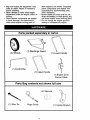
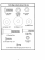
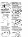
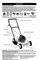
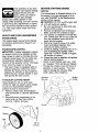
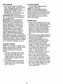
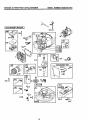
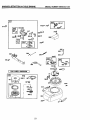
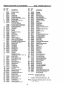
Owner's Manual
ROTARY LAWN MOWER
3.5 Horsepower
20" Side Discharge
Model Number
944.362010
CAUTION:
Read and follow all
Safety Rules and Instructions
before operating this equipment
Sears Canada,
Inc., Toronto, Ontario
M5B 2B8
Warranty .................................................
2
Safety Rules ........................................
2-4
Assembly / Pre-Operation
................... 6-7
Operation ...........................................
8-10
Maintenance
Schedule ........................
11
Maintenance ....................................
11-14
Product Specifications ..........................
12
Service and Adjustments ...................... 14
Storage .................................................
15
Troubleshooting
..............................
16-17
Repair Parts .....................................
18-19
Sears Service ......................... Back Cover
LIMITED ONE (1) YEAR WARRANTY ON COMPANION POWER MOWER
For one (1) year from date of purchase Sears Canada, Inc. will repair or replace at
Sears option free of charge parts which are defective as a result of material or workmanship.
COMMERCIAL OR RENTAL USE:
Warranty on Power Mower (Gas) will be ninety (90) days from date of purchase if used
for commercial or rental purposes.
This Warranty does NOT cover:
1. Pre-delivery set-up.
2. Expendable items which become worn during normal use, such as rotary mower
blades, blade adapters, belts, filters and spark plugs.
3. Repairs necessary because of operator abuse or negligence, including bent
crankshafts and the failure to operate and maintain the equipment according to the
instructions contained in the Owner's Manual.
Warranty service is available by returning the Companion Power Mower to the nearest
Sears Service Centre/Department in Canada. This warranty applies only while this
product is used in Canada.
This warranty is in addition to any statutory warranty and does not exclude or limit legal
rights you may have but shall run concurrently with applicable provincial legislation.
Furthermore, some provinces do NOT allow limitation on how long an implied warranty
will last so the above limitations may not apply to you.
SEARS CANADA, INC., TORONTO, ONTARIO M5B 2B8
IMPORTANT:
This cutting machine is capable of amputating hands and feet and
throwing objects. Failure to observe the following safety instructions could result in
serious injury or death.
I=
_,Look for this symbol to point out
important safety precautions. It means
CAUTION!!!
BECOMEALERTH!
YOUR
SAFETY IS INVOLVED.
_, CAUTION:
Always disconnect spark
plug wire and place wire where it cannot
contact spark plug in order to prevent
accidental starting when setting up,
transporting, adjusting or making repairs.
CAUTION:
Muffler and other engine
parts become extremely hot during
operation and remain hot after engine
has stopped. To avoid severe burns on
contact, stay away from these areas.
•
•
•
•
2
GENERAL
OPERATION
Read, understand, and follow all
instructions on the machine and in the
manual(s) before starting. Be thoroughly familiar with the controls and
the proper use of the machine before
starting.
Do not put hands or feet near or under
rotating parts. Keep clear of the
discharge opening at all times.
Only allow responsible individuals,
who are familiar with the instructions, to
operate the machine.
Clear the area of objects such as
rocks, toys, wire, bones, sticks, etc.,
which could be picked up and thrown
by the blade.
Be sure the area is clear of other
people before mowing. Stop machine if
anyone enters the area.
DO NOT:
• Do not operate the mower when
barefoot or wearing open sandals.
Always wear substantial foot wear.
• Do not pull mower backwards unless
absolutely necessary. Always look
down and behind before and while
moving backwards.
• Do not operate the mower without
proper guards, plates, grass catcher or
other safety protective devices in place.
• See manufacturer's
instructions for
proper operation and installation of
accessories. Only use accessories
approved by the manufacturer.
• Stop the blade(s) when crossing gravel
drives, walks, or roads.
, Stop the engine (motor) whenever you
leave the equipment, before cleaning
the mower or unclogging the chute.
• Shut the engine (motor) off and wait
until the blade comes to complete stop
before removing grass catcher.
• Mow only in daylight or good artificial
light.
, Do not operate the machine while
under the influence of alcohol or drugs.
o Never operate machine in wet grass.
Always be sure of your footing: keep a
firm hold on the handle and walk; never
run.
• Disengage the self-propelled
mechanism or drive clutch on mowers so
equipped before starting the engine
(motor).
, If the equipment should start to vibrate
abnormally, stop the engine (motor)
and check immediately for the cause.
Vibration is generally a warning of
trouble.
• Always wear safety goggles or safety
glasses with side shields when operating mower.
• Do not trim near drop-offs, ditches or
embankments. The operator could lose
footing or balance.
• Do not trim excessively steep slopes.
• Do not mow on wet grass. Reduced
footing could cause slipping.
IlL CHILDREN
Tragic accidents can occur if the operator
is not alert to the presence of children.
Children are often attracted to the
machine and the mowing activity. Never
assume that children will remain where
you last saw them.
• Keep children out of the trimming area
and under the watchful care of another
responsible adult.
• Be alert and turn machine off if children
enter the area.
• Before and while walking backwards,
look behind and down for small
children.
• Never allow children to operate the
machine.
• Use extra care when approaching blind
corners, shrubs, trees, or other objects
that may obscure vision.
IV. SERVICE
• Use extra care in handling gasoline
and other fuels. They are flammable
and vapors are explosive.
-Use only an approved container.
- Never remove gas cap or add fuel
with the engine running. Allow
engine to cool before refueling. Do
not smoke.
-Never refuel the machine indoors.
- Never store the machine or fuel
container inside where there is an
open flame, such as a water heater.
• Never run a machine inside a closed
area.
Never make adjustments or repairs with
the engine (motor) running. Disconnect
the spark plug wire, and keep the wire
away from the plug to prevent accidental starting.
Keep nuts and bolts, especially blade
attachment bolts, tight and keep
equipment in good condition.
Never tamper with safety devices.
Check their proper operation regularly.
Keep machine free of grass, leaves, or
other debris build-up. Clean oil or fuel
spillage. Allow machine to cool before
storing.
U. SLOPE OPERATION
Slopes are a major factor related to slip
and fall accidents which can result in
severe injury. All slopes require extra
caution. If you feel uneasy on a slope, do
not mow it.
• Mow across the face of slopes: never
up and down. Exercise extreme caution
when changing direction on slopes.
• Remove obstacles such as rocks, tree
limbs, etc.
• Watch for holes, ruts, or bumps. Tall
grass can hide obstacles.
R
• Stop and inspect the equipment if you
strike an object. Repair, if necessary,
before restarting.
• Never attempt to make wheel height
adjustments while the engine (motor) is
running.
• Grass catcher components are subject
to wear, damage, and deterioration,
which could expose moving parts or
allow objects to be thrown. Frequently
check components and replace with
manufacturer's
recommended
parts,
when necessary.
• Mower blades are sharp and can cut.
Wrap the blade(s) or wear gloves, and
use extra caution when servicing them.
• Do not change the engine governor
setting or overspeed the engine.
Parts packed separately in carton
(4) Wheels
(1) Discharge Guard
(1) Lower Handle
(1) Control Bar
(1) Upper Handle
(1) Engine Zone
Control Cable
Parts Bag contents not shown full size
(4) Spacers
(1) Wire Tie
Rope Guide
(1) Upstop Bracket
4
Parts Bag contents shown full size
@
(4) Flange
Locknuts
3/8-16
(4) Hex Bolts
3/8-16 x 1
(4) Locknuts
3/8 -16
(2) Washers 3/4"
(4) Washers
7/8"
(2) Washers 1-1/4"
(2) Hex Bolts
1/4-20 x 1-1/2
(4) Shoulder Bolts
(2) Hex Bolts1/4-20
©
(5) Locknuts
1/4-20
x 3/4
(1) Hex Washer Head Self-tapping
R
Screw #10-24 x 1/2
_CAUTION:
Do not operate this mower
without the discharge guard or an entire
approved grass catcher in place. These
guards are for your protection and are
required by the American National
Standards Institute and Consumer
Products Safety Commission.
ACAUTION:
Disconnect spark plug wire
from spark plug and place wire where it
cannot come in contact with plug.
Read these instructions and this manual
in its entirety before you attempt to
assemble or operate your new lawn
mower.
IMPORTANT:
This lawn mower is
shipped WITHOUT OIL OR GASOLINE in
the engine.
Your new lawn mower has been assembled at the factory with the exception
of those parts left unassembled for
shipping purposes. All parts such as nuts,
washers, bolts, etc., necessary to complete the assembly have been placed in
the parts bag. To ensure safe and proper
operation of your lawn mower, all parts
and hardware you assemble must be
tightened securely. Use the correct tools
as necessary to ensure proper tightness.
TOOLS REQUIRED FOR ASSEMBLY
A socket wrench set will make assembly
easier. Standard wrench sizes are listed.
(1) 5/16" Wrench (1) Adjustable Wrench
(1) 7/16" Wrench (1) 9/16" Wrench
(1) 1/2" Wrench
(1) 3/4" Wrench
When right hand or left hand is mentioned in this manual, it means when you
are standing in the operating position,
behind the handle.
UNPACKCARTON
1. Remove all loose parts from carton.
2. Examine all items. Compare with list
of unassembled parts and hardware.
3. Remove lawn mower housing with
care. Avoid touching blade under
housing. Always wear gloves or other
protection when working under or
lifting mower.
ASSEMBLE LOWER HANDLE
3/4 hex bolts, flat washers, and
Iocknuts. Tighten securely.
3. Repeat for opposite side of mower.
Flat washers
Locknuts
Hex
bolts
ASSEMBLE
UPPER
HANDLE
1. Position upper handle over lower
handle with small hole for mounting
up-stop bracket to right side and
assemble 1/4-20 x 1-1/2 hex bolts and
1/4-20 Iocknuts. Tighten securely.
ASSEMBLE UPSTOP BRACKET
2. Position upstop bracket on the right
inside of upper handle as shown.
3. Install the hex washer head screw into
the hole in up-stop bracket and upper
handle. Tighten securely.
AS VIEWED
FROM FRONT OF MOWER
Up-stop
bracket-
Hex
washer
head
screw
\
- \
\ /- -_',
\
Lockouts
ASSEMBLE
WHEELS
Cutting height is determined by assembling the wheels in one of four possible
positions on the mower housing. All
wheels must be in the same height
position for even cutting.
NOTE: For ease of lower handle assem1. For each wheel, assemble shoulder
bly, raise rear of deck and block securely.
bolt and spacer as shown
1. Position lower handle on deck so cut2. Assemble 1-1/4" diameter washer
off flat is forward as shown.
(rear wheels only) and 3/8-16 Iocknut
2. Align holes in handle with holes in
on inside of mower housing and
tighten securely.
deck as shown and assemble 3/8-16 x 6
ASSEMBLE ENGINE ZONE CONTROL
CABLE TO ENGINE
Cable attaches under brake arm cover,
(opposite side of engine as spark plug).
1. Straighten cable and find the end with
the small plastic fitting.
2. Hook "Z" bend fitting on inner wire of
cable into hole in brake arm of engine.
3. Align tapered end of small plastic
fitting with hole in mounting bracket
and push until fitting snaps into place.
1-1/4"
(rear wheel only)
Mower housing
Shoulder
bolt
Wheel
ASSEMBLE
DISCHARGE
3/8-16
Locknut
bracket
GUARD
1. Place discharge guard on top of lawn
mower discharge opening.
2. Install two (2) 1/4-20 x 3/4 hex bolts
through housing and discharge guard,
3. Install two (2) 3/4" diameter washers
and two (2) 1/4-20 Iocknuts. Tighten
securely.
Small plastic
fitting
Locknut.=
Brake
arm
ASSEMBLE ENGINE ZONE CONTROL
CABLE TO UPPER HANDLE
Washers
Attach cable opposite upstop bracket.
1. Route cable below crossbar of lower
handle and up to control bar.
2. Hook "Z" bend fitting on inner wire into
hole in control bar.
3. Attach cable fitting to upper handle.
4. Secure cable to lower handle with
wire tie.
bar
Upper
Discharge
Up-stop
bracket
guard
zone
control
cable
Hex
INSTALL CONTROL BAR
1. Position control bar so flattened
section with hole is on opposite side
of handle as up-stop bracket.
2. Insert one end of control bar into
handle hole on inside of handle.
Carefully push in on opposite end of
control bar and insert into hole on
opposite side of handle.
INSTALL STARTER
1. Put threaded end of rope guide
through hole in side of upper handle
above lower handle crossbar. Secure
with 1/4-20 Iocknut.
2. Hold control bar against upper handle
and slowly pull engine starter rope out
until it will slip into loop of rope guide.
Upper
Rope
,p bracket
ROPE
7
Engine
starter rope
KNOW YOUR LAWN MOWER
READ THIS OWNER'S MANUALAND ALL SAFETY RULES BEFORE OPERATING YOUR
LAWN MOWER. Compare the iliustralJons with your lawn mower to familiarize yourself with
the location of various controlsand adjustments. Save this manual for future reference.
These symbols may appear on your lawn mower or in literature supplied with the
product. Learn and understand
there meaning.
CAUTION
ENGINE
OR WARNING
ON
ENGINE
OFF
FAST
SLOW
CHOKE
_perator
FUEL
presence
OIL
DANGER, KEEP HANDS
AND FEET AWAY
control bar
Starter handle
Engine oil cap with dipstick
Gasoline filler cap_
Discharge
guard
Primer
IMPORTANT: This lawn mower is shipped WITHOUT OIL OR GASOLINE in the engine.
MEETS CPSC SAFETY REQUIREMENTS
Sears rotary walk-behind power lawn mowers conform to the safety standards of the American
National Standards Institute and the U,S. Consumer Product Safety Commission. The blade
tums when the engine is running.
Operator presence control bar - must be
held down to the handle to start the engine.
Release to stop the engine.
Starter handle - used for starting the engine.
Primer - pumps additional fuel from the
carburetor to the cylinder for use when
starting a cold engine.
8
The operation of any lawn
mower can result in foreign
objects thrown into the
eyes, which can result in
severe eye damage.
Always wear safety glasses or eye
shields while operating your lawn mower
or performing any adjustments or repairs.
We recommend standard safety glasses
or a wide vision safety mask worn over
spectacles.
HOW TO USE YOUR LAWN MOWER
ENGINE SPEED
The engine speed was set at the factory
for optimum performance. Speed is not
adjustable.
ENGINE
ZONE
ACAUTION:
CONTROL
Federal
regulations
require
an engine control to be installed
lawn mower in order to minimize
on this
the risk
of blade contact injury. Do not under any
circumstances
attempt to defeat the
function of the operator control. The blade
turns when the engine is running.
• Your lawn mower is equipped with an
operator presence control bar which
requires the operator to be positioned
behind the lawn mower handle to start
and operate
TO ADJUST
the lawn
CUTTING
BEFORE STARTING
ENGINE
ADD OIL
Your lawnmower is shipped without oil in
the engine. For type and grade of oil to
use, see "ENGINE" in the Maintenance
section of this manual.
A CAUTION: DO NOT overfill engine with
oil, or it will smoke on startup.
1. Be sure lawnmower is level and area
around oil fill is clean.
2. Remove oil dipstick from oil fill spout.
Make sure that rim of spout is clean.
3. You receive a container of oil with the
unit. Slowly pour 3/4 (15 oz.) of the oil
from the container down the oil fill
spout into the engine.
4. Wait one minute to allow oil to settle.
Insert and tighten dipstick, then
remove it to check oil level.
5. Continue adding small amounts of oil
and rechecking the dipstick until it
reads full. DO NOT overfill, or engine
will smoke on startup.
6. Always be sure to retighten oil dipstick
before starting engine.
• Check oil level before each use. Add
oil if needed. Fill to full line on dipstick.
• Change the oil after every 25 hours of
operation or each season. You may
need to change the oil more often
under dusty, dirty conditions.
mower.
Gasoline
filler cap
HEIGHT
Raise wheels for low cut and lower
wheels for high cut, adjust cutting height
to suit your requirements. Medium
position is best for most lawns.
1. Remove wheel, bolt, and hardware
and reassemble in desired adjustment
hole.
2. Reinstall wheel components in the
same order as they were before
removal. Tighten securely.
Primer
3/8-16
Locknut
Engine
cap
ADD GASOLINE
TO STOP ENGINE
• Fill fuel tank to bottom of tank filler
neck. Do not overfill. Use fresh, clean,
regular unleaded gasoline with a
minimum of 87 octane. Do not mix oil
with gasoline. Purchase fuel in
quantities that can be used within 30
Adays to assure fuel freshness.
CAUTION: Wipe off any spilled oil or
fuel. Do not store, spill or use gasoline
near an open flame.
A CAUTION: Alcohol blended fuels
(called gasohol or using ethanol or
methanol) can attract moisture which
leads to separation and formation of
acids during storage. Acidic gas can
damage the fuel system of an engine
while in storage. To avoid engine
problems, the fuel system should be
emptied before storage of 30 days or
longer. Drain the gas tank, start the
engine and let it run until the fuel lines
and carburetor are empty. Use fresh fuel
next season. See Storage Instructions for
additional information. Never use engine
or carburetor cleaner products in the fuel
tank or permanent damage may occur.
• To stop engine, release operator
presence control bar.
NOTE: In cooler weather it may be
necessary to repeat priming steps. In
warmer weather over priming may cause
flooding and engine will not start. If you
do flood engine, wait a few minutes
before attempting to start and do not
repeat priming steps.
TO START ENGINE
NOTE: Due to protective coatings on the
engine, a small amount of smoke may be
present during the initial use of the
product and should be considered
normal.
1. To start a cold engine, push primer
three (3) times before trying to start.
Use a firm push. This step is not
usually necessary when starting an
engine which has already run for a
few minutes.
2. Hold operator presence control bar
down to the handle and pull starter
handle quickly. Do not allow starter
rope to snap back.
MOWING TIPS
• Under certain conditions, such as very
tall grass, it may be necessary to raise
the height of cut to reduce pushing
effort and to keep from overloading the
engine and leaving clumps of grass
clippings. It may also be necessary to
reduce ground speed and/or run the
lawn mower over the area a second
time.
• For extremely heavy cutting, reduce the
width of cut by overlapping previously
cut path and mow slowly.
• For better grass bagging and most
cutting conditions, the engine speed
should be set in the FAST position.
• For side discharge lawn" mowers,
cutting in a counter-clockwise
direction,
starting at the outside of the area to be
cut, spreads grass clippings more
evenly and puts less load on the
engine. To keep clippings off of
walkways, flower beds, etc., make the
first cuts in a clockwise direction.
• Pores in cloth grass catchers can
become filled with dirt and dust with
use and catchers will collect less grass.
To prevent this, regularly hose catcher
off with water and let dry before using.
• Keep top of engine around starter clear
and clean of grass clippings and chaff.
This will help engine air flow and
extend engine life.
10
.A,NTENANOESC.EDULE
AS YOU COMPLETE
REGULAR
f__
SERVICE
Check for Loose Fasteners
Clean/Inspect Grass Catcher
M
O
W
E
R
, (If Equipped)
Clean Lawn Mower
Clean Under Drive Cover
(Power-Propelled Mowers)
t/
I1_
_
¥#
Check drive belt/pulleys
IP°wer-Pr°pelled
Mowers)
Check/Sharpen/Replace
Lubrication Chart
Clean Battery/Recharge
IElectric Start Mowers I
E
_()_r_._C-Z SERVICE DATES
Ikf
I_
Blade
Check Engine Oil Level
Change Engine Oil
N
G ! Clean
I_
1_4
_
2
Clean or Replace Spark Plug
E Replace
AirFilterPaperCartridge
123 4 -
I_
1_1'1,2
Air Filter
Inspect Muffler
a
_3
Change
Service
Replace
Charge
V'2
more often when operating under a heavy load or in high ambient temperatures.
more often when operating in dirty or dusty conditions,
blades more often when mowing in sandy soil.
48 hours at end of season.
GENERAL RECOMMENDATIONS
LUBRICATION
The warranty on this lawn mower does
not cover items that have been subjected
to operator abuse or negligence. To
receive full value from the warranty,
operator must maintain mower as
instructed in this manual.
Some adjustments will need to be made
periodically to properly maintain your
unit.
All adjustments in the Service and
Adjustments section of this manual
should be checked at least once each
season.
• Once a year, replace the spark plug,
clean or replace air filter element and
check blade for wear. A new spark
plug and clean/new air filter element
assure proper air-fuel mixture and help
your engine run better and last longer.
• Follow the maintenance schedule in
this manual.
CHART
Wheel
adjuster (on
each wheel)
ine oil
Discharge
guard hinge pin
(_
Handle bracket mounting pins
(_) Spray lubricant
(_) See "ENGINE"
in Maintenance
section.
BEFOREEACHUSE
1. Check engine oil level.
2. Check for loose fasteners.
LUBRICATION
Keep unit well lubricated
CATION CHART").
(See
"LUBRI-
11
IMPORTANT:
Do not oil or grease
plastic wheel bearings. Viscous
lubricants will attract dust and dirt that
will shorten the life of the self-lubricating bearings. If you feel they must be
lubricated, use only a dry, powdered
graphite type lubricant sparingly.
PRODUCT
SPECIFICATIONS
Serial Number:
Date of Purchase:
Gasoline Capacity
/ Type:
1.0 Quarts (unleaded regular)
Oil Type (API-SF-SJ):
SAE 30 (above 32°F); SAE 5W-30 (below 32°F)
Oil Capacity:
20 Ounces
Spark Plug (Gap: .030")
Champion
Blade Bolt Torque:
35-40 ft. Ibs.
RJ19LM
• The model and serial numbers will be found on a decal on the rear of the mower
housing. Record both serial number and date of purchase in space provided above
LAWN MOWER
Always observe safety rules when
performing any maintenance.
TIRES
• Keep tires free of gasoline, oil, or insect
control chemicals which can harm
rubber.
• Avoid stumps, stones, deep ruts, sharp
objects and other hazards that may
cause tire damage.
BLADE CARE
For best results, mower blade must be
kept sharp. Replace bent or damaged
blades.
TO REMOVE BLADE
1. Disconnect spark plug wire from spark
plug and place wire where it cannot
come in contact with spark plug.
2. Turn lawn mower on its side. Make
sure air filter and carburetor are up.
3. Use a wood block between blade and
mower housing to prevent blade from
turning when removing blade bolt.
NOTE; Protect your hands with gloves
and/or wrap blade with heavy cloth.
4. Remove blade bolt by turning counterclockwise.
5. Remove blade and attaching hardware (bolt, lock washer and hardened
washer).
NOTE: Remove the blade adapter and
check the key inside hub of blade
adapter. The key must be in good
condition to work properly. Replace
adapter if damaged.
TO REPLACE BLADE
1. Position the blade adapter on the
engine crankshaft. Be sure key in
adapter and crankshaft keyway are
aligned.
2. Position blade on the blade adapter
aligning the two (2) holes in the blade
with the raised lugs on the adapter.
3. Be sure the trailing edge of blade
(opposite sharp edge) is up toward
the engine.
4. Install the blade bolt with the lock
washer and hardened washer into
blade adapter and crankshaft.
5. Use block of wood between blade and
lawn mower housing and tighten the
blade bolt, turning clockwise.
• The recommended tightening torque is
35-40 ft. Ibs.
IMPORTANT:
Blade bolt is grade 8 heat
treated.
TO SHARPEN BLADE
NOTE: We do not recommend
sharpening blade - but if you do, be sure
the blade is balanced.
Care should be taken to keep the blade
balanced. An unbalanced blade will
cause eventual damage to lawn mower
or engine.
• The blade can be sharpened with a file
or on a grinding wheel. Do not attempt
to sharpen while on the mower.
• To check blade balance, drive a nail
into a beam or wall. Leave about one
inch of the straight nail exposed. Place
center hole of blade over the head of
the nail. If blade is balanced, it should
remain in a horizontal position. If either
end of the blade moves downward,
sharpen the heavy end until the blade
is balanced.
Crankshaft
Blade ada
t keyway
Lockwasher
Blade
Blade
bolt
Hardened
12
washer
3rank
shaft
Trailing edge
Blade adapter
GRASS CATCHER
(if purchased as an accessory)
• The grass catcher may be hosed with
water, but must be dry when used.
• Check your grass catcher often for
damage or deterioration. Through
normal use it will wear. If catcher
needs replacing, replace only with a
manufacturer approved replacement
catcher. Give the lawn mower model
number when ordering.
ENGINE
_
LUBRICATION
Use only high quality detergent oil rated
with API service classification SF-SJ.
Select the oil's SAE viscosity grade
according to your expected operating
temperature.
SAE VISCOSITY GRADES
6O
8O
EFORE NEXT OIL CHANGE
NOTE: Although multi-viscosity oils
(5W30, 10W30 etc.) improve starting in
cold weather, these multi-viscosity oils
will result in increased oil consumption
when used above 32°F. Check your
engine oil level more frequently to avoid
possible engine damage from running
low on oil.
Change the oil after every 25 hours of
operation or at least once a year if the
lawn mower is not used for 25 hours in
one year.
Check the crankcase oil level before
starting the engine and after each five (5)
hours of continuous use. Tighten oil plug
securely each time you check the oil
level.
TO CHANGE
Drain plug
AIR FILTER
Your engine will not run properly and may
be damaged by using a dirty air filter.
Clean the element after every 25 hours of
operation or every season. Replace the
air filter every 100 hours of operation or
every season, whichever occurs first.
Service air cleaner more often under
dusty conditions.
TO CLEAN AIR FILTER ELEMENT
1. Remove screw.
2. Remove air cleaner carefully to
prevent dirt from entering carburetor.
3. Take air cleaner apart and clean air
filter element.
4. Wash filter element in liquid detergent
and water.
5. Wrap filter element in cloth and
squeeze dry.
6. Lightly coat filter element with clean
engine oil. Squeeze in towel to
remove excess oil. Do not saturate.
7. Reassemble parts and put back on
carburetor.
ENGINE OIL
1. Disconnect spark plug wire from spark
plug and place wire where it cannot
come in contact with spark plug.
2. Be sure lawn mower is on level
surface.
NOTE: Oil will drain more freely when
warm. Catch oil in a suitable container.
3. Remove bottom oil drain plug.
4. After oil has drained completely,
replace oil drain plug and tighten
securely.
5. Fill engine with oil. (See "ADD OIL" in
the Operation section of this manual).
6. Reconnect spark plug wire to spark
plug.
ASSEMBLE SO LIP
EXTENDS OVER
EDGEOF
AIR CLEANER
BODY
LIP WILL FORM
PROTECTIVE
SEALWHEN
COVER IS ASSEMBLED
13
MUFFLER
Inspect and replace corroded muffler as it
could create a fire hazard and/or damage.
SPARK PLUG
Replace spark plugs at the beginning of
each mowing season or after every 100
hours of operation, whichever occurs first.
Spark plug type and gap setting are
shown in "PRODUCT SPECIFICATIONS"
in Maintenance section of this manual.
CLEANING
IMPORTANT:
For best performance,
keep mower housing free of built-up
grass and trash. Clean the underside of
your mower after each use.
_I,CAUTION:
Disconnect spark plug wire
from spark plug and place wire where it
cannot come in contact with the spark
plug.
• Clean the underside of your lawn
mower by scraping to remove build-up
of grass and trash.
• Clean engine often to keep trash from
accumulating. A clogged engine runs
hotter and shortens engine life.
• Keep finished surfaces and wheels free
of all gasoline, oil, etc.
• We do not recommend using a garden
hose to clean lawn mower unless the
electrical system, muffler, air filter and
carburetor are covered to keep water
out. Water in engine can result in
shortened engine life.
ENGINE
AWARNING:
To avoid serious injury,
before performing any service or adjustments:
1. Release control bar and stop engine.
2. Make sure the blade and all moving
parts have completely stopped.
3. Disconnect spark plug wire from spark
plug and place where it cannot come
in contact with plug.
ENGINE SPEED
Your engine speed has been factory set.
Do not attempt to increase engine speed
or it may result in personal injury. If you
believe that the engine is running too fast
or too slow, take your lawn mower to a
Sears or other qualified service center for
repair and adjustment.
LAWN MOWER
CARBURETOR
TO ADJUST CUTTING HEIGHT
See "TO ADJUST CUTTING HEIGHT" in
the Operation section of this manual.
Your carburetor is not adjustable. If your
engine does not operate properly due to
suspected carburetor problems, take your
lawn mower to a Sears or other qualified
service center for repair and/or adjustment.
IMPORTANT:
Never tamper with the
engine governor, which is factory set for
proper engine speed. Overspeeding the
engine above the factory high speed
setting can be dangerous. If you think the
engine-governed high speed needs
adjusting, contact a Sears or other
qualified service center, which has proper
equipment and experience to make any
necessary adjustments.
REAR DEFLECTOR
The rear deflector, attached between the
rear wheels of your mower, is provided to
minimize the possibility that objects will
be thrown out of the rear of the mower
into the operator's mowing position. If the
deflector becomes damaged, it should be
replaced.
DISCHARGE
GUARD
The discharge guard, attached to the
discharge opening of your lawn mower, is
provided to prevent the possibility of
injury resulting from objects being thrown
out of the discharge opening into the
operator mowing position. If the discharge
guard becomes damaged, it should be
replaced.
14
Immediately prepare your lawn mower for
storage at the end of the season or if the
unit will not be used for 30 days or more.
LAWN MOWER
When lawn mower is to be stored for a
period of time, clean it thoroughly, remove
all dirt, grease, leaves, etc. Store in a
clean, dry area.
1. Clean entire lawn mower (See
"CLEANING" in the Maintenance
section of this manual).
2. Lubricate as shown in the Maintenance section of this manual.
3. Be sure that all nuts, bolts, screws,
and pins are securely fastened.
Inspect moving parts for damage,
breakage and wear. Replace if
necessary.
4. Touch up all rusted or chipped paint
surfaces; sand lightly before painting.
ENGINE
FUELSYSTEM
IMPORTANT:
It is important to prevent
gum deposits from forming in essential
fuel system parts such as carburetor, fuel
filter, fuel hose, or tank during storage.
Also, alcohol blended fuels (called
gasohol or using ethanol or methanol)
can attract moisture which leads to
separation and formation of acids during
storage. Acidic gas can damage the fuel
system of an engine while in storage.
1. Drain the fuel tank,
2. Start the engine and let it run until the
fuel lines and carburetor are empty.
• Never use engine or carburetor cleaner
products in the fuel tank or permanent
damage may occur.
• Use fresh fuel next season.
NOTE: Fuel stabilizer is an acceptable
alternative in minimizing the formation of
fuel gum deposits during storage. Add
stabilizer to gasoline in fuel tank or
storage container. Always follow the mix
ratio found on stabilizer container, Run
engine at least 10 minutes after adding
stabilizer to allow the stabilizer to reach
the carburetor. Do not drain the gas tank
and carburetor if using fuel stabilizer.
ENGINE OIL
Drain oil (with engine warm) and replace
with clean engine oil. (See "ENGINE" in
the Maintenance section of this manual).
CYLINDER
1. Remove spark plug.
2. Pour one ounce (29 ml) of oil through
spark plug hole into cylinder.
3. Pull starter handle slowly a few times
to distribute oil.
4. Replace with new spark plug.
OTHER
• Do not store gasoline from one season
to another.
• Replace your gasoline can if your can
starts to rust. Rust and/or dirt in your
gasoline will cause problems.
• If possible, store your unit indoors and
cover it to protect it from dust and dirt.
• Cover your unit with a suitable protective cover that does not retain moisture.
Do not use plastic. Plastic cannot
breathe, which allows condensation to
form and will cause your unit to rust.
IMPORTANT: Never cover mower while
engine and exhaust areas are still warm.
A CAUTION: Never store the lawn mower
with gasoline in the tank inside a building
where fumes may reach an open flame or
spark. Allow the engine to cool before
storing in any enclosure.
1R
TROUBLESHOOTING
- See appropriate
to a Sears Service Center.
PROBLEM
Does not start
section in manual unless directed
CAUSE
CORRECTION
1, Dirty air filter.
1. Clean/replace air filter.
2. Out of fuel.
3. Stale fuel.
2. Fill fuel tank.
3. Drain tank and refill with
fresh, clean fuel.
4. Drain fuel tank and
carburetor and refill tank
with fresh gasoline.
5. Connect wire to plug.
4. Water in fuel.
5. Spark plug wire is
disconnected.
6. Bad spark plug.
7. Loose blade or broken
blade adapter.
8. Control bar in released
position.
9. Control bar defective.
10. Fuel valve lever (if so
equipped) in OFF position.
1R
6. Replace spark plug.
7. Tighten blade bolt or
replace blade adapter.
8. Depress control bar to
handle.
9. Replace control bar.
10.Turn fuel valve lever
to the ON position.
TROUBLESHOOTING - See appropriate section in manual unless directed
to a Sears Service Center.
CAUSE
PROBLEM
Loss of power
CORRECTION
1. Rear of housing or blade
dragging in heavy grass.
2. Cutting too much grass.
3. Dirty air filter.
4. Buildup of grass, leaves,
and trash under mower.
5. Too much oil in engine.
6. Walking speed too fast.
Poor cut uneven
1. Worn, bent or loose blade.
2. Wheel heights uneven.
3. Buildup of grass, leaves
and trash under mower.
Excessive
vibration
1. Worn, bent or loose blade.
2. Bent engine crankshaft.
Starter rope
hard to pull
Engine flywheel brake is
on when control bar is
released.
2. Bent engine crankshaft.
.
3. Blade adapter broken.
4. Blade dragging in grass.
1. Set to "Higher Cut" position.
2. Set to "Higher Cut"
position.
3. Clean/replace air filter.
4. Clean underside of mower
housing.
5. Check oil level.
6. Cut at slower walking
speed.
1. Replace blade. Tighten
blade bolt.
2. Set all wheels at same
height.
3. Clean underside of
mower housing.
1. Replace blade. Tighten
blade bolt.
2. Contact a Sears or other
qualified service center.
1. Depress control bar to
upper handle before
pulling starter rope.
2. Contact a Sears or other
qualified service center.
3. Replace blade adapter.
4. Move lawn mower to cut
grass or to hard surface.
Grass catcher
notfilUng(ifso
equipped)
1. Cutting height too low.
2. Lift on blade worn off.
3. Catcher not venting air.
1. Raise cutting height.
2. Replace blade.
3. Clean grass catcher.
Hard to push
1. Grass is too high or wheel
height is too low.
2. Rear of housing or blade
dragging in heavy grass.
3. Grass catcher too full.
4. Handle height position not
right for you.
1. Raise cutting height.
17
2. Raise rear of mower housing
one (1) setting higher.
3. Empty grass catcher.
4. Adjust handle height to
suit.
ROTARY LAWN MOWER -- MODEL NUMBER 944.362010
39
2O
\
21
14
22
11
12
22
24
24
33
f
35
2O
19
21 _
_
23
22
13
ROTARY LAWN MOWER - - MODEL NUMBER 944.362010
KEY PART
NO. NO.
(.D
1
2
3
86902
179585
750097
4
5
7
8
9
10
11
12
13
14
16
17
18
19
20
21
22
23
172146X479
63601
169711X479
163799
7435O424
86899X004
66426
137009
700839)(479
140541
87584X004
851201X004
53847
752052
67609
700263
136624
107339X
DESCRIPTION
Control Bar
RopeGuide
Screw, Hex Washer Head,
Self-tapping #10-24 x 1/2
LowerHandle
Hex Locknut 1/4-20
Upper Handle
Engine Zone Control Cable
Hex Head Screw 1/4-20 x 1-1/2
Up-Stop Bracket
WireTie
Hex Head Bolt 3/8-16 x 3/4
Front Baffle
Rear Skirt
Deflector Bracket
Engine Washer
Fiat Washer
Discharge Guard
Shoulder Bolt
Wheal Assembty
Wheel Spacer
Danger Decal
KEY
NO.
PART
NO.
24
26
27
28
29
30
31
33
34
35
36
37
38
39
55611
61537
132010
74760412
751592
150406
132004
181940
850977
850972
851074
850263
851084
- - -
40
41
--o-
128415
750634
162300
181937
181938
NOTE:
DESCRIPTION
Washer
Washer
Flange Locknut
Hex Head Screw 1/4
Hex Leaknut 3/8-16
Hex Head Thread Rolling Screw 3/8-16 x 1
Hex Nut 1/4-20
Housing
Blade Adapter
Blade 20"
Washer(Hardened)
Helical Lock Washer
Hex Head Machine Screw 3/8-24 x 1-3/8 Gr. 8
Engine, Bdggs & Stratton, Model Number
9E902-0214-B1 (See Breakdown)
Pop Rivets
Screw
Warning Decal (Not Shown)
Owner's Manual (English)
Owner's Manual (French)
All component dimensions
1 inch = 25.4 mm
given in U.S, inches.
BRIGGS & STRATTON
] 1058 OWNER'S
4-CYCLE
ENGINE
MODEL NUMBER 9E902-0214-B1
MANUAL I
524
_
I
524_
358 GASKET SET
83__
190_
190A_
670
BRIGGS
& STRATTON
4-CYCLE
ENGINE
MODEL
NUMBER
9E902-O214-B1
901
745A_
973
617
621
7451
s29_
393_ 39ol
612
365
772T
925
729 _3
615 °
209 J--
616
334_
188 _22_
I 851
332
455_
I
1036 LABEL-EMISSION
I
73(
65y
592 ®
469_
58_
6o_
23
1276
37A
689
1
._.m
3O4
3O5_
21
37
BRIGGS
& STRATTON
K_-Y
NO.
PART
NO.
1
2
3
4
5
7
8
9
10
11
12
697401
399269
299819
697412
690386
692288
495785
695890
691666
691245
692218
32
33
34
35
36
37
37A
40
45
46
43
48
270895
270896
691697
691680
691475
293709
391483
691662
692009
222698
498668
498680
691588
298909
298908
294201
296079
94699
296676
296677
690520
690520
691209
697403
692194
691762
691998
697799
- - -
50
51
54
55
58
60
65
73
90
97
130
163
180
188
190
190A
202
209
222
227
300
304
305
332
333
334
693446
270345
93485
692144
692259
691915
690837
691235
697800
697414
691190
271139
494406
94786
692198
691697
697407
697797
697796
697402
394569
697795
692198
690662
496914
690482
13
15
16
19
20
22
23
24
25
26
27
28
29
4-CYCLE
ENGINE
DESCRIPTION
°
•
•
•
•
°
°
Cylinder Assembly
Bushing
OilSeal
Engine Sump
Cylinder Head
Cylinder Head Gasket
Breather Assy (Includes Gasket)
Breather Gasket
Screw (Breather Assembly)
BreatherTube
Crankcase Gasket
(,015" Thick, Standard)
Crankcase Gasket (.005" Thick)
Crankcase Gasket (.009" Thick)
Screw (Cylinder Head)
C)il Drein Plug
Crankshaft
Bushing
OilSeal
Screw(Engine Sump)
Flywheel
Flywheel Key
Piston Assembly
Ring Set
Piston Pin Lock
Piston Pin (Standard)
Piston Pin (.005" Oversize)
Connecting Rod (Standard)
ConnectingRod(.020"Undersize)
Screw (Connecting Rod)
Exhaust Valve
Intake Valve
Valve Spdng
Valve Spring
FlywheeIGuard
FlywheelGuard
Valve Retainer
Valve Tappet
Cam Gear
Oil Slinger
Replacement Engine
10E902-0015-E1 (Short Block n/a)
Intake Manifold
Intake Gasket
Screw (intake Manifold)
Rewind Starter Housing
Starter Rope
Starter Rope Grip
Screw(Rewind Starter)
Rotating Screen
Carburetor
Throttle Shaft
Throttle Valve
AirCleanerGasket
FueITank
Screw (Control Bracket)
Screw(FueITank)
Screw(FuelTank)
Link-Mechanical Governor
Spdng-Govemor
Brecket-Contml
Governor Control Lever
Muffler (Lo Tone)
Blower Housing
Screw (Blower Housing)
Nut(Flywheel)
Armature-Magneto
Screw (Magneto Armature)
MODEL
K]EY PART
NO. NO.
337
356
358
363
365
383
390
393
394
404
455
456
459
469
505
523
524
529
534
535
536
562
570
592
597
608
612
616
617
621
633
635
670
689
718
724
729
741
745
745A
772
851
869
870
871
913
922
923
925
957
973
976
1036
1058
1210
1211
1276
802592
692390
298989
19069
692200
89838
6918,39
691837
495770
690272
691236
692299
281505
694420
691251
691913
691876
692189
691417
272235
493492
92613
691911
690800
691696
499706
496046
697405
270344
692310
691321
66538
6916,33
691855
499047
697478
690586
691805
691146
690859
691 t 11
493880
211172
211291
231348
63709
494409
692135
691487
691349
497929
694394
494408
695108
273690
499901
499901
691002
RPM Settings:
NUMBER
9E902-0214-B1
DESCRIPTION
Sparkplug
StopWire
Gasket Set
FlywheelPuller
Screw(Carburetor)
Spark PlugWrench
ChokeDiaphragmSpring
CarburetorScreen
CarburetorDiaphragm
Washer
FlywheelCup
SpringRetainer
RatchetPawl
RotatingTrimRing
Nut (GovernorControlLever)
Dipstick
O Ring Seal (DipstickTube)
Grommet
Screw(AirCleaner)
Air Filter
AirCleaner
Bolt(GovemorControlLever)
FoamElementSupport
Nut(RewindStarter)
Screw(RatchetPawl)
Rewind Startsr
Pickup Tube
GovernorCrenk
O Ring Seal (Intake Manifold)
Stop Switch
Choke/Throttle Shaft Seal
Spark PlugBoot
Spacer
FdctionSpring
LocatingPin
RetainerSeal
WireClip
TimingGear
Screw(Brake)
Screw (Brake)
Screw(Linkage Cover)
SparkPlugTerminal
Valve Seat (Intake)
Valve Seat (Exhaust)
Guide Bushing(Exhaust)
GuideBushing(Intake) •
Check Valve Seat
BrakeSpring
Brake Bracket
LinkageCover
FuelTank Cap (Plastic)
TrimRing(PdmerBulb)
CarburetorPrimer
EmissionLabel
Owner'sManual
Pulley/Spring Assembly (Pulley)
Pulley/Spring Assembly (Spring)
Screw (Governor Lever Nut
Mounting Guard)
Low Speed: 1900-2100
High Speed: 3000-3200
Included in Engine Gasket Set, Key No, 358
NOTE:
All component dimensions given in U.S. inches
1 inch = 25.4 mm
SERVICE
23
NOTES
Just Call:
1-800-4-MY-HOME ®
(1-800-469-4663)
24 hours a day, 7 days a week
For the repairof major brand appliances In your own home...
no matter who made it, no matter who sold it!
For your nearest Sears Parts and Service location,
to bring in productslike vacuums, lawn equipment and electronics.
For Sears Parts & Service, to order the replacementparts,
accessoriesand owner's manuals that you need to do-it-yourself.
www.sears.c8
To purchase or inquire about a Sears Maintenance Agreement, call:
1-800-361-6665
9 a.m. - 8 p.m. EST, Mort. - Fri,,4 p.m. Sat.
Pour service en franq,ais:
!
1-800-LE-FOYER Mc
(1-800-533-6937)
www.sears.ca
....
!iiii!i:iiii_iiii;
®/TM Trademarks of Sesrs, Roeb_x:k and Co. used under license by Sears Canada
_c I _ Marque de commerce / d_po_
de Seam, Roebuck and Ca. uti_lsdeen vedu d'une llce_,e de Seam Canada
181937 Rev. 1 03.07.02
BY
O Sears
Printed in U.S.A.