1
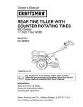
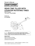
Owner's Manual
JCRIIFTSMIIN'I
TILLER
5.5 HP, 14 Inch Tine Width
Rear Tine with
Counter Rotating _nes
Model No.
917.293471
_]_..I-.J_
!_
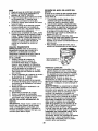
This product has a low emission engine which operates
differently from previously built engines. Before you start the en-
gine, read and understand this Owner's Manual.
CAUTION:
Read and follow all Safety
Rules and Instructions before
operating this equipment.
Sears, Roebuck and Co., Hoffman Estates, II 60179 U.S.A.
Visit our Craftsman
website:www.sears.com/craftsman
Safety Rules .........................................
Warranty ...............................................
Product Specifications ..........................
Assembly ..............................................
Operation ..............................................
Maintenance
Schedule ......................
Maintenance ....................................... 13
Service and Adjustments .................... 15
Storage ............................................... 19
Troubleshooting ................................. 20
Illustrated Parts List ............................ 42
Sears Service ...................... Back Cover
2
2
4
5
8
13
LIMITED ONE YEAR WARRANTY ON CRAFTSMAN TILLER
For one (1) year from date of purchase, when this Craftsman Tiller is maintained,
lubricated, and tuned up according to the operating and maintenance instructions in
the owner's manual, Sears will repair free of charge any defect in material or workmanship.
This Warranty does not cover:.
• Expendable items which become worn during normal use, such as tines, spark
plugs, air cleaners and belts.
• Repairs necessary because of operator abuse or negligence, including bent
crankshafts and the failure to maintain the equipment according to the instructions
contained in the owner's manual.
• If this Craftsman Tiller is used for commercial or rental purposes, this Warranty
applies for only thirty (30) days from the date of purchase.
Warranty service is available by returning the craftsman power mower to the nearest
sears service center/department in the united states. This warranty applies only while
this product is in use in the united states.
This Warranty gives you specific
vary from state to state.
SEARS,
ROEBUCK
legal rights, and you may also have other rights which
AND CO., D/817WA,
HOFFMAN
ESTATES,
IL 60179
IMPORTANT: This cutting machine is capable of amputating hands and feet and
throwing objects. Failure to observe the following safety instructions could result in
serious injury or death.
TRAINING
• Read the Owner's Manual carefully. Be
thoroughly familiar with the controls
and the proper use of the equipment.
Know how to stop the unit and disengage the controls quickly.
• Never allow children to operate the
equipment. Never allow adults to
operate the equipment without proper
instruction.
• Keep the area of operation clear of all
persons, particularly small children,
and pets.
PREPARATION
• Thoroughly inspect the area where the
equipment is to be used and remove all
foreign objects.
2
• Disengage all clutches and shift into
neutral before starting the engine
(motor).
• Do not operate the equipment without
wearing adequate outer garments.
Wear footwear that will improve footing
on slippery surfaces.
• Handle fuel with care; it is highly
flammable.
• Use an approved fuel container.
• Never add fuel to a running engine or
hot engine.
• Fill fuel tank outdoors with extreme
care. Never fill fuel tank indoors.
• Replace gasoline cap securely and
clean up spilled fuel before restarting.
• Use extension cords and receptacles
as specified by the manufacturer for all
units with electdc drive motors or
electric starting motors.
• Never attempt to make any adjustments
while the engine (motor) is running
(except where specifically recommended by manufacturer).
OPERATION
• Never operate the tiller without good
visibility or light.
• Be careful when tilling in hard ground.
The tines may catch in the ground and
propel the tiller forward. If this occurs,
let go of the handlebars and do not
restrain the machine.
• Do not put hands or feet near or under
rotating parts.
• Exercise extreme caution when
operating on or crossing gravel drives,
walks, or reads. Stay alert for hidden
hazards or traffic. Do not carry passengers.
• After striking a foreign object, stop the
engine (motor), remove the wire from
the spark plug, thoroughly inspect the
tiller for any damage, and repair the
damage before restarting and operating the tiller.
• Exercise caution to avoid slipping or
falling.
• If the unit should start to vibrate
abnormally, stop the engine (motor)
and check immediately for the cause.
Vibration is generally a warning of
trouble.
• Stop the engine (motor) when leaving
the operating position.
• Take all possible precautions when
leaving the machine unattended.
Disengage the tines, shift into neutral,
and stop the engine.
• Before cleaning, repairing, or inspecting, shut off the engine and make
certain all moving parts have stopped.
Disconnect the spark plug wire, and
keep the wire away from the plug to
prevent accidental starting. Disconnect
the cord on electric motors.
• Do not run the engine indoors; exhaust
fumes are dangerous.
• Never operate the tiller without proper
guards, plates, or other safety protective devices in place.
• Keep children and pets away.
• Do not overload the machine capacity
by attempting to till too deep at too fast
a rate.
• Never operate the machine at high
speeds on slippery surfaces. Look
behind and use care when backing.
• Never allow bystanders near the unit.
• Use only attachments and accessories
approved by the manufacturer of the
tiller.
MAINTENANCE
AND STORAGE
• Keep machine, attachments, and
accessories in safe working condition.
• Check shear pins, engine mounting
bolts, and other bolts at frequent
intervals for proper tightness to be sure
the equipment is in safe working
condition.
• Never store the machine with fuel in the
fuel tank inside a building where
ignition sources are present, such as
hot water and space heaters, clothes
dryers, and the like. Allow the engine to
cool before storing in any enclosure.
• Always refer to the operator's guide
instructions for important details if the
tiller is to be stored for an extended
period.
_Look for this symbol to point out
important safety precautions. It means
CAUTION!!!
BECOMEALERTH!
YOUR
SAFETY IS INVOLVED.
ACAUTION:
Always disconnect spark
plug wire and place wire where it cannot
contact spark plug in order to prevent
accidental starting when setting up,
transporting, adjusting or making repairs.
_,WARNING:
Engine exhaust, some of its
constituents, and certain vehicle components contain or emit chemicals known to
the State of California to cause cancer
and birth defects or other reproductive
harm.
3
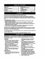
PRODUCT SPECIFICATIONS
GASOLINE
3 QUARTS
CAPACITY:
UNLEADED
REGULAR
OIL(API-SF-SJ):
SAE30
CAPACITY:20OZ.) (ABOVE32°F)
SAE5W-30
(BELOW32°F)
SPARKPLUG:
CHAMPION
(GAP: .030")
RC12YC
CUSTOMER
RESPONSIBILITIES
• Read and observe the safety rules.
• Follow a regular schedule in maintaining, caring for and using your tiller.
• Follow the instructions under the
=Customer Responsibilities" and
=Storage" sections of this Owner's
Manual.
_WARNING:
This unit is equipped with
an internal combustion engine and
should not be used on or near any
unimproved forest-covered, brushcovered or grass covered land unless the
engine's exhaust system is equipped with
a spark arrester meeting applicable local
or state laws (if any). If a spark arrester is
used, it should be maintained in effective
working order by the operator.
In the state of California the above is
required by law (Section 4442 of the
California Public Resources Code).
Other states may have similar laws.
Federal laws apply on federal lands. A
spark arrester for the muffler is available
through your nearest Sears service
center (See REPAIR PARTS section of
this manual).
CONGRATULATIONS on your purchase
of a Sears Tiller. It has been designed,
engineered and manufactured to give
you the best possible dependability and
performance.
Should you experience any problems you
cannot easily remedy, please contact a
Sears or other qualified Service Center.
We have competent, well-trained technicians and the proper tools to service or
repair this unit.
Please read and retain this manual. The
instructionswill enable you to assemble
and maintain your tiller properly. Always
observe the =SAFETY RULES".
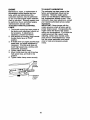
Your new tiller has been assembled at the
factory with exception of those parts left
unassembled for shipping purposes. To
ensure safe and proper operation of your
tiller all parts and hardware you assemble must be tightened securely. Use
the correct tools as necessary to insure
proper tightness.
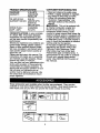
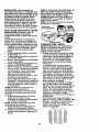
These accessories were available when the tiller was purchased. They are also
available at most Sears Retail outlets and Service Centers. Most Sears Stores can
order repair parts for you when you provide the model number of your tiller.
ENGINE
TILLER
TILLER
PERFORMANCE
MAINTENANCE
BELT
TINES
SHEAR
4
PIN
HAIRPIN
CLIP
Your new tiller has been assembled at the
factory with exception of those parts left
unassembled for shipping purposes. To
ensure safe and proper operation of your
tiller all parts and hardware you assemble
must be tightened securely. Use the
correct tools as necessary to insure
proper tightness.
TOOLS REQUIRED
FRONT
RIGHT
LEFT
FOR ASSEMBLY
A socket wrench set will make assembly
easier. Standard wrench sizes are listed,
(1) Utility knife
(1) Wire cutter
(1) Tire pressure gauge
(t) Screwdriver
(1) Pair of pliers
(1) 9/16" wrench
OPERATOR'S POSITION
OPERATOR'S
POSITION
When right or left hand is mentioned in
this manual, it means when you are in the
operating position (standing behind tiller
handles).
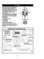
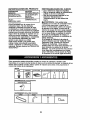
CONTENTS OF HARDWARE PACK
/lllllll/Y
(2) Handle Locks
/1) Carriage Bolt
8-16 UNC x 1 Gr. 5
(1) Center Locknut
3/8-16 UNC
(1) Cable Clip
(1) Hairpin Clips
(1) Pivot Bolt
3/8-16
UNC
, (1) FlatWasher
13/32
x 1 x 11 Ga.
©
(2) Shear
(1) Handle
Pins & Clips
5
Lock Lever
Grade
5
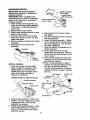
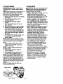
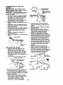
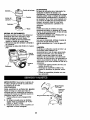
UNPACKINGCARTON
_CAUTION:
Be careful of exposed
staples when handling or disposing of
cartoning material.
IMPORTANT: When unpacking and
assembling tiller, be careful of exposed
staples when handling or disposing of
cartoning material.
1. While holding handle assembly, cut
cable ties securing handle assembly
to top frame. Let handle assembly
rest on tiller.
2. Remove top frame of carton.
3. Slowly ease handle assembly up and
place on top of carton.
4. Cut down dght hand front and right
hand rear comers of carton, lay side
carton wall down.
5. Remove packing matadal from handle
assembly.
6. Separate shift rod from handle
assembly.
::__
Handle Assembly
UP" Position
lever to hold
Loosen Handle Lock
Lever to Move
4.
Insert pivot bolt in front part of plate
and tighten.
5. Cut down remaining comers of carton
and lay panels flat.
6. Lower the handle assembly. Tighten
nut on carriage bolt so handle moves
with some resistance. This will allow
for easier adjustment.
7. Place flat washer on threaded end of
handle lock lever.
8. Insert handle lock lever through
handle base and gearcase. Screw in
handle lock lever just enough to hold
lever in place.
9. Insert second handle lock (with teeth
inward) in the slot of the handle base
(just inside of washer).
10.Raise
handle assembly to highest
position and securely tighten handle
lock lever by rotating clockwise.
Leaving handle assembly in highest
position will make it easier to connect
shift rod.
Shift Rod
Assembly
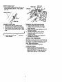
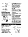
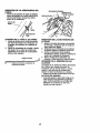
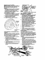
INSTALL
/
....
HANDLE
1. Insert one handle lock (with teeth
facing outward) in gearcase notch.
(Apply grease on smooth side of
handle lock to aid in keeping lock in
place until handle assembly is
lowered into position.)
Flat Washer
Handle Lock,
VIEWED FROM R.H. SIDE OF TILLER
Handle Lock
Lever
Gearcase_
Slot
Handle Assembly
arcase Notch
Handle Lock
Rear Cartridge
Locknut _
Handle Base
2. Grasp handle assembly. Hold in "up"
position. Be sure handle lock remains
in gearcase notch. Slide handle
assembly into position.
3. Rotate handle assembly down. Insert
rear carriage bolt first, with head of
bolt on L.H. side of tiller and loosely
assemble Iocknut.
6
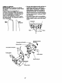
Pivot Bolt
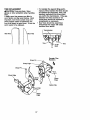
INSERT
CABLE
CLIP
Hairpin
• Insert plastic cable clip into hole on the
back of handle column. Push cables
into clip.
Shift Lever
Indicator
Shift Rod
Handle Column
Cables
Cable Clip
CONNECT SHIFT ROD
1. Insert end of shift rod farthest from
bend into hole of shift lever indicator.
2. Insert hairpin clip through hole of shift
rod to secure with bend of clip on right
side.
[_Attach
this End To shift _
REMOVE
TILLER
FROM
CRATE
1. Adjust handle assemby to lowest
position. Be sure lock lever is tightened securely.
2. Make sure shift lever indicator is in "N"
(neutral) position.
3. Tilt tiller forward by lifting handle.
Separate cardboard cover from
leveling shield.
4. Rotate tiller handle to the right and
pull tiller out of carton.
Shift Rod
Lever Indicator
CHECK TIRE PRESSURE
The tires on your unit were overinflated at
the factory for shipping purposes. Correct
and equal tire pressure is important for
best tilling performance.
• Reduce tire pressure to 20 PSI.
HANDLE HEIGHT
• Handle height may be adjusted to
better suit operator. (See "TO ADJUST
HANDLE HEIGHT" in the Service and
Adjustments section of this manual).
7
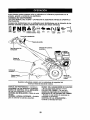
Thesesymbols may appearon yourTilleror in literaturesuppliedwith the product.
Learnand understandtheir meaning.
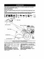
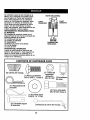
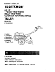
KNOW YOUR TILLER
READ THIS OWNER'S
TILLER.
MANUALAND
SAFETY
RULES
BEFORE
OPERATING
YOUR
Compare the illustrations
with your tiller to familiarize yourself with the location
various controls and adjustments,
Save this manual for future reference.
of
FNR&
Throttle Control
Shift Lever
Drive Control Bar
Shift Lever Indicator
Leveling
Recoil
Starter
Handle
Outer Side
MEETS ANSI SAFETY REQUIREMENTS
Our tillers conform to the safety standards of the American National Standards Institute.
DRIVE CONTROL
tines.
BAR - Used to engage
LEVELING SHIELD - Levels tilled soil.
SHIFT LEVER - Used to shift transmission
gears.
SHIFT LEVER INDICATOR
- Shows
which gear the transmission is in.
RECOIL STARTER HANDLE - Used to
start the engine.
DEPTH STAKE - Controls depth at which
tiller will dig.
OUTER SIDE SHIELD - Adjustable to
protect small plants from being buried.
THROI-rLE
CONTROL
- Used to control
engine speed.
8
The operation of any tiller can result in foreign objects thrown into the eyes,
which can result in severe eye damage. Always wear safety glasses or eye
shields before starting your tiller and while tilling. We recommend a wide
vision safety mask over spectacles or standard safety glasses.
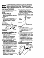
HOW TO USE YOUR TILLER
HARD TO SHIFT GEARS
• Briefly engage drive control bar and
release or rock tiller forward and
backward until are able to shift gears.
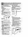
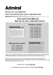
DEPTH STAKE
The depth stake can be raised or lowered
to allow you more versatile tilling and
cultivating, or to more easily transport
your tiller.
Know how to operate all controls before
adding fuel and oil or attempting to start
engine.
STOPPING
TINES AND DRIVE
1. Release drive control bar to stop
movement.
2. Move shift lever to =N" (neutral)
position.
ENGINE
Shallowest'nlling .....
(Cultivating)
• Move throttle control to =STOP" position. If equipped with stop switch, move
switch to =STOP" position.
NOTE: Never use choke to stop engine.
Drive Control Bar
"ENGAGED" Position
"" Transport Position
Deeptest "l]lling_
Depth Stake ------_
Shift Lever
J
TILLING
1. Release depth stake pin. Pull the
depth stake up for increased tilling
depth. Place depth stake pin in hole
of depth stake to lock in position.
2. Place shift lever indicator in till
position.
3. Hold the drive control bar against the
handle to start tilling movement. Tines
and wheels will both turn.
4. Move throttle control to =FAST"
position for deep tilling. To cultivate,
throttle control can be set at any
desired speed, depending on how fast
or slow you wish to cultivate.
IMPORTANT:
Always release drive
control bar before moving shift lever into
another position.
Drive Control Bar
"DISENGAGED"
Position
Throttle Control
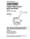
TINE OPERATION
DRIVE
- WITH
WHEEL
• Always release drive control bar before
moving shift lever into another position.
• Tine movement is achieved by moving
shift lever to (_) till position and
engaging drive control bar.
FORWARD - WHEELS ONLY/TINES
STOPPED
• Release drive control bar and move
Depth Stake Pin
=RELEASED" Position
shift lever indicator to =P' (forward)
position. Engage drive control bar and
tiller will move forward.
REVERSE - WHEELS ONLYrFINES
STOPPED
1. DO NOT STAND DIRECTLY BEHIND
TILLER.
2. Release the drive control bar.
3. Move throttle control to =SLOW"
position.
4. Move shift lever indicator to =R"
(reverse) position.
5. Hold drive control bar against the
handle to start tiller movement.
\
Nut
=B"
Side Shield
9
ULockedPosition
TURNING
1. Release the drive control bar.
2. Move throttle control to "SLOW"
position.
3. Place shift lever indicator in "F"
(forward) position. Tines will not turn.
4. Lift handle to raise tines out of ground.
5. Swing the handle in the opposite
direction you wish to turn, being
careful to keep feet and legs away
from tines.
• For approximate capacity see "PRODUCT SPECIFICATIONS" on page 4 of
this manual. All oil must meet A.P.I.
Service Classification SF-SJ.
• For cold weather operation you should
change oil for easier starting (See oil
viscosity chart in the Maintenance
section of this manual).
• To change engine oil, see the Maintenance section in this manual.
6. When you have completed your turnaround, release the drive control bar
and lower handle. Place shift lever in
(till) position and move throttle control
to desired speed. To begin tilling,
hold drive control bar against the
handle.
Oil Fill
TO TRANSPORT
_CAUTION:
Before lifting or transporting,
allow tiller engine and muffler to cool.
Disconnect spark plug wire. Drain
gasoline from fuel tank.
AROUND THE YARD
1. Release the depth stake pin. Move
the depth stake down to the top hole
for transporting the tiller. Place depth
stake pin in hole of depth stake to lock
in position. This prevents tines from
scuffing the ground.
2. Place shift lever indicator in =F"
3.
(forward) position for transporting.
Hold the drive control bar against the
handle to start tiller movement. Tines
will not turn.
4. Move throttle control to desired speed.
AROUND TOWN
1. Disconnect spark plug wire.
2. Drain fuel tank.
3. Transport in upright position to
prevent oil leakage.
BEFORE STARTING
ENGINE
IMPORTANT:
Be very careful not to allow
dirt to enter the engine when checking or
adding oil or fuel. Use clean oil and fuel
and store in approved, clean, covered
containers, use clean fill funnels.
CHECK ENGINE OIL LEVEL
The engine in your unit has been
shipped, from the factory, already filled
with SAE 30 summer weight oil.
1. With engine level, clean area around
oil filler plug and remove plug.
2. Engine oil should be to point of
overflowing when engine is level.
ADD GASOLINE
• Fill fuel tank. Use fresh, clean, regular
unleaded gasoline. (Use of leaded
gasoline will increase carbon and lead
oxide deposits and reduce valve life.)
IMPORTANT:
When operating in temperatures below 32°F(0°C), use fresh,
clean, winter grade gasoline to help
insure good cold weather starting.
AWARNING:
Experience indicates that
alcohol blended fuels (called gasohol or
using ethanol or methanol) can attract
moisture which leads to separation and
formation of acids during storage. Acidic
gas can damage the fuel system of an
engine while in storage. To avoid engine
problems, the fuel system should be
emptied before storage of 30 days or
longer. Drain the gas tank, start the
engine and let it run until the fuel lines
and carburetor are empty. Use fresh fuel
next season, See Storage section of this
manual for additional information. Never
use engine or carburetor cleaner products in the fuel tank or permanent
damage may occur.
A, CAUTION:
Fill to within 1/2 inch of top
of fuel tank to prevent spills and to allow
for fuel expansion. If gasoline is accidentally spilled, move machine away from
area of spill. Avoid creating any source of
ignition until gasoline vapors have
disappeared.
Do not overfill. Wipe off any spilled oil or
fuel. Do not store, spill or use gasoline
near an open flame.
10
TO START ENGINE
_,CAI.n'ION: Keep drive control bar in
"DISENGAGED" position when starting
engine.
When starting engine for the first time or if
engine has run out of fuel, it will take
extra pulls of the recoil starter to move
fuel from the tank to the engine.
1. Make sure spark plug wire is properly
connected.
2. Move shift lever indicator to "N"
(neutral) position.
3. Place throttle control in "FAST"
position.
4. Turn fuel shut-off valve 1/4 tum to
open position.
5. Move choke control to choke position.
6. Grasp recoil starter handle with one
hand and grasp tiller handle with
other hand. Pull rope out slowly until
engine reaches start of compression
cycle (rope will pull slightly harder at
this point).
7. Pull recoil starter handle quickly. Do
not let starter handle snap back
against starter.
NOTE: If engine fires but does not start,
move choke control to half choke position.
Pull recoil starter handle until engine
starts.
8. When engine starts, slowly move
choke control to "RUN" position as
engine warms up.
NOTE: A warm engine requires less
choking to start.
9. Move throttle control to desired
running position.
10.Allow engine to warm up for a few
minutes before engaging tines.
NOTE: If at a high altitude (3000 feet) or
in cold temperatures (below 32°1=),the
carburetor fuel mixture may need to be
adjusted for best engine performance.
See "TO ADJUST CARBURETOR" in the
Service and Adjustments section of this
manual.
NOTE: If engine does not start, see
troubleshooting points.
TILLING HINTS
_aaCAUTION: Until you are accustomed to
ndling your tiller, start actual field use
with throttle in slow position (mid-way
between "FAST" and "IDLE").
• Tilling is digging into, turning over, and
breaking up packed soil before
planting. Loose, unpacked soil helps
root growth. Best tilling depth is 4" to 6".
A tiller will also clear the soil of unwanted vegetation. The decomposition
of this vegetable matter enriches the
soil. Depending on the climate (rainfall
and wind), it may be advisable to till the
soil at the end of the growing season to
further condition the soil.
• Soil conditions are important for proper
tilling. Tines will not readily penetrate
dry, hard soil which may contribute to
excessive bounce and difficult handling
of your tiller, Hard soil should be
moistened before tilling; however,
extremely wet soil will =ball-up" or
clump during tilling. Wait until the soil is
less wet in order to achieve the best
results. When tilling in the fall, remove
vines and long grass to prevent them
from wrapping around the line shaft
and slowing your tilling operation.
• You will find tilling much easier if you
leave a row untilled between passes.
Then go back between tilled
rows.Them are two reasons for doing
this. First, wide turns are much easier to
negotiate than about-taces. Second,
the tiller won't be pulling itself, and
you, toward the row next to it.
• Do not lean on handle. This takes
weight off the wheels and reduces
traction. To get through a really tough
section of sod or hard ground, apply
upward pressure on handle or lower
the depth stake.
Choke Control
Starter Handle
11
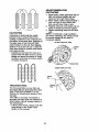
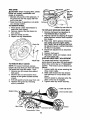
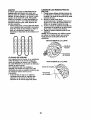
CULTIVATING
• Place blocks under right hand side of
tiller and remove hairpin clip and
clevis pin from right hand wheel•
2. Move wheel outward approximately 1
inch until hole in inner wheel hub
lines up with innerFOR
hole in axle.
ADJUSTWHEELS
3. Replace clevis pin and hairpin clip on
inside of wheel and remove blocks•
4• Repeat preceding steps on left hand
side•
NOTE: In extremely rough conditions
and while cultivating, the wheels should
be moved outward on the axle for
_
CULTIVATING
Cultivating
is destroying the weeds
between rows to prevent them from
robbing nourishment and moisture from
the plants. At the same time, breaking up
the upper layer of soil crust will help
retain moisture in the soil. Best digging
depth is 1" to 3" (2.5-7.5 cm). Lower the
outer side shields to protect small plants
from being buried.
• Cultivate up and down the rows at a
speed which will allow tines to uproot
weeds and leave the ground in rough
condition, promoting no further growth
of weeds and grass.
increased
stability.
OUTER VIEW OF TIRE
l vi'
airpin Cllip
0
0
0
0
0101010
OlOlOlO
0101010
0101010
INNER VIEW OF TIRE
Pin -------
TINE
SHEAR
!
Clevis
_
Hairpin
Clip J
PINS
The tine assemblies on your tiller are
secured to the fine shaft with shear pins
(See =TINE REPLACEMENT"
in the
Service and Adjustments section of this
manual).
If the tiller is unusually overloaded or
jammed, the shear pins are designed to
break before internal damage occurs to
the transmission.
• If shear pin(s) break, replace only with
those shown in the Repair Parts
section of this manual.
12
._
_
_-----__
_
_
f
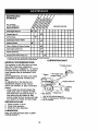
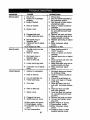
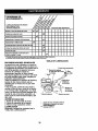
SCHEDULE
MAINTENANCE
_
Check EngineOil Level
I_
_//
I_ !
Change Engine Oil
I_1_
Oil Pivot Points
I_
InspectSpark Arraster/ Muffler
InspectAir Screen
V'
V/
Clean or Release Air Cleaner Cartridge
_2
Clean Engine Cylinder Fins
I_
Replace Spark Plug
I/
RH Gear Case Grease Fitting(1oz.)
I/
1 - Change morn o_tenwhen operating under a heavy load or in high ambient lempem_.
2 - Sei_Ice morn often when operating in dirty or dusty co_d_ons.
GENERAL
The warranty on this tiller does not cover
items that have been subjected to
operator abuse or negligence. To receive
full value from the warranty, the operator
must maintain tiller as instructed in this
manual.
Some adjustments will need to be made
periodically to properly maintain your
tiller.
All adjustments in the Service and
Adjustments section of this manual
should be checked at least once each
season.
• Once a year you should replace the
spark plug, clean or replace air filter,
and check tines and belts for wear. A
new spark plug and clean air filter
assure proper air-fuel mixture and help
your engine run better and last longer.
BEFORE
LUBRICATION CHART
RECOMMENDATIONS
EACH
* Throttle Control
** Engine
***RH Gear Case
Grease Fitting
Stake Pin
Shield
Hinges
* Idler Bracket
* Wheel Hub
SAE 30 OR 5W-30 Motor Oil
** Refer to Maintenance "ENGINE" Section
*** EP #1 Grease
USE
1. Check engine oil level.
2. Check tine operation.
3. Check for loose fasteners.
LUBRICATION
Keep unit well lubricated (See "LUBRICATION CHART').
13
5.
_:_CAUTION:Disconnect
spark plug wire
before performing any maintenance
(except carburetor adjustment) to prevent
accidental starting of engine.
Prevent fires! Keep the engine free of
grass, leaves, spilled oil, or fuel. Remove
fuel from tank before tipping unit for
maintenance.
Clean muffler area of all
grass, dirt, and debris.
Do not touch hot muffler or cylinder fins
as contact may cause bums.
Refill engine with oil. See "CHECK
ENGINE OIL LEVEL" in the Operation
section of this manual.
Oil drain
ENGINE
Oil Fill Plug
LU B RICATION
Use only high quality detergent oil rated
with API service classification SF-SJ.
Select the oil's SAE viscosity grade
according to your expected temperature.
AIR FILTER
Your engine will not run properly using a
dirty air filter. Clean the foam pre-cleaner
after every 50 hours of operation or every
season. Service paper cartridge every
100 hours of operation or every season,
whichever occurs first.
Service air cleaner more often under
dusty conditions.
1. Remove knob and cover. Lift air
cleaner assembly off stud.
SAEVISCOSI'WGRADES
*20
0
.,o
30
-,o
60
o
;o
100
80
_o
;o
,_
TEMPERATURERANGEANTICIPATEDBEFORENEXT OILCHANGE
NOTE: Although multi-viscosity
oils (5W30, 10W-30, etc.) improve starting in cold
weather, these multi-viscosity oils will
result in increased oil consumption when
used above 32°F (0°C). Check your
engine oil level more frequently to avoid
possible engine damage from running
low on oil.
Change the oil after every 50 hours of
operation or at least once a year if the
tiller is not used for 50 hours in one year.
Check the crankcase oil level before
TO SERVICE
2.
ENGINE
PRE-CLEANER
foam pre-cleaner
from air
3. Wash it in liquid detergent and water.
4. Squeeze it dry in a clean cloth.
NOTE: If very dirty or damaged, replace
pre-cleaner.
5. Reinstall pre-cleaner onto air filter.
6. Reinstall cover and secure with knob.
TO SERVICE
CARTRIDGE
1. Carefully remove cartridge to prevent
debris from entering carburetor.
Clean base carefully to prevent debris
from entering carburetor.
2. Remove foam pre-cleaner from air
filter.
starting the engine and after each five (5)
hours of continuous use. Add SAE 30
motor oil or equivalent. Tighten oil filler
plug securely each time you check the oil
level.
TO CHANGE
Remove
filter.
OIL
3. Clean cartridge by tapping gently on
flat surface. If very dirty or damaged,
replace cartridge.
4. Reinstall pre-cleaner onto air filter.
5. Reinstall cover and secure with knob.
IMPORTANT:
Petroleum solvents, such
as kerosene, are not to be used to clean
the cartridge. They may cause deterioration of the cartridge. Do not oil cartridge.
Do not use pressurized air to clean or dry
cartridge.
Determine temperature range expected
before oil change. All oil must meet API
service classification SF-SJ.
• Be sure tiller is on level surface.
• Oil will drain more freely when warm.
• Use a funnel to prevent oil spill on tiller,
and catch oil in a suitable container.
1. Remove drain plug.
2. Tip tiller forward to drain oil.
3. After oil has drained completely,
replace oil drain plug and tighten
securely.
4. Remove oil filler plug. Be careful not
to allow dirt to enter the engine.
14
MUFFLER
Do not operate tiller without muffler. Do not
tamper with exhaust system. Damaged
mufflers or spark arresters could create a
fire hazard. Inspect periodically and
replace if necessary. If your engine is
equipped with a spark arrester screen
assembly, remove every 50 hours for
cleaning and inspection. Replace if
damaged.
SPARK PLUG
Replace spark plugs at the beginning of
each tilling season or after every 50 hours
of use, whichever comes first. Spark plug
type and gap setting is shown in =PRODUCT SPECIFICATIONS" on page 4 of this
manual.
TRANSMISSION
Cover_
Stud
COOLING SYSTEM
Your engine is air cooled. For proper
engine performance and long life keep
your engine clean.
• Clean air screen frequently using a
stiff-bristled brush.
• Remove blower housing and clean as
necessary.
• Keep cylinder fins free of dirt and chaff.
Once a season, lubricate the right hand
gear case grease fitting with 1 oz. of EP #1
grease.
CLEANING
Do not clean your tiller when the engine
and transmission are hot. We do not
recommend using pressurized water
(garden hose, etc.) to clean your unit
unless the gasket area around the
transmission and the engine muffler, air
filter and carburetor are covered to keep
water out. Water in engine will shorten the
useful life of your tiller.
• Clean engine, wheels, finish, etc. of all
foreign matter.
• Keep finished surfaces and wheels free
of all gasoline, oil, etc.
• Protect painted surfaces with automotive type wax.
Housing
Screen
Muffler
_I, CAUTION: Disconnect spark plug wire
from spark plug and place wire where it
cannot come into contact with plug.
TILLER
TO ADJUST
HANDLE
HEIGHT
Select handle height best suited for your
tilling conditions. Handle height will be
different when tiller digs into soil.
1. First loosen handle lock lever.
2. Handle can be positioned at different
settings between =HIGH" and "LOW"
positions.
3. Retighten handle lock lever securely
after adjusting.
Handle (Low)
15
TIRE CARE
ACAUTIONi
When mounting tires, unless
beads are seated, ovednflation can
cause an explosion.
• Maintain 20 pounds of tire pressure. If
tire pressures are not equal, tiller will
pull to one side.
• Keep tires free of gasoline or oil which
can damage rubber.
TO REMOVE WHEEL
Repair
!
I__
/_..
_
/_-
_
(_ _
TO REPLACE
1.
]_
Washer
_b_ (Located
_
Behind
_\
GROUND
DRIVE BELT
Remove belt guard as described in
"TO REMOVE BELT GUARD".
2.
Remove old belt by slipping off engine
pulley first then remove from transmission pulley.
3. Place new belt in groove of transmission pulley and into engine pulley.
BELT MUST BE IN GROOVE ON TOP
OF IDLER PULLEY. NOTE POSITION
OF BELT TO GUIDES.
4. Check belt adjustment as described
below.
5. Replace belt guard.
6. Reposition wheel and replace clevis
pin and hairpin clip.
GROUND DRIVE BELT ADJUSTMENT
n
For proper belt tension, the extension
spring should have about 5/8 inch stretch
when drive control bar is in "ENGAGED"
position. This tension can be attained as
follows:
Hairpin Clip
TO REMOVE
_._
_,__
Nut
//and
Hairpin Clip and Clevis Pin
tire and reassemble.
__
.Guard
_//Hex
Screws _
1. Place blocks under transmission to
keep tiller from tipping.
2. Remove hairpin clip and clevis pin
from wheel.
3. Remove wheel and tire.
4.
B
/P_=======_l---'--'_,/
BELT GUARD
NOTE: For ease of removal, remove
hairpin clip and clevis pin from left wheel.
Pull wheel out from tiller about 1 inch.
1. Remove two (2) screws from side of
belt guard.
2. Remove hex nut and washer from
bottom of belt guard (located behind
wheel).
3. Pull belt guard out and away from unit.
4. Replace belt guard by reversing
above procedure.
1. Loosen cable clip screw securing the
drive control cable.
2. Slide cable forward for less tension
and rearward for more tension until
about
5/8 inch stretch is obtained while the
drive control bar is engaged.
3. Tighten cable clip screw securely.
pScrew
Engine Pulley\
Idler Pulley
Extension Spdng
Transmission Pulley
16
More Tension
TINE REPLACEMENT
• To maintain the superb tilling performance of this machine the tines should
be checked for sharpness, wear, and
bending, particularly the tines which
are next to the transmission. If the gap
between the tines exceeds 3-1/2
inches they should be replaced or
straightened as necessary.
• New tines should be assembled.
_CAUTION:
Tines are sharp. Wear
gloves or other protection when handling
tines.
A badly worn tine causes your tiller to
work harder and dig more shallow. Most
important, worn tines cannot chop and
shred organic matter as effectively nor
bury it as deeply as good tines. A tine this
worn needs to be replaced.
Sharpened tine edges will rotate
rearward from above.
Transmission
New "line
TinE
3-1/2"
MAX
Counter "line
Rotation
Shear Pin
Sharp Edg
Shear Pin .._
Sharp Edge
'_
Sharp
_
dge
Hairpin Clip
Sharp
Edge
17
Tine
ENGINE
Maintenance, repair, or replacement of
the emission control devices and systems, which are being done at the
customers expense, may be performed
by any non-road engine repair establishment or individual. Warranty repairs must
be performed by an authorized engine
manufacturer's service outlet.
TO ADJUST THROTTLE CONTROL
CABLE
1. The throttle control has been preset at
the factory and adjustment should not
be necessary. If adjustment is
necessary, proceed as follows:
2. With engine not running, move remote
throttle control lever to =FAST"
position.
3. If throttle lever on engine touches high
speed stop, no further adjustment is
necessary. If throttle lever does not
touch high speed stop, continue with
adjustment procedure.
4. Loosen cable clamp screw.
5. Move throttle lever up until it touches
high speed stop, and hold in this
position.
6. Tighten cable clamp screw securely.
TO ADJUST CARBURETOR
The carburetor has been preset at the
factory and adjustment should not be
necessary. However, engine performance can be affected by differences in
fuel, temperature, altitude or load. If the
carburetor does need adjustment, contact
your nearest authorized service center/
department
IMPORTANT: Never tamper with the
engine governor, which is factory set for
proper engine speed. Overspeeding the
engine above the factory high speed
setting can be dangerous. If you think the
engine-governed high speed needs
adjusting, contact your nearest authorized service center/department, which
has the proper equipment and experience to make any necessary adjustments.
,/
Clamp
--I / Screw
/ Casing
Wire
"-"-- Governor
Control
Lever
18
Immediatelyprepareyour tiller for storage
at the end of the season or if the unit will
not be used for 30 days or more.
_,CAUTION: Never store the tiller with
gasoline in the tank inside a building
where fumes may reach an open flame or
spark. Allow the engine to cool before
storing in any enclosure.
TILLER
NOTE: Fuel stabilizer is an acceptable
alternative in minimizing the formation of
fuel gum deposits during storage. Add
stabilizer to gasoline in fuel tank or
storage container. Always follow the mix
ratio found on stabilizer container. Run
engine at least 10 minutes after adding
stabilizer to allow the stabilizer to reach
the carburetor. Do not drain the gas tank
and carburetor if using fuel stabilizer.
ENGINE OIL
Drain oil (with engine warm) and replace
with clean oil. (See "ENGINE" in the
Maintenance section of this manual).
CYLINDER
1. Clean entire tiller (See =CLEANING" in
the Maintenance section of this
manual).
2. Inspect and replace belts, if necessary
(See belt replacement instructions in
the Service and Adjustments section
of thls manual).
3. Lubricate as shown in the Maintenanca section of this manual
4. Be sure that all nuts, bolts and screws
are securely fastened. Inspect moving
parts for damage, breakage and wear.
Replace if necessary.
5. Touch up all rusted or chipped paint
surfaces; sand lightly before painting.
ENGINE
FUEL SYSTEM
1. Remove spark plug.
2. Pour 1 ounce (29 ml) of oil through
spark plug hole into cylinder.
3. Pull starter handle slowly several
times to distribute oil.
4. Replace with new spark plug.
OTHER
• Do not store gasoline
to another.
from one season
• Replace your gasoline can if your can
starts to rust. Rust and/or dirt in your
gasoline will cause problems.
• If possible, store your unit indoors and
cover it to give protection from dust and
dirt.
IMPORTANT: It is important to prevent
gum deposits from forming in essential
fuel system parts such as the carburetor,
fuel filter, fuel hose, or tank during
storage, also, experience indicates that
alcohol blended fuels (called gasohol or
using ethanol or methanol) can attract
moisture which leads to separation and
formation of acids during storage. Acidic
gas can damage the fuel system of an
engine while in storage.
1. Drain the fuel tank.
2. Start the engine and let it run until the
fuel lines and carburetor are empty.
• Never use engine or carburetor cleaner
products in the fuel tank or permanent
damage may occur.
• Use fresh fuel next season.
• Cover your unit with a suitable protective cover that does not retain moisture.
Do not use plastic. Plastic cannot
breathe which allows condensation to
form and will cause your unit to rust.
IMPORTANT:
Never cover tiller while
engine and exhaust areas are still warm.
19
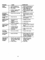
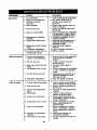
PROBLEM
Will not start
CAUSE
CORRECTION
1. Out of fuel,
2. Engine not "CHOKED"
properly.
3. Engine flooded.
4. Dirty air cleaner.
5. Water in fuel.
6. Clogged fuel tank.
7. Loose spark plug wire.
8. Bad spark plug or
improper gap.
9. Carburetor out of adjustment.
10.Oil soaked air filter.
Hard to start
1. Throttle control not set
properly.
2. Dirty air cleaner.
3. Bad spark plug or
improper gap.
4. Stale or dirty fuel.
5. Loose spark plug wire.
6. Carburetor
ment.
Loss of power
out of adjust-
1. Engine is overloaded.
1. Fill fuel tank.
2. See "TO START ENGINE" in
the Operation section.
3. Wait several minutes before
attempting to start.
4. Clean or replace aircleaner
cartridge.
5. Drain fuel tank and carburetor, and refill tank with fresh
gasoline.
6. Remove fuel tank and clean.
7. Make sure spark plug wire is
seated properly on plug.
8. Replace spark plug or adjust
gap.
9. Make necessary adjust
ments.
10.Replace air filter.
1. Place throttle control in
"FAST" position.
2. Clean or replace air cleaner
cartridge.
3. Replace spark plug or adjust
gap.
4. Drain fuel tank and refill with
fresh gasoline.
5. Make sure spark plug wire is
seated properly on plug.
6. Make necessary adjust
ments.
6. Stale or dirty fuel.
1. Set depth stake and wheels
for shallower tilling.
2. Clean or replace aircleaner
cartridge.
3. Check oil level/change oil.
4. Clean and regap or change
spark plug.
5. Drain and clean fuel tank
and refill, and clean carbure
tor.
6. Drain fuel tank and refill
7. Water in fuel.
7.
2.
Dirty air cleaner.
3. Low oil level/dirty oil.
4. Faulty spark plug.
5. Oil in fuel.
8.
9.
Clogged fuel tank.
Spark plug wire loose.
10.Dirty engine air screen.
11.Dirty/clogged
muffler.
12.Carburetor out of adjutsmerit.
13.Poor compression.
2O
with fresh gasoline.
Drain fuel tank and carburetor, and refill tank with fresh
gasoline.
8. Remove fuel tank and clean.
9. Connect and tighten spark
plug wire.
10.Clean engine air screen.
11.Clean/replace
muffler.
12.Make necessary adjustments.
13.Contact a Sears or other
qualified service center.
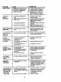
PROBLEM
Engine
overheats
CAUSE
CORREC_ON
1. Low oil level/dirty oil.
2. Dirty engine air screen.
3. Dirty engine.
4. Partially plugged muffler.
5. Improper carburetor
adjustment.
1. Check oil level/change oil.
2. Clean engine air screen.
3. Clean cylinder fins, air
screen, muffler area.
4. Remove and clean muffler.
5. Adjust carburetor to richer
position.
Excessive
bounce/difficult
handling
1. Ground too dry and hard.
o
Soil balls up or
clumps
1. Ground too wet.
.
Engine runs but
tillerwon't
move
1. Tins control is not
engaged.
2. V-belt not correctly
adjusted.
3. V-belt is off pulley(s).
Engine runs but
labors when
Ulling
1. Tilling too deep,
2. Throttle control not
properly adjusted.
3. Carburetor out of
adjustment.
.
Moisten ground or wait for
more favorable soil conditions.
Wait for more favorable
soil conditions.
Engage tins control.
2. Inspect/adjust V-belt.
3. Inspect V-belt.
1. Set depth stake for shallower
tilling.
2. Check throttle control setting.
3. Make necessary adjust
merits.
Tines Skip
over ground
1. Shear pin (s) broken.
1. Replace shear pin(s).
Hard to Shift
Into gear
1. Gears not timmed.
1. Briefly engage drive control
bar and release or rock tiller
forward and backward until
are able to shift gears.
Tiller shuts off
when drive
control bar
engaged
1. Shift lever set in between
counter rotating till position and forward rotating
till position.
2. Tines jammed.
21
1. Shift to either counter
.
rotating till position or
forward rotating
till position.
Clear tines.
Reglas de Seguridad ...................................
22
Programa de Mantenimiento ....................... 33
Garantfa ...................................................... 22
Servicio y Ajustes ...................................... 36
Especificaciones del producto .................... 24
Almacenamiento .......................................... 39
Identificaci6n de Problemas ........................ 40
Montaje ........................................................ 25
Operaci6n .................................................... 28
Partes de Repuesto ...... Vea el Manual Ingles
Mantenimiento ............................................. 33
lngl6s del Duefio
GARANTfA LIMITADA DE UNO AI_IO PARA LA CULTIVADORA CRAFTSMAN
Pot un (1) afio, a partir de ta fecha de compra, cuando esta Cultivadora Craftsman se mantanga,
lubdqua y afine segOn las instrucciones para la operaci6n y el mantenimiento en el manual del
duefio, Sears reparard, gratis, todo defecto en el material y la mano de obra.
Esta Garantfa no cubre:
• Adfculos qua sa desgastan duranta el uso normal tales como los brazos, las bujias, los filtros
de aire y las correas.
• Reparaciones necesarias debido al abuso o a la negligencia del operador, incluy_ndose a los
cig=3ei_alesdoblados y a la falta de mantanimiento del equipo seg_n las instrucciones qua se
incluyen en el manual del duefio.
• Si la Cultivadora Craftsman se usa para fines de arriendo, esta garantia se aplica solamente
por treinta (30) dfas a partir de la fecha de compra.
El Servicio de Garantfa esta disponible al devolver la cultivadora Craftsman al control
departamento de servicio Sears mds cercano en los Estados Unidos. Esta Garantfa sa aplica
solamente mientras el producto esta en uso en los Estados Unidos.
Esta Garantfa Is otorga derachos legales especfficos, y puede qua tambi6n tanga otros
derechos que varian de estado a estado.
SEARS, ROEBUCK AND CO., D/817WA, HOFFMAN ESTATES, IL 60179
IMPORTANTE: Esta Maquina cortadora es capaz de amputar las manosy los pies y de lanzar
objetos, si no se observan las instrucciones de seguddad siguientes se pueden producir
lesiones graves o la muerte.
ENTRENAMIENTO
• Use un envase de combustible aprobado.
• Lea el Manual del Duefio cuidadosamente.
• Nunca afiada combustible a un motor en
funcionamiento o caliante.
Familiarfcese completamente con los
controles y con el uso adecuado del equipo.
•Llene el estanque de combustible afuera
con mucho cuidado. Nunca Ilene el
Sepa cbmo parar la unidad y desenganchar
los controles r&pidamente.
estanque de combustible en un recinto
cerrado.
• Nunca permita qua los nifios operen el
equipo. Nunca permita que los adultos
• Vuelva a colocar la tapa del dep6sito de
operen el equipo sin los conocimientos
gasolina en forrna segura y limpie el
adecuados.
combustible derramado antes de volver a
arrancar.
• Mantenga el drea do operacibn despejada
de personas, especialmente nifios
• Use cordones de extensi6n y recept_culos,
pequefios y animales dom_sticos.
seg0n las especificaciones del fabricanta,
PREPARACI(_N
para todas las unidades con motores de
impulsi6n o con motoras de arranque
• Inspeccione cuidadosamento el drea en
el_ctrico.
donde se va usar el equipo y remueva los
objetos extrafios.
• Nunca trate de hacer ning_n ajuste
mientras que el motor est6 funcionando
• Desenganche todos los embragues y
(excepto en los casos especfflcamente
cambie a neutro antes de hacer arrancar el
motor.
recomendados por el fabricante).
OPERACI(_N
• No opera el equipo sin usar ropa exterior
adecuada. Use zapatos que mejoren el
• No ponga ni las manos ni los pies cerca o
equilibrio en superficies resbalosas.
debajo de las piezas rotatorias.
• Maneje el combustible con cuidado pues es
muy inflamable.
22
• Tenga mucho cuidado cuando opens o
cruce entradas para autom6viles de ripio,
senderos o caminos. Est6 alerta en Io que
sa refiere a los pefigros escondidos o al
trdfico. No Ileve pasajeros.
• Despu6s de pegarla a un objeto extraSo,
pare el motor, remueva el alambm de la
bujfa, inspaccions la cultivadora
cuidadosamente, para verificar si hay
dai_os, y repare el daSo antes de volver a
arrancar y operar la cultivadora.
• Tenga cuidado para evitar resbalarss o
caerse.
• Si la unidad empieza a vibrar anormalmente,
pare el motor y revfsela inmediatamente
para verificar la causa. La vibraci6n
normalmente es un aviso de problemas.
• Pare el motor cuando abandone la posici6n
de operaci6n.
• Tome todas las precaucionss posiblas
cuando deje la mdquina desatendida.
Desenganche los brazos, cambie a neutro
y pare el motor.
• Antes de limpiar, reparar e inspeccionar,
apagus el motor y aseg_mse que todas las
parfes en movimiento se hart detenido.
Desconecte el alambre de la bujia, y
mant_ngalo alejado de 6sta para evitar el
arranqus pot accidente. Desconecte el
cord6n en los motores eldctricos.
• No haga funcionar el motor en recintos
cerrados; los gases de escape son
peligrosos.
• Nunca opere la cultivadora sin las
protecciones, y las planchas adecuadas y
sin los demds dispositivosde seguridad en
su lugar.
• Mantenga a los ni_os y a los animales
dom6sticos alejados.
• No sobrecargue la capacidad de la
mdquina, tratando de cultivar a mucha
profundidad, muy rdpido.
• Nunca opera la mdquina a alias velocidades
en superficies resbalosas. Mire hacia atrds
y tenga cuidado cuando retroceda.
• Nunca permita la presencia de
espectadores coma de la unidad.
• Usa solamente accesorios y aditamentos
para la cuitivadora aprobados pot el
fabricante.
• Nunca opere la cultivadora sin buena
visibilidad o luz.
• Tenga cuidado al cultivar en terrono duro.
Los brazos pueden quedarse agarrados en
el suelo e impulsar a la cultivadora hacia
adelante. Si esto sucede, suslte los mangos
y no restrinja la mdquina.
MANTENIMIENTO
Y
ALMACENAMIENTO
• Mantenga los accesorios y aditamantos de
la mdquina en buenas condiciones para el
funcionamiento.
• Revise las clavijas de seguro, los pemos de
montaje del motor y otros pemos, a
intervatos frecuentes, para verificar si estdn
apretados en forma segura y asegurarse
que el equipo est6 en buenas condiciones
de funcionamiento.
• Nunca guarde la mdquina con combustible
en el estanque de combustible dentro de un
edificio en donde hay fuentes de ignici6n
presentes, tales como calentadores de
agua odel ambiente, secadoras de ropa u
otms artefactos parecidos. Permita que se
enfrfe el motor antes de guardarlo en algdn
lugar cermdo.
• Siempre refidrase a las instruccionesen la
gufa del operador para vet los detalles de
importancia si la cultivadora va a ser
guardada pot un perl'odode tiempo largo.
_Busque esta sfmbolo que se_ala las
precauciones de seguridad de imporfancia.
Quiere decir - iIIATENCI6N??! iiiESTE
ALERTO!?! SU SEGURIDAD ESTA COMPROMETIDA.
APRECAUCI(_N: Siempre desconecte el
alambre de la bujfa y p6ngalo donde no pueda
entrar en contacto con la bujfa, para evitar el
arranque pot accidente, durante la
preparaci6n, el transporfe, el ajuste o cuando
se hacen reparaciones.
_ADVERTENClA:
El tubo de escape del
motor, algunos de sus constituyentes y
algunos componentes del vehfculo contienen
o desprenden productos quimicos conocidos
en el Estado de California come causa de
c_ncer y defectos al nacimiento u otros daSos
reproductivos.
23
ESPECIFICACIONES
DEL PRODUCTO
.3APAClDADDE
3ASOLINA:
3 CUARTOS
SIN PLOMO, REGULAR
_CEITE(API-SF-SJ):
;APACIDAD: 20 OZ.)
SAE 30 (SOBRE 32°F)
SAE 5W-30
(DEBAJO 32°F)
CHAMPION RC12YC
BUJIA :
ABERTURA: 0,030")
RESPONSABILIDADES
DEL CLIENTE
• Lea y observe las raglas de seguddad.
• Siga un programa regular de mantenimiento,
cuidado y uso de su cultivadora.
• Siga las instrucciones descritas en las
secciones "Mantenimiento" y
=Almacenamiento" de este Manual del
DueSo.
_s, DVERTENClA: Esta unidad viene
equipada con un motor de combusti6n intemo
y no se debe usar sobre, o cerca, de un
terreno no desarrollado cubierto de bosques,
de arbustos o de c6sped, a menos que el
sistema de escape del motor venga equipado
con un amortiguador de chispas que cumpla
con las leyes locales o estatales (si existen).
Si se usa un amortiguador de chispas, el
operador debe mantenedo en condiciones de
trabajo eficientes.
En el estado de California, la ley axiga Io
anterior (Secci6n 4442 del "California Public
Resources Code" [Decreto de Recursos
P_blicos de California]). Otros estados
pueden contar con otras leyes parecidas. Las
leyes federales se aplican en las Uerras
federales. Su centro de Servicio rods cercano
tiene disponible amortiguadoras de chispas
para el silenciador. (Vea la secci6n de Partes
de Repuesto en el manual Ingl6s del due_o.)
FELIClTAClONES por la compra de su
Cultivadora Seara. Ha sido diseSada,
planificada y fabricada para dade la mejor
confiabilidad y el mejor rendimiento posible.
En el caso de que sa encuentre con coalquier
problema que no pueda solucionar fdcilmente,
haga el favor de ponerse en contacto con su
centro de sarvicio cualificado. Sears cuenta
con tdcnicos bien capacitados y competentes
con herramientas adecuadas para dade
servicio o para raepararsu unidad.
Haga el favor de leer y de guardar este
manual. Estas instrucciones le permitirdn
montar y mantener su cultivadora en forma
adecuada. Siempre observe las =REGLAS DE
SEGURIDAD."
Estos accesodos estaban disponibles cuando se compr6 la cultivadora. Tambidn estdn
disponibles en la mayorfa de las tiendas de Sears yen los centros de servicio. La mayoria de las
tiendas Sears tambidn pueden ordenar partes de repuesto para usted, si les proporciona el
n_mero del modelo de su cultivadora.
MOTOR
BUJ_A
RENDIMIENTO
SILENCIADOR
LATADEGASOLINA
kCEn_DELMOTOR
ESTA_R
DE LA CULTIVADORA
ABRIDOR DIE $URCOB
MANTENIMIENTO
CORREA
FILTRODEAIRE
I
DE LA CULTIVADORA
BRAZOS
CLAVIJA DE SEGURO
24
ABRAZADERA
DE HORQUILLA
Su cultivadora nueva ha sido montada en la
fdbdca, con la excepci6n de aquellas partes
que se dejaron sin montar por razones de
envio. Para asegurarse que la cultivadora
operard en forma segura y adecuada, todas
las partes y los art|culos de ferreteda que
monte tienen que estar apretados en forma
segura. Use las herramientas correctas,
segdn sea necesado, pare asegurarse de que
queden apretadas en forma segura.
HERRAMIENTAS
NECESARIAS
PARA
EL MONTAJE
Se le facilitar& el montaje si cuenta con un
juego de Ilaves de tubo. Se han enumerado los
tamafios estdndar de las Ilaves.
(1) Cuchillo para todo uso
(1) Cortador de alambres
(1) Destomillador
(1) Medidor de presi6n de las Ilantas
(1) Par de alicates
(1) Llave de 9/16"
POSlClON DEL OPERADOR
Cuando en este manual se mencionan los
t6rminos =lado derecho" o =lado izquierdo" se
refiere a cuando usted se encuentra en la
posici6n de operaci6n (parado/a detrd.sde los
mangos de la cultivedora).
PARTE DELANTERA
LADO
IZQUIERDO
LADO
DERECHO
POSICI6N DEL
OPERADOR
CONTENTS OF HARDWARE
PACK
©
(2) Cierres del mango
(1) Perno portadores
3/8-16 UNC x 1 clase 5
(1) Abrazaderas
(1) Tuerca de
seguridad
de centro
3/8-16
UNC
(1)Abrazadera
de cable
de
(1) Perno articulado
3/8-16 UNC Clase 5
,
o]
(2) Clavijade seguro
& retencion
(1) Arandela plana
13/32 x 1 x 11 Ga.
©
(1)Palanca
25
de cierre del mango
DESEMPAQUE
DE LA CAJA DE
CARTON
_PRECAUCI6N:
Tenfa cuidado con las
grapas expuestas cuando maneje o deseche
los materiales de la caja de cart6n.
IMPORTANTE: Cuando desempaque y monte
la cultivadora, tenga cuidado de no estirar o
enredar los cables.
1. AI mismo tiempo que se sujeta el conjunto
del mango, code las ligaduras del cable
que aseguran el conjunto del mango al
bastidor superior y a la estaca de
pmfundidad. Permita que el conjunto del
mango descanse en la cultivadora.
2. Remueva el bastidor superior de la caja de
cart6n.
3. Lentamente, saque el conjunto del mango
hacia arriba y p6ngalo en la pade superior
de la caja de cart6n.
4. Code la esquina del lado derecho delantera
y la trasera de la caja de cart6n, tienda en
el suelo la pared lateral de la caja de
cart6n.
5. Remueva el material de empaque del
conjunto del mango.
6. Separe la varilla de cambio del conjunto del
mango.
Conjuntodelmango
posocldn"Ardba"
Apriete la palanca de
cterredel mangopara
sujetada
Sualta la palanca d_
moverta
4.
Inserte el pemo de pivote de la pade
delantera de la placa y apriete en forma
segura.
5. Corte las esquinas restantes del cart6n y
p6ngalas planas.
6. Baje el conjunto de mango. Apdete la
tuerca del pemo de acarreo para que el
mango pueda moverse con alguna
resistancia. Esto facilitara el ajuste.
7. Ponga la arandela plana en el extremo
roscado de la palanca de cierre del mango.
8. Insede ]a palanca de cierre del mango a
travds de la base del mango y de la caja
de engranaje. Atomille la palanca de
seguridad del mango, justo Io suficiente
como para sujetar la palanca en su lugar.
9. Inserte el segundo cierre del mango (con
los dientes hacia adentro) en la ranura en
la base del mango (justo dentro de la
arandela).
10. Levante el conjunto del mango a la
posici6n mas alta, y apriete la palanca de
cierre del mango, en forma segura,
rotdndola en el sentido de las manillas del
reloj. Si se deja el conjunto del mango en
la oposici6n mas alta, serd mas f_.cil
conectar la palanca de cambios.
ArandelaPlana
CierredelMango
Palancade
CajadeCambio
CiorredelMango
Cambio
_nto
del
INSTALACI(_N DEL MANGO
1. Inserte un cierre del mango (con los
dientes mirando hacia afuere) en la
muesca de la caja de cambio. (Aplique
grasa en el lado liso del cierre del mango
para ayudar a mantenerlo en su lugar
hasta que el conjunto del mango se baje a
su posici6n.)
Vista desdeel lado derechode lacultlvadora
Conjuntodel Manfo
e_ t dela Cajade Cambio
Pemoportador
trasoro
CierredelMango
&
Base dol Mang_
2. Agarre el coniunto del mango. Mant_ngalo
en la posici6n "arriba." Asegarese que el
cierre del mango permanezca an la muesca
de la caja de cambio. Deslice el conjunto del
mango a su posici6n.
3. Rote el conjunto del mango hacia abajo.
Inserte el pemo podador trasere primero,
con la cabeza del perno en el lado
izquierdo de la cultivadora y ponga
sueltamente la tuerca de seguridad.
26
Boulonde
/_L
pivot
Tuercas de Seguridad
INSERCI6N
DE LA ABRAZADERA
DEL
CABLE
• Inserte la abrazadera del cable de pldstlco
dentro del agujero en la parte trasera de la
columna del mango. Empuje los cables
dentin de la abrazadera.
Abrazadera de Horquilla
Indlcador de la
Palanca de Cambio
Varillade Cambio
Columna
de4
Mango
Cables
Abrazaderadel
Cable
CONEXl6N DE LA VARILLA DE CAMBIO
1. Inserte el extremo de la varilla de cambio
qua estd rods alejado de la dobladura, en
el agujero del indicadorde la palanca de
cambio.
2. Inserta la abrazadera de horquilla a trav6s
del agujero de la vadlla de cambio para
asegurarla con la junta de la abrazadera
sobre el lado derecho.
REMOCI(3N DE LA CULTIVADORA
DE
LA CAJA
1. Ajuste el conjunto del mango a la posici6n
lamas baja. Asegdrese que el mango de
cierre est# bien segum.
2. AsegL_msequa el indicador de la palanca
de cambio est6 an la posici6n neutro =N".
3. Incline la cultivadora hacia adelante
levantando el mango. Separe la cubierta de
cart6n de la defensa de nivelaci6n.
4. Rote el mango de la cultivadora a la
derecha y tfrela fuera de la caja de cart6n.
REVISli_N DE LA PRESI6N DE LAS
LLANTAS
Las Ilantas en su unidad se inflaron demasiado
en la fdbrica pot razones de envio. Es
importante que las Ilantas tengan la misma
presi6n y que 6sta sea la correcta para
obtener el mejor rendimiento en el labrado.
• Reduzca la presi6n de las Ilantas a 20 PSI.
ALTURA DEL MANGO
• Se puede ajustar la altura del mango en la
mejor forma qua le acomode al operador.
(Vea =PARAAJUSTAR LA ALTURA DEL
MANGO" an la secci6n de Servicio y
Ajustes de este manual.)
Vadllade cambio
_1"_
Adjunteesteextremoal indicadorde
lapalancade cambio
27
Estos sfmbolos pueden apareser sobm su cultivadora en la literature proporcionada con el
producto, aprenda y comprenda sus significados.
CONOZCA
SU CULTIVADORA
LEA ESTE MANUAL DEL DUEI_IO Y I.AS REGLAS DE SEGURIDAD ANTES DE OPERAR SU
CULTIVADORA
Compare las ilustreclones con su cultlvadore pare famlllarlzarse con la ublcacl6n de los
dlvereoa controles y ajustes. Guarde este manual para future referencla.
_U_ERI1ENC_ ENCl_OmO
AP/U3,_DO
_
BJ_laLE
de la aceleracibn
Palanca de cambio
BarrE :lecontrol de
la impulsi_n
Indicador de la palanca
Estaca de
Profundidad
©
Defensa de
Defeesa lateral
exterior
Mango del
arrancadorde
culateo
Nuestras cultivadoras cumplen con los est&ndares de seguddad del
American National Standards Institute.
ESTACA DE PROFUNDIDAD - Controla la
profundidad a la coal excavard la cultivadora.
BARRA DE CONTROL DE LA IMPULSION Se usa para enganchar los brazos.
DEFENSA DE NIVELACI(_N - Nivela el suelo
labrado.
DEFENSA LATERAL EXTERIOR -Ajustable
para no enterrar las plantas pequeSas.
MANGO DEL ARRANCADOR DE CULATEO
- Se usa para hacer arrancar el motor.
PALANCA DE CAMBIO - Se usa para
cambiar los engranajes de la transmisibn.
INDICADOR DE LA PALANCA DE CAMBIO
- Muestra en qud cambio de engmnaje se
encuentra la transmisi6n.
CONTROL DE LA ACELERACI(_N Controla la velocidad del motor.
28
La opemci6n de cualquier cultivadora puede hacer que salten objetos extra_s
anteojos de seguridad o pmtecoiones para los ojos antes de hacer arrancar su
cultivadora o mientras est6 labrando con dlla. Recomendamos el uso de la
_
entin dede
sus
ojos, Io que
puedeamplia,
producir
dai_os
en _stos.
Siempre
use
m_Lqcara
seguridad
de visi6n
para
usograves
sobra los
espejuelos
o anteojos
de seguddad est_ndan
COMO USAR SU CULTIVADORA
ES DIFfCIL CAMBIAR LAS MARCHAS
Sepa c6mo operar todos los controles antes
• Enganche lentamente la barra de control de
de agregar combustible y aceite o antes de
la transmisi6n y suelte o bascule la
tratar de hacer arrancar el motor,
cultivadora hacia adelante y hacia atrds
PARADA
hasta que sea posible cambiar las marchas.
BRAZOS Y LA IMPULSI6N
ESTACA DE PROFUNDIDAD
La estaca de profundidad puede levantarse o
1. Suelte la barra de control de la impulsi6n
bajarse para permitide un labrado m_,s versatil
para parar el movimiento,
o para facilitar el transporte de su cultivadora.
2, Mueva la palanca de cambio a la posici6n
de neutro (=N").
MOTOR
• Mueva el control de la aceleraci6n a la
posici6n de =PARADA" (STOP). Si equipado
con un interruptor de parada, mueva el
interruptor a la posici6n de =PARADA"
(STOP).
AVISO: Nunca use la estrangulaci6n para
parar el motor,
Barrade controldela
!mpulsi_n enla posici6n_.:/.:'.:._
Enganchada'_._j.-_,'_
Controldela
_:'
leraci6n
Barrade'controldela \\
"o
impulsibn
enla posici6n_
_,\ Palancade
_ / camb]o
le
Labradomenos
prolunde
(Cultivating)
T_rte
LabradeMds
profundo
Estacadeprofundidad
1. Suelte la clavija de la estaca de
profundidad. 33re la estaca de profundidad
LABRADO
hacia arriba para aumentar la profundidad
del labrado. Ponga la clavija de la estaca
de profundidad en el agujero de la estaca
de profundidad para cerrarla en su
posici6n.
2. Ponga el indicador de la palanca de cambio
en la (_T,)posici6n.
3. Sujetela barra de control de la impulsi6n
en contra del mango para empezar con el
movimiento de labraci6n. Tanto los brazos
como las ruedas van a girar.
4. Mueva el control de la aceleraci6n a la
posici6n de =RAPIDO" (FAST) para un
labrado profundo. Para cultivar, el control
de la aceleraci6n puede ser ajustado a
cualquier velocidad deseada, dependiendo
de cudn rdpido o cudn lento desee hacer
el cultivo.
IMPORTANTE: Siempre suelte la barm de
control de la impulsibn antes de mover la
OPERACI(_N DE LOS BRAZOS - CON
IMPULSI(_N DE RUEDAS
• Siempra suelte la barra de control de la
impulsibn antes de mover la palanca de
cambio a otra posici6n.
• El movimiento de los brazos se Iogra
moviendo la palanca de cambio a la
posicibn (_,) labrado y enganchando la
barra de control de la impulsi6n.
MARCHA HAClA ADELANTE - RUEDAS
SOLAMENTE/BRAZOS
PARADOS
• Suelte la barra de control de la impulsi6n y
mueva el indicador de la palanca de cambio
a la posici6n "F" (marcha hacia adelante).
Enganche la barra de control de la impulsi6n
palanca de cambio a otra posici6n.
y la cultivadora se moverd hacia adelante.
Clavija de la estaca de
MARCHA ATRAS - RUEDAS SOLA MENTE/
profundidaden la posici6n
\
=Suelta"
BRAZOS PARADOS
1. NO SE PARE DIRECTAMENTE DETRAS
DE LA CULTIVADORA.
2. Suelte la barra de control de la impulsi6n.
3. Mueva el control de la aceleraci6n a la
posici6n de =LENTO" (SLOW).
Posici6n
4. Mueva el indicador de la palanca de
"Cerrada"
cambio a la posici6n de =R" (mamha
atrds).
TLlerc_
5. Sujete la barra de control de la impulsi6n
"B"
Protecteur
en contra del mango para hacer arrancar
en movimiento a la cultivadora,
29
lateral
GIRO
1. Suelte la barra de control de la impulsi6n.
2. Mueva el control de la aceleraci6n a la
posici6n de "LENTO" (SLOW).
3. Ponga el indicador de la palanca de cambio
en la posici6n de "F" (mamha hacia
adelante). Los brazos no van a girar.
4. Levante el mango para levantar los brazos
fuera del suelo.
5. Mueva el mango en la direcci6n opuesta
an la que desea girar, con cuidado de
mantener los pies y las pismas alejados
de los brazos de la cultivadora.
6. Cuando haya completado su vuelta, suelte
la barra de control de la impulsi6n y baje el
mango. Ponga la palanca de cambio en la
posici6n labrado y mueva el control de la
aceleraci6n a la velocidad deseada. Para
empezar a cultivar, sujete la barra de
control de la impulsi6n en contra del
mango.
PARA EL TRANSPORTE
_PRECAUCl6N:
Antes de levantada o
transportada, permita que el motor de la
cultivadora y el silenciador se enfrfen.
Desconecte el alambre de la bujfa. Drene la
gasolina del estanque de combustible.
EN EL JARD|N
1. Suelte la clavija de la estaca de
pmfundidad. Mueva la estaca de
profundidad hacia abajo, al agujero
superior, para transportar la cultivadora.
Ponga la clavija de la estaca de profundidad en el agujero de la estaca de
pmfundidad para asegurarla en su lugar.
Esto impide que los brazos se arrastren
por el suelo.
2. Ponga el indicador de la palanca de cambio
en la posici6n de "F" (marcha hacia
adelante) para el transports.
3. Sujete la barra de control de la impulsi6n
en contra del mango para empezar con el
movimiento de la cultivadora. Los brazos
no van a girar.
4. Mueva el control de la aceleraci6n a la
velocidad deseada.
EN LA ClUDAD
1. Desconecte el alambre de la buj|a.
2. Drone el estanque de combustible.
3. Transp6rtela en la posicibn derecha hacia
arriba para evitar la fuga del aceite.
ANTES DE HACER ARRANCAR
EL
MOTOR
IMPORTANTE: Tenga mucho cuidado de no
permitir que entre mugre al motor cuando
revise o a_ada aceite o combustible. Use
aceite y combustible limpios y gudrdelos en
envases aprobados, limpios y con tapa. use
smbudos para rslleno limpios.
REVISI6N DEL NIVEL DEL ACEITE DEL
MOTOR
El motor en su unidad ha sido enviado desde
la fdbrica lleno con aceite de calidad para el
verano SAE 30.
1. Con el motor nivelado, llmpie un drea
alrededor del tap6n del dep6sito para
relleno del aceite y remueva el tap6n.
2. Con el motor nivelado, d aceite del motor
debe Ilegar hasta el punto de derramarse.
• Para verificar la capacidad aproximada vea
uESPECIFICACIONES DEL PRODUCTOen la pdgina 24 de este manual. Todo el
aceite tiene que cumplir la clasificaci6n de
servicio API SF o SJ.
• Para la operacibn en clima frfo, debe
cambiarse el aceite para facintar el arranque
(vea la =TABLA DE VISCOSIDAD DEL
ACEITE" an la secci6n de Mantenimianto en
este manual).
• Para cambiar el aceite del motor, vea la
secci6n de Mantenimiento en este manual.
Tap6n de depositode
relieno de aceite
AGREGUE GASOLINA
•Llene el estanque de combustible. Use
gasolina regular, sin plomo, nueva y limpia.
(El uso de gasolina con plomo aumsntar_.
los dep6sitos de bxido de plomo y carbono
y se reducird la duraci6n de la v61vula.)
IMPORTANTE: Cuando se opero en
temperaturas por debajo de 32°F (0°C) use
gasolina de calidad de inviemo, limpia y nueva
para ayudar a asegurar un buen arranque en
clima frlo.
_,DVERTENClA:
La sxperiencia ha indicado
que los combustibles mezclados con alcohol
(conocidos como gasohol, o el uso de etanol o
metanol) pueden atraer la humedad, la que
conduce a la separaci6n y formaci6n de
dcidos durante el almacenamiento. La gasolina
acidica pueds daSar el sistema del combustible de un motor durante el almacenamiento.
Para evitar problemas con el motor, se
debe vaclar el sistema de combustible
antes de guardarlo por un perfodo de 30
dfas o rods. Vacfe el estanque de combustible, haga arrancar el motor y hdgalo
funcionar hasta que las Ifneas del combustible
y el carburador queden vacfas. La pr6xlma
temporada use combustible nuevo. Vea la
secci6n de Almacenamiento para mds
informaci6n. Nunca use productos de limpieza
para el motor o para el carburador an el
estanque del combustible pues se pueden
producir daSos permanentes.
30
_PRECAUCI6N:
Uene el estanque de
combustible hasta dentro de 1/2 pulgada de la
parte superior para evitar los derrames y para
permitir que se expanda el combustible. Si por
casualidad se derrama la gasolina, aieje la
mdquina del dma del derrame. Evita crear
cualquiara fuente de ignici6n hasta que se
hayan desaparecido los gases de la gasolina.
No Io liana demasiado. Limpie el aceita o el
combustible dermmado. No guarde, derrame o
use la gasolina cerca de una llama expuesta.
PARA HACER ARRANCAR
EL MOTOR
_I, PRECAUCI(_N: Mantenga la barra de
control de la impulsi6n en la posici6n
"DESENGANCHADO = cuando haga arrancar
el motor.
Cuando esta empezando un motor por la
primere vez o si el motor se ha quedado sin
gasolina, serd necesario varios intentos para
mover la gasolina desde el estanque al motor.
1. AsegOrese que el alambre de la bujia est6
conectado an forma adecuada y que la
vdlvula de cierre de la gasolina este
abierta.
2. Ponga la palanca de camblo a la posici6n
de (NEUTRO) "N".
3. Ponga la paienca de cambio a la posici6n
de "RAPIDO" (FAST).
4. Mueva la v_.lvula de cierre del combustible
1/4 tumo para ABRIR.
5. Mueva el control de la estrangu.laci6na la
posici6n de ESTRANGULACION.
6. Agarre el mango del arrancador de culateo
con una mano y el mango de la cultivadora
con la otra mano. "13reel cord6n hacia
afuera, lentamente, hasta que el motor
legue al comienzo del ciclo de la
compmsi6n (el cord6n se sentird un poco
mas duro an esta momento).
7. Tire el mango del arrancador de culateo
rdpidamenta. No permita qua el mango del
arrancador se devuelva abruptamente en
contra del arrancador. Vuelva a repeUr,si
Io es necessario.
AVISO: Si el motor se enciende pero no
comienza, mueva el control de la
estrengulaci6n al medio. "13redel mango del
arrancador de retroceso hasta qua el motor
comience.
8. Cuando comience el motor y al mismo
tiempo que se caliente, mueva,
lentamente, el control de la estrangulaci6n,
a la posici6n de =MARCHA'.
AVISO: Un motor caliente requiere menos
estrangulaci6n para empezar.
9. Mueva el control de la acelereci6n a la
posici6n de funcionamianto deseada.
10. Permita que se calienta el motor por unos
cuantos minutos antes de enganchar los
brazos.
AVISO: A mucha altura (sobre 3000 pies) o en
cllmas fdos (debajo de 40 ° F [4° C]) puede
que la mezcla del combustible del carburador
necesita ajusta, para obtaner el mejor
resultado del motor. Vea =PARA AJUSTAR EL
CARBURADOR" en la secci6n de Serviclo y
Ajustes de este manual.
AVISO: Si el motor no arranca, vea la guie de
identiflcaci6n de pmblemas.
Choke control
de la estrangulacibn
Mang
CONSEJOS
PARA LABRAR
APRECAUCI6N:Antas
de acostumbrarse a
manejar su cultivadora, empiece el uso de
6sta en el terreno con la aceleraci6n en la
posici6n de "lento" (SLOW).
• El iebrar quiere decir el excavar, dar vuelta
y romper el suelo duro antes de plantar. El
suelo suelto y blando permita el desarrollo
de las raices. La mejor profundidad de
labrar es 4' a 6". La cultivadora tambi6n
puede despejar el suelo de las malezas
indeseables.
La descomposici6n de estas malezas
enriquece el suelo. Dependiendo del clima
(lluvia o viento), puede ser recomendable
labrar el suelo a fines de la tamporada de
cultivo para acondicionar el suelo at_n mds.
• Pare facilitar el manejo de su cultivadora,
deje alrededor de 8 pulgadas de terreno sin
labrar entre la primera y la segunda pasada
para el labrar. La tercera pasada se hace
entre la primera y la segunda.
• Va a descmbrir que el labrado se facilita si
deja una fila sin labrar entre las pasadas.
Entonces vuelva de nuevo entre las filas de
cult'No. Hay dos razones para hacer 6sto.
Primero, las vueltas amplias se puedan
realizar con rods facilidad que las cerradas.
Segundo, la cultivadora no estard
empujdndose a si misma y a usted hacia la
pr6xima hilera.
• No se afirme en el mango. Esto saca el
peso de la ruedas y reduce la trecci6n. Para
atravesar una secci6n muy diffcil de tierra
herbosa o de suelo dum, aplique una
presibn hacia arriba en el mango o baje la
estaca de profundidad.
31
CULTIVO
El culUvo quiere decir la destrucci6n de las
malezas entre las hileras, para evitar que
6stas le robert la nutdci6n y la humedad alas
plantas. AI mismo tiempo, si se tempe la capa
supedor de la costra del suelo, 6ste puede
retener la humedad. La mejor profundidad de
excavaci6n es de 1" a 3". Baje las defensas
laterales exteriores para evitar enterrar las
plantas peque_as.
• Cultive hacia arriba y hacia abajo las hileras
a una velocidad que le permita a los brazes
sacar las rafces de las malezas y dejar el
suelo en condiciones dsperas, para
desalentar el desarrollo de las malezas y el
cdsped.
AJUSTE DE I.AS RUEDAS PARA EL
CULTIVO
1. Ponga bloques debajo del lade derecho de
la cultivadora y remueva la abrazadera de
horquilla y la clavija de horquiIla de la rueda
del lade derecho.
2. Mueva la rueda hacia afuera,
aproximadamente 1 pulgada, hasta que el
agujero en el cube de la rueda interior se
alinee con el agujero interior en el eje.
3. Vuelva a colocar la clavija de horquilla y la
abrazadera de horquilla en la parte intedor
de la rueda y remueva los bloques.
4. Repita los pasos anteriores para el lade
izquierdo.
AVISO: En condiciones muy difl'cilescuando
se cultiva, las ruedas tienen que moverse
hacia afuera en el eje para aumentar la
estabilidad.
OOOOI O
O O OIOI ©
OOOOI
OOOO1
VISTA EXTERIOR
DE LA LLANTA
t de
horquilla
de horquilla
CLAVIJAS DE SEGURO
Los conjuntos de los brazes de su cultivadora
estdn afirmados en eje de los brazes per
medio de clavijas de seguro (vea "CAMBIO
DE LOS BRAZES" en la secci6n de Servicio y
Ajustes de este manual).
Si la cultivadora estd muy cargada o
atascada, las clavijas de seguro ban side
disei_adas para que se quiebren antes de que
se produzcan daSos internes en la
transmisi6n.
• Si las clavijas de seguro se quiebran,
cdmbielas solamente per aquellas que
aparecen en la secci6n de Partes de
Repuesto en el manual Inglds del dueSo.
VISTA INTERIOR DE LA LLANTA
O,aviia
dohorqu,,
Abrazadera
32
MANTENIMIENTO
PROGRAMA
,,_
DE
QUE COMPLETE
_/_o_,
_///_/
SU
SERVICIO REGULAR
Revisar el nivel del aceite del motor
/_'/_TZO
l# #
_
Ip#
Camblar el aceite del motor
<2
Aceitm" los puntos de pivote
li_
Inspeccionar el supresor del silenclador
Inspeccionar la rejilla de aim
Umplar/cambiar
Umplar
DE SERVIClO
lie
k/'
el cartucho del filtro de sire
_2
las aletas del cilindro del motor
I_
Cambiar la buj|a
IP/
Raccord de graisse du c6t6 droit de la
botte de vitesse (1 onza)
k_4
1- _
rn_ menudocuandoseopera bajocargapesadao e_ amblentesconalias tempera_J_
2. OarNMClO m6s a menu<locuandose opereen _
suclaso polvorosas
TABLA
RECOMENDACIONES
GENERALES
La garanta de esta cultivadora no cubre los
artfculos que hart estado sujetos al abuso o a
la negligencia del operador. Para recibir todo el
valor de la garantl'a, el operador tiene que
mantener la cultivadora segdn las
instrucciones descritas en este manual.
Hay algunos ajustes que se tienen que hacer
en forma ped6dica para poder mantener su
cultivadora adecuadamente.
Todos los ajustes en la secci6n de Servicio y
Ajustes de este manual tienen que ser
revisados por Io menos una vez por cada
temporada.
• Una vez al a_o, cambie la bujia, Iimpie o
cambie el filtro de aire y revise si los brazos
y las correas estdn desgastadas. Una bujfa
nueva y un filtro de aire limpio aseguran una
mezcla de aim-combustible adecuada y le
ayuda a que su motor funcione mejor y que
dure mds.
ANTES DE CADA USO
1. Revise el nivel del aceite del motor.
2. Revise la operacibn de los brazes.
3. Revise si hay sujetadores sueltos.
LUBRICACI(_N
Mantenga la unidad bien lubricada (vea la
"TABLA DE LUBRICACI(_N').
DE LUBRICACI6N
* Controlde laaceleraci6n
...
--orf jF-_/
_//_
_
_
_
_ Clavijade la
/
estacade
_IundNad
__*
I
Aceitedemotor SAE 30 O 5W-30
Refieraso a lasecci6n delmotor,
MANTENIMIENTO"
*** Graisse de EP #1
**
33
I_lsabrade
la defe,nsa.,
APRECAUCI(_N: Desconecte el alambre de
la bujfa antes de dar mantenimiento (excepto
por el ajuste del carburador) para evitar que el
motor arranque por accidents.
lEvite los incendios! Mantenga el motor sin
cdsped, hojas, aceite o combustible
derramado.
Remueva el combustible del estanque antes
de incliner la unidad para darle mantenimiento.
Limpie el cdsped, la mugre y la basura del
drea del silenciador.
No toque el silenciador caliente o las aletas del
cilindro, puss el contacto puede producir
quemaduras.
4.
Remueva el tap6n del depdsito de relleno
de aceite. Tenga cuidedo de no permitir
que la mugre entre al motor.
5. Vuelva a Ilenar el motor con aceite. Vea
"REVISION DEL NIVEL DEL ACEITE DEL
MOTOR CON ACEITE n en la seccidn de
Operacidn de ese manual.
MOTOR
LUBRICACIdN
Use solamente aceite de detergents de alta
calidad clasificado con la clasificacidn SF-SJ.
de servicio API. Seleccione la calidad de
viscosidad SAE segOn su temperature de
operacidn esperada.
CAUDADES DE V1SCOdlDAD DE SAE
AVISO: A pesar de que los aceites de
multiviscosidad (5W-30, 10W-30, etc.)
mejoran el arrenque en clima frfo, estos
aceites de multiviscosidad van a aumentar el
consumo de aceite cuando se usan en
temperaturas sobre 32°F (0°C).
Revise el nivel del aceite del motor mds a
menudo, para evitar un posible dafio en el
motor, debido a que no tiene suficiente aceite.
Cambie el aceite despuds de 50 hores de
operacibn o por Io menos una vez al afio si el
tiller se utiliza menos 50 horas el afio.
Revise el nivel del aceite del cdrter antes de
hacer arrancar el motor y despuds de cads
cinco (5) horas de uso continuado. Agregue
aceite de motor SAE 30 o su equivalents.
Apriete el tapdn del depdsito de relleno del
aceite en forma segura cada vez que revise el
nivel del aceite.
PARA CAMBIAR EL ACEITE DEL MOTOR
Determine la gama de temperature esperada
antes del cambio del aceite. Todos los aceites
deben cumplir con los requisitos de la
clasificacidn de servicio API SF-SJ.
• Asegdmse que la cultivadora est6 en una
superficie nivelada.
• El aceite drenard rods fdcilmente cuando
esta caliente.
• Utilice un embudo para impedir el derrame
de aceite sobre la cultivadora, y recoja el
aceite en un envase adecuado.
1. Remueva el tapdn del drenaje.
2. Incline la cultivadora hacia adelante para
drenar el aceite.
3. Despu6s de que el aceite se haya drenado
completamente, vuelva a colocar el tapdn
del drenaje del aceite y apridtelo en forma
segura.
34
Tapbn de
Drenaje del
aceite
Nivel de
Bouchon Aceite
FILTRO DE AIRE
Su motor no va a funcionar en forma
adecuada si usa un filtro sucio. Limpid el
elemento del prefiltro de espuma despuds de
cada 50 horas de operecidn o cada
temporada. Ddle servicio sl cartucho de papel
cads 100 hores de operacibn, o cada
temporada, Io que suceda primero.
Ddle servicio al filtro de airs mds a menudo si
se usa en condiciones polvorosas.
1. Remueva la cubierta y el tornillo.
PARA DAR SERVICIO AL PREFILTRO
2. Remueva el prefiltro del filtro de airs.
3. Lave con espuma en un detergente liquido
y agua,
4. Sdquelo apretdndolo en una tela limpia.
AVISO: Si muy sucio o dafiado, reempldcelo.
5. Vuelva a instalar el prefiltrosobre el filtro
de aire.
6. Vuelva a instalar la cubierta y asegOrela
con el botdn.
PARA DAR SERVICIO AL CARTUCHO
1. Golpee suavemente el lado piano del
cartucho de papel para desprender la
mugre. Cambie un cartucho que este
sucio, o dafiado.
2. Remueva el prefiltro del filtro de aire.
3. Vuelva a instalar el cartucho, la cubierta
con el prefiltro y asegOrelos con un
tomillo.
4. Vuelva a instalar el prefUtrosobre el filtro
de airs.
5. Vuelva a instalar la cubierta y aseg_rela
con el botdn.
IMPORTANTE: Los elemento del
petrdleo, como queroseno, no deben ser
utilizados para limpiar el cartucho. Pueden
ocasionar la deterrioracidn del cartucho.
No ponga aceite al cartucho. No haga pre
sidn al airs para limpiar o secar le cartu
cho.
base
Aletasdel
SISTEMADE ENFRIAMIENTO
Sumotorse enfriaconaim.Paraobtenerel
rendimianto
delmotoradecuado
y larga
duraci6n
mantanga
sumotorlimpio.
• I_impie
la rajilladeairefrecuentemente
usando un capillo de cardas duras.
• Remuova la caja del ventilador y I[mpiela si
as nocesado.
• Mantenga las aletas del cilindrosin mugre o
paja.
Caja del
aire
SILENCIADOR
No opere la cultJvadorasin el silanciador. No
manipulee el sistema de escape. Los
silenciadores o los amortiguadores de chispas
dafiados pueden crear un peligro de incendio,
Inspecci6nelos ped6dicamente y cdmbielos si
es necesario. Si su motor viene equipado con
un conjunto de rejilla para el amortiguador de
chispas, ramu6valo cada 50 horas para
limpiarlo e inspeccionado. Cdmbielo si es
necesario.
BUJ|A
Cambie las bujfas al comienzo de cada
temporada de cultivo, o despu6s de 50 horas
de uso, Io quo suceda primero. El tipo de bujia
y la abertura aparece an las
"ESPECIFICACIONES DEL PRODUCTO • en
la p&gina 24 de este manual.
TRANSMISl6N
Una vez por temporada, lubrique el ajuste de
lubricanto del lado derecho della
caja de volocidades con 1 onza de grasa EP
#1.
LIMPIEZA
No limpie su cultivadora cuando el motor y la
transmisi6n est6n caliantes. No
recomendamos el uso de agua presurizada
(manguera del jardin, etc.) para limpiar su
unidad a menos que el drea de la junta
alrededor de la transmisi6n y del silenciador
del motor, del filtro de aim y del carburador se
cubran ara protejerlos del agua. El agua en la
transmisi6n y/o el motor acortard la vida de su
cultivadora.
• Limpie todo material extrafio del motor, las
ruedas, el pulido, etc.
• Mantenga las superficies pulidas y las
ruedas sin derrames de gasolina, aceite,
etc.
• Proteja las superficies pintadas con cera
tipo automotriz.
APRECAUCl6N:
Desconecte el alambre de
la buj|a y p6ngalo en donde no pueda entrar
an contacto con la bujla.
CULTIVADORA
PARA AJUSTAR LA ALTURA DEL MANGO
Ajuste el mango a la altura qua mojor se
acomode para sus condiciones de labracibn.
La altura del mango serd cliferentecuando la
cultivadora excave el suelo.
1. Pdmero afloje la tuerca hexagonal del
mango.
2. El mango se puede poner an distintos
ajustes entre las posici6nes de =ALTO"
(HIGH) y "BAJO" (LOW).
3. Despu6s de ajustar, vuelva a aprotar con
seguridad la tuerca hexagonal.
35
Protecck_de la correa
CUIDADO DE I.AS LLANTAS
_ILPRECAUCI6N: Cuando monte las Ilantas, a
menos que los talones est6n asentados, si se
inflan demasiado se puode producir una
explosi6n.
• Mantenga 20 libras de presi6n en las Ilantas.
Si la presi6n de las nantas no es la misma,
la cultivadora vaa tirar hacia un 1ado.
• Mantenga las Ilantas sin gasolina o aceite,
porque pueden dafiar el caucho.
PARA REMOVER LA RUEDA
1. Ponga los bloques debajo de la transmisi6n
pare evitar que se vuelque la cultivadora.
2. Remuova la abrazadera do horquilla y la
clavija de horquilla de la rueda.
3. Remueva la rueda y la Uanta.
4. Repare la Ilanta y vuelva a colocada.
-(__-('_"
y arandela
_b. (Ubicadasdetras
__
de la Ilanta)
Tuercade_ _
_.
_\
cabezay _ "_------'"2__
_
arandela _
_
_
I
Abrazademde h6rrquilla
y clavijadehorquilla
PARA CAMBIAR LA CORREA DE
IMPULSl6N DE RECORRIDO
1. Remueva la protecci6n de la correa segdn
se ha doscrito en =PAPA REMOVER LA
PROTECCION DE LA CORREA."
2. Remueva la correa antigua deslizdndola
fuera de la polea del motor primero y
remueva la polea de la transmisi6n.
3. Ponga la correa nueva en la ranura de la
polea de la transmisi6n y dentro de la
polea del motor. LA CORREA TIENE QUE
ESTAR EN LA RANUPA EN LA PARTE
SUPERIOR DE LA POLEA DE GUIA.
NOTA LA POSICI(_N DE LA CORREA EN
RELACI_N CON I_AS GU[AS.
4. Revise el ajuste de la correa seg_n se
describe a continuaci6n.
5. Vuelva a colocar la protecci6n de la
correa.
6. Vuelva a colocar la rueda y la clavija de
horquilla y la abrazadera de horquilla.
AJUSTE DE I_a, CORREA DE IMPULSI(_N
DE RECORRIDO
Para obtener la tensi6n de la correa
adecuada, el resorte de extensi6n debe tenet
alrededor de 5/8 de pulgada de estiramiento
cuando la barra de control de la impulsi6n estd
en la posici6n "ENGANCHADO" (ENGAGED).
Esta tensi6n se puede Iograr de la forma
siguiente:
1. Suelte el tomillo de la abrazadera del cable
que asegura el cable de control de la
impulsi6n.
2. Deslice el cable hacia adelante pare
obtener una menor tensi6n y hacia atrds
para obtener una mayor tensi6n haste que
se obtenga elrededor de 5/8 de pulgada de
estiramiento cuando la barra de control de
la impulsi6n est6 enganchada.
3. Apdete el tornillo de la abrazadera del
cable en forma segura.
ClavUa de
Abrazadera
horquilla
_
._
de
PARA REMOVER LA PROTECCION DE LA
CORREA
AVISO: Para facilitar la remoci6n, remueva la
abrazadera de horquilla y la clavija de horquilla
de la rueda izquierda. Tire la rueda hacia
afuora de la cultivadora 1 pulgada.
1. Remueva las dos (2) tomillos del lado de
la protecci6n de la correa.
2. Remueva la tuerca hexagonal y la
arandela de la parte inferior do la
protecci6n de la correa (ubicada detrds de
la rueda).
3. Tire la protecci6n de la correa hacia afuera
y aldjela de la unidad.
4. Vuelva a colocar la protecci6n de la correa
invirtiendo los pasos del procedimiento
anterior.
Poleadel Motor
abrazadera del cable
\
de la impulsi6n
Polea de
Gufa
Polea de la transmisi6n
36
Resodede _
e_ensi6n
Mds
Tensi6n
CAMBIO DE BRAZOS
APRECAUCI6N:
LOSbrazos son afilados.
Use guantes u otra protecci6n cuando maneje
los brazes.
Si hay un brazo muy desgastado su
cultivadora Uene que trabajar rods y excava
con manes profundidad. Mds importante aun,
los brazos desgastados no pueden cortar ni
moler la materia orgdnica, ni tampoco
enterrarla, tan efectivamente como Io hacen
los brazos buenos. Es necesario cambiar un
braze desgastado.
• Pare que esta mdquina pueda mantener un
rendimiento excelente en el labrado, se
deben revlsar los brazos para vedficar sl
estdn afilados, desgastados o doblados,
especialmente los que se encuentran al
lado de la transmisi6n. Si el espacio libre
entre los brazos es mds de 3-1/2 pulgadas,
se tienen que cambiar o enderezar, segQn
sea necesario.
• Los brazes nuevos tianen que montarse
segOn se muestra en la. Los bordes de los
brazos afilados rotardn hacia atrds desde
arriba.
Brazo
Brazo
nuevo
sgastado
_Brazo
3-1/2" Max
Rotacl6n contrada
del brazo
Abrazadera de Hon
Bordes afilado
Abrazaderade Horquilla*_
Bordes
afilado
/
Bordesafllado
Clavija de seguro
_
Bordesaftlado
37
MOTOR
El mantenimiento, la mparaci6n, o el
reemplazo de cualquier dispositivos o
sistemas del control de la emisi6n, los cuales
sean hechos al costo del cfiente, pueden ser
realizados per cualquier individuo o
estabtecimiento de repamci6n de motor. Los
reparos que caen bajo garant|a deben ser
realizados per un establecimiento de servicio
de reparaci6n de motor autorizado.
PARA AJUSTAR EL CABLE DE CONTROL
DE LA ACELERACl6N
El control de la aceleraci6n ha sido
preajustado en la fdbdca y no debeda
necesitar ajustes.
1. Si el ajuste es necesado, proceda segdn Io
siguiente:
2. Con el motor sin funcionar, mueva la
palanca de Control de la aceleraci6n a la
posici6n de =RAPIDO"(FAST).
3. Si la palanca de Control de la velocidad
situada sobre el motor toca el tope de la
velocidad aria, no necesitara mds ajustes.
Si la plalanca de control de la velocidad no
toca el tope de la velocidad alta, continu6
con el procedimiento del ajuste.
4. Afloje el tomillo de la abrazadera del cable.
5. Mueva la palanca de control de la
velocidad hacia arriba hasta que toque el
tope de la velocidad alta, y mant6ngala en
esta posoci6n.
6. Apriete el tomillo de la abrazadera del
cable con seguddad.
i Cable del
tomillode
Aceleraci6n
Palancade
la aceleraci6n
PARA AJUSTAR EL CARBURADOR
El carburador tiene un chorro de alta velocidad
y ha sido preajustado en la f_lbdca y no
debeda necesitar ajustes. Sin embargo, se
pueden necesitar ajustes de menor
importancia para compensar por las
diferencias en el combustible, temperatura,
altura o carga. Si el carburador necesita
ajustes, pongase en contacto con su centro/
departamento de servicio autodzado mds
cercano.
IMPORTANTE: Nunca manipulee el regulador
del motor el que hasido ajustado en la fabrica
para la velocidad del motor adecuada puede
ser peligroso hacer funcionar el motor a una
velocidad pot sobre el ajuste de alta velocidad
de la fabrica si creeque la velocidad aria
regulada del motor necesita ajuste, pongase
en contacto con sucentro/departamento de
servicio.
38
Inmediatamente prepare su cultivadora para el
almacenamiento al final de la temporada o si la
unidad no se va a usar por 30 dlas o mds.
_kPRECAUCl6N:
Nunca almacene la
cultivadora con gasolina en el estanque dentro
de un edificio en donde los gases pueden
alcanzar una llama expuesta o una chispa.
Permita que el motor se enfr|e antes de
almacenado en cualquier recinto privado.
CULTIVADORA
1. Limpie toda la cultivadora (vea "LIMPIEZA"
en la secci6n de Mantenimiento en este
manual).
2. Inspeccione y cambis las correas, si es
necesario (vea las instrucciones para el
cambio de la correa en la secci6n de
Servicio y Ajustes de este manual).
3. Lubr[quela segdn se muestra en la
secci6n de Mantenimiento en este manual.
4. Asegdrese que todas las tuercas, pemos
y tomillos est6n apretados en forma
segura. Inspeccione las partes movibles
para verificar si estdn daffadas, rotas o
desgastadas. Cdmbielas si es necesario.
5. Retoque todas las superficies pintadas
que est6n oxidadas o picadas; use una lija
suavemente antes de pintar.
MOTOR
SlSTEMA DE COMBUSTIBLE
IMPORTANTE: Es importante evitar que se
formen dep6sitos de goma en partes
fundamentales del sistema de combustible
tales como el carburador, el filtro del combustible, la manguera del combustible o en el
estanque durante el almacenamiento. La
experiancia tambi6n indica que los combustibles mezclados con alcohol (conocido como
gasohol o que tianen etanol o metanol) pusden
atraer humedad, Io que conduce a la
separaci6n de dcidos durante el
almacanamiento. La gasolina dcidica puede
daffar el sistema de combustible de un motor
durente el periodo de almacsnamiento.
1. Drene el estanque de combustible.
2. Haga arrancar el motor y d_jelo funcionar
hasta que las lineas del combustible y el
carburador est6n vac|os.
• Nunca use los productos pare limpieza del
carburador odel motor en el estanque de
combustible pues se pueden producir
daffos permanentes.
• Use combustible nuevo la pr6xima
temporada.
AVISO: El estabilizador de combustible es una
altemativa aceptable para reducir a un minimo
la formacibn de dep6sitos de goma en el
combustible durante el peri'odode
almacenamiento. Agregue estabilizador a la
gasolina en el estanque de combustible o en el
envase para el almacanamiento. Siempre siga
la proporci6n de mezcla que se encuentra en
el envase del estabilizador. Haga funcionar el
motor por Io menos 10 minutos despu6s de
agregar el estabilizador, pare permitir que 6ste
Ilegue al carburedor. No drene la gasolina del
estanque de gasolina y el carburador el se
estd usando estabilizador de combustible.
ACEITE DEL MOTOR
Drene el aceite (con el motor caliente) y
cdmbielo con aceite de motor limpio. (Vea
"MOTOR" en la secci6n de Mantenimianto de
este manual.)
ClLINDRO(S)
1. Remueva la buj[a.
2. Vacie una onza de aceite a trav6s del
agujero de la buj|a en el cilindre.
3. "13reel mango del arrancador, lentamente,
vadas veces para distribuir el aceite.
4. Cambie por una bujia nueva.
OTROS
• No guarde la gasolina de una temporada a
la otra.
• Cambie el envase de la gasolina si se
empieza a oxidar. La oxidaci6n y/o la mugre
en su gasolina producirdn problemas.
• Si es posible, guarde su unidad en un
recinto cerrado y c_ibrala para protegeda
contra el polvo y la mugre.
• Cubra su unidad con un forro protector
adecuado que no retenga la humedad. No
use pldstico. El pldstico no puede respirar,
Io que permite la formaci6n de
condensaci6n, Io que producird la oxidaci6n
de su unidad.
IMPORTANTE: Nunca cubra la cultivadora
mientres el motor y las areas de escape
todavia sstan calientes.
39
PROBLEMA
No arranca
CAUSA
Correccl6n
1. Sin combustible.
2. Motor sin la "ESTRANGULACION" (CHOKE)
adecuada.
3. Motor ahogado.
4. Filtro de aire sucio.
5. Agua en el combustible.
6. Estanque de combustible
taponado.
7. Alambrs de la bujia suelto.
8. Bujia mala o abertura inadecuada.
9. Carburador desajustado.
10.La vdlvula de cierre del combustible estd cerrada.
Dlffcil de arrancar
1. Control de la aceleraci6n
ajustado inadecuadamente.
2. Filtro de aire sucio.
3. Bujia mala o abertura inadecuada.
4. Combustible rancio o sucio.
5. Alambre de la bujia suelto.
6. Carburador
Falta de fuerza
desajustado.
1. El motor est,. sobrecargado.
2. Filtro de airs sucio.
3. Nivel de aceite bajo/aceite
sucio.
4. Bujia fallada.
5. Aceite en el combustible.
6. Combustible rancio o sucio.
7. Agua en el combustible.
8. Estanque de combustible
taponado.
9. Alambre de la bujfa suelto.
4O
1. Llene el estanque de combustible.
2. Vea "PAPA ARPANCAR EL
MOTOR" en la secoibn de
Operaci6n.
3. Espere vados minutos antes de
tratar de arrancar.
4. Limpie o cambie el cartucho del
filtro de aim.
5. Drone el estanque de combustible
y el carburador, vuelva a nenar
el estanque con gasolina nueva.
6. Remueva el estanque de combustible y Ifmpielo.
7. AsegSrese qua el alambre de la
bujia estd asentado an forma
adecuada en dsta,
8. Cambie la bujfa o ajuste la
abertura.
9. Haga los ajustes necesados.
10.Habra la vdlvula.
1. Ponga el control de la aceleraci6n
en la posicibn de "R,i_PIDO"
(FAST).
2. Limpie o cambie el cartucho
del filtro de airs.
3. Cambie la bujfa o ajuste la
abertura.
4. Drone el estanque de combustible
y vuelva a llenado con gasolina
nueva,
5. Aseg,_rese que el alambre de la
bujia est_ asentado en forma
adecuada en _sta.
6. Haga los ajustes necesarios.
1. Ajuste la estaca de profundidad
para un labrado menos profundo.
2. Limpie o cambie el caducho del
filtro de aim.
3. Revise el nivel del aceite/cambie
el aceite.
4. Limpie y vuelva a ajustar la
abertura o cambie la bujfa.
5. Drone y limpie el estanque de
combustible y vuelva a/lenado y
limpie el carburador.
6. Drone el estanque de combus
tible y vuelva a Ilenarlo con
gasolina nueva.
7. Drene el estanque de combus
tible y el carburador y vuelva a
Ilenar el estanque con gasolina
nueva.
8. Remueva el estanque de
combustible y limpielo.
9. Conecte y apriete el alambre de
la bujfa.
PROBLEMA
CAUSA
CORRECCI6N
Falta de fuerza
10.Rejilla de aim del motor sucia.
11 .Silenciador sucioitaponado.
12. Carburador desajustado.
13. Mala compmsi6n.
10. Umpie la rejilla de aim del motor.
11. Umpie/cambie el silenciador.
12. Haga los ajustes necesarios.
13.Contacto con su centre de
servlcio Sears o con un otro
centre de servicio cualificado.
El motor se
callenta
demaslado
1. Nivel del aceita bajo/aceite
sucio.
2. Rejilla de airs del motor sucia.
3. Motor sucio.
1. Revise el nivsl del aceite/
cambie el aceite.
4.
Silenciador parcialmente
5. Mal ajuste del carburador.
2. Limpie la rejilla de airs del motor.
3. Limpie las aletas del cilindm, la
rejilla de aim y el drea del
silenciador.
4. Remusva y limpie el silenciador.
taponado.
5. Ajuste el carburador para una
posici6n de mezcla mds rica.
Rebote excealvo/m
anejo dificil
1. El terreno estd muy seco y
duro.
1. Moje el susie o espere a que
existan condiciones del susie
mds favorables.
El suelo se hace
bolas o se
amontona
1. El terreno estd muy mojado.
1. Espere a que existan condiciones
del susie mds favorables.
El motor
funclona pero
la cultivadora no
se mueve
1. La barra de control de la
impulsibn no estd
enganchada.
2. La correa V no estd ajustada
correctamente.
3. La correa V estd fuera de
la(s) polea(s).
1. Enganche el control de la
impuIsi6n.
1. Se estd labrando muy
profundamente.
2. El control de la aceleraci6n
no estd ajustado en forma
adecuada.
3. El carburador estd des
1. Ajuste la estaca de profundidad
para un labrado menos profundo.
2. Revise el ajuste del control de
la aceleraci6n,
Los dlentes
saltan aobre el
terreno
1. No baje la estaca de arrastre
1. Baje la estaca de arrastre.
durante el movimiento de
rotaci6n hacia delante.
Diflcil para
camblar de
transmlsl6n
1. Las tmnsmisiones no estdn
distribuidas.
La culUvadora se
apaga cuando la
barra de control
del camblo de
mando eata
enganchada
1. Cambie de dimcci6n a la posici6n
1. El conjunto de palanca esta
para segar de contra rotaci6n o
colocado entre la posici6n
posici6n para segar hacia
la para segarde contra rotaci6n
delante.
y la posici6n para segar
haciaadelante.
2. Aciare los dientes.
2. Los dientes estdn atascados.
El motor
funclona pero se
esfuerza cuando
se labra
41
2. Inspeccione/ajuste la correa V.
3.
Inspeccione la corma V.
3. Haga los ajustes necesados.
ajustado.
1,
Enganche lentamente la barra de
control de la transmisibn y suelte
o bascule la cultivadora hacia
adeiante y hacia atrds hasta que
sea posible cambiar las
marchas.
TILLER - - MODEL NUMBER 917.293471
HANDLES
2
15
11
31
KEY
NO.
PART
NO.
DESCRIPTION
1
2
3
4
5
6
7
8
9
10
11
12
13
14
15
16
17
180634
141406
110673X
127254X
6712J
180500
110641X
71191008
72010520
110646X
STD624003
81328
110741X
109313X
11070'ZX
STD533710
109_9X
Throttle, Control
Gdp, Handle
Grommet,Handle
Bar, Drive ControlAssembly
Cap, Vinyl
Panel, Control
Bushing, Split
Screw, Pan Head #10-24
Bolt, 5/16-18 x 2-1/2
Handle, Grip
Clip, Hairpin
Bolt,Shoulder
Handle, Shift
Grommet,Rubber
Rod, Shift
Bolt, Carriage 3/8-16 x 1 Gr. 5
Lock, Handle
KEY
NO.
PART
NO.
18
19
20
21
22
23
STD541437
19131611
109228X
150P_58
165197
86777
24
25
26
27
29
31
\
\
\
DESCRIPTION
Nut, Crownlock3/8-16
Washer 13/32 x 1 x 11 Ga.
Lever, Lock, Handle
Handla, Assemble
Clip, Plastic, Cable
Screw, Hex, Washer Hd, Slotted
#10-24 x 1/2
Clip
9484R
Locknut, Hex, Flange
73970500
Clutch, Cable
110675X
73900400
Nut, Hex Flange 1/4-20
STD541462 Nut, Keps #10-24
150696
Bolt, Pivot
NOTE: All component dimensionsgiven in U.S.
inches. 1 inch = 25.4 mm
42
TILLER -- MODEL NUMBER 917.293471
MAINFRAME,LEFTSIDE
8
36
16
35
3O
4O
28
23
24
KEY
NO.
1
2
3
4
5
6
7
8
9
10
11
12
13
14
15
16
19
21
22
23
24
PART
NO.
STD541431
ST0551137
STD541037
170127
154734
110111X
STD532505
8700J
86777
DESCRIPTION
Nut, Keps Flange 5/16-18
Washer, Lock 3/8
Nut, Hex 3/8-16
Shield, Inner Belt Guard
Screw Shift Lever
Lever, Shift
Bolt, Carriage 1/4-20x1/2Gr. 5
Plate, Shift Indicator
Screw, Hex, Washer Head,
Slotted #10-24 x 1/2
9484R
Clip
STD551125 Washer, Lock 1/4
STD541025 Nut, Hex 114-20
2323_506
Screw, Set, 5/16-18 x 3/8
156117
Spacer, Split .327 x .42 x 1.220
STD551031 Washer 11/32 x 11/16 x 16 Ga.
14510_2
Sheave,Transmission
12(X)0028
Ring, Retainer
110652)(
Spacer, Split .327 x .42 x 2.09
74770508
Bolt, Fin Hex 5/16-24 x 1/2
10_190X
13m
RWn
150750
TireVaive
795R
126875X
Rivet,Drilled
KEY
NO.
25
26
27
28
29
30
31
32
33
34
35
36
37
38
3@
40
43
44
65
PART
NO.
STD624003
165501X558
132801
104679X
12000032
159229
102194X
102141X
ST[To23710
102173X
74760524
102331X
130812
74760544
140062
170488
69180
73800500
73970500
DESCRIPTION
Clip, Hairpin
Guard, Belt
Belt, V
Pulley, Idler
Ring, Klip
Bracket, Idler
Bolt, Hex 5/16-16x10
Shaft, Idler Arm
Bolt, Hex 3/8-16 x 1
Counterweight,LH.
Bolt, Hax 5/16-18 x 1-1/2
Bracket, Rainfomement, L.H.
Sheave, Engine
Bolt, Fin Hsx 5/16-18 x 2-3/4
Cap, Plunger
Screw Hex Wsh. Hd #10-32 x 9/16
Nut Lock #10-24
Nut, Lock Hex w/Ins 5/16-18
Nut, Lock Hsx Flange 5/16-18
NOTE: Allcomponent dimensionsgiven in U.S.
inches. 1 inch = 25.4 mm
43
TILLER -- MODEL NUMBER 917.293471
MAINFRAME, RIGHT SIDE
16
11
KEY PART
NO. NO.
DESCRIPTION
2
5
7
8
9
10
11
12
Locknut, Hex, Flange 5/16-18
Bracket, Reinforcement
CounterWeight, R+H+
Washer, Lock 3/8
Nut, Hex 3/8-16
Bolt, He;< 5/16-18 x 1-1/2
Clip,Hairpin
Rivet, Drilled
73970500
102332
102173X
STD551137
STD541037
74760524
STD624003
126875X
KEY PART
NO. NO.
13
15
102190X
150750
795R
......
16
7192J
DESCRIPTION
Tire
Rim
Tire Valve
Engine, (See Breakdown)
Craftsman Model No. 1204020109-Et
TieCable
NOTE: All component dimensionsgiven in U.S.inches.
1 inch = 25.4 mm
44
TILLER - - MODEL NUMBER 917.293471
Tp A kl._M I.___WIM
44
51
KEY PART
NO. NO.
1
180677
2
180627
3
4
5
6
7
8
9
10
11
12
13
14
15
16
18
19
20
161963
5020J
1370H
137335
145101
4895;-I
154467
7392M
100371K
106160X
142145
8353J
12000039
154466
4358J
12000040
102114X
21
22
23
24
25
27
28
29
30
31
1C¢2115X
6803,J
102111X
STD551143
STD541143
143OO9
1063gOX
102134X
150737
143008
DESCRIPTION
TransmissionAssembly (Includes
Key Nos. 2-52)
Gearcese, LH. w/Bearing
(Includes Key No. 4)
Gasket, Gearoase
Bearing,Needle
Washer, Thrust 5/8 x 1.10 x 1/32
Pinion, Input
Shaft, Input
Bearing,Needle
Washer, Seal
Ball, Steel
Spdng, Shift, Fork
O-Ring
Ann, Shift
Fork, Shift
Ring, Klip
Shaft, Shift
Washer
Ring, Klip
Gear, Assembly, Reverse Idler
(Includes Key Nos. 21 and 22)
Gear, Reverse Idler
Bearing,Needle
Shaft, Reverse Idler
Washer, Lock 7/16
Nut, Hex 7/16-20
Bearing, Shaft, Ground Drive L.H.
Spacer 0.765 x 1.125 x 1.23
Chain #35-50 Pitch
Ground Shaft Assembly
Bearing, Shaft, Ground Drive R.H.
KEY
NO.
PART
NO.
32
33
34
35
36
I06388X
102121X
102112X
10_101X
154,355
37
38
39
40
41
42
43
44
48
4422J
154356
105345X
105346X
8358J
4220R
106146X
155236
180631
49
50
51
52
53
58
60
- -
132688
106147X
17720408
STD5410_1
165140
179520
6855M
6066J
DESCRIPTION
Spacer 0.70x 1.00x 1.150
Sprocket and Gear Assembly
Shaft, Reduction (2nd)
Screw, Whiz, Lock 5/16-18 x 3-1/2
SprocketAssembly w/Beedng
(Includes Key Nos. 37 and 38)
Beadng, Needle
Sprocket, Tree
Gear, Cluster, Red 1st & 2nd
Gear, Reverse
Shaft, Reduction (1st)
Washer, Thrust
Spacer 1.01 x 1.?5 x 0.760
Seal Asm. OII
Gearcase, R.H. w/Bearing
(Includes Key No. 8)
Shaft, Tine
Chain, Roller #50-50 Pitch
Screw 1/4-20 x 1/2
Nut, Hex 5/16-18
Seadng Kit, Tins Shaft
Bolt, Shoulder
FittingGrease
Grease, Plastilubs #1
NOTE: Allcomponent dimensionsgiven in U.S.inches.
1 inch = 25.4 mm
45
TILLER -- MODEL NUMBER 917.293471
TINE SHIELD
5
13
11
24
29
KEY
NO.
PART
NO.
DESCRIPTION
1
3
4
5
6
7
8
9
10
11
12
13
14
16
18
19
73900500
8393J
12000036
S_107
8394J
8392J
109230X
102152X558
72140508
STD541031
STD551131
STD533112
124343
73900400
STD532512
102701X
Nut, Lock Hex Flange 5/16-18 Unc
Pin, Stake, Depth
Ring, Klip
Bolt, Carriage 5/16-18 x 3/4 Gr 5
Spring
Bracket, Latch
Spring, Depth Stake
Shield,Tine
Bolt, Rehd Sqnk 5/1 6-18 Unc x 1
Nut, Hex 5/16-18
Washer, Lock 5/16
Bolt, Carriage 5/16-18 x 1-1/4
Bracket, Shield "line
Nut, Flange lock 1/4.20
Bolt, Carriage 1/4-20 x 1-1/4 Gr. 5
Grip
46
KEY
NO.
PART
NO.
DESCRIPTION
20
21
22
23
24
25
26
27
28
29
32
33
STD541037
10_156X
74930632
4440J
S'[D5,32505
6712,,I
109227X
102686X558
120588X
104085X558
STD5410_.5
STD551125
Nut, Hex 3/6-16
Stake, Depth
Bolt, Hex 3/8-16 x 2
Hinge
Bolt, Carriage 1/4-20 x 1/2
Cap, Vinyl
Pad, Idler
Shield, Leveling
Pin, Hinge
Shield,Side
NUt, Fin, Hex 1/4-20
Washer Lock Hvy Helical 1/4
NOTE: All component dimensionsgiven in U.S. inches
1 inch = 25.4 mm
TILLER
- - MODEL NUMBER
917.293471
TINE ASSEMBLY
KEY
NO.
PART
NO.
1
2
3
4
5
6
7
4459J
Tine, Outer, LH.
132673
Pin, Shear
6554J
Tine, Inner, LH.
3146R
Clip,Hairpin
132721
Assembly, Hub and Plate, L.Ho
73610600
Nut, Hex 3/8-24
STD551137 Washer, Lock 3/8
DESCRIPTION
KEY PART
NO. NO.
DESCRIPTION
8
9
10
11
Bolt, Hex 3/8-24 x 1
Tine, Outer, R.H.
Assembly, Hub and Plate, R.H.
Tine, Inner, R.H.
74610616
4460J
132722
6555J
NOTE: Allcomponent dimensionsgiven in U.S. inches.
1 inch = 25.4 mm
47
TILLER -- MODEL NUMBER 917.293471
DECALS
7
13
12
\
KEY PART
NO. NO.
1
176738
2
176736
4
137538
5
120431X
102180X
6
7
166138
8
167156
9
120075X
10
157984
11
171078
12
162215
13
163094
181632
DESCRIPTION
Decal, ServiceCNTRL PNL
Decal, Belt Guard
Decal, Caution, Drive Control
Decal, Hand Placement
Decal, Shift Indicator
Decal, Operation Intek
Decal, B & S Intek
Decal, Warning, RotatingTines
Decal, "line, Shield, Counter RotatingTines
Decal, Rewind Intek
Decal, Tins, Shield,Warning Dora
Decal, Tins Depth Stake
Manual, Owner's(Eng/Span)
48
TILLER - - MODEL NUMBER 917.293471
ENGINE,BRIGGS& STRATI'ON- - MODELNUMBER120402-0109-E1
367 _'
24 0
4_"REQUIRES SPECIALTOOLS
TO INSTALL. SEE REPAIR
INSTRUCTIONMANUAL
742
_
11658 OWNER'S MANUAL I
_
_j.v_
49
TILLER -- MODEL NUMBER 917.293471
ENGINE, BRIGGS & STRA'I'rON - - MODEL NUMBER 120402-0109-E1
633A_
365 _,
977 CARBURETOR
13_
GASKET SET
1__163
633A _)
<_ _
633
121 CARBURETOR OVERHAUL KIT
633A
358 ENGINE GASKET SET
2O
1022_
163_
50
TILLER-- MODEL NUMBER 917.293471
ENGINE, BRIGGS & STRAI"rON - - MODEL NUMBER 120402-0109-E1
2o9
8
r
2ooA_F
s62%
2673)
427 ®
6680
188_
621
832
9se_
e83
467_
961 '_
334
968_
717_d.,_..J
163
51
_
971'_
TILLER -- MODEL NUMBER 917.293471
ENGINE, BRIGGS & STRA'n'ON - - MODEL NUMBER 120402-0109-E1
592
I 1036 EMISSIONS
LABEL
23
I
1005
363_
48
305 _'
1095 VALVE GASKET
102 2_7_
SET
993_
868_
51J
52
TILLER -- MODEL NUMBER 917.293471
ENGINE, BRIGGS & STRATTON - - MODEL NUMBER 120402-0109-E1
KEY PART
NO. NO.
1
3
5
7
11
12
13
15
16
18
20
21
22
23
24
25
26
27
28
29
30
32
32A
33
34
35
36
40
45
46
48
693811
299819
693643
695166
693647
692549
691137
691686
693887
694466
692550
281658
691662
692987
222698
690021
694167
694168
694169
499631
692785
692786
692787
691866
499423
690124
692562
691664
695759
499642
499641
691304
691304
692194
690977
693404
693779
51
55
58
692555.
691422
693389
59
60
65
65A
805957
715257
692608
692608
DESCRIPTION
Cylinder Assembly
• Seal-Oil (Magneto Side)
Head-Cylinder
•+ Gasket-Cylinder Head
Tube-Breather
• Gasket-Crankcase
Screw (CylinderHead)
Plug-OilDrain
Crankshaft
Cover-Crankcase
• Seal-Oil (PTO Side)
Cap-Oil Fill
Screw (Engine Sump)
Flywheel
Key-Flywheel
PistonAssembly i Standard)
PistonAssembly q010" O.S,)
PistonAssembly ,020" O,S.)
PistonAssembly ,030" O.S.)
Ring Set-Piston ;tandard)
Ring Set-Piston )10' O.S.)
Ring Set-Piston .020" O.S.)
Ring Set-Piston .030" O.S.)
Lock-PistonPin
Pin-Piston
Rod-Connecting
Dipper-ConnectingRod
Red
Screw
(ConnectingRedl
Screw (Connecting
Valve-Exhaust
Valve-Intake
Spring-Valve (Intake)
Spring-Valve (Exhaust)
Retainer-Valve
Tappet-Valve
Camshaft
Short Block (121432-0036E2 Replacement Engine)
O€+ Gasket-intake
Housing-Rewied Starter
Rope-Starter (Cut to
Required Length)
Insert-Grip
Grip-Starter Rope
Screw (Blower Housing)
Screw (Rewind Starter)
KEY PART
NO. NO.
95
97
98
104
108
109
117
121
122
125
127
130
133
134
137
146
155
163
186
187
691636
690024
398185
691242
691182
693628
690048
498977
695157
693749
693518
691739
691181
398187
398188
693981
690979
695882
693458
692317
691050
187A
188
189
190
209
209A
219
220
222
227
238
265
267
271
276
281
300
304
305
692601
690877
694543
692127
691278
692571
693578
691724
694253
692573
691300
691024
692577
694256
271716
694252
693593
693621
690960
DESCRIPTION
Screw (Throttle Valve)
Shaft-Throttle
Kit-Idle Speed
O Pin-FIcat Hinge
Valve-Choke
Shaft-Choke
Jet-Main (Standard)
Jet-Main (High Altitude)
Kit-Carburetor Overhaul
• O Spacer-Carburetor
Carburetor
O Plug-Welch
Valve-Throttle
Float-Carburetor
O Kit-Needle/Seat
O:1: Gasket-Float Bowl
Key-Timing
Plata-Cylinder Head
Gasket-Air Cleaner
Connector-Hose
Line-Fuel (Cut to Required
Length)
Line-Fuel (Molded)
Screw (Control Bracket)
Bali-Rocker Arm
Screw (Fuel Tank)
Spring-Governor
Spring-Governor
Gear-Governor
Washer (Govemor Gear)
Bracket-Control
Control Lever-Governor
Cap-Valve
Clamp-Casing
Screw(Casing Clamp)
Lever-Control
O:1: SealingWasher
Panel-Control
Muffler
Housing-Blower
Screw (Blower Housing)
Included in Engine Gasket Set, Key. No.
358
O
Included in Carburetor Overhaul Kit, Key.
No. 121
Included in Carburetor Gasket Set, Key.
No. 977
+
included in Valve Gasket Set, Key. No.
1095
NOTE: All component dimensions given in U.S.
inches 1
inch = 25.4 mm
53
TILLER - - MODEL NUMBER 917.293471
ENGINE, BRIGGS & STRATFON - - MODEL NUMBER 120402-0109-E1
KEY PART
NO. NO.
306
307
332
333
334
337
356
358
363
365
363
415
427
445
455
456
467
459
504
505
552
562
592
597
601
608
613
615
616
619
621
632
693610
690345
690662
692605
691061
491055
692390
695155
19069
692568
19374
693463
694255
690610
692591
692299
691668
281505
694254
691251
692346
691112
690800
691696
95162
693394
691665
692576
692547
691108
692310
693408
633
693867
633A 691321
635
692076
663
694593
668
694257
676
393757
677
690661
689
691855
692
690572
717
693462
718
690959
DESCRIPTION
Shield-Cylinder
Screw (Cylinder Shield)
Nut (Flywheel)
Armatura-Magneto
Screw (Armature Magneto)
Spark Plug
Wire-Stop
Engine Gasket Set
Flywheel Puller
Screw (Carburetor)
Wrench-Spark Plug
Plug
Nut (Control Bracket)
Filter-Air Cleaner Cartddge
Cup-Flywheel
Plate-Pawl Fdction
Knob-Air Cleaner
PawI-Ratchet
Washer Set
Nut (Governor Control Lever)
Bushing-Governor Crank
Bolt (Governor Control Lever)
Nut (Rewind Starter)
Screw (Pawl Fdction Plate)
Clamp-Hose
Starter-Rewind
Screw (Muffler)
Retainer-Governor Shaft
Crank-Governor
Screw (Cylinder Head Plate)
Switch-Stop
Spring/Link-Mechanical
Governor
_:_ Seal-Choke/Throttle
Shaft
_:
Seal-Throttle Shaft
Boot-Sparkplug
Screw (Control Panel)
Spacer
Deflector-Muffler
Screw (Muffler Deflector)
Spdng-Fdction
Spring-Detent
Bracket-Air Cleaner
Pin-Locating
KEY PART
NO. NO.
741
742
746
773
830
832
836
836A
851
868
875
863
914
914A
934
957
958
961
967
968
971
971A
972
975
977
993
1005
1019
1022
1023
1026
1029
1034
1036
1058
1095
1210
692565
692564
692566
694258
694544
693583
690661
693624
493880
692044
693459
691893
692198
692557
692590
694261
692586
693598
273356
693460
690349
691693
694260
493640
695156
691892
692592
694852
691890
499924
693517
691230
691343
695041
274781
695289
498144
1211
498144
RPM Settings:
DESCRIPTION
,+
°+
°+
o+
Gear-Timing
Retainer-E Ring
Gear-idler
Retainer
Stud (Rocker Arm)
Guard-Muffler
Screw (Muffler Guard)
Screw (Muffler Guard)
TerminaI-Sparkpiug
Seal-Valve
Base-Air Cleaner
Gasket-Exhaust
Screw (Rocker Cover)
Screw (Rocker Cover)
Screw (Flywheel Fan)
Cap-Fuel Tank
Valve-Fuel Shut Off
Screw (Air Cleaner Bracket)
Filter-Pre Cleaner
Cover-Air Cleaner
Screw (Air Cleaner Base)
Screw (Air Cleaner Base)
Tank-Fuel
Bowl-Float
Set-Carburetor Gasket
Gasket-Cylinder Head Plate
Fan-Flywheel
Kit-Label
Gasket-Rocker Cover
Cover-Rocker
Rod-Push
Arm-Rocker
Guide-Push Rod
Label-Emissions
Owner's Manual
Set-Valve Gasket
Assembly-Pulley/Spring
(Pulley)
Assembly-Pulley/Spring
(Spring)
Low Speed: 1900-2100
High Speed: 3000-3200
Included
Engine Gasket
Set, Key.
No. 358
Included in
in Carburetor
Overhaul
Kit, Key.
No.
121
:1: Included in Carburetor Gasket Set, Key. No.
977
+ Included in Valve Gasket Set, Key. No. 1095
NOTE: All component dimensions given in
U.S.inches 1 inch = 25.4 mm
54
55
For repairof majorbrandappliancesin your own home...
no matterwho made it,no matterwho sold
1-800-4-MY-HOME _
0-e00-469AS63)
Any_e,dayornight
(U.SAandCanada)
wIMw.seam,com
wlNwJ_eal_._
For repairof carry-inproductslike vacuums,lawnequipment,and
electronics,callfor the nearestSears Parts and Repair Center.
1-800-488-1222
Anyane,
dayorright(U.SAor#)
www.$eals.com
Forthe replacementparts,accessories and owner'smanuals
thatyou need to do-it-yourself,
callSears PartsDirectSM!
1-800-366-PART
(1-800-366-7278)
6 a.m.-11 p.m., 7days aweek
(U.S.A.only)
www_rect
To purchase or inquire about a Sears Service Agreement
or Sears Maintenance Agreement:
1-800-827-6655
(U.sA)
7 a.m.- 5 p.m.,CST,Mon.- Sat
1-800-361-6665
(Canada)
9 a.m.- 8p.m.EST,M- F,4 p.m.Sat
Au Canadapourserviceen E'a_aJs:
1-800-LE-FOYERMc
(I-800-533-6937)
www.seals£a
© See_ Roebuck
andC_
HomeCentral®
J
® Registered Trademark / TMTrademark / sa Service Mark of Seam, Roebuck and Co.
® Mama Registrada / TMMama de F_bdca / SMMama de Servicio de Seam, Roebuck and Co.
_c Marque de commerce / MOMarque d_s6e
de Sears, Roebuck and Co.
181632
12.17.01
rad
Printedin U.S.A.