1
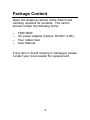
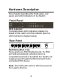
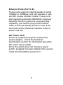
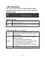
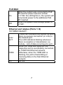
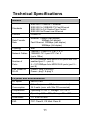
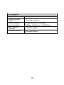
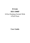
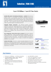
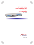
LevelOne FSW-0809 4+4 PoE Fast Ethernet Switch User Manual v1.0 - 0706 Safety FCC Warning This equipment has been tested and found to comply with the regulations for a Class B digital device, pursuant to Part 15 of the FCC Rules. These limits are designed to provide reasonable protection against harmful interference when the equipment is operated in a commercial environment. This equipment generates, uses, and can radiate radio frequency energy and, if not installed and used in accordance with this user’s guide, may cause harmful interference to radio communications. Operation of this equipment in a residential area is likely to cause harmful interference, in which case the user will be required to correct the interference at his or her own expense. CE Mark Warning This is a Class B product. In a domestic environment, this product may cause radio interference, in which case the user may be required to take adequate measures. ii Table of Content INTRODUCTION ..............................................1 FEATURES.......................................................2 PACKAGE CONTENT .....................................3 HARDWARE DESCRIPTION...........................4 FRONT PANEL .................................................4 REAR PANEL ...................................................4 LED INDICATORS.............................................6 System Power............................................6 PoE status (Port 1 ~ Port 4) ......................6 PoE MAX ...................................................7 Ethernet port status (Ports 1~8) ................7 POE RULE........................................................8 INSTALLATION..............................................10 TECHNICAL SPECIFICATIONS....................11 iii Introduction The FSW-0809 Switch integrates 100Mbps Fast Ethernet and 10Mbps Ethernet network capabilities in a highly flexible package. And this switch’s Port-1 to Port-4 are Power over Ethernet (PoE) ports, and it will automatically detects the presence of IEEE 802.3af-compliant powered device (PD) and provides power through the Port-1 to Port-4. The switch provides up to 15.4 W for PoE port and can be used to WLAN access point, IP phone, video camera and other PD devices. The Switch will automatically detect the network appliance’s requirements, and the switch will supplies the required power current to each appliance. Purpose Power over Ethernet (PoE) integrates power and data onto one single cabling infrastructure, eliminating the need to have AC power available at all locations. PoE is already widely adopted in the market, saving up to 50% of overall installation costs by eliminating the need to install separate electrical wiring and power outlets. 1 Features 8 ×10/100Mbps Auto-negotiation Fast Ethernet RJ45 ports with 4-port PoE function (port-1 ~ port-4) Compliant with 802.3af specification Supports PoE power up to 15.4W for PoE port Supports PoE power up to 30W for all PoE ports Supports PoE Powered Device (PD) classification identify Each port supports auto MDI/MDIX, so there is no need to use cross-over cables or an up-link port Full/half duplex transfer mode for each port Wire speed reception and transmission Up to 1K unicast addresses entities per device, self-learning, and table aging 96KBytes packet buffer Supports IEEE 802.3x flow control for fullduplex mode ports Supports Back-pressure flow control for half-duplex mode ports 2 Package Content Open the shipping cartons of the Switch and carefully unpacks its contents. The carton should contain the following items: – – – – FSW-0809 AC power adapter (Output: DC48V, 0.8A) Four rubber feet User Manual If any item is found missing or damaged, please contact your local reseller for replacement. 3 Hardware Description This chapter describes the front panel, rear panel, and LED indicators of the Switch. Front Panel LED Indicator: Comprehensive LED indicators display the status of the switch and the network (see the LED Indicators chapter below). Rear Panel PoE Ports (Port 1~4): These ports are PoE Enabled ports, the PoE port will automatically activated when a compatible terminal is identified, the Switch will supply power through the Ethernet port to the connected PoE device. Note: The PoE ports will not offer the power to the Legacy devices. 4 Ethernet Ports (Port 5~8): These ports support network speeds of either 10Mbps or 100Mbps, and can operate in halfand full- duplex transfer modes. These ports also supports automatic MDI/MDIX crossover detection function gives true “plug and play” capability, just need to plug-in the network cable to the hub directly and don’t care if the end node is NIC (Network Interface Card) or switch and hub DC Power Jack: Power is supplied through an external DC power adapter. Check the technical specification section for information about the DC power input voltage. Since the switch does not include a power switch, plugging its power adapter into a power outlet will immediately power it on. 5 LED Indicators The front panel LEDs provides instant status feedback, and, helps monitor and troubleshoot when needed. System Power On Off When the Power LED lights on, the Switch is receiving power. When the Power turns off or the power cord : has improper connection. : PoE status (Port 1 ~ Port 4) Green Yellow Off When the PoE powered device (PD) was : connected and the port supplies power successfully. When the PoE port have the following failure happens: PoE power circuit shortage : Power over current: over the power current of PD’s classification Out of PoE voltage of 44 ~ 57 VDC output : No PoE powered device (PD) connected. 6 PoE MAX On Off When the system was connected to PoE PD and the power resource remain : <=7.5W, the LED lights on, the system will not provide power to the additional PoE PD inserted. When the system have enough power of : >7.5W. Ethernet port status (Ports 1~8) 10/100M Link/ACT: Link/ ACT 100M Off These LED indicators are lighted up when there is a secure connection (or Link) to the desired port. : The LED indicators blinking whenever there is reception or transmission (i.e. Activity - Act) of data occurring at a port. When the 100M LED lights on, the respective port is successfully connected to 100M Fast Ethernet network. : Otherwise, when the 100M LED is blinking, the port is transmitting or receiving data on the Fast Ethernet network. : No link. 7 PoE Rule PoE Max: this function will help to protect the PoE Switch and to stabilize the power transmitting to the powered device (PD). If the system power remain <= 7.5 watt, the PoE MAX LED will light on and the system will not provide power to the additional PoE PD to protect the PoE Switch itself and to stabilize the power transmitting to the former PoE PD plugged in the Switch. For example: When there are PoE PD were connected to the PoE Switch and the total power consumption spends 25 watt, at this time the system remain 5 watt for buffer and the PoE MAX LED will light up. Once there is another PoE PD inserted, the system will not provide power to the additional PoE PD. 8 Priority: this function will help to protect the system when the system power was over loaded, the system will disable PoE function of the lower priority PoE port to maintain the power budget to the PoE port which is in high priority. The total power resource of the system is 30 watt sharing to the 4 PoE ports (maximum power for per port is 15.4 watt), when the PoE PD shared the power resource for over 30 watt, the system will automatically arrange the priority of these ports, the low port number will have the higher priority than the high port number, Port 1 > Port 2 > Port 3 > Port 4. For example: In this PoE Switch, Port 2 is using power with 7 watt, Port 3 is using power with 15.4 watt, these two ports are totally using 22.4 watt power, when there is an additional PoE PD inserted to Port 1 with 15.4 watt, that means the system power resource was over current, then the priority function will activate, the priority will set to the lowest port number then to highest port number, so Port 1 will have the 15.4 watt power, Port 2 will have 7 watt power, and the system will cut off the power transmitting to the Port 3 due to over current. 9 Installation The setup of the Switch can be performed using the following steps: 1. The surface must support at least 1.5 Kg for the Switch. 2. The power outlet should be within 1.82 meters (6 feet) of the Switch. 3. Visually inspect the DC power jack and make sure that it is fully secured to the power adapter. 4. Make sure that there is proper heat dissipation from and adequate ventilation around the Switch. Do not place heavy objects on the Switch. Connecting Network Cable The Switch supports 10Mbps Ethernet or 100Mbps Fast Ethernet and it runs both in half and full duplex mode using two pair of Category 5 cable. These RJ45 ports are Auto-MDI type port. The Switch can auto transform to MDI-II or MDI-X type, so you can just make an easy connection that without worrying if you are using a standard or crossover RJ45 cable. 10 Technical Specifications General Standards IEEE 802.3 10BASE-T Ethernet IEEE 802.3u 100BASE-TX Fast Ethernet IEEE 802.3x Full Duplex Flow Control IEEE 802.3af Power over Ethernet Protocol CSMA/CD Data Transfer Rate Ethernet: 10Mbps (half duplex) 20Mbps (full-duplex) Fast Ethernet: 100Mbps (half duplex) 200Mbps (full-duplex) Topology Star Network Cables 10BASET: 2-pair UTP Cat. 3, 4, 5 100BASE-TX: 2-pair UTP Cat. 5 (up to 100m) Number of Ports 4 × 10/100Mbps Auto-MDIX RJ45 ports with PoE enabled (port 1 ~ port 4) 4 × 10/100Mbps Auto-MDIX RJ45 ports (port 5 ~ port 8) PoE Power on RJ-45 Power+: ping 3 & ping 6 Power-: ping 1 & ping 2 Physical and Environmental DC inputs 48VDC/0.8A Power Consumption 6.3 watts. (max. no PD device connected) 36.3 watts (max. with 30w PD connected) Temperature Operating: 0°~40° C, Storage: -10°~70° C Humidity Operating: 10% ~ 90%, Storage: 5% ~ 90% Dimensions 171 x 98 x 29 mm EMI: FCC Class B, CE Mark Class B 11 Performance RAM Buffer: 96K bytes per device Filtering Address Table: 1K entries per device Packet Filtering / Forwarding Rate: 10Mbps Ethernet: 14,880/pps 100Mbps Fast Ethernet: 148,800/pps MAC Address Learning: Automatic update Transmits Method: Store-and-forward 12