1
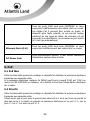
ITALIANO
Questo prodotto è coperto da garanzia Atlantis Land della durata di 2 anni. Per
maggiori dettagli in merito o per accedere alla documentazione completa in Italiano
fare riferimento al sito www.atlantis-land.com.
ENGLISH
This product is covered by Atlantis Land 2 years warranty. For more detailed
informations please refer to the web site www.atlantis-land.com.
For more detailed instructions on configuring and using this device, please refer to the
online manual.
FRANCAIS
Ce produit est couvert par une garantie Atlantis Land de 2 ans. Pour des informations
plus détaillées, référez-vous svp au site Web www.atlantis-land.com.
DEUTSCH
Dieses Produkt ist durch die Atlantis Land 2 Jahre Garantie gedeckt. Für weitere
Informationen, beziehen Sie sich bitte auf Web Site www.atlantis-land.com.
ESPAÑOL
Este producto esta cubierto por Atlantis Land con una garantía de 2 años. Para mayor
información diríjase a nuestro sitio Web www.atlantis-land.com.
ITALIANO
1. Panoramica Generale .......................................................................................... 8
1.1 Tecnologia Fast Ethernet ............................................................................. 8
1.2 Tecnologia Switching .................................................................................. 8
1.3 Power over Ethernet (PoE) .......................................................................... 9
2. Caratteristiche .................................................................................................... 9
3. Installazione .....................................................................................................11
3.1 Contenuto della Confezione ........................................................................11
3.2 Setup…………… ..........................................................................................11
3.3 Schema Applicativo ....................................................................................12
3.4 Installazione Desktop .................................................................................12
3.5 Collegamento cavo LAN..............................................................................13
4. Componenti Esterni ...........................................................................................13
4.1 Pannello Frontale .......................................................................................13
4.2 Pannello Posteriore ....................................................................................15
5. Avvertenze per alimentazione PoE ......................................................................16
5.1 PoE Max…………. ........................................................................................16
5.2 Priorità………. .............................................................................................17
6. Supporto...........................................................................................................18
ENGLISH
1. Introduction ......................................................................................................21
1.1 Fast Ethernet Technology ...........................................................................21
1.2 Switching Technology ................................................................................22
1.3 Power over Ethernet (PoE) .........................................................................22
2. Features ...........................................................................................................22
3. Unpacking and Setup.........................................................................................23
3.1 Package Contents ......................................................................................23
3.2 Installation… .............................................................................................23
3.3 Network Scheme........................................................................................24
3.4 Desktop Installation ...................................................................................24
3.5 Connecting Network Cable..........................................................................24
4. External Components.........................................................................................25
4.1 Front Panel................................................................................................25
3
4.2 Rear Pane…...............................................................................................27
5. PoE Rules .........................................................................................................28
5.1 PoE Max………............................................................................................28
5.2 Priority……….. ............................................................................................28
6. Support ............................................................................................................29
FRANCAIS
1. Introduction ......................................................................................................32
1.1 Technologie Fast Ethernet ..........................................................................32
1.2 Technologie Switching................................................................................32
1.3 Power over Ethernet (PoE) .........................................................................32
2. Principales caractéristiques ................................................................................33
3. Installation........................................................................................................34
3.1 Contenu de la boîte....................................................................................34
3.2 Setup……….. ..............................................................................................34
3.3 Example de Réseaux ..................................................................................35
3.4 Installation en Desktop ..............................................................................35
3.5 Connexion au reseau .................................................................................35
4. Panneaux Avant Et Arriere .................................................................................36
4.1 Panneau Avant ..........................................................................................36
4.2 Panneau Arrière .........................................................................................37
5. PoE ..................................................................................................................38
5.1 PoE Max…….. ............................................................................................38
5.2 Priorité…………… ........................................................................................38
6. Support ............................................................................................................39
APPENDIX A: Technical Specifications.....................................................................40
A02-F8PoE(v1.2)_GX01 (v1.0 Mar 2009)
4
AVVERTENZE
Abbiamo fatto di tutto al fine di evitare che nel testo, nelle immagini e nelle tabelle
presenti in questo manuale, nel software e nell'hardware fossero presenti degli errori.
Tuttavia, non possiamo garantire che non siano presenti errori e/o omissioni. Infine,
non possiamo essere ritenuti responsabili per qualsiasi perdita, danno o
incomprensione compiuti direttamente o indirettamente, come risulta dall'utilizzo del
manuale, software e/o hardware.
Il contenuto di questo manuale è fornito esclusivamente per uso informale, è soggetto
a cambiamenti senza preavviso (a tal fine si invita a consultare il sito
www.atlantisland.it o www.atlantis-land.com per reperirne gli aggiornamenti) e non
deve essere interpretato come un impegno da parte di Atlantis Land
che non si
assume responsabilità per qualsiasi errore o inesattezza che possa apparire in questo
manuale. Nessuna parte di questa pubblicazione può essere riprodotta o trasmessa in
altra forma o con qualsiasi mezzo, elettronicamente o meccanicamente, comprese
fotocopie, riproduzioni, o registrazioni in un sistema di salvataggio, oppure tradotti in
altra lingua e in altra forma senza un espresso permesso scritto da parte di Atlantis
Land. Tutti i nomi di produttori e dei prodotti e qualsiasi marchio, registrato o meno,
menzionati in questo manuale sono usati al solo scopo identificativo e rimangono
proprietà esclusiva dei loro rispettivi proprietari.
Restrizioni di responsabilità CE/EMC
Il prodotto descritto in questa guida è stato progettato, prodotto e approvato in
conformità alle regole EMC ed è stato certificato per non avere limitazioni EMC.
Se il prodotto fosse utilizzato con un PC non certificato, il produttore non garantisce il
rispetto dei limiti EMC. Il prodotto descritto è stato costruito, prodotto e certificato in
modo che i valori misurati rientrino nelle limitazioni EMC. In pratica, ed in particolari
circostanze, potrebbe essere possibile che detti limiti possano essere superati se
utilizzato con apparecchiature non prodotte nel rispetto della certificazione EMC. Può
anche essere possibile, in alcuni casi, che i picchi di valore siano al di fuori delle
tolleranze. In questo caso l’utilizzatore è responsabile della “compliance” con i limiti
EMC. Il Produttore non è da ritenersi responsabile nel caso il prodotto sia utilizzato al
di fuori delle limitazioni EMC.
5
Dichiarazione di Conformità
Con la presente Sidin SpA dichiara che questo apparato (A02-F8POE) soddisfa tutti i
requisiti applicabili alla tipologia del prodotto e richiesti dalla regolamentazione delle
telecomunicazioni secondo direttiva 2004/108/CE (compatibilità elettromagnetica) e
2006/95/CE (sicurezza elettrica) tramite l’utilizzo delle norme pubblicate nella gazzetta
ufficiale della comunità Europea. La dichiarazione di conformità nella sua forma
completa è disponibile presso il sito www.atlantis-land.com (alla pagina del prodotto) o
può essere richiesta a [email protected].
Importanti informazioni per il corretto riciclaggio/smaltimento
di questa apparecchiatura
Le informazioni riportate sono redatte Ai sensi dell’art. 13 del Decreto Legislativo 25
luglio 2005, n. 151"Attuazione delle Direttive 2002/95/CE, 2002/96/CE e 2003/108/CE,
relative alla riduzione dell'uso di sostanze pericolose nelle apparecchiature elettriche ed
elettroniche, nonché allo smaltimento dei rifiuti".
Il simbolo qui sotto indicato, riportato sull'apparecchiatura elettronica e/o sulla
confezione, indica che questa apparecchiatura elettronica non potrà essere smaltita
come un rifiuto qualunque ma dovrà essere oggetto di raccolta separata.
Infatti i rifiuti di apparecchiatura elettroniche ed elettroniche devono essere sottoposti
ad uno specifico trattamento, indispensabile per evitare la dispersione degli inquinanti
contenuti all''interno delle apparecchiature stesse, a tutela dell'ambiente e della salute
umana. Inoltre sarà possibile riutilizzare/riciclare parte dei materiali di cui i rifiuti di
apparecchiature elettriche ed elettroniche sono composti, riducendo così l'utilizzo di
risorse naturali nonché la quantità di rifiuti da smaltire.
La raccolta differenziata della presente apparecchiatura giunta a fine vita e'
organizzata e gestita dal produttore. L’utente che vorrà disfarsi della presente
apparecchiatura dovrà quindi contattare il produttore e seguire il sistema che questo
6
ha adottato per consentire la raccolta separata dell'apparecchiatura giunta a fine vita.
Si tenga presente che l'abbandono ed il deposito incontrollato di rifiuti sono puniti con
sanzioni amministrative previste dalla norma vigente.
Il suo contributo nella raccolta differenziata dei rifiuti di apparecchiature elettriche ed
elettroniche è essenziale per il raggiungimento di tutela della salute umana connessi al
corretto smaltimento e recupero delle apparecchiature stesse. 7
La ringraziamo per aver scelto un apparato Atlantis Land. Si consiglia la lettura di
questo documento al fine di un corretto utilizzo del prodotto.
1. Panoramica Generale
Questo capitolo descrive le caratteristiche proprie dello Switch e fornisce alcune
informazioni di carattere generale sulla tecnologia di switch Ethernet/Fast Ethernet.
1.1 Tecnologia Fast Ethernet
Il continuo aumento di importanza della LAN e l’incremento della complessità delle
applicazioni che girano sui normali PC ha portato alla necessità di avere strutture che
fornissero delle performance sempre crescenti. Un notevole numero di tecnologie
diverse per LAN ad alta velocità ha visto la luce proprio per rispondere a queste
esigenze. La soluzione che si è imposta (la 100BASE-T) risponde a queste rinnovate
esigenze pur avendo un approccio non distruttivo con l’installato.
Nelle specifiche IEEE 802.3 LAN sono contenute tutte le caratteristiche del 100Mbs
Fast Ethernet. Questa è un’estensione del precedente standard a 10Mbs cui aggiunge
la capacità di trasmissione dieci volte maggiore, pur mantenendo il protocollo
CSMA/CD. Questo consente agli apparati conformi alla Fast Ethernet di essere utilizzati
anche in modalità Ethernet, consentendo un riutilizzo di apparati e una migrazione
graduale alla nuova tecnologia.
1.2 Tecnologia Switching
Lo switching è una strada che rende possibile da un lato l’aumento della capacità
(numero di utenti collegati) di una rete e dall’altra la diminuzione del carico
suddividendo la LAN in diversi segmenti. Solo i segmenti opportuni sono interessati al
contrario dell’hub che replica il traffico su tutti i segmenti.
Lo switch attua una sorta di bridge selettivo tra segmenti individuali. Lo switch infatti,
senza interferire con altri segmenti, automaticamente instrada il traffico da un
segmento ad un altro. In questa maniera la capacità della LAN cresce notevolmente,
pur non dovendone cambiare l’hardware presente.
La tecnologia Switching LAN è un deciso miglioramento rispetto alla precedente
generazione dei network bridges caratterizzati da un’alta latenza. Questo problema
può essere risolto anche facendo uso di Router che segmentano la LAN ma il costo di
questa tecnologia notevolmente superiore unito alla necessità di un continuo controllo
8
rende questo approccio quasi impraticabile. Oggi lo switch rappresenta la soluzione
ideale per risolvere i problemi di congestione nella maggior parte delle LAN.
1.3 Power over Ethernet (PoE)
Power over Ethernet (PoE) permette di integrare il trasporto dati ed alimentazione su
un medesimo cavo LAN, eliminando cosi la necessità di cablaggio dell’infrastruttura
elettrica ove sia necessario creare un punto di accesso alla rete LAN.
Grazie a questa integrazione (è richiesto un cavo cat. 5/5e a 4 coppie) , sarà quindi
possibile alimentare direttamente dispositivi PoE quali telefoni IP, Access Point ed IP
Camera, riducendo in maniera importante l’ingombro ed il tempo di installazione del
dispositivo.
La tecnologia PoE, attualmente adottata da una larga parte di soluzioni presenti sul
mercato, permette una riduzione dei costi di installazione di oltre il 50%, eliminando la
necessità di stesura di cablaggio elettrico e relative prese di alimentazione.
E’ importante tenere conto che la tecnologia PoE fa riferimento alle limitazioni fisiche e
strutturali dello standard Ethernet (lunghezza di collegamento punto-punto fino a
100m).
Sul mercato sono presenti differenti soluzioni PoE in grado di
fornire in uscita alimentazioni di tipologia differente.
Il prodotto in oggetto fa riferimento ad alimentazione PoE
secondo standard IEEE 802.3af.
(Per ogni eventuale approfondimento, si consiglia di fare
riferimento alla documentazione ufficiale reperibile all’indirizzo
http://www.ieee802.org/3/af/)
2. Caratteristiche
Lo Switch è stato disegnato per essere facilmente installato ed offrire alte performance
in un ambienti professionali dove sia richiesta l’alimentazione tramite PoE di molteplici
dispositivi. Vediamo le caratteristiche chiave dello Switch:
•
•
8 porte 10/100Mbps Fast Ethernet con Auto-negoziazione (connettore
RJ45) di cui 4 con funzionalità PoE
Conforme alle specifiche IEEE802.3af
9
•
•
•
•
•
•
•
•
•
•
Supporto alimentazione PoE fino a 15.4W per singola porta PoE
Supporto alimentazione PoE fino a 30W suddiviso tra le porte PoE
Supporto classificazione periferiche PoE alimentate (PD)
Supporto Auto MDI/MDIX per ogni singola porta
Modalità di trasferimento Full/half-duplex per ogni singola porta
Ricezione e trasmissione Wire speed
Fino a 1K MAC Address per dispositivo, self-learning, and table aging
96KBytes packet buffer
Controllo di flusso IEEE 802.3x in modalità full-duplex
Controllo di flusso Back-pressure in modalità half-duplex
10
3. Installazione
Questo capitolo fornisce informazioni per l’installazione e la configurazione dello
Switch. Per evitare possibili cause di danneggiamento è opportuno leggere
attentamente l’intero paragrafo prima di partire.
3.1 Contenuto della Confezione
Una volta aperta la confezione in cartone dovrebbero essere presenti:
•
•
•
•
•
•
1
1
4
1
1
1
x
x
x
x
x
x
NetMaster F8PoE
Alimentatore esterno
Supporti in gomma per il montaggio desktop
Guida Utente (Italiano, Inglese e Francese)
Tagliando di Garanzia (Italiano)
WEEE Disclaimer
Qualora mancasse uno qualsiasi di questi componenti è opportuno rivolgersi
immediatamente al rivenditore.
3.2 Setup
La fase di setup dello Switch prevede i seguenti steps:
•
•
•
•
La superficie di installazione deve supportare almeno 1,5 Kg per
permettere l’installazione del dispositivo.
Assicurarsi che la presa del cavo di alimentazione sia collegata
propriamente al connettore AC posto sul pannello posteriore
dell’apparecchio.
Accertarsi che sia posto in un ambiente con un’adeguata ventilazione, non
esposto a raggi solari, in un ambiente privo di vibrazioni e in assenza di
forti campi elettromagnetici (tipicamente creati da motori elettrici).
Controllare inoltre le condizioni di temperatura ed umidità (facendo
riferimento alla tabella Caratteristiche Fisiche ed Ambientali).
11
3.3 Schema Applicativo
3.4 Installazione Desktop
Prima di posizionare l’apparato sulla scrivania, è necessario attaccare i supporti in
gomma forniti per il montaggio desktop alle scanalature poste nella parte inferiore del
prodotto; quindi posizionare NetMaster F8PoE sulla superficie operativa.
12
3.5 Collegamento cavo LAN
Il prodotto dispone di 8 porte Fast Ethernet 10/100Mbps di cui 4 con supporto PoE;
quest’ultime si attiveranno automaticamente al collegamento di una periferica con
supporto PoE, fornendo alimentazione tramite cavo di rete all’apparecchiatura
collegata sulla specifica porta.
Per salvaguardare i dispositivi ad esso collegati, se il dispositivo rilevato non verrà
ritenuto compatibile con lo standard IEEE 802.3af, lo Switch non fornirà alcuna
alimentazione sulla porta; questa funzionalità permette il collegamento, senza rischio
alcuno, di dispositivi di varia natura alle porte dello Switch.
Il prodotto è in grado di lavorare secondo gli standard Ethernet (10Mbps) e Fast
Ethernet (100Mbps) in modalità Half/Full-Duplex utilizzando cavi a 2 coppie di
categoria 5.
Tutte le porte, con connettore RJ45, supportano la tecnologia Auto MDI/MDI-X,
permettendo alla switch di adattarsi al cablaggio (dritto od incrociato) installato.
4. Componenti Esterni
4.1 Pannello Frontale
La figura sottostante riporta il pannello frontale del dispositivo.
13
Gli indicatori LED posti sulla parte frontale permettono una diagnostica immediata
dello stato di funzionamento di ogni singolo link.
LED
SIGNIFICATO
On: Quando accesso verde fisso, indica la
corretta alimentazione del dispositivo.
PWR (Power Indicator)
PoE Status
Off: Se spento, indica una non corretta
alimentazione del dispositivo. Si consiglia di
verificare lo stato dell’alimentatore esterno e il
corretto collegamento dello stesso allo Switch.
Verde: Quando una periferica PoE (PD) è
collegata alla porta ed alimentata correttamente.
Giallo: Indica una delle seguenti anomalie:
•
Corto circuito sull’alimentazione PoE
•
Potenza richiesta superiore a quella
erogabile dal dispositivo
•
Oltre finestra di tolleranza per il
voltaggio PoE in uscita (44 ~ 57
VDC)
Off: Nessuna periferica PoE (PD) collegata.
PoE MAX
On: Quando la potenza totale erogabile da parte
dello Switch per i dispositivi PoE risulti <=7.5W,
questo LED sarà accesso, indicando che lo
stesso non è in grado di fornire alimentazione
PoE ai nuovi dispositivi (PD) che verranno ad
esso collegati.
Off: Quando la potenza totale erogabile sulle
porte PoE è superiore ai 7.5W.
10/100 Link/ACT
Link/ACT: In caso di connessioni a 10M, indica
lo stato di funzionamento del link.
14
100M: Accesso, indica il corretto collegamento
della rispettiva porta ad un dispositivo Fast
Ethernet. Lampeggiante nel caso in cui sia attivo
un trasferimento di dati sul link Ethernet.
Off: Nessun collegamento.
4.2 Pannello Posteriore
PORTE
PoE Ports (1-4)
SIGNIFICATO
Queste sono porte con funzionalità PoE; il supporto
PoE verrà automaticamente attivato al momento della
rilevazione di un dispositivo compatibile. Da questo
momento il dispositivo ad essa collegato verrà
alimentato attraverso la porta Ethernet.
Nel caso in cui il dispositivo collegato alla porta non
venga correttamente identificato e/o non supporti
questa tipologia di alimentazione, la porta dello Switch
non fornirà alimentazione PoE alla periferica, onde
evitare di danneggiare l’apparato collegato; questa
funzionalità permette all’utenza di utilizzare in tutta
sicurezza qualsiasi tipo di dispositivo Ethernet, senza
alcun rischio di danneggiamento.
Le porte supportano velocità di trasferimento dati fino
10 e 100 Mbps, in modalità half-duplex e full-duplex,
nonché la modalità Auto MDI/MDI-X che permette
15
Ethernet Ports (5-8)
DC Power Jack
l’utilizzo indistinto di qualsiasi tipo di cavo (dritto o
incrociato).
Le porte supportano velocità di trasferimento dati 10 e
100 Mbps, in modalità half-duplex e full-duplex,
nonché la modalità Auto MDI/MDI-X che permette
l’utilizzo indistinto di qualsiasi tipo di cavo (dritto o
incrociato).
L’alimentazione dell’apparato è fornita tramite un
alimentatore esterno.
Consultare le specifiche tecniche per Informazioni in
merito alle caratteristiche dello stesso.
Il prodotto non dispone di pulsante di accensione, per
cui verrà automaticamente avviato al collegamento
dell’alimentazione.
Tutte le porte sono con autopolarità, pertanto funzioneranno
(aggiustando la polarità) indipendentemente dal cavo utilizzato
(sia questo dritto o incrociato). Potrete collegare ogni porte
indipendentemente dal cavo sia ad una scheda di rete che ad
un hub/switch.
5. Avvertenze per alimentazione PoE
5.1 PoE Max
Questa funzionalità permette di proteggere lo switch da sovraccarichi
sull’alimentazione PoE e garantisce la fornitura di un alimentazione stabile alle
periferiche (PD) collegate alle porte PoE dello stesso (1-4).
Se la potenza totale istantanea erogabile dallo Switch è uguale od inferiore a 7.5W,il
led PoE Max si accenderà ed il prodotto non fornirà alimentazione alle periferiche PoE
(PD) addizionali che verranno collegate successivamente, al fine di proteggere il
prodotto e garantire un’alimentazione stabile alle periferiche ad precedentemente
collegate.
Ad esempio, se colleghiamo allo Switch alcune periferiche PoE (PD) per un
assorbimento totale di 25W, rimarranno disponibili solo 5W per cui il led PoE Max si
16
accenderà segnalando la condizione. Al collegamento di un ulteriore periferica PoE,
quest’ultima non verrà alimentata, al fine di rispettare quando detto sopra.
5.2 Priorità
Questa funzionalità permette di proteggere lo switch da sovraccarichi
sull’alimentazione PoE e garantisce la fornitura di un alimentazione stabile alle
periferiche (PD) collegate alle porte PoE dello stesso (1-4).
Nello specifico, in caso di sovraccarico, lo Switch interromperà l’alimentazione PoE alla
porta con priorità inferiore al fine di garantire il corretto apporto energetico alla/e
porte con priorità maggiore.
Il limite massimo di potenza erogabile dal prodotto è di 30W, suddiviso sulle 4 porte
PoE (per un massimo di 15.4W per porta); nel caso in cui l’assorbimento richiesto dalle
periferiche PoE (PD) collegate allo Switch sia superiore al limite totale (30W), il
sistema predisporrà automaticamente la priorità sulle porte PoE alimentate (la priorità
delle porte è indirettamente proporzionale al numero identificativo, eg: Port1 > Port2
> Port3 > Port4).
Ad esempio, si ponga il caso in cui la porta 2 alimenti una PD con assorbimento di 7W
e la porta 3 richieda 15.4W; in questo caso, l’assorbimento totale istantaneo è pari a
22.4W (non sufficiente per soddisfare la condizione PoE Max) e si ponga di voler
aggiungere un ulteriore periferica PD sulla porta 1 con assorbimento di 15.4W.
Al collegamento della periferica sulla porta 3, il dispositivo soddisferà la condizione di
sovraccarico (37.8W), la quale andrà ad attivare la funzionalità di prioritizzazione delle
porte Power over Ethernet; in accordo a quanto detto sopra, la priorità verrà
assegnata in maniera inversa al numero di porta (porta 1 High, porta 4 Low) e quindi
verrà garantita la corretta alimentazione sulle porte 1 (15.4W) e 2 (7W),
interrompendo l’alimentazione sulla porta 3 al fine di cessare la condizione di
sovraccarico.
17
6. Supporto
Per qualunque altro problema o dubbio sul funzionamento del prodotto, è possibile
contattare il servizio di assistenza tecnica Atlantis Land tramite l’apertura di un ticket
on-line sul portale http://www.atlantis-land.com/ita/supporto.php.
Nel caso non fosse possibile l’accesso al portale di supporto, è altresì possibile
richiedere assistenza telefonica al numero 02/00632345.
Per esporre eventuali richieste di supporto prevendita o richieste di contatto , vi
invitiamo ad utilizzare gli indirizzi mail [email protected] oppure
[email protected].
Atlantis Land
Via Pelizza da Volpedo, 59
20092 Cinisello Balsamo (MI) - Italy
Tel: +39. 02.00.632.300
Fax: +39. 02.66.016.666
Website: http://www.atlantis-land.com
Email: [email protected]
18
Copyright Statement
No part of this publication may be reproduced, stored in a retrieval system, or
transmitted in any form or by any means, whether electronic, mechanical,
photocopying, recording or otherwise without the prior writing of the publisher.
Windows™ 98SE/2000/ME/XP/VISTA are trademarks of Microsoft® Corp. Pentium is
trademark of Intel. All copyright reserved.
The Atlantis Land logo is a registered trademark of Atlantis Land. All other names
mentioned mat be trademarks or registered trademarks of their respective owners.
Subject to change without notice. No liability for technical errors and/or omissions.
CE Mark Warning
In a domestic environment, this product may cause radio interference, in which case
the user may be required to take adequate measures.
CE/EMC Restriction of Liability
The product described in this handbook was designed, produced and approved
according to the EMC-regulations and is certified to be within EMC limitations.
If the product is used in an uncertified PC, the manufacturer undertakes no warranty
in respect to the EMC limits. The described product in this handbook was constructed,
produced and certified so that the measured values are within EMC limitations. In
practice and under special circumstances, it may be possible, that the product may be
outside of the given limits if it is used in a PC that is not produced under EMC
certification. It is also possible in certain cases and under special circumstances,
which the given EMC peak values will become out of tolerance. In these cases, the
user himself is responsible for compliance with the EMC limits.
19
Declaration of Conformity
Hereby, Sidin SpA, declares that this product (A02-F8POE) is in compliance to all
relevant essential requirements of the Electromagnetic Compatibility Directive
(2004/108/CE) and Safety (2006/95/CE). CE Declaration is available on the web site
www.atlantis-land.com.
Important information for the correct recycle/treatment
procedures of this equipment
The mentioned information are reported herewith in compliance with directive
2002/95/CE, 2002/96/CE and 2003/108/CE which requires a separate collection
system and specific treatment and disposal procedures for the waste of electric and
electronic equipments.
The crossed-out wheeled bin symbol printed on the unit label or unit packaging
indicates that this equipment must not be disposed of as unsorted municipal waste but
it should be collected separately.
The waste of electric and electronic equipment must be treated separately, in order to
ensure that hazardous materials contained inside the equipment are not buried
thereby providing potential future problems for the environment and human health.
Moreover, it will be possible to reuse and recycle some parts of the waste of electric
and electronic equipment, contributing to reduce the quantities of waste to be
disposed of and the depletion of natural resources.
As user of this equipment, you are responsible to contact the producer to know the
correct procedure in the separate collection system for the waste of electric and
electronic equipments.
Your rôle in participating to the separate collection of waste of electric and electronic
equipment is essential to ensure that environmental protection and human health
objectives connected to a responsible treatment and recycling activities are achieved.
20
Congratulations on your purchase of the 8-Port 10/100Mbps Fast Ethernet Switch with
4-Port PoE. This Switch integrates 100Mbps Fast Ethernet and 10Mbps Ethernet
network capabilities in a highly flexible package. And this switch’s Port-1 to Port-4 are
Power over Ethernet (PoE) ports, and it will automatically detects the presence of IEEE
802.3af-compliant powered device (PD) and provides power through the Port-1 to
Port-4. The switch provides up to 15.4 W for PoE port and can be used to WLAN
access point, IP phone, video camera and other PD devices. The Switch will
automatically detect the network appliance’s requirements, and the switch will supplies
the required power current to each appliance.
In this guide, the term “Switch” (first letter upper case) refers
to your 8-Port 10/100Mbps Fast Ethernet Switch with 4-Port
PoE and “switch” (first letter lower case) refers to other
Ethernet switches.
1. Introduction
This chapter describes the features of the Switch and some background information
about Ethernet/Fast Ethernet switching technology.
1.1 Fast Ethernet Technology
The growing importance of LANs and the increasing complexity of desktop computing
applications are fueling the need for high performance networks. A number of highspeed LAN technologies have been proposed to provide greater bandwidth and
improve client/server response times. Among them, 100BASE-T (Fast Ethernet)
provides a non-disruptive, smooth evolution from the current 10BASE-T technology.
The non-disruptive and smooth evolution nature, and the dominating potential market
base, virtually guarantee cost effective and high performance Fast Ethernet solutions
in the years to come.
100Mbps Fast Ethernet is a new standard specified by the IEEE 802.3 LAN committee.
It is an extension of the 10Mbps Ethernet standard with the ability to transmit and
receive data at 100Mbps, while maintaining the CSMA/CD Ethernet protocol. Since the
100Mbps Fast Ethernet is compatible with all other 10Mbps Ethernet environments, it
provides a straightforward upgrade and takes advantage of the existing investment in
hardware, software, and personnel training.
21
1.2 Switching Technology
Another key development pushing the limits of Ethernet technology is in the field of
switching technology. A switch bridges Ethernet packets at the MAC address level of
the Ethernet protocol transmitting among connected Ethernet or fast Ethernet LAN
segments.
Switching is a cost-effective way of increasing the total network capacity available to
users on a local area network. A switch increases capacity and decreases network
loading by making it possible for a local area network to be divided into different
segments which don’t compete with each other for network transmission capacity,
giving a decreased load on each.
The switch acts as a high-speed selective bridge between the individual segments.
Traffic that needs to go from one segment to another is automatically forwarded by
the switch, without interfering with any other segments. This allows the total network
capacity to be multiplied, while still maintaining the same network cabling and adapter
cards.
Switching LAN technology is a marked improvement over the previous generation of
network bridges, which were characterized by higher latencies. Routers have also
been used to segment local area networks, but the cost of a router and the setup and
maintenance required make routers relatively impractical. Today’s switches are an
ideal solution to most kinds of local area network congestion problems.
1.3 Power over Ethernet (PoE)
Power over Ethernet (PoE) integrates power and data onto one single cabling
infrastructure, eliminating the need to have AC power available at all locations.
Power and Data is integrated onto the same cable, supporting category 5/5e up to 100
Meters, PoE will provide power to PoE compatible device, such as IP telephones,
wireless LAN access points and IP security cameras.
PoE is already widely adopted in the market, saving up to 50% of overall installation
costs by eliminating the need to install separate electrical wiring and power outlets.
2. Features
•
8 ×10/100Mbps Auto-negotiation Fast Ethernet RJ45 ports with 4-port PoE
function (port-1 ~ port-4)
22
•
•
•
•
•
•
•
•
•
•
•
Compliant with 802.3af specification
Supports PoE power up to 15.4W for PoE port
Supports PoE power up to 30W for all PoE ports
Supports PoE Powered Device (PD) classification identify
Each port supports auto MDI/MDIX, so there is no need to use cross-over
cables or an up-link port
Full/half duplex transfer mode for each port
Wire speed reception and transmission
Up to 1K unicast addresses entities per device, self-learning, and table
aging
96KBytes packet buffer
Supports IEEE 802.3x flow control for full-duplex mode ports
Supports Back-pressure flow control for half-duplex mode ports
3. Unpacking and Setup
This chapter provides unpacking and setup information for the Switch.
3.1 Package Contents
Unpack the package and check all the items carefully. If any item contained is
damaged or missing, please contact your local dealer as soon as possible. Also, keep
the box and packing materials in case you need to ship the unit in the future. The
package should contain the following items:
•
•
•
•
One NetMaster F8POE Switch
One external AC Power Supply
Rubber footpads for Desk-mount
One Quick Start Guide (English, Italian and French)
3.2 Installation
The setup of the Switch can be performed using the following steps:
•
•
The surface must support at least 1.5 Kg for the Switch.
The power outlet should be within 1.82 meters (6 feet) of the Switch.
23
•
•
Visually inspect the DC power jack and make sure that it is fully secured to
the power adapter.
Make sure that there is proper heat dissipation from and adequate
ventilation around the Switch. Do not place heavy objects on the Switch.
3.3 Network Scheme
3.4 Desktop Installation
When installing the Switch on a desktop or shelf, the rubber feet included with the
device must be first attached. Attach these cushioning feet on the bottom at each
corner of the device. Allow enough ventilation space between the device and the
objects around it.
3.5 Connecting Network Cable
The Switch support 8 10/100M Ethernet ports and Port 1 ~ port 4 are PoE Enabled
ports, these PoE port will automatically activated when a compatible terminal is
identified, the Switch will supply power through the Ethernet port to the connected
PoE powered device (PD).
24
For the Legacy devices that are not yet compatible, the PoE port will not offer the
power to this device. This feature allows users to freely and safely mix legacy and
Power over LAN compatible devices on their network.
The Switch supports 10Mbps Ethernet or 100Mbps Fast Ethernet and it runs both in
half and full duplex mode using two pair of Category 5 cable.
These RJ45 ports are Auto-MDI type port. The Switch can auto transform to MDI-II or
MDI-X type, so you can just make an easy connection that without worrying if you are
using a standard or crossover RJ45 cable.
4. External Components
4.1 Front Panel
The figure below shows the front panels of the switch.
Comprehensive LED indicators display the status of the switch and the network.
LED
PWR (Power Indicator)
MEANING
On: When the Power LED lights on, the Switch
is receiving power.
25
Off: When the Power turns off or the power
cord has improper connection.
PoE Status
Green: When the PoE powered device (PD) was
connected and the port supplies power
successfully.
Yellow: When the PoE port have the following
failure happens:
•
PoE power circuit shortage
•
Power over current: over the power
current of PD’s classification
•
Out of PoE voltage of 44 ~ 57 VDC
output
Off: No PoE powered device (PD) connected.
PoE MAX
On: When the system was connected to POE PD
and the power resource remain <=7.5W, the
LED lights on, the system will not provide power
to the additional POE PD inserted.
Off: When the system have enough power of
>7.5W.
10/100 Link/ACT
Link/ACT: When the 10M LED lights on, the
respective port is successfully connected to 10M
Ethernet network.
100M: When the 100M LED lights on, the
respective port is successfully connected to
100M Fast Ethernet network. Otherwise, when
the 100M LED is blinking, the port is
transmitting or receiving data on the Fast
Ethernet network.
Off: No Link.
26
4.2 Rear Panel
PORTS
PoE Ports (1-4)
Ethernet Ports (5-8)
MEANING
These ports are PoE Enabled ports, the PoE port will
automatically activated when a compatible terminal is
identified, the Switch will supply power through the
Ethernet port to the connected PoE device.
For the Legacy devices that are not yet compatible,
the PoE port will not offer the power to this device.
This feature allows users to freely and safely mix
legacy and Power over LAN compatible devices on
their network
These ports support network speeds of either 10Mbps
or 100Mbps, and can operate in half- and full- duplex
transfer modes. These ports also supports automatic
MDI/MDIX crossover detection function gives true
“plug and play” capability, just need to plug-in the
network cable to the hub directly and don’t care if the
end node is NIC (Network Interface Card) or switch
and hub.
27
DC Power Jack
Power is supplied through an external DC power
adapter. Check the technical specification section for
information about the DC power input voltage.
Since the switch does not include a power switch,
plugging its power adapter into a power outlet will
immediately power it on.
5. PoE Rules
5.1 PoE Max
This function will help to protect the POE Switch and to stabilize the power
transmitting to the powered device (PD).
If the system power remain <= 7.5 watt, the POE MAX LED will light on and the
system will not provide power to the additional POE PD to protect the POE Switch itself
and to stabilize the power transmitting to the former POE PD plugged in the Switch.
For example, when there are POE PD were connected to the POE Switch and the total
power consumption spends 25 watt, at this time the system remain 5 watt for buffer
and the POE MAX LED will light up. Once there is another POE PD inserted, the system
will not provide power to the additional POE PD.
5.2 Priority
This function will help to protect the system when the system power was over loaded,
the system will disable PoE function of the lower priority PoE port to maintain the
power budget to the PoE port which is in high priority.
The total power resource of the system is 30 watt sharing to the 4 POE ports
(maximum power for per port is 15.4 watt), when the POE PD shared the power
resource for over 30 watt, the system will automatically arrange the priority of these
ports, the low port number will have the higher priority than the high port number,
Port 1 > Port 2 > Port 3 > Port 4.
For example: In this POE Switch, Port 2 is using power with 7 watt, Port 3 is using
power with 15.4 watt, these two ports are totally using 22.4 watt power, when there is
an additional POE PD inserted to Port 1 with 15.4 watt, that means the system power
resource was over current, then the priority function will activate, the priority will set
to the lowest port number then to highest port number, so Port 1 will have the 15.4
28
watt power, Port 2 will have 7 watt power, and the system will cut off the power
transmitting to the Port 3 due to over current.
6. Support
For technical questions and support, please contact our help-desk by ticket on
http://www.atlantis-land.com/ita/supporto.php.
For generic information, please send an e-mail to [email protected].
For presales informations, please send an e-mail to [email protected].
Atlantis Land
Via Pelizza da Volpedo, 59
20092 Cinisello Balsamo (MI) - Italy
Tel: +39. 02.00.632.300
Fax: +39. 02.66.016.666
Website: http://www.atlantis-land.com
Email: [email protected]
29
Copyright
Copyright . 2002 est la propriété de cette société. Tous droits réservés. Sont interdites,
la reproduction, la transmission, la transcription, la mémorisation dans un système de
sauvegarde où la traduction dans une autre langue ou en langage informatique quels
qu’ils soient, de la présente publication, sous quelque forme que ce soit ou quel qu’en
soit le moyen, électronique, mécanique, magnétique, optique, chimique, manuel ou de
tout autre genre, sans avoir obtenu au préalable le consentement de notre entreprise.
Non-responsabilité
La présente entreprise n’admet pas de requêtes ni de garantie, explicites ou implicites,
au sujet du contenu et de manière spécifique exclu la possibilité de garantie,
commerciabilité ou adaptabilité pour des buts particuliers. Le logiciel décrit dans le
présent manuel est vendu ou concédé en licence “tel quel”. Si les programmes
devaient présenter des problèmes après l’achat, l’acquéreur (et non pas la présente
entreprise, son distributeur ou concessionnaire) est tenu de prendre en charge tous les
coûts de manutention ainsi que les coûts dus à des dommages accidentels ou des
conséquences dérivants d’un défaut du logiciel. La présente entreprise se réserve en
outre le droit de revoir le contenu de cette publication et d’y apporter des
modifications de temps en temps, sans obligation d’informer les utilisateurs de ces
changements. Nous avons fait tout notre possible afin d’éviter la présence d’erreurs
dans le texte, dans les images et dans les tableaux présents dans ce manuel, dans le
logiciel et le disque dur. Cependant, nous ne pouvons pas garantire l’absence totale
d’erreurs et/ou omissions et nous vous prions de nous les signaler. Enfin, nous ne
pouvons être retenus responsables pour quelque perte que ce soit, dommage ou
incompréhension avenus directement ou indirectement, suite à l’utilisation de notre
manuel logiciel et/ou disque dur.
Toutes les marques ou noms de produits mentionnés dans le présent manuel sont des
marques commerciales et/ou brevetées par leurs propriétaires respectifs.
Marquage CE
Cet appareil peut causer des interférences radio, dans ce cas nous vous invitons à
prendre les contre-mesures appropriées.
30
Déclaration de Conformité
Sidin SpA déclare que ce produit (A02-F8PoE) est conforme aux exigences de
protection de la Directive (2004/108/CE) du conseil de l’UE (sur le rapprochement des
lois des Etas membres en matière de compatibilité électromagnétique) et aussi à la
Directive (2006/95/CE). Il est possible de télécharger sur le site web (www.atlantisland.com) le document complet.
Information importante sur le recyclage et le traitement de cet
équipement
Les informations susmentionnées sont fournies ici en conformité avec la Directive
2002/96/CE et le Décret n° 2005-829 du 20 juillet 2005 relatif à la composition des
équipements électriques et électroniques et à l'élimination des déchets issus de ces
équipements qui prévoient des procédures de collecte sélective et de traitement et
d'élimination spécifiques aux déchets d'équipements électriques et électroniques. Pour
de plus amples informations, nous vous invitonsà consulter notre site Internet à
l'adresse suivante www.atlantis-land.com. Le symbole représentant une poubelle sur
roues barrée d'une croix, qui est imprimé sur l'étiquette ou l'emballage du produit,
indique que cet équipement ne doit pas être éliminé avec les déchets municipaux non
triés mais doit faire l'objet d'une collecte sélective. Les déchets d'équipements
électriques et électroniques doivent être traités séparément afin d'éviter que les
matières dangereuses contenues dans ces équipements ne soient enterrées, ce qui
pourrait occasionner des risques futurs pour l'environnement et la santé humaine. De
plus, certains éléments des déchets d'équipements électriques et électroniques
pourront être réutilisés et recyclés, ce qui contribuera à réduire les quantités de
déchets à éliminer et à limiter l'épuisement des ressources naturelles. Pour de plus
amples informations, nous vous invitonsà consulter notre site Internet à l'adresse
suivante www.atlantis-land.com. Votre participation à la collecte sélective des déchets
d'équipements électriques et électroniques est essentielle pour garantir que les
objectifs de protection de l'environnement et de la santé humaine seront atteints.
31
Ce guide permet de configurer le Switch 8 ports Fast Ethernet dont 4 PoE.
1. Introduction
Ce chapitre décrit les caractéristiques du Switch et fournit des informations générales
sur la technologie de switch Ethernet/Fast Ethernet.
1.1 Technologie Fast Ethernet
La norme IEEE 802.3 fixe les caractéristiques du Fast Ethernet 100 Mb/s, il s’agit d’une
extension du standard précédent Ethernet 10 Mb/s qui implémente une capacité de
transmission dix fois plus importante, tout en maintenant le protocole CSMA/CD. Cela
permet aux appareils Fast Ethernet d’être utilisable en mode Ethernet, permettant
donc une utilisation des appareils existants et une évolution graduelle vers la nouvelle
technologie.
1.2 Technologie Switching
Le switching est une solution qui permet d’une part l’augmentation des capacités
(nombre d’utilisateurs connectés) d’un réseau et d’autre part la diminution de la
charge en divisant le LAN en plusieurs segments. Seuls les segments appropriés sont
utilisés au contraire du hub qui répète le trafic sur tous les segments.
Le switch réalise une sorte de pont sélectif entre les segments individuels. Le switch
en effet, sans créer d’interférence avec les autres segments, dirige le trafic
automatiquement d’un segment à l’autre. La technologie Switching LAN est une
amélioration notable par rapport à la génération précédente de réseaux bridges
caractérisés par une plus grande lenteur. Ce problème peut aussi être résolu en
utilisant des Routeurs qui segmentent le LAN mais le coût de ces technologies est
nettement supérieur et la nécessité d’un contrôle constant rend cette solution quasiimpossible. Aujourd’hui le switch représente la solution idéale pour résoudre les
problèmes de congestion dans la plupart des LAN.
1.3 Power over Ethernet (PoE)
Le PoE (Power over Ethernet) permet de fournir à la fois le courant électrique (faible
voltage) et les données via un seul cable Ethernet (5/5e jusqu’à 100mt) un
périphérique réseaux comme par exemple une webcam, un téléphone VoIP ou un
32
point d’accès Wi-Fi. Les données et l’alimentation électrique passent dans le même
cable Ethernet, il n’y a plus qu’un cable à tirer par périphérique.
2. Principales caractéristiques
Voyons à présent, les caractéristiques principales du Switch :
•
•
•
•
•
•
•
•
•
•
•
•
8 x Ports réseaux Fast Ethernet 10/100 Mbps dont 4 PoE
Commutation MDI/MDIX pour chaque port
Modes full et half-duplex pour chaque port
Mode de transfert: Wire speed reception et transmission
LEDs individuelles d'activité pour chaque port
Contrôle de flux (IEEE 802.3x) [full-duplex]
Contrôle de flux Back pressure [half-duplex]
Apprentissage Automatique des addresses MAC
Le Switch est compatible avec IEEE802.3af et PoE Powered Device (PD)
Switch peux garantir jusqu’à 15.4W pour la port PoE
Le Switch peux garantir jusqu’à 30W pour tous les 4 PoE
96KBytes packet buffer
33
3. Installation
Ce chapitre fournit des informations pour l’installation et la configuration du Switch.
Pour éviter les problèmes, nous vous recommandons de lire avec attention ce chapitre
avant de commencer.
3.1 Contenu de la boîte
A l’ouverture de la boîte, vérifiez son contenu:
•
•
•
•
1
4
1
1
x
x
x
x
NetMaster F8PoE
Pieds adhésifs
Adapteur secteur
Guide Utilisateur (Francais, Italien et Anglais)
3.2 Setup
Déterminez l’emplacement du commutateur. Vous avez besoin d’une surface plane et
horizontale, par exemple sur un bureau.
Vérifiez que l’emplacement choisi:
•
•
•
•
Ne se trouve pas en plein soleil ni près d’un radiateur ou d’une bouche de
chauffage
N’est pas encombré (vous devez laisser au moins 12 cm dégagés de tous
les côtés)
Doit être bien ventilé (en particulier si vous installez le commutateur dans
une armoire)
Vous avez également besoin d’un câble Ethernet de Catégorie 5 muni de
connecteurs RJ-45 pour chacun des périphériques que vous voulez
connecter au commutateur.
34
3.3 Example de Réseaux
3.4 Installation en Desktop
Lorsque l’on installe le Switch sur une surface plane ou une étagère il est nécessaire
d’utiliser en premier lieu les pieds en caoutchouc (à attacher sur les 4 angles de la
base). Ceux-ci sont positionnés dans les 4 angles inférieurs du dispositif et ont pour
but d’amortir les chocs. S’assurer que la ventilation soit suffisante entre le Switch et
d’autres objets éventuellement placés autour.
3.5 Connexion au reseau
Tous les (1,2,3,4) ports RJ45 supportent le standard PoE. Si un dispositif PoE (PD) est
connecté, la port (PoE) va garantir l’alimetation (jusqu’à 15W). Si un dispositif pas
compatible avec le PoE (PD) est connecté le Switch n’envoi pas l’alimentation
électrique sur le cable.
Tous les ports RJ45 sont auto MDI/MDIX et donc supportent indifféremment des
cables droit ou croisé.
35
4. Panneaux Avant Et Arriere
4.1 Panneau Avant
LED
PWR (Power Indicator)
PoE Status
SIGNIFICATION
Allumée: Si la led est allumée, il indique une
alimentation correcte
Eteinte: Si n’est pas allumée il faut verifier l’
alimentation.
Vert: Si allumée il indique une alimentation d’un
dispositif PoE (PD) correcte.
Jaune: il y a un problem sur la port:
•
La puissance sur les ports PoE est
proche à al puissance max
•
Power over current: Un dispositif est
en train de demander plus courant
que le limit prevu
•
Le voltage est anormal (<44V ou
>57V)
36
Off: Il n’y a pas de dispositif PoE (PD)
Allumée: sur le Switch sont connectés PD
(dispositif PoE) et la puissance restante est
<=7.5W. Dans ce cas le Switch ne va pas
donner de l’alimentation électrique.
PoE MAX
Eteinte: Si la puissance restante est >7.5W.
Link/ACT: Fonctionnement en 1000Mbps
100M: Fonctionnement en 100Mbps. Si la Led
est clitognante il y a Emission/Réception des
données.
Eteinte: Le lien est inactif.
10/100 Link/ACT
Ces ports sont Auto-MDI, ils peuvent donc fonctionner en
mode MDI-II ou MDI-X, ceci facilite le type de connexion et
permet l’utilisation de câbles droits ou croisés.
4.2 Panneau Arrière
PORTS
PoE Ports (1-4)
MEANING
Tous les (1,2,3,4) ports RJ45 supportent le standard
PoE. Si un dispositif PoE (PD) est connecté la port
(PoE) va garantir l’alimetation (jusqu’à 15W). Si un
dispositif pas compatible avec le PoE (PD) est
connecté le Switch n’envoi pas l’alimentation
électrique sur le cable.
37
Tous les ports RJ45 sont auto MDI/MDIX et donc
supportent indifféremment des cables droit ou croisé.
Les câbles Cat 5 peuvent être croisés ou droits, le
dispositif gère l’auto polarité, ce qui permet l'usage
indistinct de ces types de câble. Au contraire s’il est
connecté à un Hub/Switch, le connectez au port Uplink
(s’il n’est pas automatique).
Ethernet Ports (5-8)
Tous les ports RJ45 sont auto MDI/MDIX et donc
supportent indifféremment des cables droit ou croisé.
DC Power Jack
Prise d’alimentation secteur. Il faut utiliser seulement
l’adaptateur secteur dans al boite.
5. PoE
5.1 PoE Max
Cette fonctionnalité permet de protéger le dispositif et stabiliser la puissance electrique
transmise aux apparats reliés.
Si la puissance electrique restante (le F8PoE peut fournir jusqu’à 30W) est 7.5W (ou
moins) le LED POE MAX va s’allumer et le Switch n’envoi pas l’alimentation électrique
sur le cable.
5.2 Priorité
Cette fonctionnalité permet de protéger le dispositif et stabiliser la puissance electrique
transmise aux apparats reliès.
Il faut savoir que le port avec la priorité plus elevé est la 1 et al port avec la priorité la
plus bas est la 4. Le Swith va garantir la puissance electrique sur la port n° 1, pus la
port n° 2 et n° 3 et enfin la port n° 4.
38
6. Support
Pour tous problèmes ou renseignements vous pouvez contacter le service d’assistence
web d’Atlantis Land http://www.atlantis-land.com/ita/supporto.php.
Pour avoir des info vous pouvez contacter [email protected] ou
[email protected].
Atlantis Land
Via Pelizza da Volpedo, 59
20092 Cinisello Balsamo (MI) - Italy
Tel: +39. 02.00.632.300
Fax: +39. 02.66.016.666
Website: http://www.atlantis-land.com
Email: [email protected]
39
APPENDIX A: Technical Specifications
General
Standards
IEEE 802.3 10BASE-T Ethernet
IEEE 802.3u 100BASE-TX Fast Ethernet
IEEE 802.3af
CSMA/CD
•
Ethernet: 10Mbps (half duplex), 20Mbps (fullduplex)
•
Fast Ethernet: 100Mbps (half duplex),
200Mbps (full- duplex)
Star
•
10Base-T: UTP category 3, 4, 5 cable
Unshielded Twisted Pair (UTP) Cable
•
100Base-TX: UTP category 5, 5e cable
Unshielded Twisted Pair (UTP) Cable
•
PoE port: UTP category 5 Unshielded Twisted
Pair (UTP) Cable
•
4 x 10/100 Mbps Auto-Negotiation, AutoMDIX PoE Ports (port 1-4)
•
4 x 10/100 Mbps Auto-Negotiation, AutoMDIX Fast Ethernet ports (port 5-8)
Power, Power MAX, Link/ACT, Speed, PoE Status
•
Up to 15.4W per port
•
PD classification identify
•
PoE Over Current Protection
•
PoE Circuit sorting protection
•
PoE Power on RJ45 pin 3,6 Power+ and pin
1,2 Power-
Protocol:
Data Transfer Rate:
Topology:
Network Cables:
Number of Ports:
LED Indicators:
PoE (Power over
Ethernet):
Physical and Environmental
Power Supply:
Power Consumption:
Input : 100-240VAC, 50/60Hz 1.2A 80VA
Output : + 48VDC 0.8A
6.3 Watt (Maximum without PD device connected)
40
Temperature:
Humidity:
Dimensions:
36.3 Watt (Maximum with 30W PoE device connected)
Operating: 0°C ~ 40°C gradi Celsius
Storage: -10°C ~ 70°C gradi Celsius
Operating: 10% ~ 90%
Storage: 5% ~ 90%
171mm x 98mm x 29mm
Performance
Transmits method:
RAM Buffer:
Filtering Address
Table:
Store and forward
96KBytes per device
1K entries per device
All rights registered
Microsoft and Windows are registered trademarks of Microsoft Corporation
All trade names and marks are registered trademarks of respective companies
Specifications are subjected to change without prior notice. No liability for technical
errors and/or omissions
41
Via Pelizza da Volpedo, 59
Cinisello Balsamo – MI – Italy
[email protected]