1
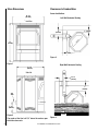
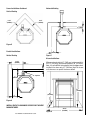
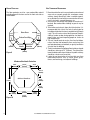
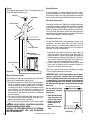
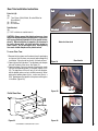
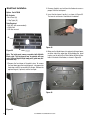
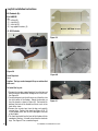
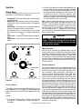
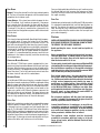
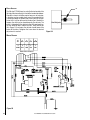
INSTALLATION AND OPERATION MANUAL
Free-Standing
Pellet Stove
Retain These Instructions
For Future Reference
P/N 775,228M, Rev. A, 05/2007
Pellet Stoves
Model Winslow™ (PS40)
A French manual is available upon request. Order P/N 775,228CF.
Ce manuel d’installation est disponible en francais, simplement en faire la demande. Numéro de la pièce
775,228CF.
These appliances must be properly installed and operated in order to prevent the possibility
of a house fire. Please read this entire installation and operation manual before installing and using your wood stove. Failure to follow these instructions could result in
property damage, bodily injury or even death. Contact your local building or fire
officials to obtain a permit and information on any installation requirements
and inspection requirements in your area.
Table of Contents
Features And Specifications ........................................................................................... 3
Listing Information .................................................................................................... 3
Appearance Choices .................................................................................................... 3
Stove Dimensions....................................................................................................... 4
Clearances To Combustibles .......................................................................................... 4
Hearth Protection .................................................................................................... 6
Vent Termination Requirements ....................................................................................... 6
Vent Termination Locations ......................................................................................... 7
Installation:
Venting ........................................................................................................... 8
Masonry Fireplace Installation .................................................................................. 9
Mobile Home Installation .......................................................................................10
Surge Protector ................................................................................................10
Outside Air ......................................................................................................10
Thermostat .......................................................................................................10
Door Trim Installation Instructions ............................................................................11
Door Grill Installation Instruction ............................................................................13
Brick Panel Installation Instructions ..........................................................................14
Log Set Installation Instructions . .............................................................................16
Operation:
Control Board ..................................................................................................17
Filling The Hopper ..............................................................................................17
Lighting Your Pellet Stove .....................................................................................17
Manual Operation ...............................................................................................17
Thermostat Operation ...........................................................................................17
Shut Down .......................................................................................................18
Paint Curing .....................................................................................................18
Convection Blower Operation ...................................................................................18
Operating Sounds . ..............................................................................................18
Pellet Fuel ......................................................................................................18
Corn Fuel ........................................................................................................18
Cautions .........................................................................................................18
Cleaning And Maintenance
Burn Pot Cleaning ..............................................................................................19
Cleaning Glass ..................................................................................................19
Ash Drawer Removal And Cleaning ............................................................................19
Cleaning The Heat Exchanger ..................................................................................20
Cleaning The Combustion Blower ...............................................................................20
Cleaning The Flue Gas Passageways ............................................................................20
Cleaning The Convection Blower ...............................................................................21
Cleaning The Vent Pipe ..........................................................................................21
Front Door Removal ...........................................................................................22
Side Door Removal .............................................................................................22
Back Removal And Lower Cover Plate .........................................................................23
Component Information
Igniter ..........................................................................................................23
Vacuum Switch .................................................................................................23
Auger And Auger Motor ......................................................................................23
Over Temperature Snap Switch (Manual Reset) ..............................................................23
Proof Of Fire Snap Switch .....................................................................................23
Convection Blower Snap Switch ..............................................................................23
Draft Adjuster .................................................................................................24
Wiring Diagram .................................................................................................24
Diagnostic Codes ....................................................................................................25
Troubleshooting .....................................................................................................25
Electrical Generator Operation .....................................................................................26
Replacement Parts List .............................................................................................26
Product Reference Information. .....................................................................................27
Features and Specifications
CAUTION: THE USE OF UNAPPROVED, DIRTY, WET
AND/OR HIGH SALT CONTENT FUEL WILL VOID THE
WARRANTY!
Installation Options
• Residential
• Vented vertical and horizontal (see venting instructions)
• Manufactured home and mobile home
• Thermostat or manual operation • Bedrooms
Heating
• Max. feed rate is 4.7 pounds/hour or 39,500 BTU/hour
• Min. feed rate is 1.8 pounds/hour or 15,120 BTU/hour
Venting
This stove is approved for venting with Type L and Type
PL pellet vent pipe. The flue collar on the stove accepts
3”diameter pipe.
The combustion air for this stove is drawn through a pipe
at the lower rear of the stove. For mobile home installations
a 3” ID flex line or pipe must be attached to the stove’s air
intake to draw air from outside the house. The vent pipe can
be installed vertically or horizontally (see Venting section
for recommended installations).
Electrical
•
•
•
•
The stove requires 120 volts AC for operation.
Maximum wattage is 700.
Igniter wattage is 400.
Normal operating wattage is 300.
Wood pellets manufactured to the pellet fuels institute (P.F.I.)
certification standard are available in two grades, Standard
and Premium. The primary difference between the two is
the ash content of the pellets.
The P.F.I. specification for standard grade & premium grade
residential pellet fuel is as follows:
• CHLORIDES (Salt): Less than 300 p.p.m. to avoid stove
and vent rusting.
• BULK DENSITY: 40 lb. / Cu. Ft. minimum
• MOISTURE CONTENT: 8% maximum
• ASH CONTENT: < 3% maximum (standard grade) < 1%
maximum (premium grade)
• FINES: 0.5% maximum through a 1/8” screen
• BTU CONTENT: There are a number of variations in pellet
fuels that are not included in PFI standards. For example,
BTU (heat value) content may range from just under 8,000
to almost 9,000 Btu, depending upon species and region
of the country and other variables.
Corn Specifications: Use only clean-shelled corn with a
moisture content less than 15% and approximate fuel value
of 7000 BTU/lb (16,200 kJ/kg). Do not attempt to burn corn
with higher moisture content or burn lesser grade fuels. Do
not burn other types of agricultural pellets or byproducts
(alfalfa, cherry pits, olive pits, nut shells, etc.) as they are
not permitted to be burned in these appliances.
Weight - 265 pounds
Hopper Capacity - 60 pounds
Thermostat
This stove can be operated manually or with a thermostat.
Lighting
This stove is equipped with an electric self igniter for ease
of ignition.
Fuel Specifications
This stove is designed to burn wood pellet fuel. In addition,
a corn/wood pellet mixture, with a maximum of 50 percent
corn can be burned. Burning any other fuel that is not approved for use with this appliance will void the appliance
warranty. IMPORTANT: The corn/wood mix needs to be
mixed evenly before being put in the Winslow™ pellet
stove hopper.
Wood Pellet Specifications: This appliance has been
designed to burn wood residue pellets with up to 3% ash
content. Dirty fuel will adversely affect the performance of the
stove. Any questions regarding pellet fuel can be answered
at the Pellet Fuels Institute (PFI), www.pelletheat.org.
Listing information
The Winslow™ PS40 stove is safety tested and listed with
the following agencies;
• OMNI-Test Laboratories, Inc., Beaverton, Oregon to ASTME
1509
• USEPA List of Exempt Wood Heating Appliances
• List of Colorado Approved Pellet Stoves
Appearance Choices
The Winslow PS40 stove can be ordered with the following
door trims and grills, log set, and brick panel options:
Door Trim Kits
Black
79038
Gold
79034
Nickel
79037
Brushed Nickel 79035
Black Nickel
79036
Grill Kits
Black
Gold
Nickel
Brushed Nickel
Black Nickel
Log Set - Required
H5142
Brick Panel Kit -Required
79030
NOTE: DIAGRAMS & ILLUSTRATIONS ARE NOT TO SCALE.
79000
79001
79002
79022
79039
Stove Dimensions
Clearances to Combustibles
Corner Installations
26-1/4”
(667mm)
Left Wall Horizontal Venting
FrontView
View
Front
Side View
3” (76mm)
8”
(203mm)
31”
(787mm)
8
3”
(76mm)
Figure 3
Figure 1
Right Wall Horizontal Venting
23-1/4”
(591mm)
Side View
Side
View
6-3/4”
(172mm)
7”
(178mm)
C/L
8
8-7/8”
(225mm)
7”
(178mm)
Figure 2
The center of the flue is 8-7/8” above the surface upon
which the stove rests.
Figure 4
NOTE: DIAGRAMS & ILLUSTRATIONS ARE NOT TO SCALE.
Corner Installations Continued
Horizontal Venting
Vertical Venting
5-7/8”
(149mm)
5-7/8”
(149mm)
3” (76mm)
Figure 5
Parallel Installations
8”
(203mm)
Figure 7
Vertical Venting
Alcove Installations
17-1/4”
(423mm)
3” (76mm)
9”
(229mm)
Minimum alcove height is 41” (1041mm), minimum width is
42-1/4” (1073mm), and maximum depth is 48” (1219mm).
Note, it is quite difficult to load pellets into the hopper when
installed in an alcove only 41” (1041mm) high. For alcove
wall clearances see parallel clearances below.
Top Vent
41”
(1041mm)
8”
(203mm)
48”
(1219mm)
Figure 6
INSTALL VENT AT CLEARANCES SPECIFIED BY THE VENT
MANUFACTURER.
Figure 8
NOTE: DIAGRAMS & ILLUSTRATIONS ARE NOT TO SCALE.
42-1/4”
(1073mm)
Vent Termination Requirements
Hearth Protection
The floor protector must be a non-combustible material
extending beneath the stove and to the front and sides as
shown below.
Stove Base
3-7/8”
(98mm)
3-7/8”
(98mm)
Firebox Front Edge
6”
(152mm)
Hearth
6”
(152mm)
Protection
6”
(152mm)
Figure 9
Minimum Size Hearth Protection
9-5/8”
(245mm)
14-1/4”
(362mm)
1. Do not terminate the vent in any enclosed or semi-enclosed
areas such as a carport, garage, attic, crawlspace, narrow
walkway, closely fenced area, under a sundeck or porch,
or any location that can build up a concentration of fumes
such as stairwells, covered breezeway, etc.
2. Vent surfaces can become hot enough to cause burns if
touched. Non-combustible shielding or guards may be
required.
3. Termination must exhaust above the inlet elevation. It is
recommended that at least five feet of vertical pipe be
installed outside when the stove is vented directly through
a wall. This will create a natural draft to prevent the possibility of smoke or odor during appliance shut down or
power failure and avoid exposing people or shrubs to
high temperatures.
4. The vent should terminate no less than four feet below,
no less than four feet horizontally from, and no less than
one foot above doors and windows, or gravity/ventilation
air inlets into the building.
5. The distance between the bottom of termination and grade
should be a minimum of 12” (305mm). The distance between the bottom of the termination and a public walkway
should be a minimum of seven feet.
6. Locate the vent termination at least two feet away from
combustible materials such as shrubs, plants, grass,
fences, roof overhangs, and adjacent buildings.
9-5/8”
(245mm)
10-3/4”
(273mm)
Outline of Stove Base
28”
8-7/8”
(225mm)
(711mm)
8-7/8”
(213mm)
7-9/16”
(192mm)
Figure 10
18-3/8”
(467mm)
7-9/16”
(192mm)
33-1/2”
(851mm)
NOTE: DIAGRAMS & ILLUSTRATIONS ARE NOT TO SCALE.
Vent Installation
Vent Termination Locations
Air Supply Inlet
Vent Terminal
Area Where Terminal Is Not Permitted
Vertical Terminal
24”
(610mm)
Vertical Terminal
G
(From Eave)
24”
(610mm)
A
D
E
Fixed Closed
B
B
M
H
N
C
B
B
L
K
J
F
A
B
A = Clearance above grade, veranda, porch, deck, or balcony (min. 12”/30cm)
B = Clearance to window or door that may be opened (min.
12”/30cm above - 48”/1.2m below and to the side)
C = Clearance to permanently closed window *(min.
12”/30cm)
D = Vertical clearance to ventilated soffit located above
the terminal within a horizontal distance of *(min.
24”/60cm) from the centerline of the terminal (min.
22”/55cm) check with local code.
E = Clearance to unventilated soffit *(min. 12”/30cm)
F = Clearance to outside corner *(min. 12”/30cm)
G = Clearance to inside corner *(min. 12”/30cm)
H = Not to be installed above a meter/regulator assembly
within *(min. 36”/90cm) horizontally from the centerline of the regulator.
J = Clearance to service regulator vent outlet *(min.
72”/1.8m)
K = Clearance to non-mechanical air supply inlet to building or the combustion air inlet to any other appliance
*(min. 48”/1.2m)
Able To Open
L = Clearance to a mechanical air supply inlet *(min.
120”/3.1m)
M = **Clearance above paved sidewalk or a paved driveway
located on public property *(min. 84”/2.1m)
N = ***Clearance under veranda, porch, deck, or balcony
(min. 12”/30cm)
Note:
*
Local codes or regulations may require different clearances.
**
A vent shall not terminate directly above a sidewalk or
paved driveway which is located between two single
family dwellings and serves both dwellings.
*** Only permitted if veranda, porch, deck, or balcony is
fully open on a minimum of two sides beneath the
floor.
Figure 11
NOTE: DIAGRAMS & ILLUSTRATIONS ARE NOT TO SCALE.
Venting
Pellet pipe type PL or L must be used to vent the Winslow™
PS40 stove. Single wall pipe cannot be used with this pellet
stove. The stove’s flue collar is 3” in diameter. An approved
wall thimble or approved ceiling firestop must be used when
the pellet pipe passes through a combustible wall or ceiling.
The stove’s combustion blower pressurizes and pushes flue
gases out the pellet pipe. As a result, all pipe joints should
be locked together or screwed with three screws if the pipe
does not have a locking system and sealed with high temperature silicone. The pipe should be siliconed and fastened
with three screws to the stove’s flue collar.
The longer the run of pipe and the more elbows used, the
greater the resistance to the flow of flue gases. Four inch
diameter pellet pipe is recommended for pipe runs greater
than 15 feet or when a number of elbows are used.
To aid in cleaning, whenever possible, the venting system
should include a tee with clean out attached to the flue collar on the stove.
DO NOT INSTALL A FLUE DAMPER IN THE EXHAUST VENTING SYSTEM OF THIS UNIT. DO NOT CONNECT THIS UNIT
TO A CHIMNEY FLUE SERVING ANOTHER APPLIANCE.
Horizontal &
Up Through
the Eave
Horizontal installations that terminate without any vertical
sections of pipe are approved; however, wind may direct
flue gases toward the house causing discoloring problems.
For this reason, horizontal and up 5 feet or horizontal and
through the eave installations are recommended.
Horizontal & UP 5’
45°
90°
Wood
Stove Pipe
Retrofit
The Winslow
PS40 stove stove
can be vented
into existing 6”
or 8” diameter
wood stove pipe.
NOTE: DIAGRAMS & ILLUSTRATIONS ARE NOT TO SCALE.
Masonry Chimney
Fireplace
When venting into a masonry chimney, the pellet pipe can
terminate just inside the chimney. However, it is recommended to run the pellet pipe to the top of the chimney.
When venting into a fireplace chimney, the pellet pipe can
terminate just above the damper. However, it is recommended
to run the pellet pipe to the top of the chimney.
Figure 16
Figure 18
Figure 17
Figure 19
NOTE: DIAGRAMS & ILLUSTRATIONS ARE NOT TO SCALE.
Vertical
If the length of pipe exceeds 15 feet, 4 inch pipe rather than
3 inch vent pipe should be used.
Rain Cap
Storm Collar
Surge Protectors
A surge protector is recommended to ensure the stove’s
electrical components are not damaged due to a surge in
the electrical supply. Only high quality protectors should be
used - cheap ones do not provide the protection needed.
Outside Air Installations
Roof Flashing
Connecting the Winslow PS40 stove to outside combustion
air is optional, except in mobile home installations and when
required by local building codes. The stove’s air intake will
accept 3” ID pipe to accommodate outside air installations.
The air intake on the exterior of the home should always be
located substantially below the flue termination and terminate
with a cover to keep out weather and pests.
Thermostat installation
Ceiling Firestop
Listed Pellet Pipe
Outside Air Pipe
1) Unplug the stove from the electrical outlet. Open the
right side door and lift out the control board from its
retaining brackets. Locate the light green wiring block at
the bottom back of the board (see Figure 21), loosen the
two screws B at the back of the block, and remove the U
shaped jumper wire A protruding from the block.
2) Insert a wire from the thermostat into one of the slots
from which the jumper wire was removed. Repeat this
process for the other thermostat wire.
Retain the jumper wire for future reinstallation. See page
17 for thermostat operation instructions.
Figure 20
Mobile Home Installations
10
The Winslow PS40 stove can be operated manually or by
thermostat. The stove comes from the factory wired to
operate manually - see control board operation on the following page. A low voltage thermostat can be installed on
the stove. To install the thermostat:
The following are required for installation of the Winslow™
PS40 stove in mobile homes. See Figure 20.
1. Connecting the Winslow PS40 stove to outside combustion air is optional, except in mobile home installations
and when required by local building codes. The stove’s
air intake will accept 3” ID pipe to accommodate outside
air installations. The air intake on the exterior of the
home should always be located substantially below the
flue termination and terminate with a cover to keep out
weather and pests.
2. The stove must be fastened to the floor using lag screws.
The screws can be inserted through the holes in the
pedestal located behind the side doors.
3. The stove must be grounded with a #8 or larger copper
wire.
WARNING: DO NOT INSTALL THIS STOVE IN A SLEEPING
ROOM IN A MANUFACTURED HOME.
CAUTION: THE STRUCTURAL INTEGRITY OF THE MANUFACTURED HOME FLOOR, WALL, AND CEILING/ROOF
MUST BE MAINTAINED.
IMPORTANT NOTE: Install the thermostat per the manufacturers instructions, provided with the thermostat.
Failure to follow manufacturers instructions could result
in a malfunction. Pay special attention to the thermostat
location requirements. If the location requirements are
not adhered to the appliance, erratic operation or failure
may occur.
Rear View of Control Board
Do not mount the thermostat where it may be
affected by:
• Radiant heat from the
stove, fireplaces, sun
or other heat sources.
• Drafts or dead spots
behind doors or in
corners.
• Hot or cold air from
ducts.
NOTE: DIAGRAMS & ILLUSTRATIONS ARE NOT TO SCALE.
Wiring Block
Figure 21 A
B
Door Trim Installation Instructions
(A)
Parts List (A):
Qty
(2) Trim Pieces (Gold, Nickel, Brushed Nickel or
Black Nickel )
(6) #10 nuts
(6) #10 washers
Tools Needed:
Qty
(1) 3/8” nut driver or socket wrench
Trim Pieces
Trim Screws
Figure 23
CAUTION: Always ensure that plated surfaces are clean
and free of fingerprints before lighting stove. Fingerprints
will leave permanent blemishes if left on plated surface
when lit. When installation is complete, the trim should
be gently cleaned with soft cloth and either alcohol or
glass cleaner. Do not overtighten nuts, overtightening
can create visible dimples on the plated surface.
#10 washers
Holes for trim studs
To install Door Trim:
1. Remove the trim pieces and hardware from its packaging
and ensure that all pieces are present before beginning
installation. Take care not to scratch finished surfaces.
2. Open right and left side door. The side doors swivel open
towards the back of the stove. See Figure 24.
3. Open front door. Put trim in place by inserting trim studs
into the corresponding holes in the door (Figures 22 &
25). The top piece of trim will only fit in one direction,
but the bottom piece can be installed incorrectly. When
placing the bottom piece of trim, make sure there is a
9/16” gap between the top of the trim piece and the glass
in the door. (Figure 26)
Figure 24
Figure 25
Door Handle
Trim stud
Pellet Stove Door
Top of Trim
Trim Pieces
Figure 22
Figure 26
NOTE: DIAGRAMS & ILLUSTRATIONS ARE NOT TO SCALE.
11
4. Place one washer on each stud. Using a 3/8” nut driver,
snug up the nuts on each piece of trim. Do not finish
tightening the nuts yet. See Figure 27.
5. There should be approximately a 7/8” (22mm) gap between
the top edge of the upper trim and the top edge of the
door and a 1-1/2” (38mm) gap between the bottom trim
to the bottom of the door. Visually inspect the alignment
of the trim and adjust if necessary. See Figure 28.
6. Finish tightening nuts. CAUTION - DO NOT OVER-TIGHTEN
NUTS, DIMPLING OF THE TRIM WILL OCCUR!!!
Figure 28
Figure 27
12
NOTE: DIAGRAMS & ILLUSTRATIONS ARE NOT TO SCALE.
Door Grill Installation Instructions
Parts Needed:
Qty
(4) Button Head Screws (already in place in stove)
Tools Required:
Qty
(1) 1/8” allen wrench
3. Rotate the grill back to the horizontal position and re-install
the four button head screws through the two holes at each
end of the grill and into the stove body. See Figure 31.
Rotate Grill Back To Horizontal Position
To install the Grill:
1. Remove the four button head screws from body of the
stove with a 1/8” allen wrench. See Figure 29.
Button Head Screw
Figure 31
Re-install Button Head Screws
Figure 29
2. Pull the scraper rod out, rotate the grill vertically, (with
the notch to the left) and slide the grill over the scraper
rod (slide the rod between the third and fourth bar). See
Figure 30.
Notch
Slider Rod
Figure 32
Between 3rd & 4th Bar
Figure 30
NOTE: DIAGRAMS & ILLUSTRATIONS ARE NOT TO SCALE.
13
Brick Panel Installation
2. Remove all pellets and ash from the firebox to ensure a
proper fit for the brick panel.
Option: Part #79030
3. Insert the brick panel, top first, as shown in Figure 35.
The two cut out corners should be at the bottom.
Kit Contents:
- Brick Panel (A)
- 4 Tap Tights (B)
Tools Required:
- Drill (90° drill recommended)
- #18 drill bit
- 5/32 allen wrench
A
Figure 35
Figure 33
B
Note: The brick panel comes pre-painted with Metallic
Black paint. The brick panel may be painted with any
color of Stove Bright® high-temp paint (paint may discolor with use).
4. Make sure that the brick panel is centered, with equal space
on either side of the auger tube. While holding the panel
in place, use the drill with a #18 drill bit to drill out the four
holes in the back of the firebox, as shown in Figure 36.
1. Remove the front door of the pellet stove. To remove
the front door, open the two side panels, swing open the
front door, and lift it up and off of its hinges. Remove the
optional log set, if present, and the burn pot.
Figure 36
Figure 34
14
NOTE: DIAGRAMS & ILLUSTRATIONS ARE NOT TO SCALE.
Log Set installation Instructions
Kit Contents (A):
Part #H5142
Qty
(1) left log (B)
(1) right log (C)
(1) front log (D)
(2) log support brackets (E)
cut lines
A - Kit Contents
C
B
Figure 39
bracket in place correctly
D
E
E
Figure 38
Figure 40
Tools Required:
None
C
B
Caution: The logs can be damaged if they are not handled
with care!
To Install the log set:
1. Remove the two log support brackets from the box and
bend the ends of the brackets 90 degrees at the cut lines.
See Figure 39.
2. One bracket goes into the left corner and the other into
the right corner of the firebox. Rotate the brackets so
they are placed as shown in Figure 40. The bracket fits
between the back of the firebox and the air wash at the
front of the stove.
3. Remove the ceramic logs from the box and carefully
unwrap them. Position each back log (Figure 41, B, C)
in their proper place, one on each side against the back
of the firebox.
4. The front log should face the front of the firebox with the
woodgrain showing. It should rest on the other two back
logs. See Figure 41 for assembled log set.
16
D
Figure 41
NOTE: DIAGRAMS & ILLUSTRATIONS ARE NOT TO SCALE.
Operation
Control Board
The control board regulates all functions of the stove. The
following is a list of the board’s components:
• Feeding light - lights up when the auger is feeding pellets
into the burn pot.
• Ready Light - lights up when stove is ready to operate.
Igniting Light - lights up when the stove is in the ignition
sequence.
• Start Button - is pushed to start the ignition sequence
after the heat selector knob is turned from off.
Heat Selector Knob - is turned to off to shut the stove
off or turned to a setting from 1 to high to regulate the
burn rate.
• Igniter Fuse - six amp fuse to protect igniter heating element.
• Control Fuse - three amp fuse to protect the control
board.
2. Push the start button and the ignite and feeding lights will
come on and the lighting sequence will begin. For about
the next 15 minutes the stove will feed pellets cyclically
into the burn pot, the combustion fan will come on, and
the igniter will heat up. During this sequence, some
smoke in the firebox is to be expected. After the igniting
sequence is complete, the stove will begin burning at the
level indicated by the heat selector knob.
Note: Upon the stove’s initial light up, or if the stove has
previously run out of pellets, the auger feed tube may not
contain a sufficient number of pellets to allow the stove
to continue burning after the ignition sequence. It may be
necessary to push the start button a second time to run
the start sequence again. It is important to always empty
(when cool) the burn pot of pellets before pushing the start
button a second time.
WARNING
Never empty pellets from the burn pot into the
hopper. Pellets that may appear to be cool may
retain enough heat to ignite other pellets resulting
in smoke or fire damage.
Manual Operation
After the stove is burning (see lighting above), the heat
selector knob controls the pellet burn rate and the stove’s
heat output. Turning the knob to setting 1 allows the stove
to burn about 1.8 pounds of pellets per hour - about 8,500
BTUs per hour. Turning the knob to high allows the stove
to burn 4.7 pounds of pellets per hour - about 39,000 BTUs
per hour. Once set, the stove will continue to burn at this
rate until shut off.
Thermostat Operation
Heat Selector
Knob
Figure 42
Filling the Hopper
The hopper can be accessed by lifting the lid at the rear
of the top of the stove. The hopper will hold 60 pounds of
pellets. Remove any contents from the hopper and fill with
pellets.
Lighting
This stove will operate with a low voltage thermostat. See
page 10 for instructions on installing the thermostat. Once
installed, the thermostat will control the operation of the
stove. Important: When connected to a thermostat, it is
necessary to push the ignite button for the initial burn,
when the electrical flow to the stove is interrupted, if the
selector knob is turned to off (and then back on), or if the
stove runs out of pellets and therefore shuts off. After the
initial ignition sequence, when the thermostat calls for heat
(the room temperature is less than the temperature set on
the thermostat) and the heat selector knob is not in the off
position, the stove will burn at the heat selector knob setting. The higher the setting, the quicker the room will heat
up. Once the thermostat no longer calls for heat (the room
is up to the desired temperature), the stove will continue
to burn for one additional hour at the lowest setting. If the
thermostat does not call for heat again during that hour, the
stove will shut off. During that hour, if the thermostat calls
for heat again, the stove will again burn at the heat selector
knob setting until the thermostat no longer calls for heat.
If the stove shuts off after that hour it will relight when the
thermostat calls for heat.
1. Turn the heat selector knob (see Figure 42) to the heat
level desired - 1 through high - and the ready light will
turn green.
NOTE: DIAGRAMS & ILLUSTRATIONS ARE NOT TO SCALE.
17
Shut Down
Normal - To turn the stove off, turn the heat selector knob to
off. The fans will continue to operate until the control board
completes the shut down cycle.
Power Outage - If the stove loses electrical power for less
than 10 seconds it will continue to operate. If the power
loss is greater than 10 seconds, the stove will go into the
ignition sequence and normal operation when the power
is restored. If the stove is connected to a thermostat, the
stove will not start the ignition sequence until the thermostat
calls for heat.
Paint Curing
This stove has been painted with StoveBright high temperature metallic paint. It leaves the factory dry to the touch,
but completes the curing process as the stove is used. The
paint will cure during the first few times the stove is burned.
Also some parts of the appliance may be lightly coated with
machining oil. Ventilate the house during these first firings
as the paint and oil give off carbon dioxide and unpleasant odors. It is recommended that persons sensitive to an
imbalance in the indoor air quality avoid the stove during
the curing process.
Convection Blower Operation
Your Winslow™ PS40 stove comes equipped with a temperature activated convection blower that extracts heat from
the stove. After the stove warms up, a heat activated switch
will turn the fan on. The speed of the fan varies with the burn
rate of the stove. The fan will continue to extract heat after
the stove shuts off and until it is cooled down.
Operating Sounds
As the Winslow PS40 stove is burning, a number of normal
operational sounds may be heard. Pellets can be heard sliding
down the auger tube and into the burn pot. Also, the motor
powering the auger can be heard as the control board calls
for pellets. Occasionally a loud noise can be heard as the
auger cuts a pellet in half. When the blowers come on, the
sound of rushing air may be heard. The lower the burn rate
the slower the fan operates. Hourly, the combustion fan will
blow at a high speed to clean ash from the burn pot.
Pellet Fuel
Pellet fuel is made from sawdust and scrap wood from many
different species of wood. Pellets are either 1/4” or 5/16”
in diameter and vary in length (see Fuel Specifications on
page 3). The Winslow PS40 stove will burn either diameter
pellets. Pellets made from hardwoods contain more ash than
those made from softwoods. Minerals from ash and sand in
the pellets form clinkers under the extreme temperatures in
the burn pot. Try burning various brands of pellets until you
find one that burns with minimum ash and clinkers.
18
Once you find a pellet brand that burns well, continue using
this brand. High ash fuel increases the frequency of stove
cleaning. Fuel with an excessive moisture content may jam
the auger assembly.
Corn Fuel
Shelled corn can be burned in the Winslow PS40 stove when
it is mixed with wood pellet fuel (see Fuel Specifications on
page 3). The mixture can contain a maximum of 50 percent
corn. Burning corn may create more ash than wood pellets
and may necessitate the need to clean the burn pot and
glass more frequently.
Cautions
INSTALLATION AND REPAIR SHOULD ONLY BE PERFORMED
BY A QUALIFIED SERVICE TECHNICIAN. DO NOT ATTEMPT
TO SERVICE THE APPLIANCE YOURSELF.
Avoid overfiring the stove - do not hand feed pellets to
the appliance.
Never use gasoline, gasoline-type lantern fuel, kerosene,
charcoal lighter fluid, or similar liquids to start or fresh
up a fire in this heater. Keep all such liquids well away
from the heater while it is in use.
For your safety, do not install or operate your Winslow PS40
stove without first reading and understanding this manual.
Any installation or operation of the appliance deviating
from that which is stated in this instruction manual WILL
void the warranty and may be hazardous.
Due to high temperatures, the stove should be located
out of traffic areas and away from furniture and draperies. Children and adults should be alerted to the hazards
of high surface temperature and should stay away to
avoid burns or clothing ignition. Young children should
be carefully supervised when they are in the same room
as the Winslow PS40 stove. Clothing or any other flammable material should not be placed on or near the stove.
Any grill, panel, or glass removed for service MUST be
replaced prior to operating the stove.
Do not operate appliance with the glass front removed,
cracked, or broken. Replacement of the glass should be
done by a qualified service technician.
Lennox Hearth Products, its employees, or any of its representatives assume no responsibility for any damages
caused by an inoperable, inadequate, or unsafe condition
as a result of any improper operation, service, or installation procedures, whether direct or indirect.
The appliance, when installed, must be electrically
grounded in accordance with local codes or, in the absence of local codes, with the National Electrical Code,
ANSI/NFPA 70.
NOTE: DIAGRAMS & ILLUSTRATIONS ARE NOT TO SCALE.
Cleaning and Maintenance
Unplug and let the Winslow™ PS40 stove cool before performing any maintenance or cleaning. Some brands of pellets
produce more ash and clinkers than others. Therefore the
frequency of performing the following cleaning procedures
depends to a great degree on the quality of the pellets burned.
Not cleaning this unit will cause it to burn poorly and will
void your stove’s warranty.
Reinstall the ash drawer by inserting the drawer in the stove
and refastening the left and right latches securely. Note that
if the ash drawer does not seal tightly to the stove, the control
board may detect a leak and shut the stove down.
High Side Of Burn Pot Goes
Toward Front Of Stove
Burn Pot Cleaning
The combustion fan comes on at high speed once an hour
to blow the byproducts of combustion out of the burn pot.
However, the burn pot should be cleaned more throughly
after burning about 10 bags of pellets. The burn pot has
a number of holes in the bottom and sides that provide
combustion air to the pellets. The extreme temperatures in
the burn pot can cause the impurities in the pellets to form
ash and clinkers. When the stove is cool, open the front
door and lift out the cast iron burn pot. Scrape the inner
bottom and sides of the pot with a screwdriver to remove
all ash and clinkers from these surfaces. Make sure all the
holes in the pot are open. Place the burn pot in the hole
from which it was removed. Make sure the high side of the
pot is rotated toward the front of the stove (see Figure 43).
Push the burn pot down so surface A is tight against the
steel supporting the pot. Do not substitute any other grate
or pot for use in this stove.
A
Figure 43
Cleaning Glass
Caution: Do not open the front door when the stove is hot.
To open the door, follow the first two steps listed in Front
Door Removal (see page 22). Clean the glass using a soft
cloth or paper towel and Windex or wood stove window
cleaner. A damp cloth with a small amount of ash from
the firebox can also be used to clean the glass.
Ash Drawer Removal and Cleaning
Caution: Do not remove the ash drawer when the stove
is hot. To remove the ash drawer, swing open the left and
right side doors. Rotate the lever on latch B (see Figure
44) out from the stove to release the ash drawer. Do the
same with the latch on the right side of the stove. Pull the
ash drawer forward and away from the stove.
Caution: Disposal of Ashes - Ashes should be placed
in a metal container with a tight fitting lid. The closed
container should be placed on a non-combustible floor or
the ground - well away from all combustible materials,
pending final disposal. If the ashes are disposed of by
burial in soil or otherwise locally dispersed, they should
be retained in the closed container until all cinders have
been thoroughly cooled.
Latch
Latch
B
Figure 44
NOTE: DIAGRAMS & ILLUSTRATIONS ARE NOT TO SCALE.
B
19
Cleaning the Heat Exchanger
Caution: Do not operate the heat exchange scraper when
the stove is hot. Located at the center of the grill on the top
front of the stove is a bent rod that is attached to a scraper
on the heat exchange tubes. To remove ash build-up and
maintain efficient heat extraction from the stove, this rod
should be pulled in and out at least once a week.
A
A
Cleaning the Combustion Blower
To clean the combustion blower, remove the six nuts labeled
A in Figure 46 with an 11/32” wrench. After removing these
nuts, the motor with fan attached can be pulled from the
fan housing. The fan blades and the fan housing can be
vacuumed once the motor is removed. When reinstalling
the motor, a new gasket may need to be installed between
the motor and the fan housing. To complete the reinstallation, place the motor back on the fan housing and reinstall
the six nuts. Make sure the motor’s green ground wire is
secured under one of the nuts.
Cleaning the Flue Gas Passageways
Figure 46
Cleaning the flue gas passageways should be done at least
once a year. Burning high ash pellets may require this
cleaning to be done more often. Clean these passageways
only when the stove and ash are cold - do not start a fire
in the vacuum cleaner by vacuuming up hot ash. On each
side of the stove there are two access covers (see B and C
in Figure 47) that can be removed by unscrewing the two
5/32” allen head screws. Insert a cleaning brush in the
openings to loosen any ash build-up and use a vacuum
cleaner to remove the loosened ash. Reinstall the covers
when cleaning is complete.
BB
There are also two more access holes located behind the
ash drawer. Remove the ash drawer (see previous page) and
loosen the two 5/16” screws with a 1/2” socket or wrench,
the screws are shown as D in Figure 45. Rotate the covers
over the access holes and use a brush and vacuum to clean
the ash. Rotate the covers back over the holes and tighten
the screws.
CC
DD
Figure 47
Front View Looking into the Ash Drawer
Cavity with the Ash Drawer Removed
Figure 45
20
NOTE: DIAGRAMS & ILLUSTRATIONS ARE NOT TO SCALE.
Front Door Removal
Caution: Do not open the front door when the stove is hot.
To remove the door, swing the left and right side doors A
open. Pull the front door handle B to the front and swing
the front door open. Lift the front door up and off the hinges
as shown in C in Figure 49. To reinstall the door repeat the
steps in reverse order.
C
Side Door Removal
A
To remove the door,
1 Swing the door open,
2 Lift the door up, and
3. Pull the bottom of the door out and down - pulling the
top hinge pin out of the retaining hole in the top hinge
bracket.
To reinstall the door, slide the pin on the top of the door up
and into the hole in the upper hinge bracket. Slide the pin
on the bottom of the door into the hole in the pedestal base
and rotate the door closed.
22
NOTE: DIAGRAMS & ILLUSTRATIONS ARE NOT TO SCALE.
B
Back Removal and Lower Cover Plate
To remove the back:
1. Remove the left and right side panels (see the previous
page).
2. If the stove is connected to the vent pipe, loosen the four
5/32” allen head screws (see A in Figure 51) securing the
lower cover plate beneath the flue outlet, lift the plate
slightly, and pull the plate off.
3. Loosen the two screws B and C shown in Figure 52 and
the corresponding two screws on the other side of the
stove. The back can now be pulled to the rear and off of
the stove.
Flue Outlet
Air Intake
A
To reinstall the back, follow the steps just listed - but in the
reverse order.
Component Information
The following is a list of components and their functions.
Igniter
The Winslow™ PS40 stove comes equipped with an automatic
igniter for lighting the fuel when the stove is in the lighting
mode. The igniter superheats air that is pulled through the
burn pot by the combustion blower to light the fuel. The
igniter remains energized for the first seven minutes of the
lighting sequence.
Vacuum Switch
The Winslow PS40 stove has a vacuum switch located
behind the left door, fastened to the pedestal base (see D
in Figure 52). If a low pressure is created in the firebox by
a leak, opening the front door, a blocked flue, or unsealed
ash drawer, the vacuum switch will sense it and cause the
stove to go into a shutdown mode.
Auger and Auger Motor
The 1.25 RPM auger motor turns the auger, lifting pellets
up the auger tube. The pellets are then dropped down a
tube and into the firepot. The auger is controlled by the
control board.
Over Temperature Snap Switch (Manual Reset)
(Opens at 225F) This switch is installed on the convection
blower (see F in Figure 53) and shuts the stove down if it
senses excessive temperatures. This snap switch has a reset
button on it and will not allow the stove to start up until the
reset button has been pushed.
Proof of Fire Snap Switch
(Closes at 140F) This switch is installed on the combustion
blower (see E in Figure 52) and shuts the stove down if it
senses no fire in the burn pot.
Convection Blower Snap Switch
(Closes at 120F) This switch is installed on the right rear
of the firebox and turns the convection blower on when the
stove gets up to temperature.
NOTE: DIAGRAMS & ILLUSTRATIONS ARE NOT TO SCALE.
23
Draft Adjuster
A
The Winslow™ PS40 stove has a draft adjuster located at the
left side of the stove directly in front of the combustion blower.
Should the stove installation require long runs of vent pipe,
a situation may be created where excessive combustion air
is flowing through the firebox and causing the fuel to burn
faster than it can be delivered to the burn pot. Should this
happen, the draft can be slowed down by the adjuster. The
stove is shipped with the adjuster in the fully open position.
To slow the draft down, loosen the 5/32” allen head screw
(A in Figure 54) and move the adjuster handle toward the
center of the stove. Retighten the screw when the desired
adjustment is reached.
Draft Adjuster
Figure 54
Wiring Diagram
10
YEL
9
RED
8
WHT
7
GRY
6
BRWN
5
ORNG
4
BLK
3
GRN
2
BLU
1
VIOL
Molex 10 Pin Connector
Figure 55
24
NOTE: DIAGRAMS & ILLUSTRATIONS ARE NOT TO SCALE.
Diagnostic Codes
If the stove operates abnormally, the ready light on the control board will signal the nature of the abnormal operation. The
following is a list of possible signals or codes:
Ready light is constant red Ignition Failure
Ready light flashes red 1 short and 1 long blink
Vacuum Switch Open
Ready light flashes red 2 short blinks
Proof of Fire Snap Switch Open
Ready light flashes red 2 long blinksOver Temperature Snap Switch Open
Troubleshooting
Ignition Failure - Code - Ready light is constant red and ignite light flashes two short blinks
Possible Problem
Hopper is out of pellets
Solution
Fill the hopper with pellets
Auger tube was not full of pellets when start button was pushed When cool, empty pellets in burn pot and push start button again
Burn pot dirty - holes plugged
Clean the burn pot
Igniter not functioning
Replace the igniter
Igniter fuse blown
Replace 6 amp fuse located on front of the control board
Control Board has no Power - When selector knob is turned no lights light up
Possible Problem
Solution
Power cord is not plugged in
Plug in power cord
Board fuse blown
Replace 3 amp fuse located on front of control board
Wall outlet not energized
Check circuit breaker panel
Board broken, damaged, or defective
Replace the control board
Vacuum Switch Shuts Stove Down - Code - Ready light flashes red 1 short and 1 long blink
Possible Problem
Solution
Front door is not sealing
Latch or adjust the front door or replace door gasket
Ash drawer is not sealing
Close latches, adjust latches, or replace drawer gaskets
Flue gas passageways restricted
Clean the passageways (see page 20)
Vent pipe restricted
Clean the vent pipe (see page 21)
Vacuum hose plugged
Clean or replace the vacuum hose
Vacuum switch defective
Replace the vacuum switch
Proof of Fire Snap Switch Shuts Stove Down - Code - Ready light flashes red 2 short blinks
Possible Problem
Hopper is out of pellets
Solution
Fill the hopper with pellets
Auger tube was not full of pellets when start button was pushed When cool, empty pellets in burn pot and push start button again
Snap switch* defective
Replace the snap switch
Over Temperature Snap Switch Shuts Stove Down - Code - Ready light flashes red 2 long blinks
Possible Problem
Solution
Convection blower not running
Blower dirty, blower snap switch bad, or blower broken
Flue passageways or vent restricted
Clean passageways or vent pipe (see pages 20 & 21)
Snap switch* defective
Replace the snap switch*
* Note: The snap switch has a reset button that must be pushed before stove will function (see page 23).
25
Orange Sooty Flames - Glass turns Black
Possible Problem
Solution
Burn pot is dirty
Clean the burn pot
Vent pipe restricted
Clean the vent pipe
Flue gas passageways restricted
Clean the passageways
Combustion blower dirty
Clean the combustion blower
Pellets not Feeding
Possible Problem
26
Solution
Hopper empty
Fill the hopper
Auger jammed
Call service technician
Flue gas passageways restricted
Call service technician
Auger motor not operating
Call service technician
Electrical Generator Operation
Replacement Parts
Your Winslow™ PS40 stove can be powered with a gas
driven electrical gererator. However, the generator’s electrical
regulator may not be compatible with the stove’s electronics. The higher the quality of the gererator, the greater the
chance that it is compatible with the stove.
Winslow PS40 stove
Cat. No.
H6006
H3111
H3113
H5912
H5886
H5921
H5875
H5856
H5899
H6018
H5900
H5903
H5917
H5978
79020
H5884
H5902
H5904
H3112
79040
H6037
H5911
79021
H6005
H5891
H6004
H5887
H3114
H6174
H5916
H5833
H5832
H6035
H6036
H6175
H5898
H5889
H5892
Description
Adjustable Latch Pin
Ash Clean Out Cover, 2 Per Stove
Ash Drawer
Ash Drawer Latch W/hardware 2 Per Stove
Auger Motor
Auger W/lower Bearing
Blower Snap Switch
Cast Burn Pot
Cleanout Cover Gasket
Combustion Blower
Combustion Gasket Housing To Stove
Combustion Gasket Motor To Housing
Conrol Board Access Latch
Control Board
Control Board Fuse 3amp, 5pk
Convection Blower
Convection Blower Gasket
Door Gasket 1 Ft (7ft Per Door)
Door Handle Assembly
Door W/glass (No Trim)
Flue Restrictor W/hardware
Hopper Door Wire
Igniter Fuse 6amp, 5pk
Igniter W/hose Clamp
Overtemp Switch
Power Cord
Proof Of Fire Switch
Side Ash Cover Clean Out
Side Door, Left
Side Door Magnet
Side Door W/control Access, Right
Stove Back
Stove Back Cover Plate
Top Side Door Bracket, Right
Top Side Door Bracket, Left
Vacuum Line 12” Piece
Vacuum Switch
Wiring Harness
Warranty
Your pellet stove is covered by a limited warranty (provided with appliance). Please read the warranty to be familiar with its coverage.
Retain this manual. File it with your other documents for future reference.
Product reference information
We recommend that you record the following important information
about your fireplace. Please contact your Lennox Hearth Products dealer
for any questions or concerns. For the number of your nearest Lennox
Hearth Products dealer, please call 1-800-9-LENNOX.
Replacement parts
See Page 26 for a complete replacement parts list. Use only parts supplied from the manufacturer.
Normally, all parts should be ordered through your Lennox Hearth
Products distributor or dealer. Parts will be shipped at prevailing prices
at time of order.
When ordering repair parts, always give the following information:
1. The model number of the appliance.
2. The serial number of the appliance.
3. The part number.
4. The description of the part.
5. The quantity required.
6. The installation date of the appliance.
If you encounter any problems or have any questions concerning the
installation or application of this system, please contact your dealer.
LENNOX HEARTH PRODUCTS
PO Box 987
Auburn, WA 98071
Visit us at www.Lennox.com
Your Stove’s Model Number_ __________________________________________
Your Stove’s Serial Number____________________________________________
The Date On Which Your Stove Was Installed______________________________
Your Dealer's Name__________________________________________________
Your Dealer's Phone Number___________________________________________
27
Lennox™ reserves the right to make changes at any time, without notice, in design,
materials, specifications, prices and also to discontinue colors, styles and products.
Consult your local distributor for fireplace code information.
Printed in U.S.A. © Lennox Hearth Products 2007
P/N 775,228M REV. A 05/2007
1110 West Taft Avenue • Orange, CA 92865