1
E
1
Parameters in the LCD display screen “ ”
Parameters displayed in the LCD screen are enclosed in
double quotation marks “ ”.
About this manual
This “Parameter Guide” contains explanations and other
information regarding the operations of the parameters and
settings on the TRITON STUDIO. The explanations are organized by mode, and page. Explanations and other information on the effects and their parameters are also provided for
each effect.
Refer to this guide when an unfamiliar parameter appears in
the display, or when you need to know more about a particular function.
Conventions in this manual
References to the TRITON STUDIO
The TRITON STUDIO is available in 88-key, 76-key and 61key models, but both models are referred to without distinction in this manual as “the TRITON STUDIO.” Illustrations
of the front and rear panels in this manual show the 61-key
model, but the illustrations apply equally to the 88-key and
76-key models.
Abbreviations for the manuals BG, PG, VNL
References to the manuals included with the TRITON STUDIO are abbreviated as follows in this document.
BG: Basic Guide
PG: Parameter Guide
VNL: Voice Name List
Boldface type
Parameter values are printed in boldface type.
Content that is of particular importance is also printed in
boldface type.
Procedure steps 1 2 3 ...
Steps in a procedure are listed as 1 2 3 ...
☞p.■, ☞■ – ■
These indicate pages or parameter numbers to which you
can refer.
Symbols
,
,
,
,
,
These symbols respectively indicate cautions, advice, MIDIrelated explanations, a parameter that can be selected as an
alternate modulation source, a parameter that can be
selected as a dynamic modulation source, and a parameter
that can use the BPM/MIDI Sync function.
Example screen displays
The values of the parameters shown in the example screens
of this manual are only for explanatory purposes, and may
not necessary match the values that appear in the LCD
screen of your instrument.
MIDI-related explanations
CC# is an abbreviation for Control Change Number.
In explanations of MIDI messages, numbers in square
brackets [ ] always indicate hexadecimal numbers.
Keys and knobs [ ]
References to the switches, dials, and knobs on the TRITON
STUDIO’s panel are enclosed in square brackets [ ]. References to buttons or tabs indicate objects in the LCD display
screen.
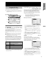
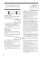
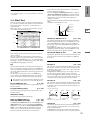
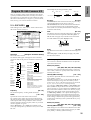
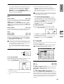
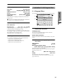
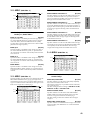
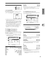
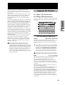
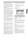
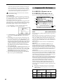
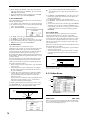
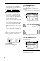
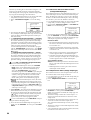
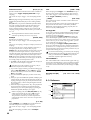
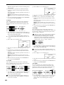
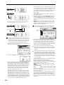
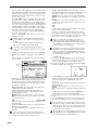
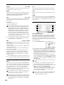
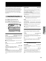
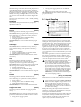
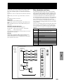
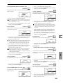
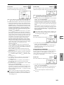
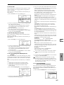
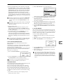
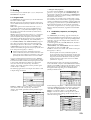
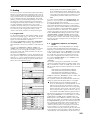
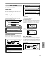
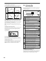
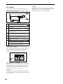
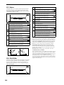
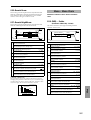
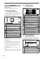
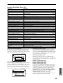
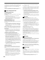
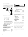
How to read the “Parameter Guide”
(example)
Page menu command No.
Mode name
Page No.
Program P5: Edit-Common LFO
Here you can make settings for the LFO that can be used to
cyclically modulate the Pitch, Filter, and Amp of oscillators 1
and 2. There are two LFO units for each oscillator. By setting
the LFO1 or LFO2 Intensity to a negative (–) value for Pitch,
Filter, or Amp, you can invert the LFO waveform.
Page menu command
5–1: OSC1 LFO1 (
Tab No.
)
Make settings for the “OSC1 LFO1,” which is the first LFO
Page name
that can be used for oscillator 1.
5–1
Tab name
Page menu
command name
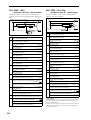
0–1A
5–1A
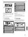
5–1A: Swap LFO 1&2
This command exchanges the settings of LFO1 and 2. If LFO2
has been selected as Frequency Modulation AMS1 or 2 of
LFO1, that setting will be cancelled for LFO2 after the LFO1
and 2 settings have been exchanged. If this is selected from
the OSC1 LFO1 or OSC1 LFO2 tab, the LFO1 and LFO2 of
OSC1 will be exchanged.
1 Select this command to open the dialog box.
2 Press the OK button.
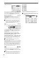
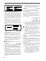
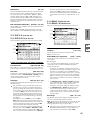
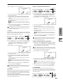
5–2: OSC1 LFO2
5–1a
Here you can make settings for the OSC1 LFO2, which is the
second LFO that can be applied to oscillator 1. (☞“5–1: OSC1
LFO1”) However in “Frequency Modulation” (5–1b), the
LFO cannot be selected as a modulation source in “AMS1” or
“AMS2.”
5–1b
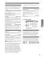
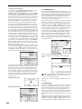
Parameter
number
▼ 5–1: Page Menu Command
5–1c
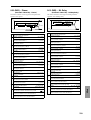
5–3: OSC2 LFO1
5–1a: OSC1 LFO1
Parameter
name
Waveform
[Triangle 0…Random6 (Vector)]
Select the LFO waveform.
Range of possible
parameter values
This can be used when “Oscillator Mode” (1–1a) is set to
Double.
Here you can make settings for the OSC2 LFO1, which is the
first LFO that can be applied to oscillator 2. (☞“5–1: OSC1
LFO1”)
iii
Table of Contents
3–6: Filter2 Mod.
Keyboard tracking and controller settings
to modulate the filter 2 cutoff frequency
.................................................................... 21
3–7: Filter2 LFO Mod. Filter 2 LFO settings to modulate the filter
2 cutoff frequency .................................... 21
1. Program mode. . . . . . . . . . . . . 1
3–8: Filter2 EG
Filter 2 EG settings ................................... 21
Program P4: Edit–Amp.................................. 21
Make amp settings for oscillators 1 and 2.
Program P0: Play ......................................... 1
Select and play programs.
4–1: Amp1 Level/Pan
Oscillator 1 volume and pan settings .... 21
4–2: Amp1 Mod.
Keyboard tracking and controller settings
to modulate amp 1 ................................... 22
4–3: Amp1 EG
Amp 1 EG settings ................................... 23
4–4: Amp2 Level/Pan
Oscillator 2 volume and pan settings .... 24
4–5: Amp2 Mod.
Keyboard tracking and controller settings
to modulate amp 2 ................................... 24
4–6: Amp2 EG
Amp 2 EG settings ................................... 24
Program P5: Edit–Common LFO ....................... 25
0–1: Perf. Edit
Select and play programs; use the
Performance Editor for simple editing ... 1
Make settings for the general purpose LFOs used to cyclically modulate the pitch, filter, and amp of oscillators 1
and 2.
0–2: Arpeggio
Arpeggio pattern selection and settings . 3
5–1: OSC1 LFO1
OSC1 LFO1 (for oscillator 1) settings .... 25
0–3: Sampling
Perform sampling; make settings for
audio inputs etc.......................................... 4
5–2: OSC1 LFO2
OSC1 LFO2 (for oscillator 1) settings .... 26
5–3: OSC2 LFO1
OSC2 LFO1 (for oscillator 2) settings .... 26
5–4: OSC2 LFO2
OSC2 LFO2 (for oscillator 2) settings .... 26
Program P1: Edit–Basic .................................. 7
Make basic oscillator settings and scale settings etc.
1–1: Program Basic
Oscillator settings for Single/Double/
Drums, Poly/Mono, scale etc................... 7
1–2: OSC Basic
Specify the multisample for oscillators 1
and 2 ............................................................ 9
1–3: Velo. Zone
1–4: Controller
Program P7: Edit–Arpeggiator ......................... 26
Make settings for the arpeggiator.
7–1: Arpeg. Setup
Select an arpeggio pattern and make
settings....................................................... 26
7–2: Scan Zone
Velocity zone settings ............................. 11
Specify the note and velocity ranges that
will operate the arpeggiator ................... 28
[SW1] and [SW2] key functions;
REALTIME CONTROLS [1]–[4] knob Bmode functions ........................................ 12
Program P8: Edit–Insert Effect......................... 28
Program P2: Edit–Pitch ................................. 12
Specify the oscillator output bus, and make insert effect
settings.
8–1: Routing
Specify the oscillator output bus and set
the send levels to the master effects ...... 28
Make pitch-related settings for oscillators 1 and 2.
2–1: OSC1 P.Mod
Specify oscillator 1 pitch modulation via
key position or controllers ...................... 12
8–2: Insert FX
Select insert effects and turn them on/off,
and make chain settings .......................... 29
2–2: OSC2 P.Mod
Specify oscillator 2 pitch modulation via
key position or controllers ...................... 14
8–3: IFX 1
Parameter settings for IFX1 .................... 30
8–4: IFX 2
Parameter settings for IFX2 .................... 30
8–5: IFX 3
Parameter settings for IFX3 .................... 30
8–6: IFX 4
Parameter settings for IFX4 .................... 30
8–7: IFX 5
Parameter settings for IFX5 .................... 30
2–3: Pitch EG
Pitch EG settings ...................................... 14
Program P3: Edit–Filter ................................. 16
Make filter settings for oscillators 1 and 2.
3–1: Filter1
Filter 1 (for oscillator 1) type, cutoff
frequency, and resonance settings ........ 16
3–2: Filter1 Mod.
Keyboard tracking and controller settings
to modulate the filter 1 cutoff frequency
.................................................................... 17
3–3: Filter1 LFO Mod. Filter 1 LFO settings to modulate the filter
1 cutoff frequency .................................... 18
iv
3–4: Filter1 EG
Filter 1 EG settings ................................... 19
3–5: Filter2
Filter 2 (for oscillator 2) type, cutoff
frequency, and resonance settings ........ 21
Program P9: Edit–Master Effect ....................... 31
Make master effect and master EQ settings.
9–1: Master FX
Select master effects and turn them on/
off, and make chain settings ................... 31
9–2: MFX 1
Parameter settings for MFX1 .................. 32
9–3: MFX 2
Parameter settings for MFX2 .................. 32
9–4: Master EQ
Parameter settings for master EQ .......... 32
Program
Combination P7: Edit–Arp...............................44
Make settings for arpeggiators A and B.
7–1: Setup
Assign arpeggiators to each timbre .......44
7–2: Arpegg. A
Select an arpeggio pattern and make
settings for arpeggiator A .......................45
7–3: Arpegg. B
Select an arpeggio pattern and make
settings for arpeggiator B ........................45
7–4: Scan Zone
Specify the ranges of notes and velocities
that will operate the arpeggiator ............45
Combination
2. Combination mode. . . . . . . . . 33
Combination P8: Edit–Insert FX........................46
Specify the output bus and master effect
send levels for each timbre ......................46
8–2: Insert FX
Select insert effects, turn them on/off, and
make chain settings ..................................47
0–1: Prog. Select
Select a program for each timbre ........... 33
0–2: Mixer
Specify pan and level ............................... 35
0–3: Arpegg. A
Select an arpeggio pattern and make
settings for arpeggiator A ....................... 36
8–3: IFX 1
Parameter settings for IFX1 .....................47
8–4: IFX 2
Parameter settings for IFX2 .....................47
Select an arpeggio pattern and make
settings for arpeggiator B ........................ 36
8–5: IFX 3
Parameter settings for IFX3 .....................47
8–6: IFX 4
Parameter settings for IFX4 .....................47
Perform sampling; make audio input
settings etc. ................................................ 36
8–7: IFX 5
Parameter settings for IFX5 .....................47
0–4: Arpegg. B
0–5: Sampling
Combination P1: Edit–Program/Mixer................ 37
Select the program for each timbre, and specify pan and
level.
1–1: Program/Mixer
Specify program, pan, and level of each
timbre ........................................................ 37
Combination P2: Edit–Trk Param ..................... 38
Sampling
8–1: Routing
Select and play combinations.
Combination P9: Edit–Master FX ......................48
Make settings for the master effects and master EQ.
9–1: Master FX
Select the master effects, turn them on/
off, and make chain settings ...................48
9–2: MFX 1
Parameter settings for MFX1 ..................48
9–3: MFX 2
Parameter settings for MFX2 ..................48
9–4: Master EQ
Parameter settings for master EQ ..........48
Song Play
Combination P0: Play ................................... 33
Sequencer
Specify the output bus for each timbre, and make insert
effect settings.
2–1: MIDI Channel
Specify MIDI channel and status for each
timbre ........................................................ 38
2–2: OSC
Make settings such as mono/poly and
portamento for each timbre .................... 38
2–3: Pitch
Make pitch-related settings such as
transpose and bend range for each timbre
.................................................................... 39
2–4: Other
Make delay and scale settings for each
timbre ........................................................ 40
Global
Set various parameters for each timbre.
Combination P3: Edit–MIDI Filter ..................... 40
3–2: MIDI 2
Joystick, ribbon controller ....................... 41
3–3: MIDI 3
Realtime control knobs ............................ 41
3–4: MIDI 4
SW1/2, foot controller etc. ...................... 41
Combination P4: Edit–Zone/Ctrl ....................... 42
Specify the key range and controllers for each timbre.
4–1: Key Z
Specify the key zone sounded by each
timbre ........................................................ 42
4–2: Vel Z
Specify the range of velocities sounded by
each timbre................................................ 42
4–3: MOSS Setup
Displayed if the EXB-MOSS option is
installed; set EXB-MOSS parameters ..... 43
4–4: Controller
Specify the function of the [SW1] and
[SW2] keys, and B-mode functions of the
REALTIME CONTROLS [1]–[4] knobs . 43
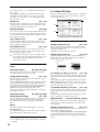
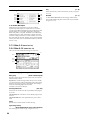
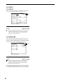
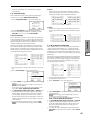
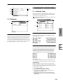
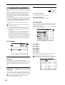
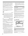
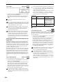
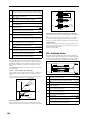
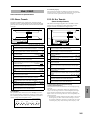
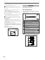
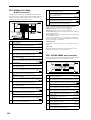
About the Jump pages
The LCD screens shown here are the Jump pages for each
mode.
The Jump page is a page menu that lets you access the various pages within each mode.
Here’s how to access the Jump page, and select the desired
page.
Effect
Program changes, aftertouch etc. ........... 40
• Press the [MENU] key to access the Jump page. In the
LCD screen, press the page that you want to select, or
press the numeric key [0]–[9] corresponding to the
number of the desired page. (☞BG p.16)
• Alternatively, you can hold down the [MENU] key and
press the numeric key [0]–[9] corresponding to the
number of the desired page.
Appendices
3–1: MIDI 1
Disk
Specify MIDI message reception filtering for each timbre.
v
3. Sequencer mode . . . . . . . . . . 49
Sequencer P4: Zone/Ctrl................................ 66
Specify the note range and controllers for each track.
4–1: Key Z 1–8
4–2: Key Z 9–16
.................................................................... 66
4–3: Vel Z 1–8
Specify the range of velocities sounded by
each track .................................................. 67
4–4: Vel Z 9–16
.................................................................... 67
4–5: MOSS 1–8
Displayed if the EXB-MOSS option is
installed; set EXB-MOSS parameters ..... 67
4–6: MOSS 9–16
.................................................................... 67
4–7: Controller
Sequencer P0: Play/Rec ................................ 49
Specify the function of the [SW1] and
[SW2] keys, and B-mode functions of the
REALTIME CONTROLS [1]–[4] knobs . 67
Make settings for playing/recording a song, and select the
program etc. used for each track.
Sequencer P5: Track Edit ............................... 68
0–1: Prog. 1–8
Program selection, mute, and solo settings
for each track ............................................ 49
0–2: Prog. 9–16
.................................................................... 49
Perform track editing and step recording.
5–1: Track Edit
Track editing operations such as Copy or
Delete, and step recording ...................... 68
5–2: Track Name
Edit the name of each track .................... 75
0–3: Mixer 1–8
Pan and volume settings for each track 55
0–4: Mixer 9–16
.................................................................... 55
0–5: PlyLoop 1–8
Loop track settings for each track .......... 55
0–6: PlyLoop 9–16
.................................................................... 55
Record and edit patterns, and make RPPR settings.
0–7: Sampling
Settings for sampling and audio input etc.
.................................................................... 56
6–1: Pattern Edit
Record a pattern, and perform pattern
editing such as Copy or Delete .............. 76
0–8: Preference
Select the realtime recording method, and
you can make metronome settings ........ 57
6–2: Pattern Name
Edit the name of a pattern....................... 78
6–3: RPPR Setup
RPPR settings............................................ 79
Sequencer P1: Cue List ................................. 59
Create and play a cue list for playing a succession of songs.
1–1: Cue List
Create and play back a cue list............... 59
Sequencer P2: Trk Param............................... 62
Sequencer P6: Pattern/RPPR .......................... 76
Sequencer P7: Arpeggiator............................. 81
Make settings for arpeggiators A and B.
7–1: Setup 1–8
Assign an arpeggiator to each track ...... 81
7–2: Setup 9–16
.................................................................... 81
7–3: Arpegg. A
Select an arpeggio pattern and make
settings for arpeggiator A ....................... 82
Set various parameters for each timbre.
2–1: MIDI Ch 1–8
MIDI channel and status settings for each
track ........................................................... 62
7–4: Arpegg. B
Select an arpeggio pattern and make
settings for arpeggiator B ........................ 82
2–2: MIDI Ch 9–16
.................................................................... 62
7–5: Scan Zone
2–3: OSC 1–8
Mono/poly and portamento settings etc.
for each track ............................................ 63
Specify the range of notes and velocities
that will operate the arpeggiator ........... 82
Sequencer P8: Insert Effect ............................ 83
2–4: OSC 9–16
.................................................................... 63
2–5: Pitch 1–8
Pitch-related settings (transpose, pitch
bend range etc.) for each track ............... 63
Specify the bus for the output of each track, and make
insert effect settings.
2–6: Pitch 9–16
.................................................................... 63
8–1: Routing 1–8
2–7: Other 1–8
Delay and scale settings for each track . 64
2–8: Other 9–16
.................................................................... 64
Sequencer P3: MIDI Filter .............................. 65
Specify MIDI message reception filtering for each track.
3–1: MIDI 1 1–8
3–2: MIDI 1 9–16
3–3: MIDI 2 1–8
vi
Specify the range of keys sounded by each
track ........................................................... 66
Program changes, aftertouch etc. .......... 65
.................................................................... 65
Joystick, ribbon controller ...................... 65
3–4: MIDI 2 9–16
.................................................................... 65
3–5: MIDI 3 1–8
Realtime control knobs ........................... 65
3–6: MIDI 3 9–16
.................................................................... 65
3–7: MIDI 4 1–8
SW1/2, foot controller etc. ..................... 66
3–8: MIDI 4 9–16
.................................................................... 66
Specify the bus and master effect send
levels for the output of each track ......... 83
8–2: Routing 9–16
.................................................................... 83
8–3: Insert FX
Select insert effects and turn them on/off,
and make chain settings .......................... 84
8–4: IFX 1
Parameter settings for IFX1 .................... 85
8–5: IFX 2
Parameter settings for IFX2 .................... 85
8–6: IFX 3
Parameter settings for IFX3 .................... 85
8–7: IFX 4
Parameter settings for IFX4 .................... 85
8–8: IFX 5
Parameter settings for IFX5 .................... 85
Sequencer P9: Master Effect ........................... 85
Make master effect and master EQ settings.
9–1: Master FX
Select master effects and turn them on/
off, and make chain settings ................... 85
9–2: MFX 1
Parameter settings for MFX1 .................. 86
9–3: MFX 2
Parameter settings for MFX2 .................. 86
9–4: Master EQ
Parameter settings for master EQ .......... 86
Parameter settings for IFX3 ...................122
8–6: IFX 4
Parameter settings for IFX4 ...................122
8–7: IFX 5
Parameter settings for IFX5 ...................122
Program
8–5: IFX 3
Combination
4. Sampling mode . . . . . . . . . . . 87
Sequencer
5. Song Play mode . . . . . . . . . 123
Sampling P0: Recording ............................... 88
Make sample recording settings such as input level, and
basic settings for multisamples and samples.
0–2: Input/Setup
Audio input settings, and recording setup
.................................................................... 96
0–3: Preference
Settings for creating indexes ................... 98
0–4: Memory Status
View the amount of remaining sample
memory (RAM), and the remaining
number of multisamples and samples .. 99
Sampling P1: Sample Edit ............................ 100
Song Play P0: Prog/Mix ............................... 123
Select SMF data and play it back.
0–1: Prog. 1–8
1–1: Sample Edit
Edit sample data (waveform data) ...... 100
Select the program for each track .........123
0–2: Prog. 9–16
..................................................................123
0–3: Mixer 1–8
Set pan and volume for each track .......125
0–4: Mixer 9–16
..................................................................125
0–5: Preference
Settings for consecutive playback of SMF
data, and metronome settings ..............125
Edit sample data (waveform data), and perform editing
operations such as Copy and Rate Convert.
Sampling
Basic settings such as selecting a
multisample and sample, and adjusting
the final input level .................................. 88
Song Play
0–1: Recording
Song Play P1: Track ................................... 126
Specify the status and scale for each track.
Status and scale settings ........................126
1–2: Status 9–16
..................................................................126
1–3: MOSS 1–8
Displayed if the EXB-MOSS option is
installed; set EXB-MOSS parameters ...126
Loop playback settings and editing ..... 107
1–4: MOSS 9–16
..................................................................126
2–1: Loop Edit
Sampling P3: Multisample............................ 117
Edit a multisample. Assign samples, and specify zones
and original keys.
Song Play P2: Controller Setup ...................... 127
Make controller settings.
3–1: Multisample
Edit multisamples .................................. 117
3–2: Preference
Settings for creating indexes ................. 119
2–1: Controller Setup Specify the function of the [SW1] and [SW2]
keys, and B-mode functions of the
REALTIME CONTROLS [1]–[4] knobs ...127
Sampling P4: Controller Setup ....................... 119
Song Play P3: Select Directory/Jukebox............ 128
Make controller settings.
4–1: Controller Setup Specify the function of the [SW1] and [SW2]
keys, and B-mode functions of the
REALTIME CONTROLS [1]–[4] knobs ... 119
Global
1–1: Status 1–8
Specify the region of the sample that will be played, make
loop playback settings, and perform editing operations
such as Time Slice and Time Stretch.
Disk
Sampling P2: Loop Edit................................ 107
Select the directory that contains the SMF you want to
play. If “Jukebox” is checked, you can create a jukebox list.
3–1: Select Directory
Select the directory that contains the SMF
you want to play .....................................128
3–1: Jukebox
Create a jukebox list ...............................128
Sampling P5: Audio CD................................ 120
Play back an audio CD and rip ............ 120
Sampling P8: Insert Effect ............................ 122
Specify the bus for the sample output, and make insert
effect settings.
8–1: Routing
Specify the bus for the sample
output ...................................................... 122
8–2: Insert FX
Select insert effects, turn them on/off, and
make chain settings................................ 122
8–3: IFX 1
Parameter settings for IFX1 .................. 122
8–4: IFX 2
Parameter settings for IFX2 .................. 122
Effect
5–1: Audio CD
Song Play P7: Arpeggiator ............................ 129
Make settings for arpeggiators A and B.
7–1: Setup 1–8
Assign an arpeggiator to each track .....129
7–2: Setup 9–16
..................................................................129
7–3: Arpegg. A
Select an arpeggio pattern and make
settings for arpeggiator A .....................130
7–4: Arpegg. B
Select an arpeggio pattern and make
settings for arpeggiator B ......................130
7–5: Scan Zone
Specify the range of notes and velocities
that will operate the arpeggiator ..........130
Appendices
Play back an audio CD, and rip samples from an audio
CD.
vii
Song Play P8: Insert Effect ........................... 131
Specify the bus for the output of each track, and make
insert effect settings.
8–1: Routing 1–8
6. Global mode . . . . . . . . . . . . 135
Specify the bus and the master effect send
levels for the output of each
track ......................................................... 131
8–2: Routing 9–16
.................................................................. 131
8–3: Insert FX
Select insert effects, turn them on/off, and
make chain settings ............................... 132
8–4: IFX 1
Parameter settings for IFX1 .................. 132
8–5: IFX 2
Parameter settings for IFX2 .................. 132
8–6: IFX 3
Parameter settings for IFX3 .................. 132
8–7: IFX 4
Parameter settings for IFX4 .................. 132
8–8: IFX 5
Parameter settings for IFX5 .................. 132
Song Play P9: Master Effect .......................... 133
Make settings for the master effects and master EQ.
9–1: Master FX
Select the master effects, turn them on/
off, and make chain settings ................. 133
9–2: MFX1
Parameter settings for MFX1 ................ 133
9–3: MFX2
Parameter settings for MFX2 ................ 133
9–4: Master EQ
Parameter settings for master EQ ........ 133
Global P0: Basic Setup.................................135
Make basic settings that affect the entire TRITON STUDIO,
and make AUDIO INPUT settings for other than Sampling
mode. If the EXB-mLAN option is installed, make settings
for mLAN input/output.
0–1: Basic
Master tune, key transpose, effect global
switch, and auto arpeggiator on/off
settings..................................................... 135
0–2: System Preference Bank map, system lock, and memory
protect settings ....................................... 137
0–3: Input/Sampling
Audio input settings for other than
Sampling mode ...................................... 139
0–4: mLAN Output
Audio and MIDI output settings to an
external mLAN device (EXB-mLAN
option) ..................................................... 140
0–5: mLAN Input
Audio and MIDI input settings from an
external mLAN device (EXB-mLAN
option) ..................................................... 141
Global P1: MIDI .........................................142
Make MIDI settings for the entire TRITON STUDIO.
1–1: MIDI
Settings such as global MIDI channel,
MIDI clock, and MIDI filter .................. 142
Global P2: Controller...................................146
Make settings for the damper pedal and assignable foot
switch/pedal.
2–1: Controller
Damper pedal and assignable foot
switch/pedal settings ............................ 146
Global P3: User Scale..................................146
Create user octave scales and user all note scales.
3–1: User Scale
Create user scales ................................... 146
Global P4: Category Name ............................147
Assign names to categories.
4–1: Program Cat.
Specify program category names ......... 147
4–2: Comb Cat.
Specify combination category names .. 147
Global P5: Drum Kit ....................................148
Edit or create drum kits.
5–1: Sample Setup
Assign a drum sample to each key ...... 148
5–2: Voice/Mixer
Specify the bus and pan etc. for each key
.................................................................. 150
Global P6: User Arpeggio..............................151
Edit or create user arpeggio patterns.
viii
6–1: Pattern Setup
Specify the operation of the arpeggio
pattern ..................................................... 151
6–2: Pattern Edit
Input tones for each step ....................... 153
Program
7. Disk mode . . . . . . . . . . . . . . 155
8. Effect Guide. . . . . . . . . . . . . 177
Files, directories, and icons ........................................................... 155
0–1: Load
Load the selected file or directory into
internal memory ..................................... 156
Overview................................................. 177
0–2: Save
Save data from internal memory to
various media ......................................... 165
2. Dynamic modulation (Dmod) .........................................................177
0–3: Utility
Rename, copy, delete, or format the
selected disk or file ................................ 169
0–4: Make Audio CD
Create an audio CD ............................... 172
0–5: Play Audio CD
Play an audio CD ................................... 174
0–6: Media Info
View information about the selected
media ....................................................... 175
Combination
1. Effects in each mode .....................................................................177
3. Effect I/O ........................................................................................177
Insert Effects (IFX 1, 2, 3, 4, 5) ...................... 178
1. In/Out .............................................................................................178
2. Routing...........................................................................................179
3. Mixer ..............................................................................................181
Sequencer
4. Controlling the Insert Effects via MIDI............................................182
Master Effects (MFX1, 2) ............................. 182
1. In/Out .............................................................................................182
2. Routing...........................................................................................183
3. Mixer ..............................................................................................184
Sampling
4. Controlling the Master Effects via MIDI..........................................185
Master EQ ............................................... 185
Main Output ............................................. 185
Individual Outputs...................................... 185
Song Play
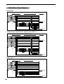
Effect/Mixer Block Diagram........................... 186
Program .............................................................................................186
Combination.......................................................................................186
Sampling............................................................................................186
Filter/Dynamic .......................................... 187
Filter and dynamics control effects
Global
000: No Effect ....................................................................................187
001: St. Amp Simulation (Stereo Amp Simulation) ............................187
002: Stereo Compressor....................................................................187
003: Stereo Limiter.............................................................................187
004: Multiband Limiter........................................................................188
005: Stereo Gate................................................................................189
006: OD/Hi.Gain Wah (Overdrive/Hi.Gain Wah) ................................189
Disk
007: St. Parametric 4EQ (Stereo Parametric 4-Band EQ) .................190
008: St. Graphic 7EQ (Stereo Graphic 7 Band EQ)...........................191
009: St. Wah/Auto Wah (Stereo Wah/Auto Wah)................................191
010: St. Random Filter (Stereo Random Filter)..................................192
011: St. Exciter/Enhncr (Stereo Exciter/Enhancer) ............................193
012: St. Sub Oscillator (Stereo Sub Oscillator) ..................................193
Effect
013: Talking Modulator .......................................................................194
014: Stereo Decimator .......................................................................195
015: St. Analog Record (Stereo Analog Record) ...............................195
Pitch/Phase Mod. ...................................... 196
Appendices
Pitch/phase modulation effects
016: Stereo Chorus............................................................................196
017: St. Harmonic Chorus (Stereo Harmonic Chorus) ......................196
018: Multitap Cho/Delay (Multitap Chorus/Delay)..............................197
019: Ensemble ...................................................................................197
020: Stereo Flanger ...........................................................................198
021: St. Random Flanger (Stereo Random Flanger) .........................198
ix
022: St. Env. Flanger (Stereo Envelope Flanger) .............................. 199
067: Comp – Cho/Flng (Compressor – Chorus/Flanger)................... 221
023: Stereo Phaser ........................................................................... 199
068: Comp – Phaser (Compressor – Phaser) ................................... 222
024: St. Random Phaser (Stereo Random Phaser) .......................... 200
069: Comp – Mt. Delay (Compressor – Multitap Delay) .................... 222
025: St. Env. Phaser (Stereo Envelope Phaser)................................ 200
070: Limiter – P4EQ (Limiter – Parametric 4-Band EQ) .................... 223
026: St. Biphase Mod. (Stereo Biphase Modulation)......................... 201
071: Limiter – Cho/Flng (Limiter – Chorus/Flanger) .......................... 223
027: Stereo Vibrato ........................................................................... 201
072: Limiter – Phaser ........................................................................ 224
028: St. Auto Fade Mod. (Stereo Auto Fade Modulation) .................. 202
073: Limiter – Mt. Delay (Limiter – Multitap Delay) ............................ 224
029: 2Voice Resonator ...................................................................... 202
074: Exciter – Comp (Exciter – Compressor) .................................... 225
030: Doppler...................................................................................... 203
075: Exciter – Limiter......................................................................... 225
031: Scratch ...................................................................................... 204
076: Exciter – Cho/Flng (Exciter – Chorus/Flanger).......................... 225
077: Exciter – Phaser ........................................................................ 226
Mod./P.Shift ............................................ 205
078: Exciter – Mt. Delay (Exciter – Multitap Delay)............................ 226
Other modulation and pitch shift effects
079: OD/HG – Amp Sim (Overdrive/Hi.Gain – Amp Simulation) ....... 227
032: Stereo Tremolo .......................................................................... 205
080: OD/HG – Cho/Flng (Overdrive/Hi.Gain – Chorus/Flanger) ....... 227
033: St. Env. Tremolo (Stereo Envelope Tremolo) ............................. 205
081: OD/HG – Phaser (Overdrive/Hi.Gain – Phaser) ........................ 228
034: Stereo Auto Pan ........................................................................ 206
082: OD/HG – Mt. Delay (Overdrive/Hi.Gain – Multitap Delay) ......... 228
035: St. Phaser + Trml (Stereo Phaser + Tremolo)............................ 206
083: Wah – Amp Sim (Wah/Auto Wah – Amp Simulation)................. 229
036: St. Ring Modulator (Stereo Ring Modulator) ............................. 207
084: Decimator – Amp (Decimator – Amp Simulation)...................... 229
037: Detune....................................................................................... 208
085: Decimator – Comp (Decimator – Compressor) ......................... 229
038: Pitch Shifter............................................................................... 208
086: Amp Sim – Tremolo (Amp Simulation – Tremolo) ...................... 230
039: Pitch Shift Mod. (Pitch Shift Modulation) ................................... 209
087: Cho/Flng – Mt. Dly (Chorus/Flanger – Multitap Delay) .............. 230
040: Rotary Speaker ......................................................................... 209
088: Phaser – Cho/Flng (Phaser – Chorus/Flanger) ......................... 231
089: Reverb – Gate ........................................................................... 231
ER/Delay................................................. 210
Early reflection and delay effects
Double Size ..............................................232
041: Early Reflections ....................................................................... 210
Double-size effects
042: Auto Reverse............................................................................. 211
090: Piano Body/Damper (Piano Body/Damper Simulation) ............. 232
043: L/C/R Delay ............................................................................... 211
091: St. Mltband Limiter (Stereo Multiband Limiter) .......................... 232
044: Stereo/Cross Delay ................................................................... 212
092: OD/HyperGain Wah (Overdrive/Hyper Gain Wah)..................... 232
045: St. Multitap Delay (Stereo Multitap Delay)................................. 212
093: Vocoder...................................................................................... 233
046: St. Modulation Delay (Stereo Modulation Delay)....................... 213
094: Multitap Cho/Delay (Multitap Chorus/Delay).............................. 234
047: St. Dynamic Delay (Stereo Dynamic Delay).............................. 213
095: St. Pitch Shifter (Stereo Pitch Shifter)........................................ 234
048: St. Auto Panning Dly (Stereo Auto Panning Delay) ................... 214
096: Rotary Speaker OD (Rotary Speaker Overdrive) ...................... 235
049: L/C/R BPM Delay ...................................................................... 214
097: Early Reflections........................................................................ 236
050: St. BPM Delay (Stereo BPM Delay) .......................................... 215
098: L/C/R Long Delay ...................................................................... 236
051: Sequence Delay ........................................................................ 215
099: St/Cross Long Dly (Stereo/Cross Long Delay) .......................... 236
100: LCR BPM Long Dly (L/C/R BPM Long Delay)........................... 237
Reverb ................................................... 216
Reverb effects
101: St. BPM Long Delay (Stereo BPM Long Delay)......................... 237
102: Hold Delay ................................................................................. 238
052: Reverb Hall................................................................................ 216
053: Reverb SmoothHall ................................................................... 216
Master EQ ................................................239
054: Reverb Wet Plate....................................................................... 216
Master EQ ......................................................................................... 239
055: Reverb Dry Plate ....................................................................... 216
056: Reverb Room ............................................................................ 217
057: Reverb BrightRoom................................................................... 217
Mono – Mono Chain ................................... 217
Effects that combine two mono effects connected in series
058: P4EQ – Exciter (Parametric 4-Band EQ – Exciter) ................... 217
059: P4EQ – Wah (Parametric 4-Band EQ – Wah/Auto Wah)........... 218
060: P4EQ – Cho/Flng (Parametric 4-Band EQ – Chorus/Flanger).. 218
061: P4EQ – Phaser (Parametric 4-Band EQ – Phaser) .................. 219
062: P4EQ – Mt. Delay (Parametric 4-Band EQ – Multitap Delay)..... 219
063: Comp – Wah (Compressor – Wah/Auto Wah) ........................... 220
064: Comp – Amp Sim (Compressor – Amp Simulation).................. 220
065: Comp – OD/HiGain (Compressor – Overdrive/Hi.Gain)............ 220
066: Comp – Param4EQ (Compressor – Parametric 4-Band EQ) ..... 221
x
Alternate Modulation Source (AMS)................. 241
About Alternate Modulation............................................................... 241
Program
9. Appendices . . . . . . . . . . . . . 241
Replacing the calendar battery..........................................................297
Connecting external SCSI devices................... 298
Packet writing support on the TRITON STUDIO .... 299
AMS (Alternate Modulation Source) List ........................................... 242
Combination
About Alternate Modulation Sources................................................. 241
EXB-DI option ........................................... 300
Alternate Modulation settings............................................................ 244
The effect of alternate modulation on various parameters, and example
applications ....................................................................................... 244
Index ..................................................... 302
Dynamic Modulation Source (Dmod)................ 246
Sequencer
Dynamic Modulation Source List....................................................... 247
About the BPM/MIDI SYNC function ................................................. 248
SW1/2 Assign ........................................... 249
SW1, SW2 Assign List ...................................................................... 249
Knob 1...4 B-Assign.................................... 250
Sampling
Realtime Control Knobs B–Assign List.............................................. 250
Foot Switch Assign ..................................... 251
Foot Switch Assign List ..................................................................... 251
Foot Pedal Assign ...................................... 252
Song Play
Foot Pedal Assign List....................................................................... 252
MIDI transmission when the TRITON STUDIO’s
controllers are operated............................... 253
TRITON STUDIO operations when control changes are
transmitted/received ................................... 255
Global
MIDI applications....................................... 258
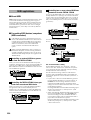
■ About MIDI .................................................................................... 258
■ Connecting MIDI devices/computers (MIDI connectors)............... 258
■ Messages transmitted and received by the TRITON STUDIO...... 259
TRITON STUDIO MIDI IMPLEMENTATION........... 269
Disk
Various messages...................................... 272
Data compatibility...................................... 279
Disk mode information ................................ 283
Chunks that are supported................................................................ 283
Effect
About KORG format files ................................................................... 284
Option boards/Memory/Calendar battery ........... 286
Please note when installing an option board/memory....................... 286
Cautions when installing the calendar battery................................... 286
About option boards/memory/calendar battery ................................. 287
Appendices
Checking after installation ................................................................. 287
Installing an EXB-PCM...................................................................... 288
Installing a DRAM SIMM ................................................................... 290
Installing the EXB-MOSS .................................................................. 291
Installing the EXB-DI ......................................................................... 292
Installing the EXB-mLAN................................................................... 293
Installing the CDRW-1 ....................................................................... 294
* Company names, product names, and names of formats
etc. are the trademarks or registered trademarks of their
respective owners.
xi
xii
Program
1. Program mode
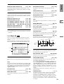
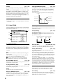
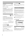
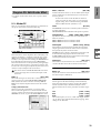
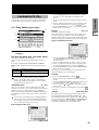
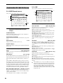
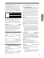
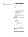
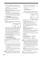
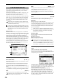
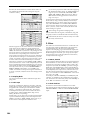
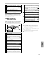
Program Select
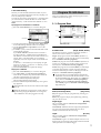
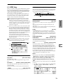
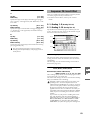
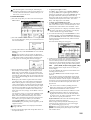
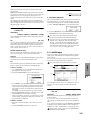
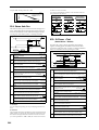
Program P0: Play
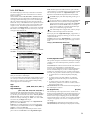
0–1: Perf. Edit (Performance Edit)
0–1
0–1a
P2
P1
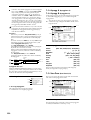
Here you can select a specific program. When this parameter
is selected, you can select programs using the [ ] [ ]
keys, numeric keys [0]–[9], or [VALUE] dial.
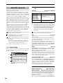
When you press the popup button, the “Bank/Program
Select” menu will appear. This displays programs by bank,
and allows you to select a program.
You can receive MIDI program changes from a connected external MIDI device, or use a foot switch to
select programs. (“Foot SW Assign” Global P2: 2–1a,
“Foot Switch Assign List” ☞p.251)
P3
All MIDI data in Program P0: Play is transmitted and
received on the Global MIDI Channel “MIDI Channel”
(Global P1: 1–1a).
P4
In this mode you can select and play programs.
P0
(INT-A...INT-F, EXB-A...EXB-G) 0...127,
(G, g(1)...g(9), g(d)) 1...128]
P5
Bank/Program Select menu:
P7
0–1b
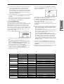
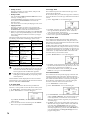
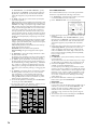
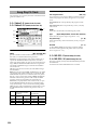
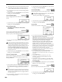
0–1a: Bank, Program Select, Category, 10’s Hold, Bank (Bank Select)
[INT-A...INT-F, G, g(1)...g(9), g(d), EXB-A...EXB-G]
This is the program bank display.
Use the BANK [INT-A]–[EXB-G] keys to select the bank.
Bank G will advance to the next G (or g) bank each time you
press the [INT-G] key, as shown.
G→g(1)→g(2)→g(3)→g(4)→g(5)→g(6)→g(7)→g(8)→g(9)→
g(d)→G
Bank INT-F can be selected if you have installed the
EXB-MOSS option. When installed, the 128 special
EXB-MOSS programs will be available.
The TRITON STUDIO provides rewritable banks INT-A–
INT-E and EXB-A–EXB-G, each containing 128 programs
(total 1,536). As non-rewritable program areas, it provides
banks G (basic programs for GM2), banks g(1)–g(9) (variation programs), and bank g(d) (drums). ☞A list of the factory-set programs is provided in the separate booklet
“VNL.”
INT-A...INT-D
for preloaded programs
INT-E
User programs, such as programs that use multisamples created in Sampling mode.
INT-F
for EXB-MOSS programs
G
GM2 basic program
g(1)–g(9)
GM2 variation programs*
g(d)
GM2 drums program
EXB-A...EXB-G
for user programs, and EXB-PCM series programs
* For banks with no variation sounds, the GM basic sounds
will be recalled. (An * will be added at the beginning of
the program name.)
P9
P8
0–1c
1 Press the popup button at the left of “Program Select” to
access the Bank/Program Select menu.
2 Press one of the tabs at left or right to select a specific
bank.
If you select the GM bank, the Variation button will be
enabled.
Each time you press the Variation button, the bank will
cycle in the order of G → g(1) → g(2) → ... → g(8) → g(9)
→ G.
3 Select a program from the list. You can press the list to
make a selection, or use the [ ] [ ] keys.
4 Press the OK button to execute, or press the Cancel button to cancel your selection.
Category
[00...15]
Selects the program category.
All programs are classified into one of sixteen categories.
You can select the desired category, and then choose programs from that category. Press the popup button, and the
“Category/Program Select” menu will appear.
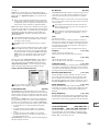
Category/Program Select menu:
1 Press the (category) popup button above “Program
Select” to access the Category/Program Select menu.
2 Press one of the tabs at left or right to select the desired
category.
3 Select a program from the list. You can press the list to
make a selection, or use the [ ] [ ] keys.
4 Press the OK button to execute, or press the Cancel button to cancel your selection.
The category setting of each program can be specified in the
“Write Program” (0–1A) dialog box.
1
10’s Hold
Pitch Stretch
1 Press the [./10’s HOLD] key to display
.
The 10’s place of the program number will be held
(fixed).
2 Now you can press any numeric key [0]–[9] to input the
1’s place of the program number with a single keystroke.
3 You can use the [ ] [ ] keys to change the value of the
10’s place.
4 To cancel, press the [./10’s HOLD] key to turn off the
display.
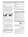
This simultaneously adjusts the Transpose and Tune of the
oscillator. This lets you produce a variety of tonal changes
and variations without loosing the character of the original
sound.
At the +00 setting, the value of the program parameters will
be unchanged.
An adjustment of +01 will lower the Transpose value by 1,
and simultaneously raise the Tune value by 100.
An adjustment of –01 will raise the Transpose value by 1,
and simultaneously lower the Tune value by 100.
However, it is not possible for the Transpose value to exceed
the range of ±12, nor the Tune value to exceed the range of
±1200.
(Tempo)
[040...240, EXT]
This sets the tempo of the arpeggiator. The tempo can also
be adjusted by the ARPEGGIATOR [TEMPO] knob.
A display of EXT indicates that the “MIDI Clock” (Global
P1: 1–1a) setting has been set to External MIDI or External
mLAN, and that the arpeggiator will synchronize to MIDI
Clock messages received from an external MIDI device.
0–1b: Program Information
This displays the functions that are assigned to the [SW1]
and [SW2] keys and to the B mode of REALTIME CONTROL knobs [1], [2], [3], [4], and the names of the effects that
are selected for the insertion effects and the master effects.
0–1c: Performance Editor
The Performance Editor lets you edit major program parameters without moving to the Program P1–P9 Edit pages.
This allows you to adjust multiple program parameters
within the currently selected program simultaneously, so
you can make broad adjustments quickly and easily.
You can use the Performance Editor when you wish to
adjust the depth of effects while you are playing, or to make
the initial rough settings to begin the process of creating a
new sound.
If you wish to keep the results of your editing, you must
write (save) the program (☞BG p.56).
Editing done using the Performance Editor will occur
within the range of the corresponding parameter. If
after using the Performance Editor to modify a value,
you move to another page or mode and then return, the
sound will remain in its edited state but the value
shown in the LCD screen by the Performance Editor
will be +00. You may do further editing from this state
if you wish.
Since editing done using the Performance Editor is not
as detailed as conventional editing, the balance
between parameters may be lost. If this occurs, use P1–
P9 Edit page to make fine adjustments.
If the “Enable Exclusive” (Global P1: 1–1b) setting is
checked, MIDI exclusive parameter changes will be
transmitted whenever you operate the Performance
Editor. If these messages are received by a TRITON
STUDIO whose “Enable Exclusive” setting is checked,
the Performance Editor corresponding to that message
will be modified.
Octave
[–03...+00...+03]
An adjustment of +01 will raise the pitch one octave.
An adjustment of –01 will lower the pitch one octave.
However, this setting cannot adjust the pitch higher than 4'
(feet) or lower than 32' (feet).
2
[–12...+00...+12]
This Performance Editor function cannot be used with
bank INT-F.
OSC Balance
[–10...0...+10]
This adjusts the level balance between oscillators 1 and 2.
At the +00 setting, the value of the program parameters will
be unchanged.
Positive (+) settings will lower the oscillator 2 level.
With an adjustment of +10, the oscillator 2 level will be 0.
The oscillator 1 level will not change.
Negative (–) settings will lower the oscillator 1 level.
With an adjustment of –10, the oscillator 1 level will be 0.
The oscillator 2 level will not change.
For programs whose “Oscillator Mode” (1–1a) setting
is Single, oscillator 2 will not sound. Only the level of
oscillator 1 will change. For a Drums program, this performance editor will have no effect.
Amp Level
[–10...0...+10]
This adjusts the amp level.
With an adjustment of +00, the value of the program parameters will be unchanged.
Positive (+) settings will increase the amp level above the
value that was set.
With an adjustment of +10, the amp level will be 127 (maximum).
Negative (–) settings will lower the amp level below the
value that was set.
With an adjustment of –10, the amp level will be 0.
Attack Time
[–10...0...+10]
This adjusts the attack times of the filter EG and amp EG.
With an adjustment of +00, the value of the program parameters will be unchanged.
Positive (+) settings will lengthen the attack times beyond
the values that were set.
With an adjustment of +10, the attack times will be 90.
Negative (–) settings will shorten the attack times.
With an adjustment of –10, the attack times will be 0.
When you modify “Attack Time,” the EG Start Level,
Attack Level, Start Level Modulation, and Attack Time
Modulation of the amp EG will also be adjusted simultaneously, to allow the maximum effect to be obtained.
Decay Time
[–10...0...+10]
This adjusts the Decay Time and Slope Time of the filter EG
and amp EG.
With an adjustment of +00, the value of the program parameters will be unchanged.
Positive (+) settings will lengthen the Decay Time and Slope
Time beyond the values that were set. With an adjustment of
+10, the times will be 99.
Negative (–) settings will shorten the Decay Time and Slope
Time. With an adjustment of –10, the times will be 0.
Program
P0
P1
P3
P2
It is not possible to write to banks G–g(d). If you have
edited a program from banks G–g(d) and wish to write
it, you must write to banks INT-A–INT-E or EXB-A–
EXB-G.
5 To execute the Write Program operation, press the OK
button. To cancel, press the Cancel button.
P4
[–10...0...+10]
This adjusts the master effect “Return 1” and “Return 2” (9–
1b) settings as a whole.
With an adjustment of +00, the value of the program parameters will be unchanged.
Positive (+) settings will raise the return levels above the
program setting.
With an adjustment of +10, the setting will be 127 (maximum).
Negative (–) settings will lower the return levels below the
program setting.
With an adjustment of –10, the setting will be 0.
You can also use the BANK [INT-A]–[EXB-G] keys to
select a bank.
You can also press the SEQUENCER [REC/WRITE] to
write a program in the same way as “Write Program.”
Press the SEQUENCER [REC/WRITE] key to access the
dialog box, and write the program. In this case, the settings will be written to the currently selected program.
P5
MFX Balance
With the factory settings, the program categories have
been given the names of instruments etc., but you can use
“Program Cat.” (Global P4: 4–1) to modify these category
names. The category selected here can be used to find
this program when selecting a program in Program,
Combination, Sequencer, or Song Play modes.
4 Press “To Program” to specify the writing destination.
P7
[–10...0...+10]
This adjusts the “Wet/Dry” setting of insert effects 1–5 as a
whole.
With an adjustment of +00, the value of the program parameters will be unchanged.
Positive (+) settings will raise the Wet levels above the program setting, and lower the Dry levels. With an adjustment
of +10, the setting will be “Wet.”
Negative (–) settings will lower the Wet levels below the
program setting, and raise the Dry levels. With an adjustment of –10, the setting will be “Dry.”
P8
IFX Balance
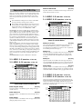
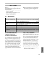
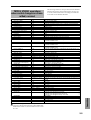
0–2: Arpeggio
Octave of OSC 1/2
Pitch Stretch
Transpose and Tune of OSC 1/2
OSC Balance
High Multisample, Low Multisample Level of OSC 1/2
Amp Level
Amp1 Level, Amp2 Level
Attack Time
Amp EG Attack Time, Start Level, Attack Level, Level
Modulation St, Time Modulation At of Amp 1/2, and
Filter EG Attack Time of Filter 1/2
Decay Time
AmpEG Decay Time, Slope Time of Amp 1/2; Filter
EG Decay Time and Slope Time of Filter 1/2
IFX Balance
Wet/Dry balance of the IFX1/2/3/4/5 effects
MFX Balance
Master Effect Return 1, 2
Arpeggiator parameters are edited in P7: Edit-Arpeggiator,
but major parameters can be edited here as well. When you
are playing in Program P0: Play, you can edit the arpeggiator in realtime, such as changing the arpeggio pattern etc.
To write (save) the results of your editing, use “Write Program” or “Update Program.” You can also use the [TEMPO],
[GATE], and [VELOCITY] knobs to edit the arpeggio in realtime (☞BG p.29, 30).
P9
Octave
0–1
0–1a
For the INT-F bank programs that can be used when
the EXB-MOSS option is installed, different program
parameters will be adjusted.
(☞EXB-MOSS owner’s manual)
0–2a
▼ 0–1: Page Menu Command
0–1A
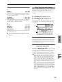
0–1A: Write Program
This command writes the edited program into the internal
memory.
If you wish to save a program, be sure to write it into memory. An edited program cannot be recovered if you do not
write it before turning off the power or selecting another
program.
1 Select “Write Program” to access the dialog box.
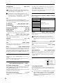
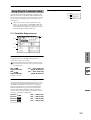
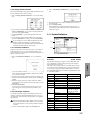
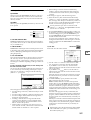
0–2a: Arpeggiator
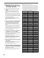
Pat (Pattern) [P000...P004, U000(I-A/B)...U506(User)]
Octave
[1, 2, 3, 4]
Reso (Resolution)
[ , , , , , ]
Sort
[Off, On]
Latch
[Off, On]
Key Sync.
[Off, On]
Keyboard
[Off, On]
Make settings for the program arpeggiator (☞P7: EditArpeggiator).
These parameters can also be set from P7: Edit-Arpeggiator.
2 The upper line shows the bank and program name.
If you wish to modify the program name, press the text
edit button to move to the text edit dialog box, and input
the desired program name.
3 In “Category,” specify the category of the program that
you are writing.
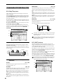
3
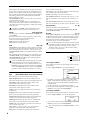
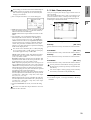
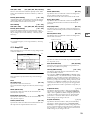
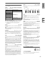
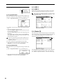
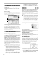
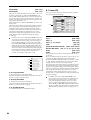
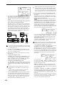
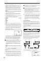
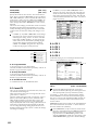
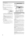
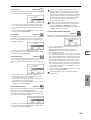
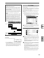
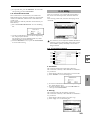
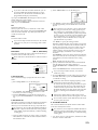
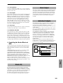
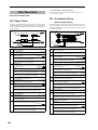
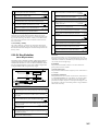
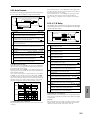
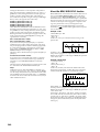
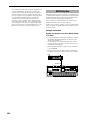
0–3: Sampling
Here you can adjust the settings for the analog/digital audio
signal input (AUDIO INPUT, S/P DIF, EXB-mLAN), and the
settings related to sampling in Program mode.
You can sample either an external audio signal, or a performance played on the TRITON STUDIO.
When sampling in Program mode, you can listen to the performance of the TRITON STUDIO’s arpeggiator etc. while
only sampling the external audio signal via the AUDIO
INPUT jacks or S/P DIF jacks; or you can resample while
you play a program using the TRITON STUDIO’s filters,
effects, and arpeggiator. You can also mix a performance on
the TRITON STUDIO with an external audio signal, and
sample the result. (☞BG p.45)
“Resampling” refers to the process of sampling an
external audio signal, processing this sampled wave
data in the digital domain using effects etc., playing it,
and then once again sampling the resulting performance.
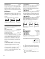
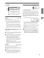
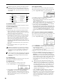
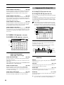
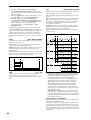
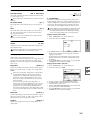
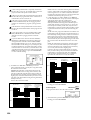
0–3
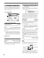
0–3a
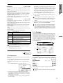
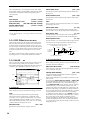
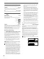
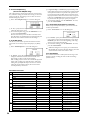
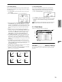
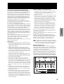
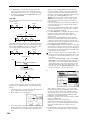
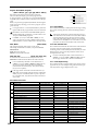
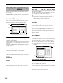
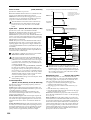
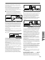
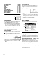
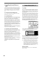
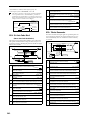
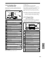
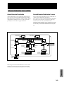
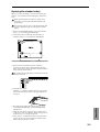
This lets you sample an external audio signal sent to buses 1,
2, 1/2 (specified by “Input” 0–3a), or the sounds sent to the
INDIVIDUAL 1, 2, 1/2 buses from a performance played on
the TRITON STUDIO from its keyboard or via MIDI input.
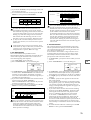
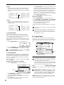
Normally when you want to sample a performance in Program mode, you will select L/R.
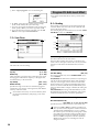
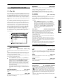
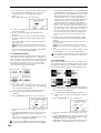
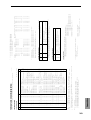
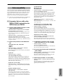
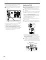
PROGRAM
Send
OSC / Filter / Amp
Master Effects Return
Insert Effects
AUDIO OUTPUT
L/MONO, R
Master EQ
ARPEGGIATOR
Source BUS
= L/R
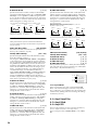
SAMPLING
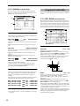
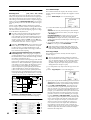
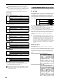
Select L/R if you want to mix a Program mode performance
(e.g., drum patterns played by the arpeggiator) with external audio from AUDIO INPUT (or S/P DIF or EXB-mLAN),
and sample them together. In this case, set Input “BUS (IFX/
Indiv.) Select” (0–3a) to L/R so that the external audio signal
will be sent to the L/R bus.
PROGRAM
Send
OSC / Filter / Amp
Master Effects Return
Insert Effects
AUDIO OUTPUT
L/MONO, R
Master EQ
ARPEGGIATOR
Source BUS
= L/R
SAMPLING
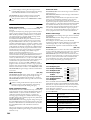
0–3b
AUDIO INPUT 1,2
"BUS(IFX/Indiv.) Select"
= L/R
(IFX1-5)
0–3c
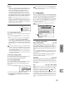
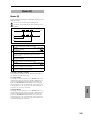
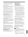
0–3a: Input (COMBI, PROG, SEQ, S.PLAY, DISK)
Input
[Analog, S/P DIF, mLAN]
Input1:
Input2:
Level
[0...127]
Pan
[L000...C064...R127]
BUS(IFX/Indiv.) Select
[L/R, IFX1…5, 1, 2, 3, 4, 1/2, 3/4, Off]
Send1(MFX1), Send2(MFX2)
[000...127]
Here you can specify the input source analog/digital audio
device, and set the input level, pan, bus, and master effect
sends.
These Input settings are valid in Combination, Program,
Sequencer, Song Play, and Disk modes. (☞Global P0: 0–
3a)
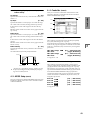
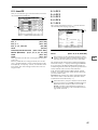
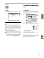
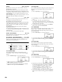
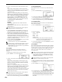
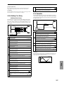
0–3b: Sampling Setup
Source BUS
[L/R, Indiv.1/2]
Selects the source that you want to sample. The sound being
sent to the bus selected here will be sampled.
L/R: The sound sent to the L/R bus will be sampled.
This lets you sample an external audio signal sent to the L/R
bus (specified by “Input” 0–3a), or the sounds sent to the L/
R bus from a performance played on the TRITON STUDIO
from its keyboard or via MIDI input.
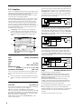
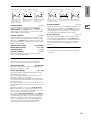
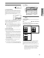
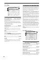
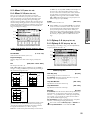
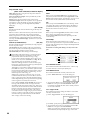
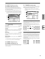
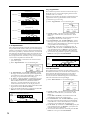
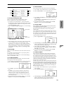
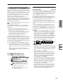
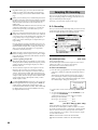
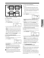
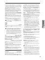
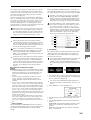
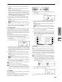
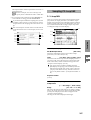
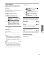
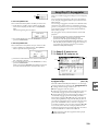
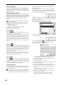
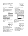
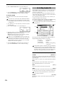
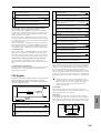
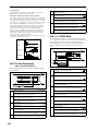
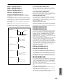
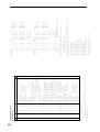
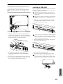
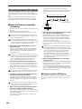
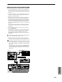
Indiv. 1/2: The sound sent to the INDIVIDUAL 1, 2, 1/2
buses will be sampled.
4
Select Indiv.1/2 if you want to monitor your playing in Program mode while sampling only an external audio signal
from AUDIO INPUT (or S/P DIF or EXB-mLAN). In this
case, set Input “BUS (IFX/Indiv.) Select” (0–3a) to 1, 2, or 1/2
so that the external audio signal will be sent to the INDIVIDUAL 1, 2, or 1/2 buses.
PROGRAM
Send
OSC / Filter / Amp
Insert Effects
Master Effects
Return
AUDIO OUTPUT
L/MONO, R
Master EQ
ARPEGGIATOR
Source BUS
= Indiv.1/2
AUDIO INPUT 1,2
Trigger
"BUS(IFX/Indiv.) Select"
= 1, 2, 1/2
(IFX1-5)
SAMPLING
AUDIO OUTPUT
INDIV.1, 2
[Sampling START SW, Note On]
This specifies how sampling will begin.
Sampling START SW: The TRITON STUDIO will enter
sampling-standby mode when you press the SAMPLING
[REC] key. Sampling will begin when you press the SAMPLING [START/STOP] key.
Note On: The TRITON STUDIO will enter samplingstandby mode when you press the SAMPLING [REC] key
and then press the SAMPLING [START/STOP] key. Sampling will begin when you play the keyboard.
Sampling will also begin if a MIDI note-on is received.
To stop sampling in either case, press the SAMPLING
[START/STOP] key once again. Alternatively, sampling will
stop automatically when the specified “Sample Time” is
reached.
For details on the procedure, refer to p.97.
Save to
[RAM, DISK]
Specifies the destination to which the data will be written
during sampling.
RAM: Sample into sample memory (RAM).
If you sample into sample memory (RAM), you will be able
to immediately hear the sample in Program mode or Sampling mode.
Settings for the writing destination RAM Bank and Sample
No., and settings for automatically converting the sample to
a program, are made by the page menu command “Select
Bank & Smpl No.” (0–3C).
If the sample is written into RAM, it will be lost when
the power is turned off, so you will need to save the
sample if you want to keep it.
DISK: Samples to the internal hard drive or to an external
hard drive connected to the SCSI connector.
A WAVE file will be created when you sample.
To listen to the sampled result, you can either load the sample into sample memory (RAM) in Disk mode, or use the
page menu command “Select Directory” (0–3D) etc. to select
the file and then press the SAMPLING [START/STOP] key.
Use the page menu command “Select Directory” to specify
the writing-destination drive, directory, and filename.
A single sample (WAVE file) loaded from hard disk into
sample memory (RAM) may not exceed 16 MB for
mono or 32 MB for stereo (however, sample memory
must be expanded to 32 MB or more).
It is not possible to sample directly to CD-R/RW. Also,
we do not recommend sampling to a removable disk.
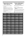
Mode (Sample Mode)
[L-Mono, R-Mono, Stereo]
Selects the channel(s) that will be sampled, to specify
whether the sample created will be mono or stereo.
The sound being sent to the internal L and/or R bus or the
internal Indiv.1 and/or 2 bus selected by the “Source BUS”
(0–3b) setting will be sampled.
L-Mono: The internal L channel or internal Indiv.1 channel
(as specified by “Source BUS”) will be sampled in mono.
R-Mono: The internal R channel or internal Indiv.2 channel
(as specified by “Source BUS”) will be sampled in mono.
Stereo: The internal L and R channels or internal Indiv.1
and 2 channels (as specified by “Source BUS”) will be sampled in stereo. This will create a stereo sample. (☞Sampling
P0: 0–1c)
Program
[min sec]
P4
P3
P2
P1
P0
Specifies the length of time that you want to sample. This
can be set in units of minutes and 0.001 second.
This parameter indicates amount of remaining memory in
the selected memory bank (the available sampling time). If
you sample in this state ([REC]→[START]→[STOP]), this
display will change automatically to indicate the remaining
time.
If you have enough free space in sample memory (RAM), it
is a good idea to set “Sample Time” generously, and then
after recording the sample, use the page menu command
“Truncate” (Sampling P1: 1–1A, P2: 2–1A) to delete the
unneeded portion, making the sample as compact as possible. You can also stop recording by pressing the SAMPLING
[START/STOP] key manually after the desired portion has
been sampled. (Sampling methods ☞BG p.45)
P5
If the writing-destination (“Save to”) is RAM, the maximum
value will be calculated from the amount remaining in the
selected Bank. (☞Sampling P0: 0–1c “Bank (RAM Bank)”)
If the writing-destination (“Save to”) is DISK, the maximum value will be calculated from the remaining capacity
of the disk specified by “Select Directory.” A maximum of 80
minutes can be sampled in one sample file for either mono
or stereo (monaural: approximately 440 MB, stereo: approximately 879 MB).
P7
The output destination and level of the metronome
sound are specified by the page menu command “Metronome Setup” (0–3A). If “BUS (Output) Select” is set
to L/R, the metronome will stop sounding the instant
sampling begins.
Sample Time
P8
[Off, 4, 8, 3, 6]
This specifies whether the metronome will sound a countdown when you begin sampling with the “Trigger” setting
Sampling START SW.
This can be set only if “Trigger” is set to Sampling START
SW.
Off: When you press the SAMPLING [START/STOP] key
from recording-standby mode, sampling will begin immediately.
4, 8, 3, 6: When you press the SAMPLING [START/STOP]
key from recording-standby mode, the specified number of
beats will be counted at the “ (Tempo)” (0–1a) tempo before
sampling will begin. If this is set to 4, sampling will begin on
the count of 0 after a count-down of 4–3–2–1–0.
If the writing-destination (“Save to”) is RAM, leaving
“Auto Optimize RAM” (Global P0: 0–3b) unchecked
will allow wasted space to increase, decreasing the
available sample memory (RAM). In this case, execute
the page menu command “Optimize RAM” to eliminate the wasted space.
The remaining amount of RAM can be checked in Sampling mode P0: Recording, Memory Status.
P9
Metronome Precount
The various Sampling Setup settings apply to the entire
Program mode, not just to an individual program.
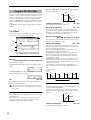
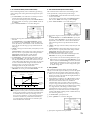
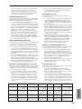
0–3c: Recording Level [dB]
ADC OVERLOAD !!
The “ADC OVERLOAD !!” indication will appear if the signal level from AUDIO INPUT 1, 2 is too high. In this case,
adjust the [LEVEL] knob or the output level of the external
audio source. (☞Sampling P0: 0–1d “Recording Level [dB]”)
Recording Level
[–inf, –72.0...0.0...+18.0 dB]
Adjusts the signal level at the final stage of sampling
(☞Sampling P0: 0–1d). Sample at the highest level that does
not make the level meter indicate CLIP.
Adjusting the “Recording Level” will not change the
sound that is output, but will affect the data that is
being sampled. This means that the sampled sound
may be distorted even if the sound you hear is not distorted.
This setting defaults to –12 dB when you turn on the power.
At a setting of –12 dB, CLIP will not appear even if you play
the program at its maximum level.
The “+12 dB” (Sampling P2: 2–1c) setting is applied to
samples that you recorded into sample memory (RAM)
when “Save to” (0–3b) is set to RAM. When “+12 dB” is
on, the playback level will increase by approximately
+12 dB.
If you check the “Auto +12 dB On” check box in the
page menu command “Select Bank & Smpl No.” (0–
3C), the “+12 dB” setting will automatically be turned
on during sampling.
5
The “Auto +12 dB On” setting will not affect samples
that you recorded to the internal hard disk etc. when
“Save to” (0–3b) is set to DISK. You can use “WAVE
File Play Level” (Global P0: 0-2a) to set the playback
level.
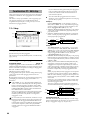
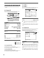
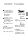
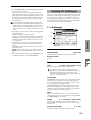
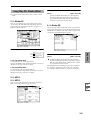
▼ 0–3: Page Menu Command
0–1A
0–1A
0–3A
0–3A
0–3B
0–3B
0–3C
0–3D
0–3A: Metronome Setup
Specifies the output destination and volume of the metronome that is sounded when you use “Trigger” Sampling
START SW to begin sampling.
1 Select “Metronome Setup” to access the dialog box.
2 In “BUS (Output) Select,” specify the output destination
of the metronome sound. If you select L/R, the metronome will stop as soon as sampling begins.
3 Set “Level” to specify the volume of the metronome.
4 Press the OK button to apply the settings you made, or
press the Cancel button to return to the state prior to
accessing this dialog box.
The metronome is valid only if “Trigger” is set to Sampling START SW.
0–3B: Optimize RAM
This command optimizes the sample memory (RAM).
When you execute this command, unused memory areas
will be reorganized, allowing the full amount of remaining
to be used.
If you run out of memory, try executing “Optimize RAM.”
The remaining amount of RAM can be checked in Sampling
mode P0: Recording, Memory Status.
1 Select “Optimize RAM” to access the dialog box.
2 In “Bank,” specify the sample memory (RAM) bank to
which the sampled data will be written.
3 In “Sample No.,” specify the writing-destination sample
number. By default, this will be the lowest-numbered
vacant sample number. If you select “----:----No Assign----”
or a sample number that already contains data, the data
will automatically be sampled into the lowest vacant
sample number. If you are sampling in stereo, specify
“Sample No.(L)” and “Sample No.(R).”
4 Set “Auto +12 dB On.”
On (checked): “+12 dB” (Sampling P2: 2–1c) will automatically be turned on for samples you record. Samples
for which “+12 dB” is on will play back approximately
+12 dB louder than if this setting were off.
When you resample a performance in Program, Combination, or Sequencer modes, you should normally set
“Recording Level” to about –12.0 (dB) so that the recording level will be as high as possible without clipping.
When you resample, the sound will be recorded at the
optimum level for sampled data, but the playback level
at playback will not be as loud as it was during the resampling process (if “+12 dB” (Sampling P2: 2–1c) is off). In
such cases, you can check the “Auto +12 dB On” check
box when you resample, so that “+12 dB” (Sampling P2:
2–1c) will automatically be on, making the sample play
back at the same level as when it was resampled.
In these modes, the power-on defaults are “Recording
Level” set to –12.0 (dB) and “Auto +12 dB On” turned on.
If you resample a performance in one of these modes
with these settings, the sample will play back at the same
level at which it was resampled.
If you want to monitor your performance in Program,
Combination, or Sequencer mode while sampling only
the external audio signal from AUDIO INPUT etc. (the
“Source BUS” Indiv.1/2 setting: 0–3b), we recommend
that you set “Recording Level” to about +0.0 (dB) and
turn off “Auto +12 dB On” when you resample.
The “Auto +12 dB On” setting is made independently
for Program, Combination, Sequencer, and Sampling
modes.
2 Press the OK button to execute the command, or press
the Cancel button to cancel without executing.
If “Auto Optimize RAM” (Global P0: 0–3b) is checked,
RAM will be optimized automatically.
0–3C: Select Bank & Smpl No.
Specifies the RAM bank and sample number into which the
sampled data will be written. You can also specify whether
the sample will automatically be converted to a program
after sampling. “Select Bank & Smpl No.” can be selected if
you have selected RAM as the “Save to” destination.
1 Select the “Select Bank & Smpl No.” to access the dialog
box.
6
5 “Convert to” specifies whether the sample will automatically be converted into a program as soon as it has been
sampled. This is convenient when you want to hear the
sound immediately after sampling.
If you check the “Program” check box, the sample will
automatically be converted into a program.
At the right, set “Program” and “MS” to specify the program number and multisample number for the converted program.
Set “Orig. Key” (Sampling P0: 0–1b) to specify the location of the original key. The multisample will create an
“Index” (Sampling P0: 0–1a) with this key as the “Top
Key” (Sampling P0: 0–1b). The “Orig. Key” will increment by one after sampling, and the next higher note will
be assigned the next time you sample.
6 Press the OK button to apply the settings you made, or
press the Cancel button to return to the state prior to
accessing this dialog box.
P0
Here you can make basic settings for the program, such as
oscillator mode and scale type.
1–1: Program Basic
P1
Specifying the save destination for a WAVE file
Program P1: Edit–Basic
1–1
1 Select the “Select Directory” to access the dialog box.
1–1b
P3
1–1a
P2
This lets you select the disk (internal hard disk, etc.) and
directory on which the WAVE file created by sampling will
be saved, and specify a filename.
You will also choose this “Select Directory” command when
you want to listen to a WAVE file that was saved on disk.
“Select Directory” can be selected when “Save to” is set to
DISK.
Program
0–3D: Select Directory
P4
1–1c
Playing back a WAVE file
1 Select the “Select Directory” to access the dialog box.
2 Use “Drive Select” and the Open and Up buttons to
select the drive and directory, and select the WAVE file
(44.1 kHz or 48 kHz) that you want to play.
3 Press the SAMPLING [START/STOP] key.
The selected WAVE file will be played.
4 Press the SAMPLING [START/STOP] key once again to
stop playback.
If the WAVE file is mono, the same sound will be output
to L/R.
While the WAVE file is playing back, sound cannot be
produced by playing the keyboard or receiving note
data at MIDI IN. Also, the arpeggiator will stop.
Oscillator Mode
P7
P8
1–1a: Oscillator Mode
[Single, Double, Drums]
Specifies the Program’s oscillator assignment; whether it
will use one or two oscillators, or a drum kit.
P9
2 Use the popup button located at the left of “Drive select”
to select the writing-destination drive for sampling.
3 Use the Open button and Up button to move to the
desired directory.
4 In “Name,” specify a name for the WAVE file that will be
written during sampling.
If you check “Take No.,” the file will be saved with a
two-digit “Take No.” added to the end of the filename.
This number will automatically increment each time you
sample. This is convenient when you are sampling
repeatedly, since each sample will be saved with its own
filename.
If “Take No.” is not checked, you can input up to eight
characters in “Name.” If “Take No.” is checked, you can
input up to six characters.
5 Press the Done button to complete the settings.
P5
Drive select
Single: The program will use one oscillator (Oscillator 1,
Filter 1, Amplifier 1). In this case the program will normally
have a maximum of 60-note polyphony.
Double: The program will use two oscillators (Oscillator 1/
2, Filter 1/2, Amplifier 1/2). In this case the program will
normally have a maximum of 30-note polyphony.
Drums: The program will use one oscillator (as when Single
is selected), but Oscillator 1 will be assigned a drum kit
instead of a multisample. In this case the program will normally have a maximum of 60-note polyphony.
If a program draws one multisample from the ROM
bank, and a second from either the Piano bank or one of
the installed EXB boards, then in this case, a Single program can have a maximum of 120-note polyphony, a
Double program a maximum of 60-note polyphony,
and a Drums program a maximum of 120-note polyphony. (☞BG p.15)
1–1b: Voice Assign Mode
Mode (Voice Assign Mode)
[Poly, Mono]
Poly: The program will play polyphonically, allowing you
play chords.
Mono: The program will play monophonically, producing
only one note at a time.
Single Trigger
[Off, On]
This is available when the “Mode (Voice Assign Mode)”
setting is set to Poly.
On (checked): When the same note is played repeatedly, the
previous note will be silenced before the next note is
sounded, so that the notes do not overlap.
Legato
[Off, On]
This is available when the “Mode (Voice Assign Mode)”
setting is set to Mono.
On (checked): Legato is on. When multiple note-on’s occur,
the first note-on will retrigger the sound, and the second and
subsequent note-on’s will not retrigger.
7
When legato is on, multiple note-on message will not retrigger the voice. If one note is already on and another note is
turned on, the oscillator sound, envelope, and LFO will not
be reset, and only the pitch of the oscillator will be updated.
This setting is effective for wind instrument sounds and
analog synth-type sounds.
Off (unchecked): Legato is off. Notes will always be retriggered when note-on occurs.
When legato is off, multiple note-on’s will retrigger the
voice at each note-on. The oscillator sound, envelope, and
LFO will be reset (and retriggered) according to the settings
of the program.
If “Legato” is checked, certain multisamples or keyboard locations may produce an incorrect pitch.
Priority
[Low, High, Last]
This parameter is valid when “Mode (Voice Assign Mode)”
is set to Mono.
It specifies which note will be given priority to play when
two or more notes are played simultaneously.
Low: Lowest note will take priority.
High: Highest note will take priority.
Last: Last note will take priority.
Hold
[On, Off]
On (checked): Hold is On. Even when you take your finger
off of the key, the note will continue sounding as if it continued to be held. Unless the Amp1 EG, Amp2 EG (4–3a, 4–6)
“Sustain (Sustain Level)” is set to 0, the sound will continue
playing.
This is ideal for playing drum programs, and when you set
“Oscillator Mode” (1–1a) to Drums, you should turn On.
Off (unchecked): Hold is Off. Except for drum programs,
you should normally set Off.
If you turn “Hold” On for a drum program, keys of the
selected drum kit whose “Enable Note Off Receive”
parameter (Global P5: 5–2a) is unchecked will be set to
Hold On. Keys that are checked will be set to Hold Off.
If you select Hold Off, the keys will be set to Hold Off
regardless of their “Enable Note Off Receive” setting.
octave consists of seven notes.
When “Key” is set to C, use the white keys. (The black keys
will sound the equal tempered pitches.)
Stretch: This tuning is used for acoustic pianos.
User All Notes Scale: This is the full-range scale (C–1 – G9)
that was specified in “User All Notes Scale” (Global P3: 3–
1b).
User Octave Scale 00–15: These are the single-octave scales
that were specified in “User Octave Scale” (Global P3: 3–1a).
Key (Scale Key)
[C…B]
Selects the tonic note of the specified scale.
This setting is not valid for Equal Temperament, Stretch,
and User All Notes Scale.
Random
[0…7]
As this value is increased, a greater variance will be applied
to the pitch when each note is sounded. Normally you will
set this to 0. This parameter is used when simulating instruments that have natural instability in pitch, such as tapemechanism organs or acoustic instruments.
If a scale other than Equal Temperament is selected, the
combination of the selected scale and the “Key” setting
may skew the tuning of the base key (for example
A=440 Hz). If this occurs, use “Master Tune” (Global
P0: 0–1a) to correct the pitch.
▼ 1–1: Page Menu Command
0–1A
1–1A
1–1B
1–1A: Copy Oscillator
This command is used to copy the settings from one oscillator to another.
1 Select “Copy Oscillator” to access the dialog box.
1–1c: Scale
Type
[Equal Temperament…User Octave Scale15]
Selects the basic scale for the internal tone generator.
Equal Temperament: This is the most widely used scale,
where each semitone step is spaced at equal pitch intervals.
Pure Major: In this temperament, major chords of the
selected tonic will be perfectly in tune.
Pure Minor: In this temperament, minor chords of the
selected tonic will be perfectly in tune.
Arabic: This scale includes the quarter-tone scale used in
Arabic music.
Pythagoras: This scale is based on ancient Greek musical
theory, and is especially effective for playing melodies.
2 In “From” specify the oscillator to copy, and in “Program” specify the bank and number of the copy source
program. You can use the Bank [INT-A]–[EXB-G] keys to
select the bank.
3 In “To,” specify the copy destination oscillator.
4 To execute the Copy Oscillator command, press the OK
button. To cancel, press the Cancel button.
1–1B: Swap Oscillator
This command exchanges the settings of oscillators 1 and 2.
1 Select “Swap Oscillator” to access the dialog box.
Werkmeister (Werkmeister III): This is an equal tempered
scale that was used since the later Baroque period.
Kirnberger (Kirnberger III): This scale was created in the
18th century, and is used mainly to tune harpsichords.
Slendro: This is an Indonesian gamelan scale in which an
octave consists of five notes.
When “Key” is set to C, use the C, D, F, G and A notes.
(Other keys will sound equal-tempered pitches.)
Pelog: This is an Indonesian gamelan scale in which an
8
2 To execute the Swap Oscillator command, press the OK
button. To cancel, press the Cancel button.
This can be selected only if “Oscillator Mode” (1–1a) is
Double.
Program
P0
The EXB* display will differ depending on the type of
option board.
P1
If a program that uses a multisample from an EXB-PCM
series board is selected, but the corresponding EXBPCM (expansion board) is not installed, the “High MS
Bank” field will indicate ROM. In this case, the program will not sound. By re-selecting the multisample
bank, you can make the program sound.
P2
The multisample(s) (waveform) or drum kit on which the
program will be based can be selected here for oscillator 1
and/or oscillator 2.
Internal ROM contains 429 (425: ROM + 4: Piano) different
multisamples (preset multisamples) and 153 drum kits. By
selecting a RAM multisample, you can use a multisample
that you created in Sampling mode or that you loaded in
Disk mode. If any of the EXB-PCM series options have been
installed, you will be able to select from among their multisamples as well. The following illustration shows a LCD
screen where “Oscillator Mode” (1–1a) has been set to Double. If this is set to Single, the OSC2 Multisample (1–2b) will
not appear and cannot be set.
EXB*: Multisamples from EXB-PCM series option boards
can be selected. “*” will indicate the type of installed option.
The multisample number for “High Multisample” will
depend on which EXB-PCM options have been installed.
P3
1–2: OSC Basic
Each multisample has an upper limit, and may not produce sound when played above that limit.
1–2
1–2b
P5
P7
1–2a
P4
When you press the “High Multisample” popup button, a
multisample list will appear, allowing you to select a multisample from the list.
If ROM is selected as the “High MS Bank,” you can select a
multisample from a tabbed list organized by type of instrument.
P8
Category/ROM Multisample Select menu:
P9
1–2c
The following illustration shows the display when “Oscillator Mode” (1–1a) has been set to Drums.
1–2
1–2d
S.Offset (High Start Offset)
[Off, On]
This specifies the point at which the multisample will begin
sounding. For some multisamples this parameter will have
no effect.
1–2a: OSC1 Multisample
Here you can select a multisample.
You can select different multisamples for High and Low, and
use velocity to switch between the two multisamples. Start
Offset, Reverse, and Level can be adjusted independently
for the High and Low multisamples.
High:
High MS Bank
[ROM, RAM, Piano, EXB*...]
High Multisample
[000...424, 000...999, 000...003, 000...]
Specifies the bank and multisample number of the High
multisample. The multisample you select here will sounded
by velocities greater than the value of the “Velocity M.Sample SW Lo→Hi” (1–2c) parameter “OSC1.” If you do not
wish to use velocity switching, set “OSC1” to a value of 001,
and select only the High multisample.
ROM: Selects a preset multisample. Use “High Multisample” to select from 000–424.
RAM: Selects a multisample that you created in Sampling
mode or that you loaded in Disk mode. Use “High Multisample” to select from 000–999.
Piano: You can select preset multisamples such as stereo
piano. Choose from 000–003 for the “High Multisample.”
On (checked): The sound will start from the start offset location that is pre-determined for each multisample.
However when a RAM bank is selected, this will depend on
the selected multisample. If you select a multisample that
includes one of the following types of sample, checking this
item will cause playback to start from the Loop Start Address.
• A sample that was recorded (sampled) in Sampling
mode
• A sample whose Loop Start Address was edited in
Sampling mode after the sample was loaded in Disk
mode
• A sample whose Loop Start Address was specified
automatically when it was loaded as an AKAI, AIFF, or
WAVE file in Disk mode
Off (unchecked): The sound will start from the beginning of
the multisample waveform.
Rev (High Reverse)
[Off, On]
The multisample will be played in reverse. In the case of
ROM or optional (EXB-PCM series) multisamples that were
originally specified to loop, or in the case of multisamples
that were set to loop in Sampling mode, the multisample
will be played back in “one-shot” reverse mode. If the multisample was originally set to reverse, it will playback without change.
On (checked): The multisample will playback in reverse.
Off (unchecked): The multisample will playback normally.
9
Lvl (High Level)
[000…127]
Specifies the level of the multisample.
Depending on the multisample, high settings of this
parameter may cause the sound to distort when a chord
is played. If this occurs, lower the level.
The playback level for a RAM multisample is also
affected by the “+12 dB” (Sampling P2: 2–1c) setting for
each sample. If the “+12 dB” setting is on, the playback
will be approximately +12 dB louder. (☞0–3C)
Low:
The High and Low multisamples selected for oscillator 2 in
“OSC 2 Multisample” (1–2b) will be switched at the velocity value that you specify here.
Notes played with a velocity stronger than this value will be
sounded by the High multisample.
1–2d: Drum Kit
Drum Kit [000(I-A/B)...143(User), 144(GM)...152(GM)]
Selects a drum kit.
000(I-A/B)–015(I-A/B)
Here you can assign the Low multisample for OSC1.
The multisample you select here will sounded by velocities
less than the value of the “Velocity M.Sample SW Lo→Hi”
(1–2c) parameter “OSC1.”
32(E-B)–47(E-B)
48(E-C)–63(E-C)
64(E-D)–79(E-D)
Low MS Bank
[ROM, RAM, Piano, EXB*...]
Low Multisample
[000...424, 000...999, 000...003, 000...]
S.Offset (Low Start Offset)
[Off, On]
Rev (Low Reverse)
[Off, On]
Lvl (Low Level)
[000…127]
☞For details on the “Low” parameters, refer to the explanations for the corresponding “High” parameters.
Octave
[–2[32’], –1[16’], +0[8’], +1[4’]]
Adjusts the pitch in octave units. The normal octave of the
multisample is pitched at 8' (feet).
Transpose
[–12…+12]
Adjusts the pitch in semitone steps over a range of ±1
octave.
Tune
[–1200…+1200]
Adjusts the pitch of the sample in one-cent steps (a semitone
is 100 cents) over a range of ±1 octave.
Delay
[0ms…5000ms, KeyOff]
Specifies a delay time from note-on until the note will sound.
With a setting of KeyOff, the sound will begin when note-off
occurs. This is used to create sounds such as the “click” that is
heard when a harpsichord note is released. In this case, set the
Amp1 EG, Amp2 EG (4–3a, 4–6) “Sustain” parameter to 0.
1–2b: OSC2 Multisample
This will appear when “Oscillator Mode” (1–1a) is set to
Double.
For details on the settings and function of the parameter,
refer to “1–2a: OSC1 Multisample.”
Preloaded drum kits
16(E-A)–31(E-A)
User drum kits
EXB-PCM series drum kits
80(E-E)–95(E-E)
96(E-F)–111(E-F)
112(E-G)–127(E-G)
128(User)–143(User)
User drum kits
(some preloaded drum kits)
144(GM)–152(GM)
ROM preset drum kits compatible with GM2
Octave
[–2[32’], –1[16’], +0[8’], +1[4’]]
Adjusts the pitch in octave units. When using a drum kit, set
the Octave to 8'.
When editing a drum program, you must set this
parameter to 8'. With other settings, the sounds of the
drum kit will be assigned to the wrong notes of the keyboard.
Transpose
[–12…+12]
This adjusts the location of the instruments in the selected
drum kit. Unless you need to change this, leave it at 0.
Tune
[–1200…+1200]
This adjusts the pitch in one-cent units.
The pitch of each drum kit can be adjusted in Global P5:
Drum kit.
Delay (Delay Time)
[0ms…5000ms, KeyOff]
This specifies a delay time from note-on until the sound will
begin.
With a setting of KeyOff, the sound will begin when noteoff occurs. In this case, set the Amp EG (4–3a) parameter
“Sustain” to 0.
▼ 1–2: Page Menu Command
0–1A
1–1A
1–2c: Velocity M.Sample SW Lo → Hi
(Velocity Multisample Switch Low → High)
OSC1 (OSC1 Velocity Switch)
[1…127]
The High and Low multisamples selected for oscillator 1 in
“OSC 1 Multisample” (1–2a) will be switched at the velocity value that you specify here.
Notes played with a velocity stronger than this value will be
sounded by the High multisample.
OSC2 (OSC2 Velocity Switch)
[1…127]
This will appear when “Oscillator Mode” (1–1a) is set to
Double.
10
1–1B
1–2A
1–2A: Sample Parameters
Specifies the sample for each index of a RAM multisample.
You can adjust the playback level, cutoff, resonance, pitch,
attack, and decay.
This can be selected if “Oscillator Mode” (1–1a) is Single or Double, and RAM is selected as the “High MS
Bank” or “Low MS Bank” for OSC1 Multisample or
OSC2 Multisample and “High Multisample” or “Low
Multisample” are selected.
Program
Here you can specify the velocity range at which each oscillator will sound.
The “Velocity M.Sample” SW Lo→Hi” (1–2c) setting in conjunction with these “OSC 1/2 Velocity Zone” settings will
determine the velocity ranges in which the High and Low
multisample or drum kit will sound.
P0
1 Select “Sample Parameters” to access the dialog box.
1–3: Velo. Zone (Velocity Zone)
P1
These settings are made for the selected multisample. If
another oscillator or program uses that multisample,
that oscillator or program will also be affected by the
changes you make here.
1–3
The volume is also affected by the “+12 dB” (Sampling
P2: 2–1c) setting. If the “+12 dB” setting is on, the playback will be approximately +12 dB louder.
Cutoff: Adjusts the filter cutoff. This adjustment will be
added to the value specified for “(Filter A) Frequency”
(3–1b, 3–5) of Filter 1 and 2.
Resonance: Adjusts the resonance level of the filter. This
adjustment will be added to the value specified for “(Filter A) Resonance” (3–1b, 3–5) of Filter 1 and 2.
Pitch: Adjusts the playback pitch in one-cent steps. A setting of +12.00 raises the pitch one octave, and a setting of
–12.00 will lower the pitch one octave. This parameter is
linked with the Sampling P3: Multi Sample parameter
“Pitch” (Sampling P3: 3–1b). The value that was specified
in Sampling mode will be displayed here.
Attack: Adjusts the attack times of the filter EG and amp
EG. This adjustment will be added to the “(Time) Attack”
of “Filter 1 EG,” “Filter 2 EG,” “Amp 1 EG,” and “Amp 2
EG” (3–4a, 3–8, 4–3a, 4–6).
Decay: Adjusts the decay times of the filter EG and amp
EG. This adjustment will be added to the “(Time) Decay”
of “Filter 1 EG,” “Filter 2 EG,” “Amp 1 EG,” and “Amp 2
EG” (3–4a, 3–8, 4–3a, 4–6).
4 Press the Done button to execute, and close the dialog
box.
P4
P5
P7
1–3a: OSC 1/2 Velocity Zone
[001...127]
P8
OSC1 Top
Sets the maximum velocity value that will sound oscillator
1.
OSC1 Bottom
P9
2 Index: Specify the index for which you wish to make settings. The number following “/” is the total number of
indexes in the selected multisample.
Sample: indicates the sample number and name for the
index.
3 For each index, you can make the following settings.
Level: Adjust the volume. Relative to the settings of
“Lvl” (1–2a) and “Amp Level” (4–1a, 4–4), negative (–)
values will decrease the levels, and positive (+) values
will increase the levels. A setting of +99 will double the
volume. This parameter is linked to the “Level” (Sampling P3: 3–1b). The value that was specified in Sampling
mode will be displayed here.
P3
P2
1–3a
[001...127]
Sets the minimum velocity value that will sound oscillator 1.
OSC2 Top
[001...127]
Sets the maximum velocity value that will sound oscillator
2.
OSC2 Bottom
[001...127]
Sets the minimum velocity value that will sound oscillator 2.
It is not possible to set the Bottom Velocity greater than
the Top Velocity, nor the Top Velocity less than the Bottom Velocity.
You can also input a value by playing a note on the keyboard while you hold down the [ENTER] key.
▼ 1–3: Page Menu Command
☞0–1A: Write Program, 1–1A: Copy Oscillator, 1–1B: Swap
Oscillator
Please be aware that the Compare function is not available for this command.
11
1–4: Controller (Controller Setup)
These settings specify the functions of the [SW1] key, the
[SW2] key, and the B-mode functions of REALTIME CONTROL knobs [1]–[4] in Program mode.
Program P2: Edit–Pitch
Here you can make pitch modulation settings for oscillators
1 and 2.
1–4
1–4a
2–1: OSC1 P.Mod (OSC1 Pitch Mod.)
These settings specify how key position (note number) will
affect the pitch of oscillator 1, and select the controllers that
will affect the oscillator 1 pitch and specify the depth of control. Here you can also specify the amount of pitch change
produced by the Pitch EG and by LFO1 and LFO2. You can
also switch portamento on/off and specify how it will apply.
1–4b
2–1
2–1a
1–4a: Panel Switch Assign
These settings assign functions to the [SW1] and [SW2] keys
(“SW1, SW2 Assign List” ☞p.249).
SW1 Assign
[Off, ..., After Touch Lock]
Assigns a function to the [SW1] key.
The on/off status of the switch is saved when the program is
written.
When you change the function, it will be reset to the “off”
state.
SW1 Mode
[Toggle, Momentary]
Specifies how the on/off state of the [SW1] key will change
when it is pressed.
Toggle: On/off will alternate each time the [SW1] key is
pressed.
Momentary: The function will be on only as long as the
[SW1] key remains pressed.
SW2 Assign
SW2 Mode
[Off, ..., After Touch Lock]
[Toggle, Momentary]
2–1b
2–1c
2–1d
2–1a: Pitch
Pitch Slope
[–1.0…+2.0]
Normally you will leave this at +1.0.
Positive (+) values will cause the pitch to rise as you play
higher on the keyboard, and negative (–) values will cause
the pitch to fall as you play higher on the keyboard.
With a value of 0, there will be no change in pitch, and the
C4 pitch will sound regardless of the key you play.
How the Pitch Slope and pitch are related
Pitch
+2
Assigns a function to the [SW2] key.
The functions that can be assigned to [SW2] key are the
same as for [SW1] key, except that SW2 Mod.:CC#81 is
available instead of SW1 Mod.:CC#80.
+1
2oct
1oct
1oct
0
1–4b: Realtime Control Knobs B–Assign
–1
C4 C5
Here you can assign functions (mainly various types of control change) to the B-mode of the REALTIME CONTROL
knobs [1]–[4] (“Realtime Control Knobs B–Assign List”
☞p.250).
The functions you set here will take effect when you operate
the REALTIME CONTROL knobs [1]–[4] in B-mode.
Knob 1–B (Knob 1–B Assign)
Knob 2–B (Knob 2–B Assign)
Knob 3–B (Knob 3–B Assign)
Knob 4–B (Knob 4–B Assign)
[Off, ..., MIDI CC#95]
[Off, ..., MIDI CC#95]
[Off, ..., MIDI CC#95]
[Off, ..., MIDI CC#95]
▼ 1–4: Page Menu Command
☞0–1A: Write Program, 1–1A: Copy Oscillator, 1–1B: Swap
Oscillator
12
Ribbon
Key
[–12…+12]
Specifies in semitone units how greatly the pitch will be
changed when you press the ribbon controller.
With a value of 12, the pitch can be changed a maximum of
one octave.
Positive (+) values will cause the pitch to rise when you
press the ribbon controller to the right of center, and negative (–) values will cause the pitch to fall.
For example with a setting of +12, pressing the far right edge
of the ribbon controller will raise the pitch one octave. With
a setting of –12, pressing the far right edge of the ribbon controller will lower the pitch one octave.
At the center of the ribbon controller, the original pitch will
remain, so you can use this in conjunction with pressing the
ribbon at its right edge to simulate the “hammering-on”
techniques used by guitarists.
[Off, (FEG, AEG, EXT)]
Selects the source that will modulate the pitch of oscillator 1
(“AMS List” ☞p.242).
Intensity (AMS Intensity)
[–12.00…+12.00]
Specifies the depth and direction of the effect produced by
“AMS (Pitch AMS).”
With a setting of 0, no modulation will be applied. With a
setting of 12.00, the pitch will change up to one octave.
For example if you set “AMS (Pitch AMS)” to After Touch
and apply pressure to the keyboard, the pitch will rise if this
parameter is set to a positive (+) value, or fall if this parameter is set to a negative (–) value. The range is a maximum of
one octave (☞p.244).
Intensity
[–12.00…+12.00]
Specifies the depth and direction of the modulation that the
pitch EG specified in P2: Edit-Pitch, Pitch EG page will
apply to the pitch.
With a setting of 12.00, the pitch will change a maximum of
±1 octave.
AMS (Pitch EG AMS)
[Off, (KT, EXT)]
Selects the source that will control the pitch modulation
applied by the pitch EG (“AMS List” ☞p.242).
Intensity (AMS Intensity)
[–12.00…+12.00]
Specifies the depth and direction of the effect that “AMS
(Pitch EG AMS)” will have.
For example if you set “AMS (Pitch EG AMS)” to Velocity
and set this value to 12.00, the velocity will control the range
of pitch change produced by the pitch EG in a range of ±1
octave (☞p.244). As you play more softly, the pitch change
will draw closer to the pitch EG levels.
Pitch change (level)
Note-on
Note-off
Fingered (Porta. Fingered)
Program
P0
P1
P3
On (checked): Portamento will be applied.
Off (unchecked): Portamento will not be applied.
[Off, On]
This parameter is available when “Enable (Porta. Enable)” is
checked.
On (checked): Portamento will be applied when you continue holding the previous note as you press the next note
(legato playing).
Off (unchecked): Portamento will always be applied,
regardless of how you play.
Time (Porta. Time)
[000...127]
This parameter is available when “Enable (Porta. Enable)” is
checked.
This sets the portamento time. Increasing the value will produce a slower change in pitch.
Note-on
Note-off
Note-off
LFO1:
LFO1 Intensity
[–12.00…+12.00]
Specifies the depth and direction of the pitch modulation
applied by the OSC 1 LFO1 settings you made in “OSC1
LFO1” (5–1).
With a setting of 12.00, a maximum of ±1 octave of pitch
modulation will be applied. Negative (–) values will invert
the LFO waveform.
JS+Y Int. (LFO1 JS+Y Int.)
Strongly played with
a positive (+) value
Strongly played with a
negative (–) value
“Intensity” and “AMS (Pitch EG AMS)” will be added
to determine the depth and direction of the pitch modulation applied by the pitch EG.
[–12.00…+12.00]
Specifies the depth and direction of the effect that joystick
movement in the +Y direction (away from yourself) will
have on the pitch modulation applied by the OSC1 LFO1.
As this value is increased, moving the joystick in the +Y
direction will cause the OSC1 LFO1 to produce deeper pitch
modulation. With a setting of 12.00 a maximum of ±1 octave
of pitch modulation will be applied. Negative (–) values
will invert the LFO waveform.
AMS (LFO1 AMS)
[Off, (PEG, FEG, AEG, KT, EXT)]
Selects the source that will control the depth of pitch modulation produced by the OSC1 LFO1 (“AMS List” ☞p.242).
Intensity (AMS Intensity)
Softly played
(Intensity setting)
P2
[Off, On]
2–1d: LFO1/2
2–1b: Pitch EG
Note-on
Enable (Porta. Enable)
P4
AMS (Pitch AMS)
Portamento will also be switched when CC#65 (Portamento SW) is received.
P5
[–60…+12]
Specifies in semitone units how the pitch will change when
the joystick is moved all the way to the left. A setting of 12
produces 1 octave of change.
For example if you set this to –60 and move the joystick all
the way to the left, the pitch will fall five octaves below the
original pitch. This can be used to simulate the downward
swoops that a guitarist produces using the tremolo arm.
This turns the portamento effect (smooth change in pitch
from one note to the next) on/off, and specifies how it will be
applied.
If [SW1] key or [SW2] key are set to Porta.SW:CC#65, turning
[SW1] key or [SW2] key on/off will apply portamento (“AMS
List” ☞p.242, “SW1, SW2 Assign List”, Porta.SW:#65).
P7
JS (–X)
2–1c: Portamento
P8
[–60…+12]
Specifies in semitone units how the pitch will change when
the joystick is moved all the way to the right. A setting of 12
produces 1 octave of change.
For example if you set this to +12 and move the joystick all
the way to the right, the pitch will rise one octave above the
original pitch.
P9
JS (+X)
[–12.00…+12.00]
Specifies the depth and direction of the effect that “AMS
(LFO1 AMS)” will have.
With a setting of 0, modulation will not be applied. With a
setting of 12.00, the OSC1 LFO1 will apply a maximum of ±1
octave of pitch modulation. Negative (–) settings will invert
the LFO waveform.
For example if “AMS (LFO1 AMS)” is set to After Touch and
you apply pressure to the keyboard, a positive (+) setting of
this parameter will cause the pitch modulation created by OSC1
LFO1 to be applied with the normal phase, and a negative (–)
setting will cause the LFO to be applied with inverted phase.
13
The “LFO1 Intensity,” “JS+Y (LFO1 JS+Y Int.)” and “AMS
(LFO1 AMS)” settings will be added to determine the depth
and direction of the pitch modulation applied by OSC1
LFO1 (☞p.244).
Attack (Attack Level)
[–99…+99]
Specifies the amount of pitch change when the attack time
has elapsed.
Release (Release Level)
LFO2:
LFO2 Intensity
[–12.00…+12.00]
JS+Y Int. (LFO2 JS+Y Int.)
[–12.00…+12.00]
AMS (LFO2 AMS)
[Off, (PEG, FEG, AEG, KT, EXT)]
Intensity (AMS Intensity)
[–12.00…+12.00]
[–99…+99]
Specifies the amount of pitch change when the release time
has elapsed.
Time:
These parameters specify the amount of time over which the
pitch change will occur.
Refer to the above “LFO1.”
Attack (Attack Time)
▼ 2–1: Page Menu Command
Specifies the time over which the pitch will change from
note-on until it reaches the pitch specified as the attack level.
☞0–1A: Write Program, 1–1A: Copy Oscillator, 1–1B: Swap
Oscillator
[0…99]
Decay (Decay Time)
[0…99]
Specifies the time over which the pitch will change after
reaching the attack level until it reaches the normal pitch.
Release (Release Time)
2–2: OSC2 P.Mod (OSC2 Pitch Mod.)
These settings specify how key position (note number) will
affect the pitch, and select the controllers that will affect the
oscillator 2 pitch and specify the depth of control. They also
specify the depth at which the pitch EG will affect the pitch of
oscillator 2, and the depth of pitch change produced by LFO1
and LFO2. Portamento on/off settings etc. are also found
here.
For details on the functions of these parameters, refer to the
preceding section “2–1: OSC1 P.Mod (OSC1 Pitch Mod.).”
[0…99]
Specifies the time over which the pitch will change from noteoff until it reaches the pitch specified as the release level.
Time-varying pitch settings (when Pitch EG Intensity = +12.00)
+99 = approximately 1 octave Attack Level
Note-off
Note-on
0 = pitch when
key is held
(sustained)
Start Level
Time
Release Level
Attack
Time
–99 = approximately 1 octave
Release Time
2–3: Pitch EG
2–3b: Level Modulation
Here you can make settings for the pitch EG, which creates
time-variant changes in the pitch of oscillators 1 and 2.
The depth of pitch change produced by these EG settings on
oscillator 1 (2) is adjusted by “Pitch EG” (2–1b, 2–2).
These settings allow the pitch EG Level parameters to be controlled by alternate modulation.
2–3
AMS1 (Level Mod. AMS1)
2–3a
2–3b
2–3c
2–3a: Pitch EG
These settings specify how the pitch will change over time.
Level:
These parameters specify the amount of pitch change.
The actual amount of pitch change will depend on the
“Pitch EG” (2–1b, 2–2) parameter “Intensity.” For example
with an “Intensity” setting of +12.00, a “Level” setting of
+99 would raise the pitch one octave, and a “Level” setting
of –99 would lower the pitch one octave.
Start (Start Level)
[–99…+99]
Specifies the amount of pitch change at note-on.
[Off, (KT, EXT)]
Selects the source that will control the pitch EG Level parameters (“AMS List” ☞p.242).
Intensity (AMS1 Intensity)
14
Decay
Time
[–99…+99]
Specifies the depth and direction of the effect applied by
“AMS1 (Level Mod. AMS1).”
With a setting of 0, the levels specified by “Pitch EG” (2–3a)
will be used.
For example if “AMS1 (Level Mod. AMS1)” is SW1:CC#80,
pressing the [SW1] key to turn it on will change the Level
parameters of the Pitch EG. (Set “Panel Switch Assign” (1–
4a) to SW1 Mod.CC#80.) As the absolute value of “Intensity
(AMS1 Intensity)” is increased, the pitch EG levels will
change more greatly when the [SW1] key is turned on. The
direction of the change is specified by “St (AMS1 SW Start)”
and “At (AMS1 SW Attack).” When the [SW1] key is turned
off, the pitch EG levels will return to their own settings.
If “AMS1 (Level Mod. AMS1)” is set to Velocity, increasing
the absolute value of “Intensity (AMS1 Intensity)” will produce increasingly wider change in pitch EG levels for
strongly-played notes. The direction of the change is specified by “St (AMS1 SW Start)” and “At (AMS1 SW Attack).”
As you play more softly, the pitch change will draw closer to
the pitch EG levels.
At (AMS SW Attack)
Program
[–, 0, +]
Specifies the direction of change in “Start (Start Level)”
caused by “AMS1 (Level Mod. AMS1).” If “Intensity
(AMS1 Intensity)” is a positive (+) value, a setting of + will
raise the EG level, and a setting of – will decrease it. With a
setting of 0 there will be no change.
Specifies the direction in which “AMS (Time Mod. AMS)” will
affect the “Attack (Attack Time).” With positive (+) values of
“Intensity (AMS Intensity),” a setting of + will cause the time
to be lengthened, and a setting of – will cause the time to be
shortened. With a setting of 0 there will be no change.
At (AMS1 SW Attack)
Dc (AMS SW Decay)
[–, 0, +]
[–, 0, +]
AMS2 (Level Mod. AMS2)
Intensity (AMS2 Intensity)
St (AMS2 SW Start)
At (AMS2 SW Attack)
▼ 2–3: Page Menu Command
[Off, (KT, EXT)]
[–99…+99]
[–, 0, +]
[–, 0, +]
Refer to the preceding paragraphs “AMS1 (Level Mod.
AMS1)”–“At (AMS1 SW Attack).”
P8
Specifies the direction of change in “Attack (Attack Level)”
caused by “AMS1 (Level Mod. AMS1).” If “Intensity (AMS1
Intensity)” is a positive (+) value, a setting of + will raise the
EG level, and a setting of – will decrease it. With a setting of
0 there will be no change.
Specifies the direction in which “AMS (Time Mod. AMS)”
will affect the “Decay (Decay Time).” With positive (+) values of “Intensity (AMS Intensity),” a setting of + will cause
the time to be lengthened, and a setting of – will cause the
time to be shortened. With a setting of 0 there will be no
change.
☞0–1A: Write Program, 1–1A: Copy Oscillator, 1–1B: Swap
Oscillator
2–3c: Time Modulation
These parameters let you use an alternate modulation
source to control the Time parameters of the pitch EG.
AMS (Time Mod. AMS)
[Off, (KT, EXT)]
Selects the source that will control the Time parameters of
the pitch EG (“AMS List” ☞p.242).
Intensity (AMS Intensity)
P0
A note played softly with “At” A note played strongly with A note played strongly with
set to + and “Dc” set to +
“At” set to + and “Dc” set to + “At” set to – and “Dc” set to –
(settings of 2–3a: Pitch EG)
P2
[–, 0, +]
Note-off
P3
St (AMS1 SW Start)
A note played strongly with
“St” set to 0, “At” set to –,
and SW1 turned on
Note-on
Note-off
P4
A note played strongly with
“St” set to 0, “At” set to +,
and SW1 turned on
Note-off
P5
A note played softly with
“St” set at 0, “At” set to +,
and SW1 turned on (the
settings of 2–3a: Pitch EG)
Note-off
P7
Note-off
Note-off
Note-on
Note-on
Note-on
P9
Note-on
Note-on
P1
Pitch EG changes (Time) (AMS = Velocity, Intensity = positive (+) value)
Pitch EG change (level) (AMS=SW1/Velocity, Intensity= positive (+) value
[–99…+99]
Specifies the depth and direction of the effect that “AMS
(Time Mod. AMS)” will have.
With a setting of 0, the pitch EG times will be just as specified by the “Pitch EG” (2–3a) settings.
The alternate modulation value at the moment that the EG
reaches each point will determine the actual value of the EG
time that comes next.
For example, the decay time will be determined by the alternate modulation value at the moment that the attack level is
reached.
When this parameter is set to values of 16, 33, 49, 66, 82, or
99, the specified EG times will speed up as much as 2, 4, 8,
16, 32, or 64 times respectively (or slowed down to 1/2, 1/4,
1/8, 1/16, 1/32, or 1/64 of the original time).
For example if “AMS (Time Mod. AMS)” is set to Velocity,
increasing the absolute value of “Intensity (AMS Intensity)”
will allow strongly-played notes to increase the changes in
pitch EG Time values. The direction of the change is specified by “At (AMS SW Attack)” and “Dc (AMS SW Decay).”
As you play more softly, the pitch EG times will more
closely approach the actual settings of the pitch EG.
15
When the “Filter Type” is Low Pass Resonance, the cutoff
will have a steeper slope.
Program P3: Edit–Filter
Low Pass
Here you can make settings for the filters that will be used by
oscillators 1 and 2. You can select either a 24 dB/octave low
pass filter with resonance, or a series connection of a 12 dB/
octave low pass filter and a 12 dB/octave high pass filter.
When “Oscillator Mode” (1–1a) is set to Single, filter 1 will
be used, and when it is set to Double, filters 1 and 2 will be
used.
When Single is selected, pages relating to filter 2 cannot be
selected.
Level
12dB/oct
24dB/oct
Frequency
Frequency (A Frequency)
[00…99]
Specifies the cutoff frequency of filter 1A.
Resonance (A Resonance)
3–1: Filter1
Here you can specify the basic filter type used by oscillator
1, and set the cutoff frequency and resonance.
3–1
[00…99]
This emphasizes the overtone components that lie in the
region of the cutoff frequency specified by “Frequency (A
Frequency),” producing a more distinctive sound. Increasing this value will produce a stronger effect.
Resonance Mod. by AMS
[Off, (PEG, FEG, AEG, LFO, KT, EXT)]
Selects the source that will control the “Resonance (A Resonance)” level (“AMS List” ☞p.242).
3–1a
Intensity (AMS Intensity)
3–1b
3–1c
3–1a: Filter Type
Filter Type
[Low Pass Resonance, Low Pass & High Pass]
Selects the type for filter 1.
Low Pass Resonance: 24 dB/octave low pass filter with resonance.
[–99…+99]
Specifies the depth and direction of the effect that “Resonance Mod. by AMS” will have on the resonance level specified by “Resonance (A Resonance).”
For example if Velocity has been selected, changes in keyboard velocity will affect the resonance.
With positive (+) values, the resonance will increase as you
play more strongly, and as you play more softly the resonance will approach the level specified by the “Resonance
(A Resonance)” setting.
With negative (–) values, the resonance will decrease as you
play more strongly, and as you play more softly the resonance will approach the level specified by the “Resonance
(A Resonance)” setting.
The resonance level is determined by adding the “Resonance (A Resonance)” and “Intensity (AMS Intensity)” values.
The effect of resonance
Low Pass & High Pass: 12 dB/octave low pass filter and 12
dB/octave high pass filter in series.
Trim
[00…99]
Adjusts the level at which the audio signal output from
oscillator 1 is input to filter 1A.
If the trim value is set too high, the sound may be distorted if Resonance is set to a high value or when you
play a chord.
3–1b: Filter A
Low Pass
Level
Low resonance value
High resonance value
3–1c: Filter B
This parameter will be displayed when “Filter Type” (3–1a)
is set to Low Pass & High Pass.
This filter cuts the low-frequency range that lies below the
cutoff frequency. By cutting the lower overtones, it lightens
the tone.
High Pass
This is a filter that cuts the high-frequency region above the
cutoff frequency.
This is the most common type of filter, and is used to cut
part of the overtone components, making an originally
bright timbre sound more mellow (darker).
Level
12dB/oct
Frequency
Frequency (B Frequency)
Specifies the cutoff frequency of filter 1B.
16
[00…99]
Here you can make settings to specify how keyboard tracking, controllers, and filter 1 EG intensity will control the Filter 1 cutoff frequency “Frequency” (A/B Frequency) to
modify the tone.
When “Filter Type” (3–1a) is Low Pass Resonance, parameters for filter B will not be displayed.
Program
P0
How cutoff frequency is affected by keyboard location and the Ramp
setting
(“Intensity to A” and “Intensity to B” = +50)
Cutoff frequency
P1
3–2: Filter1 Mod.
High Ramp=+99
P2
☞0–1A: Write Program, 1–1A: Copy Oscillator, 1–1B: Swap
Oscillator
increase the “Resonance (A Resonance)” (3–1b) will correspond to the keyboard location.
If you set “Ramp Low (KBDTrk Ramp Low)” to +43 and
“Ramp High (KBDTrk Ramp High)” to –43, the cutoff frequency will not be affected by keyboard location. Use this
setting when you do not want the cutoff frequency to
change for each note.
High Ramp=+62
High Ramp=0
High Ramp=–43
Low Ramp=+99
High Ramp=–99
Low Ramp=+43
3–2
P3
▼ 3–1: Page Menu Command
3–2a
Low Ramp=–62
Low Key
High Key
P4
Low Ramp=0
Key
3–2b
Intensity to A (KBDTrk Int. to A)
[–99…+99]
These settings specify keyboard tracking for the cutoff frequency of filter 1.
The way in which the cutoff frequency is affected by the
position of the key you play (note number) can be specified
by the “Key Low (KBDTrk Key Low),” “Key High (KBDTrk
Key High),” “Ramp Low (KBDTrk Ramp Low)” and “Ramp
High (KBDTrk Ramp High)” parameters.
Intensity to B (KBDTrk Int. to B)
3–2b: Filter EG
Velocity to A
Specifies the note number at which keyboard tracking will
begin to be applied, and set the “Intensity to A (KBDTrk Int.
to A)” and “Intensity to B (KBDTrk Int. to B)” parameters to
specify the depth and direction of the change applied to filter 1 A and B.
For the range of notes between “Key Low (KBDTrk Key
Low)” and “Key High (KBDTrk Key High),” the cutoff frequency will change according to the key position (pitch).
This parameter specifies the depth and direction of the effect
that velocity will have on the time-varying changes created
by the filter 1 EG (as set by “Filter 1 EG” 3–4) to control the
filter 1A cutoff frequency.
With positive (+) values, playing more strongly will cause
the filter 1 EG to produce greater changes in cutoff frequency. With negative (–) values, playing more strongly will
also cause the filter 1 EG to produce greater changes in cutoff frequency, but with the polarity of the EG inverted.
[C–1…G9]
Keyboard tracking will apply to the range below the specified note number.
Key High (KBDTrk Key High)
[C–1…G9]
Keyboard tracking will apply to the range above the specified note number.
P8
[–99…+99]
Specifies the depth and direction of the effect that keyboard
tracking will have on filter 1B (☞“Intensity to A (KBDTrk
Int. to A)”).
Key:
Note numbers can also be entered by holding down the
[ENTER] key while you press a note on the keyboard.
P9
3–2a: Keyboard Track
P7
Specifies the depth and direction of the effect that the keyboard tracking specified by “Key Low (KBDTrk Key Low),”
“Key High (KBDTrk Key High),” “Ramp Low (KBDTrk
Ramp Low)” and “Ramp High (KBDTrk Ramp High)” will
have on filter 1A.
With positive (+) values, the effect will be in the direction
specified by keyboard tracking, and with negative (–) values the effect will be in the opposite direction.
3–2c
Key Low (KBDTrk Key Low)
P5
Low Ramp=–99
[–99…+99]
Velocity to B
[–99…+99]
This parameter specifies the depth and direction of the effect
that velocity will have on the time-varying changes created
by the filter 1 EG to control the filter 1B cutoff frequency (☞
“Velocity to A”).
Changes in cutoff frequency
Note-on
Note-on
Note-on
Note-off
Note-off
Note-off
Ramp (Ramp Setting):
Specifies the angle of keyboard tracking.
Ramp Low (KBDTrk Ramp Low)
Ramp High (KBDTrk Ramp High)
[–99…+99]
[–99…+99]
If “Intensity to A (KBDTrk Int. to A)” and “Intensity to B
(KBDTrk Int. to B)” are set to +50, “Ramp Low (KBDTrk
Ramp Low)” is set to –62 and “Ramp High (KBDTrk Ramp
High)” is set to +62, the angle of the change in cutoff frequency will correspond to the keyboard location (pitch).
This means that the oscillation that occurs when you
Softly played
(The setting of 3–2b: Intensity to A)
Intensity to A
Strongly played
Setting to +
Strongly played
Setting to –
[–99…+99]
Specifies the depth and direction of the effect that the timevarying changes created by the filter 1 EG will have on the
filter 1A cutoff frequency.
With positive (+) settings, the sound will become brighter
when the EG levels set by Filter 1 EG Level and Time parame-
17
ters (3–4a) are in the “+” area, and darker when they are in
the “–” area.
With negative (–) settings, the sound will become darker
when the EG levels set by Filter 1 EG “Level” and “Time”
parameters (3–4a) are in the “+” area, and brighter when
they are in the “–” area.
Intensity to B
3–3
3–3a
[Off, (EXT)]
Selects the source that will control the depth and direction of
the effect that the time-varying changes produced by the filter 1 EG will have on the cutoff frequency of filters 1A and
1B (“AMS List” ☞p.242).
Int to A (AMS Int. to A)
Here you can use the filter 1 LFO to apply cyclic modulation
to the cutoff frequency of filter 1 (for oscillator 1) to create
cyclical changes in tone.
[–99…+99]
Specifies the depth and direction of the effect that the timevarying changes created by the filter 1 EG will have on the
filter 1B cutoff frequency (☞“Intensity to A”).
AMS (Filter EG AMS)
3–3: Filter1 LFO Mod.
3–3b
[–99…+99]
Specifies the depth and direction of the effect that “AMS
(Filter EG AMS)” will have on filter 1A. For details on how
this will apply (☞“Intensity to A”).
3–3a: LFO 1
Int to B (AMS Int. to B)
Specifies the depth and direction of the modulation that
OSC1 LFO1 (set by “OSC1 LFO1” 5–1) will have on the cutoff frequency of filter 1A.
Negative (–) settings will invert the phase.
[–99…+99]
Specifies the depth and direction of the effect that “AMS
(Filter EG AMS)” will have on filter 1B. For details on how
this will apply (☞“Intensity to A”).
The sum of the settings for “Velocity to A (B),” “Intensity to A (B),” and “Int to A (B) (AMS Int. to A/B)” will
determine the depth and direction of the effect produced by the filter EG.
Intensity to A (LFO1 Int. to A)
[–99…+99]
Intensity to B (LFO1 Int. to B)
[–99…+99]
Specifies the depth and direction of the modulation that
OSC1 LFO1 will have on the cutoff frequency of filter 1B
(☞“Intensity to A (LFO1 Int. to A)”).
Change in cutoff
3–2c: Filter A/B Modulation
Filter A:
AMS1 (Filter A AMS1)
[Off, (PEG, AEG, EXT)]
Selects the source that will control modulation of the filter
1A cutoff frequency (“AMS List” ☞p.242).
Intensity (A AMS1 Intensity)
[–99…+99]
Specifies the depth and direction of the effect that “AMS1
(Filter A AMS1)” will have.
When “AMS1 (Filter A AMS1)” is JS X, a positive (+) value
for this parameter will cause the cutoff frequency to rise
when the joystick is moved toward the right, and fall when
the joystick is moved toward the left. With a negative (–)
value for this parameter, the opposite will occur.
This value is added to the setting of the Filter A “Frequency
(A Frequency)” (3–1b).
AMS2 (Filter A AMS2)
Intensity (A AMS2 Intensity)
[Off, (PEG, AEG, EXT)]
[–99…+99]
Selects “AMS2 (Filter A AMS2),” and specify the depth and
direction of the effect that the selected source will have
(☞“AMS1 (Filter A AMS1),” “Intensity (A AMS1 Intensity)”).
Filter B:
This will be displayed when “Filter Type” (3–1a) is Low
Pass & High Pass.
Two alternate modulation sources can be used to modulate
the cutoff frequency of filter 1B (☞“Filter A”).
▼ 3–2: Page Menu Command
☞0–1A: Write Program, 1–1A: Copy Oscillator, 1–1B: Swap
Oscillator
18
Low setting
High setting
JS–Y Intensity to A (LFO1 JS–Y Int. to A)
[–99...+99]
The joystick can be moved in the –Y direction (toward yourself) to control OSC1 LFO1, modulating the cutoff frequency
of filter 1A.
This parameter specifies the depth and direction of control.
Higher settings of this parameter will cause OSC1 LFO1 to
have a greater effect on filter 1 when you move the joystick
in the –Y direction (toward yourself).
JS–Y Intensity to B (LFO1 JS–Y Int. to B)
[–99...+99]
The joystick can be moved in the –Y direction (toward yourself) to control OSC1 LFO1, modulating the cutoff frequency
of filter 1B.
This parameter specifies the depth and direction of control.
(☞”JS–Y Intensity to A (LFO1 JS–Y Int. to A)”)
AMS (LFO1 AMS)
[Off, (PEG, FEG, AEG, KT, EXT)]
Selects a source that will control the depth and direction of
cutoff frequency change for both filters 1A and 1B (“AMS
List” ☞p.242).
Intensity to A (LFO1 AMS Int. to A)
[–99…+99]
Specifies the depth and direction of the effect that “AMS
(LFO1 AMS)” will have on filter 1A.
For example if “AMS (LFO1 AMS)” is After Touch, higher
settings of this parameter will allow greater change to be
applied to OSC1 LFO1 when you apply pressure to the keyboard.
Break (Break Point Level)
Program
[–99…+99]
Specifies the depth and direction of the effect that “AMS
(LFO1 AMS)” will have on filter 1B (☞“Intensity to A (LFO1
AMS Int. to A)”).
[–99…+99]
Specifies the cutoff frequency after the decay time has
elapsed.
Sustain (Sustain Level)
[–99…+99]
P1
[–99…+99]
P2
Specifies the cutoff frequency that will occur when the
release time has elapsed.
Time:
These parameters specify the time over which each change
will occur.
Attack (Attack Time)
P3
Intensity to A (LFO2 Int. to A)
[–99…+99]
Intensity to B (LFO2 Int. to B)
[–99…+99]
JS–Y Intensity to A (LFO2 JS–Y Int. to A)
[–99…+99]
JS–Y Intensity to B (LFO2 JS–Y Int. to B)
[–99…+99]
AMS (LFO2 AMS)
[Off, (PEG, FEG, AEG, KT, EXT)]
Intensity to A (LFO2 AMS Int. to A)
[–99…+99]
Intensity to B (LFO2 AMS Int. to B)
[–99…+99]
Release (Release Level)
[00…99]
P4
Adjusts the depth of the cyclic modulation applied by OSC1
LFO2 (set by 5–2) to the cutoff frequency of filters 1A and 1B
(☞LFO 1: 3–3a).
Specifies the time over which the level will change from
note-on until the attack level is reached.
Decay (Decay Time)
P5
3–3b: LFO 2
P0
Specifies the cutoff frequency that will be maintained from
after the slope time has elapsed until note-off occurs.
[00…99]
☞0–1A: Write Program, 1–1A: Copy Oscillator, 1–1B: Swap
Oscillator
Slope (Slope Time)
3–4: Filter1 EG
Release (Release Time)
Here you can make settings for the EG that will produce
time-varying changes in the cutoff frequency of filters 1A
and 1B.
The depth of the effect that these settings will have on the
filter 1 cutoff frequency is determined by Filter EG (3–2b).
3–4
[00…99]
P8
▼ 3–3: Page Menu Command
P7
Specifies the time over which the level will change from the
attack level to the break point level.
Specifies the time over which the level will change after the
decay time has elapsed until the sustain level is reached.
P9
Intensity to B (LFO1 AMS Int. to B)
[00…99]
Specifies the time over which the level will change after
note-on occurs until the release level is reached.
Attack Level
Note-off
Sustain Level
Note-on
The specified
cutoff
frequency
Release
Level
Break
Point
Level
Start
Level
Attack
Time
Decay
Time
Time
Slope
Time
Release
Time
3–4a
3–4b: Level Modulation
3–4b
3–4c
These settings let you use alternate modulation to control
the Level parameters of the filter 1 EG.
AMS (Level Mod. AMS)
3–4a: Filter1 EG
Intensity (AMS Intensity)
Specifies the time-varying change produced by the filter 1
EG.
Level:
The result will depend on the filter that was selected in “Filter Type” (3–1a). For example with the Low Pass Resonance
filter, positive (+) values of EG Intensity will cause the tone
to be brightened by positive (+) levels, and darkened by
negative (–) levels.
Start (Start Level)
[–99…+99]
Specifies the cutoff frequency at the time of note-on.
Attack (Attack Level)
[Off, (KT, EXT)]
Selects the source that will control the Level parameters of
the filter 1 EG (“AMS List” ☞p.242).
[–99…+99]
Specifies the cutoff frequency after the attack time has
elapsed.
[–99…+99]
Specifies the depth and direction of the effect that “AMS
(Level Mod. AMS)” will have.
For example if “AMS (Level Mod. AMS)” is Velocity, and
you set “St (AMS SW Start),” “At (AMS SW Attack)” and
“Br (AMS SW Break)” to + and set “Intensity (AMS Intensity)” to a positive (+) value, the EG levels will rise as you
play more strongly. If “Intensity (AMS Intensity)” is set to a
negative (–) values, the EG levels will fall as you play more
strongly.
With a setting of 0, the levels specified by “Filter 1 EG” (3–
4a) will be used.
St (AMS SW Start)
[–, 0, +]
Specifies the direction in which “AMS (Level Mod. AMS)”
will affect “Start (Start Level).” When “Intensity (AMS
Intensity)” has a positive (+) value, a setting of + for this
parameter will allow “AMS (Level Mod. AMS)” to raise the
EG level, and a setting of – will allow “AMS (Level Mod.
AMS)” to lower the EG level. With a setting of 0 there will be
no change.
19
At (AMS SW Attack)
[–, 0, +]
Specifies the direction in which “AMS (Level Mod. AMS)”
will affect “Attack (Attack Level).” When “Intensity (AMS
Intensity)” has a positive (+) value, a setting of + for this
parameter will allow “AMS (Level Mod. AMS)” to raise the
EG level, and a setting of – will allow “AMS (Level Mod.
AMS)” to lower the EG level. With a setting of 0 there will be
no change.
Br (AMS SW Break)
[–, 0, +]
Specifies the direction in which “AMS (Level Mod. AMS)”
will affect “Break (Break Point Level).” When “Intensity
(AMS Intensity)” has a positive (+) value, a setting of + for
this parameter will allow “AMS (Level Mod. AMS)” to raise
the EG level, and a setting of – will allow “AMS (Level Mod.
AMS)” to lower the EG level. With a setting of 0 there will be
no change.
Filter 1 EG changes (level) (AMS = Velocity, Intensity = a positive (+) value)
Note-on
Note-on
Note-off
Note-on
Note-off
Softly played note with “St,” Strongly played note with
“At,” and “Br” set to + (setting “St,” “At,” and “Br” set to +
of 3–4a: Filter 1 EG)
Note-off
Strongly played note with
“St,” “At,” and “Br” set to –
Dc (AMS1 SW Decay)
[–, 0, +]
Specifies the direction in which “AMS1 (Time Mod. AMS1)”
will affect the decay time. With positive (+) values of
“Intensity (AMS1 Intensity),” setting this parameter to +
will allow AMS1 to lengthen the time, and setting this
parameter to – will allow AMS1 to shorten the time. With a
setting of 0 there will be no change.
Sl (AMS1 SW Slope)
[–, 0, +]
Specifies the direction in which “AMS1 (Time Mod. AMS1)”
will affect the slope time. With positive (+) values of “Intensity (AMS1 Intensity),” setting this parameter to + will
allow AMS1 to lengthen the time, and setting this parameter
to – will allow AMS1 to shorten the time. With a setting of 0
there will be no change.
Rl (AMS1 SW Release)
[–, 0, +]
Specifies the direction in which “AMS1 (Time Mod. AMS1)”
will affect the release time. With positive (+) values of
“Intensity (AMS1 Intensity),” setting this parameter to +
will allow AMS1 to lengthen the time, and setting this
parameter to – will allow AMS1 to shorten the time. With a
setting of 0 there will be no change.
Filter 1 EG changes (Time) (AMS = Velocity, Intensity = a positive (+) value)
Note-on
Note-on
Note-off
Note-on
Note-off
Note-off
3–4c: Time Modulation
These settings let you use alternate modulation to control
the Time parameters of the filter 1 EG.
AMS1:
AMS1 (Time Mod. AMS1)
[Off, (KT, EXT)]
Selects the source that will control the Time parameters of
the filter 1 EG (“AMS List” ☞p.242).
Intensity (AMS1 Intensity)
[–99…+99]
Specifies the depth and direction of the effect that “AMS1
(Time Mod. AMS1)” will have.
For example if “AMS1 (Time Mod. AMS1)” is set to Flt KTr
+/+, the EG Time parameters will be controlled by the Keyboard Track (3–2a) settings. With positive (+) values of this
parameter, positive (+) values of Ramp (Ramp Setting) will
lengthen the EG times, and negative (–) values of Ramp
(Ramp Setting) will shorten the EG times. The direction of
change is specified by “At (AMS1 SW Attack),” “Dc (AMS1
SW Decay),” “Sl (AMS1 SW Slope),” and “Rl (AMS1 SW
Release).”
With a setting of 0, the times specified by Filter 1 EG (3–4a)
will be used.
If “AMS1 (Time Mod. AMS1)” is set to Velocity, positive
(+) values of this parameter will cause EG times to lengthen
as you play more strongly, and negative (–) values will
cause EG times to shorten as you play more strongly.
At (AMS1 SW Attack)
[–, 0, +]
Specifies the direction in which “AMS1 (Time Mod. AMS1)”
will affect the attack time. With positive (+) values of
“Intensity (AMS1 Intensity),” setting this parameter to +
will allow AMS1 to lengthen the time, and setting this
parameter to – will allow AMS1 to shorten the time. With a
setting of 0 there will be no change.
Softly played note with “At,” Strongly played note with
“At,” “Dc,” “Sl” and “Rl” set
“Dc,” “Sl” and “Rl” set to +
(setting of 3–4a: Filter 1 EG) to +
AMS2:
AMS2 (Time Mod. AMS2)
Intensity (AMS2 Intensity)
At (AMS2 SW Attack)
Dc (AMS2 SW Decay)
Sl (AMS2 SW Slope)
Rl (AMS2 SW Release)
Strongly played note with
“At,” “Dc,” “Sl” and “Rl” set
to –
[Off, (KT, EXT)]
[–99…+99]
[–, 0, +]
[–, 0, +]
[–, 0, +]
[–, 0, +]
These parameters are the settings for AMS2 to control the
Time parameters of the filter 1 EG (☞AMS1).
▼ 3–4: Page Menu Command
0–1A
1–1A
1–1B
3–4A
3–4A: Sync Both EGs
When you select the page menu command “Sync Both
EGs,” a check mark will be added at the left of “Sync Both
EGs.” In this state, you can edit the filter 1 EG and filter 2 EG
simultaneously. (Editing either EG will change the settings
of both EGs.)
“Sync Both EGs” cannot separately sync the filter EG
and amp EG. For example if they are synced in 4–3A,
they will also be synced here.
This can be selected only if “Oscillator Mode” (1–1a) is
Double.
20
Program
P0
Make settings for amp 1 which controls the volume of oscillator 1, and amp 2 which controls the volume of oscillator 2.
Pan settings are also made here.
P1
4–1
P2
4–1a
P5
P4
P3
4–1b
P7
4–1: Amp1 Level/Pan
These parameters control the volume and pan of oscillator 1.
P8
Make settings for filter 2 which controls the sound of oscillator 2. You can choose either a 24 dB/octave low pass filter
with resonance or a 12 dB/octave low pass filter and 12 dB/
octave high pass filter connected in series. Filter 2 can be
used if “Oscillator Mode” (1–1a) is Double. (☞”3–1:
Filter1” – “3–4: Filter1 EG”)
Program P4: Edit–Amp
4–1a: Amp Level
Amp Level (Amp1 Level)
P9
3–5: Filter2
3–6: Filter2 Mod.
3–7: Filter2 LFO Mod.
3–8: Filter2 EG
[0…127]
Sets the volume of oscillator 1.
The volume of a program can be controlled by CC#7
(volume) and #11 (expression). The resulting level is
determined by multiplying the values of CC#7 and #11.
The Global MIDI channel “MIDI Channel” (Global P1:
1–1a) is used for control.
4–1b: Pan
Pan (Amp1 Pan)
[Random, L001…C064…R127]
Sets the pan (stereo location) of oscillator 1.
A setting of L001 places the sound at far left, C064 in the
center, and R127 to far right.
Random: The sound will be heard from a different location
at each note-on.
This can be controlled by CC#10 (panpot). A CC#10
value of 0 or 1 will place the sound at the far left, a
value of 64 will place the sound at the location specified
by the “Pan” setting for each oscillator, and a value of
127 will place the sound at the far right. This is controlled on the global MIDI channel “MIDI Channel”
(Global P1: 1–1a).
Use DKit Setting
[Off, On]
This option is availble only when “Oscillator Mode” (1–1a)
is set to Drums.
On (checked): The sound will be output at the “Pan” setting
that has been made for each key of the drum kit (Global P5:
5–2b). When “Oscillator Mode” is Drums, you will normally use this setting.
Off (unchecked): All keys of the Drum Kit will use the “Pan
(Amp 1 Pan)” setting.
AMS (Pan AMS)
[Off, (PEG, FEG, AEG, LFO, KT, EXT)]
Selects the source that will modify pan (“AMS List”
☞p.242). This change will be relative to the “Pan (Amp1
Pan)” setting.
21
Intensity
[–99…+99]
Specifies the depth of the effect produced by “AMS (Pan
AMS).”
For example if “Pan (Amp1 Pan)” is set to C064 and “AMS
(Pan AMS)” is Note Number, positive (+) values of this
parameter will cause the sound to move toward the right as
the note numbers increase beyond the C4 note (i.e., as you
play higher), and toward the left as the note numbers
decrease (i.e., as you play lower). Negative (–) values of this
parameter will have the opposite effect.
Ramp High (KBDTrk Ramp High)
[–99…+99]
With positive (+) values of this parameter, the volume will
increase as you play notes above the “Key High (KBDTrk
Key High)” note number. With negative (–) values, the volume will decrease.
Volume change produced by keyboard location and Ramp settings
Volume
Ramp Low=+99
Ramp High=+99
▼ 4–1: Page Menu Command
Ramp Low=0
Ramp High=0
☞0–1A: Write Program, 1–1A: Copy Oscillator, 1–1B: Swap
Oscillator
Ramp Low=–99
Ramp High=–99
Key Low
4–2: Amp1 Mod.
Key
Key High
4–2b: Amp Modulation
Applies modulation to amp 1 (for oscillator 1), make settings
for keyboard tracking to vary the volume, and set the intensity of velocity and LFO 1/2.
4–2
These parameters specify how the volume of oscillator 1 will
be affected by velocity.
Velocity Intensity
[–99…+99]
With positive (+) values, the volume will increase as you
play with more velocity.
With negative (–) values, the volume will decrease as you
play with more velocity.
4–2a
4–2b
Volume change (with positive (+) values of this parameter)
Note-on
Note-on
Note-off
4–2c
Softly played
4–2a: Keyboard Track
AMS (Amp AMS)
These parameters let you use keyboard tracking to adjust
the volume of oscillator 1. Use the “Key Low,” “Key High”
and “Ramp Low, ” “Ramp High” parameters to specify how
the volume will be affected by the keyboard location that
you play.
Key:
Specifies the note number at which keyboard tracking will
begin to apply.
The volume will not change between “Key Low (KBDTrk
Key Low)” and “Key High (KBDTrk Key High).”
The note number can also be input by holding the
[ENTER] key and playing a note on the keyboard.
Key Low (KBDTrk Key Low)
[C–1…G9]
Keyboard tracking will apply to the range of notes below the
note number you specify here.
Key High (KBDTrk Key High)
Strongly played
[Off, (PEG, FEG, EXT)]
Selects the source that will control the volume of amp 1
(“AMS List” ☞p.242). (EXT) Velocity cannot be selected.
Intensity (AMS Intensity)
[–99…+99]
Specifies the depth and direction of the effect that “AMS
(Amp AMS)” will have.
The actual volume will be determined by multiplying the
value of the changes produced by the amp EG with the values of Alternate Modulation etc., and if the levels of the amp
EG are low, the modulation applied by Alternate Modulation will also be less.
For example if “AMS (Amp AMS)” is set to After Touch,
positive (+) values of this parameter will cause the volume
to increase when pressure is applied to the keyboard. However if the EG settings etc. have already raised the volume to
its maximum level, the volume cannot be increased further.
With negative (–) values of this parameter, the volume will
decrease when pressure is applied to the keyboard.
[C–1…G9]
Keyboard tracking will apply to the range of notes above the
note number you specify here.
4–2c: LFO 1/2
Ramp:
These parameters let you use “OSC1 LFO1” (5–1) and
“OSC1 LFO 2” (5–2) to control the oscillator 1 volume.
Specifies the angle of the keyboard tracking.
Ramp Low (KBDTrk Ramp Low)
[–99…+99]
With positive (+) values of this parameter, the volume will
increase as you play notes below the “Key Low (KBDTrk
Key Low)” note number. With negative (–) values, the volume will decrease.
22
Note-off
LFO1 Intensity
[–99…+99]
Specifies the depth and direction of the effect that “OSC1
LFO1” will have on the volume of oscillator 1. Negative (–)
values will invert the LFO waveform.
Specifies the depth and direction of the effect that “OSC1
LFO 2” (5–2) will have on the volume of oscillator 1. Refer to
the preceding sections “LFO1 Intensity”–“Intensity (AMS
Intensity).”
▼ 4–2: Page Menu Command
Program
P0
[00…99]
P2
Slope (Slope Time)
P1
Specifies the time over which the volume will change from
when it reaches the attack level until it reaches the break
point level.
[00…99]
Specifies the time over which the volume will change from
when it reaches the break point level until it reaches the sustain level.
Release (Release Time)
P3
LFO2 Intensity
[–99…+99]
AMS (LFO2 AMS)
[Off, (PEG, FEG, AEG, KT, EXT)]
Intensity (AMS Intensity)
[–99…+99]
Decay (Decay Time)
[00…99]
P4
[–99…+99]
As the absolute value of this setting is increased, the effect of
“AMS (LFO1 AMS)” on “OSC1 LFO1” will increase. Negative (–) values will invert the LFO waveform.
[00…99]
Specifies the time over which the volume will change after
note-on until it reaches the attack level.
If the start level is 0, this will be the rise time of the sound.
Specifies the time over which the volume will change after
note-off until it reaches 0.
Amplifier EG
4–3: Amp1 EG
Note-off
Attack Level
Note-on
Break Point
Volume
Sustain
Level
Start
Level
These parameters let you create time-varying changes in the
volume of oscillator 1.
P7
☞0–1A: Write Program, 1–1A: Copy Oscillator, 1–1B: Swap
Oscillator
P8
Intensity (AMS Intensity)
Time:
Attack (Attack Time)
P5
[Off, (PEG, FEG, AEG, KT, EXT)]
Selects a source that will control the depth by which “OSC1
LFO1” will modulate the volume of oscillator 1 (“AMS List”
☞p.242).
Time
P9
AMS (LFO1 AMS)
Attack
Time
Decay Slope
Time Time
Release Time
4–3
4–3b: Level Modulation
Specifies how AMS will control the amp 1 EG level specified
in “Amp1 EG” (4–3a).
4–3a
AMS (Level Mod.AMS)
4–3b
4–3c
Intensity (AMS Intensity)
4–3a: Amp1 EG
These parameters specify how the amp 1 EG will change
over time.
Level:
Start (Start Level)
[00…99]
Specifies the volume level at note-on.
If you want the note to begin at a loud level, set this to a high
value.
Attack (Attack Level)
[00…99]
Specifies the volume level that will be reached after the
attack time has elapsed.
Break (Break Point Level)
[00…99]
Specifies the volume level that will be reached after the
decay time has elapsed.
Sustain (Sustain Level)
[00…99]
Specifies the volume level that will be maintained from after
the slope time has elapsed until note-off occurs.
[Off, (KT, EXT)]
Selects the source that will control the Level parameters of
the amp 1 EG (“AMS List” ☞p.242).
[–99…+99]
Specifies the depth and direction of the effect that “AMS
(Level Mod.AMS)” will have.
For example if “AMS (Level Mod.AMS)” is Velocity, setting
“St (AMS SW Start),” “At (AMS SW Attack),” and “Br (AMS
SW Break)” to + and setting “Intensity (AMS Intensity)” to a
positive (+) value will cause the amp 1 EG volume levels to
increase as you play more strongly. Setting “Intensity (AMS
Intensity)” to a negative (–) values will cause the amp 1 EG
volume levels to decrease as you play more strongly. With a
setting of 0, the levels will be as specified in “Amp1 EG” (4–
3a).
St (AMS SW Start)
[–, 0, +]
Specifies the direction in which “AMS (Level Mod.AMS)”
will change “Start (Start Level).” If “Intensity (AMS Intensity)” is set to a positive (+) value, setting this parameter to
+ will allow AMS to increase the EG level, and setting this
parameter to – will allow AMS to decrease the EG level.
With a setting of 0, no change will occur.
At (AMS SW Attack)
[–, 0, +]
Specifies the direction in which “AMS (Level Mod.AMS)”
will change “Attack (Attack Level).” If “Intensity (AMS
Intensity)” is set to a positive (+) value, setting this parameter to + will allow AMS to increase the EG level, and setting
this parameter to – will allow AMS to decrease the EG level.
With a setting of 0, no change will occur.
23
Br (AMS SW Break)
[–, 0, +]
Rl (AMS1 SW Release)
[–, 0, +]
Specifies the direction in which “AMS (Level Mod.AMS)”
will change “Break (Break Point Level).” If “Intensity (AMS
Intensity)” is set to a positive (+) value, setting this parameter to + will allow AMS to increase the EG level, and setting
this parameter to – will allow AMS to decrease the EG level.
With a setting of 0, no change will occur.
Specifies the direction of the effect that “AMS1 (Time Mod.
AMS1)” will have on “Release (Release Time).” With positive (+) values of “Intensity (AMS1 Intensity),” setting this
parameter to + will allow AMS1 to lengthen the time, and
setting it to – will allow AMS1 to shorten the time. With a
setting of 0 there will be no effect.
Amp 1 EG changes (Level) (AMS=Velocity, Intensity = a positive (+) value)
Amp 1 EG changes (Time)
(AMS=Amp KTrk +/+, Intensity = a positive (+) value)
(When Amp Keyboard Track (4–2a) Low Ramp= a positive (+) value, and
High Ramp = a positive (+) value)
Note-on
Note-on
Note-off
Note-on
Note-off
Note-off
Note-on
Note-on
Note-off
Softly played note when “St”=0 Strongly played note
when “St”=0 and “At” and
and “At” and “Br” are set to +
(settings of 4–3a: Amp 1 EG) “Br” are set to +
Note-on
Note-off
Note-off
Strongly played note
when “St”=0 and “At” and
“Br” are set to –
Settings of 4–3a: Amp 1 EG Low-pitched note played with
“At,” “Dc,” “Sl,” and “Rl” at +
High-pitched note played with
“At,” “Dc,” “Sl,” and “Rl” at –
Amp 1 EG changes (Time) (AMS=Velocity, Intensity= a positive (+) value)
4–3c: Time Modulation
Note-on
Note-on
Note-off
Note-on
Note-off
Note-off
These parameters let you use an alternate modulation
source to modify the amp 1 EG times that were specified in
Amp1 EG (4–3a).
AMS1 (Time Mod. AMS1)
[Off, (KT, EXT)]
Selects the source that will control the Time parameters of
the amp 1 EG (“AMS List” ☞p.242).
Intensity (AMS1 Intensity)
[–99…+99]
Specifies the depth and direction of the effect that “AMS1
(Time Mod. AMS1)” will have.
For example if “AMS1 (Time Mod. AMS1)” is Amp KTrk +/
+, the (Amp) Keyboard Track settings (4–2a) will control the
EG Time parameters. With positive (+) values of this parameter, positive (+) values of Ramp will cause EG times to be
lengthened, and negative (–) values of Ramp will cause EG
times to be shortened. The direction of the change is specified by “At (AMS1 SW Attack),” “Dc (AMS1 SW Decay),”
“Sl (AMS1 SW Slope),” and “Rl (AMS1 SW Release).”
When “AMS1 (Time Mod. AMS1)” is Velocity, positive (+)
values will cause EG times to lengthen as you play more
strongly, and negative (–) values will cause EG times to
shorten as you play more strongly. With a setting of 0, the EG
times will be as specified in Amp1 EG (4–3a).
At (AMS1 SW Attack)
[–, 0, +]
Specifies the direction of the effect that “AMS1 (Time Mod.
AMS1)” will have on “Decay (Decay Time).” With positive
(+) values of “Intensity (AMS1 Intensity),” setting this
parameter to + will allow AMS1 to lengthen the time, and
setting it to – will allow AMS1 to shorten the time. With a
setting of 0 there will be no effect.
Sl (AMS1 SW Slope)
[–, 0, +]
Specifies the direction of the effect that “AMS1 (Time Mod.
AMS1)” will have on “Slope (Slope Time).” With positive
(+) values of “Intensity (AMS1 Intensity),” setting this
parameter to + will allow AMS1 to lengthen the time, and
setting it to – will allow AMS1 to shorten the time. With a
setting of 0 there will be no effect.
24
Strongly played note with “At,” Strongly played note with
“Dc,” “Sl” and “Rl” at +
“At,” “Dc,” “Sl” and “Rl” at –
AMS2 (Time Mod. AMS2)
Intensity (AMS2 Intensity)
At (AMS2 SW Attack)
Dc (AMS2 SW Decay)
Sl (AMS2 SW Slope)
Rl (AMS2 SW Release)
[Off, (KT, EXT)]
[–99…+99]
[–, 0, +]
[–, 0, +]
[–, 0, +]
[–, 0, +]
These parameters specify how “AMS2 (Time Mod. AMS2)”
will control the amp 1 EG Time parameters (☞“AMS1 (Time
Mod. AMS1)”–“Rl (AMS1 SW Release)”).
▼ 4–3: Page Menu Command
0–1A
1–1A
1–1B
[–, 0, +]
Specifies the direction of the effect that “AMS1 (Time Mod.
AMS1)” will have on “Attack (Attack Time).” With positive
(+) values of “Intensity (AMS1 Intensity),” setting this
parameter to + will allow AMS1 to lengthen the time, and
setting it to – will allow AMS1 to shorten the time. With a
setting of 0 there will be no effect.
Dc (AMS1 SW Decay)
Softly played note with “At,”
“Dc,” “Sl” and “Rl” at +
(settings of 4–3a: Amp 1 EG)
4–3A
4–3A: Sync Both EGs
When you select the page menu command “Sync Both
EGs,” a check mark will appear at the left of “Sync Both
EGs.” In this state, you can edit the amp 1 EG and amp 2 EG
simultaneously. (Editing either EG will change the settings
of both EGs.) (☞3–4A)
4–4: Amp2 Level/Pan
4–5: Amp2 Mod.
4–6: Amp2 EG
These are the parameters for amp 2 (used for oscillator 2).
(☞“4–1: Amp1 Level/Pan”–“4–3: Amp 1 EG.”)
These will appear when “Oscillator Mode” (1–1a) is Double.
5–1: OSC1 LFO1
Make settings for the “OSC1 LFO1,” which is the first LFO
that can be used for oscillator 1.
5–1
Program
Pitch
offset = –99
offset = 0
offset = +99
Key Sync.
P0
Pitch at note-on
[Off, On]
Fade
P1
On (checked): The LFO will start each time you press a key,
and an independent LFO will run for each note.
Off (unchecked): The LFO effect that started when the first
key was pressed will also apply to subsequently-played
notes. (In this case, the delay and fade effects will apply only
to the first-started LFO.)
P2
Here you can make settings for the LFO that can be used to
cyclically modulate the Pitch, Filter, and Amp of oscillators 1
and 2. There are two LFO units for each oscillator. By setting
the LFO1 or LFO2 Intensity to a negative (–) value for Pitch,
Filter, or Amp, you can invert the LFO waveform.
Offset settings and pitch change produced by vibrato
P3
Program P5: Edit–Common LFO
[00…99]
P5
5–1a
P4
Specifies the time from when the LFO begins to apply until
it reaches the maximum amplitude. When “Key Sync.” is
Off, the fade will apply only when the LFO is first started.
How “Fade” affects the LFO (when “Key Sync.” is On)
Note-on
“Fade”
Note-off
P7
5–1b
P8
5–1c
“Delay”
Waveform
[Triangle 0…Random6 (Vector)]
Selects the LFO waveform.
The numbers that appear at the right of some of the LFO
waveforms indicate the phase at which the waveform will
begin.
Triangle
0
Triangle
90
Triangle
Random
Saw
Step Triangle – 4
Triangle wave
Step Triangle – 6
Phase will change
randomly at each key-in
Step Saw – 4
Sawtooth down ↓
Saw
180
Square
Square wave
Sine
Sine wave
Guitar
Guitar vibrato
Exponential
Triangle
Exponential
Saw Down
Exponential
Saw Up
Frequency
Random1 (S/H):
Conventional sample & hold (S/H) in which the
level changes randomly at fixed intervals of
time
Random2 (S/H):
Both the levels and the time intervals will
change randomly.
Random3 (S/H):
The maximum level and minimum level will
alternate at random intervals of time (i.e., a
square wave with random period).
Random4 (Vect.)
Random5 (Vect.)
Random6 (Vect.)
These types cause Random 1–3 to change
smoothly. They can be used to simulate the
instability of acoustic instruments etc.
[00…99]
Sets the LFO frequency. A setting of 99 is the fastest.
Offset
Specifies the time from note-on until the LFO effect begins to
apply.
When “Key Sync.” is Off, the delay will apply only when
the LFO is first started.
5–1b: Frequency Modulation
You can use two alternate modulation sources to adjust the
speed of the OSC1 LFO1.
AMS1 (Freq. AMS1)
[Off, (PEG, FEG, AEG, LFO2, KT, EXT)]
Step Saw – 6
0
[0…99]
P9
Delay
5–1a: OSC1 LFO1
[–99…+99]
Specifies the central value of the LFO waveform.
For example with a setting of 0 as shown in the following
diagram, the vibrato that is applied will be centered on the
note-on pitch. With a setting of +99, the vibrato will only
raise the pitch above the note-on pitch, in the way in which
vibrato is applied on a guitar.
When “Waveform” is set to Guitar, the modulation will
occur only in the positive (+) direction even if you set “Offset” to 0.
Selects the source that will adjust the frequency of the oscillator 1 LFO1 (“AMS List” ☞p.242). OSC1 LFO1 can be modulated by OSC1 LFO2.
Intensity (AMS1 Intensity)
[–99…+99]
Specifies the depth and direction of the effect that “AMS1
(Freq. AMS1)” will have.
When this parameter is set to a value of 16, 33, 49, 66, 82, or
99, the LFO frequency being can be increased by a maximum of 2, 4, 8, 16, 32, or 64 times respectively (or decreased
by 1/2, 1/4, 1/8, 1/16, 1/32, or 1/64 respectively).
For example if “AMS1 (Freq. AMS1)” is Note Number, positive (+) values of this parameter will cause the oscillator 1
LFO to speed up as you play higher notes. Negative (–) values will cause the oscillator 1 LFO to slow down as you play
higher notes. This change will be centered on the C4 note.
If “AMS1 (Freq. AMS1)” is set to JS +Y: CC#01, higher settings for this parameter will cause the OSC1 LFO speed to
become proportionately faster when you move the joystick.
With a setting of +99, the LFO speed will be approximately
64 times faster when the joystick is pushed all the way away
from yourself.
AMS2 (Freq. AMS2)
[Off, (PEG, FEG, AEG, LFO2, KT, EXT)]
Intensity (AMS2 Intensity)
[–99…+99]
Make settings for a second alternate modulation source that
will adjust the frequency of the oscillator 1 LFO1. (☞“AMS1
(Freq. AMS1),” “Intensity (AMS1 Intensity)”)
25
5–4: OSC2 LFO2
5–1c: Frequency MIDI/Tempo Sync.
MIDI/Tempo Sync.
[Off, On]
On (checked): The LFO frequency will synchronize to the
tempo (MIDI Clock). In this case, the values you specified
for “Frequency” (5–1a) and Frequency Modulation (5–1b) will
be ignored.
Base Note (Sync. Base Note)
[ , , , , , , , ]
Times (Sync. Times)
[01...16]
When “MIDI/Tempo Sync.” is checked, these parameters
set a note length relative to “ (Tempo)” and the multiple
(“Times”) that will be applied to it. These parameters will
determine the frequency of the OSC1 LFO1. For example if
“Base Note (Sync. Base Note)” is (quarter note) and “Times
(Sync. Times)” is 04, the LFO will perform one cycle every
four beats.
Even if you change the “ (Tempo)” setting of the arpeggiator or sequencer, the LFO will always perform one cycle
every four beats.
▼ 5–1: Page Menu Command
0–1A
5–1A
5–1A: Swap LFO 1&2
This command exchanges the settings of LFO1 and 2. If
LFO2 has been selected as Frequency Modulation “AMS1
(Freq. AMS1)”or “AMS2 (Freq. AMS2)” (5–1b) of LFO1, that
setting will be cancelled for LFO2 after the LFO1 and 2 settings have been exchanged. If this is selected from the OSC1
LFO1 or OSC1 LFO2 page, the LFO1 and LFO2 of OSC1 will
be exchanged.
This can be used when “Oscillator Mode” (1–1a) is set to
Double.
Here you can make settings for the OSC2 LFO2, which is the
second LFO that can be applied to oscillator 2 (☞“5–1: OSC1
LFO1” and “5–2: OSC1 LFO2”).
Program P7: Edit–Arpeggiator
Here you can make settings for the arpeggiator used by the
program.
You can make settings so that when you select a program,
these arpeggiator settings will automatically switch to the
arpeggiator settings that are memorized in the selected program. (Global P0: 0–1c Auto Arpeggiator “Program”)
The arpeggiator can be switched on/off by the ARPEGGIATOR [ON/OFF] key. When on, the key LED will light.
The settings of the ARPEGGIATOR [TEMPO] knob, [GATE]
knob, [VELOCITY] knob, and [ON/OFF] key can be saved
for each program.
These settings will be valid when “Auto Arpeggiator”
Program is checked.
You can control the arpeggiator from an external
sequencer, or record note data generated by the arpeggiator onto an external sequencer. (☞p.266)
“Pattern,” “Resolution,” “Octave,” “Sort,” “Latch,”
“Key Sync.,” “Keyboard,” and “ (Tempo)” can also be
set from the P0: Play, Arpeggio page.
7–1: Arpeg. Setup
1 Select “Swap LFO 1&2” to access the dialog box.
7–1
7–1a
2 Press the OK button to execute, or press the Cancel button to cancel without executing.
7–1b
5–2: OSC1 LFO2
Here you can make settings for the OSC1 LFO2, which is the
second LFO that can be applied to oscillator 1. (☞“5–1:
OSC1 LFO1”) However in “Frequency Modulation” (5–1b),
the LFO cannot be selected as a modulation source in
“AMS1 (Freq. AMS1)”or “AMS2 (Freq. AMS2).”
7–1a: Arpeggiator Tempo
5–3: OSC2 LFO1
Sets the tempo.
This can also be set by the [ARPEGGIATOR TEMPO] knob.
When “MIDI Clock” (Global P1: 1–1a) is set to either External MIDI or External mLAN, this parameter will indicate
EXT, and the arpeggiator will synchronize to the MIDI
Clock received from an external MIDI device.
This can be used when “Oscillator Mode” (1–1a) is set to
Double.
Here you can make settings for the OSC2 LFO1, which is the
first LFO that can be applied to oscillator 2 (☞“5–1: OSC1
LFO1”).
26
(Tempo)*
[040...240, EXT]
[–100...+100(%)]
This parameter shifts the timing of the odd-numbered notes
of the arpeggio.
When Resolution =
P00...P04
Preset arpeggio patterns
U000(I-A/B)...U199(I-A/B)
Preloaded arpeggio patterns
2
3
4
5
6
7
8
9
P1
Step 1
P0
[P00...P04, U000(I-A/B)...U506(User)]
Selects the arpeggio pattern.
U200(E-A)...U215(E-A)
–50
Swing
U216(E-B)...U231(E-B)
–25
+25
+50
P2
☞Refer to BG p.130.
Pattern*
Program
Swing
7–1b: Arpeggiator Setup
U232(E-C)...U247(E-C)
Sort*
User arpeggio patterns
(some preloaded arpeggio patterns)
On (checked): Notes will be arpeggiated in the order of
their pitch, regardless of the order in which you pressed
them.
Off (unchecked): Notes will be arpeggiated in the order in
which you pressed them.
U000 (I–A/B)–U506 (User) are rewritable. Use Global
P6 to create arpeggio patterns.
Arpeggio patterns U000 (I-A/B)–U506 (User) can be
selected using the numeric keys [0]–[9] and the
[ENTER] key.
Octave*
[1, 2, 3, 4]
Specifies the number of octaves in which the arpeggio will
be played.
If a user arpeggio pattern is selected, the range of the
arpeggio will depend on the “Octave Motion” (Global
P6: 6–1b) setting.
Resolution*
[ , , , , , ]
Specifies the timing resolution of the arpeggio. The notes of
the arpeggio will be played at the interval you specify: ,
, , , , or . The speed of the arpeggio pattern is
determined by the “Arpeggiator Tempo ” and the “Resolution.”
Gate
[000...100(%), Step]
Latch*
On (checked): The arpeggio will continue playing after you
remove your hand from the keyboard.
Off (unchecked): The arpeggio will stop when you remove
your hand from the keyboard.
Key Sync.*
[Off, On]
Specifies whether the arpeggio pattern will begin when you
press a key, or whether it will always follow the “ (Tempo)”
(0–1a).
On (checked): The arpeggio pattern will start playing from
the beginning when a note-on occurs from a condition
where no keys are pressed. This setting is suitable when you
are playing in realtime and want the arpeggio to play from
the beginning of the measure.
Off (unchecked): The arpeggio pattern will always play
according to the “ (Tempo).”
Keyboard*
000–100(%): Each note will be played with the specified gate
time.
Step: This is available when an user arpeggio pattern U000
(I-A/B)–U506 (User) is selected for “Pattern.” When this is
selected, the gate time specified for each step will be used.
The gate time can also be controlled by the ARPEGGIATOR
[GATE] knob. Rotating the knob toward the left will shorten
the gate time, and rotating it toward the right will lengthen
the gate time. When the knob is at the 12 o’clock position,
the gate time will be as specified here.
This specifies whether the notes you play on the keyboard
will be sounded as usual in addition to being sounded as
part of the arpeggio (“keyboard” 0–2a).
[001...127, Key, Step]
P5
[Off, On]
Specifies whether or not the arpeggio will continue playing
after you take your hand off of the keyboard.
Specifies the length (gate time) of each note in the arpeggio.
Velocity
P7
U296(E-G)...U311(E-G)
P8
U280(E-F)...U295(E-F)
P4
This specifies the order in which the notes you press will be
arpeggiated.
U264(E-E)...U279(E-E)
U312(User)...U506(User)
[Off, On]
P3
EXB-PCM series
(user arpeggio patterns)
P9
U248(E-D)...U263(E-D)
[Off, On]
On (checked): The notes you play will be sounded on their
own, in addition to being sounded as part of the arpeggio.
For example if you simultaneously press two or more notes,
they will be sounded as usual in addition to being played as
arpeggiated notes.
Off (unchecked): Only the arpeggiated notes will be heard.
*: These parameters can also be set from “P0: Play,
Arpeggio.”
Specifies the velocity of the notes in the arpeggio.
001–127: Each note will sound with the specified velocity
value.
Key: Each note will sound with the velocity value at which
it was actually played.
Step: This is available when an user arpeggio pattern U000
(I-A/B)–U506 (User) is selected for “Pattern.” When this is
selected, the velocity specified for each step will be used.
The velocity can also be controlled by the ARPEGGIATOR
[VELOCITY] knob. Rotating the knob toward the left will
decrease the velocity, and rotating it toward the right will
increase the velocity. When the knob is at the 12 o’clock position, the velocity will be as specified here.
▼ 7–1: Page Menu Command
0–1A
7–1A
7–1A: Copy Arpeggiator
This command can be used to copy arpeggio settings from
another location to the current program.
27
1 Select “Copy Arpeggiator” to access the dialog box.
Program P8: Edit–Insert Effect
☞For details on insertion effects, refer to p.178 “8. Effect
Guide.”
2 In “From” specify the source of the arpeggio settings
(mode, bank, number) that you wish to copy.
3 If you are copying from Combination, Song, or Song Play
mode, specify whether you wish to copy from A or B.
4 To execute the Copy Arpeggio operation, press the OK
button. To cancel, press the Cancel button.
8–1: Routing
These settings specify the bus on which the output of the
oscillator will be sent, and can be used to adjust the send
levels to the master effects.
The following diagram shows the LCD screen when “Oscillator Mode” (1–1a) is set to Double.
8–1
7–2: Scan Zone
8–1a
7–1
8–1b
7–2a
8–1c
8–1d
7–2b
8–1a: Routing Map
This shows the status of the insert effects.
The insert effect routing, effect name, on/off status, and
chain is shown. The types of insert effect, on/off, and chain
settings are made in the P8: Edit-Insert Effect, Insert FX
page.
7–2a: Zone Map
This shows the Scan Zone setting.
7–2b: Scan Zone
Top Key
Bottom Key
8–1b: Use DKit Setting
[C–1...G9]
[C–1...G9]
These parameters specify the range of notes (keys) for which
the arpeggiator will function. “Top Key” is the upper limit,
and “Bottom Key” is the lower limit.
Top Velocity
Bottom Velocity
[001...127]
[001...127]
Specifies the range of velocities for which the arpeggiator
will function. “Top Velocity” is the upper limit, and “Bottom
Velocity” is the lower limit.
Note number and velocity can also be entered by holding down the [ENTER] key and playing a note on the
keyboard.
Use DKit Setting
[Off, On]
This will be available only when “Oscillator Mode” (1–1a)
is set to Drums.
On (checked): The “BUS Select” (Global P5: 5–2a) setting for
each key of the selected drum kit will be used. Check this
when you want to apply an insert effect to an individual
drum instrument, or to output an individual drum instrument to one of the AUDIO OUTPUT (INDIVIDUAL) jacks.
If the “Oscillator Mode” is Single or Double, this setting has
no effect.
Off (unchecked): The setting of the BUS Select (8–1c), OSC
MFX Send (8–1d) parameter described below will be used.
All drum instruments will be sent to the specified bus.
8–1c: BUS Select (IFX/Indiv.Out Assign)
BUS Select (All OSCs to)
[L/R, IFX1...5, 1...4, 1/2, 3/4, Off]
Specifies the bus to which oscillators 1 and 2 will be sent.
If this is set to 1/2 or 3/4, the oscillator pan settings (4–
1b, 4–4) will be used to output the sound in stereo from
AUDIO OUTPUT (INDIVIDUAL) 1/2 or 3/4. When
the oscillator pan is controlled by CC#10 (pan) or AMS
(Pan AMS), the sound will be output with the pan setting that is in effect at note-on. Unlike the case when
this is set to L/R to output the sound from (MAIN) L/
MONO and R, the pan of a sounding note will not
change in realtime.
28
[000...127]
Sets the volume (send level) at which the output of oscillator
1 will be sent to master effect 1. This is valid when “BUS
Select” (8–1c) is set to L/R or Off.
If “BUS Select” is set to IFX1, IFX2, IFX3, IFX4 or IFX5, the
send levels to master effect 1 and 2 are set by “Send 1” and
“Send 2” (8–2a) after passing through IFX 1/2/3/4/5 of the
Insert FX pages.
Send2 (to MFX2)
[000...127]
Program
P0
P1
P2
Send1 (to MFX1)
4 Select the insert effect copy destination.
If you check “Post IFX Mixer Setting,” the “Chain,”
“Pan (CC#8),” “BUS Sel.,” “Send 1” and “Send 2” settings that follow the copy source insert effect will also be
copied. If this is unchecked, only the effect type and its
parameters will be copied.
5 To execute the Copy Insert Effect command, press the
OK button. To cancel, press the Cancel button.
P3
OSC1:
If you are copying from a master effect, the result may
not be identical, due to differences in the routing and
level settings of a master effect.
P4
8–1d: OSC MFX Send
3 Select which of the effects you wish to copy.
You can also copy from a master effect. If “All” is
checked, all effect settings will be copied (i.e., the contents of the Insert FX page and the effect parameters of
IFX 1–5, but not “Ctrl Ch”).
8–1B: Swap Insert Effect
P5
If you wish to adjust the pan in realtime during a note
and output the sound from AUDIO OUTPUT (INDIVIDUAL) 1/2 or 3/4, set “BUS Select ” to IFX1 (or
IFX2–IFX5), set “IFX1” (or IFX2–IFX5) to 000: No
Effect, and set the “BUS Sel. (BUS Select)” (8–2a) after
passing through IFX to 1/2 or 3/4.
This command swaps (exchanges) insert effect settings.
1 Select “Swap Insert Effect” to access the dialog box.
P7
Sets the volume (send level) at which the output of oscillator
1 will be sent to master effect 2 (☞“Send 1 (to MFX1)”).
P8
OSC2:
[000...127]
[000...127]
Sets the volume (send level) at which the output of OSC2
will be sent to master effects 1 and 2. These parameters will
be valid when “Oscillator Mode” (1–1a) is set to Double
and “BUS Select” is set to L/R or Off.
CC#93 will control the Send 1 level for OSC 1/2, and
control change CC#91 will control the Send 2 level for
OSC 1/2. These are controlled on the global MIDI channel “MIDI Channel” (Global P1: 1–1a).
The actual send level is determined by multiplying
these values with the send level setting of each oscillator.
2 In “Source 1” and “Source 2,” select each of the insert
effects that you wish to swap.
3 To execute the Swap Insert Effect command, press the
OK button. To cancel, press the Cancel button.
P9
Send1 (to MFX1)
Send2 (to MFX2)
8–2: Insert FX
Here you can select the type of each insert effect, turn it on/
off, and make chain settings.
The direct sound (Dry) of an insert effect is always stereo
input and output. The input/output of the effect sound
(Wet) will depend on the effect type (☞p.178).
8–1
▼ 8–1: Page Menu Command
0–1A
8–1A
8–2a
8–1B
8–1A: Copy Insert Effect
This command copies effect settings from Program, Combination, Song, Sampling mode, or Song Play mode.
1 Select “Copy Insert Effect” to access the dialog box.
8–2a: IFX1, 2, 3, 4, 5
IFX1, 5
IFX2, 3, 4
2 In “From” select the source mode, bank, and number of
the effect to be copied.
You can select a bank by pressing the [INT-A]–[EXB-G]
keys.
[000...089]
[000...102]
Selects the type of each insert effect.
For “IFX1” and “IFX5” you can select from 90 types of effect:
000: No Effect – 089: Reverb-Gate. Double-size effects cannot be used.
For “IFX2,” “IFX3” and “IFX4” you can select from 103
types of effect: 000: No Effect – 102: Hold Delay.
If you select a double-size effect, the insert effect that follows
will be unavailable. For example if you select a double-size
effect for “IFX2,” “IFX3” cannot be used. Up to two doublesize effects can be used. (You can use a normal size effect for
“IFX1,” and double-size effects for “IFX2” and “IFX4.”)
(☞p.178)
29
8–3: IFX 1
8–4: IFX 2
8–5: IFX 3
8–6: IFX 4
8–7: IFX 5
Category/IFX Select menu:
When you press the popup button, a “Category/IFX Select”
list will appear. Press a tab to select a category of effects, and
select an effect from that category. Press the OK button to
execute, or press the Cancel button to cancel.
IFX1, 2, 3, 4, 5 On/Off
[Off, ON]
Switches the insert effect on/off.
When this is OFF, the input will be output unchanged. (For
000: No Effect, on/off will produce the same result.)
Each time you press this, the setting will alternate between
on/off.
Control change #CC92 can be used to turn off all of the
insert effects at once. A value of 0 will be off, and a
value of 1–127 will be the original setting. This message
is received on the global MIDI channel specified by
“MIDI Channel” (Global P1: 1–1a).
Chain
[Off, On]
Switch “chain” on/off for each insert effect.
Chain
For example if the “Chain” check box between IFX1 and
IFX2 is checked, IFX1 and IFX2 will be connected in series. If
“BUS Select” (8–1c) is set to IFX1, IFX1 and IFX2 will be
inserted in series.
A maximum of five insert effects (IFX1–IFX5) can be
inserted in series. When effects are chained, the “PAN
(CC#8),” “BUS Select,” “Send 1” and “Send 2” settings that
follow the last IFX in the chain will be used.
Pan(CC#8) (Post IFX PanCC#8)
[L000...C064...R127]
Sets the pan after the sound has passed through the insert
effect. This setting is valid only when the following “BUS
Select” is set to L/R (☞p.181).
CC#8 will control the pan of the sound after it has
passed through the insert effect.
BUS Sel. (BUS Select)
[L/R, 1, 2, 3, 4, 1/2, 3/4, Off]
Specifies the bus to which the sound will be sent after passing through the insert effect. Normally you will set this to L/
R. If you wish to output to AUDIO OUTPUT (INDIVIDUAL), set this to 1, 2, 3, 4, 1/2, or 3/4. The Off setting is used
when you wish to use “Send 1” and “Send 2” and in addition connect to the master effects in series.
Send1
Send2
[000...127]
[000...127]
Sets the send levels to the master effects 1 and 2 for the
sound that has passed through the insert effect. These settings are valid when “BUS Select” (8–2a) has been set to L/R
or Off.
Control change CC#93 will control the Send 1 level, and
control change CC#91 will control the Send 2 level.
These messages are received on the global MIDI channel specified by “MIDI Channel” (Global P1: 1–1a).
30
Here you can set the effect parameters for the IFX 1/2/3/4/
5 that were selected in the Insert FX page (☞p.187–).
Effect dynamic modulation (Dmod) is controlled on the
global MIDI channel “MIDI Channel” (Global P1: 1–1a).
(“D.mod” ☞p.247)
0–1
Here you can select the master effect types, switch them on/
off, specify chain order, and set the master EQ.
9–1
Chain
Program
[Off, On]
On (checked): Chain (series connection) will be turned on
for MFX1 and MFX2.
Off (unchecked): MFX1 and MFX2 will operate in parallel.
Chain Direction
9–1a
P0
CC#94 can be used to switch the MFX on and off. A
value of 0 will be off, and a value of 1–127 will be the
original setting. This is controlled on the global MIDI
channel “MIDI Channel” (Global P1: 1–1a).
P1
9–1: Master FX
[Off, ON]
Switches the master effects 1, 2 on/off. When off, the output
will be muted. This will alternate between on and off each
time it is pressed.
P2
☞For details on the master effects, refer to p.182 “8. Effect
Guide.”
MFX1, 2 On/Off
P3
Program P9: Edit–Master Effect
[MFX1→MFX2, MFX2→MFX1]
Chain Signal
P5
MFX1→MFX2: Connect from MFX1 to MFX2.
MFX2→MFX1: Connect from MFX2 to MFX1.
[LR Mix, L Only, R Only]
P7
9–1c
9–1b
P4
Specifies the direction of the connection when MFX1 and
MFX2 are chained.
The master effects do not output the direct sound (Dry). The
return level (“Return1,” “Return2”) sends the effect sound
(Wet) to the L and R bus, and this is mixed with the direct
sound (i.e., the output from P8: Routing tab “BUS Select” L/
R, or the L/R output from Insert FX page “BUS Select”).
The master effects have a mono input. After passing through
the oscillator and insert effects, sound that is panned L and
R is mixed to a mono signal (as adjusted by the “Send 1” and
“Send 2” levels) and input to the master effects.
The master effects are mono-in stereo-out. Even when
a stereo-input type effect is selected, the input will be
monaural.
MFX1, 2
L/R Mix: The stereo output L/R of the first master effect will
be mixed before being input to the next master effect.
L Only, R Only: Only the left or right channel of the output
will be input to the next master effect.
Chain Level
P9
9–1a: MFX1, 2
P8
When chain is On, this parameter specifies how the stereo
output signal of the first master effect will be connected to
the input (mono) of the next master effect.
[000...127]
When chain is On, this sets the level at which the sound is
sent from the first master effect to the next master effect.
9–1b: Return Level
Return 1, 2
[000...127]
Adjusts the return levels from the master effects to the L/R
bus (main output L/MONO, R).
[000...089]
Selects the effect type for master effect 1 and 2. You can
select from 90 types of effect: 000: No Effect–089: ReverbGate. (Double-size effects cannot be selected.) If 000: No
Effect is selected, the output from the master effect will be
muted.
Category/MFX Select menu:
When you press the popup button, a “Category/MFX
Select” menu will appear. Press a tab to select the desired
category of effect, and select an effect from the list. Press the
OK button to execute, or press the Cancel button to cancel.
9–1c: Master EQ Gain [dB]
Sets the gain for the three-band EQ located immediately
before the sound of the L/R bus is sent from the AUDIO
OUTPUT (MAIN OUT) L/MONO and R jacks. This is
linked with the various “Gain” parameters of Master EQ (9–
4).
Low
Mid
High
[–18.0...+18.0]
[–18.0...+18.0]
[–18.0...+18.0]
The cutoff frequency for “Low,” “Mid” and “High” and the
“Q” of “Mid” can be adjusted in the Master EQ page. These
settings are in “dB” units.
31
▼ 9–1: Page Menu Command
0–1A
9–1A
9–1B
9–1A: Copy Master Effect
This command lets you copy any desired effect settings from
Program, Combination, Song, Sampling, or Song Play mode.
9–2: MFX 1
9–3: MFX 2
Makes effect parameter settings for the MFX1 and 2 effects
that were selected in the Master FX page (9–2). (☞p.187–)
Effect dynamic modulation (Dmod) is controlled on the
global MIDI channel “MIDI Channel” (Global P1: 1–1a).
(“D.mod” ☞p.247)
0–1
1 Select “Copy Master Effect” to access the dialog box.
2 In “From,” select the copy source mode, bank, and number.
3 Select the effect that you want to copy.
If you select MFX1 or MFX2, “Return” (return level) will
be copied at the same time.
If you select Master EQ, only the master EQ settings will
be copied.
You can select from an insert effect by selecting IFX 1–5.
If you check “All,” all settings for the master effects and
master EQ will be copied.
If you are copying from an insert effect, differences in
routing and level will mean that the result will not be
completely identical.
9–4: Master EQ
The master EQ is a three-band stereo EQ. It is used to adjust
the overall tonality of the sound immediately before the L/R
bus is output to the AUDIO OUTPUT (MAIN OUT) L/
MONO and R jacks (☞p.239).
0–1
4 In “To,” specify the copy destination master effects.
5 To execute the Copy Master Effect command, press the
OK button. To cancel, press the Cancel button.
9–1B: Swap Master Effect
This command swaps (exchanges) the settings of MFX1 and
MFX2.
1 Select “Swap Master Effect” to access the dialog box.
2 To execute the Swap Master Effect command, press the
OK button. To cancel, press the Cancel button.
32
The MEQ High Gain and MEQ Low gain can be controlled
by assigning a modulation source to the “Low Gain ModSrc:” and the “High Gain Mod-Src:” functions on this page.
2. Combination mode
0–1: Prog. Select (Program Select)
0–1
Category
Combination
In this display page you can select and play Combinations.
A Combi allows you to use up to eight programs at once.
1 Press the popup button located at the left of “Combination Select” to access the Bank/Combination Select
menu.
2 Press one of the tabs located at the left or right to select a
bank.
3 Select a combination from the list. You can directly press
your choice within the list, or use the [ ] [ ] keys.
4 Press the OK button to execute, or press the Cancel button to cancel your selection.
[00...15]
P0
Combination P0: Play
0–1c
P2
0–1b
P1
Select the combination category.
Each combination is assigned to one of 16 categories. You
can choose a category, and select from the combinations
included in that category. When you press the popup menu
button, the Category/Combination Select menu will appear.
0–1a
P4
P3
Category/Combination Select menu:
Preloaded combinations
INT-E
User combinations, EXB-MOSS combinations
EXB-A...EXB-G
User combinations, EXB-PCM series combinations
10’s Hold
Each of the rewritable banks INT-A–INT-E and EXB-A–
EXB-G contain 128 (a total of 1,536) combination program
areas.
If you have selected the “Bank/Program (Program
Select)” (0–1d) edit cell for a timbre 1–8 in the Prog.
Select page, BANK [INT-A]–[EXB-G] will switch the
program banks for timbres 1–8.
Combination Select
[0…127]
Here you can select the desired combination. When this
parameter is selected, you can select combinations using the
numeric keys [0]–[9], [VALUE] dial, or [
], [
] keys.
When you press the popup button, the Bank/Combination
Select menu will appear. Here you can select combinations
by bank.
You can select combinations by transmitting MIDI program changes from a connected external MIDI device,
or by using a foot switch. (“Foot SW Assign” Global P2:
2–1a, “Foot Switch Assign List” ☞p.251)
P8
INT-A...INT-D
1 Press the (category) popup button located at the top of
“Combination Select” to access the Category/Combination Select menu.
2 Press one of the tabs at left or right to select a category.
3 Select a combination from the list. You can directly press
your choice within the list, or use the [ ] [ ] keys.
4 Press the OK button to execute, or press the Cancel button to cancel your selection.
The category of each combination can be specified in the
“Write Combination” (0–1A) dialog box.
This is the Combination bank display.
Press one of the BANK [INT-A]–[EXB-G] keys to select a
bank.
P9
Bank (Bank Select)[Bank INT-A…INT-E, EXB-A...EXB-G]
P7
0–1a: Bank, Combination Select, 10’s Hold,
Category, 1 Press the [./10’s HOLD] key to display
.
The 10’s place of the combination number will be held
(fixed).
2 Press any numeric key [0]–[9] to input the 1’s place of the
combination number with a single keystroke.
3 You can use the [
], [
] keys to change the value of
the 10’s place.
4 To cancel, press the [./10’s HOLD] key to turn off the
display.
(Tempo)
[040...240, EXT]
This sets the tempo of the arpeggiator. The tempo can also
be adjusted by the ARPEGGIATOR [TEMPO] knob. A display of EXT indicates that the “MIDI Clock” setting (Global
P1: 1–1a) has been set to External MIDI or External mLAN,
and that the arpeggiator will synchronize to MIDI Clock
messages received from an external MIDI device.
Bank/Combination Select menu:
33
0–1b: Selected Timbre Information
This displays information on the selected timbre (1–8).
T (Timbre)
[01...08]
Indicates the timbre number and the bank/number/name
of the program that is selected for the timbre.
Ch
[01...16, Gch]
Indicates the MIDI channel number specified for the timbre.
0–1c: Timbre Number, Category, Bank/Program,
Status
Timbre Number
(1...8)
Indicates the timbre number.
The parameters below “Timbre Number” let you make settings for that timbre.
Timbre Number
Category
Program Select
Status
Category
[00...15]
The program for each timbre can be selected by program
category. All programs are classified into one of sixteen categories. After you select a particular category, you can choose
a program from that category.
When you press the popup button, the Category/Timbre
Program Select menu will appear. (“Category/Program
Select menu” ☞Program P0: 0–1a)
Bank/Program (Program Select)
[INT-A...INT-F, G, g(1)...g(9), g(d), EXB-A...EXB-G]
Specifies the program that will be used by the timbre.
Part of the program name is displayed in the line below.
When “Bank/Program (Program Select)” is selected, you
can use the BANK [INT-A]–[EXB-G] keys or the VALUE
controllers to choose.
When you press the popup button, the Bank/Timbre Program Select menu will appear, and you can select a program
(“Bank/Program Select menu” ☞Program P0: 0–1a).
When “Bank/Program (Program Select)” is selected,
one of the BANK key LEDs will light to indicate the
bank of the selected program.
Bank INT-F can be selected only if you have installed
the EXB-MOSS option. When installed, the 128 special
EXB-MOSS programs will be available.
When you select a combination on the TRITON STUDIO, a MIDI program change for the selected combination number will be transmitted on the global MIDI
channel “MIDI Channel” (Global P1: 1–1a). At the same
time, bank select, program change, and volume (CC#7)
messages will be transmitted on the MIDI channel specified for each timbre whose “Status” (0–1c, 2–1b) is set
to EXT or EX2. However, these messages will not be
transmitted for timbres that are set to the same MIDI
channel as the global MIDI channel. In this case, EX2
timbres will show the “Bank/Program (Program
Select)” Bank as “–”, and will transmit the bank number
that was specified in “Bank Select” (2–1b).
MIDI messages transmitted when you operate the TRITON STUDIO are transmitted on the global MIDI chan-
34
nel. At the same time, timbres whose “Status” is EXT or
EX2 will transmit the same messages on their own
MIDI channel.
If bank select and program change messages are
received on a MIDI channel that matches the MIDI
channel of a timbre whose “Status” is INT, the program
of that timbre will change. However if the MIDI channel of the incoming message matches the global MIDI
channel “MIDI Channel,” then the combination will
change.
If you do not want the combination to change, you can
either change the global MIDI channel so that it does
not match the channel on which the program change
messages are being received, or you can uncheck
“Enable Combination Change” (Global P1: 1–1b). You
can also uncheck “Enable Bank Change” (Global P1:
1–1b) so that only the program number will change and
the bank will remain the same.
If you wish to change the program assigned to certain
timbres without changing the combination, you can
also set “Enable Program Change” (3–1a) so that the
program will change on certain timbres but not on others.
“Category” and “Bank/Program (Program Select)” can
also be specified from P1: Edit-Program/Mixer.
Status
[INT, Off, EXT, EX2]
Specifies the status of MIDI and the internal tone generator
for each timbre.
INT: When you play TRITON STUDIO, the internal tone
generator will sound, and will also sound in response to
MIDI messages received from an external MIDI device.
Off: The timbre will not sound. Nor will MIDI data be transmitted.
EXT: Playing TRITON STUDIO will not cause it to sound,
but it will transmit data via MIDI to control external MIDI
devices.
EX2: The “Bank Select” (2–1b) LSB value and MSB value will
be valid. Instead of the INT-A–EXB-G bank numbers that
can be selected on the TRITON STUDIO, the bank number
specified by “Bank Select” (2–1b) will be transmitted via
MIDI. Other aspects are the same as for EXT.
“Status” can also be set in the P2: Edit-Trk Param, MIDI
Ch page.
INT
MIDI IN
Tone
generator
EXT, EX2
MIDI OUT
▼ 0–1: Page Menu Command
0–2: Mixer
Here you can set the pan and volume for each timbre 1–8.
0–1A
0–1
0–1B
0–1A: Write Combination
Combination
0–1a
0–1b
0–1c
This command writes an edited combination into the TRITON STUDIO’s internal memory. Be sure to write any combination that you wish to save. If the power is turned off or a
different combination selected before you write an edited
combination, your edits cannot be recovered.
For the procedure, refer to “Write Program” (Program P0: 0–
1A).
P1
P0
0–2a
P2
0–2a: Program Category, Pan, Volume, Hold
Balance
Program Category
OSC1
Left
OSC2
Center
The Solo function will toggle between on and off each time
you select “Solo Selected Timbre.”
If a timbre that is muted by the Solo function has been
set to a “Status” (0–1c, 2–1b) of EXT or EX2, MIDI noteon/off messages will not be transmitted by that timbre.
OSC1: Amp1 Pan=L001
OSC2: Amp2 Pan=R127
OSC1: Amp1 Pan=L032
OSC2: Amp2 Pan=R096
Left
Right
Center
Right
Pan (CC#10)
Pan (CC#10)
C064
C064
L032
L032
L001
L001
R096
R096
R127
R127
Left
Center
OSC1
Left
OSC2
Center
Left
Right
P7
Sets the pan for each timbre 1–8.
L001...C064...R127: A setting of L001 is far left and R127 is
far right. A setting of C064 will reproduce the pan setting of
the oscillator in Program mode.
0–1B: Solo Selected Timbre
1 Select the page menu command “Solo Selected Timbre.”
When you select this, a check mark will appear at the left
of “Solo Selected Timbre” in the menu, and the Solo function will be on.
2 In pages that show parameters for an individual timbre,
you can select a particular timbre to Solo (in P0: Play, Program Select page “Bank/Program,” etc.) so that only this
timbre will sound and the other timbres will be muted.
The “Selected Timbre Information” (0–1b) in each page
will indicate [Solo.]
To solo a different timbre, select a parameter of the timbre that you wish to solo.
3 To cancel the Solo function, once again select “Solo
Selected Timbre” from the page menu.
P3
[RND, L001...C064...R127]
P4
Pan
P8
You can also use the SEQUENCER [REC/WRITE] key
to write a combination in the same way as “Write Combination.” Press the SEQUENCER [REC/WRITE] key
to access the dialog box, and write the combination. In
this case, the data will be written to the currently
selected combination.
Part of the program category name for the timbre program is
displayed here.
P9
If you use “Category” to specify a category for the combination you are writing, you will be able to select that combination by its category in Combination P0: Play.
The names of the combination categories can be edited in
“Comb Cat.” (Global P4: 4–2).
Center
Right
OSC1: Amp1 Pan=C064
OSC2: Amp2 Pan=C064
Right
Pan (CC#10)
C064
L032
L001
R096
R127
Left
Center
Right
If a mono insert effect is in use, the settings you make here
will be ignored. In this case, the “Pan (CC#8)” (P8: 8–2)
parameter in Insert FX page will adjust the panning of the
sound after the insertion effect (“3. Mixer” ☞p.181).
RND: The oscillator pan will change randomly at each noteon.
If “Status” (0–1c, 2–1b) has been set to INT, MIDI control change #10 (panpot) messages can be received to
control the setting. CC#10 values of 0 or 1 will place the
sound at far left, 64 at center, and 127 at far right.
Pan can be controlled by messages received on the
“MIDI channel” (2–1b).
35
Volume
[000...127]
Adjusts the volume of each timbre 1–8.
The volume of each timbre is determined by multiplying this volume value with the MIDI volume (CC#7)
and expression (CC#11). If “Status” (0–1c, 2–1b) has
been set to INT, incoming MIDI CC#7 or CC#11 messages will control the volume of a timbre. (However
these messages will not affect the setting of this parameter.)
If “Status” is EXT or EX2, the value of this parameter
will be transmitted as MIDI CC#7 when the combination is changed. However this will not be transmitted
by a timbre that is set to the same MIDI channel as the
global MIDI channel. This message is transmitted on
the “MIDI channel” (2–1b) specified for each timbre.
“Pan” and “Volume” can also be set from P1: Edit-Program/Mixer.
Hold Balance
[Off, On]
On (checked): When any one of the volume sliders is
moved, the volume of the other timbres will change as well.
The volume balance of timbres 1–8 will be maintained. This
is useful when you wish to adjust the overall volume.
0–3: Arpegg. A (Arpeggio Play A)
0–4: Arpegg. B (Arpeggio Play B)
Here you can make arpeggiator settings for the combination. A combination can run two arpeggiators simultaneously. Arpeggiator parameters can be edited in P7: EditArp., but certain major parameters can be edited in these
pages as well. You can edit these parameters in realtime, for
example by changing the arpeggio pattern while playing in
Combination P0: Play.
To save the edits you make, use “Write Combination.” The
arpeggiator can also be edited in realtime by the ARPEGGIATOR [TEMPO] knob, [GATE] knob, and [VELOCITY]
knob.
Timbre assign
This indicates the arpeggiator A and B assignment status for
each timbre 1–8. These settings are made in “Arpeggiator
Assign” (7–1b).
0–3(4)b: Arpeggiator A (B)
Pat (Pattern)
[P00...P04, U000(I-A/B)...U506(User)]
Octave
[1, 2, 3, 4]
Reso (Resolution)
[ , , , , , ]
Sort
[Off, On]
Latch
[Off, On]
Key Sync.
[Off, On]
Keyboard
[Off, On]
Set the various parameters of the combination arpeggiator
(☞“Program P7: Edit-arpeggiator”).
These parameters can also be set from 7–2(3): Arpegg. A(B).
0–5: Sampling
Here you can adjust the settings for the analog/digital audio
signal input (AUDIO INPUT, S/P DIF, EXB-mLAN), and the
sampling-related settings for Combination mode.
As in Program mode, sampling in Combination mode
allows you to sample an incoming audio signal or to resample a TRITON STUDIO performance. (☞Program P0: 0–3)
0–5
0–5a
0–5b
0–5c
0–1A
0–1a
0–3a
0–3b
0–3a: Arpeggiator Run A, B, Timbre assign
Arpeggiator Run A, B
When the ARPEGGIATOR [ON/OFF] key is on, the arpeggiator(s) you checked here will run if they are assigned to a
timbre by “Arpeggiator Assign” (7–1b).
When the arpeggiator is on, these check boxes let you turn A
and B on/off.
This parameter can also be set from P7: Edit-Arp. Setup
page “Arpeggiator Run A, B.”
36
0–5a: Input
Input
[Analog, S/P DIF, mLAN]
Input1:
Input2:
Level
[0...127]
Pan
[L000...C064...R127]
BUS(IFX/Indiv.) Select
[L/R, IFX1…5, 1, 2, 3, 4, 1/2, 3/4, Off]
Send1(MFX1), Send2(MFX2)
[000...127]
Specify the input source analog/digital audio device, and
set the input level, pan, bus, and master effect sends.
Input settings are valid in Combination, Program,
Sequencer, Song Play, and Disk modes. (☞Global P0: 0–
3a)
0–5b: Sampling Setup
Combination P1: Edit–Program/Mixer
1–1: Program/Mixer
Combination
Source BUS
[L/R, Indiv.1/2]
Trigger
[Sampling START SW, Note On]
Metronome Precount
[Off, 4, 8, 3, 6]
Save to
[RAM, DISK]
Mode (Sample Mode)
[L-Mono, R-Mono, Stereo]
Sample Time
[min sec]
For each timbre 1–8, set the bank, program, pan and volume.
0–1
1–1a
Make settings for sampling in Combination mode. (☞Program P0: 0–3)
P0
1–1b
P1
Sampling Setup settings apply to the entire Combination
mode; not to an individual combination.
0–5c: Recording Level [dB]
[–inf, –72.0... 0.0...+18.0dB]
▼ 0–5: Page Menu Command
☞0–1A: Write Combination, 0–1B: Solo Selected Timbre,
Program P0: 0–3A: Metronome Setup,
Program P0: 0–3B: Optimize RAM,
Program P0: 0–3C: Select Bank & Smpl No.,
Program P0: 0–3D: Select Directory
P3
P4
Combination Name
This shows the combination bank, number, and name
selected in Combination P0: Play.
P7
This setting defaults to –12 dB when you turn on the power.
At a setting of –12 dB, CLIP will not appear even if you play
the Combinetion at its maximum level.
(☞Program P0: 0–3c “Recording Level”)
1–1a: Combination Name,
Selected Timbre Information
Selected Timbre Information
P8
Adjusts the signal level at the final stage of sampling in
Combination mode. (☞Sampling P0: 0–1d)
Displays information about the selected timbre (1–8). (☞P0:
0–1b)
P9
Recording Level
P2
ADC OVERLOAD !!
1–1b: Timbre Number, Category, Program Select,
Pan, Volume
Timbre Number
(1...8)
Category
[00...15]
Bank/Program (Program Select)
[INT-A...INT-F, G, g(1)...g(9), g(d), EXB-A...EXB-G]
Selects the program for each timbre.
These parameters can also be set from the P0: Play, Program
Select page. (☞P0: 0–1c)
Pan
Volume
[RND, L001...C064...R127]
[000...127]
Specifies the pan and volume of each timbre.
These parameters can also be set from the P0: Play, Mixer
page. (☞P0: 0–2a)
37
Combination P2: Edit–Trk Param
2–2: OSC
These settings specify how each timbre will be played.
0–1
2–1: MIDI Channel (MIDI Ch)
2–1a
Here you can make MIDI settings for each timbre.
2–2a
0–1
2–1a
2–1b
MSB
LSB
2–2a: Force OSC Mode, OSC Select, Portamento
Force OSC Mode
2–1a: Combination Name, Selected Timbre
Information, Timbre Number, Program
Category
Combination Name
Displays the bank, number, and name of the combination
selected in Combination P0: Play.
Selected Timbre Information
Displays information about the selected timbre (1–8). (☞P0:
0–1b)
Timbre Number
(1...8)
Displays the timbre number. (☞P0: 0–1c)
Program Category
Displays the category of the program assigned to the timbre.
(☞P0: 0–2a)
2–1b: Status, MIDI Channel, Bank Select
Status
[INT, Off, EXT, EX2]
PRG: The settings of the program will be used.
Poly: The timbre will play polyphonically, regardless of the
settings of the program.
MN (Mono): The timbre will play monophonically, regardless of the settings of the program.
LGT (Legato): The timbre will play monophonically, with
single triggering (legato).
When using MN or LGT settings, the note priority will follow the “Priority” (Program P1: 1–1b) setting of the program.
OSC Select
[BTH, OS1, OS2]
Specifies the “Oscillator Mode” of the program selected for
each timbre 1–8. If the “Oscillator Mode” (Program P1: 1–
1a) is Double, you can specify that either or both oscillators
sound.
BTH (Both): OSC1 and 2 will sound as specified by the settings of the program.
OS1: Only OSC1 will sound.
OS2: Only OSC2 will sound. (If “Oscillator Mode” is Single
or Drums, there will be no sound.)
“Status” can also be set from the P0: Play, Program Select
page. (☞P0: 0–1c)
Portamento
MIDI Channel
PRG: Portamento will be applied as specified by the program settings.
Off: Portamento will be off, even if the original program settings specified for it to be on.
001...127: Portamento will be applied with the portamento
time you specify here, even if it is turned off by the program
settings.
[01...16, Gch]
Sets the MIDI transmit/receive channel for each timbre 1–8.
Gch: The timbre will use the channel that has been selected
as the global MIDI channel “MIDI Channel” (Global P1: 1–
1a).
When “Status” is INT, MIDI messages will be received on
the channel you specify here. If this setting is the same as the
global MIDI channel, the internal tone generator will sound
according to the internal settings. If this is set to EXT or EX2,
playing the TRITON STUDIO will transmit MIDI messages
on the MIDI channel specified here. (Messages will also be
transmitted simultaneously on the global MIDI channel.)
Bank Select (When Status=EX2)
[000:000...127:127]
Specifies the bank number that will be transmitted when
“Status” is set to EX2. The value at left is the MSB, and the
value at right is the LSB.
This setting has no effect if “Status” is other than EX2.
38
[PRG, Poly, MN, LGT]
Specifies the Voice Assign Mode (Program P1: 1–1b) of the
program selected for each timbre 1–8.
[PRG, Off, 001...127]
Make portamento settings for each timbre 1–8.
If the “Status” (0–1c, 2–1b) is set to INT, CC#05 (portamento time) and CC#65 (portamento switch) messages
will be received and will control and change these settings. (If the setting is PRG, CC#05 portamento time
will not be received.) These messages will be received
on the MIDI channel specified for each timbre by “MIDI
Channel” (2–1b).
2–3: Pitch
▼ 2–3: Page Menu Command
Here you can make pitch-related settings for each timbre.
0–1A
2–3
0–1B
2–3a
2–3A: Detune BPM Adjust
P1
1 Select “Detune BPM Adjust” to access the dialog box.
P2
[–24…+24]
P0
If the program of a timbre uses a phrase or rhythm loop
multisample (or sample that was created in the Sampling
mode) is matched to a specific BPM, you can use this Utility
to modify its BPM value. “Detune BPM Adjust” changes the
BPM of a phrase or rhythm by modifying its pitch.
This is valid only for a timbre when “Detune” is selected.
When this Utility is executed, the selected “Detune” value
will be set automatically. (☞Program P1: 1–2a, 1–2b, Global
P5: 5–1b, 5–1c)
2–3a: Transpose, Detune, Bend Range
Transpose
Combination
2–3A
2–1a
Detune (Use BPM Adj. in Page Menu) [–1200...+1200]
Adjusts the pitch of each timbre in one-cent units.
0: Normal pitch.
You can also use the “Detune BPM Adjust” page menu
command to automatically make a detune setting from
a calculation in BPM units.
P4
P8
P7
2 In “From” specify the original BPM value. In “To” specify the desired BPM value. The appropriate “Detune”
value will be calculated automatically from these two
values.
For example if you set “From” to 60 bpm and “To” to 120
bpm, the “Detune” parameter will be set to +1200 (one
octave up).
3 To execute the Detune BPM Adjust command, press the
OK button. To cancel, press the Cancel button.
P9
When “Status” (0–1c, 2–1b) is INT, this parameter will
affect the pitches sounded by the TRITON STUDIO.
When “Status” is EXT, this parameter will affect the
note numbers of the MIDI note messages that are transmitted.
For example if you make settings of +04 and +07
respectively for two timbres that are set to EXT, playing
the C key will transmit a C note number on the global
MIDI channel, and at the same time will also transmit E
and G note numbers on the MIDI channels of those timbres.
P3
Adjusts the pitch of each timbre in semitone steps.
12 units equal one octave.
The detune value that is calculated when you execute
this command will be added to “Detune” +0000. You
must set the “From” BPM value when “Detune” is
+0000. For example if you execute “From” 60 bpm “To”
120 bpm, and then execute “From” 120 bpm “To” 60
bpm, will not return to the original result. (Rather, this
will set Detune= –1200, which is one octave down.)
“Transpose” and “Detune” can be controlled via MIDI
RPN messages. Depending on the “Oscillator Mode”
(Program P1: 1–1a) settings of the programs used by
timbres 1–8, they can be controlled as follows.
When “Oscillator Mode” is Single or Double
MIDI RPN Coarse Tune can be received to control and
change the setting of “Transpose,” and RPN Fine Tune
can be received to control and change the setting of
“Detune.”
When “Oscillator Mode” is Drums
MIDI RPN Coarse Tune and Fine Tune can be received
to control and change the setting of “Detune.” The controllable range is ±1 octave for coarse tune and fine tune
together.
Bend Range
[PRG, –24...+24]
Specifies the amount of pitch change that will occur when
the pitch bender is operated, in semitone units.
PRG: The pitch range specified by the program will be used.
–24–+24: This setting will be used regardless of the setting in
the program.
The MIDI RPN Pitch Bend Change message can be
received to control this and change the setting. (However it will not be received if this parameter is set to
PRG.) This message is received on the MIDI channel for
each timbre set by “MIDI Channel” (2–1b).
39
2–4: Other
Here you can make various other settings for each timbre.
0–1
2–1a
2–4a
2–4a: Delay, Use Program’s Scale, Scale
Delay [ms] (Delay Time)
[0000…5000, KeyOff]
For each timbre, this specifies a delay time from note-on
until the sound begins.
KeyOff: The note will begin sounding at note-off. In this
case, the sound will not die away if the sustain level of the
program’s amp EG is other than 0. This setting is used when
creating harpsichord sounds.
Normally you will set this to 0.
Use Program’s Scale
[Off, On]
Each timbre can use the scale that is specified by Scale (Program P1: 1–1c).
On (checked): The scale specified by the program will be
used.
Off (unchecked): The scale specified by Scale will be used.
Scale:
Combination P3: Edit–MIDI Filter
These settings allow you to apply filters to the MIDI data
that will be transmitted and received by each timbre 1–8. For
example even if two timbres are being played by the same
MIDI channel, you can make settings so that the damper
pedal will apply to one but not the other.
On (checked): Transmission and reception of MIDI data is
enabled. When “Status” (0–1c, 2–1b) is INT, operation of the
built-in controllers or incoming MIDI data will apply the
effect of the checked item to the program of the corresponding timbre. (The effect dynamic modulation function is not
affected by this setting.)
When “Status” is EXT or EX2, operation of the built-in controllers will transmit MIDI data on that timbre’s MIDI channel. MIDI transmission and reception settings for the entire
TRITON STUDIO are made in “MIDI Filter” (Global P1: 1–
1b).
The Edit–MIDI Filter-3 and -4 pages contain MIDI filters for
assignable controllers (whose function can be set by the
user), and if these are assigned to MIDI control changes, the
filter settings will affect those control changes.
In this case, if the assignable controllers have been set to
control changes that are also found in the Edit–MIDI Filter-1
or -2 pages, the settings in the MIDI 1 and MIDI 2 pages will
take priority. Also, if the same control change is assigned to
two or more controllers in the Edit–MIDI Filter-3 and -4
pages, checking any one of them will enable that control
change.
Off (unchecked): Transmission and reception of MIDI data
is disabled.
3–1: MIDI 1 (MIDI Filter –1)
Specifies the scale that the combination will use.
0–1
Type (Combi's Scale)
[Equal Temperament...User Octave Scale15]
3–1a
Select the type of scale (☞“Type” Program P1: 1–1c).
Key
2–1a
[C…B]
Selects the tonic key of the selected scale (☞“Key” Program
P1: 1–1c).
Random
[0…7]
As this value is increased, an increasingly random deviation will be added to the pitch at each note-on (☞“Random”
Program P1: 1–1c)
3–1a: Enable Program Change, Enable After Touch,
Enable Damper, Enable Portamento SW
Enable Program Change
[Off, On]
Specifies whether or not MIDI program change messages
will be transmitted and received.
Enable After Touch
[Off, On]
Specifies whether or not MIDI after touch messages will be
transmitted and received.
Enable Damper
[Off, On]
Specifies whether or not MIDI control change CC#64 hold
(damper pedal) messages will be transmitted and received.
Enable Portamento SW
[Off, On]
Specifies whether or not MIDI control change CC#65 portamento on/off messages will be transmitted and received.
40
3–2: MIDI 2 (MIDI Filter –2)
3–3a: Enable Realtime Control Knob –1...4
0–1
Enable Realtime Control Knob –1
[Off, On]
3–2a
Enable Realtime Control Knob –2
Combination
Specifies whether or not the A-mode MIDI control message
CC#74 (the TRITON STUDIO’s low pass filter cutoff frequency) and the B-mode MIDI control message assigned to
knob [1] will be transmitted and received.
2–1a
[Off, On]
Enable JS+Y
[Off, On]
Specifies whether or not MIDI control change CC#1 (the +Y
axis of the TRITON STUDIO’s joystick, or specified as the
“B” assignment of a realtime control knob) will be transmitted or received.
Enable JS–Y
P2
P3
[Off, On]
P4
Specifies whether or not the A-mode MIDI control message
CC#72 (the EG release time for the TRITON STUDIO’s filter
and amplifier) and the B-mode MIDI control message
assigned to knob [4] will be transmitted and received.
3–4: MIDI 4 (MIDI Filter –4)
0–1
[Off, On]
Specifies whether or not MIDI control change CC#2 (the –Y
axis of the TRITON STUDIO’s joystick, or specified as the
“B” assignment of a realtime control knob) will be transmitted or received.
Enable Ribbon
Enable Realtime Control Knob –4
P7
Specifies whether or not MIDI pitch bend messages (the X
axis of the TRITON STUDIO’s joystick) will be received to
control the AMS (“Alternate Modulation Source (AMS)”
☞p.241) effect assigned to JS X. (This is not a filter for MIDI
pitch bend message reception.)
P8
[Off, On]
Specifies whether or not the A-mode MIDI control message
CC#79 (the TRITON STUDIO’s filter EG intensity) and the
B-mode MIDI control message assigned to knob [3] will be
transmitted and received.
P9
Enable JS X as AMS
[Off, On]
P1
Enable Realtime Control Knob –3
3–2a: Enable JS X as AMS, Enable JS+Y,
Enable JS–Y, Enable Ribbon
P0
Specifies whether or not the A-mode MIDI control message
CC#71 (the TRITON STUDIO’s low pass filter resonance or
high pass filter cutoff frequency) and the B-mode MIDI control message assigned to knob [2] will be transmitted and
received.
2–1a
3–4a
[Off, On]
Specifies whether or not MIDI control change CC#16 (the
TRITON STUDIO’s ribbon controller, or specified as the “B”
assignment of a realtime control knob) will be transmitted or
received.
3–4a: Enable SW1, Enable SW2, Enable Other
Control Change
3–3: MIDI 3 (MIDI Filter –3)
Specifies whether or not the effects of A and B modes for the
REALTIME CONTROL knobs [1], [2], [3] and [4] will be
transmitted and received. In A-mode, the MIDI control message for each knob is fixed. In B-mode, the message for each
knob can be assigned in Controller page.
0–1
2–1a
3–3a
Enable SW1, Enable SW2
[Off, On]
Specifies whether or not the effect of the [SW1] and [SW2]
keys will be transmitted and received.
The function of these keys is specified in the P4: Edit-Zone/
Ctrl. Controller page.
This filter setting is valid for settings of SW1 Mod.: CC#80,
SW2 Mod.: CC#81, or Porta.SW: CC#65.
Enable Foot Pedal/Switch
[Off, On]
Specifies whether or not the effect of the ASSIGNABLE
PEDAL/SWITCH will be transmitted and received. The
function is assigned in Global P2: Controller page.
This filter setting is valid when a MIDI control change is
assigned.
Enable Other Control Change
[Off, On]
Specifies whether or not MIDI control messages not covered
in the preceding items MIDI Filter 1–4 will be transmitted
and received.
41
Combination P4: Edit–Zone/Ctrl
4–1: Key Z (Key Zone)
These settings specify the keyboard range in which each
timbre will sound.
The top/bottom key parameters specify the range of notes
in which timbres 1–8 will sound, and the top/bottom slope
parameters specify the range over which the original volume will be reached.
By setting timbres of different sounds to ranges that do not
overlap, you can play different sounds in different ranges of
the keyboard (Key Split).
By setting the ranges to overlap, you can play two or more
sounds with a single note (Layer).
If you set the slopes (the grayed portion) to overlap, the
sounds will overlap, and the proportion of the overlap will
change according to the keyboard location (Positional
Cross-fade).
Bottom Slope
[00...72]
Specifies the range of keys (12 is one octave) over which the
volume will be reached starting from the bottom key.
0: The volume will be at the original level from the bottom
key.
12: The volume will increase gradually as you play upward,
and will reach the original volume one octave above the bottom key.
60: The volume will increase gradually as you play upward,
and will reach the original volume five octaves above the
bottom key.
Bottom Key
[C–1...G9]
Specifies the bottom key (lower limit) of the notes that will
sound each timbre 1–8.
How volume will change according to keyboard location
Volume
0–1
Bottom Slope
Bottom Key
4–1a
Top Slope
Key
Top Key
“Top Key” and “Bottom Key” settings can also be input
by holding down the [ENTER] key and playing a note
on the keyboard.
2–1a
4–1b
It is not possible to set the bottom key above the top key
of the same timbre. Nor is it possible for the top and
bottom slopes to overlap.
4–1a: Zone Map
4–2: Vel Z (Vel Zone)
This area indicates the note and velocity ranges in which
each timbre will sound.
The LCD screen will display a line to indicate the range of
notes and velocities that will sound, and will show the slope
portion in gray.
Sets the Top/Bottom Velocity parameters to specify the
range of velocities that will sound for each timbre 1–8, and
set the Top/Bottom Slope parameters to specify the range
over which the volume will change.
Bottom Slope
Bottom Key
Top Slope
Velocity zone
display
Top Key
Timbre 1
Top Velocity
Top Slope
Key zone
display
Bottom Slope
Timbre 8
Bottom Velocity
C-1
G9
1 ... 8
Timbre
It is not possible to set the bottom velocity greater than
the top velocity for the same timbre. Nor can the top
slope and the bottom slope overlap.
4–1b: Top Key, Top Slope, Bottom Slope,
Bottom Key
Top Key
0–1
[C–1...G9]
4–1a
Specifies the top key (upper limit) of the notes that will
sound each timbre 1–8.
2–1a
Top Slope
4–2a
[00...72]
Specifies the range of keys (12 is one octave) over which the
volume will be reached starting from the top key.
0: The volume will be at the original level from the top key.
12: The volume will increase gradually as you play downward, and will reach the original volume one octave below
the top key.
60: The volume will increase gradually as you play downward, and will reach the original volume five octaves below
the top key.
42
By setting two or more timbres to velocity zones that do not
overlap, you can use variations in playing dynamics to play
different sounds (Velocity Switch).
If you set two or more timbres to velocity zones that overlap,
the sounds will be heard together (Layer).
If the slope ranges (gray line) overlap, different sounds will
be sounded together, and your playing dynamics will determine the proportion of each sound (Velocity Cross-fade).
Top Velocity
[1…127]
Specifies the maximum velocity value that will sound each
timbre 1–8.
Top Slope
4–4: Controller (Control)
Here you can set the Combination mode functions of the
[SW1] key, [SW2] key, and the B-mode functions of REALTIME CONTROL knobs [1]–[4].
Combination
4–2a: Top Velocity, Top Slope, Bottom Slope,
Bottom Velocity
0–1A
1–1a
[0…120]
4–4a
0: The volume will be at the original value from the top
velocity.
120: The volume will decrease as the velocity approaches the
top velocity.
4–4b
How volume will change according to keyboard location
Volume
SW1 (SW1 Assign)
SW1 Mode
SW2 (SW2 Assign)
SW2 Mode
P2
P3
P4
[1…127]
Specifies the minimum velocity value that will sound each
timbre 1–8.
These settings assign the function of the [SW1] and [SW2]
keys (“SW1, SW2 Assign List” ☞p.249).
Since the function assignments of the [SW1] and [SW2] keys
made for the program assigned to each timbre are not valid
inside of a combination, they must be newly set using these
parameters.
P7
Bottom Velocity
4–4a: Panel Switch Assign
[Off, ..., After Touch Lock]
[Toggle, Momentary]
[Off, ..., After Touch Lock]
[Toggle, Momentary]
P8
0: The volume will be at the original value from the bottom
velocity.
120: The volume will decrease as the velocity approaches the
bottom velocity.
P1
[0…120]
Specifies the number of velocity steps over which the original volume will be reached, starting from the Bottom Velocity.
P9
Bottom Slope
P0
Specifies the number of velocity steps over which the original volume will be reached, starting from the Top Velocity.
☞Program P1: 1–4a
4–4b: Realtime Control Knobs B-Assign
Bottom Slope
Top Slope
Bottom Velocity
Velocity
Top Velocity
“Top Velocity” and “Bottom Velocity” settings can also
be input by holding down the [ENTER] key and playing a note on the keyboard.
4–3: MOSS Setup (MOSS)
This page is displayed when the EXB-MOSS option has been
installed. For details refer to the owner’s manual included
with the EXB-MOSS.
These settings assign functions (mainly various control
changes) to the B-mode of the REALTIME CONTROL knobs
[1]–[4] (“Realtime Control Knobs B–Assign List” ☞p.250).
The functions you specify here will be controlled when you
operate the REALTIME CONTROL knobs [1]–[4] in B-mode.
Since the REALTIME CONTROL knob [1]–[4] function
assignments made for the program assigned to each timbre
are not valid inside a combination, they must be newly set
using these parameters.
Knob 1-B
Knob 2-B
Knob 3-B
Knob 4-B
[Off, ..., MIDI CC#95]
[Off, ..., MIDI CC#95]
[Off, ..., MIDI CC#95]
[Off, ..., MIDI CC#95]
☞Program P1: 1–4b
43
If you want the note data generated by the arpeggiator
to be recorded on the external sequencer, turn Local
Control ON, and turn off the echo back function on
your external sequencer.
Combination P7: Edit–Arp.
These parameters specify how the arpeggiator will function
within the combination. Two arpeggiators can run simultaneously.
This offers a variety of possibilities, such as applying separate arpeggio patterns to two sounds that have been
assigned as a keyboard split, or using velocity to switch
between two arpeggio patterns.
7–1: Setup
7–1
7–1a
2–1a
7–1b
You can control the arpeggiator from an external
sequencer, or use an external sequencer to record arpeggio note data. (☞p.266)
Example 1)
Set the “MIDI Channel” (2–1b) of timbres 1 and 2 to
Gch, and set “Status” (0–1c, 2–1b) to INT. Assign arpeggiator A to timbre 1 and arpeggiator B to timbre 2, and
check “Arpeggiator Run A, B” (0–3a, 7–1b).
• When the ARPEGGIATOR [ON/OFF] key is off, timbres
1 and 2 will sound simultaneously (layered) when you
play the keyboard.
• When the ARPEGGIATOR [ON/OFF] key is turned on,
timbre 1 will be played by arpeggiator A, and timbre 2
will be played by arpeggiator B.
Arpeggiator
Assign
Trigger
= Gch
Trigger
= Gch
7–1a: (Tempo)
[040...240, EXT]
Specifies the tempo of the arpeggiator.
This can also be set by the [TEMPO] knob, or in the P0: Play
page. (☞0–1a)
7–1b: Arpeggiator Assign, Arpeggiator Run
Arpeggiator Assign
[Off, A, B]
Assigns arpeggiator A or B to each timbre 1–8. When the
ARPEGGIATOR [ON/OFF] key is on, the arpeggiator specified for each timbre will operate according to “Arpeggiator
Run A, B” and these settings.
Off: The arpeggiator will not operate.
A: Arpeggiator A will operate. Use the settings in the Arpeggiator A page to select the arpeggio pattern and to set
parameters.
B: Arpeggiator B will operate. Use the settings in the Arpeggiator B page to select the arpeggio pattern and to set
parameters.
If the “Status” (0–1c, 2–1b) of the timbre is INT, each
timbre 1–8 will be sounded by the note data generated
by the assigned arpeggiator, regardless of the “MIDI
Channel” (2–1b) setting of the timbre. If a timbre is set
to EXT or EX2, MIDI note data will be transmitted on
the “MIDI Channel” of that timbre.
In this case, arpeggiator A (or B) will be triggered (operated) by all MIDI channels specified for the “MIDI
Channel” parameter of any timbre 1–8 assigned to
arpeggiator A or B.
If Local Control (“Local Control On,” Global P1: 1–1a) is
ON, the keyboard will not trigger the arpeggiator. The
arpeggiator will be triggered via MIDI IN. Turn Local
Control OFF if you have recorded only the trigger notes
on an external sequencer, and wish to playback the
external sequencer to trigger the TRITON STUDIO’s
arpeggiator.
44
Arpeggiator
A
Arpeggiator
B
Pattern - A
A
Timbre 1
MIDI Ch=Gch Status=INT
Pattern - A
B
Timbre 2
MIDI Ch=Gch Status=INT
Pattern - B
Pattern - B
Example 2)
The “MIDI Channel” (2–1b) of timbres 1, 2, 3, 4, and 5
are set respectively to Gch, Gch, 02, Gch, and 03. Their
“Status” (0–1c, 2–1b) is set respectively to INT, Off, INT,
Off, and INT. Assign arpeggiator A to timbres 2 and 3,
assign arpeggiator B to timbres 4 and 5, and check
“Arpeggiator Run A, B” (0–3a, 7–1b).
• When the ARPEGGIATOR [ON/OFF] key is off, playing
the keyboard will sound only timbre 1. (Timbres 2 and 4
are receiving the Gch, but they will not sound since their
“Status” is Off.)
• When you turn on the ARPEGGIATOR [ON/OFF] key,
arpeggiator A will operate for timbres 2 and 3, and
arpeggiator B will operate independently for timbres 4
and 5. (Arpeggiators A and B are triggered by receiving
note data on any MIDI channel of an assigned timbre,
but in this example they are being triggered from the
Gch.)
When you play the keyboard, arpeggiator A will operate
for timbres 2 and 3, but only timbre 3 whose “Status” is
INT will sound. Similarly, arpeggiator B will operate for
timbres 4 and 5, but only timbre 5 whose “Status” is INT
will sound.
In this way, you can make settings so that a timbre does
not sound when the arpeggiator is off, but sounds only
when the arpeggiator is on.
This type of setting is used in preloaded combinations
which sound the drums only when the arpeggiator is on.
Arpeggiator
Assign
Trigger
= Gch, Ch2
Trigger
= Gch, Ch3
Arpeggiator
A
Arpeggiator
B
Pattern - A
Pattern - B
Off
Timbre 1
MIDI Ch=Gch Status=INT
A
Timbre 2
MIDI Ch=Gch Status=Off
Does not sound
A
Timbre 3
MIDI Ch=2ch
Pattern - A
Status=INT
Sounded by normal
keyboard playing
B
Timbre 4
MIDI Ch=Gch Status=Off
Does not sound
B
Timbre 5
MIDI Ch=3ch
Pattern - B
Status=INT
Arpeggiator Run A, B
When the ARPEGGIATOR [ON/OFF] key is on, the arpeggiator(s) checked here will run if they are assigned to a timbre by “Arpeggiator Assign” (7–1b). (☞0–3a)
Key Sync.*
Keyboard*
▼ 7–1: Page Menu Command
[Off, On]
[Off, On]
0–1B
7–1A
Combination
These parameters are the arpeggiator settings for the combination. (☞“Program P7: Edit-Arpeggiator”)
* These parameters can also be set from “0–3(4): Arpegg.
A(B)”.
0–1A
7–1A: Copy Arpeggiator
This command can copy arpeggiator settings from another
location to the current Combi.
1 Select “Copy Arpeggiator” to access the dialog box.
7–4: Scan Zone (Scan Zone A/B)
P0
These settings specify the note and velocity ranges that will
operate arpeggiators A and B.
7–1
1–1a
P1
7–1a
P7
P4
P3
7–4b
7–4a: Zone Map
Velocity zone of
arpeggiator A
Velocity zone of
arpeggiator B
Key zone of arpeggiator B
Key zone of arpeggiator A
7–2: Arpegg. A (Arpeggiator A)
7–3: Arpegg. B (Arpeggiator B)
C–1
The Arpeggiator A pages allow you to adjust the settings for
arpeggiator A. The Arpeggiator B pages allow you to adjust
the settings for arpeggiator B.
You can also use the “Copy Arpeggiator” page menu
command to copy arpeggiator settings from Program
mode or another mode.
7–1
1–1a
7–1a
G9
7–4b: Scan Zone A/B
A:
Top Key
Bottom Key
[C–1...G9]
[C–1...G9]
Specifies the range of notes (keys) that will operate arpeggiator A. “Top Key” specifies the upper limit, and “Bottom
Key” specifies the lower limit.
Top Velocity
Bottom Velocity
7–2a
P8
This shows the Scan Zone for each arpeggiator, A and B.
P9
2 In “From” select the source (mode, bank, number) of the
arpeggiator you wish to copy.
If you are copying from Combination, Song, or Song Play
mode, select either A or B to if you wish to copy settings
from only one arpeggiator, or select A&B if you wish to
copy the settings of both arpeggiators.
3 If you are copying from a Program, or are copying either
A or B from Combination, Song, or Song Play mode,
select either A or B as the “To” copy destination.
4 To execute the Copy Arpeggiator command, press the
OK button. To cancel, press the Cancel button.
P2
7–4a
[001...127]
[001...127]
Specifies the range of velocities that will operate arpeggiator
A. “Top Velocity” specifies the upper limit, and “Bottom
Velocity” specifies the lower limit.
B:
7–2(3)a: Arpeggiator-A(B) Setup
Pattern*
Octave*
Resolution*
Gate
Velocity
Swing
Sort*
Latch*
[P00...P04, U000(I-A/B)...U506(User)]
[1, 2, 3, 4]
[ , , , , , ]
[000...100%, Step]
[001...127, Key, Step]
[–100...+100%]
[Off, On]
[Off, On]
Top Key
Bottom Key
Top Velocity
Bottom Velocity
[C–1...G9]
[C–1...G9]
[001...127]
[001...127]
Specifies the range of notes (keys) and velocities that will
operate arpeggiator B (☞A:).
The values of these parameters can also be entered by
holding down the [ENTER] key and playing a note on
the keyboard.
45
Combination P8: Edit–Insert FX
You can also specify the bus routing for the program used by
each timbre 1–8.
☞For details on insertion effects, refer to p.178 “8. Effect
Guide.”
8–1: Routing
Specifies the bus to which the program oscillator(s) used by
each timbre 1–8 will be sent. You can also set the send levels
to the master effects from this page.
8–1
8–1a
2–1a
8–1b
IFX2–IFX5) (8–2), and for the sound that has passed
through the IFX, set “BUS Select” (8–2) to either 1/2 or
3/4.
Send1 (MFX1)
Send2 (MFX2)
[000...127]
[000...127]
For each timbre 1–8, these parameters set the send level to
master effects 1 and 2. These settings are valid when “BUS
Select” is set to L/R or Off. When IFX 1, 2, 3, 4 or 5 are
selected, the send levels to master effects 1 and 2 are set by
the “Send 1” and “Send 2” parameters of the Insert FX page,
after the sound has passed through IFX1–5.
If “BUS Select” is set to 1, 2, 3, 4, 1/2, or 3/4, these settings are
ignored.
Control change CC#93 can be used to control the Send 1
level, and CC#91 to control the Send 2, and modify their
respective settings. These messages will be received on
the MIDI channel specified for each timbre in the P2:
MIDI channel page.
The actual send levels are determined by multiplying
this value with the send level “Send 1” and “Send 2”
(Program P8: 8–1d) for each oscillator of the program
selected for the timbre.
▼ 8–1: Page Menu Command
0–1A
8–1a: Routing Map
This shows the status of the insert effects. For each insert
effect, this indicates the routing, the name of the selected
effect, the on/off status, and chain status.
The effect type, on/off status and chain status can be modified in the Insert FX page (8–2).
8–1b: BUS Select (IFX/Indiv.Out BUS Select),
Send1 (MFX1), Send2 (MFX2)
BUS Select (IFX/Indiv.Out BUS Select)
[DKit, L/R, IFX1...5, 1...4,1/2, 3/4, Off]
For each timbre 1–8, these parameters specify the bus to
which the program oscillator(s) will be sent. The current settings can also be viewed in the Routing Map.
DKit: This can be selected only if the program for which settings are being made is a drum program (“Oscillator Mode”
Drums). With a setting of DKit, the “BUS Select” (Global P5:
5–2b) setting made for each key of the drum kit will be used.
For example if the “BUS Select” settings of the drum kit
have assigned Snare sounds to IFX1 and Kick sounds to
IFX2, setting this parameter to DKit will send the Snare
sounds to IFX1 and Kick sounds to IFX2. If you wish to
modify these routings, use the page menu command “Drum
Kit IFX Patch” (8–1C).
If this is set to 1/2 or 3/4, the programs of timbres 1–8
will be sent in stereo from AUDIO OUTPUT (INDIVIDUAL) 1/2 or 3/4. If the pan of the program oscillator is
controlled by MIDI control change CC#10 (pan) or
AMS, the sound will be output with the pan setting that
is in effect at the moment of note-on. Unlike the case
when this parameter is set to L/R to output the sound
from (MAIN) L/MONO and R, the pan of a sounding
note will not change in realtime.
If you wish to move the pan of a sounding note in realtime and output it from AUDIO OUTPUT (INDIVIDUAL) 1/2 or 3/4, you must set “BUS Select” to IFX1
(or IFX2–IFX5), select 000: No Effect for “IFX1” (or
46
0–1B
8–1A
8–1B
8–1C
8–1A: Copy Insert Effect
☞“Program P8: 8–1A: Copy Insert Effect.”
However, the MIDI control channel specified for “Ctrl Ch”
of the IFX1–5 pages will not be copied.
8–1B: Swap Insert Effect
☞“Program P8: 8–1B: Swap Insert Effect.”
However, the MIDI control channel specified for “Ctrl Ch”
of the IFX1–5 pages will not be swapped.
8–1C: DrumKit IFX Patch
This command applies a patch to the “BUS Select” settings
of each key of the drum kit, allowing you to temporarily
change the connections to the insert effects. This command
is available only if a drum program has been selected for the
timbre and the “BUS Select” (8–1b) parameter is set to Dkit.
Furthermore, this command can be executed only if the
“BUS Select” (Global P5: 5–2b) for the individual keys of
that drum kit are set to IFX1–5.
1 Select “DKit IFX Patch” to access the dialog box.
2 In the Drum Kit “IFX” popup, select the insert effect to
which you want to patch.
3 To execute the Drum Kit Insert Effect Patch command,
press the OK button. To cancel, press the Cancel button.
To restore the condition of the drum kit, execute
IFX1→IFX1, IFX2→IFX2, IFX3→IFX3, IFX4→IFX4, and
IFX5→IFX5.
Here you can select the type of each insert effect, turn it on/
off, and make chain settings etc.
8–1
8–2a
8–3: IFX 1
8–4: IFX 2
8–5: IFX 3
8–6: IFX 4
8–7: IFX 5
Combination
8–2: Insert FX
These are the parameters for IFX1, 2, 3, 4, and 5 that were
selected in the Insert FX page (☞p.187–).
P1
P0
8–1
8–3a
P3
P4
P7
Ctrl Ch
[Ch01...16, G ch, All Routed]
This parameter specifies the MIDI channel that will be
used to control effect dynamic modulation (Dmod), pan
following the insert effect (CC#8), Send 1, and Send 2.
P8
These parameters are the same as in Program mode. (☞Program 8–2a)
However, unlike the case in Program mode, the “Ctrl Ch”
(8–3a – 7a) MIDI channel is used to control dynamic modulation (Dmod), “Pan (CC#8),” “Send1,” and “Send2” for the
insert effects. The control changes used are the same as in
Program mode.
8–3(~7)a: Ctrl Ch
P9
IFX1, 5
[000...089]
IFX2, 3, 4
[000...102]
IFX1, 2, 3, 4, 5 On/Off
[Off, ON]
Chain
[Off, On]
Pan(CC#8) (Post IFX PanCC#8) [L000...C064...R127]
BUS Sel. (BUS Select) [L/R, 1, 2, 3, 4, 1/2, 3/4, Off]
Send1
[000...127]
Send2
[000...127]
P2
8–2a: IFX1, 2, 3, 4, 5
The channel number of the timbre routed through this IFX
will be followed by a “*” displayed at the right of Ch01–16.
If two or timbres with different MIDI channel settings are
routed through the same IFX, this parameter specifies which
of these channels will be used to control the effect.
G ch: The global MIDI channel “MIDI Channel” (Global
mode P1: 1–1a) will be used to control the effect. Normally
you will set this to G ch.
All Routed: The channel of any timbre routed through this
effect can be used to control the effect. (Channels of each
routed timbre will be indicated by “*”.)
If the “BUS Select” (8–1b) of a timbre for which a drum
program is selected is set to DKit, the MIDI channel of
that timbre will be valid if any IFX1–5 is set to All
Routed, regardless of the “BUS Select” (Global P5: 5–
2b) settings or the settings of the “DrumKit IFX Patch”
page menu command.
47
Combination P9: Edit–Master FX
☞For details on master effects, refer to p.182 “8. Effect
Guide.”
9–2: MFX 1
9–3: MFX 2
Here you can set the parameters for the MFX 1 and 2 effects
that were selected in the Master FX page (☞p.187).
9–1
9–2a
9–1: Master FX
Here you can select the type of each master effect, turn it
on/off, and make chain and master EQ settings.
9–1
9–1a
9–1c
9–1b
9–2(3)a: Ctrl Ch
Ctrl Ch
This parameter specifies the MIDI channel that will
control dynamic modulation (Dmod) for the master
effect.
9–1a: MFX1, 2
MFX1, 2
MFX1, 2 On/Off
Chain
Chain Direction
Chain Signal
Chain Level
[Ch01...16, G ch]
[000...089]
[Off, ON]
[Off, On]
[MFX1→MFX2, MFX2→MFX1]
[LR Mix, L Only, R Only]
[000...127]
9–1b: Return Level
Return 1, 2
G ch: The global MIDI channel “MIDI Channel” (Global P1:
1–1a) will be used for control. Normally you will set this to
G ch.
9–4: Master EQ
The master EQ is a three-band stereo EQ. It is located immediately before the AUDIO OUTPUT (MAIN OUT) L/
MONO and R from the L/R bus, and adjusts the overall
tonal character of the sound (☞p.239).
[000...127]
0–1A
9–4a
9–1c: Master EQ Gain [dB]
Low
Mid
High
[–18.0...+18.0]
[–18.0...+18.0]
[–18.0...+18.0]
These settings are the same as in Program mode (☞“Program 9–1: Master FX”).
▼ 9–1: Page Menu Command
0–1A
9–1A
9–1B
9–1A: Copy Master Effect
☞“Program P9: 9–1A: Copy Master Effect.”
However, the MIDI control channel that is specified by “Ctrl
Ch” of the MFX 1 and 2 pages will not be copied.
9–1B: Swap Master Effect
☞“Program P9: 9–1B: Swap Master Effect.”
However, the MIDI control channel that is specified by “Ctrl
Ch” of the MFX 1 and 2 pages will not be swapped.
48
9–4a: Ctrl Ch
Ctrl Ch
[Ch01...16, G ch]
This parameter specifies the MIDI channel that will
control dynamic modulation (Dmod) for the master EQ.
G ch: The global MIDI channel “MIDI Channel” (Global P1:
1–1a) will be used for control. Normally you will set this to
G ch.
The MEQ High Gain and MEQ Low gain can be controlled
by assigning a modulation source to the “Low Gain ModSrc:” and the “High Gain Mod-Src:” functions on this page.
3. Sequencer mode
Sequencer
0–1b
P2
P1
P0
0–1c
Location
P3
0–1a: Location, Meter, Tempo, Tempo Mode, Song
Select, Track Select, Reso, RPPR On/Off
[001:01.000…999:16.191]
P4
This display shows the current position in the song.
From the left, the numbers are the measure, beat, and clock.
When you modify these values, the current location will
change.
P5
These settings and any song data that you have
recorded will not be backed up when the power is
turned off. Before turning off the power, be sure to save
important data on a floppy disk, hard disk, CD-R/RW,
external SCSI device, or a data filer. Immediately after
the power is turned on, memory will not contain any
song data, so in order to playback the sequencer, you
will need to load data from the floppy disk etc., or
receive a MIDI bulk data dump from an external MIDI
sequencer (☞p.144).
0–1
0–1a
When “MIDI Clock” (Global P1:1–1a) is set to Internal,
changing the location will cause Song Position Pointer
messages to be transmitted. Also if the “MIDI Clock”
parameter is set to External MIDI or External mLAN,
and “Receive Ext. Realtime Command” (Global P1: 1–
1a) is on, the location will change if a Song Position
Pointer message is received from the specified source.
P6
Furthermore, a song you create can be resampled to the
internal hard disk, and then, using the included CDRW-1
option etc., written to a CD in Disk mode to produce an
audio CD. (☞BG p.118)
Here you can make basic settings for recording and playing
back songs, and can select the program that will be used by
each track.
P7
In addition, while the song plays back, you can play the keyboard or input an external audio source (e.g., vocal or guitar) from AUDIO INPUT etc. and sample it to automatically
capture audio data to go with your sequencer song. In other
words, you can create audio tracks while running the
sequencer, just as if you were using a recorder. (the In-Track
Sampling function)
You can also sample performances produced by playing
songs, patterns, cue lists, the arpeggiator, or RPPR.
0–1: Prog. 1–8 (Program T01–08)
0–2: Prog. 9–16 (Program T09–16)
P8
Executing the Sampling mode “Time Slice” command (Sampling P2: 2–1B) will divide the sample and will at the same
time create song performance data for these divided samples. You can then freely re-create the original rhythm loop
in various ways; for example you can change the song
tempo in Sequencer mode to play the rhythm loop at a different tempo without changing the pitch, or you can edit the
sequence data to change the note numbers or timing.
Sequencer P0: Play/Rec
The range in which the beat and clock can be modified
will depend on the currently specified time signature.
Meter
P9
In Sequencer mode you can use the built-in 16-track
sequencer to play, record, and edit songs. You can also
arrange multiple songs in the Cue List and play them back
in succession.
Here you can also record and edit patterns, copy a created
pattern or preset pattern into a song, or use patterns from
the RPPR (Realtime Pattern Play Recording) function.
Both songs and patterns can be recorded while using the
arpeggiator.
[**/**, 1/4…16/16]
This is the time signature at the current location of the song.
The time signature can be changed at each measure.
**/**: This will be displayed when you press the
SEQUENCER [REC/WRITE] key. Specify this when you
wish to use the time signature that is already recorded for
that measure, and wish to record without changing the time
signature.
1/4–16/4, 1/8–16/8, 1/16–16/16: This is the time signature at
the current location of the song.
After pressing the SEQUENCER [REC/WRITE] key, specify
the time signature here. Then press the SEQUENCER
[START/STOP] key to begin recording, and the specified
time signature will be recorded on the Master Track and on
previously-recorded tracks. Be aware that if you press the
SEQUENCER [START/STOP] key during the pre-count to
stop recording, the time signature will not be recorded.
Normally, you will specify the time signature when you
record the first track, and select **/** when recording subsequent tracks.
49
Recording from measure 2 of track 2
when Meter =7/8
when Meter = **/**
Track 1
1 (4/4)
Track 2
1 (4/4)
Track 1
1 (4/4)
2 (3/4)
Track 2
1 (4/4)
2 (3/4)
2 (3/4)
Track 1
1 (4/4)
Track 2
1 (4/4)
3 (4/4)
Track 1
1 (4/4)
2 (7/8)
3 (7/8)
4 (7/8)
3 (4/4)
Track 2
1 (4/4)
2 (7/8)
3 (7/8)
4 (7/8)
3 (4/4)
Recording
2 (3/4)
3 (4/4)
3 (4/4)
Recording
Changing the time signature in the middle of a song
If you know beforehand the location at which you wish to
change time signatures in the middle of a song, use “Insert
Measure” (5–1H) to specify and insert the time signature for
each measure of the same time signature, and then record
your musical data. Alternatively, if you wish to change the
time signature in the middle of a song which already contains musical data, use “Track Select” to specify the Master
Track (or any Track01–16 which contains data), and use
“Event Edit” (5–1B) to modify the time signature of the Bar
event.
If the number of beats in a measure increases when you
modify the time signature, rests will be inserted in the portion that was added. Conversely if the number of beats
decreases, that portion will not be played. However if you
return to the original time signature, the data that had been
hidden will once again be played. (The data itself will not be
erased.)
Rest is inserted
Not played
(Tempo)
[040…240, EXT]
This sets the playback tempo of the song and the tempo of
the arpeggiator.
040...240: When the “Tempo Mode” is Manu, this tempo
will be used for recording and playback. When “Tempo
Mode” is REC, this tempo will be recorded on the master
track.
EXT: This will appear when “MIDI Clock” (Global P1: 1–1a)
is either External MIDI or External mLAN. The tempo of
the internal sequencer will synchronize with the MIDI Clock
messages received from an external sequencer etc. When
“MIDI Clock” is Internal, the above tempo setting
(040...240) will be used.
If Tempo is selected as an alternate modulation source,
= 120 will be the base value.
Tempo Mode
[Auto, Manu, REC]
Auto: The tempo will follow the tempo of the Master Track.
The tempo of the master track can be specified by using
“Event Edit” (5–1B) with Master Track chosen in “Track
Select,” or by the REC operation described below. When
Auto is selected, it will not be possible to modify the “
(Tempo)” setting while a song is playing or recording (or
during standby).
Manu (Manual): The “ (Tempo)” setting will be used.
REC: Tempo changes will be recorded on the Master Track.
Select this after pressing the SEQUENCER [REC/WRITE]
key. When REC is selected and you are recording in realtime, modify the “Tempo” value to change the tempo. This
cannot be selected when the Preferences page item “Recording Setup” is set to Loop All Tracks. Tempo changes can
also be created using “Event Edit” (5–1B) or “Create Control
Data” (5–1L).
50
If you wish to record only the tempo changes, set
“Recording Setup” (0–8a) to OverDub, and the tempo
will be recorded on the master track without being
affected by the musical data of “Track Select.”
Song Select
[000…199]
Select the song that you want to record or play back.
Either select the song name from the popup menu, or use
numeric keys [0]–[9] to specify the song number and then
press the [ENTER] key.
If you want to create a new song, choose a number from the
popup menu whose song name is blank, or use the numeric
keys [0]–[9] to specify the song number and press the
[ENTER] key to access the dialog box. Then specify “Set
Length” to specify the number of measures in the song, and
press the OK button.
If you want to change the length of a song after creating
it, execute the page menu command “Set Song Length”
(5–1Q). When creating a new song, you can specify the
length to be somewhat longer than necessary, and after
you have finished recording and editing, use “Set Song
Length” to specify the correct length.
If “MIDI Clock” (Global P1: 1–1a) is Internal, changing
the song will cause Song Select and Song Position
Pointer messages to be transmitted. If “MIDI Clock” is
External MIDI or External mLAN, Song Select messages can be received from the specified source to
change songs.
When the song changes, tracks whose track status
(“Status” (2–1a)) is EXT, EX2 or BTH will transmit Bank
Select, Program Change, Volume, Panpot, Poramento,
Send1, 2, Post IFX Pan, and Post IFX send 1, 2 messages
on the MIDI channel of the respective track.
Track Select
[Track01…Track16, Master Track]
Track01–Track16: Select the track(s) that will record or play
song data.
The track names specified in “Track Name” (5–2).
When you perform realtime recording on a single track, the
musical data will be recorded on the track you select here.
When you perform realtime recording on two or more tracks
simultaneously (☞“Multi REC” 0–8a), the “PLAY/MUTE/
REC” (0–1c) will select the recording track, regardless of the
setting you make here.
Master Track: Selects the master track when you wish to use
the P5: Track Edit page menu commands to edit the tempo
track. When using realtime recording or step recording, it is
not possible to record the master track alone.
When you play the keyboard of the TRITON STUDIO
and operate its controllers, the internal tone generator
will sound according to the settings (program, level
etc.) of the tracks that are selected here (if “Status” 2–
1a/2a is INT or BOTH), and other tracks whose MIDI
channels match will also sound at the same time (if
“Status” is INT or BOTH). Messages will also be transmitted on the MIDI channels of these tracks (whose
“Status” is EXT, EX2 or BOTH).
RPPR On/Off
[Off, On]
This turns the RPPR (Realtime Pattern Play/Recording)
function on/off. RPPR lets you assign a pattern to each note
of the keyboard, so that the pattern will playback (or be
recorded) when you press the appropriate key.
On (checked): The RPPR function will be on. If a pattern
has been assigned to each key in the P6: Pattern/RPPR,
RPPR Setup page, pressing that key will perform the
assigned pattern (☞P6–3: RPPR Setup).
0–1(2)b: Selected Track Information
(01...08 (09...16))
Indicates the track number and the program bank/number/
name specified for that track.
Ch
(01...16)
Indicates the MIDI channel number specified for the track.
RPPR
(NoAssign, C#2...C8)
This shows the key number(s) that will start the RPPR pattern assigned to the track. (If there are numerous keys, not
all will be shown. To view all of the assignments, use the P6:
Pattern/RPPR, Pattern Edit page.)
0–1(2)c: Track Number, Category, Bank/Program,
PLAY/MUTE/REC, SOLO ON/OFF
Track Number
(1...8 (9...16))
Indicates the track number.
Use the parameters located below “Track Number” to make
settings for that track number.
Category
[00...15]
The program to be used by the track can be selected by category. All programs are classified into one of sixteen categories. You can select the desired category, and then choose
programs from that category.
Sequencer
The program you select here will be used when the song is
played or recorded from the beginning. If the program is
changed while recording, the program change will be
recorded as musical data, and the program will change during playback. You can also change the program manually
during playback. However if musical data (program change
data) is already recorded, the program will change at that
point.
If the “Status” (2–1a/2a) is either INT or BTH, programs can be selected by receiving MIDI program
change messages. Also, when the song is changed or
when the song returns to the beginning, tracks whose
“Status” is EXT, EX2 or BTH will transmit the bank and
program numbers via MIDI. Tracks whose “Status” is
EX2 will show Bank as “–” and will transmit the bank
number that was selected in the “Bank Select” (2–1a/
2a) setting.
PLAY/MUTE/REC
Displays information for the track (1–16) that is currently
being edited or selected by “Track Select.”
T (Track)
Bank INT-F can be selected if the EXB-MOSS option is
installed. If this is installed, 128 special EXB-MOSS programs can be used.
P0
Since all that musical data that is recorded will be corrected
to the specified timing resolution, coarse settings of this
parameter will cause continuous controllers such as pitch
bend to be recorded in “stairstep” fashion.
In such cases, use a setting of Hi to record, and then use
“Quantize” (5–1N) to correct only the desired type of data
(notes etc.). It is best to avoid recording at a stiff resolution
to begin with.
P1
If you select “Program Select,” the BANK key LED will
light to indicate the bank of the program selected for
the track.
P2
P3
P4
If “Program Select” is selected, you can use the BANK [INTA]–[EXB-G] keys and VALUE controller to make the setting.
If you press the popup button, the Bank/Track Program
Select menu will appear, allowing you to select a program.
(“Bank/Program Select menu” ☞Program P0: 0–1a)
P5
Selects the program that will be used by the track.
The lower line displays part of the program name.
P6
Program Select (Bank/Program)
[INT-A...INT-F, G, g(1)...g(9), g(d), EXB-A...EXB-G]
[PLAY, MUTE, REC]
P7
With a setting of
When you press the popup button, the Category/Track Program Select menu will appear.(“Category/Program Select
menu” ☞Program P0: 0–1a)
Here you can mute each track, and select the recording
track(s) when performing multi-track recording. During
playback, or for single-track recording (normal recording), it
is possible only to select PLAY or MUTE for tracks (playback tracks) other than the recording track. For multi-track
recording, tracks can be set to PLAY, MUTE, or REC. The
setting will alternate each time you press the PLAY/MUTE/
REC button.
P8
This corrects the timing of data as it is recorded in realtime.
(It does not affect previously-recorded data.)
Hi (High Resolution): Timing will not be corrected. Data
will be recorded at the maximum resolution (/192).
3 – : Data will be corrected to the nearest interval of the
specified timing as it is recorded. For example if you select
3 , data will be corrected to the nearest 32nd note triplet
interval. If you select , data will be corrected to the nearest
quarter note interval.
P9
[Hi, 3 … ]
Reso (Realtime Quantize Resolution)
PLAY: The track will play.
MUTE: The track will be muted (silent).
REC: This will be displayed during single-track recording
(normal recording). It cannot be selected.
When you use multi-track recording (the Preferences page
“Multi REC” is on), select REC for the tracks that you wish
to record.
SOLO ON/OFF
[SOLO ON, SOLO OFF]
This turns the Solo function on/off.
Only the track that is set to SOLO ON will sound. Other
tracks will be muted.
The setting will alternate on/off each time you press the
SOLO ON/OFF button.
If tracks whose “Status” (2–1a/2a) is BTH, EXT, or EX2
are muted by Mute or by the Solo function, note on/off
messages will not be transmitted on the MIDI channel
selected for those tracks.
51
When the page menu command “Solo Selected Track”
(0–1B) is on, its Solo status will be given priority (if
ON). When you press “SOLO ON/OFF” or the parameter of another track, only that track will be soloed, and
will sound.
0–1E: Copy From Song
This command copies all of the setting data and musical
data from the specified song to the currently selected song.
1 Select “Copy From Song” to access the dialog box.
▼ 0–1: Page Menu Command
0–1A
0–1G
0–1B
0–1H
0–1C
0–1I
0–1D
0–1J
0–1E
0–1K
0–1F
0–1A: Memory Status
This displays the remaining amount of sequencer memory.
0–1B: Solo Selected Track
The Solo function will alternate on/off each time you select
this command.
1 Select the page menu command “Solo Selected Track.”
When you select this command, a check mark will be
added at the left of the “Solo Selected Track” in the menu,
and the Solo function will be turned on.
2 In a page that displays parameters for each track, select
the track that you want to solo (e.g., by using “Program
Select” in the P0: Play, Program Select page), and only
that track will sound, while the other tracks will be
muted. The “Selected Track Information” (0–1b/2b) in
each page will indicate [Solo]. This function cannot be
selected in pages that do not contain parameters for individual tracks.
If you want to solo another track, select a parameter of
that track.
3 To cancel the Solo function, once again choose “Solo
Selected Track.”
When this Solo function is on, only the selected track
will be soloed and will sound when you press “SOLO
ON/OFF” (0–1c/2c) or a parameter of another track –
even if two or more “SOLO ON/OFF” buttons are
turned on.
If the tracks that have been muted by the Solo function
have a “Status” (2–1a) setting of EXT, EX2, or BTH, the
MIDI note-on/off messages of that track will not be
transmitted.
0–1C: Rename Song
Here you can rename the selected song. A name of up to sixteen characters can be input. (☞BG p.53, 57)
0–1D: Delete Song
This command deletes the currently selected song.
1 Select “Delete Song” to access the dialog box.
2 If you wish to execute the Delete Song command, press
the OK button. To cancel, press the Cancel button.
When you execute this command, the musical data, setting data, and patterns etc. of the currently selected song
will be erased, and the memory area allocated to that
song will be freed.
52
2 In “From,” specify the copy source song number.
3 Select the data that you wish to copy.
All: will copy all setting data and musical data (track
events and patterns, etc.).
Without Track/Pattern Events: will copy only the setting
data of songs, except for Play Loop and RPPR data.
4 To execute the Copy Song operation, press the OK button. To cancel, press the Cancel button.
Be aware that if you execute “All,” all setting data and
musical data of the currently selected song will be erased
and rewritten by the data from the copy source song. If
you execute “Without Track/Pattern Events,” song setting data other than Play Loop and RPPR will be rewritten.
0–1F: Copy From Combi (Copy from Combination)
This command copies the parameters of the specified combination to the setting data of the currently selected song.
1 Select “Copy From Combi” to access the dialog box.
2 In “Combination,” select the copy source destination.
3 Use “with Effects” to specify whether effect and EQ settings will also be copied.
If this is checked, insert effects, master effects, and master EQ settings will also be copied.
4 Use “To” to select the copy-destination tracks (1–8 or 9–
16).
5 If you selected Track 1 to 8 as the “To” setting, you have
the option of checking “Auto adjust Arp setting for
Multi REC.” As necessary, this function will adjust the
MIDI channel etc. of any tracks that need to be changed,
and/or add new tracks, in order to ensure that when you
perform multi-recording with the arpeggiator on, the
same sound will be reproduced during recording as during playback.
This function makes adjustments depending on the
ARPEGGIATOR [ON/OFF] state of the combination.
When you copy a combination that was written with
the arpeggiator turned off, it is assumed that you will
leave the arpeggiator off in the song as well. If you
want to use the arpeggiator in the song, you should
write the combination with the arpeggiator turned on,
and then copy it to the song.
If this is checked, the MIDI channels etc. of the tracks
will be corrected. “Multi REC” (0–8a) and “PLAY/
MUTE/REC” (0–1c/2c) will also be set automatically. In
addition, “Recording Setup” Over Write (0–8a) will be
selected. (Note that the automatically-set “Multi REC”
and “PLAY/MUTE/REC” will be reset when you reselect the song.)
For details on the content that will be corrected, refer to
“If the recorded performance is not reproduced correctly during playback” (☞BG p.96). The content
described here will be corrected automatically. Depending on the settings of the combination, it may be necessary to make additional changes to the track settings in
addition to the settings here.
Sequencer
P1
P2
P3
6 To execute, press the OK button. When you execute,
“Measure” will count up automatically. You may then
copy patterns as well. To exit the command, press the
Exit button.
☞For details on how to copy preset patterns to a song along
with the preset template song, refer to BG p.49.
P9
P8
2 In “From,” specify the template song that you wish to
load.
3 If you check “Copy Pattern to Track too?,” the “Copy
Pattern To Track” dialog box will appear automatically
after “Load Template Song” has been executed.
If you execute without checking this, only the template
song you specified in step 2 will be loaded.
4 To load the template song, press the OK button. To cancel without loading, press the Cancel button.
When you execute, song settings other than Play Loop
and RPPR will be copied.
P4
1 Select “Load Template Song” to access the dialog box.
P0
Track 1 of all sixteen preset template songs contains a
drum category program. (In preset template songs P02,
P04, P08, and P15 drum category programs are specified for multiple tracks.)
The pattern names of the 150 preset patterns indicate
the musical genre and part of the optimal drum category program. (☞table below)
For example in P00: Pop&Balad 1/Std, the musical
genre is “Pop&Balad 1,” and “Std” is part of the name
of the drum category program that is most suitable.
By loading the drum track for these preset template
songs and the corresponding preset patterns, you can
efficiently set up a drum track that is suited to each preset template song.
P5
This command loads a template song as a song.
The built-in sequencer contains sixteen different preset template songs (P00–15) that contain preset settings for programs and effects appropriate for various musical styles.
You are also free to create your own favorite settings for programs, track parameters, and effects, and save them as one
of sixteen user template songs (U00–15) (☞“Save as User
Template Song” 0–1H).
P6
0–1G: Load Template Song
This dialog box is the same as in the page menu command “Copy To Track” (6–1I) (☞p.78).
5 In “Pattern,” select the pattern that you wish to copy. If
you press the SEQUENCER [START/STOP] key, the
selected pattern will play.
In To “Track,” select the copy destination track.
In “Measure,” specify the beginning measure of the copy
destination.
P7
6 Press the OK button to execute the Copy From Combination
command, or press the Cancel button to cancel without
executing.
When you execute the command, the song setting data of
the currently selected song will be erased, and overwritten by the settings of the combination.
If in step 3 you checked “Copy Pattern to Track too?”
and pressed the OK button, the “Copy Pattern To Track”
dialog box will appear.
Preset Template Song
Track No.: Name
Program
P00: Pop/Ballade
Track01: Drums
A036:Standard Kit
Corresponding Preset Pattern No.:Name
P00: Pop&Balad 1/Std
... P10: Pop(6/8) 3/Std
P01: Rock/Metal Rock
Track01: Drums
B020:Processed Kit
P11: Rock 1/Process
... P21: Rock11/Process
P02: R & B
Track01: Drums 1(Std 2)
B036:Standard Kit 2
P22: R&B 1/Std2
... P27: R&B 6/Std2
Track09: Drums 2(Std)
A036:Standard Kit
P28: R&B 7/Std
... P32: R&B11/Std
P03: Jazz
Track01: Drums
B004:Jazz/Brush Kits
P33: Jazz 1/Jazz
... P39: Jazz 7/Jazz
P04: Latin
Track01: Drums
B004:Jazz/Brush Kits
P40: Latin 1/Jazz
... P42: Latin 3/Jazz
P46: Latin 7/Jazz
... P47: Latin 8/Jazz
Track08: Percussion
B116:Percussion Kit
P43: Latin 4/Perc
... P45: Latin 6/Perc
P05: Reggae
Track01: Drums
B068:Drum'nBass Kit
P48: Reggae 1/D'n'B
... P53: Reggae 6/D'n'B
P06: Country
Track01: Drums
A036:Standard Kit
P54: Country 1/Std
... P57: Country 4/Std
P07: Folk
Track01: Drums
A036:Standard Kit
P58: Folk 1/Std
... P61: Folk 4/Std
P08: European Trad.
Track01: Drums
A036:Standard Kit
P62: E.Trad 1/Std
... P67: E.Trad(3/4)2/Std
Track08: Percussion
B116:Percussion Kit
—
P09: Orchestral
Track01: Percussion
A116:Orchestra&Ethnic
—
P10: Techno/Euro Beat
Track01: Drums
A020:House Kit
P68: Techno 1/House
P11: House
Track01: Drums
A020:House Kit
P79: House 1/House
... P92: House14/House
P12: Drum'n'Bass
Track01: Drums
B068:Drum'n'Bass Kit
P93: Drum'nBs 1/D'n'B
... P108: Drum'nBs16/D'n'B
... P78: Techno11/House
P13: Acid Jazz
Track01: Drums
B036:Standard Kit 2
P109: AcidJazz 1/Std2
... P120: AcidJazz12/Std2
P14: Hip Hop/Rap
Track01: Drums
A068:HipHop Kit
P121: HipHop 1/HipHop
... P135: HipHop15/HipHop
P15: Big Beats
Track01: Drums 1(Hip/Hop)
A068:HipHop Kit
P136: Bigbeat 1/HipHop
... P143: Bigbeat 8/HipHop
Track09: Drums 2(Tricky)
A004:! {Tricky} Kit!
P144: Bigbeat 9/Tricky
... P149: Bigbeat14/Tricky
53
0–1H: Save Template Song
(Save as User Template Song)
This command saves the program selections, track parameters, and effect settings etc. of the current song as a user template song U00–15. The settings you save here can also be
loaded in Song Play mode.
1 Select “Save Template Song” to access the dialog box.
3 If “Ignore Tempo” is checked, the playback tempo and
note length will be ignored, and fast-forward and rewind
will be performed as fast as possible. The speed of fastforward and rewind will differ between sections where
the playback data is dense and sections where it is sparse.
If this item is unchecked, fast-forward and rewind will
be performed at the speed you specify for “Speed.”
4 To execute the settings, press the OK button. To cancel,
press the Cancel button.
0–1J: Set Location (Set Location for Locate Key)
When you press the [LOCATE] key, you will move to the
location specified here.
2 In “To,” specify the user template song (U00–15) in
which the data will be saved.
3 To save the template song, press the OK button. To cancel, press the Cancel button.
Be aware that when you execute this command, all setting data of the save destination User Template Song will
be erased and rewritten with the current settings.
0–1I: FF/REW Speed
This allows you to set the speed at which fast-forward or
rewind will occur when you press the [FF] key or [REW]
key.
1 Select “Set Location” to access the dialog box.
2 In “Location,” specify the location to which you will
move when you press the [LOCATE] key. If you specify
001:01:000, you will move to the beginning of the song
when you press the [LOCATE] key.
3 To execute the settings, press the OK button. To cancel,
press the Cancel button.
1 Select “FF/REW Speed” to access the dialog box.
When this dialog box is not open, you can hold down
the [ENTER] key and press the [LOCATE] key to set the
current location as the “Set Location” value.
0–1K: GM Initialize
2 In “Speed,” specify the speed (relative to the playback
tempo) at which fast-forward and rewind will occur.
This setting is relative to the playback tempo.
With a setting of 2, this will occur at double the playback
tempo; with a setting of 3, triple the tempo; and with a
setting of 4, quadruple the tempo. However in sections
where the playback data is dense, the fast-forward or
rewind speed may slow down.
This command transmits a GM System On message to the
Sequencer mode, resetting all tracks to the GM settings
(☞table below).
GM Initialize Parameter
Parameter
P0
P1
P7
P8
P9
54
Track1–9, 11–16
Track10
Bank/Program (Program Select)
G001:Acoustic Piano
g(d)001:STANDARD Kit
Pan
C064
C064
Volume
100
100
Status
–
–
Use Program’s Scale
–
–
The setting remains unchanged
Arpeggiator Assign
–
–
The setting remains unchanged
Other Arpeggiator parameters
–
–
The setting remains unchanged
The setting remains unchanged
IFX/Indiv.Out BUS Select
L/R
DKit
Send1(MFX1)
0
0
Send2(MFX2)
40
40
IFX1–5
–
–
Pan(CC#8)
–
–
The setting remains unchanged
BUS Select
–
–
The setting remains unchanged
The setting remains unchanged
Send1
–
–
The setting remains unchanged
Send2
–
–
The setting remains unchanged
Other Insert Effect parameters
–
–
The setting remains unchanged
MFX1
–
–
016: Stereo Chorus
MFX2
–
–
053: Reverb SmoothHall
Return1
–
–
127
Return2
–
–
050
Other Master Effect and Master EQ parameters
–
–
Default settings
Here you can set the pan and volume of each track.
The pan and volume that you specify here will be used
when you playback or record from the beginning of the
song. If you change the settings during recording, the
changes will be recorded as musical data, and pan and volume will change during playback. You can also change the
settings during playback. However when the song reaches a
location where pan or volume data was recorded, the settings will change accordingly.
0–1
0–1a
0–1b
If “Status” (2–1a/2a) is INT or BTH, CC#10 Panpot can
be received to control the panning. When receiving
CC#10, a value of 0 or 1 is far left, 64 is center, and 127 is
far right. When you change the song or return to the
beginning of the song, tracks whose “Status” is EXT,
EX2 or BTH will transmit the pan you specify here as a
MIDI message (except for RND).
Volume
[000...127]
Sets the volume of tracks 1–16.
When “Status” (2–1a/2a) is INT or BTH, CC#7 Volume
can be received to control the volume. The volume of a
track is determined by multiplying the MIDI Volume
(CC#7) and Expression (CC#11) values. When you
change the song or return to the beginning of the song,
tracks whose “Status” is EXT, EX2 or BTH will transmit
the volume you specify here as a MIDI Volume message.
Sequencer
0–3: Mixer 1–8 (Mixer T01–08)
0–4: Mixer 9–16 (Mixer T09–16)
0–3a
P1
P0
0–5: PlyLoop 1–8 (PlayLoop T01–08)
0–6: PlyLoop 9–16 (PlayLoop T09–16)
0–1a
(1...8 (9...16))
Indicates the track number. (☞0–1c/2c)
0–1b
0–3a
Program Category
0–5a
P4
Track Number
0–1
P3
0–3(4)a: Track Number, Program Category, Pan,
Volume
P2
When playing or recording a song, you can independently
loop the playback of tracks 1–16.
[RND, L001...C064...R127]
P6
Pan
P5
Partially displays the name of the category used by the
track.
Left
Left
OSC2
Center
Center
OSC1: Amp1 Pan=L001
OSC2: Amp2 Pan=R127
OSC1: Amp1 Pan=L032
OSC2: Amp2 Pan=R096
Left
Right
Center
Right
Pan (CC#10)
Pan (CC#10)
C064
C064
L032
L032
L001
L001
R096
R096
R127
R127
Left
Right
Center
Track Play Loop
Left
OSC2
Center
On (checked): That track will loop between “Loop Start
Measure” and “Loop End Measure.”
Loop Start Measure
OSC1: Amp1 Pan=C064
OSC2: Amp2 Pan=C064
L032
L001
R096
R127
Right
If a mono-type insertion effect is inserted, this setting will be
ignored. In this case, the P8: Insert Effect, Insert FX page
“Pan (CC#8)” setting will adjust the pan of the sound following the insertion effect. (“3. Mixer” ☞p.181)
[001...999]
Specifies the last measure of the loop.
Play Intro
Right
C064
Center
[001...999]
Specifies the first measure of the loop.
Right
Pan (CC#10)
Left
[Off, On]
Turns looping on/off for each track 1–16.
Loop End Measure
OSC1
P8
OSC1
0–5(6)a: Play Loop, Loop Start Measure, Loop End
Measure, Play Intro
P9
L001...C064...R127: A setting of L001 is far left, and R127 is
far right. A setting of C064 will reproduce the pan setting of
the oscillator in Program mode.
P7
Sets the pan of tracks 1–16.
[Off, On]
On (checked): After the measures before the specified “Loop
Start Measure” are played once, the region of “Loop Start
Measure” – “Loop End Measure” will be played repeatedly.
For example, you can use this on a drum track to make it
play a fill-in and then begin looping.
Off (unchecked): Playback will begin from the “Loop Start
Measure,” and will begin looping immediately.
This will be valid if “Track Play Loop” is checked and
“Loop Start Measure” is set to other than 001.
RND: The sound will be panned randomly at each note-on.
55
Example) When “Play Intro” is checked
0–7b: Sampling Setup
Source BUS
Save to
Mode (Sample Mode)
Sample Time
Track 1 will loop as follows.
M001–M002–M003–M004–M003–M004–M003–M004…
When “Play Intro” is not checked
[L/R, Indiv.1/2]
[RAM, DISK]
[L-Mono, R-Mono, Stereo]
[min sec]
Make sampling-related settings for Sequencer mode. (☞Program P0: 0–3)
Trigger
[Sampling START SW, Note On,
Threshold, Sequencer START SW]
Specifies the trigger that will initiate sampling.
Sampling START SW: (☞Program P0: 0–3)
Track 1 will loop as follows.
M003–M004–M003–M004–M003–M004–M003–M004...
In this way, you can use “Track Play Loop” to make the realtime recording process more efficient (☞BG p.50).
0–7: Sampling
Here you can adjust the settings for analog/digital audio
signal input (AUDIO INPUT, S/P DIF, EXB-mLAN) and the
settings for sampling in Sequencer mode. (☞p.49)
You can sample either an external audio signal, or a performance played on the TRITON STUDIO.
It is not possible to realtime-record a song or pattern
while sampling.
0–7
In Sequencer mode, the metronome count will operate
according to the Metronome Setup (0–8b) setting.
Note On: (☞Program P0: 0–3)
Threshold: Sampling will begin automatically when the
input level exceeds the specified “Level” value. (☞Sampling
P0: 0–7b)
Sequencer START SW: Press the SAMPLING [REC] key
and then the SAMPLING [START/STOP] key to enter sampling-standby mode. Then press the SEQUENCER [START/
STOP] key to begin sampling. Use this when you want to
resample the song playback.
The various Sampling Setup settings apply to the entire
Sequencer mode, not to individual songs.
0–7c: Recording Level [dB]
ADC OVERLOAD !!
Recording Level
[–inf, –72.0...0.0...+18.0 dB]
0–7a
Adjusts the signal level at the final stage of sampling in
Sequencer mode. (☞Sampling P0: 0–1d)
0–7b
This setting defaults to –12 dB when you turn on the power.
At a setting of –12 dB, CLIP will not appear even if you play
the Song at its maximum level.
(☞Program P0: 0–3c “Recording Level”)
0–7c
▼ 0–7: Page Menu Command
0–7a: Input (COMBI, PROG, SEQ, S.PLAY, DISK)
Input
[Analog, S/P DIF, mLAN]
Input1:
Input2:
Level
[0...127]
Pan
[L000...C064...R127]
BUS(IFX/Indiv.) Select
[L/R, IFX1…5, 1, 2, 3, 4, 1/2, 3/4, Off]
Send1(MFX1), Send2(MFX2)
[000...127]
Here you can specify the analog/digital audio input source,
and specify the input level, bus, and the send levels to the
master effects.
The various Input settings will apply to Combination,
Program, Sequencer, Song Play, and Disk modes.
(☞Global P0: 0–3a)
56
0–1A
0–1G
0–1B
0–1H
0–1C
0–1I
0–1D
0–1J
Program
0–3B
0–7A
0–1E
0–1F
☞Program P0: 0–3D: Select Directory
0–7A: Select Bank & Smpl No.
Here you can specify the RAM bank and sample number
into which the sample will be written. You can also specify
whether the sample will be automatically converted into a
program after sampling. “Select Bank & Smpl No.” can be
selected if you have chosen RAM for “Save to.”
1 Choose “Select Bank & Smpl No.” to access the dialog
box.
The “Auto +12 dB On” setting is made independently
for Program, Combination, Sequencer, and Sampling
modes.
5 “Convert to” lets you specify whether the sample will
automatically be converted to a program after sampling.
You can also specify whether a note event will be created
at the time of sampling.
If the “Program” check box is checked, the sample will
automatically be converted to a program. (☞Sampling
P0: 0–1a)
At the right, use “Program” and “MS” to specify the program number and multisample number of the program
that will be created.
“Orig.Key” (Sampling P0: 0–1b) specifies the location of
the original key. The multisample will be created with an
“Index” (Sampling P0: 0–1a) having this key as its “Top
Key” (Sampling P0: 0–1b). “Orig.Key” will increment
after sampling, so that the next sample will be assigned
to the next higher key.
If you check the “Seq.Event” check box, a note event will
automatically be created in the track specified by
“Track.” Note-on will occur at the location at which sampling began, and note-off will occur at the location at
which sampling ended. The note event will be created as
in “Recording Setup” Over Dub mode (i.e., it will be
added without erasing existing events). If you are sampling repeatedly without stopping the song playback, the
event(s) will be automatically created when you stop
song playback. The “Program Select” (0–1c/2c) of the
6 Press the OK button to apply the settings you made, or
press the Cancel button to discard any settings you
made after accessing the dialog box.
0–8: Preference
Sequencer
Here you can select the method of realtime recording, and
set the metronome.
0–1
0–1a
0–1b
P0
0–8a
P2
P1
0–8b
Recording Mode
P3
0–8a: Recording Setup
[Over Write...Loop All Tracks]
P4
Selects the method of realtime recording.
Refer to BG p.83 for the realtime recording.
P5
Over Write
P6
When recording for the first time, you will normally select
this method.
To begin recording, press the SEQUENCER [REC/WRITE]
key and then the SEQUENCER [START/STOP] key. To stop
recording, press the SEQUENCER [START/STOP] key once
again.
Be aware that when this method of recording is used to
record on a track that already contains data, any previously
existing data will be erased starting from the measure at
which you begin recording and from all subsequent measures.
P7
If you want to monitor your performance in Program,
Combination, or Sequencer mode, while sampling only
the external audio signal from AUDIO INPUT etc. (with
the “Source BUS” Indiv.1/2 setting: 0–7b), we recommend that you set “Recording Level” to about +0.0
(dB) and turn off “Auto +12 dB On” when you resample.
“Seq.Event” is available only if “Program” has been
checked.
P8
When you resample a performance in Program, Combination, or Sequencer modes, you should normally set
“Recording Level” to about –12.0 (dB) so that the recording level will be as high as possible without clipping.
When you resample, the sound will be recorded at the
optimum level for sampled data, but the playback level
at playback will not be as loud as it was during the resampling process (if “+12 dB” (Sampling P2: 2–1c) is off). In
such cases, you can check the “Auto +12 dB On” check
box when you resample, so that “+12 dB” (Sampling P2:
2–1c) will automatically be on, making the sample play
back at the same level as when it was resampled.
In these modes, the power-on default settings are
“Recording Level” at –12.0 (dB) and “Auto +12 dB On.”
If you resample a performance in the respective mode
with these settings, the sample will play back at the same
level at which it was resampled.
“Track” you created will automatically will automatically
change to the program you specified in “Program.”
P9
2 In “Bank,” specify the bank of sample memory (RAM)
into which sampling will be performed.
3 In “Sample No.,” choose a sample number where the
sampling will be performed. By default, this will be the
lowest-numbered of the vacant sample numbers. If you
select ----:---No Assign--- or a sample number that
already contains data, the sample will automatically be
sampled into the lowest-numbered vacant sample number. If you are sampling in stereo, “Sample No.(L)” and
“Sample No.(R)” will be created.
4 Set “Auto +12 dB On.”
On (checked): “+12 dB” (Sampling P2: 2–1c) will automatically be turned on for samples you record. Samples
for which “+12 dB” is on will play back approximately
+12 dB louder than if this setting were off.
Over Dub
Select this method when you wish to add data to a previously-recorded track.
To begin recording, press the SEQUENCER [REC/WRITE]
key and then the SEQUENCER [START/STOP] key. To stop
recording, press the SEQUENCER [START/STOP] key once
again.
The newly recorded data will be added to the previously
recorded data already residing in that track.
Manual Punch In
Select this method when you wish to use the SEQUENCER
[REC/WRITE] key or a foot switch to re-record selected portions of a previously-recorded track.
Press the SEQUENCER [START/STOP] key to playback the
song. When you reach the measure at which you wish to
begin re-writing the data, press the SEQUENCER [REC/
WRITE] key or the foot switch, and recording will begin.
When you are finished recording, press the SEQUENCER
[REC/WRITE] key or the foot switch once again, and
recording will end.
57
Auto Punch In
Select this method when you wish to automatically rerecord selected portions of a previously-recorded track.
If you select Auto Punch In, the display will indicate “M***–
M*** (Auto Punch In Start Measure–Auto Punch In End Measure)” at the right, allowing you to specify the range of measures that will be rewritten.
Press the SEQUENCER [REC/WRITE] key and then the
SEQUENCER [START/STOP] key, and playback will occur
until the specified measure is reached. Then, recording will
occur only over the specified area (“Start Measure”–“End
Measure”), rewriting it with the newly recorded data.
M–M (Auto Punch In Start Measure – Auto Punch In
End Measure)
[M001…M999 – M001…M999]
When “Recording Mode” is set to Auto Punch In, specify
the measures at which recording will start and end.
Loop All Tracks
Select this method when you wish to repeatedly record a
specified area of a track, and continue adding data. This is
suitable for creating drum patterns, etc.
If you select Loop All Tracks, the display will indicate
“M***–M*** (Loop Start Measure–Loop End Measure)” at
the right, allowing you to specify the range of measures that
will be recorded repeatedly.
Press the SEQUENCER [REC/WRITE] key and then the
SEQUENCER [START/STOP] key, and playback will occur
until the specified measure is reached. Then, recording will
occur repeatedly over the specified area (“Loop Start Measure”–“Loop End Measure”). Previously-recorded data will
remain, and the new data will be added. While recording,
you can check “Remove Data” to delete unwanted data.
If “Multi REC” is checked, this parameter will not be
available.
M–M (Loop Start Measure – Loop End Measure)
[M001…M999 – M001…M999]
Specifies the range of measures over which recording will
repeat when “Recording Mode” is set to Loop All Tracks.
Specify the range of measures in which recording will be
repeated.
Remove Data
[Off, On]
Unwanted playback data can be removed while you record
using the Loop All Tracks setting. This is available when
“Recording Mode” is set to Loop All Tracks.
On (checked): You can delete unwanted musical data while
recording with Loop All Tracks. During recording, press the
key (note number) that corresponds to the musical data you
wish to delete. All occurrences of that note number will be
deleted for the interval that you continue holding down the
key. Controller data can also be erased in a similar way. For
example while you move and hold the joystick in the X (horizontal) direction, bender data will be erased. While you
apply pressure to the keyboard, after touch data will be
erased.
Also, you can press and hold down the SEQUENCER [REC/
WRITE] key to delete all musical data for as long as the key
is held.
Multi REC
[Off, On]
On (checked): Multi-track recording mode will be selected.
Use this mode when you wish to simultaneously record
multiple tracks.
Use this when you want to realtime–record a performance
played by the arpeggiator on multiple tracks of differing
channels.
58
If this is checked, the “PLAY/MUTE/REC” setting (0–1c/
2c) (button) of all tracks will be set simultaneously to REC.
For tracks that you do not want to record, press “PLAY/
MUTE/REC” (button) to select either PLAY or MUTE (the
setting will cycle in the order of PLAY→MUTE→REC).
This mode can also be used when you wish to playback a
connected multi-track sequencer, and record all of the MIDI
data it transmits in one pass into the TRITON STUDIO’s
sequencer (☞BG p.85).
Multiple channels of MIDI data can be received and simultaneously recorded onto multiple tracks.
In this case, tracks whose “PLAY/MUTE/REC” setting is
REC will record MIDI data whose channel matches their
own MIDI channel setting, regardless of the “Track Select”
(0–1a) setting.
In this case you will probably want to set “MIDI Clock”
(Global P1: 1–1a) to External MIDI or External mLAN, to
sync up with an external sequencer. However, changes in
tempo will not be recorded. (“Recording musical data from
an external device” ☞p.266)
Off (unchecked): Single track recording mode will be
selected. Recording will occur on the track selected by
“Track Select.”
This cannot be selected if “Recording Mode” is set to
Loop All Tracks.
0–8b: Metronome Setup
Here you can make metronome settings.
Sound
[Only REC, REC & Play, Off]
Only REC: The metronome will sound only during recording.
REC & Play: The metronome will sound during recording
and playback.
Off: The metronome will not sound. However, the pre-count
will sound before recording begins.
This parameter can also be set from “Metronome Sound” (6–
1b).
BUS (Output) Select
[L/R, L, R, 1, 2, 3, 4, 1/2, 3/4]
Selects the output destination of the metronome sound.
L/R, L, R: Output from OUTPUT (MAIN) L/Mono and/or
R.
1, 2, 3, 4, 1/2, 3/4: Output from OUTPUT (INDIVIDUAL) 1, 2,
3, 4 respectively.
Level
[000…127]
Sets the volume of the metronome.
Precount [Measure]
[0…2]
Specifies the pre-count that will occur before recording
begins.
With a setting of 0, recording will begin the instant you press
the SEQUENCER [START/STOP] key (after first pressing
the SEQUENCER [REC/WRITE] key).
Tempo Mode
1–1d
1–1a: Location, Meter, , Tempo Mode, Cue List
Select, Track Select
Location
[0001:01.000…9999:16.191]
This displays the current location within the selected cue
list.
From the left, the numbers indicate the measure, beat, and
clock. Each can be set separately, and this will change the
current location within the cue list.
The range of the beat and clock will depend on the time signature of the corresponding song.
When “MIDI Clock” (Global P1: 1–1a) is Internal, a
Song Position Pointer message will be transmitted each
time you change the location within the cue list. If
“MIDI Clock” is set to External MIDI or External
mLAN, and “Receive Ext. Realtime Commands” (Global P1: 1–1a) is turned on, receiving a Song Position
Pointer message from the specified source will cause
the location to change.
If the location exceeds the allowable data range of a
Song Position Pointer message, it will not be transmitted.
Meter (Time Signature)
[1/4...16/16]
This displays the time signature of the currently-playing
song.
(Tempo)
[040...240]
Specifies the tempo at which the song in the cue list will be
played (☞“0–1a: Tempo”).
Sequencer
P0
Track Select
[Track01...Track16: name]
P3
P2
P1
Selects the track that you wish to play manually from the
keyboard along with the playback of the cue list.
While a cue list is playing, you can play along using the
track settings and musical data of the song selected by the
current “Step” (1–1c).
The track selected here can be specified independently for
each song in the cue list.
When you are playing back different songs in succession,
and want to play along using the same program on the keyboard, set “Track Select” (0–1a) to the same track and program for each step.
At the right you can view the program bank, program number, and name of the program selected for “Track Select.”
P4
1–1c
When “MIDI Clock” (Global P1: 1–1a) is Internal,
selecting a cue list in this page will cause a Song Select
message (corresponding to the cue list number) and
Song Position Pointer message to be transmitted. When
“MIDI Clock” is External MIDI or External mLAN, a
Song Select message from the specified source will
switch cue lists.
P5
1–1b
[C00...C19: name]
Selects the cue list that you wish to play.
When using a cue list to play songs, you must first load the
necessary data into internal memory, either from media
(floppy disk etc.), or by a MIDI data dump from an external
sequencer.
P6
1–1
1–1a
Cue List Select
1–1b: Selected Step Information
P7
The cue list allows you to playback multiple songs in succession. You can specify a number of repetitions for each song.
The TRITON STUDIO allows you to create twenty cue lists.
In a single cue list you can freely connect up to 99 songs.
Each unit in a cue list is called a “step,” and you can specify
a song number and a repeat (number of repetitions) for each
step.
For example you could create each part of a song (intro, melody A, melody B, break, solo backing, ending etc.) as an
individual song, and use a cue list to play the intro twice,
melody A four times, melody B four times, the break twice,
melody A four times ... etc. to produce the entire song. In
cases when you wish to change the structure of the song,
this Cue List function can help you work more efficiently.
The page menu command “Convert to Song” (1–1D) lets
you convert the songs in a cue list into a single song.
For example you can use a cue list to create the backing, convert the cue list to a song, and then add solo phrases on
unused tracks.
This shows information on the currently selected or playing
“Step.”
STEP
P8
1–1: Cue List
[Auto, Manu]
Auto: Playback will follow the tempo specified by each song
in the cue list. It will not be possible to change the “
(Tempo)” setting during playback.
Manu (Manual): Tempo specified in the song will be
ignored, and playback will use the tempo specified above
for “ (Tempo).”
(01...99/01...99)
The selected step number is shown at the left, and the total
number of steps (not including the last step) is shown at the
right.
SONG
P9
Sequencer P1: Cue List
(000...199)
This shows the number and name of the song for the currently selected step.
Length
(000...999)
This shows the number of measures in the song for the currently selected step.
1–1c: Step, Song, Repeat, Load FX?
Step [Measure]
[01...100 (M0001...M9999)]
This displays the step number and its starting measure.
“Step” indicates each step number. The “Step” indicated by
the symbol is the currently-selected or currently-playing
step. This can be directly selected by “Song” (1–1c) or “Current Step” (1–1d). When stopped, pressing the SEQUENCER
[START/STOP] key will cause playback to begin from this
step.
“Measure” indicates the starting measure of each step. This
cannot be edited.
59
Song (Cue Edit - Song)
[S000...S199: name/End, Continue to Step01]
S000...S199: Specifies a song for each step. This cannot be
edited during playback.
End and Continue to Step01 can be specified only for the
last step of the cue list.
End: Playback will stop at the last step of the cue list.
Continue to Step01: At the last step of the cue list, playback
will return to “Step” 01 and the cue list will continue playing endlessly. To stop, press the SEQUENCER [START/
STOP] key.
Repeat
[01...64, FS]
Specifies the number of times that the song of this step will
be repeated.
FS: A foot switch connected to the rear panel can be used to
specify the point at which the song will stop repeating.
When you press the foot switch, that repetition of the song
will finish playing, and then playback will continue to the
next step. Set “Foot Switch Assign” (Global P2: 2–1a) to Cue
Repeat Control.
Load FX? (Cue Edit-Load Fx)
[Off, On]
Specifies whether the effects specified by the song assigned
to each step will be used.
On (checked): The effect settings of the song specified for
the current step will be used. When playback moves to the
next step, the effect settings will also change.
Off (unchecked): The effect settings will not change.
Depending on the effect settings, a certain amount of
time may be required to switch effects. In this case,
playback will not be smooth from song to song.
If you want to transition smoothly from song to song
inside of a cue list, check “FX Load?” in “Step” 01. For
the remaining steps, do not check “FX Load?”
With these settings, the effects will be set before playback begins, so there will be no time lag to interrupt the
smooth transition between songs.
Although it is not possible to change the effect types in
the middle of a cue list, you can use the dynamic modulation function or MIDI control changes (effect control)
to apply reverb more deeply to certain songs, or raise
the LFO speed for other songs, etc.
When using a cue list to construct a song, we recommend this method. When you execute the “Convert to
Song” (1–1D) page menu command, the effect settings
of the “Step” 01 song will be specified at the beginning
of the song that is created by the conversion.
Even when “Load FX?” is not checked, there may be a
time lag in the transition from one song to the next,
depending on the musical data in the song. There may
also be cases in which the musical data at the transition
between songs does not play at the correct timing. To
fix this, you can edit the musical data of the song, or
convert the cue list to a single song. If you use “Convert
to Song” (1–1D) to convert the cue list to a song, there
will be no time lag at the transition, and the musical
data will play at the correct timing.
1–1d: Insert, Cut, Copy, Current Step
Insert
When you press the Insert button, the step data that was
temporarily saved in the buffer by the Copy button or Cut
button will be inserted at the “Current Step.” (If copy or cut
has not been executed, default data will be inserted.)
Cut
When you press the Cut button, the “Current Step” will be
cut, and its data will be saved temporarily in the buffer. If
you Insert immediately after you cut, the data will return
the state in which it was before you cut.
Copy
When you press the Copy button, the data of the “Current
Step” will be saved temporarily in the buffer.
Press the Insert button to insert the copied step into the
“Current Step.”
Current Step
[01...100]
Selects the step that will be inserted, cut or copied.
If you wish to playback from a step in the middle of the cue
list, select the desired step here, and press the SEQUENCER
[START/STOP] key.
For details on creating and editing a cue list, refer to BG
p.90.
▼ 1–1: Page Menu Command
0–1A
1–1D
1–1A
1–1E
1–1B
0–1I
1–1C
0–1J
1–1A: Rename Cue List
This command renames the selected cue list. A name of up
to sixteen characters can be input. (☞BG p.57)
1–1B: Delete Cue List
This command deletes the currently selected cue list.
1 Select “Delete Cue List” to access the dialog box.
2 To execute the Delete Cue List command, press the OK
button. To cancel, press the Cancel button. When you
execute this command, the data of the currently selected
cue list will be deleted.
1–1C: Copy Cue List
This command copies the settings of another cue list to the
currently selected cue list.
1 Select “Copy Cue List” to access the dialog box.
2 In “From,” specify the copy source cue list.
3 To execute the Copy Cue List command, press the OK
button. To cancel, press the Cancel button.
When you execute, the setting data of the selected cue list
will be deleted, and replaced by the copy-source data.
60
• Song/Track parameter settings for “Step” 01
Song/Track parameters will use the settings of the
“Step” 01 song.
• Patterns
Patterns in the “Step” 01 song will be copied as patterns
of the converted song.
If there is a second or subsequent repeat for “Step” 01, or
if the tracks of “Step” 02 and subsequent songs contain
patterns, they will be expanded into track events (musical data).
The following track parameters will not be reflected in
the conversion. As with the MIDI channels, we recommend that you keep these settings consistent between all
songs in the cue list.
• “Transpose”
If the “Transpose” (2–5a/6a) of the tracks in “Step” 02
and subsequent songs differ from the settings of the
“Step” 01 song, the note numbers of the note data will be
shifted.
Example)
If “Step” 01 “Transpose” = +1 and “Step” 02 “Transpose” –1, the actual note numbers of the “Step” 02 track
note data will be shifted downward by 2.
• Converting Song/Track parameters into track events
Second and subsequent repeats of the “Step” 01 song,
and the settings of “Step” 02 and following songs will all
be converted into track events (musical data). The following data will be converted.
Track1–16
Program Select, Pan, Volume, Portamento,
Detune, Bend Range
Master Track
Tempo, Meter
If “Pan” (0–3a/4a) is RDN, it will be converted to C064.
If “Portamento” (2–3a/4a) is PRG, or if “Bend Range”
Sequencer
P1
P2
P4
P3
• “Play Intro” (P0: PlyLoop 1–8, 9–16 page)
If “Track Play Loop” is on, the data will be developed
according to the Play Loop setting until the last measure
of the master track.
If “Play Intro” is checked, the data from the beginning of
the track until “Loop End” will be developed, and then
the data from “Loop Start” until “Loop End” will be
developed until the last measure of the master track.
For example if “Track Play Loop” is M005–M008 and the
master track ends at measure 10, checking “Play Intro”
will cause the data to be developed from the beginning of
the track as M001, 2, 3, 4, 5, 6, 7, 8, M005, 6, 7, 8, M005, 6.
If “Play Intro” is not checked, refer to the example in
“Track Play Loop.”
The MIDI channel of each track will be according to the
settings of the “Step” 01 song. If “Step” 02 and following songs have different settings, it may not be possible
to convert the playback result of the cue list into a song.
As far as possible, try to keep the MIDI channel assignments consistent between songs that you intend to use
as part of a play list that will be converted into a song.
SOLO ON/OFF, Status, MIDI Channel, Bank Select (When Status =
EX2), Force OSC Mode, OSC Select, Delay, Use Programs Scale,
MIDI Filter, Key Zone, Velocity Zone
P0
• “Track Play Loop” (P0: PlyLoop 1–8, 9–16 page)
If “Track Play Loop” is on, the area from “Loop Start” to
“Loop End” will be expanded as far as the last measure
in the master track.
Example)
If “Track Play Loop” is M005–M008, and the master track
contains 10 measures, the data will be expanded from the
beginning of the track as M005, 6, 7, 8, M005, 6, 7, 8,
M005, 6.
P5
The “Convert to Song” command converts a cue list to a
song as described below.
• “PLAY/MUTE”
(P0: Program T01–08, 09–16 “PLAY/MUTE/REC”)
The “PLAY/MUTE” track parameters will be reflected in
the song. “SOLO ON/OFF” will not be reflected.
P6
3 In “To Song,” specify the conversion destination song
number.
If you select a new song, a confirmation dialog box will
appear.
Press the OK button to create a new song, into which the
cue list will be converted.
4 Press the OK button to execute the conversion, or press
the Cancel button to cancel without executing.
If you selected a song that already contains settings and
performance data, executing this command will erase the
data of that song and replace it with the data that was
converted from the cue list. Use this command with caution.
After executing this command, you can press the [COMPARE] key to return to the state prior to execution.
“Detune” (2–5a/6a) will be divided into RPN Fine Tuning and Coarse Tuning, and converted into events. For
example if the “Detune” setting of +600, Fine Tuning
will be 00 and Coarse Tuning will be 6. Fine Tuning will
modify the playback pitch (Detune). Coarse Tuning will
change the notes that are played back (Transpose). For
this reason with some programs such as drum programs, the playback result produced by a cue list may
not be reproduced when the cue list is converted into a
song.
P7
1 Select the cue list (C00–19) that you want to convert to a
song.
2 Select “Convert to Song” to access the dialog box.
(2–5a/6a)is PRG or a negative value, these will not be
reflected in the conversion.
P8
This command converts a cue list consisting of multiple
songs to a single song. Although it is not possible to record
additional tracks into a cue list, you can convert the cue list
to a song, and then record solos etc. onto open tracks.
Also, it will be necessary to convert a cue list to a song if you
wish to write it to a floppy disk as SMF data. During the
conversion, the track and effect settings of the song specified
for “Step” 01 will be copied to the beginning of the resulting
song, and all track and effect settings of subsequent songs
will use the settings of the song for “Step” 01.
P9
1–1D: Convert to Song (Convert Cue List to Song)
• “Repeat” FS (Foot Switch) → “Repeat” 1
If “Repeat” is set to FS (Foot Switch), it will be converted
as “Repeat” 1.
When you execute “Convert to Song” to convert a cue
list to a song, the repeat settings within the cue list and
the pattern and track play loop settings of the songs
used by the cue list will all be converted into events
such as note data. For this reason, the amount of data
will increase significantly, and in some cases there may
not be enough internal memory to perform the conversion. In particular if the cue list uses long songs, or if
61
numerous repeats have been specified, or if many patterns are used by the songs, you should try executing
the “Convert to Song” command from time to time as
you create the cue list, in order to verify the amount of
memory that will be required for the conversion.
A cue list that is longer than 999 measures cannot be
converted into a song.
1–1E: Copy Song
Sequencer P2: Trk Param
2–1: MIDI Ch 1–8 (MIDI Ch T01–08)
2–2: MIDI Ch 9–16 (MIDI Ch T09–16)
Here you can make MIDI-related settings for each track.
This command copies a portion (a number of measures) of
the song specified by “Step,” and makes it into a song. This
is convenient when you want to modify the structure or
development of the songs in a cue list.
For example if you have an eight-measure song and want to
repeat measures 5–8, you can use this command to create a
four-measure song out of that portion. Then you can assign
the resulting song to a step in a cue list, and repeat it.
0–1
0–1a
0–1b
0–3a
2–1a
1 In “Current Step,” or “Song” select the desired step.
2 Select “Copy Song” to access the dialog box.
LSB
MSB
2–1(2)a: Status, MIDI Channel, Bank Select
Status
3 In “From Measure,” specify the first measure in the copy
source song. In “To End of Measure,” specify the last
measure.
4 In “To Song,” specify the song into which the data will
be converted. If you select a new song, a dialog box will
ask you for confirmation. Press the OK button to create a
new song and copy the data to that song. If you select an
existing song that already contains settings and/or musical data, executing this command will erase the data of
that song and rewrite it with the data from the copy
source. Before you execute, be sure that you will not be
losing important data.
5 If you check “Replace to original Song in Cue List” and
execute this command, the “Current Step” song will be
replaced by the newly created song. If you execute without checking this box, the newly created song can be
selected later for the desired step of the cue list.
6 To execute the Copy Song operation, press the OK button. To cancel, press the Cancel button.
[INT, Off, BTH, EXT, EX2]
This sets the status of MIDI and the internal tone generator
for each track.
INT: When the musical data recorded in the track is played
back, or when you use “Track Select” (0–1a) to select a track
that is set to INT and play the keyboard and operate the
controllers, the internal tone generator of the TRITON STUDIO will sound, and MIDI data will not be transmitted to an
external device.
Off: The program will not sound, nor will MIDI data be
transmitted.
BTH: The operation of both INT and EXT will be performed. When the musical data recorded in the track is
played back, or when you select a track that is set to BTH
and play the keyboard and operate the controllers, the internal tone generator of the TRITON STUDIO will sound, and
at the same time MIDI data will also be transmitted to an
external device.
EXT: When the musical data recorded in the track is played
back, or when you select a track that is set to EXT and play
the keyboard and operate the controllers, MIDI data will be
transmitted to an external device, but the internal tone generator of the TRITON STUDIO will not sound.
When you select another song or return to the beginning of
the song, the program change, volume, panpot, portamento,
sends 1 and 2, post IFX pan, and post IFX sends 1 and 2 of
each track set to EXT will be transmitted via MIDI.
EX2: “Bank Select (When Status=EX2)” will be enabled.
Instead of the INT-A–EXB-G bank numbers that can be
selected on the TRITON STUDIO, the bank number you
specify here will be transmitted. In other respects this is the
same as EXT.
MIDI data is transmitted and received on the MIDI
channel that is specified separately for each track by
“MIDI Channel.”
Status
62
Recorded data
Keyboard and controller
operations
Received data
Internal tone
generator
Internal tone
generator
MIDI OUT
MIDI OUT
INT
●
✕
●
—
EXT, EX2
✕
●
✕
—
BTH
●
●
●
—
Bank Select (When Status=EX2)
[000:000...127:127]
When “Status” is set to EX2, this sets the bank number that
will be transmitted.
The left value is the MSB, and the right value is the LSB.
When “Status” is other than EX2, this setting has no effect.
CC#65 of 127 and CC#05 of 1–127 will be transmitted.
If this is set to PRG, nothing will be transmitted.
This data is transmitted and received on the MIDI channel specified for each track by “MIDI Channel” (2–1a/
2a).
2–5: Pitch 1–8 (Pitch T01–08)
2–6: Pitch 9–16 (Pitch T09–16)
Here you can make pitch-related settings for each track.
2–5
Sequencer
[01…16]
Specifies the MIDI channel that the track will use to transmit
and receive musical data. The MIDI channel you specify
here will be the receive channel when “Status” is INT, the
transmit channel when it is EXT or EX2, and the receive/
transmit channel when it is BTH. Tracks set to INT which
have the same MIDI channel will sound and be controlled
identically when they receive MIDI data or data from the
sequencer tracks.
0–1a
0–1b
0–3a
2–3: OSC 1–8 (OSC T01–08)
2–4: OSC 9–16 (OSC T09–16)
2–5a
P0
MIDI Channel
These parameters specify how each track will be sounded.
P1
0–1
0–1a
Transpose
2–3a
P2
2–5(6)a: Transpose, Detune, Bend Range
0–1b
0–3a
[–24...+24]
[–1200... +1200]
P4
Detune (BPM Adj. in Page Menu)
P3
Adjusts the pitch of each track in semitone steps.
12 steps are one octave.
OSC Select
[BTH, OS1, OS2]
Specifies the “Oscillator Mode” of the program selected for
each track 1–16. If the “Oscillator Mode” is Double, you can
use this setting to make only one or the other oscillator
sound (☞Combination P2: 2–2a).
Portamento
[PRG, Off, 001...127]
Specifies the portamento effect for each track 1–16 (☞Combination P2: 2–2a).
The portamento setting you make here will be used
when the song is played or recorded from the beginning. If you change the setting while recording, it will
be recorded as part of the musical data. (However if
you set this to PRG, it will not be recorded.) You can
change this setting during playback. However if you
come to any Portamento On/Off data or Portamento
Time data that was recorded, the settings will change
accordingly.
When the track whose “Status” (2–1a/2a) is INT or
BTH, MIDI control change CC#5 (Portamento Time)
and CC#65 (Portamento Switch) can be received to control this and change the setting. (If the setting is PRG,
CC#05 Portamento Time will not be received.)
When you switch songs or return to the beginning of
the song, tracks whose “Status” is BTH, EXT, or EX2
will transmit this setting via MIDI. If this is Off, CC#65
with a value of 0 will be transmitted. If this is 001–127, a
P6
P7
[PRG, Poly, MN, LGT]
Selects the Voice Assign Mode (Program P1: 1–1b) of the program selected for each track 1–16 (☞Combination P2: 2–2a).
“Transpose” and “Detune” settings do not affect the
note data that is transmitted via MIDI. “Transpose” and
“Detune” are controlled by received MIDI RPN messages. The “Oscillator Mode” (Program P1:1–1a) of the
programs selected for tracks 1–16 will be controlled as
follows. These messages will be received on the MIDI
channel that is specified for each track by “MIDI Channel” (2–1a/2a).
P8
Force OSC Mode
0: Normal pitch.
You can use the “Detune BPM Adjust” (2–5A) page menu
command to make a calculation in BPM units and set
Detune automatically.
P9
2–3(4)a: Force OSC Mode, OSC Select, Portamento
P5
Adjusts the pitch of each track in one-cent steps from the
normal pitch.
• If “Oscillator Mode” is Single or Double, MIDI RPN
Coarse Tune messages can be received to control and
change the “Transpose” setting, and Fine Tune
messages to control and change the “Detune” setting.
• If “Oscillator Mode” is Drums, MIDI RPN Coarse
Tune and Fine Tune messages can be received to
control and change the “Detune” setting. The range of
control will be ±1 octave when Coarse Tune and Fine
Tune are added.
Bend Range
[PRG, –24...+24]
Specifies the range of pitch change in semitone steps that
will occur when the pitch bender is operated.
PRG: The pitch range specified by the program will be used.
–24–+24: Regardless of the setting of the program, pitch
bending will use the range you specify here.
This setting can be controlled and changed by received
MIDI RPN Pitch Bend Range messages. (These messages will not be received if the setting is PRG.)
63
Key
▼ 2–5: Page Menu Command
0–1A
0–1G
0–1B
0–1H
Random
0–1C
0–1I
0–1D
0–1J
0–1E
2–5A
As this value is increased, an increasingly random deviation will be added to the pitch at each note-on (☞“Random”
Program P1: 1–1c).
0–1F
2–5A: Detune BPM Adjust
When the program selected for a track uses a phrase,
rhythm loop multisample (or sample that was created to
match a specific BPM in Sampling mode or loaded from disk
in Disk mode) you can use this command to change the
BPM of the phrase or rhythm. The BPM can be adjusted by
modifying the pitch. This command is available when the
“Detune” setting of that track is selected. When you execute
this command, the selected “Detune” value will be adjusted.
For the procedure, refer to “Detune BPM Adjust” (Combination P2: 2–3A).
2–7: Other 1–8 (Other T01–08)
2–8: Other 9–16 (Other T09–16)
Here you can make additional settings for each track.
0–1
0–1a
0–1b
0–3a
2–7a
2–7(8)a: Delay [ms], Use Program’s Scale, Scale
Delay [ms]
[0000...5000, KeyOff]
Specifies a delay time from when a track receives a note-on
until it actually sounds.
KeyOff: The sound will begin when note-off occurs. In this
case, the sound will continue indefinitely unless the amp EG
Sustain Level of the program is other than 0. This setting is
useful for simulating harpsichord sounds.
Normally you will leave this at 0.
Use Program’s Scale
[Off, On]
Each track can use the scale that is specified for the program
by “Scale.”
On (checked): The scale that is saved with the program will
be used.
Off (unchecked): The scale specified here by Scale will be
used.
Scale:
Specifies the scale that will be used for the song.
Type (Song's Scale)
[Equal Temperament...User Octave Scale15]
Selects the type of scale (☞“Type” Program P1: 1–1c).
64
[C…B]
Selects the tonic key of the selected scale (☞“Key” Program
P1: 1–1c).
[0…7]
Enable Portamento SW
Sequencer P3: MIDI Filter
[Off, On]
Specifies whether or not MIDI control message CC#65 Portamento On/Off will be received.
Sequencer
[Off, On]
P2
Enable JS X as AMS
P1
3–3(4)a: Enable JS X as AMS, Enable JS+Y,
Enable JS-Y, Enable Ribbon
Allow incoming MIDI pitch bend messages (the X-axis of
the TRITON STUDIO’s joystick) to control the AMS
(☞p.242) that is specified for JS X. (This is not a reception filter for MIDI pitch bend messages.)
Enable JS+Y
[Off, On]
Specifies whether or not MIDI control message CC#1 (the +Y
axis of the TRITON STUDIO’s joystick, or assigned to Bmode of the REALTIME CONTROL knobs [1]–[4]) will be
received.
Enable JS-Y
3–1: MIDI 1 1–8 (MIDI Filter –1 T01–08)
3–2: MIDI 1 9–16 (MIDI Filter –1 T09–16)
P0
3–3a
P3
On (checked): Reception of MIDI data is enabled. Tracks
whose “Status” (2–1a/2a) is INT or BTH will receive these
types of MIDI messages on their respective channels. The
type of effects that are checked will be applied to the program of each track when the TRITON STUDIO’s controllers
are operated or when MIDI data is received. (The effect
dynamic modulation function is not affected by these settings.) Settings that regulate MIDI transmission/reception
of the TRITON STUDIO itself are made in MIDI Filter (Global P1: 1–1b).
If the user-assignable controllers that can be filtered in the
MIDI 3 and MIDI 4 pages are set to MIDI control changes,
filtering will be performed for these control changes. In this
case, any control change filtering that is being performed in
the MIDI 1 and MIDI 2 pages will be given priority. Furthermore, if the same control change is assigned to multiple controllers for which there are filter settings in the MIDI 3 and 4
pages, checking any one of these will enable that control
change.
Off (Unchecked): Reception of MIDI data is disabled.
P4
These settings affect the MIDI messages that are transmitted when you adjust program, pan, volume, portamento and send 1/2 parameters of a track whose
“Status” (2–1a/2a) is set to BTH, EXT, or EX2.
0–1
0–1a
0–1b
0–3a
P5
These MIDI filter settings have no effect on the MIDI
messages that have already been recorded.
3–3: MIDI 2 1–8 (MIDI Filter –2 T01–08)
3–4: MIDI 2 9–16 (MIDI Filter –2 T09–16)
P6
Here you can select whether or not to apply filtering to the
MIDI data received by tracks 1–16. For example even if two
tracks are receiving the same MIDI channels, one can be
made to respond to damper pedal activity while the other
does not.
[Off, On]
Enable Ribbon
[Off, On]
P8
0–1
0–1a
0–1b
0–3a
P7
Specifies whether or not MIDI control message CC#2 (the –Y
axis of the TRITON STUDIO’s joystick, or assigned to B-mode
of the REALTIME CONTROL knobs [1]–[4]) will be received.
P9
Specifies whether or not MIDI control message CC#16 (the
TRITON STUDIO’s ribbon controller, or assigned to B-mode
of the REALTIME CONTROL knobs [1]–[4]) will be received.
3–1a
3–5: MIDI 3 1–8 (MIDI Filter –3 T01–08)
3–6: MIDI 3 9–16 (MIDI Filter –3 T09–16)
3–1(2)a: Enable Program Change, Enable After Touch,
Enable Damper, Enable Portamento SW
Enable Program Change
[Off, On]
Specifies whether or not MIDI program change messages
will be received.
Enable After Touch
0–1
0–1a
0–1b
0–3a
[Off, On]
Specifies whether or not MIDI after touch messages will be
received.
Enable Damper
Here you can specify whether the A and B-mode effects of
the REALTIME CONTROL knobs [1]–[4] will be transmitted
and received. The A-mode MIDI controller messages for
each knob are fixed. The B-mode messages can be set in P4:
Zone/Ctrl, Controller page.
3–5a
[Off, On]
Specifies whether or not MIDI control message CC#64 Hold
(damper pedal) will be received.
65
3–5(6)a: Enable Realtime Control Knob 1...4
Enable Realtime Control Knob 1
Sequencer P4: Zone/Ctrl
[Off, On]
Specifies whether or not the A-mode MIDI control message
CC#74 (the TRITON STUDIO’s low pass filter cutoff frequency) and the B-mode MIDI control message will be
received.
Enable Realtime Control Knob 2
[Off, On]
Specifies whether or not the A-mode MIDI control message
CC#71 (the TRITON STUDIO’s low pass filter resonance or
high pass filter cutoff frequency) and the B-mode MIDI control message will be received.
Enable Realtime Control Knob 3
[Off, On]
Specifies whether or not the A-mode MIDI control message
CC#79 (the TRITON STUDIO’s filter EG intensity) and the
B-mode MIDI control message will be received.
Enable Realtime Control Knob 4
4–1: Key Z 1–8 (Key Zone T01–08)
4–2: Key Z 9–16 (Key Zone T09–16)
Here you can specify the range of keys that will be sounded
by each track.
Top/Bottom Key settings specify the range of notes that will
be sounded by tracks 1–16, and Top/Bottom Slope settings
specify the range from the top/bottom key until the original
volume is reached.
These settings do not affect MIDI transmission/reception. All note data that is received will be recorded into
the internal sequencer, and all note data from the internal sequencer or from the keyboard will be transmitted.
[Off, On]
Specifies whether or not the A-mode MIDI control message
CC#72 (the release time of the TRITON STUDIO’s filter and
amplifier EG’s) and the B-mode MIDI control message will
be received.
0–1
4–1a
0–1a
0–1b
0–3a
4–1b
3–7: MIDI 4 1–8 (MIDI Filter –4 T01–08)
3–8: MIDI 4 9–16 (MIDI Filter –4 T09–16)
0–1
0–1a
0–1b
0–3a
4–1a: Zone Map
This shows the range of notes and velocities that will be
sounded by each track 1–16.
The note and velocity ranges are shown as lines, and the
slope area within the range is shown in gray.
3–7a
Bottom Slope
Bottom Key
Top Slope
Velocity zone
display
Top Key
Top Velocity
Track 1
Top Slope
Key zone
display
Bottom Slope
Track 16
C-1
3–7(8)a: Enable SW1, Enable SW2,
Enable Foot Pedal/Switch,
Enable Other Control Change
Enable SW1, Enable SW2
[Off, On]
G9 1
Bottom Velocity
. . . 16
Track
4–1(2)b: Top Key, Top Slope, Bottom Slope,
Bottom Key
Specifies whether or not the effect of the [SW1] and [SW2]
keys will be received.
The function of these keys can be set in P4: Zone/Ctrl, Controller page.
This is valid when the switches are set to SW1 Mod.:CC#80,
SW2 Mod.:CC#81 or Porta.SW:CC#65.
Specifies the top key (upper limit) that will be sounded by
each track 1–16.
Enable Foot Pedal/Switch
Specifies the key range (12 is one octave) from the top key
until the original volume is reached.
[Off, On]
Specifies whether or not the effect of the ASSIGNABLE
PEDAL/SWITCH will be received. The function of this
switch is set in Global P2. This is valid when the switch is set
to a MIDI control change.
Enable Other Control Change
[Off, On]
Specifies whether or not MIDI controller messages other
than those included in MIDI Filter 1–4 will be received.
Top Key
Top Slope
Bottom Slope
[C–1...G9]
[00...72]
[00...72]
Specifies the key range (12 is one octave) from the bottom
key until the original volume is reached.
Bottom Key
[C–1...G9]
Specifies the bottom key (lower limit) that will be sounded
by each track 1–16.
You can also enter a value for these parameters by playing a note while you hold down the [ENTER] key.
66
4–7: Controller (Controller Setup)
Here you can set the Top/Bottom Velocity parameters to
specify the range of velocities that will be sounded by tracks
1–16, and Top/Bottom Slope specify the range over which
the volume will be adjusted.
These settings do not affect MIDI transmission/reception. All note data that is received will be recorded into
the internal sequencer, and all note data from the internal sequencer or from the keyboard will be transmitted.
0–1
Here you can set the functions that the [SW1] key, [SW2] key,
and the B-mode functions that the REALTIME CONTROL
knobs [1]–[4] will have in Sequencer mode.
When these switches or knobs are operated during
recording, the MIDI messages that you assign here will
be recorded.
0–1
0–1a
0–1b
4–7a
Sequencer
4–3: Vel Z 1–8 (Vel Zone T01–08)
4–4: Vel Z 9–16 (Vel Zone T09–16)
4–1a
4–7b
0–1a
0–1b
0–3a
P0
4–3a
Bottom Slope
[0…120]
Specifies the range of values over which the volume will be
adjusted from the bottom velocity until the original volume
is reached.
Bottom Velocity
[1…127]
Specifies the minimum velocity that will be sounded by
each track 1–16.
You can also enter a value for these parameters by playing a note while you hold down the [ENTER] key.
4–5: MOSS 1–8 (MOSS T01–08)
4–6: MOSS 9–16 (MOSS T09–16)
This page is displayed when the EXB-MOSS option has been
installed. For details refer to the owner’s manual included
with the EXB-MOSS.
P2
P3
P4
P5
[0…120]
Specifies the range of values over which the volume will be
adjusted from the top velocity until the original volume is
reached.
[Off, ..., After Touch Lock]
[Toggle, Momentary]
[Off, ..., After Touch Lock]
[Toggle, Momentary]
☞Program P1: 1–4a
P6
Top Slope
SW1 (SW1 Assign)
SW1 Mode
SW2 (SW2 Assign)
SW2 Mode
4–7b: Realtime Control Knobs B-Assign
Here you can set the B-mode functions (mainly various control changes) that the REALTIME CONTROL knobs [1]–[4]
will have in Sequencer mode (“Realtime Control Knobs B–
Assign List” ☞p.250). The functions you specify here will
operate when you rotate the REALTIME CONTROL knobs
[1]–[4] in B-mode.
Since the functions assigned to these knobs by the program
assigned to each track will no longer be valid, you can make
new assignments here.
Knob 1-B
Knob 2-B
Knob 3-B
Knob 4-B
P7
[1…127]
Specifies the maximum velocity that will be sounded by
each track 1–16.
P8
Top Velocity
Assigns functions to the [SW1] and [SW2] keys (“SW1, SW2
Assign List” ☞p.249).
Since the functions assigned to these switches by the program assigned to each track will no longer be valid, you can
make new assignments here.
P9
4–3(4)a: Top Velocity, Top Slope, Bottom Slope,
Bottom Velocity
P1
4–7a: Panel Switch Assign
[Off, ..., MIDI CC#95]
[Off, ..., MIDI CC#95]
[Off, ..., MIDI CC#95]
[Off, ..., MIDI CC#95]
☞Program P1: 1–4b
67
▼ 5–1: Page Menu Command
Sequencer P5: Track Edit
5–1G
0–1A
5–1: Track Edit
5–1
0–1a
5–1b
0–1b
5–1J
5–1C
5–1K
5–1D
5–1N
5–1O
5–1P
0–1I
0–1J
5–1Q
5–1E
5–1L
5–1F
5–1M
5–1A: Step Recording
Step recording allows you to specify the length and velocity
of each note numerically, and to input the pitches from the
keyboard. You can use the Rest button and Tie button to
input a rest or tie.
If you use step recording to input data into a track that
already contains sequence data, all data will be erased
from the “From Measure” and subsequent measures. If
after inputting, you decide to revert to the prior data,
use the Compare function.
5–1a
5–1b
To input data with a continuously-changing value such as
pitch bend, it is best to use “Create Ctrl Data” (5–1L). To
input individual data events such as program changes, use
“Event Edit” (5–1B).
5–1a: Track data Map
This area shows the presence or absence of performance
data, and indicates the range of editing, etc. (The track
selected by “Track Select” will be highlighted.)
Track1
Performance data exists
5–1I
5–1B
Here you can make settings for the currently selected track,
edit previously-recorded performance data, and perform
step recording.
When you wish to edit musical data or perform step recording, specify the desired area. Then select the appropriate
page menu command.
From Measure
5–1H
5–1A
1 Use “Track Select” to select the track into which you
wish to input data, and use “From Measure” (5–1b) to
specify the measure at which you wish to begin input.
2 When you select “Step Recording,” the following dialog
box will appear.
Track16
Master Track
To End of Measure
No performance data
Pattern is used
Time signature
5–1b: Track Select, From Measure, To End of
Measure
Track Select
[Track01...Track16, Master Track]
Selects the track that you wish to edit (or copy from) or
record.
If you wish to select all tracks, it is not necessary to specify
them here. Check the “All Tracks” item within the dialog
box of the page menu command.
Master Track: Edit the tempo or time signature of the master
track.
From Measure
To End of Measure
[001…999]
[001…999]
Specifies the range of measures that you wish to edit (or
copy from) or step-record.
Use “From Measure” to specify the starting measure, and
“To End of Measure” to specify the ending measure.
68
Length
(beats, clocks)
Location within the
measure (beat, clock)
Note number
Velocity
3 In “Meter,” set the time signature.
This will show the time signature that has already been
set for the measure.
If you change the time signature setting, the time signature data of the measures you record will change, and all
tracks will change to the time signature you specified.
4 In “Step Time,” specify the length (in terms of a note
value) of the basic interval at which you will input data.
From the popup menu at the left, select the note length in
a range of (whole note) through (32nd note).
If you want the selected note value to be a dotted note or
a triplet, use the popup menu at the right to select a dot “.
(Dot)” or triplet “3 (Triplet).” To use the unmodified
value of the selected note, choose “– (Normal).”
The following table shows the number of clocks represented by each “Step Time” selection.
5–1B: Event Edit
3
Here you can edit individual events of music data that were
input.
• Inputting a tie
If you press the Tie button without pressing the keyboard, the previously-input note will be tied, and lengthened by the amount specified in 4.
If you press the Tie button while holding down a note,
the note you are playing will be tied, and lengthened by
the amount specified in 4.
You can even input notes as shown in the following diagram.
Step Time =
Step Time =
Off
Release E (continue holding C)
ON
Press G
• Deleting a note or rest
To delete a note or rest, press the StepBack button. The
location will move backward by the amount specified in
4, and the data in that interval will be deleted.
• Auditioning the next note before input
If you wish to make sure of the next note before you actually input it, press the [PAUSE] key (the LED will light).
Now when you press a key, you will hear sound but the
note will not be input. Press the [PAUSE] key once again
Sequencer
P0
P1
P2
P3
P4
P5
P6
Measure
Index no.
Tie
On
Press E and C
P7
• Inputting rests
Press the Rest button to input a rest of the length specified in 4.
In the Set Event Filters dialog box you can select the
types of events (musical data) that will appear and can be
edited in the event edit window.
For “Note” you can set “Bottom” and “Top” to specify
the range of notes available for editing. These settings
can also be entered by holding down the [ENTER] key
and pressing a key. Normally you will leave these set at
C–1 and G9.
“Control Change” lets you specify the control change
number. Normally you will leave this set at ALL.
You can also check various other events (“Pitch Bend,”
“Program Change,” “After Touch,” and “Poly After
Touch”).
2 Press the OK button to open the Event Edit dialog box.
P8
• Inputting notes
When you press a key on the keyboard, that note number
will be input as a note of the length specified in 4.
When you press a chord on the keyboard, those note
numbers will be input as chords of the length specified in
4. Since each of the note numbers you press before
releasing all of the keys will be input at the same location, the notes will be input as a chord even if they are
actually played at different times.
Each time you press and release the keyboard, the location will advance by the length specified in 4.
1 Use “Track Select” to select the track that you wish to
edit, and use “From Measure” (5–1b) field to specify the
measure at which you wish to begin editing.
If you selected Track01–16 in “Track Select,” selecting
this command will open the Set Event Filters dialog box.
If you selected Master Track in “Track Select,” this dialog box will not appear.
P9
5 In “Note Duration,” specify the length that the note will
actually be held, relative to the “Step Time.” In general,
100% will be tenuto, 85% will be normal, and 50% will be
staccato.
6 Use “Note Velocity” to specify the velocity value (keyboard playing strength) of the note data. With the
[PAUSE] key pressed, you can hold down the [ENTER]
key and play a note on the keyboard to specify the velocity value. If you set this to Key, the actual velocity at
which you played the key will be input.
7 Input the note events described below by playing notes
on the keyboard or by pressing the buttons in the lower
part of the dialog box.
Step Time =
(the LED will go dark) to cancel the pause mode and
resume input.
8 When you are finished with step recording, press the
Done button. If you press the [COMPARE] key, you will
return to the condition of before you began step recording.
Location within the
measure (beat, clock)
Event data
3 In the upper part of the dialog box, “Measure” and
“Index” show the measure that you are editing and the
events of the index numbers within the measure.
You can touch the scroll bar located at the right to move
to the event that you wish to edit.
4 Select the event that you wish to edit, and use the VALUE
controller etc. to modify its value(s).
• By modifying the value of the “BT” (Beat. Tick) location
within the measure, you can move the event within the
measure.
• You can edit each event by modifying its data value(s).
When you select a note event, it will sound.
5 You can press the buttons located at the bottom of the
dialog box to edit events as follows.
• Inserting an event
Select the location “BT” at which you wish to insert an
event, and press the Insert button to insert an event.
69
• Deleting an event
Select the event that you wish to delete, and press the
Cut button to delete the event.
• Moving an event
You can use the Cut button and Insert button to move an
event (by “cut and paste”).
Use the Cut button to delete the event that you wish to
move, then use the Insert button to insert it at the
desired location.
You can also move an event by modifying its “BT” value.
• Copying an event
Select the event that you wish to copy, and press the
Copy button. Then select the copy destination and press
the Insert button to insert the event at that location.
6 When you are finished event editing, press the Done button. If you press the [COMPARE] key you will return the
data to the condition in which it was before you began
event editing.
The following table shows the types of musical data that can
be edited by “Event Edit” and the range of their values.
BAR (displayed only)
(Measure line)
Meter: 1/4...16/16 *1
(Time signature)
C–1...G9 *2
(Note data)
V: 1...127 *2
(Velocity)
L: 000.000...15984.000
(Length: beats, clocks)
PAFT
(Polyphonic after
touch)
C–1...G9
(Note number)
0...127
(Value)
CTRL
(Control change)
C: 0...101
(Control change number)
0...127
(Value)
PROG
Bank: I-A...I-F,
000...127,
(Program change) G, g(1)...g(9) g(d), - - -,
E–A...E-G
(Program bank)
AFTT
(After Touch)
0...127
(value)
BEND
(Pitch bend)
–8192...+8191
(value)
P: 0...127,
1...128 (G, g(1)...g(d))
5–1D: Copy Track
This command copies musical data from the copy source
track to the specified track.
Be aware that when you execute the Copy Track command,
any track data that was in the copy destination track will be
erased.
1 Select “Copy Track” to access the dialog box.
2 In “From,” select the copy source track. In “To,” select
the copy destination. (By default, “From” will be the
track you selected in “Track Select.”)
3 To execute the Copy Track command, press the OK button. To cancel, press the Cancel button.
5–1E: Bounce Track
This command combines the musical data of the bounce
source and bounce destination tracks, and places the combined data in the bound destination. All musical data in the
bounce source will be erased.
If MIDI control data existed in the bounce source track and
bounce destination track, unexpected results may occur during playback after the bounce command is executed. To prevent this from happening, use “Event Edit” (5–1B) or “Erase
Control Data” (5–1M) to edit the MIDI control data of the
two tracks before you use Bounce Track.
1 Select “Bounce Track” to access the dialog box.
(Program number)
*1 Be aware that because the time signature is recorded
in the master track, modifying it from any track will
affect the same measure of all tracks, causing them
all to be played in the modified time signature.
*2 Note data and velocity values can also be entered by
holding down the [ENTER] key and playing a note
on the keyboard.
Pattern numbers will be displayed in locations in which a
pattern has been “put” (placed). At the end of the track there
will be an indication of End of Track.
5–1C: Erase Track
This command erases the data from the specified track.
However, it is not possible to erase the master track by itself.
2 In “From,” specify the bounce source track. In “To” specify the bounce destination track. (By default, “From” will
be the track you selected in “Track Select.”)
3 To execute the Bounce Track command, press the OK
button. To cancel, press the Cancel button.
5–1F: Erase Measure
This command erases the specified type(s) of musical data
from the specified range of measures. The Erase Measure
command can also be used to remove only a specific type of
data. Unlike the Delete Measure command, executing the
Erase Measure command does not cause the subsequent
measures of musical data to be moved forward.
1 Use “Track Select” to select a track.
2 Select “Erase Measure” to access the dialog box.
1 In “Track Select,” select the track that you wish to erase.
2 Select “Erase Track” to access the dialog box.
If you check “All Tracks,” the musical data of all tracks
will be erased.
3 To execute the Erase Track command, press the OK button. To cancel, press the Cancel button.
70
3 In “From Measure” select the first measure to be erased,
and in “To End of Measure” select the last measure to be
erased. (By default, “From Measure” and “To End of
Measure” will be set to the range that you specified in the
Track Edit page.)
4 In “Kind,” specify the type of data that will be erased.
All will erase all types of data from the track, Note will
erase note data, Control Change will erase control
change data, After Touch will erase both channel pressure and polyphonic key pressure data, Pitch Bend will
erase pitch bend data, and Program Change will erase
program change data.
5 If you check “All Tracks,” the specified type of data will
be erased from all tracks.
6 To execute the Erase Measure command, press the OK
button. To cancel, press the Cancel button.
Example: When measures 2 and 3 (3/4 time) of track 2 are deleted, the measures that were
at 4 and 5 are moved forward, and their time signature will change to 3/4.
Track 1
1 (4/4)
2 (3/4)
3 (3/4)
4 (4/4)
5 (4/4)
Track 2
1 (4/4)
2 (3/4)
3 (3/4)
4 (4/4)
5 (4/4)
Track 2
1 (4/4)
2 (3/4)
3 (3/4)
Track 1
1 (4/4)
2 (3/4)
3 (3/4)
4 (4/4)
5 (4/4)
Before Delete
Example: If measures 2–3 are erased, measures 2–3 will be blank.
Before Erase
1
2
3
4
5
After Erase
1
2
3
4
5
After Delete
5–1G: Delete Measure
This command deletes the specified measures.
When the Delete Measure command is executed, the musical data following the deleted measures will be moved
towards the begining of the sequence.
Sequencer
P0
P1
This command inserts the specified number of measures
into the specified track. When you execute the Insert Measure command, the musical data following the insert location will be moved backward.
If musical data is inserted into a range of measure across
which note data has been tied, a note-off will be created
immediately before the inserted measure, and the subsequent portion of the note will be deleted.
1 In “Track Select,” specify the track into which you wish
to insert.
2 Select “Insert Measure” to access the dialog box.
P7
P6
1 Use “Track Select” to select the track.
2 Select “Delete Measure” to access the dialog box.
5–1H: Insert Measure
P2
Control Change data can also be erased using “Erase
Control Data” (5–1M). Use this when you wish to erase
a specific type of control change, or to erase control
change data from a specific “Beat.Tick” range.
P3
Note data can also be erased using “Shift/Erase Note”
(5–1O). Use this command when you wish to erase a
specific range of notes, or to erase notes from a specific
“Beat.Tick.”
P4
If control data extends across measures that were
erased and measures that were not erased, only the
data within the range being erased will be erased. However if note data extends across two or more measures,
deleting any of the intervening measures will delete
that note data from the following measures as well.
If in 4 you check “All Tracks” and execute this operation, the specified measures of musical data will be
deleted from all tracks including the master track, and
the time signature and tempo will also move forward
by the number of measures that were deleted.
If control data extends across a line between measures
that were deleted and measures that were not deleted,
only the data within the range being deleted will be
erased. However if note data extends across two or
more measures, deleting any of the intervening measures will delete that note data from the following measures as well.
P5
No data
Example: When measures 3–5 are deleted, measures 6–8 are moved forward.
Before
Delete
1
2
3
4
5
After
Delete
1
2
3
4
5
6
7
8
If in 4 you uncheck “All Tracks” and execute this operation, the measures will not be deleted from the master
track. Time signature and tempo data will remain
unchanged, and the time signature and tempo of the
measures that were moved forward as a result of the
Delete operation will change.
P8
3 In “At Measure,” specify the measure location at which
the data will be inserted. (The measure you specified in
Track Edit page “From Measure” will be set as a default.)
4 In “Length,” specify the number of measures that will be
inserted.
5 In “Meter,” specify the time signature of the measures
that will be inserted.
If you want the inserted measures to match the existing
time signature, specify **/**. With any setting other than
**/**, the time signature of the inserted measures will
change, and the specified time signature will apply to all
tracks for those measures.
6 If you wish to insert measures into all tracks including
the master track, check “All Tracks.” The musical data
following the inserted measures will playback in the
same way it did before the measures were inserted.
If “All Tracks” is unchecked, the measures will be
inserted only into the specified track. At this time, the
musical data following the inserted location will be
moved toward the end of the sequence by the number of
measures that were inserted. However, the time signature and tempo recorded in the master track and will not
change.
7 To execute the Insert Measure command, press the OK
button. To cancel, press the Cancel button.
P9
3 In “From Measure” select the first measure that you wish
to delete, and in “To End of Measure” select the last measure that you wish to delete. (By default, “From Measure” and “To End of Measure” will be the range that you
specified in the Track Edit page.)
4 If you wish to delete musical data from all tracks including the master track, check “All Tracks.”
If this is not checked, data will be deleted only from the
track that was selected by “Track Select.”
5 To execute the Delete Measure command, press the OK
button. To cancel, press the Cancel button.
71
5–1J: Copy Measure
Time signature = **/**
Track 1
1 (4/4)
2 (4/4)
3 (3/4)
4 (5/4)
5 (2/4)
Track 2 1 (4/4)
2 (4/4)
3 (3/4)
4 (5/4)
5 (2/4)
This command copies the measures of musical data specified as the “From” source to the begining of the measure
specified as the “To” location.
When you execute the Copy Measure command, the existing track data at the copy destination will be rewritten.
Before Insert
Insert two measures
Track 2
1 (4/4)
2 (4/4)
3 (3/4)
4 (5/4)
5 (2/4)
1 (4/4)
2 (4/4)
3 (3/4)
4 (5/4)
5 (2/4)
1 Select the copy source song.
2 Select “Copy Measure” to access the dialog box.
After Insert
Track 1
Measures 4 and 5 will use the previously specified
time signature.
Time signature = 7/8
Track 1
1 (4/4)
2 (4/4)
3 (3/4)
4 (5/4)
5 (2/4)
Track 2
1 (4/4)
2 (4/4)
3 (3/4)
4 (5/4)
5 (2/4)
Before Insert
Insert two measures
Track 2
1 (4/4)
2 (7/8)
3 (7/8)
4 (5/4)
5 (2/4)
1 (4/4)
2 (7/8)
3 (7/8)
4 (5/4)
5 (2/4)
After Insert
Track 1
Measures 2 and 3 will be 7/8, and measures 4 and 5
will be the previously specified time signature.
5–1I: Repeat Measure
This command repeatedly inserts the specified measures for
the specified number of times. When you execute the Repeat
Measure command, the measures will be inserted following
the measure specified by “To End of Measure,” and musical
data following the inserted data will be moved backward. It
is convenient to use this command when you have a song
that you playback with “Track Play Loop” (0–5a/6a) turned
on, and wish to expand it into musical data.
1 Use “Track Select” to select the track whose measures
you wish to repeat.
2 Select “Repeat Measure” to access the dialog box.
3 In From: “Track,” select the copy source track. (By
default, this will be the track you selected in “Track
Select.”)
If you check “All Tracks,” the musical data of all tracks
including the master track will be copied.
4 In “From Measure” and “To End of Measure,” specify
the range of copy source measures. (By default, “From
Measure” and “To End of Measure” will be the range that
you specified in the Track Edit page.)
5 In “To: Song,” specify the copy destination song. In
“Track” (when “All Tracks” is unchecked) specify the
copy destination track. In “Measure,” specify the first
measure where the copied measures will be inserted.
6 To execute the Copy Measure operation, press the OK
button. To cancel, press the Cancel button.
Example: When you copy measures 5–7 of track 1 to the third measure of track 2,
measures 3–5 of track 2 will be rewritten.
Track 1
(source)
1 (4/4)
2 (4/4)
3 (4/4)
4 (3/4)
5 (3/4)
6 (3/4)
7 (4/4)
Track 2
(destination)
1 (4/4)
2 (4/4)
3 (4/4)
4 (3/4)
5 (3/4)
6 (3/4)
7 (4/4)
5–1K: Move Measure
3 In “From Measure” and “To End of Measure,” specify
the range of measures that will be repeated. (By default,
“From Measure” and “To End of Measure” will be set to
the range you specified in the Track Edit page.)
4 In “Times,” specify the number of repetitions. For example if you set “From Measure” to 001, “To End of Measure” to 004, and “Times” to 2, the musical data of
measures 1–4 will be inserted into measures 5–8. The
result will be that measures 1–4 will be played twice.
5 If you wish to repeat the musical data of all tracks including the master track, check “All Tracks.”
6 To execute the Repeat Measure command, press the OK
button. To cancel, press the Cancel button.
If you execute the Repeat Measure operation on measures 1–4 with “Time” = 2,
measures 1–4 will be inserted into measures 5–8.
72
Before
Repeat
Track 1
Measure
1
2
3
4
5
6
After
Repeat
Track 1
Measure
1
2
3
4
1
2
3
4
5
6
This command moves measures of musical data to a specified destination. When you execute the Move Measure command, musical data following the move source will be
moved forward according to the number of measures
moved, and musical data following the move destination
will be moved backward correspondingly.
1 Select “Move Measure” to access the dialog box.
2 In From: “Track,” select the move source track. (By
default, this will be the track you selected in “Track
Select.”)
If you check “All Tracks,” musical data of all tracks
including the master track will be moved.
3 In “From Measure” and “To End of Measure,” specify
the range of measures that will be moved. (By default,
“From Measure” and “To End of Measure” will be the
range that you specified in the Track Edit page.)
4 In “To: Track” (if “All Tracks” is unchecked), specify the
move destination track. In “Measure,” specify the first
measure of the move destination.
5 To execute the Move Measure command, press the OK
button. To cancel, press the Cancel button.
5–1L: Create Ctrl Data (Create Control Data)
5–1M: Erase Ctrl Data (Erase Control Data)
This command gradually varies continuous-type data (e.g.,
control change, after touch, pitch bend, tempo) in the specified area.
This command erases data such as control changes, after
touch, pitch bend, or tempo in the specified range.
Example: The controller is aftertouch. Starting location is 3:48, ending location is 4:24,
and end value is set to 100. This will cause the aftertouch value to begin
changing from 3:48, and reach a value of 100 at 4:24.
After touch
Start location
End location
127
100
End Value
Previous data
0
Start Value
default value
Location
3:00
3:24
3:48
3:72
4:00
4:24
4:48
When you execute Create Control Data, a large amount
of sequencer memory will be consumed. For this reason
it may not be possible to execute this command if there
is a limited amount of memory remaining. In such
cases, first use “Quantize” (5–1N) to quantize the data
and remove unnecessary control data. Alternatively,
you could quantize the data that was inserted by the
Create Control Data command.
Sequencer
P4
P3
P2
P1
P0
3 Specify the range from which you wish to erase control
data.
In “From Measure” to “To End of Measure” specify the
measures, and in “Beat.Tick” specify the beat and clock.
(By default, “From Measure” and “To End of Measure”
will be the range that was specified in the Track Edit
page.)
4 “Kind” to the type of musical data (event) that you wish
to erase.
Control change: Control change data will be erased. In
this case, use “#” to specify the control change number.
After Touch: Aftertouch data will be erased.
Pitch Bend: Pitch bend data will be erased.
5 To execute the Erase Control Data command, press the
OK button. To cancel, press the Cancel button.
P6
P5
If you wish to erase all control change data from specified measures, you can also use “Erase Measure” (5–1F)
and set “Kind” to Control Change. However, this Erase
Control Data command allows you to specify the range
using “Beat.Tick,” and also to erase only specific types
of control change data.
P7
5–1N: Quantize
This command corrects the timing of musical data that
already exists in the sequencer. When you execute the Quantize operation, the musical data will be affected as follows:
• When you execute Quantize on note data, the timing of
the note-on will be corrected, but the length (duration of
the note) will not be affected.
• If the Quantize resolution is set to Hi, the timing will be
adjusted to units of the base resolution (/192), so note
data will not be affected. However, continuous
controller data such as joystick or after touch which
occupies a large amount of memory will be processed so
that two or more data events of an identical type existing
at a single interval of the timing resolution will be
combined into a single event, thus conserving memory.
Similarly, two or more data events of an identical type
existing at the identical timing will be combined into one,
also conserving memory.
P8
3 Specify the range into which the control data will be
inserted.
In “From Measure” and “To End of Measure” specify
the measures, and in “Beat.Tick” specify the beat and
clock. (By default, “From Measure” and “To End of Measure” will be set to the range you specified in the Track
Edit page.)
4 “Kind” to the type of musical data (event) that you wish
to create.
Control change: Control change data will be inserted. In
this case, use “#” to specify the control change number.
After Touch: Aftertouch data will be inserted.
Pitch Bend: Pitch bend data will be inserted.
5 In “Start Value,” select the starting value of the control
data. In “End Value,” select the ending value of the control data. By default, the “Start Value” will be set to the
value of the existing data at the start location. If you wish
to create control data that changes smoothly from the
starting location, you can leave the “Start Value”
unchanged, and set only the “End Value.”
6 To execute the Create Control Data command, press the
OK button. To cancel, press the Cancel button.
1 In “Track Select,” select the track from which you wish
to erase control data.
If you wish to erase tempo data, select Master Track. In
this case, the “Kind” item in step 4 will be Tempo.
2 Select “Erase Ctrl Data” to access the dialog box.
P9
1 In “Track Select,” select the track on which you wish to
perform the Create Control Data command.
If you wish to modify tempo data, select Master Track as
the track. In this case, the step 4 item “Kind” will be set
to “Tempo.”
2 Select “Create Ctrl Data” to access the dialog box.
1 In “Track Select,” specify the track.
2 Select “Quantize” to access the dialog box.
3 Specify the range that will be quantized.
73
In “From Measure” and “To End of Measure,” specify
the measures. In “Beat.Tick” specify the beat and clock.
(By default, “From Measure” and “To End of Measure”
will be the range that you specified in the Track Edit
page.)
4 In “Kind,” select the type of musical data (events) that
you wish to quantize.
All: Quantization will be applied to all performance data.
Note: Quantization will be applied only to note data. Use
“Bottom” and “Top” to specify the range of notes. “Bottom” specifies the lowest note that will be affected, and
“Top” specifies the highest note. You can use this when
you want to quantize only a specific note or notes (for
example, just the snare sounds of a drum track). If you
want to quantize all notes, set these parameters C–1 and
G9 respectively. These note settings can also be input by
holding down the [Enter] key and playing a note on the
keyboard.
Control Change: Quantization will be applied to control
changes. If you want to quantize only a specific control
change, specify the number (“No.”). If you want to quantize all control changes, select All.
After Touch: Quantize both Channel Pressure and Polyphonic Key Pressure messages.
Pitch Bend: Pitch bend data will be quantized.
Program Change: Program change data will be quantized.
5 In “Resolution,” specify the timing resolution to which
the data will be corrected.
By setting a lower resolution you can save more memory,
but the timing of the playback may not be acceptable.
6 In “Offset,” specify the number of clock ticks by which
the data will be moved forward or backward relative to
the standard timing. A setting of 96 will be , and 48 will
be . Positive (+) settings will adjust the data forward,
and negative (–) settings will adjust the data backward.
This allows you to simulate “pushing” or “dragging” the
beat.
7 In “Intensity,” specify the degree of sensitivity to which
the timing will be corrected; i.e., how close to the locations specified by 5 and 6 the data will be moved.
With a setting of 0, no correction will take place. With a
setting of 100, the data will be moved all the way to the
timing intervals specified by 5 and 6.
8 To execute the Quantize command, press the OK button.
To cancel, press the Cancel button.
* By varying the “Offset” and “Intensity” settings you can
create quantize effects such as the following.
Original
100%
Quantize Resolution = Offset = 0, Intensity = 100%
50%
Quantize Resolution = Offset = 0, Intensity = 50%
100%
Quantize Resolution = Offset = +48, Intensity = 100%
100%
50%
100%
+48
75%
Quantize Resolution = Offset = +48, Intensity = 75%
Quantize Resolution = Offset = –24, Intensity = 100%
–24
74
+48
75%
+48
100%
100%
+48
75%
+48
+48
100%
100%
–24
–24
5–1O: Shift/Erase Note
This command shifts (moves) or erases the specified note
numbers in a specified track and range of measures.
1 In “Track Select,” select the track on which you wish to
execute the Shift/Erase Note command.
2 Select “Shift/Erase Note” to access the dialog box.
3 Specify the range in which you wish to shift or erase note
numbers.
In “From Measure” and “To End of Measure,” specify
the measures. In “Beat.Tick,” specify the beat and clock.
(By default, “From Measure” and “To End of Measure”
will be the range that you specified in the Track Edit
page.)
4 Specify the range of notes that you wish to shift or erase.
“Note Range: Bottom” specifies the lower limit, and
“Top” specifies the upper limit. If you wish to edit all
notes, set “Bottom” to C–1 and “Top” to G9. These settings can also be made by holding down the [ENTER]
key as you play a note.
• Shifting notes
5 In “Shift Note,” specify the amount by which you wish
to move the note.
The amount of shift is set in semitone steps over a range
of –127–+127. +1 will shift the note a semitone upward.
6 Select either “Replace” to move the note numbers, or
“Create” to generate additional notes.
For example if you are editing a track that uses a drum
program, you can use “Replace” to exchange the current
snare sound for a different snare sound assigned to a different key, or use “Create” to add a sound effect at a different note # to the snare sound. Alternatively, you can
use “Create” to add an octave doubling to an existing
guitar phrase, etc.
7 To execute the Shift Note command, press the OK button. To cancel, press the Cancel button.
• Erasing notes
5 Check “Erase Note.”
If you wish to erase all note data in the specified range of
measures, you can also use the “Erase Measure” command (5–1F) and set “Kind” to Note. However, this
Shift/Erase Note command lets you specify the
“Beat.Tick” range, and to erase only specific ranges of
note data.
6 To execute the Erase Note command, press the OK button. To cancel, press the Cancel button.
5–1P: Modify Velocity
5–1Q: Set Song Length
This command modifies the velocity values of notes in the
specified area so that they will change over time according
to a selected curve.
This command changes the length of the specified song.
When it is executed, the length of the master track will
change, and the number of measures played will change.
1 In “Track Select,” specify the track whose velocity will
be modified.
2 Select “Modify Velocity” to access the dialog box.
1 Select “Set Song Length” to access the dialog box.
P0
5–2: Track Name
Here you can assign a name to each track.
P1
5–1
0–1a
P3
P2
5–1b
0–1b
P5
P4
5–2a
Track Name
P6
5–2a: Track Name
[TRACK 01...TRACK 16]
Press the text edit button to access the dialog box, and input
the desired name. Up to 16 characters may be used. (☞BG
p.53, 57)
P8
* The six curves are as follows.
Be aware that if you shorten the song, data will also be
deleted from the tracks other than the master track.
P7
3 Specify the range in which note velocity will be modified.
“From Measure” and “To End of Measure” specify the
measure, and “Beat.Tick” specify the beat and clock. (By
default, “From Measure” and “To End of Measure” will
be set to the range that you specified in the Track Edit
page.)
4 Specify the range of notes that will be affected by the
Modify Velocity command. Note Range “Bottom” is the
lower limit, and “Top” is the upper limit. If you wish to
edit all notes, set “Bottom” to C–1 and “Top” to G9.
These settings can also be made by holding down the
[ENTER] key as you play a note on the keyboard.
5 In “Velocity Start Value” specify the value at which the
velocity data will start, and in “End Value” specify the
final velocity value. These settings can also be made by
holding down the [ENTER] key as you play a note on the
keyboard.
6 In “Intensity,” specify the degree to which the velocity
data will be adjusted toward the curve you specify in 7.
With a setting of 0 [%], the velocity will not change. With
a setting of 100 [%], the velocity will be exactly as
described by the curve.
7 “Curve”* lets you select from six types of curve to specify
how the velocity will change over time.
8 To execute the Modify Velocity operation, press the OK
button. To cancel, press the Cancel button.
Sequencer
2 In “Length,” specify the length of the song.
3 To execute the Set Song Length command, press the OK
button. To cancel without executing, press the Cancel
button.
For a Start Velocity of 1 and End Velocity of 127
Curve 2
Curve 3
127
127
Velocity
Velocity
Velocity
1
Start
Measure
End
Measure
1
Curve 4
Start
Measure
End
Measure
1
Curve 5
127
127
Velocity
Velocity
Velocity
Start
Measure
End
Measure
1
Start
Measure
End
Measure
Rndm
127
1
Start
Measure
P9
Curve 1
127
End
Measure
1
RANDOM
Start
Measure
End
Measure
75
Pattern (Pattern Bank)
Sequencer P6: Pattern/RPPR
On the TRITON STUDIO you can use preset patterns P000–
149, and user patterns U00–99. One song can contain up to
one hundred user patterns. Preset patterns suitable for use
in a drum track are provided in memory, and can be selected
from any song.
Preset patterns cannot be edited, but you may copy a preset
pattern to a user pattern, and edit.
User patterns can be created by realtime recording (including recording that uses the arpeggiator), step recording, the
Get From Track command (obtaining data from a track), or
the Copy Pattern command (copying from another pattern)
(☞BG p.86).
[Preset, User]
Selects the type of pattern.
If Preset is selected, it will not be possible to record. You will
be able to select and execute the “Copy Pattern,” “Bounce
Pattern,” “Put to Track,” and “Copy to Track” page menu
commands.
Pattern Select
[P000...149, U00...U99]
Selects a pattern. User patterns can be renamed in the Pattern Name page.
(Tempo)
[040...240, EXT]
Specifies the playback tempo of the pattern. (☞0–1a).
Metronome Sound
[Only REC, REC & Play, Off]
These patterns can be assigned to each key by the RPPR
(Realtime Pattern Play/Recording) function and played by
pressing a single key, and the resulting performance can be
recorded on the sequencer (☞RPPR Setup page).
Specifies whether the metronome will sound during recording or playback. (☞0–8b, “Sound,” “Metronome Setup”)
6–1: Pattern Edit
Remove Data
Here you can record a pattern, edit it, and assign it to a track
in a song.
6–1
Reso (Resolution)
[Hi, 3 … ]
Specifies how the timing of the data being recorded into the
pattern will be corrected. (☞0–1a “Reso (Resolution).”)
[Off, On]
On (checked): Unwanted performance data can be
removed during pattern recording. The procedure is the
same as explained in “Remove Data” of Loop All Tracks.
(☞0–8a)
6–1a
6–1c: USED IN SONG TRACK, USED IN RPPR
6–1b
USED IN SONG TRACK
This area indicates the song tracks in which the selected pattern is used.
6–1c
USED IN RPPR
This area indicates the RPPR in which the selected pattern is
used. The assigned key and the specified track are shown.
How to record a user pattern
6–1a: Location, Song Select, Track Select
Location
[01...99]
Displays the current measure location of the selected pattern.
Song Select
[000...199: name]
Selects a song.
The user pattern will be created in the song you select.
Track Select
[Track01...Track16, Master Track]
Selects the track that will be used to record/play the pattern
data. The pattern data will be recorded/played using the
settings of the track you select. The area at the right displays
the program bank, number, and name for the selected track.
6–1b: Pattern, Pattern Select, Tempo, Metronome
Sound, Reso, Remove Data
If you wish to record pattern data, use “Pattern” and “Pattern Select” to select a user pattern and pattern number.
Next, use the “Pattern Parameter” page menu command to
set the number of measures in the pattern and its time signature. Then you can perform realtime recording in the Pattern
Edit page, or step recording by using the “Step Recording
(Loop Type)” page menu command. Finally, use page menu
commands as desired to perform event editing or other
types of editing.
76
1 Use “Song Select” to select the song in which you want to
create a user pattern.
2 Use “Track Select” to select the sound that you will
record.
The pattern you record will sound according to your
choice in “Track Select.”
3 Use “Pattern Bank” and “Pattern Select” to select User
pattern and the desired pattern number.
4 Select the page menu command “Pattern Parameter,”
and in the dialog box, specify the number of measures
and time signature of the pattern.
5 Check the tempo in “”.
6 If you want to record in realtime, set “Reso” to specify
the resolution, and press the SEQUENCER [REC/
WRITE] key and then the [START/STOP] key to begin
recording.
When you finish recording to the end of the measures
specified by “Pattern Parameter,” you will return to the
first measure, and can continue recording while adding
more material. (☞”Loop All Tracks” 0–8a)
If you want to perform step recording, select the page
menu command “Step Recording (Loop Type)” to access
the dialog box, and record.
6–1D: Erase Pattern
▼ 6–1: Page Menu Command
This command erases the data from the selected pattern.
0–1A
6–1F
6–1A
6–1G
6–1B
6–1H
6–1C
6–1I
6–1D
0–1I
1 Use “Pattern” and “Pattern Select” to specify the pattern.
2 Select “Erase Pattern” to access the dialog box.
6–1E
Length
(beats, clocks)
6–1B: Event Edit
Here you can edit individual events of the musical data in a
pattern.
Use “Pattern” and “Pattern Select” to specify the pattern,
and then select this command.
The remaining steps are the same as when Event Editing a
track. ☞“Event Edit” (5–1B).
6–1C: Pattern Parameter
This command specifies the number of measures and the
time signature of the selected pattern.
1 Use “Pattern” and “Pattern Select” to specify the pattern.
2 Select “Pattern Parameter” to access the dialog box.
3 In “Length,” specify the number of measures in the pattern.
4 In “Meter,” specify the time signature of the pattern.
However, this time signature is only temporary, and
when you “put” or “copy” the pattern in a track of a
song, the pattern will play according to the time signature of that measure.
5 To execute the Pattern Parameter settings, press the OK
button. To cancel, press the Cancel button.
Sequencer
P5
P6
2 In From (Song***): “Pattern,” specify the copy source
pattern. (By default, this will be the song and pattern that
was selected in the Pattern Edit page.)
3 In To: “Song” and “Pattern,” specify the copy destination song and pattern. For “Pattern,” only user patterns
U00–U99 can be specified.
4 To execute the Copy Pattern command, press the OK
button. To cancel, press the Cancel button.
P7
3 The remaining steps are the same as when step recording
on a track. Refer to steps 3 and following in “Step
Recording” (5–1A). However, step recording a pattern
differs from step recording a track in that when you reach
the end of the pattern, you will return to the beginning
and continue recording, in this way continuing to add
more data.
P4
Velocity
P8
Note number
1 Select “Copy Pattern” to access the dialog box.
6–1F: Bounce Pattern
This command combines the musical data of the bounce
source pattern and bounce destination pattern, and places
the combined musical data in the bounce destination. The
time signature and length of the pattern following execution
will be according to the settings of the bounce destination.
Unlike the Track Bounce operation, the musical data of the
bounce source will not be erased.
If MIDI control data exists in the selected pattern and in the
bounce destination pattern, the resulting playback following
the bounce operation may produce unexpected results. We
recommend that you use “Event Edit” (6–1B) to prepare the
MIDI control data of the two patterns before executing the
Bounce Pattern command.
P9
Location within the
measure (beat, clock)
This command copies the settings and musical data of the
selected pattern to another pattern.
User patterns belong to a particular song, but you can use
the Copy Pattern command to use the same pattern in
another song.
Also, while preset patterns cannot be edited, you can copy a
preset pattern to a user pattern and then edit and save it as a
user pattern. Be aware that when you execute the Copy Pattern operation, the pattern settings and musical data of the
copy destination will be erased.
P0
Time signature
6–1E: Copy Pattern
P1
1 In “Pattern” and “Pattern Select,” specify the pattern.
By default, the pattern length is one measure. If you wish
to change the number of measures in the pattern, set the
“Pattern Parameter” (6–1C).
2 Select “Step Recording (Loop Type)” to access the dialog
box.
P2
Here you can perform step recording into a pattern.
This is available when a user pattern is selected.
3 If you check “All Patterns,” all user patterns in the song
will be erased.
If “All Patterns” is not checked, only the pattern specified in 1 will be erased.
4 To execute the Erase Pattern command, press the OK
button. To cancel, press the Cancel button.
P3
6–1A: Step Recording (Loop Type)
1 Use “Pattern” and “Pattern Select” to specify the bounce
source pattern.
2 Select “Bounce Pattern” to access the dialog box.
3 In From (Song***) “Pattern,” select the bounce source
pattern. (By default, the song and pattern that are
selected in the Pattern Edit page will be chosen.)
77
4 In To: “Song” and “Pattern,” select the bounce destination song and pattern. For “Pattern,” only user patterns
U00–U99 can be specified.
5 To execute the Bounce Pattern command, press the OK
button. To cancel, press the Cancel button.
6–1G: Get From Track
This command takes musical data from a track and loads it
into the specified pattern.
1 Use “Pattern” and “Pattern Select” to specify the pattern.
2 In “Pattern Parameter” (6–1C), specify the pattern length
of the “get” destination.
3 Select “Get From Track” to access the dialog box.
If you press the SEQUENCER [START/STOP] key
while the dialog box is open, the selected pattern will
play back.
2 In “Pattern” and “Pattern Select,” select the “put” source
pattern. (By default, this will be the pattern selected in
the Pattern Edit page)
3 In “To Track,” select the “put” destination track.
4 In “Measure,” specify the first measure of the “put” destination.
5 To execute the Put to Track command, press the OK button. When you execute the command, “Measure” will
automatically count up. If you wish to, you can continue
“putting” the pattern. To exit the command, press the
Exit button.
6–1I: Copy To Track
4
5
6
7
In “Song,” select the “get” source song.
In “Track,” select the “get” source track.
In “Measure,” specify the first measure of the “get” source.
To execute the Get From Track command, press the OK
button. To cancel, press the Cancel button.
6–1H: Put To Track
This command places a pattern into a track.
Unlike the “Copy to Track” (6–1I), this command only places
the pattern number in the song, so that when playback
reaches that point, the pattern will be recalled. The musical
data of the pattern will not actually exist in the track.
By creating patterns that contain frequently-used phrases or
drum patterns, and then placing them on the tracks, you can
conserve memory.
Be aware that when you edit a pattern, all locations in the
song where that pattern has been placed will be affected.
When you execute the Put to Track command, the musical
data will be affected as follows.
• Musical data previously existing at the “put” destination
will be erased.
• The pattern that you “put” will playback according to
the time signature that is specified by the measures of
the “put” destination.
• Control data such as pitch bend etc. (but not including
volume data) previously existing in the track will be
reset immediately before the measure at which the
pattern was “put.”
If you wish to use control data such as pitch bend in the
measures in which a pattern is “put,” you must first
write the control data into the pattern.
To delete a pattern that has been placed in a track you can
use “Erase Measure” (5–1F), specifying the area in which
the pattern was “put,” and setting “Kind” to All.
This command copies the specified area of musical data
from the specified pattern to a track as musical data.
Unlike the Put To Track command, this command actually
writes the musical data of the pattern into the track, so that
you can edit the copied data in the track. Even if you later
edit the copy source pattern, the musical data of the song
will not be affected.
When you execute the Copy to Track command, the musical
data will be affected as follows.
• Musical data previously existing in the copy destination
measures will be erased.
• The musical data that is copied will playback according
to the time signature specified at the copy destination
measures.
Example: Copy the musical data of pattern 41 to measure 2
Before Copy
1
2
3
4
2
3
4
Pattern 41
After Copy
1
The procedure is the same as for the Put to Track command.
☞“Put To Track” (6–1H).
6–2: Pattern Name
6–1
6–1a
6–1b
6–2a
Example: Pattern 20 has been Put at measures 2, 4, and 6 of track 10. When those measures
are reached, pattern 20 is called and its data is played.
Track 10
(Drums)
1
2
3
4
5
6
6–2a: Pattern name
Pattern 20
1 Select “Put to Track” to access the dialog box.
78
Pattern name
[U00...U99]
Here you can rename the pattern. Press the text edit button
to access the dialog box, and input the name. Up to 16 characters can be input. (☞BG p.53, 57)
6–3: RPPR Setup
6–3b: Keyboard & Assigned drawing
In the RPPR Setup page, RPPR is turned on automatically. This will be the same result as when the RPPR
check box (0–1a) in each page is checked.
6–1
6–3a
Unassigned keys
Selected key
KEY (Key Select)
Sequencer
6–3c: RPPR Setup
[C#2...C8]
Assign
P0
Specifies the key to which you want to assign an RPPR pattern.
The following parameters will apply to the key that you
select here.
This can also be selected by holding down the [ENTER] key
and playing a note on the keyboard.
[Off, On]
Pattern (Pattern Bank)
Pattern Select
P2
P1
On (checked): When you playback the key specified by
“KEY,” the pattern selected in “Pattern” will be triggered.
Off (unchecked): That key will sound the currently selected
track at the corresponding pitch, just as in normal Sequencer
mode.
[Preset, User]
[P000...149, U00...99]
P3
When Local Control is OFF (“Local Control On” Global
P1: 1–1a), the keyboard will not trigger RPPR pattern
playback. Notes received at MIDI IN on the channel of
the track currently selected by “Track Select” will trigger patterns. If you have recorded only the trigger notes
on an external sequencer and wish to use the playback
from the external sequencer to trigger RPPR patterns on
TRITON STUDIO, set Local Control OFF.
If you want the note data generated by RPPR to be
recorded by the external sequencer, set Local Control
ON, and turn off the echo back function of the external
sequencer. (☞p.267)
Unassignable keys Assigned keys
Selects the RPPR pattern for the key selected in “KEY.” If the
selected user pattern contains no musical data, there will be
no sound when you press that key.
Track
P4
The arpeggiator is not operated by patterns played
back by RPPR. When RPPR is on, keys for which no
pattern is assigned will sound the track selected by
“Track Select.” At this time, the arpeggiator will operate
if either arpeggiator A or B is selected for that track and
turned on. RPPR will not be triggered by notes generated by the arpeggiator.
This shows the selected key, and the keys to which a pattern
has been assigned by the RPPR function. (Assignments are
not possible for the keys displayed in gray.)
P5
Here you can make settings for the RPPR (Realtime Pattern
Play/Recording) function. RPPR lets you assign patterns
from a song to individual keys, and then playback patterns
simply by pressing individual notes on the keyboard. The
results can be recorded to the sequencer.
For each song, you can assign either a preset pattern or a
user pattern to each of the seventy two keys in the range
C#2–C8. For each key, you can specify the pattern, track
number, and how the pattern will be played.
[Track 01...Track16: name]
P7
P8
6–3c
P9
6–3b
P6
Selects the track that will be used for the RPPR pattern
selected for the “KEY.” When you play the key, the pattern
will be played according to the settings of the track you
select here. Track settings are made in P0: Play/REC, P2: Trk
Param, P3: MIDI Filter, and P4: Zone/Ctrl. When you record
in realtime with the RPPN function turned on, the data will
be recorded on the track you select here. (☞BG p.94)
The line below displays the program bank/name and MIDI
channel (Ch) that are specified for the “Track.”
Revert
6–3a: Song Select, Track Select, Tempo
Song Select
[000...199: name]
Selects the desired song.
The RPPR settings will be assigned to the song you select
here.
Track Select
[Track01...Track16, Master Track]
Selects the track that will be played by keys that are not
assigned to RPPR.
Select the track that you want to play from the keyboard.
(Tempo)
When you press this button, the “Pattern (Pattern Bank),”
“Pattern Select,” and “Track” settings of the last-edited
“KEY” for which “Assign” was checked will be copied to
these parameters of the currently selected “KEY”
Example: Assigning preset patterns P00, P01, and P02 to
“KEY”
Before you begin, assign a drum program such as INT-A036
to track 1.
1 Set “KEY” to C#2, and check “Assign.” Set “Pattern (Pattern Bank)” to Preset, “Pattern Select” to P00, and
“Track” to Track01.
[040...240, EXT]
Specifies the playback tempo of the patterns. (☞0–1a)
79
2 Set “KEY” to D2, and press the Revert button.
The “Pattern (Pattern Bank),” “Pattern Select,” and
“Track” settings that you specified in step 1 will be copied automatically.
3 Edit only “Pattern Select.” Select “Pattern Select,” and
press the [ ] key to select P01: Pop&Balad 2/Std.
4 Set “KEY” to D#2, and press the Revert button.
The “Pattern (Pattern Bank)” P01: Pop&Balad 2/Std you
selected in step 3, as well as the “Pattern Select” and
“Track” settings, will be copied automatically.
5 As you did in step 3, set “Pattern Select” to P02:
Pop&Balad 3/Std.
By using “Revert” in this way, you can efficiently specify
“Pattern (Pattern Bank),” “Pattern Select,” and “Track” settings for each “KEY” when creating RPPR data. This is particularly convenient when, as in the above example, the
patterns that you want to assign to the keys are numbered
consecutively (or are nearby each other), and use the same
track.
Mode
[Once, Manual, Endless]
Specifies the way in which the pattern assigned to the specified “KEY” will be played.
Once: When you press the key, the complete pattern will
playback once to the end and then stop.
Manual: The pattern will continue repeating as long as you
continue holding the key, and will stop as soon as you
release the key.
Endless: The pattern will continue repeating even after you
release the key. To stop the pattern playback, press any note
below C2, or press the same key once again.
Key-on
Same key, or C2
Key-off
Key-off
START
Sync
[Off, Beat, Measure, SEQ]
Specifies the way in which the pattern playback will be synchronized when you press the specified “KEY.”
Off: The pattern will begin playing at the moment you press
the note.
Beat: The pattern will synchronize to the beats of the pattern
that was started by the first key (i.e., the first note-on that
occurs from a condition where no notes of the keyboard are
pressed). This setting is suitable when you wish to play
phrase patterns in unison.
Measure: The pattern will synchronize to the measures of
the pattern that was started by the first key. This setting is
suitable for rhythm, bass or drum patterns.
SEQ: The pattern will synchronize to the measures of the
sequencer song.
Sync settings
Key 1 on Key 2 on
Key 1 off
Song
Patterns 1 and 2 are set to
Mode=Manual, and have
identical Sync settings
Sync: OFF
Pattern 1
Pattern 2
Sync: Beat
Pattern 1
Pattern 2
Sync: Measure
Pattern 1
STOP
Once
Pattern 2
START
STOP
Manual
Sync: SEQ
Pattern 1
START
STOP
Endless
Pattern 2
Shift
[–12...+12]
Adjusts the playback pitch of the pattern for the specified
“KEY” in semitone steps over a range of ±1 octave.
With a setting of 0, the pattern will be played at its original
pitch.
• When Beat or Measure are selected, pattern playback
will begin when you press the first key. The second and
subsequent patterns that are triggered from the
keyboard will synchronize to the pattern that was
started by the first key; with a setting of Beat they will
synchronize in steps of a beat, and with a setting of
Measure they will synchronize in steps of a measure.
• When SEQ is selected, the pattern will playback in
synchronization with the measures of the sequencer
song. The pattern will synchronize with the currentlyplaying song, so you must start the song before you play
notes on the keyboard.
• Beat, Measure, and SEQ will cause the pattern to start
immediately if you play the key within a thirty-second
note of the timing of the respective beat or measure, but
if you play the key later than this, the start of the pattern
will be delayed by a beat.
Stopping playback of a RPPR pattern
By pressing C2 (or any note lower than C2), all the patterns
being played by RPPR will stop.
The patterns of keys whose “Sync” setting is Off will stop
immediately, but the playback of other keys will stop at the
beginning of the next beat or measure. Pattern playback of
keys whose “Sync” setting is other than Off can be stopped
immediately by rapidly pressing C2 or any lower note twice
in succession.
80
7–1(2)a: Arpeggiator Assign, Arpeggiator Run A, B
When “MIDI Clock” is External MIDI or External
mLAN, the MIDI realtime clock messages transmitted
from the external MIDI device connected to MIDI IN or
the mLAN connector can perform the same type of control.
Even in this case, you can start/stop using the
SEQUENCER [START/STOP] key of the TRITON STUDIO’s sequencer.
7–1: Setup 1–8 (Setup T01–08)
7–2: Setup 9–16 (Setup T09–16)
7–1
0–1a
5–1b
0–1b
7–1a
Sequencer
P0
P3
P2
P1
Example 1)
On tracks 1 and 2, set “MIDI Channel” (2–1a) to 01 and
“Status” (2–1a) to INT. Assign arpeggiator A to track 1
and arpeggiator B to track 2, and check “Arpeggiator
Run A, B” (7–1a). In “Track Select,” choose Track01.
With the ARPEGGIATOR [ON/OFF] key OFF, play the
keyboard and tracks 1 and 2 will sound simultaneously.
When you turn on the ARPEGGIATOR [ON/OFF] key
and play the keyboard, arpeggiator A will operate for
track 1 and arpeggiator B will operate for track 2.
P4
When the arpeggiator “Key Sync” is off, you can turn on
the ARPEGGIATOR [ON/OFF] key and play the keyboard
to start the arpeggiator running during the pre-count before
realtime recording begins, so that the arpeggiator performance will be recorded from the beginning of the pattern at
the same time that recording begins.
For tracks that you wish to realtime-record, select either
arpeggiator A or B. If you specify an arpeggiator for two or
more tracks, the arpeggiator will play each of the tracks you
specify.
You can set A and B to two different MIDI channels, and
control one from the keyboard and the other from an external MIDI device connected to MIDI IN. You can also use
multi-track recording (Multi REC) to simultaneously record
the note data that is generated from the two arpeggiators.
Arpeggiator
Assign
Trigger
= Ch1
Trigger
= Ch1
Arpeggiator
A
Arpeggiator
B
Pattern - A
A
Track1
MIDI Ch=1ch
Status=INT
Pattern - A
B
Track2
MIDI Ch=1ch
Status=INT
Pattern - B
P5
• When you turn on the arpeggiator and press the
SEQUENCER [START/STOP] key, the arpeggiator will
synchronize to the timing of the sequencer.
• When you press the SEQUENCER [START/STOP] key,
the arpeggiator and sequencer will both stop. If you
wish to stop only the arpeggiator, press the
ARPEGGIATOR [ON/OFF] key to turn off.
Off: The arpeggiator will not operate.
A: Arpeggiator A will operate. Use the Arpeggiator A page
to select the arpeggio pattern and set the parameters.
B: Arpeggiator B will operate. Use the Arpeggiator B page to
select the arpeggio pattern and set the parameters.
Pattern - B
P6
When “MIDI Clock” (Global P1: 1–1a) is Internal, the
arpeggiator can be synchronized to the internal sequencer.
(☞BG p.138)
[Off, A, B]
This assigns arpeggiator A or arpeggiator B to each track 1–
8, 9–16. When the ARPEGGIATOR [ON/OFF] key is turned
on, the arpeggiator specified for each track will run, subject
to the “Arpeggiator Run A, B” settings and setting here.
Example 2)
For tracks 1, 2 and 3, set the “MIDI Channel” (2–1a) to
01, 02, and 03 respectively, and set “Status” (2–1a) to INT.
Assign arpeggiator A to tracks 1 and 2, and arpeggiator B
to track 3. Check the “Arpeggiator Run A, B” (7–1a) setting.
• In “Track Select,” choose Track01.
Playing the keyboard when the ARPEGGIATOR [ON/
OFF] key is off will play the sound assigned to track 1.
Playing the keyboard when the ARPEGGIATOR [ON/
OFF] key is on will cause arpeggiator A to operate for
tracks 1 and 2, and produce sound for both tracks.
• In “Track Select,” choose Track02.
Playing the keyboard when the ARPEGGIATOR [ON/
OFF] key is off will play the sound assigned to track 2.
Playing the keyboard when the ARPEGGIATOR [ON/
OFF] key is on will cause arpeggiator A to operate for
tracks 1 and 2, and produce sound for both tracks.
• In “Track Select,” choose Track03.
Playing the keyboard when the ARPEGGIATOR [ON/
OFF] key is off will play the sound assigned to track 3.
Playing the keyboard when the ARPEGGIATOR [ON/
OFF] key is on will cause arpeggiator B to operate for
track 3, and play the sound assigned to track 3.
P7
It is not possible to set the tempo of the arpeggiator and
the sequencer independently.
Arpeggiator Assign
P8
Here you can specify how the arpeggiator will operate in
Sequencer mode. These settings can be made for each song.
In Sequencer mode (as in Combination mode), you can run
the two arpeggiators simultaneously. This allows you to
apply different arpeggio patterns to two sounds that have
been split across the keyboard, or use velocity to switch
between two different arpeggio patterns, etc.
In Sequencer mode, the musical data generated by the
arpeggiator during song track or pattern realtime-recording
can be recorded. While you record, you can modify the
arpeggio pattern and parameters, and adjust the [GATE]
knob and [VELOCITY] knob etc.
P9
Sequencer P7: Arpeggiator
81
• Alternatively, you could choose Track01 in “Track
Select” to run arpeggiator A for tracks 1 and 2, and use
an external MIDI device connected to the TRITON
STUDIO’s MIDI IN to send note data to MIDI channel 3
to play arpeggiator B.
Arpeggiator
Assign
Trigger
= Ch1, Ch2
Trigger
= Ch3
Arpeggiator
A
Arpeggiator
B
Pattern - A
Pattern - B
A
Track1
MIDI Ch=1ch
Status=INT
Pattern - A
A
Track2
MIDI Ch=2ch
Status=INT
Pattern - A
B
Track3
MIDI Ch=3ch
Status=INT
Pattern - B
The arpeggiator cannot be triggered by the notes
played by the sequencer.
If the “Local Control On” (Global P1: 1–1a) is turned
OFF, the arpeggiator will not be triggered by note data
from the keyboard. It will be triggered by note data
received at MIDI IN. If you wish to record just the trigger notes on an external sequencer and run the TRITON
STUDIO’s arpeggiator in this way, turn Local Control
OFF.
If you want the note data generated by the arpeggiator
to be recorded on the external sequencer, turn Local
Control ON, and turn off the echo back function of the
external sequencer. (☞p.267)
Arpeggiator Run A, B
When the ARPEGGIATOR [ON/OFF] key is on, the arpeggiator(s) that are checked here will function for the track(s)
to which they are assigned by “Arpeggiator Assign.”
When the arpeggiator is on, A and B can be turned on/off
independently.
▼ 7–1: Page Menu Command
0–1F
0–1B
7–1A
0–1C
0–1I
0–1D
0–1J
This command copies arpeggiator settings.
☞“Combination 7–1A: Copy Arpeggiator.”
The “Copy Arpeggiator” (7–1A) page menu command
can also be used to copy arpeggiator settings from
another mode such as Program mode.
0–1a
5–1b
0–1b
7–3a
7–3(4)a: Arpeggiator–A(B) Setup
Pattern
Octave
Resolution
Gate
Velocity
Swing
Sort
Latch
Key Sync.
Keyboard
[P000...P004, U000(I-A/B)...U506(User)]
[1, 2, 3, 4]
[ , , , , , ]
[000...100(%), Step]
[001...127, Key, Step]
[–100...+100(%)]
[Off, On]
[Off, On]
[Off, On]
[Off, On]
These are the arpeggiator parameters for the song.
☞“Program 7–1: Arpegg. Setup (Arpeggiator Setup)”
7–5: Scan Zone (Scan Zone A/B)
0–1A
7–1A: Copy Arpeggiator
In the Arpegg. A page you can make settings for arpeggiator
A, and in the Arpegg. B page you can make settings for
arpeggiator B.
7–1
If the track “Status” (2–1a/2a) is set to INT or BTH,
tracks 1–16 to which arpeggiator A or B are assigned
will be sounded by the note data generated by the
arpeggiator, regardless of the “MIDI Channel” (2–1a/
2a) setting of that track. If the track “Status” is set to
BTH, EXT, or EX2, the track will transmit MIDI note
data on the “MIDI Channel” of that track.
In this case, arpeggiator A or B will be triggered by the
“MIDI Channel” of any track 1–16 to which the corresponding arpeggiator is assigned.
0–1E
7–3: Arpegg. A (Arpeggiator A)
7–4: Arpegg. B (Arpeggiator B)
Specifies the range of notes and velocities that will trigger
each arpeggiator A and B.
7–1
0–1a
5–1b
0–1b
7–5a
7–5b
7–5a: Zone Map
This shows the Scan Zone settings for arpeggiators A and B.
(☞Combination “Zone Map” 7–4a)
82
7–5b: Scan Zone A/B
Sequencer P8: Insert Effect
Top Key
Bottom Key
[C–1...G9]
[C–1...G9]
Specify the range of notes (keys) that will trigger arpeggiator A. “Top Key” is the upper limit, and “Bottom Key” is the
lower limit.
Top Velocity
Bottom Velocity
[001...127]
[001...127]
Specify the range of velocities that will trigger arpeggiator
A. “Top Velocity” is the upper limit, and “Bottom Velocity”
is the lower limit.
Here you can make insert effect settings, and specify the bus
etc. for the program used by each track 1–16.
☞For details on insert effects, refer to p.178 “8. Effect
Guide.”
8–1: Routing 1–8 (Routing T01–08)
8–2: Routing 9–16 (Routing T09–16)
Specify the bus to which the program oscillator(s) of each
track 1–16 will be sent. You can also set the amount of signal
that will be sent to the master effects.
B:
Sequencer
A:
8–1
Specify the range of notes (keys) and velocities that will trigger arpeggiator B (☞A:).
8–1a
P0
[C–1...G9]
[C–1...G9]
[001...127]
[001...127]
5–1b
0–1b
0–3a
P1
Top Key
Bottom Key
Top Velocity
Bottom Velocity
8–1b
P3
P2
The value of these parameters can also be input by
holding down the [ENTER] key and playing a note on
the keyboard.
P4
8–1a: Routing Map
P6
P5
This shows the status of the insert effects: the insert effect
routing, the names of the selected effects, the on/off status,
and chaining.
The effect type, on/off, and chain settings can be made in
the Insert FX page (8–2).
P7
8–1(2)b: BUS Select (IFX/Indiv.Out BUS Select),
Send1 (MFX1), Send2 (MFX2)
P8
BUS Select (IFX/Indiv.Out BUS Select)
[DKit, L/R, IFX1...5, 1...4, 1/2, 3/4, Off]
P9
These settings specify the bus to which the program oscillator(s) of each track 1–16 will be sent.
The status of the settings can also be viewed in the “Routing
Map” (☞Combination P8–1: Routing).
When 1/2 or 3/4 are selected, the program of the corresponding track 1–16 will be output in stereo from
AUDIO OUTPUT (INDIVIDUAL) 1 and 2 or 3 and 4. If
you use CC#10 (pan) or AMS to control the panning of
the program oscillator, the new pan setting will be
applied at the next note-on. Unlike the case when you
select L/R to output the sound from (MAIN) L/MONO
and R, the pan of a sounding note cannot be varied in
realtime.
If you wish to vary the pan of a sounding note in realtime, and output the result from AUDIO OUTPUT
(INDIVIDUAL) 1 and 2 or 3 and 4, set “BUS Select” to
IFX1 (or IFX2–IFX5), select 000: No Effect for “IFX1”
(or IFX2–IFX5) (8–3), and select either 1/2 or 3/4 for
“BUS Select” (8–3) after the signal passes through IFX.
83
Send1 (MFX1)
Send2 (MFX2)
[000...127]
[000...127]
Here you can adjust the send levels from tracks 1–16 to master effects 1 and 2. This is valid when “BUS Select” is set
either to L/R or Off. If IFX 1, 2, 3, 4, or 5 is selected, the send
level to the master effects 1 and 2 is set by the “Send 1” and
“Send 2” parameters located in the Insert FX page, after the
signal passes through IFX 1–5.
These settings have no effect if “BUS Select” is set to 1, 2, 3,
4, 1/2 or 3/4.
The send 1 and 2 settings you make here will be used when
the song is played or recorded from the beginning. If you
change the settings while recording, the change will be
recorded as part of the musical data, and the send amount
will change when the data is played back. You can also
change these settings during playback. However if send 1
and 2 data has been recorded, the settings will change
accordingly.
If “Status” (2–1a/2a) is either INT or BTH, CC#93 and
#91 can be received to control send 1 and 2 respectively
and change their settings. When you switch songs or
return to the beginning of a song, tracks whose “Status” is EXT, EX2 or BTH will transmit these settings via
MIDI. This data will be transmitted on the MIDI channel of each track as set by “MIDI Channel” (2–1a/2a).
The actual send level is determined by multiplying the
value of these parameters with the send level settings of
the oscillator(s) of the program used by the track
(“Send1” and “Send2,” Program P8: 8–1d).
▼ 8–1: Page Menu Command
0–1A
0–1B
8–1A
8–1B
8–1C
0–1I
0–1J
8–1A: Copy Insert Effect
☞“Program P8: 8–1A: Copy Insert Effect.”
However, the MIDI control channel specified in “Ctrl Ch” of
the IFX 1–5 page will not be copied.
8–1B: Swap Insert Effect
☞“Program P8: 8–1B: Swap Insert Effect.”
However, the MIDI control channel specified in “Ctrl Ch” of
the IFX 1–5 page will not be swapped.
8–1C: DrumKit IFX Patch
☞“Combination P8: 8–1C: DrumKit IFX Patch.”
84
8–3: Insert FX
Here you can select the type of the insert effects, turn them
on/off, and make chain settings.
8–1
8–3a
8–3a: IFX1, 2, 3, 4, 5
IFX1, 5
[000...089]
IFX2, 3, 4
[000...102]
IFX1, 2, 3, 4, 5 On/Off
[Off, ON]
Chain
[Off, On]
Pan(CC#8) (Post IFX PanCC#8) [L000...C064...R127]
BUS Sel. (BUS Select) [L/R, 1, 2, 3, 4, 1/2, 3/4, Off]
Send1
[000...127]
Send2
[000...127]
These functions are the same as in Program mode. (☞Program 8–2a)
However unlike in Program mode, the “Ctrl Ch” (8–4a – 8a)
is used as the MIDI channel that controls insert effect
dynamic modulation (Dmod) and the “Pan (CC#8),” “Send
1,” and “Send 2” that follows the insert effect. The control
changes used are the same as in Program mode.
The pan (CC#8), send 1 and 2 settings you make here will be
used when the song is played or recorded from the beginning. If you change the settings while recording, the changes
will be recorded as part of the musical data, and the settings
will change when the data is played back. You can also
change these settings during playback. However if pan
(CC#8), send 1, or 2 data has been recorded, the settings will
change accordingly.
If “Status” (2–1a/2a) is either INT or BTH, CC#8,
CC#93, and CC#91 can be received to control the pan
following the insert effect, send 1, or send 2 respectively, and change their settings. When you switch
songs or return to the beginning of the song, tracks
whose “Status” is BTH, EXT, or EX2 will transmit these
settings via MIDI. This data will be transmitted on the
MIDI channels specified in the IFX 1–5 pages (8–4 – 8–
8).
8–4: IFX 1
8–5: IFX 2
8–6: IFX 3
8–7: IFX 4
8–8: IFX 5
Sequencer P9: Master Effect
☞For details on the master effects, refer to p.182 “8. Effect
Guide.”
9–1: Master FX
8–1
8–4a
Here you can select the type of master effects, turn them on/
off, and make chain and master EQ settings. These parameters are the same as in Program mode. ☞“Program 9–1: Master FX (Master Effects)”
Sequencer
Set the parameters for the effects selected for IFX 1–5 in the
Insert FX page (☞p.187–).
9–1
9–1a
9–1c
P1
P3
P4
9–1B
0–1I
P5
0–1J
9–1A: Copy Master Effect
P6
If you have selected DKit as the “BUS Select” (8–1b/
2b) of a track for which a drum program is selected, the
MIDI channel of that timbre will be valid if All Routed
is selected for any one of IFX 1–5, regardless of the
“BUS Select” (Global P5: 5–2b) setting of the drum kit,
or of the setting of the “DrumKit IFX Patch” page
menu command.
0–1A
9–1A
☞“Program P9: 9–1A: Copy Master Effect.”
However, the MIDI control channel specified in “Ctrl Ch” of
the MFX 1 and 2 pages will not be copied.
P7
An asterisk “*” will appear at the right of the channel number Ch01–16 for tracks that are routed through these IFX. If
you have routed multiple tracks that have differing MIDI
channel settings, you can specify here which of these channels will be used to control the effect.
All Routed: Control can be performed from any of the MIDI
channels of the tracks that are routed.
▼ 9–1: Page Menu Command
9–1B: Swap Master Effect
☞“Program P9: 9–1B: Swap Master Effect.”
However, the MIDI control channel specified in “Ctrl Ch” of
the MFX 1 and 2 pages will not be swapped.
P8
Selects the MIDI channel that will control effect
dynamic modulation (Dmod), pan following the insert
effect (CC#8), Send 1 (CC#93), and Send 2 (CC#91).
P2
[Ch01...16, All Routed]
P9
8–4(~8)a: Ctrl Ch
P0
9–1b
85
9–2: MFX 1
9–3: MFX 2
Here you can set the parameters of the MFX 1 and 2 effects
that were selected in the Master FX page (☞p.187–).
9–1
9–2a
9–2(3)a: Ctrl Ch
Ctrl Ch
[Ch01...16, Gch]
Specifies the MIDI channel that will control dynamic
modulation (Dmod) for the master effects. If Gch is
selected, the global MIDI channel “MIDI Channel”
(Global P1: 1–1a) will be used.
9–4: Master EQ
The master EQ is a three-band stereo EQ. It is used to perform overall equalizing (tonal adjustment) on the sound
from the L/R bus immediately before it is output to AUDIO
OUTPUT (MAIN OUT) L/MONO and R (☞p.239).
0–1A
9–4a
9–4a: Ctrl Ch
Ctrl Ch
[Ch01...16, Gch]
Specifies the MIDI channel that will control dynamic
modulation (Dmod) for the master EQ. If Gch is
selected, the global MIDI channel “MIDI Channel”
(Global P1: 1–1a) will be used.
The MEQ High Gain and MEQ Low gain can be controlled
by assigning a modulation source to the “Low Gain ModSrc:” and the “High Gain Mod-Src:” functions on this page.
86
4. Sampling mode
6. Resampling can be performed by applying insert effects
to one or more existing samples, and once again sampling them internally. You can select either “Auto,” where
insert effect processing will be performed automatically
on the sample you specify, or “Manual,” where you can
manually apply an insert effect and play the sample manually for resampling.
Sampling
P0
P1
P2
Individual samples (WAVE files) from the hard disk up
to 16 Mbyte in size for mono or 32 Mbyte for stereo (if
the sample memory has been expanded to 32 Mbyte or
more) can be loaded into sample memory (RAM).
Editing in Sampling mode
P3
Sampling mode
1. An analog audio signal from a mic or audio device connected to the AUDIO INPUT jacks can be converted into
a digital signal and sampled. An insert effect can also be
applied while sampling.
2. A digital audio signal from a digital audio device connected to the S/P DIF jack can be sampled directly. An
insert effect can also be applied while sampling. Sample
rates of 48 kHz and 96 kHz are supported for the S/P DIF
input and output. 96 kHz sample rate data will be converted into 48 kHz when it is sampled.
3. A digital audio signal from a digital audio device connected to the mLAN connector (if the EXB-mLAN option
is installed) can be sampled directly. An insert effect can
also be applied while sampling.
4. The analog audio output signal from an audio CD
inserted into the CDRW-1 option (if installed) is internally connected to the AUDIO INPUT jacks. The CD can
be played back on the TRITON STUDIO, and the analog
audio signal converted into a digital signal and sampled.
(If you are using a CD-R/RW drive connected to the SCSI
connector, use a cable to connect it to the AUDIO INPUT
jacks.)
5. A digital audio signal from an audio CD played back on
the CDRW-1 option (if installed) or a CD-R/RW drive
connected to the SCSI connector can be sampled directly
(the Ripping function).
Samples recorded in Sampling mode, or in the Program,
Combination, and Sequencer modes can be used as waveforms for the tone generator.
Samples recorded to sample memory (RAM) can be used as
tone generator waveforms.
Samples recorded to the hard disk (WAVE files) can be
loaded into sample memory (RAM) and used as tone generator waveforms. WAVE files can also be written to the
CDRW-1 option (if installed) or a CD-R/RW drive connected to the SCSI connector, to create an audio CD.
In Sampling mode, sample data created via sampling or
loaded from media (including WAVE or AIFF formats) can
be assigned to indexes (zones) to create a multisample. One
multisample can contain multiple indexes.
A multisample you create can easily be converted into a program (☞“Convert MS to Program” 0–1G). When a multisample is converted, the filter, amp, and effect settings will
automatically be created with the program. The program
can also be used in Combination mode or Sequencer mode.
A sample can also be used as a drum sample in a drum kit.
P4
The TRITON STUDIO comes with 16 Mbytes of sample
memory (RAM) and an internal hard disk. (☞For the capacity of the hard disk, refer to BG p.153)
The 16 Mbytes of sample memory (RAM) allow you to sample approximately 2 minutes 54 seconds in mono, or approximately 1 minute 27 seconds in stereo. By adding additional
72-pin SIMM boards, you can expand the memory to a maximum of 96 Mbytes (when the standard 16 Mbytes are
replaced by three 32 Mbyte SIMM boards). In this case, you
will be able to record up to six samples that are each approximately 2 minutes 54 seconds each for mono (or approximately 1 minute 27 seconds for stereo). (☞For details on the
72-pin SIMM boards that can be used, and how to install
them, refer to p.286)
When sampling to the hard drive, a single sample file can be
up to 80 minutes long for either stereo or mono (mono:
approximately 440 Mbyte, stereo: approximately 879
Mbyte). This will create a WAVE file.
The TRITON STUDIO supports a wide range of sources and
formats as described below.
Program, Combination, and Sequencer modes
1. A performance that uses the various functions of each
mode (filters, effects, arpeggiator, sequencer, etc.) can be
resampled. (☞Program: p.4, Combination: p.36,
Sequencer: p.49, 56)
2. External audio sources can be sampled from the various
input jacks (see “Sampling mode” paragraphs 1, 2, and 3,
above). At this time, you can mix your playing on the
TRITON STUDIO with the external audio, or monitor
your playing on the TRITON STUDIO while sampling
only the external audio from the input jacks. You can also
add the master effects when sampling.
3. In Sequencer mode, you can sample an external audio
source while the sequencer song plays back, and the
appropriate note data will automatically be created in a
track. This lets you sample vocals or guitar while the
sequencer is running, just as though you were using a
multi-track recorder. (In-Track Sampling function)
P5
On the TRITON STUDIO, 48 kHz stereo 16-bit samples from
an external device connected to the AUDIO INPUT jacks, S/
P DIF IN jack, or mLAN connector (if the EXB-mLAN
option is installed) can be recorded into the internal sample
memory (RAM) or to the internal hard drive. At this time,
analog signals will be converted into digital signals, and
digital signals will be recorded while still in digital form.
A performance using the TRITON STUDIO’s filters, effects,
arpeggiator, and sequencer can be resampled.
P8
An overview of sampling on the TRITON STUDIO
Multisample
Index001
Top Key
Index003
Top Key
Index002
Top Key
Index004
Top Key
Index 001
Index 002
Index 003
Index 004
0000:
Sample A
0001:
Sample B
0002:
Sample C
0003:
Sample D
Multisample
Sample
Program OSC (Single/Double)
Drum Kit
Program OSC (Drums)
87
Regardless of the page you are in, the selected multisample or sample will sound when you play the keyboard, allowing you to hear the edited content of that
page.
When you turn off the power, all multisample and sample data in Sampling mode will be lost. Before you turn
off the power, be sure to save important data to floppy
disk, hard disk, CD-R/RW or external SCSI device
(☞BG p.60).
When the TRITON STUDIO is turned on, memory will
contain no multisamples or samples, so you will first
need to load previously-saved data before you can
playback or edit it.
There is no Compare function that allows you to restore
sample data to the state it was in before it was edited. If
you wish to preserve the unedited state of the data, use
“Copy MS” (0–1E) or “Copy Sample” (0–1B) etc. to
make a copy of the multisample or sample before you
begin editing.
Sampling P0: Recording
Here you can set the input level and make other basic settings for sampling (sample recording), and make basic settings for multisamples and samples.
Normally you will record samples in this page.
0–1: Recording
Here you can select the multisample that you wish to record,
specify the index sample, make settings, select the memory
bank, and adjust the final level of the input signal.
0–1
0–1a
0–1b
In some of the page menu commands in P1 or P2, you
can uncheck the “Overwrite” item in the dialog box so
that the unedited sample data will be preserved even
after you execute the command (☞1–1: Page Menu
Command “About Overwrite”).
When executing a sample edit operation or when you
finish recording a stereo sample, you may hear a slight
noise. This does not affect the audio data that has been
edited or sampled.
0–1c
0–1d
0–1a: MS, Index, Keyboard & Index
Cautions regarding sample data
• The sample data memory areas Bank 1–6 each contain
16 Mbyte. Of this 16 Mbyte (8,388,608 samples), sixteen
samples (the first and last eight samples) are used as
internal work area.
MS (Multisample Select)
• The first and last samples of each sample are used as
internal work area. These two samples are added
automatically when a sample is recorded or when an
.AIFF or .WAVE file is loaded. This means that if you
record a sample of one second, this will result in 48,000
samples of data, but four samples will be added to this,
so that sample memory (RAM) will actually contain
48,004 samples of data.
To create a new multisample,
If “Auto Optimize RAM” (Global P0: 0–3b) is on, and
the writing destination for sampling data is RAM, the
sample memory (RAM) will automatically be optimized after the data has been written. This is turned on
by default, but you may switch it on/off as necessary.
(☞“Optimize RAM” 0–1M)
[000...999]
Selects the multisample.
Each multisample consists of the samples for one or more
indexes (an “index” is a range or zone of keys).
This parameter can also be set from P1–P3.
1 Press the “MS” popup button to access the popup menu,
and select a number for which the multisample name is
blank.
Alternatively, use the numeric keys [0]–[9] to specify a
new multisample number, and press the [ENTER] key.
When you select a new multisample number, the “Create
New Multisample” dialog box will appear.
2 If you wish to create a stereo multisample, check “Stereo.”
3 To create the multisample, press the OK button. To cancel, press the Cancel button.
A multisample will be created as follows (example).
Mono type 001: NewMS_ _ _ _ _ _001
Stereo type 001: NewMS_ _ _ _ _ _001-L
001: NewMS_ _ _ _ _ _001-R
Index
[xxx (001...128)/yyy (001...128)]
Selects the index for which you wish to sample.
Each zone in a multisample is called an “index.” For example on the 61 note keyboard, a multisample could be divided
into six zones of one octave (12 keys) each. Each of these
zones is referred to as an “index.” You will assign a sample
to each of these indexes.
xxx: The selected index. Choose the desired index.
yyy: The total number of indexes in the multisample.
88
Keyboard range
Highest note of the
displayed keyboard
By holding down the [ENTER] key and playing a note, you can select the corresponding
index, and the specified key will be the base key and will be shown in gray.
This displays the zones and original keys of the selected
multisample. The black triangle shows the keyboard range,
and the white triangle shows the C4 key. The note numbers
at left and right show the keyboard note range that is displayed.
The base key (displayed in gray)
• In P1: Sample Edit you can press the SAMPLING
[START/STOP] key to play the sample of the selected
“Index” in one-shot mode from “Edit Range Start”–“Edit
Range End.” At this time, the sample will sound at the
pitch of the base key.
• Playback in the grid display of P1 and P2 will be
according to the playback pitch of the base key selected
here, and the specified tempo BPM/resolution (set in P1
and P2).
• The “Pitch BPM Adjust” (3–1A) function is based on the
playback pitch of the base key you specify here.
You can use the “Keyboard Display” (0–1J) page menu command to change the displayed range of the keyboard.
0–1b: Sample Select, OrigKey, TopKey, Create
Here you can set the sample, original key, and range of the
selected index.
Sample Select
[----: ---No Assign----, 0000...3999]
Selects a sample that you sampled or loaded in Disk mode,
and play a note within the index range to sound that sample.
This parameter can also be set from P1–P3 (Multisample
pages). Sampling and editing in the respective page will
apply to the sample you select here.
Sampling
[C–1...G9]
Specifies the key that will play the sample at its original
pitch (i.e., the pitch at which it was recorded). The pitch will
change in semitone steps relative to the original key.
For example, suppose that you recorded a sample with
“OrigKey” of F2. When the zone of the index is C2–B2,
pressing the F2 key would playback the sample at its original pitch. Pressing F#2 would playback the sample a semitone higher. Pressing E2 would playback the sample a
semitone lower. The pitch of this sampled sound will change
in semitone steps between C2 and B2, centered at F2.
The original key location can also be viewed in “Keyboard &
Index.”
P0
C4 key
Lowest note of the
displayed keyboard
OrigKey (Original Key)
P1
Index01 Index02 Index03 Index04 Index05
P2
Original Key (currently selected Original Key is reversed)
Index zone (currently selected Index is reversed)
If “Constant Pitch” (3–1b) is checked, the sample will
be sounded at its original pitch by all notes in the zone.
TopKey (Top Key)
P3
Keyboard & Index
When you press the popup button, the thousand samples that include the selected sample will be displayed.
To select the thousand’s place, use the VALUE controllers.
[C–1...G9]
P4
When the power is turned on, this index will default to 001/
001. This indicates that only one index exists. To increase the
number of indexes, use “Create” in this page. When you
press the Create button, indexes will automatically be
added from the left-most zone, as 002/002, 003/003, ... (The
position, zone width, and original key location of the index
that is created when you press the Create button can be set
in Create Zone Preference (0–3a, 3–2a). You are also free to
modify the zone width and original key location later.)
Specifies the highest key in the zone of the index. The zone
is defined by this “Top Key.”
For example, suppose that you set a “TopKey” of B2 for
index 001/002, and a “TopKey” of B3 for index 002/002.
This means that the zone of index 001 will be B2 and lower,
and the zone of index 002 will be C3–B3.
P5
This parameter can also be set from P1: Sample Edit, P2:
Loop Edit, or P3: Multisample. Sampling and editing in the
respective page will apply to the index that you select here.
----: ---No Assign----: No sample is assigned to the index.
There will be no sound when you play the keyboard.
To record a sample, select a vacant sample such as 0000:.
When you record a sample, data will be loaded into the
selected sample. The sample name (such as
NewSample_0000) will be shown beside the number. This
sample name can be modified using the “Rename Sample”
(0–1C) page menu command.
You can also record a sample even when ----:---No Assign--- is displayed. In this case, a sample number will be selected
automatically.
Even if you record to a sample that already contains data,
the selected sample will not be overwritten –the data will
automatically be sampled to a vacant sample, and the newly
recorded sample will replace the previous sample in the
index. If you wish to delete a sample, execute the “Delete
Sample” (0–1A) page menu command.
P8
You can also select an index by holding down the
[ENTER] key and playing a note on the keyboard. The
index that includes this note will be selected. The key
you specify will be the base key, and will be displayed
in gray in “Keyboard & Index” (☞“Keyboard &
Index”).
Range
This indicates the zone (area) that was determined by the
“TopKey” setting.
The sample selected by “Sample Select” will sound in this
area. The zone for each index can also be viewed in “Keyboard & Index.”
Create
This creates an index. Use this when you wish to add a sample to a multisample.
When you press the Create button, a new index will be created according to the Create Zone Preference (0–3a, 3–2a)
parameters “Position,” “Zone Range,” and “Original Key
Position.” If you wish to delete an index or exchange
indexes, use P3: Multisample.
If when you execute “Create” (0–1b, 3–1c) or “Insert”
(3–1c) it is not possible to create a new index according
to your Create Zone Preference settings, one of the following dialog boxes will appear. If you wish to create a
new index, perform the following procedure.
• Set Top Key: Select “Index” 001, set “Position” (0–3a,
3–2a) to Left (to Selected Index), and execute “Create”
89
or “Insert” to open the dialog box. So that a new index
can be created at the left of index 1, re-set the “Top
Key” setting, and press the OK button.
0–1c: REC Sample Setup
Here you can select the memory bank into which you will
sample, specify the sampling time, and select either mono or
stereo sampling.
Save to
• Set Zone Range: If you execute “Create” when it is not
possible to create a new index according to the Create
Zone Preference settings, the following dialog box will
appear. This dialog box will also appear if you execute
“Insert” when it is not possible to create a new index
with the contents of the “Cut” or “Copy” (3–1c). Re-set
the “Zone Range” (0–3a, 3–2a), and press the OK
button.
Stereo
A
indication will appear here if you have selected a
stereo multisample or sample, or if you recorded a sample
with “Sample Mode” (0–1c) set to Stereo.
About stereo multisamples and stereo samples
Stereo multisamples: Under the following conditions, two
multisamples will be handled as a stereo multisample.
• If you checked “Stereo” when creating a new
multisample (i.e., selected a new multisample in “MS”
0–1a)
• If you executed the “MS Mono To Stereo” (0–1H) page
menu command
• If you sampled with “Sample Mode” (0–1c) set to Stereo
In these cases, a stereo multisample will be created automatically using the following criteria.
1. The last two characters of the two multisample names
will be -L and -R respectively, and the earlier portion of
the names are identical.
2. The two multisamples will have the same number of
indexes, and their zone settings are identical.
Stereo samples: Under the following condition, two samples will be handled as a stereo sample.
• When the samples were recorded with a “Sample
Mode” (0–1c) setting of Stereo.
• If you executed the “Sample Mono To Stereo” (0–1I)
page menu command
In these cases, a stereo multisample will be created automatically using the following criteria.
1. The last two characters of the sample name will be -L and
-R respectively, and the earlier portion of the names are
identical.
2. Two samples that satisfy condition 1. for stereo multisamples are selected.
Stereo multisamples and samples are distinguished
internally by their multisample name or sample name.
If you use “Rename MS” (0–1F) or “Rename Sample”
(0–1C) etc. to modify the multisample name or sample
name, please pay attention to the above conditions.
As a condition of a stereo sample, the sampling rates
must be identical. You can verify the sampling rate of a
sample by using the page menu command “Rate Convert” (1–1K). Be aware that if you use “Rate Convert” to
convert the -L and -R samples to differing sampling
rates, they will not be handled as a stereo sample.
90
[RAM, DISK]
Specifies the destination to which the data will be written
during sampling.
RAM: The sound will be sampled into sample memory
(RAM).
A sample written into sample memory can be heard immediately in Sampling mode.
Data written into sample memory (RAM) will be lost
when the power is turned off, so you must save it if you
want to keep it.
DISK: The sound will be sampled into the internal hard disk
or into a hard disk (sold separately) connected to the SCSI
connector.
Use the page menu command “Select Directory” (0–1N) to
select the writing-destination drive and directory, and to
specify the filename.
When you sample, a WAVE file will be created.
To hear the results of sampling, you can either load the file
in Disk mode into sample memory (RAM), or use the page
menu command “Select Directory” etc. to select the file, and
then press the SAMPLING [START/STOP] key.
A hard disk sample (WAVE file) as large as 16 Mbyte for
mono or 32 Mbyte for stereo (if sample memory has
been expanded to 32 Mbyte or more) can be loaded into
sample memory (RAM).
It is not possible to record a sample directly onto CD-R/
RW.
Nor do we recommend recording a sample directly
onto a removable disk.
Bank (RAM BANK)
[RAM1...RAM6]
Specifies the RAM bank and sample number into which the
data will be written during sampling. This can be specified if
RAM is selected for “Save to.”
Sample memory (RAM) consists of six banks, each with 16
Mbytes. The TRITON STUDIO comes with one 16 Mbyte of
DRAM SIMM board. In this state, RAM1 will always be
selected for “Bank (RAM Bank),” and RAM2, 3, 4, 5, and 6
cannot be selected.
By adding additional DRAM SIMM boards, you can expand
the memory to a maximum of 96 Mbytes (when three 32
Mbyte SIMM boards are installed). (☞p.286)
How installed SIMM’s relate to available banks
SIMM
Slot No.
SIMM
capacity
RAM
Time
Bank
Slot 1
16 Mbyte
1
32 Mbyte
1, 2
16 Mbyte
3
32 Mbyte
3, 4
total of approximately 17
minutes 28 seconds
16 Mbyte
5
approximately 1 minute
27 seconds (stereo) x 6
32 Mbyte
5, 6
total of approximately 8
minutes 44 seconds
Slot 2
Slot 3
16 Mbyte: approximately 2 minutes
54 seconds (mono)
approximately 1 minute
27 seconds (stereo)
96 Mbyte: approximately 2 minutes
54 seconds (mono) x 6
The TRITON STUDIO is shipped with a 16 Mbyte
SIMM installed in Slot 1. This allows you to select only
RAM1 for “Bank (RAM Bank).”
If the writing destination is (“Save to”) is RAM, and
“Auto Optimize RAM” (Global P0: 0–3b) is not
checked, unused sample RAM will accumulate,
decreasing the amount of available sample memory
(RAM). If this occurs, execute the page menu command
“Optimize RAM” (0–1M) to reclaim unused RAM.
The remaining amount of RAM can be checked in Sampling mode P0: Memory Status.
The remaining amount of memory will depend on the following conditions:
1. The amount of memory that is installed.
2. Whether the sample is stereo or mono. When the “Sample Mode” (0–1c) is set to Stereo, the memory capacity
will be halved.
3. The time specified for “Pre Trigger REC” (0–2b: a function that automatically samples the sound even before
you begin sampling) will be subtracted from the amount
of memory that actually remains.
Sample Mode
[L-Mono, R-Mono, Stereo]
Specifies the channel(s) that you want to sample, and specify
whether a mono or stereo sample will be created.
The sound that is sent to the internal L and/or R bus or the
internal Indiv. 1 and/or 2 bus you specify as the “Source
BUS” (0–2b) will be sampled.
L-Mono: The sound of the internal L channel or internal
Indiv. 1 channel specified by “Source BUS” will be sampled
in mono.
R-Mono: The sound of the internal R channel or internal
Indiv. 2 channel specified by “Source BUS” will be sampled
in mono.
Stereo: The sound of the internal L and R channels or the
internal Indiv. 1 and 2 channels specified by “Source BUS”
will be sampled in stereo. When you sample in stereo, a stereo multisample and samples will be created.
Sampling
P1
P0
Example 3: Sampling a stereo source connected to AUDIO
INPUT 1, 2 without applying internal effects
“Input”
(0–2a)
Analog
Input1 “Pan”
(0–2a)
L000
Input1 “Level”
(0–2a)
127
Input1 “BUS(IFX/indiv.)Select” (0–2a)
L/R
Input2 “Pan”
(0–2a)
R127
Input2 “Level”
(0–2a)
127
Input2 “BUS(IFX/indiv.)Select” (0–2a)
L/R
“Source BUS”
(0–2b)
L/R
“Resample”
(0–2b)
Manual
“Recording Level [dB]”
(0–1d) The desired level
“Sample Mode”
(0–1c)
Stereo
P2
If the writing destination (“Save to”) is RAM, the maximum
value will be calculated from the space remaining in the
selected bank. If the writing destination (“Save to”) is DISK,
the maximum value will be calculated from the space
remaining in the disk specified by “Select Directory.” A maximum of 80 minutes can be sampled in one sample file for
either mono or stereo (mono: approximately 440 Mbyte, stereo: approximately 879 Mbyte).
Example 2: Stereo-sampling a monaural source connected to
AUDIO INPUT 1 and processed by internal insert effect IFX1
052: Reverb Hall
“Input”
(0–2a)
Analog
Input1 “Pan”
(0–2a)
C064
Input1 “Level”
(0–2a)
127
Input1 “BUS(IFX/indiv.)Select” (0–2a)
IFX1
“Source BUS”
(0–2b)
L/R
“Resample”
(0–2b)
Manual
IFX1(P8)
Select and assign 052: Reverb Hall
“Recording Level [dB]”
(0–1d) The desired level
“Sample Mode”
(0–1c)
Stereo
P3
Specifies the time that you wish to sample. This can be set in
0.001 second increments. This parameter indicates amount
of remaining memory in the selected memory bank (the
available sampling time). If you record a sample in this condition ([REC]→[START]→[STOP]), the change in time will
be displayed automatically.
If you have sufficient memory, it is a good idea to set an
ample “Sample Time,” and to use the “Truncate” (1–1A, 2–
1A) page menu command after you sample to delete
unwanted portions of the sample and reduce it to the minimum size necessary. You can also press the SAMPLING
[START/STOP] key to stop recording after you have
recorded the desired material (☞For details on the sampling
procedure, refer to BG p.37, 102).
P4
[min sec]
Example 4: Stereo-sampling a stereo source connected to
AUDIO INPUT 1, 2 and processed by internal insert effect
IFX1 008: St.Graphic 7EQ
“Input”
(0–2a)
Analog
Input1 “Pan”
(0–2a)
L000
Input1 “Level”
(0–2a)
127
Input1 “BUS(IFX/indiv.)Select” (0–2a)
IFX1
Input2 “Pan”
(0–2a)
R127
Input2 “Level”
(0–2a)
127
Input2 “BUS(IFX/indiv.)Select” (0–2a)
IFX1
“Source BUS”
(0–2b)
L/R
“Resample”
(0–2b)
Manual
IFX1(P8)
Select and assign 008: St.Graphic 7EQ
“Recording Level [dB]”
(0–1d) The desired level
“Sample Mode”
(0–1c)
Stereo
P5
Sample Time
Example 1: Sampling a monaural source connected to AUDIO
INPUT 1 without applying internal effects
“Input”
(0–2a)
Analog
Input1 “Pan”
(0–2a)
L000
Input1 “Level”
(0–2a)
127
Input1 “BUS(IFX/indiv.)Select” (0–2a)
L/R
“Source BUS”
(0–2b)
L/R
“Resample”
(0–2b)
Manual
“Recording Level [dB]”
(0–1d) The desired level
“Sample Mode”
(0–1c)
L-Mono
P8
For example if Slot 1 contains the factory-installed 16
Mbyte SIMM, and you have installed a 32 Mbyte SIMM
in Slot 2 and a 16 Mbyte SIMM in Slot 3, you will be
able to select RAM1 (16 Mbyte), RAM3 (16 Mbyte),
RAM4 (16 Mbyte), and RAM5 (16 Mbyte) for “Bank
(RAM).” Each bank is 16 Mbytes.
(If a 32 Mbyte SIMM is installed in each Slot1, Slot2,
and Slot3, all banks can be selected, and the total size
will be 96 Mbytes.)
If you want to sample a digital source connected to S/P
DIF IN or to the EXB-mLAN option, set “Input” (0–2a)
to S/P DIF or mLAN. If S/P DIF is selected, make settings for the L channel in Input1, and settings for the R
channel in Input2.
When stereo sampling ends, you may hear noise in the
audio output, but this does not affect the sound that
was sampled.
For details on settings for resampling, refer to “Resample” (0–2b).
91
0–1A: Delete Sample
0–1d: Recording Level [dB]
Recording Level
[–inf, –72.0... 0.0...+18.0]
This adjusts the signal level at the final stage of sampling.
When you sample, make sure that the level is as high as possible without allowing the level meter to indicate “CLIP!!.”
This setting can also be made in the P0–2: Input/Setup page.
When you press the SAMPLING [REC] key you will enter
sampling standby mode. Use the slider to adjust the signal
level.
Initially set this to 0.0, and make adjustments so that the
level is as high as possible without exceeding 0 dB in the bar
display. If 0 dB is exceed, the display will indicate “CLIP!”
This means that the level of the sampling signal is too high,
so use the slider to adjust the level.
In order to sample with the widest possible dynamic
range when sampling from the AUDIO INPUT 1,2
jacks, adjust the rear panel [LEVEL] knob to the maximum level that does not cause “ADC OVERLOAD !!”
(0–2b) to appear. Then set “Level” (0–2a) to 127, and
adjust “Recording Level” (0–1d, 0–2c) to the maximum
level that does not cause “CLIP!!” to appear.
Adjusting “Recording Level” will not affect the sound
that is output, but will affect the data that is sampled.
For this reason, it is possible that distortion can be
heard in the sampled sound even though you did not
hear distortion while sampling.
If the sound is still distorted even if you lower the
“Recording Level,” when analog signal is input, it is
possible that distortion is occurring in the input stage of
the AUDIO INPUT, or that distortion is being caused by
the settings of the internal effect.
Excessive signal levels in the input stage of the AUDIO
INPUT can be verified in the P0: Input Setup page. If an
indication of “ADC OVERLOAD !!” appears above the
“Recording Level” bar display, the distortion is due to
excessive levels in the input stage of the AUDIO
INPUT. Adjust the rear panel [LEVEL] knob until the
“ADC OVERLOAD !!” display no longer appears.
If there is still distortion even after [LEVEL] knob has
been lowered, it is possible that the distortion is being
caused by the settings of the internal effect. Lower the
“(Input 1, 2) Level” (0–2a), or adjust the effect settings.
ADC OVERLOAD !!
AUDIO INPUT 1, 2
LEVEL
(MIN...MAX)
CDRW-1(Audio L, R)
"Input(SAMPLING)"
(0–2a)
Insert
Effects
"Level" "Pan"
[127=0dB]
If the sample data (waveform data) of the sample you
delete is being used by another sample, the sample data
itself will not be deleted. Only the sample will be deleted.
0–1B: Copy Sample
This command copies the currently selected sample to
another sample.
The copy destination sample number will automatically be included in the resulting sample name. If necessary, use “Rename Sample” (0–1C) to rename it. When
doing so, make sure that the name is not identical to
any other sample name. (The sample name is used to
distinguish stereo samples. ☞p.90)
1 Use “Sample Select” (0–1b) to select the copy-source sample.
2 Select “Copy Sample” to access the dialog box.
"Sample Mode" (0–1c)
"Recording Level" (0–1d)
[–inf ... 0.0dB ... +18.0dB]
L/MONO AUDIO
OUTPUT
R
S/P DIF IN (L, R)
"Level" "Pan"
[127=0dB]
Insert
Effects
EXB-mLAN (1, 2)
"Level" "Pan"
[127=0dB]
BUS(IFX/Indiv.) Select
(0-2a) = L/R or IFX1-5
If you have sampled at a low input level, you can execute
Normalize in “Normalize/Level Adj.” (1–1I) to amplify
the level to the maximum possible without clipping.
▼ 0–1: Page Menu Command
92
2 Use the radio buttons to specify which samples will be
deleted.
Selected: The currently selected sample will be deleted.
The sample assignment for “Index” (0–1a) will change to
---No Assign---.
Unmapped Samples: All samples that are not mapped
(used) in a multisample or drum kit will be deleted.
All Samples: All samples in memory will be deleted. The
sample assignments of all multisamples will change to --No Assign---.
3 To execute the Delete Sample command, press the OK
button. To cancel, press the Cancel button.
"Source BUS" (0-2b) CLIP !!
= L/R
Insert
Effects
CDRW-1 (Audio L, R) :
When the option card is installed
1 Select “Delete Sample” to access the dialog box.
L-Mono
R-Mono Stereo
ADC
Analog to
Digital
Converter
This command deletes all samples, the currently selected
sample, or unused samples (samples not mapped to a multisample).
0–1A
0–1H
0–1B
0–1I
0–1C
0–1J
0–1D
0–1K
0–1E
0–1L
0–1F
0–1M
0–1G
0–1N
3 Specify the sample number of the copy destination.
When copying a stereo sample, specify both the L
and R channels for the copy destination sample number.
4 If you check “with Sample Data”: Executing the copy
will simultaneously copy the sample data (waveform
data) as well. The copy source and copy destination samples will exist as completely independent samples. For
example, you would use this when you wish to start with
the same sample data, and edit it separately in P1: Sample Edit to create two or more different types of sample.
If you do not check “with Sample Data”: Executing the
copy will not copy the sample data (waveform data). The
newly created sample will share the sample data of the
copy source sample. For example, you would use this
when you wish to use P2: Loop Edit to create two or
more versions of the same sample data with different
loop addresses. Sample memory area will not be consumed by this type of copy. If you use P1: Sample Edit to
edit the sample data, the results will affect all samples
that share this sample data.
Sample Memory
0000: NewSample_0000
Sample Data
0001: NewSample_0001
Sample Data
"Copy Sample"
with Sample Data
Sample Memory
0000: NewSample_0000
Sample Data
"Copy Sample"
0001: NewSample_0001
0–1E: Copy MS (Copy Multisample)
This command copies the selected multisample to another
multisample.
The copy destination multisample number will automatically be included in the resulting multisample
name. If necessary, use “Rename MS” (0–1F) to rename
it. When doing so, make sure that the name is not identical to any other multisample name. (The multisample
name is used to distinguish stereo multisamples.
☞p.90)
1 Use “MS (Multisample Select)” (0–1a) to select the copysource multisample.
2 Select “Copy MS” to access the dialog box.
5 To execute the Copy Sample command, press the OK
button. To cancel, press the Cancel button.
Sampling
P0
P1
0–1F: Rename MS (Rename Multisample)
This command modifies the name of the currently selected
multisample.
P2
3 Press the text edit button to open the text edit dialog box,
and input the desired sample name (up to sixteen characters).
If the multisample is stereo and a stereo sample is
selected, you can input up to fourteen characters for the
sample name. This is because the last two characters are
reserved for -L and -R. If you rename up to fourteen characters of the sample of either the L or the R channel, the
other sample will automatically be renamed.
4 To execute the Rename Sample command, press the OK
button. To cancel, press the Cancel button.
1 Use “MS (Multisample Select)” (0–1a) to select the multisample whose name you want to edit.
2 Select “Rename MS” to access the dialog box.
P3
1 Use “Sample Select” (0–1b) to select the sample whose
name you want to edit.
2 Select “Rename Sample” to access the dialog box.
3 Specify the copy destination multisample number.
When copying a stereo multisample, copy both
the L and R channels of the copy destination multisample
number.
4 To execute the Copy Multisample command, press the
OK button. To cancel, press the Cancel button.
When a multisample is copied, the samples assigned to
the multisample will also be copied at the same time. At
this time, they will be automatically copied to vacant
sample numbers. The sample data (waveform data) will
be shared between the copy source and copy destination.
(Additional sample memory area will not be consumed.)
P4
This command lets you modify the name of the currently
selected sample.
P5
0–1C: Rename Sample
0–1D: Delete MS (Delete Multisample)
1 Use “MS (Multisample Select)” (0–1a) to select the multisample that you want to delete.
2 Select “Delete MS” to access the dialog box.
3 All Multisamples: Check this if you wish to delete all
multisamples.
4 Delete Samples too?: Check this if you also wish to
delete the samples included in the deleted multisample(s). However, samples that are mapped to (used by)
other multisamples or drum kits will not be deleted.
5 To execute the Delete Multisample command, press the
OK button. To cancel, press the Cancel button.
Even if you also choose to delete the samples that are
included in the deleted multisample(s), any sample
data (waveform data) used by these samples that is
shared with other samples will not be deleted. Only the
sample itself will be deleted.
3 Press the text edit button to move to the text edit dialog
box, and input a multisample name of up to sixteen characters.
If the selected multisample is stereo, up to fourteen characters can be input as the multisample name.
This is because the last two characters are reserved for -L
and -R. If you rename up to fourteen characters of the
multisample of either the L or the R channel, the other
multisample name will automatically be renamed.
4 To execute the Rename Multisample command, press the
OK button. To cancel, press the Cancel button.
P8
This command deletes the currently selected multisample or
all multisamples.
0–1G: Convert MS To Program
(Convert Multisample To Program)
This command converts the selected multisample into a program.
If you have recorded a sample or created a multisample and
would like to play it in Program mode, Combination mode,
or Sequencer mode, you must create a program that uses
that multisample for its oscillator.
It is possible to set the Program mode OSC1 and OSC2
parameters “High MS Bank,” “Low MS Bank” (Program P1:
1–2a) to select a RAM bank, so that a multisample that you
created in Sampling mode can be used in the program, and
then to make program settings to specify how the multisample will be sounded.
93
However by executing the “Convert MS To Program” command, you can quickly and easily convert the Sampling
mode settings into a new program, without having to make
any Program mode settings as described above.
1 Use “MS (Multisample Select)” (0–1a) to select the multisample that you want to convert to a program.
2 Select “Convert MS To Program” to access the dialog
box.
3 Press the text edit button to access the text edit dialog
box, and input a multisample name of up to sixteen characters. By default, the multisample name will be specified automatically.
4 If “Use Destination Program Parameters” is unchecked:
Executing the command will replace the multisample of
the convert destination program with the multisample
selected here, and will initialize the remaining program
parameters. The sound that you hear in Sampling mode
will be accurately reproduced by the program.
A mono multisample will be converted into a program
with an “Oscillator Mode” (Program P1: 1–1a) of Single,
and a stereo multisample will be converted into a Double program.
If “Use Destination Program Parameters” is checked:
Executing this command will replace the multisample of
the convert destination program with the multisample
selected here, and will not initialize the remaining program parameters. Use this setting if you wish to use the
parameter settings of an existing preset program, etc.
If you check “Use Destination Program Parameters,”
be aware of the following points.
• If the selected multisample is mono, the “Oscillator
Mode” of the convert destination program must be
Single. Conversely, if the selected multisample is
stereo, the “Oscillator Mode” of the convert
destination program must be Double. If you attempt to
execute this command when these conditions are not
satisfied, a message will indicate “Oscillator Mode
conflicts.” You will need to change the “Oscillator
Mode” setting of the convert destination program.
•
If the selected multisample is stereo, the stereo
position of the multisample in Sampling mode can be
reproduced by setting the convert destination program
to the following pan settings: “Amp 1 Pan” L000, and
“Amp 2 Pan” R127 (Program P4: Amp 1 Lvl/Pan page
and Amp 2 Lvl/Pan page).
5 In To “Program,” select the convert destination program.
When the edit cell is selected, you can use the numeric
keys [0]–[9], the [VALUE] dial, the [VALUE] slider, and
[ ] [ ] keys to make a selection. When you press the
popup button, the Bank/Program Select menu will
appear. Here you can select a program by bank.
It is recommended that you use bank INT-E as the program bank for Sampling mode.
6 To execute the Convert Multisample To Program command, press the OK button. To cancel, press the Cancel
button.
94
0–1H: MS Mono To Stereo/MS Stereo To Mono
(Change Multisample Type)
This command converts a mono multisample to stereo, or a
stereo multisample to mono. If the selected multisample is
mono, the dialog box will allow you to execute “MS Mono
To Stereo.” If the selected multisample is stereo, the dialog
box will allow you to execute “MS Stereo To Mono.”
1 Use “MS (Multisample Select)” (0–1a) to select the multisample that you want to change to stereo or mono.
2 Choose either “MS Mono To Stereo” or “MS Stereo To
Mono” to access the dialog box.
3 To execute the Change Multisample Type command,
press the OK button. To cancel, press the Cancel button.
When you execute this command, the multisample type
and sample assignment will change as follows.
MS Mono To Stereo
• The selected multisample will be converted to stereo.
The last two characters of the multisample name will
be overwritten as -L.
• An identical multisample will be newly created, but
with the last two characters of the multisample name
overwritten as -R.
• Mono samples assigned to the original multisample
will be assigned to both -L and -R multisamples.
• If samples assigned to the original multisample are
part of a stereo pair of samples, the -L and -R samples
will be assigned to the -L and -R multisamples.
: MS Stereo To Mono
• The selected multisample will be converted to mono.
The -L or -R at the end of the multisample name will
be deleted.
• Multisamples that are stereo pairs of the selected
multisample will be deleted.
0–1I: Sample Mono To Stereo (Change Sample Type)
This command converts a mono sample to stereo. This can
be executed when a mono sample is selected.
1 Use “Sample Select” (0–1b) to select the sample that you
want to change to stereo.
2 Select “Sample Mono To Stereo” to access the dialog
box.
3 To execute the Change Sample Type command, press the
OK button. To cancel, press the Cancel button.
When you execute this command, the sample type will
change as follows.
• The selected sample will become a stereo sample. “–L”
will be overwritten into the last two characters of the
sample name.
• An identically named sample will be created with “–R”
as the last two characters of the sample name.
Also, if the selected multisample is mono, it will change
to stereo.
• The last two characters of the multisample name will be
overwritten as “–L”.
• A new multisample will be created with the same name,
but whose last two characters are “–R”.
• The stereo sample that was created will be assigned
automatically.
0–1J: Keyboard Display
Example)
If data already exists at the move destination sample
number, the sample will not be overwritten; instead, all
subsequent samples will be renumbered upward.
This command selects the range of the keyboard display.
Normally you will select 88Key Normal (A0–C8).
1 Select “Keyboard Display” to access the dialog box.
Move 0003 to 0001
2 Use the radio buttons to select the displayed range.
3 To execute the Keyboard Display command, press the
OK button. To cancel, press the Cancel button.
Example)
If there is no empty sample number and forward movement is not possible, samples will be renumbered downward.
0–1K: Move Sample
Sampling
When you reassign the sample numbers, the sample numbers within the multisamples and drum kits that use these
sample will also be automatically reassigned. (This means
that the samples of the multisamples and drum kits need not
be reassigned following this operation.)
Move 3996 to 3999
0–1L: Move MS (Move Multisample)
This command lets you move the currently selected multisample to the specified number (i.e., to change the multisample number), or to rearrange the multisample numbers
so that they start from 000 after multisamples have become
discontinuous as a result of creating or editing. (☞Following
illustration)
P0
This command lets you move the currently selected sample
to the specified number (i.e., to change the sample number),
or to rearrange the sample numbers so that they start from
0000 after samples have become discontinuous as a result of
creating or editing. (☞Following illustration)
P3
P2
P1
When you reassign the multisample numbers, the multisample numbers within the programs that use these multisamples will also be automatically reassigned. (This means that
you do not need to reselect the multisamples in Program
mode following this operation.)
P8
P5
P4
1 Use “Sample Select” (0–1b) to select the copy source sample.
2 Select “Move Sample” to access the dialog box.
1 Use “MS (Multisample Select)” (0–1a) to select the multisample that you wish to move.
2 Select “Move MS” to access the dialog box.
3 Use To “Sample” to specify the move destination sample
number.
When moving a stereo sample, you must move
the samples individually.
If you wish to reassign (pack) all sample numbers starting at 0000, check “Optimize Empty Sample No.”
4 If “Adjust Sample Assign in Drum Kit” is checked, and
if the samples being moved are mapped to (used by) a
drum kit, those sample numbers will also be automatically modified. Normally you will leave this checked.
Samples mapped to (used by) multisamples will be automatically changed to the new sample numbers regardless
of this setting.
5 To execute the Move Sample operation, press the OK
button. To cancel without executing, press the Cancel
button.
3 In To “Multisample,” specify the move destination multisample number.
When moving a stereo multisample, you will
need to move each part separately.
If you wish to rearrange all multisamples consecutively,
check “Optimize Empty Multisample No.”
4 If “Adjust Multisample Assign in Program” is checked
and if the multisamples being moved are used in programs, the multisample numbers of the programs will
also be reassigned automatically. Normally you will
leave this checked.
5 To execute the Move Multisample command, click the
OK button. If you decide not to execute, click the Cancel
button.
95
Example)
If data already exists at the move destination multisample number, the multisample will not be overwritten;
instead, all subsequent multisamples will be renumbered
upward.
If you check “Take No.,” a two digit “take number” will
be added at the end of the filename when it is saved. The
number will automatically increment each time you sample. When sampling repeatedly, this is convenient since it
allows each file to be saved with a different filename.
If “Take No.” is not checked, up to eight character can be
entered in the “Name” field. If “Take No.” is checked, up
to six characters can be entered.
5 Press the Done button to complete the settings.
Playing back a WAVE file
Move 003 to 001
Example)
If there is no empty multisample number and forward
movement is not possible, multisamples will be renumbered downward.
1 Select “Select Directory” to access the dialog box.
2 Use “Drive select,” the Open button, and the Up button
to select the drive and directory, and select the WAVE file
(44.1 kHz or 48 kHz) that you want to play.
3 Press the SAMPLING [START/STOP] key.
The selected WAVE file will play.
4 Press the SAMPLING [START/STOP] key once again to
stop.
If the WAVE file is mono, the same sound will be output
to L and R.
Move 996 to 999
0–1M: Optimize RAM
This command optimizes the sample memory (RAM).
When you execute the optimize command, any memory
areas containing unused data will be rearranged, allowing
you to utilize all of the remaining memory.
If you run out of memory, try executing “Optimize RAM.”
The remaining amount of RAM can be checked in P0: Memory Status.
1 Select “Optimize RAM” to access the dialog box.
While a WAVE file is playing back, the TRITON STUDIO will not produce sound in response to your keyboard playing or to note data received at MIDI IN. Also,
the arpeggiator will stop.
0–2: Input/Setup
Here you can select the input source for analog/digital
audio signals, and specify the input level, bus, and the send
levels to the master effects. You can also set-up for recording.
0–1
0–2a
2 Press the OK button to execute the optimize command,
or press the Cancel button to cancel without executing.
If “Auto Optimize RAM” (Global P0: 0–3b) is checked,
RAM will be optimized automatically.
0–2b
0–2c
0–1N: Select Directory
This command lets you specify the save-destination disk
(hard disk), directory, and filename for the WAVE file that
will be created by sampling. You can also use this “Select
Directory” command to listen to audio from a WAVE file
that was saved to disk.
The “Select Directory” command is available when “Save
to” is set to DISK.
Specifying the save-destination for a WAVE file
1 Select “Save Directory” to access the dialog box.
0–2a: Input (SAMPLING)
The settings you make here are valid only in Sampling
mode. These settings will also be valid when you move
from Sampling mode to Global mode.
External audio input settings for the TRITON STUDIO
outside of Sampling mode are made in “Input (COMBI,
PROG, SEQ, S.PLAY, DISK)” (Global P0: 0–3a).
Input
[Analog, S/P DIF, mLAN]
Specifies the external audio source for input to the TRITON
STUDIO.
Drive select
2 Use “Drive select” to select the drive into which the data
will be written during sampling.
3 Use the Open button and Up button to move between
directories.
4 In the “Name” field, specify a name for the WAVE file
that will be written during sampling.
96
Analog, S/P DIF, and mLAN each have their own independent settings. After setting this “Input” parameter
to select one of these sources, make settings for the various Input1 and Input2 parameters. Multiple external
audio input sources can be input simultaneously.
Analog: The analog audio output from a device connected
to the AUDIO INPUT 1 and AUDIO INPUT 2 jacks can be
input to the TRITON STUDIO.
Pan
[L000...C064...R127]
Specifies the panning of the external audio signal being
input (specified by “Input”). When inputting a stereo audio
source, you will normally set Input1 to L000 and Input2 to
R127. (For example settings, ☞p.91, BG p.37, 102)
BUS (IFX/Indiv.) Select
[L/R, IFX1...5, 1...4, 1/2, 3/4, Off]
Specifies the bus to which the external audio signal will be
sent.
L/R: The external audio signal will be sent to the L/R bus.
Normally you will select L/R.
IFX1...5: The external audio signal will be sent to the corresponding IFX1–5 bus. Select this when you want to apply an
insert effect while sampling. (“2–3. Sampling mode”
☞p.180)
1...4, 1/2, 3/4: The external audio signal will be sent to the
corresponding bus(s) 1–4. (“2–3. Sampling mode” ☞p.180)
Off: The external audio signal will not be input.
0–2b: Recording Setup
Source BUS
[L/R, Indiv.1/2]
Selects the source that you want to sample. The sound being
sent to this bus will be sampled.
L/R: The sound being sent to the L/R bus will be sampled.
The external audio signal(s) (specified by “Input” 0–2a) sent
P1
P0
Sampling
1 Press the SAMPLING [REC] key to enter samplingstandby mode.
2 Use the “Recording Level [dB]” slider to adjust the sampling level.
3 Sampling will begin when you press the SAMPLING
[START/STOP] key. (If you are using the “Metronome
Precount” function, pressing the SAMPLING [START/
STOP] key will cause sampling to begin after the metronome sounds a count-down. If Metronome Setup “BUS
(Output) Select” (0–3c) is set to L/R, the metronome will
stop sounding at the moment that sampling begins.
4 To stop sampling, press the [START/STOP] key once
again. Sampling will also stop automatically if it continues to the specified “Sample Time” (0–1c).
If you want to apply an effect etc. to an existing sample and
automatically create a new sample (Resampling), set “Trigger” to Sampling START SW, and set “Resample” (0–2b) to
Auto. (☞“Resample” Auto)
P2
The analog audio signals from the AUDIO INPUT 1, 2
jacks and from the CDRW-1 option are converted by a
AD converter from analog to digital signals. This
parameter sets the level of the signal immediately after
it has been converted into digital form. If the sound is
distorted even though this level setting is very low, it is
possible that the sound is distorting earlier than the AD
converter. Try adjusting the [LEVEL] knob or the output level of the external audio source.
Sampling START SW: Pressing the SAMPLING [REC] key
will cause the TRITON STUDIO to enter sampling-standby
mode, and sampling will begin when you press the SAMPLING [START/STOP] key.
Note On: Sampling will begin when you play the keyboard
after having pressing the SAMPLING [REC] key and then
the SAMPLING [START/STOP] key.
P3
[0...127]
Specifies the level of the external audio signal that will be
input (selected by “Input” 0–2a). Normally you will set this
at 127.
[Sampling START SW, Note On, Threshold]
Specifies how sampling will be initiated.
P4
Input1:
Input2:
Level
Trigger
Sampling will also begin if a MIDI note-on is received
(instead of playing the keyboard).
P5
In order to select mLAN, the EXB-mLAN option must
be installed, and you must set “System Clock” (Global
P0: 0–2a) to mLAN.
to the L/R bus, and the sound played by the TRITON STUDIO from its keyboard or from MIDI input etc. and sent to
the L/R bus, will be sampled. You will also use the L/R setting when sampling a sound processed by an insert effect.
Indiv.1/2: The sound being sent to the INDIVIDUAL 1, 2, or
1/2 buses will be sampled.
The external audio signal(s) (specified by “Input” 0–2a) sent
to the 1, 2, or 1/2 buses, and the sound played by the TRITON STUDIO from its keyboard or from MIDI input etc. and
sent to the INDIVIDUAL 1, 2, or 1/2 buses, will be sampled.
1 Perform steps 1 and 2, above.
2 Press the SAMPLING [START/STOP] key.
3 When you play the keyboard or when a MIDI note-on is
received, sampling will start automatically.
4 To stop sampling, perform step 4, above.
P8
If the CDRW-1 option is installed, you can use P5: Audio CD
to play back an audio CD. In this case as well, the audio will
be input to the TRITON STUDIO as specified by the settings
you make here. The L channel corresponds to Input 1, and
the R channel corresponds to Input 2.
S/P DIF: The digital audio output from an instrument or
DAT etc. connected to the S/P DIF IN jack can be input to
the TRITON STUDIO. The L channel of the S/P DIF input
will be input as specified by the Input1 setting below, and
the R channel as specified by the Input2 setting.
Sample rates of 48 kHz and 96 kHz are supported for S/P
DIF input and output. This is specified by “S/P DIF Sample
Rate” (Global P0: 0–2a). 96 kHz sample rate data will be converted to 48 kHz when it is sampled.
mLAN: The digital audio output of an instrument or other
device connected to the mLAN connector (when the EXBmLAN option is installed) can be input to the TRITON STUDIO.
In the Global mode P0: mLAN Input page you must specify
the audio source that will be input. (☞Global P0: 0–5)
Threshold: Sampling will begin automatically when the
input level exceeds the specified “Level.”
1 Press the SAMPLING [REC] key to enter samplingstandby mode.
2 Use the “Recording Level [dB]” slider to adjust the sampling level.
Be careful of the change in the monitoring volume.
(“Recording Level [dB]” 0–1d)
3 Adjust the “Level” setting. The black triangles at both
sides of the “Recording Level [dB]” level bar display will
indicate the “Level” value. Normally you will set this to a
low a level as possible without allowing sampling to be
triggered by noise.
4 Press the SAMPLING [START/STOP] key. When the
input level exceeds the “Level” you specified, sampling
will begin automatically.
5 To stop sampling, press the [START/STOP] key once
again. Alternatively, sampling will end automatically if it
continues to the time specified for “Sample Time” (0–1c).
97
Metronome Precount
[Off, 4, 8, 3, 6]
Specifies whether the metronome will sound a countdown
when you use “Trigger” Sampling START SW to begin
sampling.
This can be set only if “Trigger” is set to Sampling START
SW.
Off: Sampling will begin immediately when you press the
SAMPLING [START/STOP] key from recording-standby
mode.
4, 8, 3, 6: When you press the SAMPLING [START/STOP]
key from recording-standby mode, the metronome will
count the specified number of beats at the “ (Tempo)”
tempo, and then sampling will begin. If you set this to 4,
sampling will begin on the count of 0 after a pre-count of 4–
3–2–1–0.
The output destination and level of the metronome
sound are specified by Metronome Setup (0–3c).
Resample
[Manual, Auto]
Specifies how resampling will occur.
This can be set only if “Trigger” is set to Sampling START
SW.
The process of sampling a sample (or samples) is called “resampling.”
You can apply effects to a sample and then resample it, or
resample a performance of samples that you play.
Manual: This is the normal method. Use this when you want
to sample an external input sound. If a sample is already
assigned, the sample assigned for playing from the keyboard
will be resampled together with the external input sound.
Auto: The sample assigned to the index will be resampled
automatically. Use this when you want to apply an effect to
an existung sample and resample the results.
1 Set “Key” to the keyboard location where the sample you
that you want to resample is assigned.
Sampling will not be possible if you specify a key to
which a sample has not been assigned.
2 If you want to apply an effect, go to the P8: Routing page
and set “BUS (IFX) Select” (8–1b) to IFX1–5 to specify
the insert effect that you want to use. Then set “Source
BUS” (0–2b) to L/R.
3 Press the SAMPLING [REC] key to enter record-ready
mode.
4 When you press the SAMPLING [START/STOP] key, the
current sample will play back automatically, and the resampling will begin. If you play the keyboard at this time,
the sound you play will be resampled together with the
source sample.
5 When the sample assigned to the “Key” has played back
for its full length, resampling will end automatically.
Alternatively, you can stop resampling by pressing the
SAMPLING [START/STOP] key once again.
Level
(Tempo)
Key
[C–1...G9]
When “Resample” is set to Auto, this specifies the note to
which the sample to be resampled is assigned.
This can be set only if “Trigger” is set to Sampling START
SW.
(☞For the resampling procedure, refer to “Resample”
Auto.)
98
[040...240]
This sets the tempo of the count-down when “Metronome
Precount” is used.
The tempo specified here will also be used when the LFO or
delay time of the insert effect is controlled by the BPM/
MIDI SYNC function during sampling (☞p.248). This can
also be set by the [TEMPO] knob.
Pre Trigger REC
[000...500ms]
If you want a portion of sound immediately before the start
of sampling to be included in the recorded sample, set this
parameter to specify the length.
When sampling with “Trigger” Threshold, sampling will
start when the input signal exceeds the “Level” threshold
level. However if the “Level” setting causes a portion of the
attack to be lost, you can set the “Pre Trigger REC” parameter to capture the early attack as well.
When sampling with “Trigger” Sampling START SW, it is
best to use “Metronome Precount” so that the instrumental
performance etc. is sampled in tempo. If the performance is
ahead of the tempo, this Pre Trigger REC parameter lets you
sample without losing any of it.
If you increase this setting, you will always be sampling
an unneeded portion ahead of the desired sample. Normally you should set this to 000 ms, and specify the
minimum required length when necessary.
ADC OVERLOAD !!
The “ADC OVERLOAD !!” indication will appear if the signal level from AUDIO INPUT 1 and 2 exceeds the maximum
level. If this occurs, adjust the [LEVEL] knob or the output
level of the external sound source (☞“Recording Level [dB]”
0–1d).
0–2c: Recording Level [dB]
Recording Level [dB]
[–inf, –72.0... 0.0...+18.0]
☞0–1d
0–3: Preference
0–1
0–3a
0–3b
When resampling ends, the “BUS (IFX) Select” (8–1b)
setting will automatically be reset to L/R. Please be
aware of this if you want to resample once again.
The parameters of the newly created sample will be
automatically set the same as the source sample when
played back.
[–63dB ... 0dB]
When sampling with “Trigger” set to Threshold, this specifies the level at which sampling will begin. This can be set
only when “Trigger” is set to Threshold. (☞Refer to step 3
of the “Trigger” Threshold procedure.)
0–3c
Position
[Right (to Selected Index), Left (to Selected Index)]
Specifies whether the new index will be created at the right
or left of the selected index.
Right (to Selected Index): The new index will be created at
the right of the currently selected index.
Left (to Selected Index): The new index will be created at
the left of the currently selected index.
Zone Range
[1 Key...127 Keys]
Specifies the key range of the newly created index.
1Key: Each individual note of the keyboard will be an index.
The sample of an index will sound at its original key when
you play that note. This setting can be used similarly to pad
(keyboard) type samplers.
2 Keys–127 Keys: The sample will change pitch in semitone
steps across the specified number of keys, centered on the
original key “OrigKey” (0–1b, 3–1b). If “Constant Pitch” (3–
1b) is checked, the pitch will not change.
Original Key Position
[Bottom, Center, Top]
Specifies where the original key will be located in the zone
(specified by “Zone Range”) for a newly created index.
0–3c: Metronome Setup
BUS(Output) Select
[L/R, 1, 2, 3, 4]
Specifies the output destination of the metronome sound
played by “Metronome Precount” (0–2b).
L/R: The metronome will be output from OUTPUT (MAIN)
L/Mono, R, and the headphones.
1, 2, 3, 4: The metronome will be output from OUTPUT
(INDIVIDUAL) 1, 2, 3, or 4 respectively.
Level
[000...127]
Specifies the level of the metronome sound played by “Metronome Precount”
0–4: Memory Status
Sampling
These settings define the initial state of the indexes that are
created when you press the Create button (0–1b, 3–1c). Each
new index will be created according to the settings you
make here, but you are free to modify the settings later.
The “Auto +12 dB On” setting is set separately for each
mode: Program, Combination, Sequencer, and Sampling.
0–1
0–4a
0–4b
P0
0–3a: Create Zone Preference
P2
P1
Bottom: The lowest key in the zone will be the original key.
Center: The middle key in the zone will be the original key.
Top: The top key in the zone will be the original key.
Auto +12 dB On
[Off, On]
This setting is used when you sample into sample memory
(RAM) with “Save to” (0–1c) set to RAM. This setting is not
used if “Save to” is set to DISK.
On (checked): The “+12 dB” (2–1c) setting will automatically be turned on for the samples you record. Samples for
which “+12 dB” is on will play approximately +12 dB louder
than if the “+12 dB” setting was off.
When you rip audio from an audio CD in the P5: Audio
CD page, “+12 dB” will be turned off even if “Auto +12
dB On” is turned on.
You will normally turn this off (unchecked) when you sample an external audio source in Sampling mode, or apply
insert effects to a sample and resample it. (In Sampling
mode, the power-on default for this setting is Off.)
When you are sampling more than one external audio
source, or an audio source mixed with your keyboard performance, set “Recording Level” to approximately –12.0
(dB) so that the recording level will be the optimum level
that does not cause clipping. This will allow the sampled
data to be recorded at the ideal level, but the playback level
will be lower than it was during sampling. In such cases you
can check “Auto +12 dB On” when you resample, so that
“+12 dB” (2–1c) will be turned on, causing the playback
level to be the same as the level during sampling.
P4
This shows the remaining amount of memory (the time
available for sampling, the size of the sample files that can
be loaded in Disk mode, or the size available for editing) in
RAM banks 1–6. The amount is shown in seconds, bytes,
and a percentage (%). The display will depend on the
amount of memory that is installed (☞“RAM Bank” 0–1c).
P5
[Off, On]
On (checked): The recorded sample will automatically be
played with looping turned on (☞“Loop” (2–1c)).
P8
Auto Loop On
P3
0–4a: Free Sample Memory
0–3b: REC Sample Preference
0–4b: Free Number
This shows the number of multisamples and samples that
can be handled, and the maximum number of samples that
can be used by multisamples. The remaining number and
percentage (%) relative to this maximum is also displayed.
Multisample(MS)
Sample
Sample in MS
[0000...0999/1000 000...099%]
[0000...4000/4000 000...100%]
[0000...3999/4000 000...099%]
99
Sampling P1: Sample Edit
1–1c: Sample waveform display, Edit Range Start,
Edit Range End, Use Zero, Grid, ZOOM
Here you can edit sample data (waveform data). Editing
operations such as deleting unwanted portions of the waveform, reversing the waveform, or lowering the sampling frequency can be performed in detail while viewing the
“sample waveform display.”
Sample waveform display
This displays the waveform of the selected sample. The horizontal axis is the sample address (time axis), and the vertical axis is the sample level.
1–1: Sample Edit
1–1
1–1a
1–1b
Edit Range Start
Edit Range End
1–1c
MS (Multisample Select)
[000...999]
Selects the multisample that contains the sample you wish
to edit (☞0–1a).
[xxx (001...128)/yyy (001...128)]
Selects the index of the sample you wish to edit. Your editing will affect the sample of the index that you select here,
and the waveform will appear in the “sample waveform display” (☞0–1a).
An index can also be selected by holding down the
[ENTER] key and playing a note on the keyboard. The
index that includes this note will be selected. The key
you played will be the base key, and will be displayed
in gray in “Keyboard & Index” (☞“Keyboard & Index”
0–1a).
Keyboard & Index
(☞0–1a)
To audition the selected range, press the SAMPLING
[START/STOP] key. The sample in the area between
“Edit Range Start” and “Edit Range End” will sound at
the pitch of the currently selected key (displayed in
gray) (☞“Keyboard & Index” 0–1a).
Use Zero
1–1b: Sample Select, Range
[----: ---No Assign----, 0000...3999]
[C–1...B9 — C–1...B9]
This shows the sample number and name for the selected
index, and the range. If you modify “Sample,” the sample
you specify here will be assigned to this index (☞0–1b). The
range of the index is shown at the right.
[Off, On]
On (checked): When setting “Edit Range Start” and “Edit
Range End,” it will be possible to select these only to locations where the waveform level is ±0 (i.e., where the waveform crosses the center line of the “sample waveform
display”). You can use the [VALUE] slider, [VALUE] dial,
and [ ] [ ] keys [0]–[9] to automatically search for zerocross addresses. By using the numeric keys you can search
for the zero-cross address nearest to the value that you
input.
Off (unchecked): “Edit Range Start” and “Edit Range End”
can be set in increments of one. This is the normal setting.
Grid
Sample Select
Range
[0000000...]
[0000000...]
This specifies the range (start address and end address) of
the sample that will be edited by page menu commands.
(This is shown in sample address units.)
The range you specify here will be highlighted in the “sample waveform display.”
1–1a: MS, Index, Keyboard & Index
Index
The thick line above the display border indicates the portion
of the entire sample waveform that is displayed. As you
zoom-in on the time axis, this will indicate which portion of
the entire waveform is currently being viewed. If a stereo
multisample or sample is selected, the L channel sample
data of the multisample will be displayed in the upper half,
and the R channel sample data in the lower half.
[040 BPM...480 BPM]
(☞2–1c)
This has no relation to the setting of the [TEMPO] knob.
ZOOM
These buttons let you zoom-in and zoom-out the “sample
waveform display” along the horizontal axis (sample
addresses) or vertical axis (sample level).
Zoom-in vertically
Zoom-out horizontally
Maximum
horizontal zoom-out
Zoom-in horizontally
1x horizontal zoom-in
Zoom-out vertically
By zooming-in on the horizontal direction, you can move
from the overall display where the waveform is shown as a
solid line (1X magnification) to 2X or 4X magnification.
(With 1X magnification, the display resolution of the LCD
will be the same as the resolution of the sample addresses.
100
Remarks on editing stereo samples
• For stereo samples, the L channel and R channel samples
are edited simultaneously. If you wish to edit only the L
channel or R channel, select a mono multisample, and
select either the L channel or R channel sample for
editing.
• For stereo samples, the display will indicate “Save to
No.(L)” and “(R).” These respectively specify the
writing-destination sample numbers for the L and R
channels.
• If you “Copy” a mono sample into the buffer, and then
“Insert,” “Mix,” or “Paste” it to a stereo sample, the data
will be inserted, mixed, or pasted into both the L and R
sides. (The result is that a stereo sample will be created.)
If you “Copy” a stereo sample into the buffer, and then
“Insert,” “Mix,” or “Paste” it to a mono sample, the Land R-side data in the buffer will be mixed to mono, and
then inserted, mixed, or pasted. (The result is that a mono
sample will be created.)
You can also use these commands if you wish to monomix a stereo sample and use it as a mono sample. However, be aware that once a sample has been mixed to
mono, it is no longer possible to return it to a stereo sample.
*1
: About “Overwrite”
When “Overwrite” is unchecked: When the command is
executed, the edited sample will be saved in a different sample number. The unedited sample will remain without
change.
1–1I
1–1D
1–1J
1–1E
1–1K
1–1F
1–1L
Sampling
1–1H
1–1C
This command deletes unwanted data that lies beyond the
“Edit Range Start” and “Edit Range End.” Use this command when you wish to delete silence at the beginning or
end of the waveform data.
If you wish to delete unneeded (unplayed) sample data
after setting the Start Address “Start,” Loop Start
Address “LoopS” and End Address “End” (2–1c), use
the “Truncate” page menu command found in P2: Loop
Edit.
P0
1–1A: Truncate
P1
To edit the “Start” (start address) location at which the
sample data (waveform data) will begin playing, the
“LoopS” (loop start address), or “End” (end address),
use P2: Loop Edit. If the above parameters are located
within an area of sample addresses that are deleted or
moved by your editing, they will automatically be
moved.
1–1G
1–1B
P2
There is no compare function that lets you return the
edited result to the state before editing. If you wish to
preserve the unedited sample, uncheck the “Overwrite”*1 item in the dialog box of each page menu command before you execute.
1–1A
P3
When using the page menu commands “Truncate”–
“Volume Ramp” to edit the waveform data of a sample,
first use “Edit Range Start” and “Edit Range End” to
select the range that will be edited, and then choose and
execute the desired page menu command.
Loop Start Address “LoopS” and End Address “End”
(2–1c) must be located at least eight addresses apart. If
as a result of executing “Truncate” (1–1A), “Cut” (1–
1B), or “Rate Convert” (1–1K), the Loop Start Address
and End Address would be separated by less than eight
addresses, the display will indicate “Sample length is
shorter than minimum.” Please set the “Edit Range
Start” and “Edit Range End” appropriately.
P4
▼ 1–1: Page Menu Command
Normally, you will leave “Save to No.” at its default
setting, and execute without checking “Overwrite.”
When you execute, both the data before and after editing will be preserved, and the sample number of the
edited data will be assigned as the sample of that index.
P5
If the zoom ratio is low (1X or less), the “sample waveform display” may differ slightly from the displayed
waveform before and after waveform editing, but this
does not affect the playback sound. If this occurs, raising the zoom ratio will make the display accurate.
When “Overwrite” is checked: When the command is executed, the edited sample will be overwritten onto the original sample (number). The original sample will be modified.
1 Use “Sample Select” (1–1b) to select the sample that you
wish to edit, and use “Edit Range Start” and “Edit Range
End” to specify the editing range.
You can press the SAMPLING [START/STOP] key to
hear the portion that will be left by the “Truncate” command.
2 Select “Truncate” to access the dialog box.
3 The editing range will be shown in Range “Start” and
“End.”
4 Use the radio buttons to select the portion that will be
deleted.
Front & End: The sample data that lies before the “Edit
Range Start” and after the “Edit Range End” will be
deleted.
Front: The sample data that lies before the “Edit Range
Start” will be deleted.
101
P8
For example if you change the sample address by one, the
vertical line in the LCD that indicates the sample address
will move in steps of one pixel.) In the vertical axis, you can
zoom-in from 1X (full range display) to 512X (or 1024X in
the case of stereo display).
Zoom-In/zoom-out will occur starting at the “Edit Range
Start” or “Edit Range End” points you specify. (If a different
parameter is selected when you zoom-in or -out, the zoomin/out will be based on the last-selected point. If you reselect the “Edit Range Start” or “Edit Range End” points
when the display is zoomed in or out, the display range will
be adjusted so as to show the selected point.)
End: The sample data that lies after the “Edit Range End”
will be deleted.
5 In “Save to No.,” specify the save destination sample
number. By default, an unused sample number will be
selected.
The sample number cannot be specified if “Overwrite” is
checked (☞p.101).
For stereo samples, use “Save to No.(L)” and
“(R)” to specify the save-destination of the L and R channels.
6 To execute the Truncate command, press the OK button.
To cancel, press the Cancel button.
1–1B: Cut
This command deletes the data between the “Edit Range
Start”–“Edit Range End.” Sample data located after the
deleted portion will be moved toward the begining of the
sample.
2 Select “Clear” to access the dialog box.
3 The range to be edited is shown by Range “Start” and
“End.”
4 In “Save to No.,” specify the save destination sample
number. By default, an unused sample number will be
selected.
The sample number cannot be specified if “Overwrite” is
checked (☞p.101).
For stereo samples, use “Save to No.(L)” and
“(R)” to specify the save-destination of the L and R channels.
5 To execute the Clear command, press the OK button. To
cancel, press the Cancel button.
1–1D: Copy
1 Use “Sample Select” (1–1b) to select the sample that you
wish to edit, and use “Edit Range Start” and “Edit Range
End” to specify the editing range.
You can press the SAMPLING [START/STOP] key to
hear the portion that will be deleted by the “Cut” command.
2 Select “Cut” to access the dialog box.
3 The range to be edited is shown by Range “Start” and
“End.”
4 In “Save to No.,” specify the save destination sample
number. By default, an unused sample number will be
selected.
The sample number cannot be specified if “Overwrite” is
checked (☞p.101).
For stereo samples, use “Save to No.(L)” and
“(R)” to specify the save-destination of the L and R channels.
5 To execute the Cut command, press the OK button. To
cancel, press the Cancel button.
1–1C: Clear
This command converts the data between “Edit Range
Start”–“Edit Range End” to zero values. Sample data before
and after the edited range will not move.
This command copies the sample data from the area
between “Edit Range Start”–“Edit Range End” into the sample data buffer. This data can then be used by the “Insert,”
“Mix” or “Paste” commands.
When you execute “Copy,” the data that is copied into
the buffer actually consists only of the copy-source
sample number, the “Edit Range Start” and “Edit
Range End” locations and not the data itself. Do not
delete the copy-source sample until you finish executing the “Insert,” “Mix,” or “Paste” command.
1 Use “Sample Select” (1–1b) to select the sample that you
wish to edit, and use “Edit Range Start” and “Edit Range
End” to specify the editing range.
You can press the SAMPLING [START/STOP] key to
hear the portion that will be copied by the “Copy” command.
2 Select “Copy” to access the dialog box.
3 The range to be copied is shown by Range “Start” and
“End.”
4 To execute the Copy command, press the OK button. To
cancel, press the Cancel button.
1–1E: Insert
The sample data that was copied into the buffer by the
“Copy” command will be inserted, starting at the “Edit
Range Start” address. Any data that was located after this
point will be moved toward the end of the sample.
From the
buffer
1 Use “Sample Select” (1–1b) to select the sample that you
wish to edit, and use “Edit Range Start”–“Edit Range
End” to specify the editing range.
You can press the SAMPLING [START/STOP] key to
hear the portion that will be changed to zero-level by
the “Clear” command.
102
1 Use “Sample Select” (1–1b) to select the sample that you
wish to edit, and set “Edit Range Start” to specify the
starting address. The “Edit Range End” setting is
ignored.
Pasting to a sample that contains sample data
2 Select “Insert” to access the dialog box.
From the
buffer
If the buffer into which data was placed by the “Copy”
command contains no data, the display will indicate
“Source sample is empty.”
1 Use “Sample Select” (1–1b) to select the sample that you
wish to edit, and set “Edit Range Start” to specify the
starting address. The “Edit Range End” setting is
ignored.
2 Select “Mix” to access the dialog box.
Pasting to a sample that contains no sample data
1 Select the vacant sample number that you wish to paste.
If you select ----:---No Assign---- for “Sample” and then
access the dialog box for this command, a vacant sample
number will be selected automatically.
The “Edit Range Start” and “Edit Range End” settings
will be ignored, and will have no effect. The beginning
of the sample will be placed at address 0.
3 To “Start” will indicate the starting address at which the
data will be mixed.
4 In “Save to No.,” specify the save destination sample
number. By default, an unused sample number will be
selected.
The sample number cannot be specified if “Overwrite” is
checked (☞p.101).
For stereo samples, use “Save to No.(L)” and
“(R)” to specify the save-destination of the L and R channels.
5 To execute the Mix command, press the OK button. To
cancel, press the Cancel button.
If the buffer into which data was placed by the “Copy”
command contains no data, the display will indicate
“Source sample is empty.”
1–1G: Paste
Beginning at the “Edit Range Start” address, this command
places the sample data that was loaded into the buffer by
“Copy.” The original data will be deleted, and overwritten
by the sample data from the buffer.
You can also place sample data into a blank sample. This is
convenient when you wish to “Copy” part of a sample and
create a new sample based on it.
Sampling
P0
P8
2 Select “Paste” to access the dialog box.
P1
From the
buffer
P2
This command mixes the sample data that was placed in the
buffer by “Copy” with the selected sample data. Mixing will
begin at the “Edit Range Start” address.
P3
1–1F: Mix
3 To “Start” will indicate the starting address at which the
data will be pasted.
4 In “Save to No.,” specify the save destination sample
number. By default, an unused sample number will be
selected.
The sample number cannot be specified if “Overwrite” is
checked (☞p.101).
For stereo samples, use “Save to No.(L)” and
“(R)” to specify the save-destination of the L and R channels.
5 To execute the Paste command, press the OK button. To
cancel, press the Cancel button.
P4
If the buffer into which data was placed by the “Copy”
command contains no data, the display will indicate
“Source sample is empty.”
1 Use “Sample Select” (1–1b) to select the sample that you
wish to edit, and set “Edit Range Start” to specify the
starting address. The “Edit Range End” setting is ignored.
2 Select “Paste” to access the dialog box.
P5
3 To “Start” will indicate the starting address at which the
data will be inserted.
4 In “Save to No.,” specify the save destination sample
number. By default, an unused sample number will be
selected.
The sample number cannot be specified if “Overwrite” is
checked (☞p.101).
For stereo samples, use “Save to No.(L)” and
“(R)” to specify the save-destination of the L and R channels.
5 To execute the Insert command, press the OK button. To
cancel, press the Cancel button.
3 In “Save to No.,” specify the save destination sample
number. If you wish to change it, re-specify the desired
number.
For stereo samples, use “Save to No.(L)” and
“(R)” to specify the save-destination of the L and R channels.
4 To execute the “Paste” command, press the OK button.
To cancel without executing, press the Cancel button.
1–1H: Insert Zero
This command inserts zero-level sample data (silence),
beginning at the “Edit Range Start” address. The data that
previously occupied that location will be moved toward the
end of the sample.
Size
103
1 Use “Sample Select” (1–1b) to select the sample that you
wish to edit, and set “Edit Range Start” to specify the
starting address. The “Edit Range End” setting is
ignored.
2 Select “Insert Zero” to access the dialog box.
3 To “Start” will indicate the starting address at which the
data will be inserted.
4 In “Size,” specify the length of the data that will be
inserted.
5 In “Save to No.,” specify the save destination sample
number. By default, an unused sample number will be
selected.
The sample number cannot be specified if “Overwrite” is
checked (☞p.101).
For stereo samples, use “Save to No.(L)” and
“(R)” to specify the save-destination of the L and R channels.
6 To execute the Insert Zero command, press the OK button. To cancel, press the Cancel button.
1–1I: Normalize/Level Adj.
This command uniformly modifies the data values (volume)
of the data between the “Edit Range Start”–“Edit Range
End.” “Normalize” will amplify the level of the sample data
as far as possible without allowing it to clip (distort). If the
level of the sampled data is too low, you can execute this
command to increase the dynamic range. “Level” allows
you to raise or lower the level as desired.
Normalize
be an increase of approximately 4X, and +18 dB will be
approximately 8X. Conversely, each decrease of –6 dB
will halve the level, so that –6 dB will be 1/2X and –12
dB will be approximately 1/4X. Executing the “Level”
command with positive (+) settings may cause the
sound to clip (i.e., distort at the point that amplification
beyond the maximum level is impossible). Once the
sample data has been boosted beyond the clipping
point, re-executing this command with negative (–) settings of “Level” will simply lower the overall level of
the clipped signal –the waveform will remain distorted.
Also, if executing “Level” with negative (–) settings
causes any portion of the sample data to reach a zero
level, the zero data will not return to its original state
even if you re-execute “Level” with positive (+) settings.
5 In “Save to No.,” specify the save destination sample
number. By default, an unused sample number will be
selected.
The sample number cannot be specified if “Overwrite” is
checked (☞p.101).
For stereo samples, use “Save to No.(L)” and
“(R)” to specify the save-destination of the L and R channels.
6 To execute the Normalize/Level Adjust command, press
the OK button. To cancel, press the Cancel button.
Be aware that if sample data of an extremely low level
is normalized, any noise included in the sample will
also be amplified.
1–1J: Volume Ramp
This command modifies the data values (volume) between
the “Edit Range Start” and “Edit Range End.” You can make
the volume gradually increase (Fade In) or decrease (Fade
Out) from the “Edit Range Start” to the “Edit Range End.”
Fade In
Level Adjust –6dB
Fade In
1 Use “Sample Select” (1–1b) to select the sample that you
wish to edit, and use “Edit Range Start” and “Edit Range
End” to specify the editing range.
You can press the SAMPLING [START/STOP] key to
hear the portion that will be normalized or leveladjusted.
2 Select “Normalize/Level Adj.” to access the dialog box.
Fade Out
1 Use “Sample Select” (1–1b) to select the sample that you
wish to edit, and use “Edit Range Start” and “Edit Range
End” to specify the editing range.
You can press the SAMPLING [START/STOP] key to
hear the portion on which “Volume Ramp” will be executed.
2 Select “Volume Ramp” to access the dialog box.
3 The range to be edited is shown by Range “Start” and
“End.”
4 If you check “Normalize” and execute, the data will be
normalized. In this case, the “Level” setting will be
ignored.
If you wish to specify “Level” to modify the level of the
sample data, do not check “Normalize.”
Each increase of +6 dB will approximately double the
height of the waveform shown in the LCD. +12 dB will
104
3 The range to be edited is shown by Range “Start” and
“End.”
4 Use the radio buttons to select the type of volume ramp.
Fade In: The volume at Range “Start” will be zero, and
will gradually increase toward “End.”
Fade Out: The volume will gradually decrease from the
Range “Start” volume until it reaches zero at “End.”
1 Use “Sample Select” (1–1b) to select the sample that you
wish to edit.
2 Select “Rate Convert” to access the dialog box.
0–1A
0–1G
0–1B
0–1H
0–1C
0–1I
0–1D
0–1J
0–1E
1–1M
1–1N
This command displays a grid in the “sample waveform display.”
When you set the Grid to On and execute this command,
vertical dotted lines will appear in the “sample waveform
display” according to the specified resolution (“Resolution”)
and tempo (“Grid” 1–1c, 2–1c). Use the grid when you wish
to cut the sample data or determine waveform starting locations based on BPM values or beats.
The vertical dotted lines will be shown starting at the
“Start” (when Loop is off) or “Loop Start” (when Loop
is on) (P2: Loop Edit) addresses, and are calculated
according to the playback when the sample is played by
the currently selected key (displayed in gray) (☞“Keyboard & Index” 0–1a).
This command cannot be executed on a sample whose
sampling rate is 11.025 kHz or less.
Stereo samples must have the same sampling rate.
Although it is possible to select mono multisamples for
-L and -R and convert their sampling rate separately,
they can no longer be handled as a stereo sample in this
case.
1 Use “Sample Select” (1–1b) to select a sample.
2 Select “Grid” to access the dialog box.
1–1L: Reverse
This command reverses the sample data (i.e., exchanges the
beginning and end).
The “Reverse” command is always executed on all waveform data of the selected sample, regardless of the “Edit
Range Start” and “Edit Range End” settings.
3 Use the On/Off Radio buttons to switch the grid on or
off.
105
P5
1–1M: Grid
P8
3 The sampling rate of the selected sample is shown at the
right of “Rate.” At the right of the “->” you can select the
desired amount of the sampling rate conversion: 2/3, 1/2,
1/3, 1/4 1/6. The sampling rate following conversion will
be displayed in Hz.
4 In “Save to No.,” specify the save destination sample
number. By default, an unused sample number will be
selected.
The sample number cannot be specified if “Overwrite” is
checked (☞p.101).
For stereo samples, use “Save to No.(L)” and
“(R)” to specify the save-destination of the L and R channels.
5 To execute the Insert Zero command, press the OK button. To cancel, press the Cancel button.
P4
P3
0–1F
Sampling
When you execute this command, all of the sample data
will be rewritten to reverse its direction. The P2: Loop
Edit also contains a “Rev” (2–1c) command, which simply reverses the playback direction without affecting
the sample data itself.
P0
This command lowers the sampling rate (frequency) of the
sampled data by 2/3, 1/2, 1/3, 1/4, or 1/6. The sampling
frequency of input is fixed at 48 kHz, but you can use this
command to create “down-sampling” effects. The sample
data is thinned to convert it into sample data of a lower sampling frequency.
The “Rate Convert” command is always executed on all
waveform data of the selected sample, regardless of the
“Edit Range Start” and “Edit Range End” settings.
3 In “Save to No.,” specify the save destination sample
number. By default, an unused sample number will be
selected.
The sample number cannot be specified if “Overwrite” is
checked (☞p.101).
For stereo samples, use “Save to No.(L)” and
“(R)” to specify the save-destination of the L and R channels.
4 To execute the Reverse command, press the OK button.
To cancel, press the Cancel button.
P1
1–1K: Rate Convert
1 Use “Sample Select” (1–1b) to select the sample that you
wish to edit.
2 Select “Reverse” to access the dialog box.
P2
5 In “Curve,” specify the way in which the volume will
change.
Linear: The volume will change linearly. For normal
fade-in or fade-out, select Linear.
Power: The volume will change non-linearly. When you
use “Mix” (1–1F) to combine a faded-in waveform with a
different faded-out waveform (i.e., crossfade), using a
Linear fade-in/out may produce an impression that the
volume has dropped in the middle of the curve. In such
cases, use Power to perform the fade-in/out.
6 In “Save to No.,” specify the save destination sample
number. By default, an unused sample number will be
selected.
The sample number cannot be specified if “Overwrite” is
checked (☞p.101).
For stereo samples, use “Save to No.(L)” and
“(R)” to specify the save-destination of the L and R channels.
7 To execute the Volume Ramp command, press the OK
button. To cancel, press the Cancel button.
4 In “Resolution,” select the desired resolution for the
grid. The grid that appears will be determined by this
setting and by the “Grid” (1–1c, 2–1c) setting in the page.
5 To execute the settings, press the OK button. To cancel,
press the Cancel button.
1-1N: Link
This command connects the currently selected sample with
another sample.
SOUND A
SOUND B
LINK
SOUND A
SOUND B
The volume of the two samples can be changed gradually at
the transition to gradually mix the samples with each other.
This is called crossfade, and can be used to produce a natural-sounding transition between the two sounds.
SOUND A
SOUND B
CROSSFADE LINK
Volume
SOUND A
SOUND B
Time
Crossfaded portion
(Sound A gradually diminishes,
and sound B gradually increases)
When you press the Play button located beside this
parameter, the entire sample will be played. When the
sample has played to the end, playback will stop automatically. If you want to stop playback mid-way through
the sample, press the Play button once again.
If you select one side of a stereo sample, it will
automatically be detected as a stereo sample, and the
other side of the sample will also be processed by the
Link command.
If the “Front” Sample is mono and the Rear Sample is stereo, the L and R of the “Rear” Sample will be mixed to
mono before linking.
If the “Front” Sample is stereo and the “Rear” Sample is
mono, the identical sample will be placed in L and R of
the “Rear” Sample before linking.
4 Use “Rear Sample No.”- Sound B in the above example to select the sample number that will be linked.
When the command is executed, this sample will be
placed in back.
When you press the Play button located beside this
parameter, the entire sample will be played. When the
sample has played to the end, playback will stop automatically. If you want to stop playback mid-way through
the sample, press the Play button once again.
5 In “Crossfade Length,” specify the length over which the
crossfade will occur. If you specify a % value, the proportion in relation to the entire “Front” Sample will be calculated automatically. If you specify 50%, the last half of the
“Front” Sample will crossfaded.
If the rear sample is short, the “Crossfade Length” cannot be set any longer than the length of the “Rear ”sample. In this case, it will not be possible to specify a value
up to 100%.
If you set “Crossfade Length” to other than 0, XFadePlay button will be displayed. By holding down one of
these buttons, you can play back just the crossfaded
portion of the front or rear sample. Playback will stop
after the length specified by “Crossfade Length.” To
stop playback, press the XFadePlay button once again.
If you do not want to cross-fade, set this to 0.
Crossfaded portion
(This is called the “Crossfade
Length”)
“Link” will be executed for all of the selected sample data,
regardless of the “Edit Range Start” and “Edit Range End”
settings.
1 Use “Sample Select” (1–1b) to select the sample that will
be placed in front by the Link command.
2 Select “Link” to access the dialog box.
3 The sample number selected for “Front Sample No. ” Sound A in the above example - will be displayed. When
the command is executed, this sample will be placed in
front.
106
After selecting a sample in step 1, you can set “Edit
Range Start” and specify the beginning of the crossfade
while viewing the waveform. Set “Edit Range End” to
the end of the sample. If you specify these, “Crossfade
Length” will indicate the length determined by “Edit
Range Start” and “Edit Range End.”
6 In “Curve,” specify how you want the volume to change
in the crossfaded portion.
Linear: The volume will change linearly.
Power: The volume will change non-linearly. In some
cases, “Linear” may sound as though the volume diminishes in the middle of the curve. If this occurs, use
“Power.”
7 In “Save to No.,” specify the save destination sample
number. An unused sample number will be selected by
default.
The sample number cannot be specified if “Overwrite” is
checked (☞p.101).
For stereo samples, use “Save to No.(L)” and
“(R)” to specify the save-destination of the L and R channels.
8 To execute the Link command, press the OK button. To
cancel without executing, press the Cancel button.
If you link samples of different sampling rates (such as
created by “Rate Convert” ☞1–1K), the newly created
sample will have the sampling rate of the “Front” sample.
One vacant sample is used in order to execute Link. Be
aware that if there are no vacant samples, an error will
occur.
Sampling P2: Loop Edit
2–1: Loop Edit
Here you can specify the portion of the sample that will be
played back, set sample parameters, and edit the sample.
Sample parameters that were loaded into internal sampling
memory in Disk mode can also be edited in the same way.
You can make detailed edits in single-sample steps while
watching the sample waveform display.
2–1
2–1a
0–1G
0–1K
0–1H
0–1L
0–1I
0–1M
2–1b
0–1J
1–1M
You can also select an index by holding down the
[ENTER] key and playing a note on the keyboard. The
index that includes this note will be selected. The note
you played will be the base key, and will be shown in
gray in “Keyboard & Index.” (☞“Keyboard & Index” 0–
1a)
Keyboard & Index
(☞0–1a)
2–1b: Sample Select, Range
Sample Select
Range
P1
[xxx (001...127)/yyy (001...127)]
Selects the index whose loop and other sample parameters
you wish to edit. Your edits will apply to the sample of the
index selected here, and the waveform will appear in the
“sample waveform display” (☞0–1a).
P2
Index
P3
[000...999]
Selects the multisample whose loop and other sample
parameters you wish to edit (☞0–1a).
P4
MS (Multisample Select)
P5
2–1a: MS, Index, Keyboard & Index
P0
Sampling
2–1c
P8
1–1N
[----: ---No Assign----, 0000...3999]
[C–1...G9 — C–1...G9]
This selects the sample of the index. If you change “Sample
Select,” the sample you specify will be assigned to this index
(☞0–1b). The sample you select here will appear in the
“sample waveform display.”
The range of the index is displayed at the right.
107
2-1c: Sample waveform display, Start, LoopS, End,
Loop, Rev, +12 dB, Loop Lock, Loop Tune, Use
Zero, Grid, ZOOM
Sample waveform display
The waveform of the “Sample Select” is displayed here (☞1–
1c).
Start (Start Address)
[0000000...]
Specifies the starting address for sample playback (This
value is in units of a sample address).
LoopS (Loop Start Address)
[0000000...]
Specifies the loop start address for sample playback. This is
valid when Loop is On. This value is in units of a sample
address (☞“S.Offset” Program P1: 1–2a).
End (End Address)
[0000000...]
Specifies the ending address for sample playback (This
value is in units of a sample address).
Loop Start Address and End Address must be located at
least eight addresses apart. This setting will be applied
automatically when you set the addresses.
Loop (Loop On)
[Off, On]
Specifies whether or not the sample will be looped.
On (checked): When played, the sample will continue looping from “LoopS” to “End”; e.g., “Start”→ “End”→
“LoopS”→ “End”→ “LoopS”→ ...
Off (unchecked): The sample will playback once from
“Start”→ “End” (one-shot playback).
If you sample with “Auto Loop On” (0–3b) checked, this
item will automatically be checked.
"Two"
"One"
Start
LoopS
End
+12 dB
[Off, On]
On (checked): The sample playback level will be approximately +12 dB louder than if this setting were Off
(unchecked).
Off (unchecked): The sample will play back at the normal
level. This is the same standard level as the playback level
for ROM multisamples and drum samples.
Changing this on/off setting will not affect the sample data
that appears in the sample waveform display.
This setting will automatically be turned on if you check
“Auto +12 dB On” (Sampling: 0–3b, Program, Combination,
Sequencer: “Select Bank & Smpl. No.”) when you sample.
This parameter is unique to the TRITON STUDIO. This
setting will be preserved when you save the data as a
KORG format sample file (.KSC, .KMP, .KSF). However,
devices other than the TRITON STUDIO that support
the KORG sample format such as the TRITON, TRITONRack, TRITON Le, and TRINITY will ignore this setting.
(As of March 2002.) (“Data compatibility” ☞p.279)
“+12 dB” will be turned off when you load an AKAI,
AIFF, or WAVE format sample in Disk mode.
This parameter is ignored when you use the Disk mode
page menu command “Export Smpl AIF/WAV” (0–2H)
to export an AIFF or WAVE format sample file.
Loop Lock
[Off, On]
This fixes the length of the loop being edited.
On (checked): When the “LoopS” or “End” address is
edited, the “End” or “LoopS” will be automatically adjusted
so that the distance between “LoopS” and “End” (i.e., the
loop length) does not change. This is convenient when you
are creating a rhythm loop to match a specific tempo.
Loop Tune
[–99...+99]
When looping is on (“Loop” is checked), you can adjust the
playback pitch of the loop from “LoopS” to “End” over a
range of ±99 cents. When you loop data that was sampled
from a musical instrument etc., the pitch of the looped portion may sometimes be incorrect. Use this parameter to compensate for such cases.
"One" - "Two" - "Two" - "Two" - ...
Use Zero
"One" - "Two"
On (checked): “Start,” “End” and “LoopS” can be set these
only to locations where the waveform level is ±0 (i.e., “zerocross” addresses where the waveform crosses the center line
of the “sample waveform display”). (☞1–1c)
Off (unchecked): “Start,” “End” and “LoopS” can be set in
steps of one unit. This is the normal setting.
"One"
"Two"
Start
LoopS
End
"One" - "Two" - "One" - "Two" - "One" - "Two" - ...
"One" - "Two"
"One"
LoopS
[Off, On]
"Two"
Start
End
"Two" - "One" - "Two" - "One" - "Two" - "One" -...
"Two"
Grid
[040 BPM...480 BPM]
This displays vertical dotted lines in the “sample waveform
display” to indicate the resolution and tempo. Use this when
you wish to cut or edit the sample data based on a BPM
value or beat. If you turn the page menu command “Grid”
(1–1M) On and execute, a grid will be displayed. The spacing of the grid is determined by the “Resolution” setting of
the “Grid” page menu command, relative to the playback
pitch of the base key (the key displayed in gray in “Keyboard & Index” 0–1a) at the tempo value you specify here.
The grid will begin at the “Start” address (when looping is off) or at the “Loop Start” address (when looping
is on).
This has no connection with the [TEMPO] knob.
Rev (Reverse)
[Off, On]
On (checked): The sample will be played backward, from
“End” (end address) to “LoopS” (loop start address).
108
ZOOM
This allows you to zoom-in/out in horizontal and vertical
directions of the “sample waveform display” (☞1–1c).
▼ 2–1: Page Menu Command
For these commands, no Compare function is available
that would let you return to the prior state after executing the command. If you want to retain the original
sample when you edit, uncheck the “Overwrite” box in
the dialog box of the page menu command.
0–1I
0–1D
0–1J
0–1E
1–1M
0–1F
2–1A
2–1A: Truncate
This command deletes unwanted data that lies outside of
the “Start (Start Address),” “LoopS (Loop Start Address),”
and “End (End Address)” (2–1c). After setting the start
address, loop start address, and end address of the sample,
use this command to delete unwanted sample data.
1 Use “Sample Select” (2–1b) to select the sample that you
want to edit, and use “Start (Start Address)” or “LoopS
(Loop Start Address)” and “End (End Address)” to specify the region that you want to edit.
2 Select “Truncate” to access the dialog box.
0–1M
2–1B: Time Slice
Time Slice detects the attacks (e.g., kick and snare) within a
rhythm loop sample (a sample that loops a drum pattern,
etc.), and automatically divides the sample into individual
percussion instrument notes. The divided percussion instrument notes will be created as individual samples, and automatically assigned as a multisample and program. Song
performance data corresponding to the divided samples will
also be created, so that in Sequencer mode you can adjust
the tempo of the song to change only the tempo of the
rhythm loop without affecting the pitch. The performance
data that is created will use notes D2 and above, corresponding to the newly created samples of individual percussion instruments.
In addition to changing only the tempo of the rhythm loop
without affecting the pitch, this makes it possible for you to
exchange note numbers, change the timing, or edit the
sequence data to freely create new rhythm loops, or even
recreate the original loop.
Time Slice also allows you to change the pitch of the track
without affecting the tempo for new creative possibilities.
This command can also be executed on a stereo sample.
Original rhythm sample: Sample0
120BPM
Kick
Snare
Kick
Kick
Snare
Sample1
Sample2
Sample3
Sample4
P8
P5
Execute the Time Slice command
3 Range “Start” and “End” will show the range of data that
will be edited.
4 Use the radio buttons to select the portion that will be
deleted.
Front & End: The sample data that lies before the Range
“Start” (start address or loop start address) and after the
Range “End” (end address or loop start address) will be
deleted.
Front: The sample data that lies before the Range “Start”
(start address) will be deleted.
End: The sample data that lies after the Range “End”
(end address) will be deleted.
5 In “Save to No.,” specify the save destination sample
number. By default, an unused sample number will be
selected.
The sample number cannot be specified if “Overwrite” is
checked (☞p.101).
For stereo samples, use “Save to No.(L)” and
“(R)” to specify the save-destination of the L and R channels.
6 To execute the Truncate command, press the OK button.
To cancel, press the Cancel button.
Sampling
0–1C
0–1L
2–1A
P0
0–1H
0–1K
1–1M
P1
0–1B
2–1D
0–1J
P2
0–1G
2–1C
0–1I
P3
0–1A
2–1B
0–1H
P4
For notes about using “Overwrite” and on editing stereo samples, refer to “1–1: Page Menu Command.”
0–1G
Sample5
A multisample and program will be
created automatically
C2
Play in Sequencer mode
120BPM
109
150BPM
90BPM
Played closer together,
but pitch is unchanged
Played further apart, but pitch is unchanged
* You can also use the Time Stretch command to control the compression of
each sample to optimize the “spacing” to match the tempo. ☞9
For example in the case of a 120 BPM sample of one measure of 4/4 time, set “Beat” to 4. The “Source BPM” will
be calculated automatically. If the “Source BPM” is not
set to 120, due to inaccuracies in the start address (or loop
start address) and end address, change the “Source
BPM” to 120.
Source BPM: Specifies the tempo at the original key of
the source waveform.
4 To execute Time Slice, press the OK button. To cancel
without executing, press the Cancel button. When you
press the OK button, the attacks will be detected, the
sample will automatically be sliced, and a dialog box will
appear.
In the case of a stereo sample in which L and R
have different lengths, silent data will automatically be
added to the end of the shorter sample so that the two
samples will be the same length.
If you want to re-set “Beat” and “Source BPM” after
pressing the OK button, you can do so in step 9a).
Edit the performance data
As an alternative to the “Time Slice” command, “Time
Stretch” (☞2–1C) is another way to change the tempo of
a rhythm loop or similar sample. You may wish to use
this if you don’t need to divide the sample and create
song performance data for the divided samples.
1 Select the sample in the “Sample Select” (2–1b) for which
you wish to execute Time Slice.
Keyboard &
Index
5 Listen to the samples that were divided by detecting
their attacks. The sample before slicing is assigned to the
C2 note of the keyboard, and the sliced samples are
assigned to notes D2 and above. When you change the
“Index,” the corresponding display will be highlighted,
allowing you to view the sliced waveforms.
You can also select an index by holding down the
[Enter] key and pressing a note on the keyboard. The
index that is assigned to the note you pressed will be
selected.
2 Select the “Time Slice” to access the dialog box.
3 Specify the number of quarter-note beats and tempo of
the currently selected sample. If you know the BPM of
the original waveform, set “Source BPM.” If you do not
know the BPM, specify “Beat” and the BPM will be calculated automatically. The setting you make here will be
used as the reference value when detecting the attack,
when performing Time Stretch in step 9b, and when
saving the sequence data in step 0.
Beat: Specifies the number of quarter-note beats. When
you specify “Beat,” the “Source BPM” will indicate the
playback BPM at the original key. This BPM value will
automatically be calculated from the start address to the
end address (if loop is off) or from the loop start address
to the end address (if loop is on) of the selected sample. If
you know the BPM and it is different than the displayed
value, change “Source BPM” to the correct value.
110
To hear the sliced sounds, you can either press the corresponding note on the keyboard, or change the index
to select the desired sample and then press the SAMPLING [START/STOP] key. When you press the SAMPLING [START/STOP] key, the sample in the range
between the specified “Start” and “End” will be played
at the original key.
Keyboard & Index: This shows the multisample that is
being used temporarily in this dialog box.
When you play the keyboard, this multisample will
sound. It will behave in the same way as in normal pages
(such as the Recording page). (☞0–1a)
In the case of a stereo sample, a stereo multisample will be temporarily used. The sample at each index
will sound in stereo.
Index
[Source, xxx(001...090)/yyy(001...090)]:
Selects the sample index.
If this is set to Source, the original waveform before time
slicing will be selected.
By selecting xxx/yyy you can specify individual samples
that were sliced. xxx indicates the selected sample, and
yyy indicates the total number of samples that were
sliced. A maximum of 90 samples can be assigned to the
keyboard. If more than 90 samples were sliced, this will
display 90.
If “Index” is set to Source, the address of the original
waveform will be modified. If you change the start
address, the loop start address will also be changed at
the same time.
When adjusting the “Start” and “End” addresses of the
divided samples, use “ZOOM” to increase the magnification (×1 or more) so that the sample waveform is displayed accurately when you make adjustments. (☞1–
1c)
Use Zero: (☞1–1c)
If you wish to adjust the “Start” or “End” address of a
divided sample, it is best to first check “Use Zero.” In
general, using zero-cross points to specify sample
addresses will make it less likely that clicks or pops will
occur, particularly at the end address.
Divide: This splits the sample of the currently selected
“Index” into two. Use this when you wish to add another
location to slice the sample. Modify “End” or “Start” to
adjust the divided sample.
Kick/Hi-hat
Sampling
P1
Kick + Hi-hat
P0
A. Divide the separate percussion instrument notes as
finely as possible
For example in the case of a sample where the decay of
the kick is overlapped by the hi-hat, the attack sound of
the kick and the attack sound of the hi-hat should be
sliced to create two samples. If these sounds are left as
one sample (containing both kick and hi-hat), their
rhythm may become incorrect when the sample is played
at a different tempo.
P2
Depending on the sample, the desired slicing may not
occur even if you increase the “Sensitivity.” If the attack
portion of the following sample has overlapped into the
end of the sample, or if the sample contains two sounds,
make adjustments in step 7.
7 Make adjustments where the automatic attack detection
did not occur correctly. Change “Index” to select the sample that you wish to adjust. Make adjustments by changing “Start” and “End,” and by executing “Divide” or
“Link” to adjust the slice location.
Start: Specify the start address for the sample of the currently selected “Index.” At the same time, the end
address of the sample for the preceding “Index” will also
be adjusted.
End: Specify the end address for the sample of the currently selected “Index.” At the same time, the start
address of the sample for the next “Index” will also be
adjusted.
What kind of slices will produce the best result?
If the sample is not sliced appropriately even after you
adjust the “Sensitivity,” use “Divide” to divide the sample into halves, and adjust “End” and “Start” as needed.
B. Make sure that each divided sample has a clear
attack
The attack portion is vital for percussion sounds. Slice the
sample at a point where the attack will be sounded
crisply.
C. Avoid the noise that can occur toward the end of
each divided sample
For example as shown in the above right illustration,
noise can be present at the end of the kick sample. Adjust
the end address of the kick sample so that the noise is not
obtrusive.
In this case, adjusting the end address will also affect the
start address of the hi-hat sample. While listening to the
two samples, make adjustments so that the noise at the
end of the kick sample is as inconspicuous as possible,
and also that the hi-hat attack is heard cleanly.
Pay attention to these points as you adjust “Sensitivity.”
If necessary, use the methods described above to edit
each sample.
The noise occurring at the end of the sample in “C.” will
be automatically reduced when you execute steps 8 and
following. You should adjust “Sensitivity” while paying
particular attention to sections “A” and “B,” and then
execute step 9. If the noise is still obtrusive, then you can
adjust the end address.
8 Save the sliced samples to the multisample to which they
have been assigned. When you press the Save button,
the “Save Samples & MS” dialog box will appear.
111
P3
The “level” in this case does not necessarily correspond
to the “waveform level.”
When you use Time Slice on a rhythm loop sample, the
quality of the playback in Sequencer mode will depend
largely on the “cutoff” of each percussion instrument
sound that was sliced.
P4
Sensitivity
[00...30]:
Adjusts the sensitivity at which the attacks are detected.
By increasing this value, you can detect attacks at even
lower levels, to create more finite slices.
Be aware that if you change the “Sensitivity” after
adjusting the slice location, the attacks will be redetected and the sample will automatically be sliced
again.
P5
ZOOM: You can zoom in and zoom out in the vertical
and horizontal dimensions of the waveform shown in the
sample waveform display. (☞1–1c)
6 If the slice locations are not appropriate, you can adjust
“Sensitivity” to change the sensitivity at which the attacks
are detected, in order to change the slice locations.
Link: This joins the sample of the currently selected
‘Index” to the sample of the next “Index.” Use this when
you wish to merge together two sliced locations.
P8
Sample waveform display: This displays a dotted vertical line at the locations where the sample was sliced, and
a solid vertical line at the Start, Loop Start, and End locations. When “Index” is xxx/yyy, the sample of the
selected index will be highlighted.
In the case of a stereo sample, the L channel sample data will be displayed above, and the R channel sample data will be displayed below.
When you audition the time-stretched samples, the
sound you hear is the sound of each divided sample as
it will be played in Sequencer mode. If there is obtrusive noise or if the attack is not sound cleanly, return to
step 7 and adjust the “Start” and “End” addresses, etc.
9 Use Time Stretch to adjust the length of the sliced samples. When you press the Stretch button, Time Stretch (a
function that expands or shrinks the length of a sample
without affecting its pitch) will be applied to the sliced
sample.
If you wish to save the sliced sample as it is, proceed to
step 0 without executing Time Stretch.
Sometimes when a sliced sample is played in Sequencer
mode and the tempo is slowed down, the silent portion
between samples may become obvious or noise may be
more apparent, producing an unnatural-sounding result.
To avoid this, you can use Time Stretch to adjust the
length of the individual samples. The length of the samples will automatically be optimized according to the
“Ratio” and “New BPM” settings.
Time Stretch
Time Stretch
If you choose the Track radio button, track data will be
created. Use “Song,” “Track,” and “Meter” to specify the
song number, track number, and time signature of the
data that will be created.
The track data that is created will start at the measure
specified by “Start Measure,” and will repeat for the
number of times specified by “Time.”
Noise
Silent
Not stretched
Stretched with Ratio 150%
Not stretched
Stretched with
Ratio 50%
If you execute Time Stretch at 100%, the sample length
will not change but the end of the sample will be faded
out, reducing the noise.
a) Set “Beat” and “Source BPM.” The method is the same
as in step 3. If you wish to change the value you set in
step 3, you can change it here.
b) Specify the length of the sample that will be created by
Time Stretch.
• To specify the length as a ratio
Set “Ratio.” The available range is 50.00–200.00%. If you
specify 50.00%, the sample length will be halved. (The
tempo will double.) If you specify 200.00%, the sample
length will double. (The tempo will be halved.)
• To match an existing BPM tempo value
Use “New BPM” to specify the BPM value of the sample
you wish to create. The “Ratio” will automatically be calculated from the “Source BPM” and the “New BPM” values.
It is not possible to make settings that would cause
“Source BPM” or “New BPM” to exceed the range of
40–480.
It is not possible to make settings that would cause
“Ratio” to exceed the range of 50.00–200.00.
Press the Stretch button to execute Time Stretch. When
you execute the command, the time-stretched samples
will automatically be assigned to notes D2 and above of
the keyboard, allowing you to audition the sound. You
can change “Ratio” and “New BPM” as many times as
desired and continue auditioning the result.
112
0 Set “Save with” to specify the data that will be created
simultaneously when you press the Save button to save
the samples
Program: If this check box is checked, the multisample
will be converted to a program when you save it. Specify
the destination program number.
In the case of a stereo sample, the program pan
will automatically be set. This allows the stereo position
in Sampling mode to be reproduced by the program.
Seq.Event: If this check box is checked, sequence data to
play the sliced samples will automatically be created
after the data is saved. You can specify whether the
sequence data to play back the sliced samples will be created as track data or as pattern data. If pattern data is created, you can also assign the pattern to RPPR.
When track data is created, any data that had existed
within the specified range of measures will be erased.
Data outside this range will not be erased.
If you check both “Program” and “Seq.Event” and select
the Track, the song parameter “Program Select”
(☞Sequencer 0–1c/2c) will automatically be specified if
the “Start Measure” is 001. Also, a program change will
be created at the “Start Measure” location. In Sequencer
mode you can select the song and play it back to hear the
result immediately. Normally you will check both of
these boxes.
If you choose the Pattern radio button, pattern data will
be created. Use “Song,” “Track,” and “Meter” to specify
the song number, pattern number, and time signature of
the data that will be created.
RPPR: If you check the check box, pattern data to play
the sliced samples will be assigned to RPPR when you
save. Use “Key” and “Track” to specify the key and track
that will be created.
If “Program,” “Seq.Event,” and “RPPR” are all checked,
the song parameters “Program Select” (☞Sequencer 0–
1c/2c) and “RPPR ON/OFF” (☞Sequencer 0–1a) will
both be specified automatically. “RPPR ON/OFF” will be
turned on.
In Sequencer mode you can select the song and pattern to
play back the results immediately. If “RPPR” is checked,
pressing the specified key will play the pattern. Normally you will check both of these boxes.
In some cases, the sample End address setting etc. may
increase the number of measures in the pattern, so that
it no longer loops precisely. In such cases, re-specify the
“Length” in Sequencer mode “Pattern Parameter”
(Sequencer 6–1c).
If you use “Seq.Event” and “Start Measure” 001, the
“Tempo” (☞0–1c) of the track data or pattern data that
is created will be the value specified by “New BPM” if
you executed Time Stretch. If you did not execute Time
Stretch, the tempo will be the value specified for
“Source BPM.”
If you set “Start Measure” to 001 and create a track, and
if a tempo event exists only at the beginning of the master track, the tempo of that event will also be the value
that you specified as “New BPM” or “Source BPM.”
Slice
This type is suitable for decay-type instruments such as
drums. Using it to change the tempo of drum or percussion
loops will produce good results with minimal effect on the
attack.
It is possible to change the pitch when you adjust the
tempo of a rhythm loop or similar sample. (“Pitch BPM
Adjust” ☞3–1A, “Detune BPM Adjust” ☞Combination
2–3A, Sequencer 2–5A). You can create an interesting
effect by raising or lowering the pitch of a drum sound.
To use Time Stretch (Sustaining)
1 Select the sample that you wish to time-stretch using the
Sustaining method.
P0
2 Select the “Time Stretch” command to access this dialog
box, where you can select the desired time stretch
method.
2–1C: Time Stretch
Time Stretch is a function that modifies the tempo by lengthening or shortening a sample without changing its pitch.
This is convenient when you wish to change the tempo of a
rhythm loop (drums) or a melodic sample (e.g., vocal,
strings, winds) to match the tempo of another sample or of
the sequencer. The Triton provides two ways in which Time
Stretch can be executed. This command also supports stereo
samples.
Sustaining
This type is suitable for sustained sounds such as vocal or
instruments. Using it to change the tempo of phrases such as
guitar or piano will also produce good results.
P2
P3
P5
If you open the Time Slice dialog box on the same sample, it will be sliced in the same way as previously.
These slice locations will also be used if you execute
Slice in “Time Stretch” (☞2–1C), so that you can execute Time Stretch without having to make the settings
again.
If you wish to detect the attacks again or to re-do the
operation, change the “Sensitivity” after you open the
dialog box.
3 Use the radio buttons to select Sustaining. Then press
the OK button to execute, or the Cancel button to cancel
without executing.
If the L and R of a stereo sample are different in
length, blank data will automatically be added to the end
of the shorter sample so that it matches the longer side.
4 A dialog box for executing Time Stretch will appear.
P8
Before executing Time Slice on a long sample, you
should first divide the sample into measures. In some
cases, it may not be possible to assign the sample to the
keyboard or create sequence data.
Time Slices requires vacant samples, multisamples, and
relative parameters in order to execute. Be sure that
there is sufficient free area before you execute. If there is
insufficient free area, an error will occur.
P1
If you exit Time Slice without using the Save button to
save the samples and multisamples, be aware that the
samples and multisamples you create will be lost.
P4
A If you wish to save, press the Save button. If you decide
not to save, press the Cancel button. When you save, the
samples and multisample will automatically be saved to
vacant samples and multisamples.
In the case of stereo samples, the samples and
multisample will be saved in stereo.
B By repeating steps 6–A you can create as many samples
and multisamples as desired.
C Press the Exit button to exit the Time Slice command.
Sampling
If you save to a song that already contains data, the
time-sliced samples may not play back in the same way
as original sample if the time signature is different. You
must set a matching time signature in the master track.
5 Set “Quality” to specify the desired audio quality of the
sample produce by Time Stretch. The range is 0–7.
Although it will depend on the sample, higher settings
will produce better results. However, be aware that
higher settings will also require a longer time to execute.
Since you can try this as many times as you like, you
should normally start with about 4, and raise or lower
the setting gradually.
6 Set the proportional length of the sample that will be created by Time Stretch.
• To specify the length as a ratio
Set “Ratio.” The available range is 50.00%–200.00%. If
you specify 50.00%, the sample length will be halved.
(The tempo will double.) If you specify 200.00%, the sample length will double. (The tempo will be halved.)
• To match an existing BPM tempo value
Set “Beat” as the number of quarter-note beats. When
you change “Beat,” the “Source BPM” value will be
changed automatically.
“Source BPM” will indicate the playback BPM value at
the original key. This BPM value is automatically calcu-
113
lated according to the length from the start address to the
end address (if loop is off) or from the loop start address
to the end address (if loop is on). If you already know the
BPM value and the calculated value is incorrect, change
it to the correct value.
Use “New BPM” to specify the BPM value of the sample
you wish to create. “Ratio” will automatically be calculated from the “Source BPM” and “New BPM” values.
For example if you have a one-measure 120 BPM sample
in 4/4 time, and would like to change it to 150 BPM, you
would set “Beat” to 4. The “Source BPM” will be calculated automatically. If the “Source BPM” is not calculated
as 120 due to inaccuracies in the start address (or loop
start address) or end address, adjust “Source BPM” to
the correct value of 120.
Next, set “New BPM” to 150. The “Ratio” will be calculated automatically.
Start:
End:
Specify the start address and end address of the sample
for the currently selected index.
When you execute Time Stretch, the addresses will be
specified automatically, but the playback may be slightly
skewed due to inaccuracies in the end address, etc. If this
occurs, you can correct the addresses manually.
It is not possible to make settings that would cause
“Source BPM” or “New BPM” to exceed the range of
40–480.
It is not possible to make settings that would cause
“Ratio” to exceed the range of 50.00–200.00.
When you change the start address, the loop start
address will also be changed simultaneously. If you
wish to independently adjust the start address and loop
start address, save the data in step 0, and then make
settings in the P2: Loop Edit page.
Depending on the sample, the length may not be
exactly as you specify, due to limitations in processing
accuracy.
To audition the sound in the specified range, play the
keyboard or press the SAMPLING [START/STOP] key.
When you press the SAMPLING [START/STOP] key,
the sample in the range specified by “Start” and “End”
will sound at the original key.
7 To execute the Time Stretch operation, press the OK button. To cancel without executing, press the Cancel button.
When you press the OK button, the Time Stretch dialog
box will appear.
Keyboard &
Index
8 Audition the sample that was created by Time Stretch.
The sample before being time-stretched is assigned to the
C2 note of the keyboard, and the sample that was timestretched is assigned to C#2. You can change the “Index”
to check the waveform.
Keyboard & Index: This shows the multisample that is
used temporarily in this dialog box.
When you play the keyboard, this multisample will
sound. It will behave just as in normal pages (e.g., the
Recording page). (☞0–1a)
In the case of a stereo sample, a stereo multisample will be used temporarily. The sample at each index
will sound in stereo.
Index
[Source, Result]:
Selects the index for the sample whose waveform you
wish to display.
If you select Source, the original waveform before timestretching will be selected.
If you select Result, the time-stretched sample will be
selected.
You can also select the index by holding down the
[Enter] key and pressing a note on the keyboard. The
index that includes that note will be selected.
114
Sample waveform display: This shows the waveform of
the selected sample. As in 2-1: Loop Edit, the Start, Loop
Start, and End addresses are shown by a solid line.
In the case of a stereo sample, the L channel sample data will be displayed above, and the R channel data
below.
ZOOM: This controls horizontal and vertical zoom in/
out for the waveform shown in the “sample waveform
display.” (☞1–1c)
Use Zero: (☞1–1c)
9 If you press the Stretch button, the Time Stretch dialog
box will appear, and you can re-do the time stretch once
again. Execute Time Stretch as described in step 6.
0 Save the sample that you created. Press the Save button,
and the Save dialog box will appear.
In “To Sample No.,” specify the save destination sample
number. By default, an unused sample number will be
selected. If “Overwrite” is checked, this cannot be
selected.
The sample number cannot be specified if “Overwrite” is
checked (☞p.101).
For stereo samples, use “Save to No.(L)” and
“(R)” to specify the save-destination of the L and R channels.
To execute the Save operation, press the OK button. To
cancel without saving press the Cancel button.
A By repeating steps 9–0 you can create more samples as
desired.
B Press the Exit button to exit the Time Stretch operation.
The index will specify the last-saved sample number.
If you wish to use the saved sample in Program mode
or Sequencer mode, you must either execute “Convert
MS to Program” (☞0–1G), or use Program mode “Multisample Select” (☞Program P1–2) to select the multisample and create a program.
Be aware that if you exit Time Stretch without using the
Save button then press the OK button to save the sample, the sample(s) you created will be lost.
Time Stretch requires vacant samples, multisamples,
and relative parameters in order to execute. Before you
execute, make sure that there is sufficient free space. If
there is not, an error will occur.
To use Time Stretch (Slice)
1 Select the sample that you wish to time-stretch using the
Slice method
• To specify the length as a ratio
Set “Ratio.” The available range is 50.00%–200.00%. If
you specify 50.00%, the sample length will be halved.
(The tempo will double.) If you specify 200.00%, the sample length will double. (The tempo will be halved.)
The tempo of the sample created by execution will be calculated automatically from the “Ratio” and “Source
BPM,” and displayed in “New BPM.”
• To match a desired BPM tempo value
Set “New BPM” to the desired BPM value of the sample
that will be created. “Ratio” will automatically be calculated from the “Source BPM” and “New BPM” values.
Beat: Specify the number of quarter note beats. When
you change “Beat,” the “Source BPM” will indicate the
BPM value for playback at the original key. This BPM
value is automatically calculated according to the length
from the start address to the end address (if loop is off) or
from the loop start address to the end address (if loop is
on). If you already know the BPM value and the calculated value is incorrect, change “Source BPM” to the correct value.
For example if you have a one-measure 120 BPM sample
in 4/4 time, you would set “Beat” to 4. The “Source
BPM” will be calculated automatically. If the “Source
BPM” is not calculated as 120 due to inaccuracies in the
start address (or loop start address) or end address,
adjust “Source BPM” to the correct value of 120.
Source BPM: Specify the tempo at the original key of the
original waveform.
“Source BPM” cannot be set or displayed outside the
range of 40–480.
6 Set the proportional length of the sample that will be created by Time Stretch.
When you execute Time Stretch, the addresses will be
specified automatically. However, playback may be
slightly offset due to inaccuracies in the end address,
etc. If this occurs, set “Index” to Result, and use “Start”
and “End” to re-specify the addresses.
Keyboard & Index: This shows the multisample that is
temporarily used in this dialog box.
When you play the keyboard, this multisample will
sound. It will act in the same way as in normal pages
(e.g., the Recording pages). (☞0–1a)
In the case of a stereo sample, a stereo multisample will be used temporarily. The sample of each index
will sound in stereo.
115
P2
P1
P0
You can also select an index by holding down the
[Enter] key and playing a note on the keyboard. The
index that includes that note will be selected.
P3
Index
[Source, Result, xxx(001...090)/yyy(001...090)]:
Selects the index for the sample whose waveform you
wish to display.
If you select Source, the original waveform before timestretching will be selected.
If you select Result, the time-stretched sample will be
selected.
If you set this to xxx/yyy, an individually sliced sample
will be selected. xxx is the selected index, and yyy indicates the total number of sliced samples. A maximum of
90 samples can be assigned to the keyboard. If the sample
was sliced into more than 90 samples, this will be displayed as 90.
P4
5 Specify the number of quarter note beats and tempo of
the currently selected sample. If you already know the
BPM value, set “Source BPM.” If you do not know the
BPM, setting “Beat” will cause the BPM to be calculated
automatically. The settings here are also used as the reference values when detecting the attacks at which the sample is divided.
8 Audition the results that were created by Time Stretch.
The sample before being time-stretched is assigned to the
C2 note of the keyboard. The time-stretched sample is
assigned to C#2. Sliced (divided) samples will be assigned
consecutively upward, starting from D2 on the keyboard.
P5
3 Use the radio buttons to select Slice. Then press the OK
button to execute, or the Cancel button to cancel without
executing.
If the L and R of a stereo sample are different in
length, blank data will automatically be added to the end
of the shorter sample so that it matches the longer side.
4 A dialog box for executing Time Stretch will appear.
P8
2 Select the “Time Stretch” command from the Page Menu
to access this dialog box, where you can select the desired
time stretch method.
7 To execute Time Stretch, press the OK button. To cancel
without executing, press the Cancel button. When you
press the OK button, the attacks will be detected and the
sample will be divided automatically, and time stretch
will be performed.
The Time Stretch dialog box will appear.
Sampling
It is not possible to set or display “New BPM” outside
the range of 40–480. It is not possible to set or display
“Ratio” outside the range of 50.00–200.00.
Sample waveform display: This displays the waveform
of the selected sample. If the “Index” is other than
Result, the locations at which the sample is sliced will be
indicated by a dotted line (vertical). If “Index” is set to
xxx/yyy, the sample of the selected index will be highlighted. If “Index” is other than xxx/yyy, the Start, Loop
Start, and End addresses will be indicated by solid lines
(vertical).
In the case of a stereo sample, the L channel sample data will be displayed above, and the R channel sample data will be displayed below.
ZOOM: Here you can zoom in/out vertically and horizontally on the waveform displayed in the “sample
waveform display.” (☞1–1c)
9 If the slice locations are not appropriate, use “Sensitivity”
to modify the sensitivity at which the attacks are
detected, thus changing the slice locations.
Sensitivity
[00...30]:
Start:
End:
Use Zero:
Divide:
Link:
Refer to “2–1B: Time Slice” steps 6 and 7. (☞2–1B)
0 When you press the Stretch button, the Time Stretch dialog box will appear, and you can re-do the time stretch.
Execute Time Stretch using the same procedure as in step
5. If the sample slice locations are not appropriate, this
will also affect the result of Time Stretch. For details on
setting the slice locations, refer to “2–1B: Time Slice,”
steps 6 and 7. (☞2–1B)
A Save the sample you created. Press the Save button, and
the Save dialog box will appear.
Be aware that if you exit Time Stretch without using the
Save button then press the OK button to save the sample, the sample(s) you created will be lost.
Before executing the Slice on a long sample, you should
first divide the sample into measures. In some cases, it
may not be possible to assign the sample to the keyboard or edit the slice locations.
Time Stretch requires vacant samples, multisamples,
and relative parameters in order to execute. Before you
execute, make sure that there is sufficient free space. If
there is not, an error will occur.
If you open the time slice (Slice) dialog box on the same
sample, it will be sliced in the same way it previously
was. These slice locations will also be used if you execute “Time Slice” (2–1B), so that you can execute time
stretch without having to make the settings again.
If you wish to detect the attacks again or to re-do the
operation, change the “Sensitivity” after you open the
dialog box.
2–1D: Crossfade Loop
When looping a pitched instrument sample of a complex
sound such as strings or woodwinds to make the sound sustain, it is necessary to create a long loop to preserve the rich
character of the sound. Crossfade Loop can be used to minimize the difference in sound between the two regions to create a natural-sounding loop.
In order to solve such problems, Crossfade Loop causes the
sound to change gradually from the end to the beginning of
the loop.
Sound
Playback
Repeated playback
(first half of loop)
(second half of loop)
Gradually changes to first half
In “To Sample No.,” specify the save destination sample
number. By default, an unused sample number will be
selected. If “Overwrite” is checked, this cannot be set.
If you wish to delete the original sample data and overwrite it with the edited sample, check “Overwrite.”
If you execute this command with “Overwrite”
checked, the original sample data will be deleted, and
overwritten by the edited sample data. Thus, in the
Time Stretch dialog box that appears after execution,
the edited sample data will automatically have its
attacks detected and sliced, and displayed in “Index”
Source.
For stereo samples, use “Save to No.(L)” and
“(R)” to specify the save-destination of the L and R channels.
To execute the Save, press the OK button. To cancel without executing, press the Cancel button.
B By repeating steps 0–A you can create more samples as
desired.
C Press the Exit button to end the Time Stretch operation.
The last-saved sample number will be set for the index.
If you wish to use the saved sample in Program mode
or Sequencer mode, you must either execute “Convert
MS to Program” (0–1G), or use Program mode “High
Multisample,” “Low Multisample” (Program P1: 1–2a/
2b) to select the multisample and create a program.
116
In actuality, the sample data is created as follows. A specific
length (the “Crossfade Length”) of the waveform immediately before the beginning of the loop is taken and mixed
with the end portion.
At this time, the waveform level of the portion immediately
before the end (the length specified by “Crossfade Length”)
will gradually decrease, and the waveform level immediately before the beginning of the loop will gradually
increase as the two are mixed.
Loop
Start
Loop
End
Loop
Start
Loop
End
Crossfade
Length
1 Select the sample that you wish to Crossfade Loop.
2 Select “Crossfade Loop” to access the dialog box.
3–1: Multisample
3–1
3–1a
3–1c
3–1a: Multisample (MS), Keyboard & Index
Multisample (MS)
[000...999]
P1
Select the multisample that you wish to edit (☞0–1a).
P0
Sampling
3–1b
Keyboard & Index
3–1b: Multisample Setup
Index
[xxx (001...127)/yyy (001...127)]
Selects the index that you wish to edit (☞0–1a).
You can also select an index by holding down the
[ENTER] key and playing a note on the keyboard. The
index that includes this note will be selected. The
selected key will be the base key, and will be displayed
in gray in “Keyboard & Index.”
Constant Pitch
On (checked): All notes in the zone of the index will sound
at the pitch of the original key. Use this setting when you
have sampled a drum sound or a rhythm loop, and want it
to always playback at the original pitch.
Off (unchecked): The pitch will change in semitone steps,
based on the original key. Use this setting when you have
sampled a musical instrument sound etc. and would like to
play it conventionally from the keyboard.
Stereo
This area will indicate “Stereo” if a stereo multisample or
sample is selected, or if you sampled with a setting of Stereo
in “Sample Mode” (0–1c) (☞0–1c).
Sample
[----: ---No Assign----, 0000...3999]
This shows the number and name of the sample that is
assigned to the selected index. You can also select a sample
here (☞0–1b).
Orig.Key (Original Key)
[C–1...G9]
Specifies the original key of the sample (☞0–1b).
117
P3
P2
(☞0–1a)
P4
4 Set “Curve” to specify how the volume will change in the
crossfaded region.
Linear: The volume will change linearly.
Power: The volume will change non-linearly. Sometimes
a setting of Linear will produce the impression that the
volume has dropped in the middle of the curve. In such
cases, use Power.
5 In “Save to No.,” specify the save destination sample
number. By default, an unused sample number will be
selected.
The sample number cannot be specified if “Overwrite” is
checked (☞p.101).
For stereo samples, use “Save to No.(L)” and
“(R)” to specify the save-destination of the L and R channels.
6 To execute Crossfade Loop, press the OK button. To cancel without executing, press the Cancel button.
Here you can make settings for multisamples. You can create
indexes for a multisample, and then assign a sample to each
index. (These basic settings can also be performed in P0:
Recording page) In addition, you can delete, copy, or insert
an index, and perform detailed editing such as adjusting the
level and pitch of the sample for each index.
P5
If the length from the beginning of the sample to the
loop start is shorter than the length from the loop start
to the loop end, “Crossfade Length” can be set only up
to the length from the beginning of the sample to the
loop start. In this case, a setting of 100% will not be possible.
Sampling P3: Multisample
P8
3 In “Crossfade Length,” specify the length of the sample
that you wish to crossfade.
If you set this as %, “Crossfade Length” will be calculated automatically. Specify the proportion of the “Crossfade Length” relative to the length between the loop start
and loop end. If you set this to 50%, crossfade will be performed on the second half of the region between loop
start and loop end.
Top Key
[C–1...G9]
Cut
Specifies the highest key in the zone of the index. The zone
is defined by this “Top Key” (☞0–1b).
This deletes the selected index. At the same time, the contents of the deleted index are copied to the “Insert” buffer.
Range
Copy
This shows the range of the zone that is determined by the
“Top Key” setting. The selected sample data will playback
within this area. Zone settings for an index can also be
viewed in “Keyboard & Index” (☞0–1a).
This copies the content of the selected index to the “Insert”
buffer.
Level
[–99...+99]
Adjusts the playback level of the sample. Use this when you
need to adjust the level balance between samples within a
multisample.
Since in Sampling mode the playback unity level will
normally be the maximum level, adjustments in the +
direction will have no effect. If Volume (CC#07) or
Expression (CC#11) has been assigned to the ASSIGNABLE PEDAL or as the B-mode function of a REALTIME CONTROLS knob [1]–[4] and these controllers
have been operated, or if these MIDI messages have
been received to lower the playback unity level, then
adjustments in the + direction will be valid. (☞Program
P1: 1–2A, Sample Parameters: Level)
The playback level will also be affected by the “+12 dB”
(2–1c) setting. If “+12 dB” is on, the sample will play
back approximately +12 dB louder.
[–64.00...+63.00]
Adjusts the playback pitch of the sample in one-cent steps
(☞p.11, Pitch).
0: The sample will sound at the original pitch when the original key is played.
–: The pitch will be lowered. At a setting of –12.00 the pitch
will be one octave lower.
+: The pitch will be raised. At a setting of +12.00 the pitch
will be one octave higher.
You can also use “Pitch” to make fine adjustments in the
length of a rhythm loop. For example with a setting of
+12.00, the playback speed will be doubled, and the loop
playback time will be 1/2. (☞Program P1: 1–2A, Sample
Parameters: Pitch)
The “Pitch BPM Adjust” page menu command lets you
set the playback time in terms of a BPM value (☞3–1A).
3–1c: Insert, Cut, Copy, Create
Insert
This creates an index. When you press the Insert button, a
new index will be created according to the “Position” setting
(0–3a, 3–2a). At this time, the contents of the index that was
cut or copied by “Cut” or “Copy” (i.e., the “Zone Range,”
“Original Key Position,” “Level” and “Pitch”) will be
assigned at the same time. (The sample will automatically be
copied or assigned to a different number.)
If it is not possible to create a new index when you execute “Create” or “Insert,” a dialog box will appear. If
this occurs, refer to “Create” (0–1b).
If you have not yet executed “Cut” or “Copy,” such as
immediately after power-on, the new index will be created according to the Create Zone Preference settings
(0–3a, 3–2a) “Position,” “Zone Range,” and “Original
Key Position.”
118
This creates an index. When you press the Create button, a
new index will be created according to the settings of “Position,” “Zone Range,” and “Original Key Position” (3–2a, 0–
3a) (☞0–1b).
▼ 3–1: Page Menu Command
0: Unity level
–: The level will be lowered.
+: The level will be raised.
Pitch
Create
0–1A
0–1G
0–1B
0–1H
0–1C
0–1I
0–1D
0–1J
0–1E
3–1A
0–1F
0–1K
3–1A: Pitch BPM Adjust
This command sets the “Pitch” (3–1b) of the selected index
on the basis of a BPM value. Raising the pitch of sample
playback will increase the playback speed. Lowering the
pitch will slow down the playback speed. This can be used
to match the loop length etc. of the sample to a tempo of the
desired BPM value.
1 Select “Pitch BPM Adjust” to access the dialog box.
2 Specify “Beat.” This is specified in quarter-note beats.
3 “Current BPM” will show the BPM value at the base key
(displayed in gray). This BPM value is calculated automatically from the start address to the end address of the
sample (if looping is off) or from the loop start address to
the end address (if looping is on).
For example if the start and end address of the sample
are two seconds apart, the original key is specified as the
base key, and “Beat” is set to 4, “Current BPM” would be
120. If “Beat” is set to 2, the display would indicate “Current BPM” as 60.
It is not possible for this display to exceed the range of
40–480.
4 In “New BPM,” specify the BPM value that will result
from the conversion of the “Current BPM” value.
5 To execute the Pitch BPM Adjust command, press the OK
button. To cancel, press the Cancel button.
When you execute this command, the “Pitch” (3–1b)
value will be set automatically. For example if you modify a quarter-note 120 BPM sample to 240 BPM, the
“Pitch” will be set to +12.00.
This calculation is performed within the TRITON STUDIO’s limits of precision. Minor discrepancies may
occur in the final BPM caculation.
0–1G
0–1L
0–1H
0–1M
Sampling P4: Controller Setup
0–1I
4–1: Controller Setup
0–1J
3–1A
Specifies the functions that the [SW1] key, [SW2] key, and
the B-mode functions of the REALTIME CONTROL knobs
[1]–[4] will have in Sampling mode.
0–1K
In Sampling mode, it is not possible to use AMS to control program parameters.
3–2: Preference
0–1
3–1
4–1a
3–2a
Sampling
4–1b
4–1a: Pannel Switch Assign
4–1b: Realtime Control Knobs B-Assign
Assigns the B-mode functions (mainly various types of control change) for the REALTIME CONTROL knobs [1]–[4]
(“Realtime Control Knobs B–Assign List” ☞p.250). The
functions you specify here will operate when the REALTIME CONTROL knobs [1]–[4] are operated in B-mode.
Knob 1–B
Knob 2–B
Knob 3–B
Knob 4–B
P1
P3
☞Program P1: 1–4a
P2
[Off...After Touch Lock]
[Toggle, Momentary]
[Off...After Touch Lock]
[Toggle, Momentary]
[Off...MIDI CC#95]
[Off...MIDI CC#95]
[Off...MIDI CC#95]
[Off...MIDI CC#95]
☞Program P1: 1–4b
These controllers can be used to make realtime changes in
effect dynamic modulation functions etc. while you sample.
Example settings
Sample an external audio signal while using knob [1] (Bmode) to adjust the “Wet/Dry” balance of 044: Stereo/Cross
Delay (assigned to IFX1) and knob [2] (B-mode) to adjust the
post-IFX “Pan” in realtime.
1 Set “BUS (IFX) Select” (0–2a) to IFX1.
2 Select 044: Stereo/Cross Delay for “IFX1.”
3 Set the IFX1 page “Wet/Dry” setting to Dry, “Src” to
KnobM1[+], and “Amt” to +50.
4 In Realtime Control Knobs B-Assign, set “Knob 1–B” to
Knob Mod.1 (CC#17), and set “Knob 2–B” to Post IFX
Pan (CC#08).
119
P4
SW1 (SW1 Assign)
SW1 Mode
SW2 (SW2 Assign)
SW2 Mode
P0
Assigns the functions of the [SW1] and [SW2] keys (“SW1,
SW2 Assign List” ☞p.249).
P5
Here you can specify the default settings for indices that are
created by executing “Create” (3–1c, 0–1b). New indexes
will be created according the settings you specify here. You
are free to modify the settings of an index later. Also, when
you execute “Insert” (3–1c), the “Position” setting specified
here will be used. (☞Create Zone Preference: 0–3a)
P8
3–2a: Create Zone Preference
5 Press the [REALTIME CONTROLS] key to make the “B”
LED light.
6 Rotate knob [1], [2] and the panning of the external input
sound and the delay will change. You can sample the
sound while you modify it.
Sampling P5: Audio CD
5–1: Audio CD
Here you can sample the playback of an audio CD, or copy
digital information from an audio CD (“ripping”).
Sound can be sampled from an audio CD in the following
two ways.
• The analog audio output from an audio CD played in
the CDRW-1 option (if installed) is internally connected
to the AUDIO INPUT jacks. If you are using a CD-R/
RW drive connected to the SCSI connector, use audio
cables to connect the drive to the AUDIO INPUT jacks.
In either case, the procedure is the same as when sampling analog audio from the AUDIO INPUT jacks. The
audio will play back on the TRITON STUDIO according
to the “Input” Analog (0–2a) settings. Set “Level,” “BUS
(IFX/Indiv.) Select” (normally set to L/R) for Input1 (L
channel) and Input2 (R channel).
• A certain passage of digital audio information stored on
audio CD (played in the installed CDRW-1 or a CD-R/
RW drive connected to the SCSI connector) can be
acquired in its digital state and saved as a sample. This
“ripping” function allows you to bypass the usual
Digital-to-Analog and Analog-to-Digital converters and
preserve the digital signal in its original state. Digital
ripping is executed by the page menu command
“Destination” (5–1A).
Some CD-R/RW drives do not support ripping (i.e., a
CD-R/RW drive that does not read CD-DA data). In
this case, the display will indicate “Error in reading
from medium.”
Use the various SEQUENCER keys to control the audio CD.
5–1
5–1a
5–1b
5–1c
5–1d
SEQUENCER [START/STOP] key : play/stop
[FF>>] key
: fast-forward
[<<REW] key
: rewind
[PAUSE] key
: pause
[LOCATE] key
: return to the beginning
of the track
If the CDRW-1 option is installed, playing the keyboard
or operating the controllers during playback may produce physical shock that causes the playback to skip or
reading errors to occur, preventing playback from
occurring normally.
5–1a: Location
Location
[00:00.0...]
Indicates the current location of the track being played
(“Track”). When stopped, this indicates the location at
which playback will begin. If you re-select “Track” or
“Index,” this will be 00:00.0.
120
▼ 5–1: Page Menu Command
5–1b: Drive, Track, Index
Drive (Drive select)
[ID0...6, CDD: Name]
5–1A
Selects the CD-R/RW drive that contains the audio CD that
you want to play or rip.
Index
[01...]
Selects the index of the audio CD that you want to play or
rip. This can be selected only if you have selected a track
that contains index data.
In the case of some CD-R/RW drives, index information cannot be obtained.
If the CDRW-1 option is installed, playing the keyboard
or operating the controllers during ripping may produce physical shock that causes data skips or reading
errors, preventing ripping from occurring normally.
Ripping to sample memory (RAM)
1 Select “Destination” to access the dialog box.
2 In the “To” field, select RAM.
Volume
Sampling
5–1c: Volume
[0...127]
Adjusts the volume of the audio signal that is output from
the CD-R/RW drive.
[00:00.0...]
Specify the starting location of the data that will be ripped.
When you re-select “Track” or “Index,” this will be reset to
00:00.0.
If the cursor is located at “Range Start” or “Range End,”
pressing the [ENTER] key during playback will set
“Range Start” or “Range End” to the timing of that
moment. If you press the [ENTER] key two or more
times, the location at which the key was last pressed
will be specified.
If cursor is located at other than “Range Start” or
“Range End,” pressing the [ENTER] key once will specify “Range Start,” and pressing it once again will set
“Range End.” If you press the [ENTER] key three or
more times, the “Range Start” and “Range End” will be
set to the locations of the last press and the last-but-one
press.
Range End
P3
Range Start
Ripping to the hard disk or other disk
1 Select “Destination” to access the dialog box.
2 In the “To” field, select DISK.
P4
Makes settings for ripping data from a CD.
If the cursor is located at “Range Start” or “Range End,” CD
playback will occur from “Range Start” to “Range End.”
Ripping is executed in the page menu command “Destination” (5–1A).
P5
5–1d: Ripping
3 In “Sample No.(L)” and “Sample No.(R),” specify the
destination to which the stereo sample data created by
ripping will be written.
By default, the lowest-numbered vacant sample will be
displayed. Normally you will leave this default setting
unchanged.
4 Press the OK button to execute ripping, or press the Cancel button to cancel without executing.
P8
Some CD-R/RW drives do not support this, meaning
that this adjustment may not affect the volume.
3 Specify a name for the WAVE file that will be saved.
4 In “Drive select,” select the hard disk or other disk to
which the data will be saved.
5 Use the Open button and Up button to select the desired
directory on the save-destination disk.
6 Press the OK button to execute ripping, or press the Cancel button to cancel without executing.
[00:00.0...]
Specifies the ending location of the data that will be ripped.
When you re-select “Track” or “Index,” this will be reset to
the ending time of the selected track or index.
Duration
P0
[01...]
Selects the track of the audio CD that you want to play or
rip.
Specifies the writing data of the ripped data, and execute
ripping. Ripping will create a stereo 44,100 Hz sample. You
can rip to sample memory (RAM), hard disk, floppy disk, or
a removable disk (sold separately) connected to the SCSI
connector. If you select Disk, a WAVE file will be created.
P1
Track (Track Select)
5–1A: Destination
P2
Drives other than a CD-R/RW drive cannot be selected
here.
[00:00.0...]
Displays the length of time between “Range Start” and
“Range End.”
121
▼ 8–1: Page Menu Command
Sampling P8: Insert Effect
Here you can make insert effect settings for use in Sampling
mode.
If you want to apply insert effect IFX1–5 to the external
audio signal specified by “Input” and sample the result, set
the P0: Recording, Input/Setup page Input1 and Input2
“BUS (IFX/Indiv.) Select” parameters to IFX1–5, and adjust
the effect settings.
If you want to apply effects to a previously-sampled sample
or a sample you loaded, and resample the result, set the P8:
Insert Effect page “BUS (IFX) Select” parameter to IFX1–5,
and adjust the effect settings. (☞”Resample” 0–2b)
8–1A
8–1B
8–1A: Copy Insert Effect
☞“Program P8: 8–1A: Copy Insert Effect.”
8–1B: Swap Insert Effect
☞“Program P8: 8–1B: Swap Insert Effect.”
8–2: Insert FX
☞For details on insert effects, refer to p.178 “8. Effect
Guide.”
In Sampling mode, master effects 1 and 2 and the master EQ cannot be used.
Insertion effect settings in Sampling mode are not
backed up when the power is turned off. If you wish to
keep the insertion effect settings, you can use “Copy
Insert Effect.”
For example, you can copy the insertion effect settings
of Sampling mode to a program or combination in
order save them. When you write the program or combination, the settings will be saved in internal memory.
In Sampling mode, you can use “Copy Insert Effect” (8–
1A) to copy these effect settings from the program or
combination back into Sampling mode and use them.
Here you can select insert effects, switch them on/off, make
chain settings, and specify the pan of the sound after passing through the insert effect.
These parameters are the same as in Program mode. Refer to
Program mode “8–2: Insert FX”
8–1
8–2a
8–2b
8–1: Routing
8–1
8–1a
8–1b
8–3: IFX 1
8–4: IFX 2
8–5: IFX 3
8–6: IFX 4
8–7: IFX 5
Set the effect parameters for the IFX 1, 2, 3, 4 and 5 effects
that you selected in the Insert FX page (☞p.187–).
8–1a: Routing Map
Routing Map
This displays the status of the insert effect settings.
Insert effect routing, the name of the specified effect, on/off,
and chain are displayed. Insert effect type, on/off, and chain
settings are made in the P8: Edit-Insert Effect, Insert FX
page.
8–1b: BUS Select
BUS(IFX) Select
[L/R, IFX1...5, 1...4, 1/2, 3/4, Off]
Selects the bus.
If you want to apply an effect to a sample (multisample) that
you sampled or loaded, select IFX1–5. (☞“Resample” 0–2b)
After you resample, L/R will automatically be selected
as the “BUS (IFX) Select” setting. Be aware of this
when you want to resample again.
122
Effect Dmod (dynamic modulation) is controlled by the
global MIDI channel specified in Global Mode P1.
5. Song Play mode
In Song Play mode you can load Standard MIDI Files (SMF)
from floppy disk, the internal hard disk or external SCSI
device, or play them directly as they are being loaded. A
jukebox function is provided to playback these SMF files in
any order you specify. You can also use the arpeggiator or
realtime controllers during playback. In Song Play mode
you can playback SMF data and make related settings.
The TRITON STUDIO is able to playback SMF format 0 or
format 1 data.
File (File select)
[000...999]
From a floppy disk etc., select the SMF that you wish to play
back.
You can select SMF files from the currently selected directory. If you wish to select from another directory, use the P3:
Select Directory to select the directory.
When “Jukebox” is checked, you can select SMF files from
the jukebox list in the P3: Jukebox.
This parameter will not be displayed if there are no SMF
files in the directory, or if no SMF files have been registered
in the jukebox list.
If the CDRW-1 option is installed, and you play the keyboard or operate the controllers during playback, the
physical shock may cause data skips or read errors, so
that the playback may not occur correctly.
Song Play P0: Prog/Mix
0–1: Prog. 1–8 (Program T01–08)
0–2: Prog. 9–16 (Program T09–16)
Name
Here you can make settings for SMF playback, and make
basic settings such as selecting the program for each track.
Play (Track Select)
This displays the song name of the SMF that you selected in
“File (File select).”
0–1(2)b: Selected Track Information
This area displays information for the track (1–16) that is
currently selected for editing or selected by “Play (Track
Select).”
When you change the location, a Song Position Pointer
message will be transmitted.
Meter
[*/*, 1/4...16/16]
This indicates the time signature at the current location of
the SMF.
(Tempo)
[040...240]
Specifies the playback tempo of the SMF.
In Song Play mode, this tempo will be used regardless of the
“MIDI Clock” setting (Global P1: 1–1a).
Jukebox
[Off, On]
On (checked): SMF files in the jukebox list will be played
back in succession. You will also check this when you wish
to create a jukebox list. In the Jump menu (displayed when
you press the [MENU] key), select P3: Jukebox, and create
the list.
Ch
(01...16)
This displays the MIDI channel number of the track that is
currently selected for editing or selected by “Play (Track
Select).”
P7
[001:01.000...999:16.191]
This is the current location within the SMF.
From the left, this indicates the measure (Location Measure),
beat (Location Beat), and clock (Location Tick). You can set
each of these individually, and this will move the current
location within the song.
(01...08 (09...16))
This displays the track number of the track currently
selected for editing or selected by “Play (Track Select),” and
the program bank, number, and name of the program specified for that track.
0–1(2)c: Track Number, Category, Bank/Program,
PLAY/MUTE, SOLO ON/OFF
P8
Location
T (Track)
Track Number
P9
0–1a: Location, Meter, Tempo, Jukebox, File, Play
Song Play
0–1c
P0
In Song Play mode, MIDI channels 1–16 correspond to
tracks 1–16.
P1
0–1b
P2
0–1f
P3
0–1
0–1a
[Track01 [Ch01]...Track16 [Ch16]]
Specifies the track (channel) that will sound when you play
the keyboard.
The bank number, program number, and name of the program used by the track is displayed to the right.
(1...8 (9...16))
Displays the track number.
Use the parameters below “Track Number” to make settings
for that track number.
Category
[00...15]
Selects a program for the track by category. Each program is
classified into one of sixteen categories. You can press the
category and select programs within that category.
This is convenient when you want to find a program by category, or to select a different program within the same category.
123
Program Select (Bank/Program)
[INT-A...INT-F, G, g(1)...g(9), g(d), EXB-A...EXB-G]
Selects the program that will be used by each track.
The lower line will display part of the program name.
If “Program Select” is selected, you can use the BANK [INTA]–[EXB-G] keys and the VALUE controller to select the program.
When you press the popup button, the Bank/Track Program
menu will appear, allowing you to select a program. (☞Program P0:0–1a)
If “Program Select” is selected, the BANK key LED will
light to indicate the program bank of the selected track.
Bank INT-F can be selected if the EXB-MOSS option is
installed. When this is installed, you will be able to use
128 special EXB-MOSS programs.
▼ 0–1: Page Menu Command
0–1A
0–1B
0–1C
0–1D
0–1E
0–1A: GM Initialize
This command transmits a GM System On message to Song
Play mode, resetting all tracks to the GM settings (☞table
below).
In Song Play mode when a GM System On message is
received from an external device or if the SMF contains
a GM System On message, the tone generator will be
reset to the GM settings in the same way as when this
command is executed (However even in these cases, the
parameters of the P9: Master Effect will not be reset).
If “Status” (1–1a/2a) is either INT or BTH, you can
select a program by receiving a MIDI program change.
MIDI channels 1–16 will control tracks 1–16 respectively.
PLAY/MUTE
[PLAY, MUTE]
This sets the playback/mute status of each track.
The setting will alternate each time you press the PLAY/
MUTE button.
PLAY: The track will play.
MUTE: The track will be muted.
SOLO ON/OFF
0–1B: Solo Selected Track
This command switches the solo function on and off. When
switch on, only the selected track will sound and the
remaining tracks will be muted (the Solo function). To solo a
different track, select one of the parameters of that track
(☞Sequencer P0: 0–1B).
[SOLO OFF, SOLO ON]
If a track muted by the Mute or Solo function has a
“Status” (1–1a/2a) of EXT or BTH, the MIDI note-on/
off messages of that track will not be transmitted.
Switches the Solo function on/off. Only the track set to
SOLO ON will be heard. All other tracks will be muted.
If a track muted by the Mute or Solo function has a
“Status” (1–1a/2a) of EXT or BTH, the MIDI note-on/
off messages of that track will not be transmitted.
(However, the track selected by “Play (Track Select)”
(0–1a) is an exception.)
0–1C: Load Template Song
This command loads a preset template song (one of sixteen
types P00–15) or a user template song (one of sixteen types
U00–15) into the song (☞Sequencer P0: 0–1G).
If the page menu command “Solo Selected Track” (0–
1B) is ON, its solo settings will take priority (when ON).
When you press “SOLO ON/OFF” or press a parameter of another track, only that track will be soloed and
will sound.
GM Initialize Parameter
Parameter
P0
P1
P7
P8
P9
124
Track1–9, 11–16
Track10
Bank/Program
G001:Acoustic Piano
g(d)001:STANDARD Kit
Pan
C064
C064
Volume
100
100
Status
–
–
Use Program’s Scale
–
–
The setting remains unchanged
Arpeggiator Assign
–
–
The setting remains unchanged
The setting remains unchanged
The setting remains unchanged
Other Arpeggiator parameters
–
–
IFX/Indiv.Out BUS Select
L/R
DKit
Send1(MFX1)
0
0
Send2(MFX2)
40
40
IFX1–5
–
–
Pan(CC#8)
–
–
The setting remains unchanged
BUS Select
–
–
The setting remains unchanged
The setting remains unchanged
Send1
–
–
The setting remains unchanged
Send2
–
–
The setting remains unchanged
Other Insert Effect parameters
–
–
The setting remains unchanged
MFX1
–
–
016: Stereo Chorus
MFX2
–
–
053: Reverb SmoothHall
Return1
–
–
127
Return2
–
–
050
Other Master Effect and Master EQ parameters
–
–
Default settings
0–5: Preference
0–1D: Save Template Song
This command saves the programs, the track parameters,
and the effect settings etc. as a user template song U00–15
(☞Sequencer P0: 0–1H).
The settings that are saved here can also be loaded in
Sequencer mode.
Here you can make settings for playing SMF files consecutively, and make settings for the metronome.
0–1
0–1a
0–1E: Set Location
By pressing the [LOCATE] key you can move to the location
specified here (☞Sequencer P0: 0–1J).
0–3: Mixer 1–8 (Mixer T01–08)
0–4: Mixer 9–16 (Mixer T09–16)
0–5a
0–5b
Set the pan and volume for each track (channel).
0–1
0–1a
0–5a: Next File
Specifies whether or not the next file will be played back in
succession when the currently selected SMF finishes playing.
0–1b
Chain to next file
0–3a
[Off, On]
On (checked): When the currently selected file finishes playing, the next file will automatically be selected.
0–3(4)a: Track Number, Program Category, Pan,
Volume
Track Number
0–5b: Metronome Setup
Tracks whose “Status” (1–1a/2a) is INT or BTH can
receive MIDI control change (CC#10) to control the panpot. When receiving CC#10, a value of 0 or 1 will be far
left, 64 will be center, and 127 will be far right. Tracks 1–
16 will be controlled by MIDI channels 1–16 respectively.
Specifies the output destination of the metronome sound
(☞Sequence P0: 0–7b).
Level
[000...127]
Sets the volume of the metronome.
P1
P2
[0...127]
P9
Volume
BUS (Output) Select (BUS Select)
[L/R, L, R, 1, 2, 3, 4, 1/2, 3/4]
P3
[RND, L001...C064...R127]
Sets the panning for each track (channel) 1–16 (☞Sequencer
P0: 0–3b).
P8
Displays part of the program category name used by the
track.
[On, Off]
On: The metronome will sound during playback. The sound
of the metronome will be output to the bus selected by “BUS
Select.”
P7
Sound
Program Category
P0
Makes settings for the metronome.
Indicates the track number. (☞0–1c/2c)
Pan
[Off, On]
On (checked): When the currently selected SMF finishes
playing, the next file will automatically begin playing. This
is valid when “Chain to next file” is checked.
Song Play
Auto Start
Sets the volume of each track (channel) 1–16.
Tracks whose “Status” (1–1a/2a) is INT or BTH can
receive MIDI control change (CC#7) to control the volume. The actual volume of a track is determined by
multiplying the MIDI volume (CC#7) and expression
(CC#11) values. Tracks 1–16 will be controlled by MIDI
channels 1–16 respectively.
125
1–1(2)b: Use Program’s Scale/Scale
Song Play P1: Track
For each track, you can specify the status of the internal tone
generator and the scale.
Use Program’s Scale
On (checked): The scale specified by the program will be
used.
Off (unchecked): The scale specified by “Scale” (1–1b/2b)
will be used.
1–1: Status 1–8 (Status/Scale T01–08)
1–2: Status 9–16 (Status/Scale T 09–16)
0–1
0–1a
Scale:
Select the scale that will be used in Song Play mode.
Type
0–1b
0–3a
Key (Scale Key)
[C…B]
Selects the tonic key of the selected scale (☞“Key” Program
P1: 1–1c).
1–1b
Random
[0…7]
As this value is raised, an increasing amount of random
deviation will be applied to the pitch at note-on (☞“Random” Program P1: 1–1c).
1–1(2)a: Status
Status
[INT, Off, BTH, EXT]
Specifies whether each track will transmit/receive MIDI
data and/or sound the internal tone generator.
INT: When you playback the musical data of this track, or
operate the TRITON STUDIO’s keyboard or controllers
when “Play (Track Select)” (0–1g) is set to a track whose setting is INT, the TRITON STUDIO’s internal tone generator
will sound, but MIDI messages will not be transmitted to
external devices.
Off: The program will not sound, nor will MIDI messages
be transmitted.
BTH: The operations of both INT and EXT will occur. When
you play the musical data of this track, or operate the TRITON STUDIO’s keyboard or controllers when “Play (Track
Select)” is set to a track whose setting is BTH, the TRITON
STUDIO’s internal tone generator will sound, and MIDI
messages will also be transmitted to external devices.
EXT: When you playback the musical of this track, or operate the TRITON STUDIO’s keyboard or controllers when
“Play (Track Select)” is set to a track whose setting is EXT,
MIDI messages will be transmitted to external devices, but
the TRITON STUDIO’s internal tone generator will not
sound.
Musical data
Keyboard and controller
operations
Received data
Internal tone
generator
Internal tone
generator
MIDI OUT
MIDI OUT
INT
●
✕
●
—
EXT
✕
●
✕
—
BTH
●
●
●
—
126
[Equal Temperament...User Octave Scale15]
Selects the scale type (☞“Type” Program P1: 1–1c).
1–1a
Status
[Off, On]
For each track you can specify whether or not the scale specified for the program in “Scale” (Program P1: 1–1c) will be
used.
1–3: MOSS 1–8 (MOSS Setup T01–08)
1–4: MOSS 9–16 (MOSS Setup T09–16)
This page is displayed only when the EXB-MOSS option has
been installed.
For details refer to the EXB-MOSS owner’s manual.
Song Play P2: Controller Setup
Specifies the functions that the [SW1] key, [SW2] key, and
the B-mode functions of the REALTIME CONTROL knobs
[1]–[4] will have in Song Play mode. The functions you specify can be used when playing the track selected by “Play
(Track Select).”
▼ 2–1: Page Menu Command
0–1C
0–1D
0–1E
If the track you select in “Play (Track Select)” has a
“Status” (1–1a/2a) setting of either BTH or EXT, operating a controller that has been assigned a CC# will
cause MIDI control change (CC#) messages to be transmitted on the MIDI channel of that track.
2–1: Controller Setup (Preference)
2–1
0–1a
2–1a
Song Play
2–1b
2–1a: Panel Switch Assign
Assigns the functions of the [SW1] and [SW2] keys.
(“SW1, SW2 Assign List” ☞p.249)
P1
[Off, ..., After Touch Lock]
[Toggle, Momentary]
[Off, ..., After Touch Lock]
[Toggle, Momentary]
P2
SW1
Toggle/Momentary
SW2
Toggle/Momentary
P0
Since the [SW1] and [SW2] functions of the program
assigned to each track will not be valid, you can make
new settings here.
P3
☞Program P1: 1–4a
P7
2–1b: Realtime Control Knobs B–Assign
Knob 1–B
Knob 2–B
Knob 3–B
Knob 4–B
P9
P8
Assigns the B-mode functions (mainly various types of control change) for the REALTIME CONTROL knobs [1]–[4]
(“Realtime Control Knobs B–Assign List” ☞p.250). The
functions you specify here will operate when the REALTIME CONTROL knobs [1]–[4] are operated in B-mode.
Since the REALTIME CONTROL knobs [1]–[4] B-mode
functions of the program assigned to each track will not be
valid, you can make new settings here.
[Off, ..., MIDI CC#95]
[Off, ..., MIDI CC#95]
[Off, ..., MIDI CC#95]
[Off, ..., MIDI CC#95]
☞Program P1: 1–4b
127
Song Play P3: Select Directory/
Jukebox
The contents of this display will depend on the “Jukebox”
(0–1a) setting.
Off (unchecked): “3–1: Select Directory” will be displayed.
On (checked): “3–1: Jukebox” will be displayed.
3–1: Select Directory
From a floppy disk inserted into the floppy disk drive, the
internal hard disk, or an external SCSI device, select the
directory containing the SMF that you want to play.
3–1c: Drive select
Drive select
[FDD, ID0...6, HDD, CDD: Name]
Selects the device (floppy disk or hard disk etc.) from which
data will be played back.
The drive type and the volume label assigned to the media
will be displayed. (☞”Drive select” Disk 0–1c)
If the CDRW-1 option is installed, and you play the keyboard or operate the controllers during playback, the
physical shock may cause data skips or read errors, so
that the playback may not occur correctly.
3–1d: Open button, Up button
Open button
When you press the Open button the directory will be
opened, and the current directory will move one level
downward in the directory hierarchy.
3–1a
3–1b
Up button
When you press the Up button, the current directory will
move one level upward in the directory hierarchy.
This button is available when a directory is selected in the
directory window.
b1
b2
b3
b4
3–1c
3–1d
3–1: Jukebox
3–1a: Current directory
The currently displayed directory selected for operations is
called the “current directory.”
The full pathname of the directory will be shown in the LCD
screen. A slash “/” is used to delimit levels of the directory
hierarchy.
You can use the Open button and Up button to change the
current directory.
Here you can create a jukebox list to specify the order in
which SMF songs will be played. Up to 100 songs can be registered in a jukebox list. Lists can be saved and loaded using
page menu commands 3–1B and 3–1A. Before saving to a
disk, you must turn off the write protect setting of the disk.
If you want to save data to a floppy disk or removable
disk, you must first turn off the write protect setting of
the disk.
3–1
3–1b: Directory window
File information for the current directory is shown here.
You can select a file or directory in this window.
b1: Files/icons
These indicate SMF and DOS directory files. (For details on
icons, refer to Disk mode “Files, directories, and icons”
☞p.155)
3–1a
b2: File name
The name of the SMF and the directory name.
b3: Size
3–1a: Add button, Delete button
This is the size (number of bytes) of the SMF.
Add button
b4: Save date
This adds an SMF to the jukebox list.
In the directory window, select the SMF that you wish to
add to the jukebox list, and press this button to add the SMF
to the list.
This is the date (from the left: day, month, year) that was
assigned when the SMF was saved.
Delete button
This deletes an SMF from the jukebox list.
128
▼ 3–1: Page Menu Command
Song Play P7: Arpeggiator
3–1A
3–1B
3–1A: Load Jukebox List
This command loads the jukebox list that you wish to use.
1 In the directory window, select a jukebox list file (filename extension .JKB), and then select “Load Jukebox
List”.
The following dialog box will appear.
Here you can make arpeggiator settings for use in Song Play
mode.
You can assign the arpeggiator to the “Play (Track Select)”
track, and play arpeggios with the tempo synchronized to
SMF playback.
You can assign arpeggiators A and B to two different tracks,
and switch “Play (Track Select)” to switch between arpeggiators as you perform. Or you can switch arpeggio patterns
or parameters and operate the [GATE] and [VELOCITY]
knobs while you play.
The arpeggiator can be synchronized to the start of SMF
playback.
2 To load the jukebox list, press the OK button. To cancel,
press the Cancel button.
3–1B: Save Jukebox List
This command saves the jukebox list you created as a file.
• Turn on the arpeggiator and press the SEQUENCER
[START/STOP] key, and the arpeggiator will
synchronize with the playback timing of the SMF.
• If you press the SEQUENCER [START/STOP] key, and
both the SMF playback and the arpeggiator will stop. If
you wish to stop only the arpeggiator, turn off the
ARPEGGIATOR [ON/OFF] key.
1 Create a jukebox list, and then select “Save Jukebox
List” to open the following dialog box.
7–1
0–1a
7–1(2)a: Arpeggiator Assign, Arpeggiator Run
[Off, A, B]
Off: The arpeggiator will not operate.
A: Arpeggio A will operate. In the Arpeggiator A page you
can select the arpeggio pattern and set the parameters.
B: Arpeggio B will operate. In the Arpeggiator B page you
can select the arpeggio pattern and set the parameters.
Select either arpeggiator A or B for the play track that you
will be playing manually along with the SMF playback. If
you select an arpeggiator for two or more tracks, the arpeggiator will sound all the tracks to which it is assigned.
As another possibility, you can assign arpeggiator A and B
to two tracks, select one track as the play track to be controlled from the keyboard, and control the other track from
an external MIDI device connected to MIDI IN.
The arpeggiator will not be applied to notes played
back from an SMF.
129
P8
When the ARPEGGIATOR [ON/OFF] key is on, the arpeggiator(s) will function according to the “Arpeggiator Run A,
B” settings and the settings of each track.
P7
Arpeggiator Assign
P3
P2
P1
P0
7–1a
P9
2 Press the text edit button to move to the text edit dialog
box, and input a filename.
3 To save the jukebox list, press the OK button. To cancel,
press the Cancel button.
When you press the OK button, the jukebox list file will
be saved on the media that is selected in drive select.
Song Play
7–1: Setup 1–8 (Setup T01–08)
7–2: Setup 9–16 (Setup T09–16)
If tracks 1–16 to which arpeggiator A or B are assigned
have a track “Status” (1–1a/2a) of either INT or BTH,
they will be played by note data generated by the
arpeggiator regardless of the “Ch” (0–1b) setting of
each track. In the case of BTH or EXT, MIDI note data
will be transmitted on the “Ch” of each track. In this
case, arpeggiator A or B can be triggered by any MIDI
channel specified by the “Ch” of a track 1–16 to which
arpeggiator A or B is assigned. For example if arpeggiator A is assigned to tracks 1 and 2, the arpeggiator will
be triggered by both MIDI channels 1 and 2.
If (“Local Control On” Global P1: 1–1a) is set to off, the
arpeggiator will not be triggered by note data from the
keyboard. The arpeggiator will be triggered only by
note data from MIDI IN.
Example 1)
Here’s how you can use “Play (Track Select)” (0–1a) to
switch between tracks 1 and 2 to use different arpeggiators for each track, in synchronization with SMF playback.
For tracks 1 and 2, set “Status” (1–1a/2a) to INT. Assign
arpeggiator A to track 1, arpeggiator B to track 2, and
check “Arpeggiator Run A, B” (7–1a).
For “Play (Track Select),” select Track01.
If the ARPEGGIATOR [ON/OFF] key is off, playing the
keyboard will cause track 1 to sound.
When you turn on the ARPEGGIATOR [ON/OFF] key,
arpeggiator A will run, and track 1 will be sounded by
the arpeggiator.
Use “Play (Track Select)” to select Track 02.
Arpeggiator B will run, and track 2 will be sounded by
the arpeggiator.
Arpeggiator
Assign
Arpeggiator
Trigger
A
= Ch1
(Play Track=Track1)
Arpeggiator
Trigger
B
= Ch2
(Play Track=Track2)
Pattern - A
A
Track1 MIDI Ch=1ch Status=INT
Pattern - A
B
Track 2 MIDI Ch=2ch Status=INT
Pattern - B
Pattern - B
Arpeggiator Run A, B
When the ARPEGGIATOR [ON/OFF] key is on, the arpeggiator(s) you check here will operate for the tracks to which
they have been assigned. When the arpeggiator key is on, A
and B can be turned on/off independently.
▼ 7–1: Page Menu Command
7–3: Arpegg. A (Arpeggiator A)
7–4: Arpegg. B (Arpeggiator B)
In the Arpegg. A page you can make settings for arpeggiator
A, and in the Arpegg. B page you can make settings for
arpeggiator B.
You can also use the “Copy Arpeggiator” page menu
command to copy settings from another mode, such as
Program mode.
7–1
0–1a
7–3a
7–3(4)a: Arpeggiator–A(B) Setup
Pattern
Octave
Resolution
Gate
Velocity
Swing
Sort
Latch
Key Sync.
Keyboard
[P00...P04, U000(I-A/B)...U506(User)]
[1, 2, 3, 4]
[ , , , , , ]
[000...100(%), Step]
[001...127, Key, Step]
[–100...+100(%)]
[Off, On]
[Off, On]
[Off, On]
[Off, On]
These are the arpeggiator parameters for the Song Play
mode (☞“Program 7–1: Arpeg. Setup”).
7–5: Scan Zone (Scan Zone A/B)
Here you can specify the range of notes and velocities that
will control each arpeggiator A and B.
0–1B
7–1A
7–1
0–1a
0–1E
7–1A: Copy Arpeggiator
This command copies arpeggiator settings.
☞“Combination 7–1A: Copy Arpeggiator.”
7–5a
7–5b
7–5a: Zone Map
This area displays the “Scan Zone” area for each arpeggiator
A and B (☞Combination “Zone Map” 7–4a).
130
7–5b: Scan Zone A/B
Song Play P8: Insert Effect
A:
Top Key
Bottom Key
[C–1...G9]
[C–1...G9]
Specify the range of notes (keys) that will trigger arpeggiator A. “Top Key” is the highest note of the range, and “Bottom Key” is the lowest note.
Top Velocity
Bottom Velocity
[001...127]
[001...127]
Specify the range of velocities that will trigger arpeggiator
A. “Top Velocity” is the highest velocity of the range, and
“Bottom Velocity” is the lowest velocity.
Here you can make insert effect settings. You can also specify the bus for the program used by each track 1–16.
☞For details on the insert effects, refer to p.178 “8. Effect
Guide.”
8–1: Routing 1–8 (Routing T01–08)
8–2: Routing 9–16 (Routing T09–16)
Specify the bus to which the program oscillator of each track
1–16 will be sent. You can also set the send amount to the
master effect.
B:
8–1
Top Key
Bottom Key
Top Velocity
Bottom Velocity
[C–1...G9]
[C–1...G9]
[001...127]
[001...127]
Specify the range of notes (keys) and velocities that will trigger arpeggiator B (☞A:).
8–1a
8–1b
8–1a: Routing Map
P0
This displays the settings of the insert effects, showing the
routing status, the name of the selected effect, the on/off status, and chaining. Effect type, on/off, and chain settings can
be made in the Insert FX pages.
Song Play
The value of these parameters can also be set by holding down the [ENTER] key and playing a note on the
keyboard.
131
P3
P7
With a setting of 1/2 or 3/4, the program of each track 1–
16 will be output in stereo from AUDIO OUTPUT
(INDIVIDUAL) 1 and 2, or 3 and 4. If the panning of the
program oscillator is controlled using CC#10 (pan) or
AMS etc., the pan setting will be applied each time
note-on occurs. Unlike the case with a setting of L/R
when the sound is output from (MAIN) L/MONO and
R, the panning of a sounding note will not move in realtime.
If you wish to make realtime changes in the panning of
a sounding note and output the result from AUDIO
OUTPUT (INDIVIDUAL) 1 and 2, or 3 and 4, set “BUS
Select” to IFX1 (or IFX2–IFX5), select 000: No Effect for
“IFX1” (or IFX2–IFX5) (8–3), and set the “BUS Select”
(8–3) after the signal passes through the effects to either
1/2 or 3/4.
P8
Specify the bus to which the program oscillator of each track
1–16 will be sent. The status of these settings can also be
viewed in “Routing Map”(☞Combination P8–1: Routing).
P9
IFX/Indiv.Out BUS Select (BUS Select)
[DKit, L/R, IFX1...5, 1...4, 1/2, 3/4, Off]
P2
P1
8–1(2)b: IFX/Indiv.Out BUS Select (BUS Select),
Send1 (MFX1), Send2 (MFX2)
Send1 (MFX1)
Send2 (MFX2)
[000...127]
[000...127]
Specify the send levels from tracks 1–16 to master effects 1
and 2. This is valid when “BUS Select” (8–1b) is set either to
L/R or Off. If IFX 1, 2, 3, 4, or 5 is selected, the send levels to
master effects 1 and 2 are set by “Send 1” and “Send 2” (in
the Insert FX page) after the signal passes through IFX1–5.
These settings are invalid if “BUS Select” is set to 1, 2, 3, 4,
1/2 or 3/4.
The send 1 and 2 settings you make here will be used when
the SMF is played back from the beginning. You can also
modify the settings during playback. However if the SMF
contains send 1 or 2 data, the settings will change accordingly.
If “Status” (2–1a) is INT or BTH, MIDI control change
(CC) #93 or #91 can be received to control send 1 or 2
and change the setting. Tracks 1–16 will be controlled
by this data on MIDI channels 1–16 respectively. The
actual send levels are determined by multiplying the
value of these settings with the send level settings
“Send 1” and “Send 2” (Program P8: 8–1d) of each
oscillator of the program used by the track.
▼ 8–1: Page Menu Command
0–1B
8–1A
8–1B
8–1C
0–1E
If “Status” (1–1a/2a) is INT or BTH, MIDI control
change CC#8, CC#93, and CC#91 will control the pan,
send 1 and send 2 after the signal passes through the
insert effect and will change the setting. This data will
control the MIDI channels of IFX1–5 (8–4 – 8–8): IFX1–5
pages) respectively.
8–1
8–4: IFX 1
8–5: IFX 2
8–6: IFX 3
8–7: IFX 4
8–8: IFX 5
In the Insert FX pages you can set the parameters for the
effects you selected in IFX1–5 (☞p.187–).
8–4a
8–1A: Copy Insert Effect
☞“Program P8: 8–1A: Copy Insert Effect.”
However, the MIDI control channel specified by “Ctrl Ch” in
the IFX1–5 pages will not be copied.
8–1B: Swap Insert Effect
☞“Program P8: 8–1B: Swap Insert Effect.”
However, the MIDI control channel specified by “Ctrl Ch” in
the IFX1–5 pages will not be swapped.
8–1C: DrumKit IFX Patch
☞“Combination P8: 8–1C: DrumKit IFX Patch.”
8–3: Insert FX
Here you can select the type of each insert effect, turn it on/
off, and make chain settings etc.
These parameters are the same as in Program mode. ☞Program mode “8–2: Insert Fx.”
However, unlike in Program mode, “Pan (CC#8),” “Send 1
(MFX1)” and “Send 2 (MFX2)” will be controlled on the
MIDI channel specified in each of the IFX1–5 pages. The
control changes used are the same as in Program mode.
The pan (CC#8) and send 1 and 2 settings you make here are
used when you playback from the beginning of the SMF.
You can change the settings during playback. However if
the SMF contains pan (CC#8) or send 1 or 2 data, the settings
will change accordingly.
132
8–4(–8)a: Ctrl Ch
Ctrl Ch
[Ch01...16, All Routed]
Specifies the MIDI channel that will control effect
dynamic modulation (Dmod), pan following the insert
effect (CC#8), Send 1 (CC#93), and Send 2 (CC#91).
An asterisk “*” will be shown at the right of the channel
number Ch01–16 for each track that is routed through an
IFX. If two or more tracks with different MIDI channels are
routed, you can select here which of the channels will be
used for control.
All Routed: Control will be possible on all of the MIDI channels of the routed tracks. An asterisk “*” will be shown for
the Ch of routed tracks (channels).
If the “BUS Select” (8–1b) of a track for which a drum
program is selected has been set to DKit, the channel of
that track will be effective when any of the IFX1–5
pages has been set to All Routed, regardless of the
drum kit “BUS Select” (Global P5: 5–2b) settings or the
“Drum Kit IFX Patch” page menu command settings.
9–2(3)a: Ctrl Ch
Song Play P9: Master Effect
☞For details on the master effects, refer to p.182 “8. Effect
Guide.”
9–1: Master FX
Here you can select the type of each master effect, turn it
on/off, and make chain and master EQ settings. These settings are the same as in Program mode. ☞“Program 9–1:
Master FX (Master Effects).”
9–1
Ctrl Ch
[Ch01...16, Gch]
Specifies the MIDI channel that will control dynamic
modulation (Dmod) for the master effects. With a setting of Gch, the global MIDI channel “MIDI Channel”
(Global P1: 1–1a) will be used for control.
9–4: Master EQ
The master EQ is a three-band stereo EQ. It is located immediately before the L/R bus is sent from the AUDIO OUTPUT
(MAIN OUT) L/MONO and R, and is used to apply overall
equalization (tonal adjustments) (☞p.239).
9–4a
Ctrl Ch
9–1A: Copy Master Effect
☞“Program P9: 9–1A: Copy Master Effect.”
However, the MIDI control channel specified by “Ctrl Ch” in
the MFX1 and 2 pages will not be copied.
9–1B: Swap Master Effect
Specifies the MIDI channel that will control dynamic
modulation (Dmod) for the master EQ. With a setting of
Gch, the global MIDI channel “MIDI Channel” (Global
P1: 1–1a) will be used for control.
The MEQ High Gain and MEQ Low gain can be controlled
by assigning a modulation source to the “Low Gain ModSrc:” and the “High Gain Mod-Src:” functions on this page.
P3
☞“Program P9: 9–1B: Swap Master Effect.”
However, the MIDI control channel specified by “Ctrl Ch” in
the MFX1 and 2 pages will not be swapped.
[Ch01...16, Gch]
P2
0–1E
P0
9–4a: Ctrl Ch
9–1B
P1
9–1A
Song Play
▼ 9–1: Page Menu Command
P7
9–2: MFX 1
9–3: MFX 2
P9
P8
Here you can set the parameters of the effects selected for
MFX 1 and 2 in the Master FX page (☞p.187–).
9–2a
133
134
6. Global mode
In Global mode you can make settings that affect the entire
instrument, such as master tuning, MIDI, and memory protect.
You can also edit user scales, drum kit setups, and user
arpeggio patterns.
If “Convert Position” is set to PreMIDI, the note numbers transmitted from the TRITON STUDIO will be
affected by this setting.
“Master Tune” can be controlled by the MIDI universal
system exclusive message Master Fine Tuning (F0, 7F,
nn, 04, 03, vv, mm, F7: nn=MIDI channel, vv/mm=
value).
“Key Transpose” can be controlled by the MIDI universal system exclusive message Master Coarse Tuning
(F0, 7F, nn, 04, 04, vv, mm, F7: nn=MIDI channel, vv/
mm=value).
These messages are received on the global MIDI channel specified by “MIDI Channel” (1–1a).
If you want the settings you make in Global mode to be
backed up when the power is turned off, you must
write them into memory. To write your settings, use the
page menu commands “Write Global Setting,” “Write
Drum Kits,” or “Write Arpeggio Patterns.”
The SEQUENCER [REC/WRITE] key can also be used
to access “Update Global Setting,” “Update Drum
Kits,” and “Update Arpeggio Patterns.” Simultaneously, the edited content will be written.
In Program, Combination, Sequencer, and Song Play
modes, MIDI RPN messages can be received to control
the tuning and transposition of the program or timbre
(Combination mode) or track (Sequencer/Song Play
modes). Incoming MIDI RPN Fine Tune messages will
make relative adjustments to the tuning specified by
the “Master Tune” setting.
MIDI RPN Coarse Tune messages will make relative
adjustments to the pitch specified by the “Key Transpose” setting. In Program mode these messages will be
received on the global MIDI channel specified by
“MIDI Channel” (1–1a), and in other modes they will
be received on the MIDI channel specified for each timbre or track. (☞”Detune,” “Transpose” Combination
P2: 2–3a, Sequencer P2: 2–5a/6a)
This adjusts the overall tuning of the entire TRITON STUDIO in one-cent units (semitone = 100 cents) over a range of
±50 cents. With a setting of 0, the frequency of A4 will be 440
Hz.
The A4 pitch given here is when Equal Temperament is
selected as the scale. If a different scale is selected, A4
may not be 440 Hz.
Key Transpose
[–12…+12]
For a setting of PreMIDI
For a setting of PostMIDI
Velocity (KBD→MIDI Out)
Velocity (MIDI In→TG)
This adjusts the pitch in semitone steps over a ±1 octave
range.
This setting is applied at the location (PreMIDI or PostMIDI) specified by “Convert Position” (1–1a).
6
7
8
Note number transmitted
Transpose
–12
7
5
8
Velocity
effect
4
3
2
6
+12
61 keys
24…84
(C1…C6)
36…96
(C2…C7)
48…108
(C3…C8)
76 keys
16…91
(E0…G6)
28…103
(E1…G7)
40…115
(E2…G8)
88 keys
9…96
(A–1…C7)
21…108
(A0…C8)
33…120
(A1…C9)
5
4
1
0
P3
Master Tune
[–50cent (427.47Hz)…+50cent (452.89Hz)]
P4
0–1a: Basic
3
P5
0–1b
[1…8]
This specifies the way in which the volume and/or tone will
change in response to variations in keyboard playing
dynamics (velocity).
When “Convert Position” (1–1a) is PreMIDI, variations in
keyboard playing dynamics will affect the velocity effect
and the transmitted velocity data as shown in the left-hand
diagram below. Incoming data will automatically use the
velocity curve number 4 shown in the right-hand diagram.
With a setting of PostMIDI, variations in keyboard playing
dynamics (and in the velocity of incoming data) will
respond as shown in the right-hand diagram below. If you
are playing TRITON STUDIO’s tone generator from an
external keyboard or sequencer, and the overall sound is too
bright or too dark, you can set the “Convert Position”
parameter to PostMIDI and select the appropriate velocity
curve here. For the transmitted data, the velocity curve
number 4 shown in the left-hand diagram will automatically
be selected.
Global
Velocity Curve
0–1c
P0
0–1a
P1
0–1
P2
0–1: Basic
2
1
1
Soft
Strong
1
127
1, 2, 3: An effect will be obtained for strongly-played notes
4 (Normal): The normal curve
5, 6: An effect will be obtained even if you do not play very
strongly
7: A certain amount of effect will be obtained even for softlyplayed notes
8: This curve produces the most regular effect. This setting is
suitable when you do not need velocity sensitivity, or when
135
P6
Global P0: Basic Setup
you wish to make the notes more consistent. However with
this curve, control of softly-played notes will be more difficult, so use the curve that is most appropriate for your playing strength and style, and the effect that you wish to
produce.
MFX1 Off
After Touch Curve
MFX2 Off
[1…8]
This specifies the way in which the volume and/or tone will
change in response to variations in pressure (after touch)
applied to the keyboard while playing a note.
When “Convert Position” (1–1a) is PreMIDI, variations in
after touch pressure will affect the after touch effect and the
transmitted after touch data as shown in the left-hand diagram below. Incoming data will automatically use the after
touch curve number 3 shown in the right-hand diagram.
With a setting of PostMIDI, variations in after touch pressure (and in the value of incoming after touch data) will create change as shown in the right-hand diagram. For the
transmitted data, the after touch curve number 3 shown in
the left-hand diagram will automatically be selected.
For a setting of PreMIDI
For a setting of PostMIDI
After Touch (KBD→MIDI Out)
After Touch (MIDI In→TG)
127
5
Aftertouch
effect
5
4
7
4
7
3
6
2
3
6
2
8:RANDOM
1
1
0
Soft
Strong
0
[Off, On]
On (checked): Master Effect (MFX2) will be off.
Off (unchecked): The P9: Master Effect setting “MFX2 On/
Off” in Program, Combination, Sequencer, and Song Play
modes will be valid.
When “IFX1–5 On/Off,” MFX1 “On/Off,” or MFX2
“On/Off” settings are switched, control change messages CC#92 (effect control 2), CC#94 (effect control 4),
and CC#95 (effect control 5) will be transmitted respectively. The transmitted data will be 0 for off, and 127 for
on.
0–1c: Auto Arpeggiator
Program (Auto Arp. Program)
MAX
8:RANDOM
[Off, On]
On (checked): Master Effect (MFX1) will be off.
Off (unchecked): The P9: Master Effect setting “MFX1 On/
Off” in Program, Combination, Sequencer, and Song Play
modes will be valid.
127
1, 2: This curve produces change when strong after touch
pressure is applied
3 (Normal): The normal curve
4, 5: This curve produces change even when light pressure is
applied
6, 7: These curves produce change in 24 or 12 steps respectively, and are appropriate for when you are recording after
touch data on the sequencer and wish to conserve memory.
(Set the “Convert Position” to PreMIDI.) Curve number 7
allows change over twelve steps, so when using after touch
to modify the pitch, you can set the range of modification to
one octave, and use after touch to vary the pitch in semitone
steps.
8: This is a random curve. Use this when you wish to create
special effects, or to use after touch to apply unpredictable
modulation.
[Off, On]
On (checked): When a different program is selected, the
arpeggiator settings stored in that program will automatically take effect.
Off (unchecked): The state of the arpeggiator will not
change when the program is switched. Use this setting when
you wish to keep the arpeggiator running while you select
different program sounds.
Combination (Auto Arp. Combination)
[Off, On]
On (checked): When a different combination is selected, the
arpeggiator settings stored in that combination will automatically take effect.
Off (unchecked): The state of the arpeggiator will not
change when the combination is switched. Use this setting
when you wish to keep the arpeggiator running while you
select different combination sounds.
▼ 0–1: Page Menu Command
0–1A
0–1B
0–1C
0–1D
When “Convert Position” (1–1a) is PreMIDI, the setting you make here will be applied immediately after
the keyboard, meaning that it will affect the data transmitted via MIDI, but will not affect the received data.
With a setting of PostMIDI, the setting you make here
will be applied immediately before the TRITON STUDIO’s internal tone generator, meaning that it will affect
the data received via MIDI, but will not affect the transmitted data.
When you use the TRITON STUDIO’s keyboard to play
the internal tone generator, the “Convert Position” setting will make no difference.
0–1b: Effect Global SW
IFX1–5 Off
[Off, On]
On (checked): All insert effects IFX1–5 will be off.
Off (unchecked): The P8: Insert Effect settings for “IFX1
On/Off”–“IFX5 On/Off” in Program, Combination,
Sequencer, Song Play, and Sampling modes will be valid.
136
0–1A: Write Global Setting
This command writes Global mode settings (except for
Drum Kits and User Arpeggio Patterns).
1 Select “Write Global Setting” to access the dialog box.
2 To write the data, press the OK button. To cancel without
writing, press the Cancel button.
You can also use the SEQUENCER [REC/WRITE] key to
write data in the same way as the “Write Global Setting”
command.
Press the SEQUENCER [REC/WRITE] key to access the
“Update Global Setting” dialog box, and press the OK
button to write the data.
To write a drum kit or user arpeggio pattern, execute
the appropriate utility menu command. (☞5–1A “Write
Drum Kits,” 6–1A “Write Arpeggio Patterns”)
0–1B: Change all bank references
This command changes all program banks specified for timbres in combinations or tracks of songs.
2 Select “Half Damper Calibration” to access the dialog
box.
1 Select “Change all bank references” to access the dialog
box.
2 If you wish to change bank references for combinations,
check “Combination.” If you wish to change bank references for songs, check “Song.”
3 In “Program Bank,” specify the replacement for each
bank.
4 To execute the Change All Bank References command,
press the OK button. To cancel, press the Cancel button.
3 Press the half-damper pedal, and then release your foot
from the pedal.
4 Press the Done button.
If the adjustment could not be performed correctly, an
error message will be displayed. Please perform the procedure once again.
0–2: System Preference
0–1
If you change two or more different banks to the same
bank, it will not be possible to use this function to
change them back to different banks. Be careful that the
change destination banks do not overlap.
0–2a
0–1C: Touch Panel Calibration
0–2b
If input via the LCD screen does not work as you expect, or
if the edit cell moves to a location other than where you
pressed the LCD screen, use this command to adjust the sensitivity of the LCD screen.
0–2a: System Preference
0–1D: Half Damper Calibration
If a damper pedal that supports half damper (the DS–1H
option) is connected to the DAMPER jack, here’s how you
can adjust the sensitivity if the damper effect is not applied
appropriately.
Since the half-damper pedal is highly sensitive, please
use the optional DS-1H. Other pedals may not produce
the appropriate effect, or may be impossible to calibrate
correctly.
1 Connect a half-damper pedal to the DAMPER jack.
Bank Map: GM(2)
00. 00 R/T
63. 00 R/T
INT-B
00. 01 R/T
63. 01 R/T
INT-C
00. 02 R/T
63. 02 R/T
INT-D
00. 03 R/T
63. 03 R/T
INT-E
00. 04 R/T
63. 04 R/T
INT-F
00. 05 R/T
63. 05 R/T
G,
g(1)...g(9)
121. 00, 121. 01...09 R/T
121. 00, 121. 01...09 R/T
56. 00 R
56. 00 R
00. 00, 00. 01...(XG) R
00. 00, 01. 00...(GS) R
120. 00 R/T
120. 00 R/T
62. 00 R
62. 00 R
P2
P1
INT-A
g(d)
63. 127 R (→Korg MUTE)
EXB-A
00. 08 R/T
63. 08 R/T
EXB-B
00. 09 R/T
63. 09 R/T
EXB-C
00. 10 R/T
63. 10 R/T
EXB-D
00. 11 R/T
63. 11 R/T
EXB-E
00. 12 R/T
63. 12 R/T
EXB-F
00. 13 R/T
63. 13 R/T
EXB-G
00. 14 R/T
63. 14 R/T
Global
P0
Bank Map: KORG
P3
Bank
P4
If you are unable to select this command from the page
menu, hold down the [ENTER] key and press the [2] key
to access the command.
2 Press the square in the upper left of the LCD. When your
touch has been detected correctly the square will be highlighted.
3 Press the square in the lower right of the LCD. When
your touch has been detected correctly the square will be
highlighted.
4 Press the Done button.
If your touch was not detected correctly, an error message will appear. Please perform the procedure once
again.
[KORG, GM(2)]
Specifies the mapping of programs and combinations relative to Bank Select control change messages (CC#0 upper
byte and CC#32 lower byte).
The bank select messages shown in the table below will be
received (R) and transmitted (T) for program banks INT-A–
INT-F, G, g(1)...g(9), g(d), EXB-A–EXB-G (INT-F is only for
the EXB-MOSS option) and Combination banks INT-A–INTE, and EXB-A–EXB-G.
P5
Bank Map
P6
1 Select “Touch Panel Calibration” to access the dialog
box.
137
Power On Mode
[Reset, Memorize]
Conceptual frequency response of the audio data transmitted with each setting
Specifies the condition at power-on.
Reset: The TRITON STUDIO will be in Combination mode
P0: Play, and Combination A000 will be selected.
Memorize: The location (mode and page) where you were
when the power was last turned off, and the last-selected
program or combination number will be selected.
This function does not memorize the contents of any
parameters that were edited. Before turning off the
power, be sure to write your data or save it in Disk
mode.
System Clock
[Internal, Word Clock, mLAN, S/P DIF]
Specifies the system clock of the TRITON STUDIO.
Internal: The TRITON STUDIO will operate with its own
internal clock. Normally you will use this setting.
Word Clock: The system clock of the TRITON STUDIO will
use the word clock of the ADAT Optical format-compatible
device connected to the WORD CLOCK IN connector (if the
EXB-DI option is connected).
mLAN: The system clock of the TRITON STUDIO will use
the EXB-mLAN word clock. Use the mLAN setting when
inputting digital audio signals from a digital audio device
connected to the mLAN connector (if the EXB-mLAN option
is installed).
S/P DIF: The TRITON STUDIO will operate using the system clock of the S/P DIF Optical format-compatible device
connected to the S/P DIF IN jack.
If the EXB-DI or EXB-mLAN options are not installed,
Word Clock or mLAN cannot be selected.
If the system clock selected by the “System Clock” setting cannot be detected correctly, due to a cable being
pulled out or for some other reason, an error message of
“*** Clock Error!” will blink in the status bar (*** will
indicate the name of the clock). Check whether there is
a problem with the cable.
If a “System Clock” setting of Word Clock, or S/P DIF
has been stored, and the corresponding clock is not
being input correctly when the power is turned on, an
error message of “*** Clock Error!” will blink in the status bar (*** will indicate the name of the clock), and the
TRITON STUDIO will not sound correctly. For details
on how to use these options, refer to p.286.
The “System Clock” setting can be stored by the “Write
Global Setting” utility.
S/P DIF Sample Rate
[48 kHz, 96 kHz (Normal), 96 kHz (Hi Enhanced)]
Specifies the sample rate (sampling frequency) of the S/P
DIF input and output.
48 kHz: Digital audio will be input/output at 48 kHz. All
digital signals within the TRITON STUDIO are processed at
a sampling frequency of 48 kHz.
The internal digital signals will be transmitted to and
received from external digital audio devices without any
change in the sampling rate.
96 kHz (Normal): Digital audio will be input/output at 96
kHz. The 48 kHz internal digital signals will be converted
into 96 kHz for output. Digital signals from a 96 kHz external digital audio device will be converted into 48 kHz for
input.
96 kHz (Hi Enhanced): Digital audio will be input/output
at 96 kHz just as for the 96 kHz (Normal) setting. However,
96 kHz (Hi Enhanced) uses a special algorithm only on the
transmitted data, to dynamically emphasize the high-frequency data above approximately 20 kHz for output.
138
Gain
These diagrams indicate the
conceptual frequency response, and
do not accurately portray the actual
frequency response.
S/P DIF Sample Rate
= 48kHz
24kHz
Gain
Frequency
S/P DIF Sample Rate
= 96kHz (Normal)
24kHz 48kHz Frequency
Gain
Emphasis of the high-frequency
component is controlled dynamically
according to the output audio signal.
S/P DIF Sample Rate
= 96kHz (Hi Enhanced)
24kHz 48kHz Frequency
S/P DIF Sampling Rate
Output
L/R
Fs = 48kHz
48kHz
96kHz (Normal)
AUDIO OUTPUT
DAC
(L/MONO, R)
(Digital to Analog Converter)
Fs = 48kHz or 96kHz
48kHz to 96kHz (Normal)
Conversion
S/P DIF OUT (L, R)
96kHz
(Hi Enhanced)
48kHz to 96kHz (Hi
Enhanced) Conversion
DIGITAL OUT
(1 - 6) [EXB-DI]
mLAN AUDIO OUT
(L, R, 1–2) [EXB-mLAN]
Indiv.1, 2, 3, 4
Fs = 48kHz
DAC
AUDIO OUTPUT
(INDIV.1, 2, 3, 4)
(Digital to Analog Converter)
(Analog to Digital Converter)
Input
Input (Analog) Fs = 48kHz
ADC
AUDIO INPUT (1, 2)
Audio CD (L, R)
[CDRW-1]
Input (S/P DIF)
Fs = 48kHz
48kHz
96kHz (Normal)
96kHz to 48kHz
Conversion
Input (mLAN)
Fs = 48kHz
Fs = 48kHz or 96kHz
96kHz (Hi Enhanced)
S/P DIF IN (L, R)
mLAN AUDIO IN
(1, 2) [EXB-mLAN]
The tonal character of the analog audio from the
AUDIO OUTPUT (MAIN) L/MONO and R jacks and
headphone jack will also be affected by this setting. If
data of a frequency other than specified here is input to
the S/P DIF jack, the upper part of the LCD will indicate “S/P DIF Clock Error!.”
WAVE File Play Level
[Normal, High (+12dB)]
Specifies the playback level when a WAVE file from the
internal hard drive etc. is played on the TRITON STUDIO.
This setting applies only to playback of a WAVE file. This
will apply to the following pages and dialog boxes.
• Program, Combination, and Sequencer page menu
command “Select Directory” 0–3D)
• Sampling page menu command “Select Directory” (0–
1N)
• Disk Mode directory window (0–1b)
• Disk Mode Make Audio CD audio track list (0–4b), page
menu command “Insert” (0–4C)
Normal: The WAVE file will play back at the normal level.
This is the same standard level as when “+12 dB” (Sampling
P2: 2–1c) is off.
High (+12 dB): Selects this setting when you want to play
back a WAVE file on the TRITON STUDIO and record it via
S/P DIF OUT, DIGITAL OUT (if the EXB-DI is installed), or
the mLAN connector (if the EXB-mLAN is installed) on an
external digital audio device. This will raise the digital output level by approximately 12 dB to match the level of the
external digital audio device. Please be aware that the volume of the AUDIO OUTPUT L/MONO and R, and headphone jacks will also rise at this time.
When this setting is at Normal, the WAVE file playback level
on the TRITON STUDIO is set approximately 12 dB lower
than the maximum digital output level in order to match the
level of the oscillators etc. Normally you should set this at
Normal, and change it to High (+12 dB) as necessary when
you want to record a WAVE file to an external digital audio
device.
This is the same standard level as when “+12 dB” (Sampling
P2: 2–1c) is on.
Beep Enable
• Receiving user arpeggio pattern data via MIDI data
dump
• Loading user arpeggio pattern data from disk
Off (unchecked): Data can be written to internal user arpeggio pattern memory.
0–3: Input/Sampling
0–1
[Off, On]
On (checked): A beep will be heard when you press an
object in the LCD screen.
0–3a
0–2b: Memory Protect
[Off, On]
[Off, On]
This setting protects the internal song memory.
However, when the power is turned off, the song data in
song memory will be lost regardless of this setting.
On (checked): Internal song memory will be protected, and
the following write operations cannot be performed.
• Recording to the sequencer
• Receiving song data via MIDI data dump
• Loading song data from disk
Off (unchecked): Data can be written to internal song memory.
Drum Kit
[Off, On]
This setting protects the internal drum kit memory.
On (checked): Internal drum kit memory will be protected,
and the following write operations cannot be performed.
• Writing a drum kit
• Receiving drum kit data via MIDI data dump
• Loading drum kit data from disk
Off (unchecked): Data can be written to internal drum kit
memory.
Arpeggio User Pattern
[Off, On]
This setting protects the internal user arpeggio pattern
memory.
On (checked): Internal user arpeggio pattern memory will
be protected, and the following write operations cannot be
performed.
• Writing an user arpeggio pattern
These audio signal inputs can also be sampled in Combination, Program, and Sequencer modes. In addition, performances using functions such as the keyboard or arpeggiator
can also be sampled at the same time in these modes.
These settings do not apply in Sampling mode. If you
move from Sampling mode to Global mode, the
“Input” setting of Sampling mode will be maintained,
and you will not be able to check the settings of this
page. You must move from the mode (Combination,
Program, Sequencer, Song Play, or Disk) in which the
external audio signals are input. Settings for inputting
external audio signals in Sampling mode are made in
the same way in Sampling P0: Input/Setup, Input
(SAMPLING). (The master effects and master EQ cannot be used in Sampling mode.)
Input
[Analog, S/P DIF, mLAN]
Makes settings for external audio sources that will be input
to the TRITON STUDIO.
Separate settings can be made for Analog, S/P DIF, and
mLAN. First use this “Input” setting to select a source,
and then set the various parameters for Input1 and
Input2. Multiple external audio sources can be input
simultaneously. If you want to save these settings, execute “Write Global Setting.”
Analog: The analog audio output from an instrument or
other device connected to the AUDIO INPUT 1 and 2 jacks
will be input to the TRITON STUDIO.
In the Disk mode Play Audio CD page, an audio CD placed
in the CDRW-1 option (if installed) can be played. In this
case, the audio will be input to the TRITON STUDIO according to the settings you make here. The L channel corresponds to Input1, and the R channel to Input2.
139
Global
Song
Insert effects, master effects, and the master EQ can be
applied to the input audio signal. The TRITON STUDIO can
be used as a 6-in 6-out effect processor, or in conjunction
with external sources. (Effect 093: Vocoder can be used as a
vocoder effect that controls an internal sound by an external
mic input.)
P0
On (checked): Internal combination memory will be protected, and the following write operations cannot be performed.
• Writing a combination
• Receiving combination data via MIDI data dump
• Loading combination data from disk
Off (unchecked): Data can be written to internal combination memory.
P1
This setting protects the internal combination memory.
P2
[Off, On]
Here you can select the input source for an analog/digital
audio signal, and specify the input level, bus, and send levels to the master effects. These settings will apply in Combination, Program, Sequencer, Song Play, and Disk modes.
P3
Combination
0–3a: Input (COMBI, PROG, SEQ, S.PLAY, DISK)
P4
On (checked): Internal program memory will be protected,
and the following write operations cannot be performed.
• Writing a program
• Receiving program data via MIDI data dump
• Loading program data from disk
Off (unchecked): Data can be written to internal program
memory.
0–3b
P5
This setting protects the internal program memory.
P6
Program
S/P DIF: The digital audio output from an instrument or
DAT etc. connected to the S/P DIF jack will be input to the
TRITON STUDIO. Use Input1 (below) to make settings for
the L channel of the S/P DIF IN connector, and Input2 for
the R channel. The S/P DIF input/output supports sampling rates of 48 kHz and 96 kHz. The sampling rate is specified by “S/P DIF Sample Rate” (Global P0: 0–2a).
Data at a sample rate of 96 kHz will be converted into 48
kHz for input.
mLAN: The digital audio output from an instrument or
other device connected to the mLAN connector (if the EXBmLAN option is installed) will be input to the TRITON STUDIO.
You will need to make settings in the Global mode P0:
mLAN Input page to specify the source that will be input.
In order to select mLAN, the EXB-mLAN option must
be installed, and “System Clock” (Global P0: 0–2a)
must be set to mLAN.
Input1:
Input2:
Level
[0...127]
Specifies the level of the external audio signal being input
(specified by “Input”). Normally you will set this to 127.
The analog audio signal from the AUDIO INPUT 1 and 2
jacks and from the CDRW-1 option is converted into digital form by an AD converter. This parameter sets the
level of the signal immediately after it is converted into a
digital signal. If the sound is still distorted even when
this level is lowered significantly, it is possible that the
distortion is occurring before the AD converter. Use the
[LEVEL] knob or the output level control of your external audio source to make adjustments.
Pan
0–3b: Sampling
Auto Optimize RAM
[Off, On]
If RAM is specified as the data writing destination for sampling, this parameter specifies whether the sample memory
(RAM) will be optimized after data is written.
Optimization rearranges any unused memory areas so that
all of the remaining memory can be used.
On (checked): RAM will automatically be optimized when
sampling ends.
With this setting, you will always be able to sample without
wasting RAM, but the sound will stop when sampling ends.
If a song was playing in Sequencer mode, the playback will
stop.
Off (unchecked): RAM will not be optimized when sampling ends. Since the sound will not stop when sampling
ends, this setting is convenient when you want to consecutively sample several sections while a song plays or while
listening to an input source such as a CD.
If “Auto Optimize RAM” is turned Off (unchecked) and
unused areas have accumulated in memory, you can execute
the page menu command “Optimize RAM” (Program P0:
0–3B, Combination P0: 0–3B, Sequencer P0: 0–3B, Sampling)
to optimize the RAM.
The remaining amount of sample memory (RAM) can
be checked in Sampling Mode P0: Memory Status.
[L000...C064...R127]
Sets the pan of the external audio signal being input (specified by “Input”). If you are inputting a stereo audio source,
you will normally set Input1 to L000, and Input2 to R127 (or
Input1 to R127 and Input2 to L000). If you are inputting a
monaural audio source, you will normally set this to C064.
BUS (IFX/Indiv.) Select
[L/R, IFX1...5, 1...4, 1/2, 3/4, Off]
Specifies the bus to which the external audio signal being
input (specified by “Input”) will be sent. (“2–4. Audio
Input” ☞p.180)
Send1 (to MFX1), Send2 (to MFX2)
0–4: mLAN Output
Here you can make mLAN output plug settings for the TRITON STUDIO’s audio (L, R, Indiv. 1–4) and MIDI. This can
be selected if the EXB-mLAN option is installed.
0–4
0–4a
0–4b
[000...127]
In the same as for the oscillator(s) of a program, this parameter specifies the level that is sent from the external audio
signal being input (specified by “Input”) to the master
effects. If “BUS (IFX) Select” has been set to IFX1–5, the
send level to the master effects is specified by “Send1” and
“Send2” (Program 8–1d. Combination, Sequencer, Song Play
8–1b) after the signal has passed through IFX1–5. (“2–4.
Audio Input” ☞p.180)
If “BUS (IFX/Indiv.) Select” is set to other than Off,
and you raise the “Level” setting, the external audio
source will be input to the TRITON STUDIO. At this
time if audio cables are connected to the AUDIO
INPUT 1 or 2 jacks, the noise component will be input
via the AD converters into the TRITON STUDIO even if
there is no audio input, and depending on the settings,
may be output from the AUDIO OUTPUT L/R, 1, 2, 3
and 4 jacks. If you want to perform using only internal
sounds such as programs, combinations, and songs,
and are not using external audio inputs, you should set
“BUS (IFX/Indiv.) Select” to Off, or set “Level” to 0.
140
Similarly, if you are not using the S/P DIF connector or
mLAN connector, you should turn “BUS (IFX/Indiv.)
Select” Off, or set “Level” to 0.
If audio cables are not connected to the AUDIO INPUT
1 and 2 jacks, the input to the TRITON STUDIO via the
AD converter is forced to zero, and no noise component
will be output.
For more about mLAN, refer to the “EXB-mLAN owner’s
manual” and “mLAN guide” included with the EXBmLAN.
0–4a: Nickname, Word Clock Mode
Nickname
Specifies the nickname for the EXB-mLAN installed in the
TRITON STUDIO. The nickname you specify here will be
displayed on external devices connected to the EXB-mLAN.
Some external devices may not display the nickname.
Word Clock Mode
Specifies the word clock of the EXB-mLAN.
[Auto, Manual]
Auto: The word clock master/slave setting will be made
automatically.
Manual: The TRITON STUDIO will be the word clock master, and the slave devices will synchronize to the clock of the
EXB-mLAN. However if settings are changed on a connected external device, the external device will become the
master.
The current word clock setting is shown in parentheses. If
this is Internal, the EXB-mLAN is the master. If this is External, one of the connected external devices is the master, and
the EXB-mLAN is the slave.
▼ 0–4: Page Menu Command
0–4A
0–4A: Initialize EXB-mLAN
This command initializes the mLAN connection settings of
the EXB-mLAN, its word clock synchronization state, and
other internal settings for use with the TRITON STUDIO.
1 Select “Initialize EXB-mLAN” to access the dialog box.
0–4b: Output Plug, No., Module, Nickname, Plug,
Connect, Cut
Output Plug
[L (Main), R (Main), 1 (Individual)...4, MIDI]
2 Press the OK button to execute initialization, or press the
Cancel button to cancel without initializing.
Selects the TRITON STUDIO’s mLAN output plug that you
want to connect.
You must execute this initialization after the EXBmLAN is first installed in the TRITON STUDIO.
No.
If an error message of “Failed in the initialization of
EXB-mLAN” is displayed when “Initialize EXBmLAN” is executed, disconnect the IEEE 1394 cable
from the mLAN connector of the TRITON STUDIO,
and execute the command once again. If an error still
occurs, please contact your Korg distributor.
Up to 62 output destinations can be specified for one mLAN
plug. When you execute Connect to make a connection, the
connection number here will be assigned automatically. To
break a connection, select the No. of the connection that you
want to break, and execute Cut.
Module, Nickname, Plug
This area displays the module name, nickname, and plug
name of the currently-connected output destinations.
Connect
This button connects the TRITON STUDIO’s output plug to
an external device connected to the EXB-mLAN.
Cut
0–5: mLAN Input
Here you can make mLAN input plug settings for digital
audio signals and MIDI that are output from an external
mLAN device.
You can specify the input source for the TRITON STUDIO’s
mLAN Input 1 and 2, and for mLAN MIDI IN.
Only one output can be connected to each input.
This button disconnects the TRITON STUDIO’s output plug
from an external device connected to the EXB-mLAN.
To make a connection
0–4
Global
[01...62]
0–4a
1 Use “Output Plug” to select the TRITON STUDIO output plug that you want to connect.
2 Press the Connect button to access the dialog box.
P1
P0
0–5a
To break a connection
1 Select the connection number (“No.”) that you want to
break.
2 Press the Cut button to break the connection.
P3
P2
For more about mLAN, refer to the “EXB-mLAN owner’s
manual” and “mLAN guide” included with the EXBmLAN.
[mLAN1, mLAN2, MIDI]
Selects the TRITON STUDIO’s mLAN input plug that you
want to connect.
If you want to make a connection or break a connection,
select the mLAN input plug here, and execute Connect or
Cut.
If you want the sound that is input to mLAN1 or mLAN2 to
be heard from the TRITON STUDIO, make settings here,
and then set “Input” (Global P0: 0–3a, Sampling P0: 0–2a).
When setting “Input,” you must set “System Clock”
(Global P0: 0–2a) to mLAN.
141
P5
Input Plug
P4
0–5a: Input Plug, Module, Nickname, Plug, Connect, Cut
P6
3 Use “Module” to specify the output destination module.
When you press the “Module” popup button, the nickname
will be displayed in parentheses beside the module name.
The nickname will also be automatically displayed in the
dialog box.
Use “Plug” to select the plug that you want to connect.
4 Press the OK button to make the connection, or press the
Cancel button to cancel without connecting.
When you make the connection, a connection No. will be
added, and the connected module name, nickname, and
plug name will be displayed.
Module, Nickname, Plug
Global P1: MIDI
This area displays the module name, nickname, and plug
name of the currently-connected input sources.
Connect
This button connects the TRITON STUDIO’s input plug to
an external device connected to the EXB-mLAN.
Cut
1–1: MIDI
Here you can make MIDI-related settings that affect the
entire TRITON STUDIO.
1–1
This button disconnects the TRITON STUDIO’s input plug
from an external device connected to the EXB-mLAN.
To make a connection
1–1a
1 Use “Input Plug” to select the TRITON STUDIO input
plug that you want to connect.
2 Press the Connect button to access the dialog box.
1–1b
1–1a: MIDI Setup
3 Use “Module” to specify the input source module.
When you press the “Module” popup button, the nickname will be displayed in parentheses beside the module
name.
The nickname will also be automatically displayed in the
dialog box.
Use “Plug” to select the plug that you want to connect.
4 Press the OK button to make the connection, or press the
Cancel button to cancel without connecting.
5 If you want the input sound to be heard from the TRITON STUDIO, set “System Clock” (Global P0: 0–2a) to
mLAN, and then set “Input” (Global P0: 0–3a, Sampling
P0: 0–2a).
To break a connection
1 Select the “Input Plug” that you want to break.
2 Press the Cut button.
The connection will be broken, and the display will be
blank for the mLAN input plug whose connection you
broke.
“Nickname,” “Word Clock Mode,” and Connection
data are stored by the EXB-mLAN. It is not necessary to
write Global Settings to save this data.
MIDI Channel (Global MIDI Channel)
[1…16]
Sets the global MIDI channel.
The global MIDI channel is used in the following cases.
• When transmitting and receiving performance data in
Program mode (Program P0: Play) and Sampling mode.
• When selecting combinations via MIDI in Combination
mode (Combination P0: Play).
• When controlling timbres or effects that have been set to
Gch in various modes
• When transmitting and receiving system exclusive
messages
MIDI received
In Program mode (P0: Play), MIDI data is received on the
global MIDI channel, but in Combination mode (P0: Play) or
Sequencer mode, MIDI data is received on the MIDI channel
specified for each timbre or track.
In Combination mode (P0: Play), program changes received
on the global MIDI channel will switch the combination
(☞1–1b: MIDI Filter).
Use the global MIDI channel to switch IFX 1–5, MFX1 and MFX2
on/off.
To control the pan following IFX, sends 1/2, MFX 1/2 and
MEQ, use the global MIDI channel when in the Program or
Sampling mode; while in the Combination, Sequencer, or
Song Play modes, use the channel specified separately by
“Ctrl Ch” for IFX1–5, MFX1, MFX2, and MEQ. By setting
“Ctrl Ch” to Gch, you can control these parameters from the
global MIDI channel.
MIDI transmission when TRITON STUDIO’s controllers are
operated
In Program mode and Sampling mode, this data will be
transmitted on the global MIDI channel. In Combination
mode, data will be transmitted simultaneously on the global
MIDI channel and on the MIDI channels of timbres whose
“Status” (Combination 0–1c, 2–1b) is set to EXT or EX2.
In Sequencer mode, musical data will be transmitted on the
channel specified for the currently selected track (Sequencer
0–1a) (whose “Status” is BTH, EXT, or EX2).
Local Control On
Checked (Local Control On): The TRITON STUDIO’s internal tone generator will be controlled by its own keyboard,
joystick, SW1 and SW2, and connected foot pedal. If you are
playing the TRITON STUDIO by itself, leave this setting
checked.
142
Unchecked (Local Control Off): The TRITON STUDIO’s
keyboard and joystick etc. will be disconnected from the
internal tone generator.
This means that operating the TRITON STUDIO (playing its
keyboard and using the joystick, or playing back the
sequencer) will not sound its internal tone generator.
Uncheck this setting if echo-back from an external sequencer
causes notes to be sounded in duplicate.
Even if this setting is unchecked, MIDI transmission
and reception will occur normally. Playing the keyboard will cause the corresponding note data to be
transmitted, and received note data will sound the TRITON STUDIO’s internal tone generator.
Sequencer Arpeggiator
Local
control
OFF
Record
Trigger
Tone
generator
ON
MIDI IN
MIDI IN
Velocity
Curve
Play
Record
Sequencer
Aftertouch
Curve
Transpose
Scale
Tone
generator
Note number
change
MIDI OUT
PostMIDI: Velocity Curve, After Touch Curve, and Transpose will be applied to data before it enters the tone generator.
This means that the Velocity Curve, After Touch Curve, and
Transpose settings will affect the data that is sent to the
internal tone generator when you play the TRITON STUDIO’s keyboard, when the internal sequencer is played
back, or when data is received from MIDI IN.
This setting will not affect the data that is transmitted from
MIDI OUT or recorded on the internal sequencer when you
play the TRITON STUDIO’s keyboard or playback the
sequencer.
MIDI OUT
MIDI IN
Convert Position
EVEN
[PreMIDI, PostMIDI]
This setting specifies the location at which the Transpose,
Velocity Curve, and After Touch Curve settings will be
applied. This setting will affect the MIDI data that is transmitted and received, and the data that is recorded on the
internal sequencer.
When using the TRITON STUDIO’s keyboard to play the
internal tone generator, the Transpose, Velocity Curve, and
After Touch Curve settings will always take effect regardless
of this setting.
PreMIDI: Velocity Curve, After Touch Curve, and Transpose will be applied to the data that is transmitted from the
TRITON STUDIO’s keyboard.
This means that the Velocity Curve, After Touch Curve, and
Transpose settings will affect the data that is transmitted
from MIDI OUT when the TRITON STUDIO’s keyboard is
played, and the data that is recorded on the internal
sequencer. MIDI data received from MIDI IN or the data
played back by the internal sequencer will not be affected.
MIDI OUT
MIDI Clock (MIDI Clock Source)
[Internal, External MIDI, External mLAN]
Internal: The internal arpeggiator and sequencer will synchronize to the TRITON STUDIO’s own internal clock.
Select the Internal setting when using the TRITON STUDIO
by itself, or when you want the TRITON STUDIO to be the
master (controlling device) so that another connected external MIDI device will synchronize to the MIDI Clock messages transmitted from the TRITON STUDIO.
External MIDI: The arpeggiator and sequencer of the TRITON STUDIO will synchronize to MIDI Clock messages
transmitted from an external MIDI device connected to the
MIDI IN connector.
External mLAN: The TRITON STUDIO will synchronize to
the MIDI Clock messages transmitted by an external MIDI
device connected to the mLAN connector, and the internal
arpeggiator and internal sequencer of the TRITON STUDIO
will operate as a slave device.
If you want the TRITON STUDIO to function as a slave (the
device that is controlled) so that it synchronizes to the MIDI
Clock transmitted from an external MIDI device, set this
parameter to either External MIDI or External mLAN. The
TRITON STUDIO will respond to MIDI Common messages
and Realtime messages (Song Position Pointer, Song
SELECT, Start, Continue, and Stop) from an external
sequencer.
In Song Play mode, the TRITON STUDIO will operate
in synchronization with its own internal clock regardless of this setting.
Receive Ext. Realtime Commands
[Off, On]
Off (unchecked): When “MIDI Clock” is set to External
MIDI or External mLAN, MIDI Common messages and
Realtime messages (Song Position Pointer, Start, Continue,
and Stop) will not be received. (Song Select will be received.)
143
Global
Sets this parameter when you wish to synchronize an external MIDI device (sequencer or rhythm machine etc.) with
the TRITON STUDIO’s internal arpeggiator or sequencer.
P0
Another TRITON STUDIO
ODD
Tone
generator
P1
MIDI IN
Transpose
Pitch change
P2
MIDI OUT
Scale
P3
This setting has no effect on the MIDI data that is
received.
Aftertouch
Curve
P4
All: All note numbers will be received. Normally you will
leave this set to All.
Even: Even-numbered notes (C, D, E, F#, G#, A#) will sound.
Odd: Odd-numbered notes (C#, D#, F, G, A, B) will sound.
Sequencer
P5
[All, Even, Odd]
This setting specifies whether even-numbered, odd-numbered, or all note numbers will be sounded when note data
is received from the TRITON STUDIO’s keyboard or from
an external MIDI device. By connecting the TRITON STUDIO to another TRITON STUDIO and setting one instrument to Even and the other to Odd, you can effectively
double the polyphony by dividing the notes between the
two instruments.
Velocity
Curve
Play
P6
Note Receive (Note Receive Filter)
Record
Use this setting if receiving these messages from an
external MIDI sequencer would cause the song settings
of the TRITON STUDIO to be unwantedly reset.
On (checked): The above Common messages (including
Song Select) and Realtime messages will be received.
This parameter cannot be set if “MIDI Clock” is Internal.
1–1b: MIDI Filter
Enable Program Change
[Off, On]
On (checked): Program changes will be transmitted and
received.
In Program mode (P0: Play), the program will be switched
when a program change message is received on the global
MIDI channel specified by “MIDI Channel” (1–1a). When
you switch programs, a program change message will be
transmitted on the global MIDI channel.
In Combination mode (P0: Play), the combination will be
switched when a program change message is received on
the global MIDI channel. However, it is possible to set the
“Enable Combination Change” parameter so that the combination is not switched. When a program change is received
on the channel specified for each timbre by “MIDI Channel”
(Combination P2: 2–1b), the program of that timbre will be
switched. However, the program changes for each timbre
will be affected by the setting of the “Enable Program
Change” parameter (Combination P3: 3–1a).
When you switch combinations, a program change message
will be transmitted on the global MIDI channel, and also
transmitted simultaneously on the channel of timbres whose
“Status” (Combination P0: 0–1c, 2–1b) is set to EXT or EX2.
In Sequencer mode, incoming program change messages on
a channel that corresponds to a track whose “Status”
(Sequencer P2: 2–1a/2a) is set to INT or BTH will switch
programs on that track. When you select a song or playback
sequencer data, program changes will be transmitted on the
channels of tracks whose “Status” is set to BTH, EXT, or EX2.
Off (unchecked): Program changes will not be transmitted
or received.
Enable Bank Change
[Off, On]
On (checked): The Bank Select control change message will
be transmitted together with program change messages.
This is valid when “Enable Program Change” is checked.
Off (unchecked): Bank Select messages will not be transmitted or received.
When recording on the internal sequencer, bank select
messages will be recorded regardless of this setting.
However for playback, this setting will apply.
Enable Combination Change
[Off, On]
On (checked): When in Combination P0: Play, an incoming
program change message on the global MIDI channel set by
“MIDI Channel” (1–1a) will switch combinations. This is
valid when “Enable Program Change” is checked. An
incoming program change on a channel other than the global MIDI channel will switch the program of any timbre that
matches that MIDI channel.
Off (unchecked): An incoming program change message on
the global MIDI channel will switch the program of any timbre whose “MIDI Channel” (Combination P2: 2–1b) matches
the global MIDI channel. The combination will not be
switched.
The program changes for each timbre will be affected by the
setting of the “Enable Program Change” parameter (Combination P3: 3–1a).
144
Enable After Touch
[Off, On]
On (checked): MIDI after touch messages will be transmitted and received.
Off (unchecked): MIDI after touch messages will neither be
transmitted nor received.
When recording sounds that do not require the use of after
touch, you can uncheck this parameter to save memory.
This setting has no effect when you use the internal
sequencer to playback sequence data that was recorded with
after touch data; i.e., after touch will be transmitted via MIDI.
The TRITON STUDIO’s keyboard transmits only channel
after touch; it does not transmit polyphonic after touch. However, since the TRITON STUDIO does support polyphonic
after touch as an Alternate Modulation Source (AMS), it can
receive polyphonic after touch to control individual notes.
Enable Control Change
[Off, On]
On (checked): Control change messages will be transmitted
and received.
Off (unchecked): Control change messages will neither be
transmitted nor received.
This setting has no effect when you use the internal
sequencer to playback sequence data that was recorded with
control change data; i.e., the control changes previosly
recorded into the sequencer will be transmitted via MIDI.
Enable Exclusive
[Off, On]
On (checked): System exclusive data will be transmitted and
received. Check this setting when you wish to use a connected
computer etc. to edit the TRITON STUDIO, or vice versa.
Off (unchecked): System exclusive data will neither be transmitted nor received. Normally you will leave this unchecked.
However, system exclusive data will be transmitted and
received while the page menu commands (“Dump Program”–“Dump All”) of this page are displayed.
▼ 1–1: Page Menu Command
1–1A:
1–1B:
1–1C:
1–1D:
Dump Program
Dump Combination
Dump Drum Kit
Dump Arpeggio
Pattern
1–1E: Dump Global Setting
1–1F: Dump Sequencer
1–1G: Dump All
0–1A
1–1A
1–1B
1–1C
1–1D
1–1E
1–1F
1–1G
These commands allow the TRITON STUDIO’s data to be
transmitted to another connected TRITON STUDIO, MIDI
data filter, or computer in the form of system exclusive data.
Select the desired command (refer to the following table),
and a dialog box will appear.
Select the bank or timbre etc. of the data to be dumped. Then
press the OK button.
Dump Program
Programs of all banks, programs of the specified
bank, one program
Dump Combination
Combinations of all banks, combinations of the specified bank, one combination
Dump Drum Kit
All drum kits, One drum kit
Dump Arpeggio Pattern All arpeggio patterns, One arpeggio pattern
Dump Global
Global settings (except for the Drum Kits and User
Arpeggio Patterns of Global mode)
Dump Sequencer
All song data and cue list data
Dump All
All banks of programs + combinations + drum kits +
arpeggio patterns + global settings + song data and
cue list data
Transmission
When performing a data dump from the TRITON STUDIO onto a MIDI data filer, do not transmit multiple
data dumps together. If multiple data is saved together,
the TRITON STUDIO will have less than the required
time (right column in the table above) to write the data
into memory, and will be unable to receive all of the
data correctly.
Do not touch the TRITON STUDIO’s switches or turn
off the power while data is being transmitted.
Data dump transmission procedure
Reception
Do not touch the TRITON STUDIO’s switches or turn
off the power while data is being received.
Before receiving MIDI data, we recommend that you
close any dialog box, jump page, or page menu command, with the exception of the “Save Exclusive
(Receive and Save MIDI Exclusive Data)” dialog box
(Disk P0: 0–2G). Also, a data dump cannot be received
while you are editing a cue list in the Sequencer mode
P1: Cue List page. In this case, please exit cue list editing for the time being.
Some USB-MIDI interface devices may not be able to
transmit or receive the TRITON STUDIO’s MIDI exclusive messages.
If you are using a MIDI data filer, connect the TRITON
STUDIO’s MIDI OUT connector to the MIDI IN connector of the MIDI data filer. (☞p.258)
2 Select Global P1: MIDI.
3 From the page menu commands, select the type of data
that you wish to dump.
The following illustration shows the dialog box that will
appear when “Dump Program” is selected.
If you wish to dump all
programs, select “All.” To
dump one bank select
“Bank,” or to dump one
program select “Single.”
4 In “To,” specify the output
connector from which the
data will be transmitted.
MIDI OUT: MIDI OUT connector
mLAN: mLAN connector
Data size (Bytes)
If EXBMOSS is
installed
Data All
2608712– 2697068–
3979708 4068065
Program All
947941 1036297
Program Bank (IA..IE/EA..EG) 79004
--Program Bank (IF)
--88366
Program Single (IA..IE/EA..EG)
627
--Program Single (IF)
--700
Combination All
786441
←
Combination Bank
65545
←
Combination Single
521
←
Drum Kit All
676727
←
Drum Kit Single
4709
←
Arpeggio Pattern All
185427
←
Arpeggio Pattern Single
375
←
Global Setting
1009
←
Sequencer Data
11211–
←
1382208
Type of data to be dumped
TRITON
STUDIO
Time required (Sec)
If EXBTRITON
MOSS is
STUDIO
installed
834.8–
863.1–
1273.5
1301.8
303.3
331.6
25.3
----28.3
0.2
----0.2
251.7
←
21.0
←
0.2
←
216.6
←
1.5
←
59.3
←
0.1
←
0.3
←
3.6–
←
442.3
Approximately 1 second
All Arpeggio Patterns
Approximately 2 seconds
Global Setting
Approximately 1 second
Sequencer
Approximately 1 second
Global
Approximately 1 second
All Drum Kits
MIDI cannot be transmitted or received while data is
being written into internal memory. Also, transmission
of Active Sensing (FEh) from the MIDI OUT connector
and mLAN connector (if the EXB-mLAN option is
installed) will be halted.
P0
Approximately 2 seconds
All Combinations
P1
Approximately 3 seconds
All Programs
P2
The following table shows the size of each data dump, and
the time required.
All
Data dump reception procedure
1 If you are using a computer that can receive MIDI exclusive messages, connect the TRITON STUDIO’s MIDI
OUT connector to the MIDI IN connector of the MIDI
interface connected to your computer (☞p.258).
Some USB-MIDI interface devices may not be able to
transmit or receive the TRITON STUDIO’s MIDI exclusive messages.
If you are using a MIDI data filer, connect the TRITON
STUDIO’s MIDI OUT connector to the MIDI IN connector of the MIDI data filer. (☞p.258)
2 Set the MIDI channel of the MIDI device to match the
global MIDI channel “MIDI Channel” (1–1a) of the TRITON STUDIO.
If you want the TRITON STUDIO to receive data that
was previously transmitted to a MIDI device, you must
set the global MIDI channel of the TRITON STUDIO to
145
P3
5 Press the OK button to transmit the data.
While the data is being transmitted, the display will indicate “Now Transmitting MIDI Data.”
The size of the data and the time required for transmission will depend on the type of data.
Type of data dumped Processing time for writing into memory
P4
Regarding MIDI dump to a computer via mLAN
As with the TRITON-Rack, it is not currently possible
to record or play back data dumped on any OMS-compatible application.
Processing time for writing into memory
P5
If the EXB-mLAN is not installed, the mLAN parameter
will not be displayed, and the output destination will
always be MIDI OUT.
After a data dump is received, the TRITON STUDIO will
require up to 3 seconds to process the data and write it
into memory. During this time, the display will indicate
“Now writing into internal memory.” While this display
is shown, you must under no circumstances turn off the
power of the TRITON STUDIO. If the power is turned
off during this time, the TRITON STUDIO may fail to
operate correctly when the power is turned on again. If
this occurs, hold down the [MENU] key and the [9] key
while you turn on the power. However when this is
done, the contents of memory will be initialized.
Transmission and reception of MIDI data is also impossible during this time. When receiving multiple data
dumps in succession, you must allow an interval between
the transmission of each data dump (☞table below).
P6
1 Connect the TRITON STUDIO to the device that will
receive the data dump.
If you are using a computer that can receive MIDI exclusive messages, connect the TRITON STUDIO’s MIDI
OUT connector to the MIDI IN connector of the MIDI
interface connected to your computer (☞p.258).
the same global MIDI channel that was used when the
data was transmitted.
To set the MIDI channel of the transmitting device, refer to
the owner’s manual for that device.
3 Either check “Enable Exclusive” (1–1b), or display one
of the page menu commands of this page. When one of
these page menu commands is displayed, data dumps
can be received regardless of the “Enable Exclusive” (1–
1b) setting.
4 Transmit the data from the other device. For the procedure,
refer to the owner’s manual for the device you are using.
While the data is being received, the display will indicate
“Now received MIDI data.”
Global P3: User Scale
3–1: User Scale
Here you can make settings for sixteen different User Octave
Scales and one User All Notes scale. The user scales you create here can be selected from the following pages.
• Program P1: Edit-Basic, Program Basic page
• Combination P2: Edit-Trk Param, Other page
• Sequencer P2: Trk Param, Other T01–08, T09–16 page
• Song Play P1: Track, Status/Scale T01–08, T09–16 page
3–1
Global P2: Controller
3–1a
2–1: Controller
3–1b
0–1
2–1a
If you wish to keep an edited user scale after the power
is turned off, be sure to write (save) your settings.
Use the page menu command “Write Global Setting” or
press the SEQUENCER [REC/WRITE] key to access the
dialog box, and write the data.
3–1a: User Octave Scale
2–1a: Damper/Assignable Foot Switch, Pedal
Foot Switch Assign
[Off...SW 2]
Selects the function that will be controlled by a pedal switch
(PS-1 option [sold separately]) connected to the ASSIGNABLE SWITCH jack (“Foot Switch Assign List” ☞p.251).
Foot Pedal Assign
[Off...Knob 4]
Selects the function that will be controlled by a foot volume
pedal (XVP-10 or EXP-2 option [sold separately]) connected
to the ASSIGNABLE PEDAL jack (“Foot Pedal Assign List”
☞p.252).
Damper Polarity
[(–)KORG Standard, (+)]
Sets this to match the polarity of the damper pedal connected to the DAMPER jack.
If a Korg DS-1H (sold separately) damper pedal is connected,
the pedal switch polarity will be (↓), so select (–) KORG Standard for this setting. If you have connected a damper pedal
with a positive (↑) polarity, select (+) for this setting. (↓ is opentype, ↑ is closed-type.) If the polarity does not match, operating
the damper pedal will not produce the correct result. If no
damper pedal is connected, set this to (–) KORG Standard.
Foot Switch Polarity
[(–)KORG Standard, (+)]
Sets this to match the polarity of the pedal switch connected
to the ASSIGNABLE SWITCH jack.
If a Korg PS-1 (sold separately) pedal switch is connected,
the pedal switch polarity will be (↓), so select (–) KORG
Standard for this setting. If you have connected a pedal
switch with a positive (↑) polarity, select (+) for this setting.
(↓ is open-type, ↑ is closed-type.) If the polarity does not
match, operating the pedal switch will not produce the correct result. If no pedal switch is connected, set this to
(–) KORG Standard.
146
User Octave Scale
[User Octave Scale 00...15]
Selects the User Octave Scale that you want to edit.
Tune
[–99…+99]
Makes pitch settings for each note in the octave.
When you adjust the pitch of each note in the octave (C–B)
in one-cent steps, your settings will be applied to all octaves.
This adjustment is relative to equal temperament.
A setting of –99 lowers the pitch approximately a semitone
below normal pitch.
A setting of +99 raises the pitch approximately a semitone
above normal pitch.
The note can also be selected by holding down the
[ENTER] key and playing a note on the keyboard.
By executing the page menu command “Copy Scale,”
you can copy settings from a preset scale (other than
Stretch) or from another user scale.
3–1b: User All Notes Scale
Global P4: Category Name
Tune
[–99…+99]
Makes independent pitch settings for each of the 128 notes.
Adjust the pitch of each of the 128 notes (C–1 – G9) in onecent steps. This adjustment is relative to equal temperament.
A setting of –99 lowers the pitch approximately a semitone
below normal pitch.
A setting of +99 raises the pitch approximately a semitone
above normal pitch.
Use the horizontal scroll bar to move to the key range that
you want to set, and select the key that you want to specify.
The note can also be selected by holding down the
[ENTER] key and playing a note on the keyboard.
By executing the page menu command “Copy Scale,”
you can copy settings from a preset scale (including
Stretch) or another user scale.
▼ 3–1: Page Menu Command
4–1: Program Cat.
4–2: Comb Cat.
When you write from the Write Program dialog box (Program P0: 0–1A) or Write Combination dialog box (Combination P0: 0–1A), one of the category names you edit here can
be assigned to the program or combination.
In Program, Combination, Sequencer, and Song Play modes,
you can use the (category) popup menu to select programs
or combinations by category.
With the factory settings, the categories are set as the following types of instruments.
0–1
4–1a
0–1A
3–1A
3–1A: Copy Scale
This command copies data from a preset scale or between
user scales. For details on the preset scales, refer to “Type”
(Program P1: 1–1c).
0–1
1 Select “Copy Scale” to access the dialog box.
Press the text edit button or the category name that you
want to edit, to access the text edit dialog box and input the
desired name. Up to 16 characters can be input. (☞BG p.57)
You can name each of the sixteen program categories and
sixteen combination categories.
P5
P4
P3
If you want the edited user category settings to be
backed up when the power is turned off, you must
write (save) the settings.
Execute the page menu command “Write Global Setting” or press the SEQUENCER [REC/WRITE] key to
access the dialog box, and write the settings.
P2
Edits the category name.
P1
P0
4–1(2)a: Category name
P6
2 Use “From” to select the copy-source scale.
If you select Pure Major or Pure Minor, specify the
“Key” (located at the right) as well.
Stretch cannot be selected if “To” is User All Notes
Scale.
3 In “To,” selects the copy destination scale.
4 To execute the Copy Scale command, press the OK button. To cancel, press the Cancel button.
Global
4–2a
147
5–1a: Drum Kit, KeySelect, Assign, Velocity Sample
SW
Global P5: Drum Kit
Here you can create drum kits by assigning a drum instrument (drum sample) to each key.
A drum kit that you create or edit here can be selected in
Program mode P1: Edit Basic “Drum Kit” (when “Oscillator Mode” is Drums) as an oscillator, and processed through
the filter, amp and effects in the same way as a “multisample” (when “Oscillator Mode” is Single or Double).
When you wish to edit a drum kit, enter Program mode,
select a program that uses a drum kit (i.e., whose “Oscillator
Mode” is Drums), and then move to this page. A program
that uses a drum kit will already have filter, amp, and effect
settings etc. suitable for drum sounds. (Programs in the separate “VNL” that use a drum kit are indicated by a
symbol.)
Even if a program with an “Oscillator Mode” of Single or
Double is selected in Program mode, the program will
sound using its own filter and amp settings etc. Effects will
sound according to the settings of the program you selected.
You must set “Octave” (Program P1: 1–2a) to +0[8']. With
any setting other than +0[8'], the key locations and drum
sounds will not correspond correctly.
Drum Kit
00(I-A/B)...15(I-A/B)
Preloaded drum kits
16(E-A)...31(E-A)
32(E-B)...47(E-B)
48(E-C)...63(E-C)
64(E-D)...79(E-D)
80(E-E)...95(E-E)
96(E-F)...111(E-F)
112(E-G)...127(E-G)
User drum kits,
EXB-PCM series drum kits
128(User)...143(User)
If you want the edited drum kit settings to be backed
up after you turn off the power, you must write them
into memory.
Execute the page menu command “Write Global Setting” or press the SEQUENCER [REC/WRITE] key to
access the dialog box, and write the settings.
☞For details on creating a drum kit, refer to BG p.128.
If you want to edit the name of the drum kit, execute
the page menu command “Rename Drum Kit.”
Here you can select a drum kit, assign High and Low drum
samples to each key, and set parameters for the High and
Low drum samples.
5–1
5–1b
5–1c
KEY
[C–1...G9]
Selects the key to which the drum sample (and its settings)
will be assigned.
Use the VALUE controller to specify the key. You can also
select the key by holding down the [ENTER] key and playing a note on the keyboard.
Two drum samples, High and Low, can be assigned to each
key, allowing you to switch between them by velocity.
If you check “Assign” for the key you select here, the High
Drumsample, Low Drumsample, Voice Assign Mode, and
Mixer parameters (see below) will be used.
Assign
5–1: Sample Setup
5–1a
User drum kits
(some preloaded drum kits)
If you want to edit a drum kit (such as a preloaded
drum kit) that is used by a program, it is a good idea to
use the page menu command “Copy Drum Kit” to copy
it to an unused number in 016 (E-A)–143 (User), and
then edit the copy. Numbers 016 (E-A)–127 (E-G) are
normally used to load drum kits for the EXB-PCM
series options (some models do not have included
drum kits).
When a particular drum kit is edited, all programs that
use that drum kit will be affected.
If “Enable Exclusive” (1–1b) is checked, the drum kit
can be edited using exclusive data.
[000(I–A/B)...143(User)]
Selects the drum kit that you wish to edit.
[Off, On]
On (checked): The drum samples you assigned for “High
Drumsample” and “Low Drumsample” will sound. Normally you will check this parameter.
Off (unchecked): The selected drumsamples will be invalid,
and the drum samples of the key to the right will sound. At
this time, the pitch will be a semitone lower than the pitch of
the key to the right. Uncheck this parameter when you wish
to play a drumsample at differing pitches.
Velocity Sample SW Lo→Hi
[001...127]
Specifies the velocity value at which you will switch from
the “Low Drumsample” to the “High Drumsample.” Velocities above this value will sound the “High Drumsample,”
and velocities below this value will sound the “Low Drumsample.” If you do not wish to use velocity switching, set
this to 001 and specify only the “High Drumsample”
(☞“Velocity M.Sample SW Lo→Hi” Program P1: 1–2c).
5–1b: High Drumsample
High Drumsample Bank
[ROM, RAM, EXB*...]
High Drumsample
[000...416, 0000...3999, 000...]
Selects the High drum sample by its bank and drumsample
number. The drumsample you select here will sound when
the velocity is greater than the “Velocity Sample SW
Lo→Hi” (5–1a) setting.
ROM: Selects preset drum samples. For “High Drumsample” you can select from 000: BD-Dry 1–416: Vox-Wah Gtr 4.
148
Category/ROM Drumsample Select menu:
Transpose
[–64...+63]
Adjusts the pitch in semitone steps.
+12 is one octave up, and –12 is one octave down.
Tune
[–99...+99]
Adjusts the pitch in one-cent steps.
–99 is a semitone lower, and +99 is a semitone higher.
Cutoff (Filter-Cutoff)
[–64...+63]
Adjust the cutoff frequency of the filter. The cutoff frequency
for each key is determined by adding this value to the filter
“Frequency (Cutoff Frequency)” (Program P3: 3–1b, 3–5) of
the program that uses this drum kit.
Resonance (Filter-Resonance)
[–64...+63]
Adjusts the filter resonance. The filter resonance for each
key is determined by adding this value to the filter “Resonance” (Program: P3: 3–1b, 3–5) of the program that uses
this drum kit. (When the “Filter Type” Program P3: 3–1a) is
Low Pass & High Pass, there will be no resonance effect.)
S.Offset (Start Offset)
[Off, On]
On (checked): The sound will begin from a location later
than the beginning of the drum sample waveform. The start
offset location is preset for each drum sample. This parameter has no effect on a drum sample that contains no start offset setting.
However when a RAM bank is selected, this will depend on
the selected drum sample. If you select a drum sample that
includes one of the following types of sample, checking this
item will cause playback to start from the Loop Start Address.
• A sample that was recorded (sampled) in Sampling
mode etc.
• A sample whose Loop Start Address was edited in
Sampling mode after the sample was loaded in Disk
mode
• A sample whose Loop Start Address was specified
automatically when it was loaded as an AKAI, AIFF, or
WAVE file in Disk mode
Off (unchecked): Playback will start from the beginning of
the drum sample waveform.
Attack (Amp-Attack)
[–64...+63]
Adjusts the attack time of the volume (Amplifier). The
attack time for each key is determined by adding this value
to the amp EG Attack Time of the program that uses this
drum kit.
Decay (Amp-Decay)
[–64...+63]
Adjusts the decay time of the volume (Amplifier). The decay
time for each key is determined by adding this value to the
amp EG Decay Time of the program that uses this drum kit.
5–1c: Low Drumsample
P5
It is not possible to edit the category names of drum
samples, or to re-assign the category.
Global
When you press the “High Drumsample” popup button, a
list of drum samples will appear, allowing you to select a
drum sample from the list. If ROM has been selected for
“High Drumsample Bank,” you can select drum samples
from a tabbed list organized by instrumental category.
[–99...+99]
Specifies the volume.
Keys for which a value of +99 is specified will sound at a
volume twice as high as the amp level of the program which
uses that drum kit. Keys for which a value of 0 is specified
will sound at the volume of the amp level of the program
which uses that drum kit.
Keys for which a value of –99 is specified will not sound.
P0
If you have selected a drum kit that uses drum samples
from a EXB-PCM series option, and the drum sample
does not match because the corresponding EXB-PCM
(expansion board) is not installed, “Bank” will indicate
ROM. In this case, that drum sample will not sound.
When you re-select the drum sample bank, it will
sound.
Level
P1
The EXB* display will depend on the type of option
board.
This parameter will not change the playback direction
of a sample for which “Rev” (Sampling P2: 2–1c) is
checked.
P2
AKAI S1000/S3000 format, AIFF format, or WAVE format data can also be loaded in Disk mode as samples,
and used as drum samples.
This setting will not affect the playback direction of a
drum sample that is already set to reverse playback or
reverse-loop playback.
P3
EXB*: Selects drum samples from a EXB-PCM series option.
This can be selected only if an option board containing drum
samples is installed. The “*” will indicate the type of option
board that is installed. The number of drum samples for
“High Drumsample” will differ depending on the option
that is installed.
[Off, On]
On (checked): The drum sample waveform will playback in
“one-shot” reverse. The location at which the reverse playback will start and end is pre-determined for each drum
sample.
RAM bank samples for which “Start” and “End” (Sampling
P2: 2–1c) have been set will be played back (in reverse) from
“End” to “Start.”
P4
When you press the popup button, the group of 1000
samples that include the currently selected sample will
be displayed. To select a sample from a different set of
1000, use the VALUE controller to input the number.
Rev (Reverse)
Low Drumsample Bank
[ROM, RAM, EXB*...]
Low Drumsample
[000...416, 0000...3999, 000...]
Specifies the bank and drumsample number to select the
Low drumsample. The drumsample you select here will
sound when the velocity is less than the “Velocity Sample
SW Lo→Hi” (5–1a) setting. (☞5–1b)
149
P6
(☞”VNL”)
RAM: Selects samples that you created in the Sampling
mode, or that were loaded into the TRITON STUDIO in the
Disk mode. For “High Drumsample” you can select from
0000–3999.
S.Offset (Start Offset)
Rev (Reverse)
Level
Transpose
Tune
Cutoff (Filter-Cutoff)
Resonance (Filter-Resonance)
Attack (Amp-Attack)
Decay (Amp-Decay)
[Off, On]
[Off, On]
[–99...+99]
[–64...+63]
[–99...+99]
[–64...+63]
[–64...+63]
[–64...+63]
[–64...+63]
(☞5–1b)
▼ 5–1: Page Menu Command
5–1A
5–1B
5–1C
5–1D: Copy Key Setup
This command copies the settings of an individual key to
another key. You can also copy settings from two or more
contiguous keys at once.
1 Select “Copy Key Setup” to access the dialog box.
2 In “From Key,” select the range of keys that you wish to
copy.
3 In “To Key,” select the copy destination key. If you
selected two or more keys in “From Key,” their settings
will be copied to the keys starting at “To Key” and continuing upward.
4 To execute the Copy Key Setup command, press the OK
button. To cancel, press the Cancel button.
5–1D
5–1A: Write Drum Kits
This command writes all drum kits 000 (I-A/B)–143 (User).
1 Select “Write Drum Kits” to access the dialog box.
2 To execute the Write command press the OK button. To
cancel without executing press the Cancel button.
You can also press the SEQUENCER [REC/WRITE] key
to write arpeggio patterns in the same way as the “Write
Drum Kits” command. Press the SEQUENCER [REC/
WRITE] key to access the dialog box, and write the data.
5–2: Voice/Mixer
For each key of a drum kit, you can set voice assign, pan,
and effect routing etc.
5–1
5–1a
5–2a
5–1B: Rename Drum Kit
This command renames the selected drum kit. You can input
a name of up to sixteen characters. (☞BG p.57)
5–2b
5–1C: Copy Drum Kit
This command copies the settings of another drum kit to the
currently-edited drum kit.
Drum kits 144–152 (GM) cannot be edited, but you may
copy them to another drum kit and then edit them.
1 Select “Copy Drum Kit” to access the dialog box.
5–2a: Voice Assign Mode
Single Trigger
Exclusive Group (Exclusive Assign)
2 Select the copy source drum kit (“From”).
3 To execute the Copy Drum Kit command press the OK
button. To cancel without executing press the Cancel
button.
Be aware that when you execute the “Copy Drum Kit”
command, all settings of the currently selected drum kit
will be overwritten.
[Off, On]
On (checked): Even when the same key (note) is played
repeatedly, the previous note will be halted before the new
note is begun, so that the notes will not overlap. Normally
you will leave this unchecked.
[Off, 001...127]
001–127: This allows you to assign keys to any of 127
groups. Keys assigned to the same group will be treated as a
single group, and will be played monophonically with lastnote priority. For example you might assign closed and open
hi-hat sounds to the same group so that two or more hi-hat
sounds can not sound simultaneously.
Off: Keys will not be grouped. Normally you will set this
Off.
Enable Note On Receive
[Off, On]
On (checked): Note-on messages will be received. Normally
you will check this, but you can uncheck it if you do not
want specific notes to sound.
150
Send1 (to MFX1)
Send2 (to MFX2)
[000...127]
[000...127]
For each key, specify the send levels to master effects 1 and
2. These settings are valid when “BUS Select” (5–2b) is set to
L/R or Off.
If “BUS Select” is set to IFX1–5, the send level to master
effects 1 and 2 will be determined by the Program, Combination, Sequencer, or Song Play mode P8: Insert FX page
parameters “Send 1” and “Send 2” which are located after
the sound passes through IFX1, 2, 3, 4, or 5.
In each of the above cases, you can modify the settings of the
arpeggio pattern even if the arpeggiator is not turned on.
When editing a pattern, it is a good idea to turn on the
arpeggiator and make sure that it is the pattern that you
wish to edit.
If you moved here from Sampling mode: The arpeggiator will not turn on, nor will it be possible to edit the
arpeggio pattern.
If you want the edited user arpeggio pattern settings to
be backed up even when the power is turned off, you
must write them into memory. Select the “Write Arpeggio Pattern” page menu command to access the Write
Arpeggio Pattern dialog box. Alternatively, press the
SEQUNECER [REC/WRITE] key to access the “Update
Arpeggio Patterns” dialog box. Then press the OK button to write the edited data.
☞For details on creating an arpeggio pattern, refer to BG
p.130.
Global
[Random, L001...C064...R127]
Specifies the panning for each key.
With a setting of Random, the drum sample will be panned
randomly at each note-on.
P0
Pan
If you moved here from Sequencer or Song Play mode:
Your editing will apply to the arpeggio pattern specified for
the selected song.
Even if you moved here from settings in which the arpeggiator was turned off, you can use the ARPEGGIATOR [ON/
OFF] key to turn it on. However, it is not possible to turn on
an arpeggiator for which the “Arpeggiator Run” (P7: 7–1a/
2a) parameter A or B is not checked. Also, the arpeggiator
will not operate if it has not been assigned to a timbre in
“Arpeggiator Assign” (P7: 7–1a/2a).
P1
For each key, specify the bus to which the sound will be sent.
For example you might send Snare sounds to IFX1 and Kick
sounds to IFX2 to apply separate insert effects, and send the
remaining sounds to L/R without applying insert effects.
If you moved here from Combination mode: Your editing
will apply to the arpeggio pattern that is selected by the
combination. Even if you moved from a combination in
which the arpeggiator is turned off, it can be turned on by
the ARPEGGIATOR [ON/OFF] key.
However, it is not possible to turn on an arpeggiator for
which the “Arpeggiator Run” (Combination P0: 0–3a, P7: 7–
1c) parameter A or B is not checked. Also, if the arpeggiator
is not assigned to a timbre by “Arpeggiator Assign” (Combination P7: 7–1b), the arpeggiator will not run.
P2
BUS Select (IFX/Indiv.Out Assign)
(Bus Select)
[L/R, IFX1...5, 1...4, 1/2, 3/4, Off]
If you moved here from Program mode: Your editing will
apply to the arpeggio pattern that is selected by the program. Even if you moved from a program in which the
arpeggiator is turned off, it can be turned on by the ARPEGGIATOR [ON/OFF] key.
P3
Drum kits will sound using the settings of the program
that is selected in Program mode. These settings are
valid when you have checked “Use DKit Setting”
(Program P4: 4–1b) or “Use DKit Setting” (Program P8:
8–1b). Be aware that while editing a drum kit, the
edited results will not be reflected unless these settings
have been made.
Here you can create user arpeggio patterns.
In this page, the TRITON STUDIO will sound as it did in the
mode you were in before entering Global mode.
6–1: Pattern Setup
P4
5–2b: Mixer
Global P6: User Arpeggio
6–1
P5
[Off, On]
On (checked): Note-off messages will be received. Normally
you will uncheck this. This parameter is valid when “Hold”
(Program P1: 1–1b) is checked (Hold On). In the case of a
drum program, you will normally select Hold On. In this
case if “Enable Note Off Receive” is checked, note-off messages will be received, and the sound will stop (the release
segment of the EG will begin) when the key is released.
6–1a
P6
Enable Note Off Receive
6–1b
151
6–1a: Arpeggio Select, , Pattern, Length, Octave,
Resolution, Sort, Latch, Key Sync., Keyboard
Arpeggio Select
[A, B]
If you have moved here from Combination, Sequencer or
Song Play mode and edit an arpeggio pattern, you must
select either arpeggiator A or B as the pattern to edit. Your
editing will apply only to the selected one. B will not be displayed if you moved here from Program mode.
(Tempo)
[040...240, EXT]
Specifies the tempo.
This can also be adjusted by the ARPEGGIATOR [TEMPO]
knob. If “MIDI Clock” (1–1a) is set to External MIDI or
External mLAN, this will indicate EXT, and the arpeggiator
will synchronize to MIDI Clock messages from an external
MIDI device.
Pattern
[P000...P004, U000(I–A/B)...U506(User)]
Selects the pattern that you want to edit.
P000...P004
U312(User)...U506(User)
User arpeggio patterns (some preloaded arpeggio patterns)
If you want to edit an arpeggio pattern (such as a preloaded arpeggio pattern) that is also used by another
program, it is a good idea to use the page menu command “Copy Arpeggio Pattern” to copy the arpeggio
pattern to an unused number U312 (User)–U506 (User),
and then to edit the copy. Also, U200 (E–A)–U311 (E–G)
are normally used to load arpeggio patterns for the
EXB-PCM series options (some models do not include
arpeggio patterns).
If you want to edit the arpeggio pattern name, execute
the page menu command “Rename Arpeggio Pattern.”
[01...48]
Specifies the length of the arpeggio pattern. The arpeggio
pattern will play the number of steps you specify here at the
note value interval specified by “Resolution,” and will then
begin again. This is not valid for preset arpeggio patterns
P000–P004.
Octave
Resolution
Sort
Latch
Key Sync.
Keyboard
[1, 2, 3, 4]
[ , , , , , ]
[Off, On]
[Off, On]
[Off, On]
[Off, On]
☞Program P7 “7–1: Arpeg. Setup.”
“Pattern,” “ (Tempo),” “Octave,” “Resolution,” “Sort,”
“Latch,” “Key Sync,” and “Keyboard” are parameters
that can be set in Program, Combination, Song, and
Song Play modes, but you can also set them here.
If you move here from Program or Combination mode
and set these parameters, you must return to the original mode and write them. These parameters cannot be
written by the “Write Arpeggio Patterns” command in
this page.
152
Arpeggio Tone Mode
[Normal, Fixed Note]
This selects the Tone type of the arpeggio pattern.
Normal: This is the conventional arpeggiator type. Each
Tone in the arpeggio will be the pitch of the note number
that you are pressing on the keyboard.
Fixed Note: The note number of each tone will be fixed. The
note numbers played on the keyboard will be ignored, and
the arpeggio will sound using the pitches you specify for the
Tones. Note numbers from the keyboard will only control
the trigger timing of the arpeggiator. Fixed Note mode is
ideal for arpeggio patterns that you are using as drum patterns.
In the P6: User Arpeggio, Pattern Edit page, the Tone indicators will be “●” when Normal is selected here, or “❍” when
Fixed Note is selected.
[As Played...Up&Down]
Specifies the relationship between the arpeggio notes specified from the keyboard and the Tone at each step.
EXB-PCM series arpeggio patterns
Length (Pattern Length)
These parameters are not valid for preset patterns
P000–P004.
Arpeggio Type
Preset arpeggio patterns
U000(I-A/B)...U199(I-A/B) Preloaded arpeggio patterns
U200(E-A)...U215(E-A)
U216(E-B)...U231(E-B)
U232(E-C)...U247(E-C)
U248(E-D)...U263(E-D)
U264(E-E)...U279(E-E)
U280(E-F)...U295(E-F)
U296(E-G)...U311(E-G)
6–1b: Arpeggio Pattern Setup
As Played: If there are more Tones in a step than arpeggio
notes specified (notes played on the keyboard), those steps
will not sound.
As Played (Fill): If there are more Tones in a step than
arpeggio notes specified (notes played on the keyboard), the
last arpeggio note (the last-played note if “Sort” is Off, or
the highest note if “Sort” is On) will sound for those steps.
Running Up: If there are more Tones in a step than arpeggio
notes specified (notes played on the keyboard), the arpeggio
will return to the first note (the first-pressed note if “Sort” is
Off, or the lowest note is “Sort” is On) and sound it.
Up&Down: If there are more Tones in a step than arpeggio
notes specified (notes played on the keyboard), the arpeggio
will return in reverse direction from the last arpeggio note
back toward the first.
Example)
If you set “Length” to 04, “Step No.” 01 to Tone0, “Step
No.” 02 to Tone1,” “Step No.” 03 to Tone2, “Step No.” 04
to Tone3, and simultaneously play three notes to produce
an arpeggio, the following results will be produced
depending on the “Arpeggio Type.”
As Played: 0 → 1 → 2 → rest → 0 → 1 → 2 → rest → 0 ...
As Played (Fill): 0 → 1 → 2 → 2 → 0 → 1 → 2 → 2 → 0 ...
Running Up: 0 → 1 → 2 → 0 → 0 → 1 → 2 → 0 → 0 ...
Up&Down: 0 → 1 → 2 → 1 → 0 → 1 → 2 → 1 → 0 ...
Octave Motion
[Up, Down, Both, Parallel]
Specifies the operation when “Octave” is set to 2–4 octaves.
Up: Notes will repeatedly ascend within the specified range
of octaves.
Down: Notes will repeatedly descend within the specified
number of octaves.
Both: Notes will repeatedly ascend and descend within the
specified number of octaves.
Parallel: The notes of the specified octaves will sound simultaneously.
Fixed Note Mode [Trigger As Played, Trigger All Tones]
When the “Arpeggio Tone Mode” is Fixed Note, specify the
condition that will trigger the Tones.
Trigger As Played: The Tones will be triggered according to
the number of keys pressed.
Trigger All Tones: Pressing a single key will trigger all
Tones.
Example)
We will use a “Arpeggio Tone Mode” Fixed Note pattern
on drums. Tone 1 is assigned a note number that will
sound a kick, Tone 2 a snare, and Tone 3 a hi-hat.
With a setting of Trigger As Played, pressing one key
will sound only Tone 1 (kick). Pressing two keys will
sound Tone 1 (kick) and Tone 2 (snare). Pressing three
keys will sound all three Tones 1–3 (kick, snare, hi-hat). If
the “Velocity” of each Tone is set to Key, each Tone will
be sounded at the velocity with which each key was
played.
With a setting of Trigger All Tones, playing one key is
sufficient to sound all three; Tone 1 (kick), Tone 2 (snare),
and Tone 3 (hi-hat). If the “Velocity” of each Tone is set
to Key, the Tones will be sounded at the corresponding
velocity each time a key is pressed.
▼ 6–1: Page Menu Command
Be aware that when you execute “Copy Arpeggio Pattern,” all settings of the currently selected arpeggio pattern will be overwritten.
6–2: Pattern Edit
Here you can input Tones 0–11 for each step 01 to 48. “Step”
can be a maximum of 48 steps, and Tone corresponds to up
to twelve notes for the (up to) twelve keys pressed simultaneously. If “Sort” (6–1a) is checked, the notes that were
pressed will correspond in ascending order of pitch to Tones
0, 1, etc. If “Sort” (6–1a) is unchecked, the notes that were
pressed will correspond to Tones 0, 1, etc. in the order in
which they were pressed.
These parameters are not valid for preset patterns
P000–P004.
6–2
6–1A
6–1B
6–1C
6–1A: Write Arpeggio Patterns
6–1C: Copy Arpeggio Pattern
This command copies the settings of another user arpeggio
pattern to the currently selected arpeggio pattern.
It is not possible to copy from a preset arpeggio pattern
P000–P004.
1 Select “Copy Arpeggio Pattern” to access the dialog box.
2 Select the copy source arpeggio pattern “From.”
3 To execute the Copy Arpeggio Pattern command press
the OK button. To cancel without executing press the
Cancel button.
[–48...+48]
For each step, the pitch corresponding to the Tone can be
raised or lowered in semitone steps. This lets you make settings for the same tone in each step to create a melody, or to
make settings for two or more tones in each step to play parallel chords.
Gate
[Off, 001...100%, Legato]
Off: That step will not sound even if Tones have been specified.
Legato: Notes will continue sounding until the same Tone is
sounded next, or until the pattern returns to the beginning.
At this time, the display will change to “ ” or “■.”
This setting is valid when the Program, Combination, Song,
or Song Play mode parameter “Gate” (Program P7: 7–1a,
Combination P7: 7–2a/3a, Sequencer/Song Play P7: 7–3a/
4a) is set to Step. When making this setting, make sure that
“Gate” is set to Step in the mode from which you arrived
here.
153
P0
P1
Pitch Offset
Global
[01...48]
Selects the step that you wish to edit, and set/reset each
Tone. When the “Step No” is selected, use the numeric keys
to input the Tones. Numeric keys [0]–[9] correspond to
Tones 0–9, [–] corresponds to Tone 10, and [./10’s HOLD] to
Tone 11. Each time you press a key, the Tone will be set or
reset.
When “Arpeggio Tone Mode” (6–1b) is Normal, the display
will indicate “●.” When set to Fixed Note, the display will
indicate “❍.”
If you wish to delete all Tones of a step, use the “Delete”
page menu command. To insert a blank step, use the
“Insert” page menu command.
P2
This command renames the selected user arpeggio pattern.
Up to sixteen characters can be used. (☞BG p.57)
Preset patterns P000–P004 cannot be renamed.
Step No. (Step Number)
P3
6–1B: Rename Arpeggio Pattern
6–2a: Step No., Pitch Offset, Gate, Velocity, Flam,
Tone No., Fixed Note No.
P4
“Pattern,”“ (Tempo),” “Octave,” “Resolution,” “Sort,”
“Latch,” “Key Sync,” and “Keyboard” are parameters
that are set in Program, Combination, Song, and Song
Play modes. The Write operation executed here does
not save these parameters.
If you move here from Program or Combination mode
and set these parameters, you must return to the original mode and write them.
6–2a
P5
1 Select “Write Arpeggio Patterns” to access the dialog
box.
2 To execute the Write command press the OK button. To
cancel without executing press the Cancel button.
You can also press the SEQUENCER [REC/WRITE] key
to write arpeggio patterns in the same way as the “Write
Arpeggio Patterns” command. Press the SEQUENCER
[REC/WRITE] key to access the dialog box, and write the
data.
P6
This command writes user arpeggio patterns U000 (I-A/B)–
U506 (User).
Velocity
[001...127, Key]
Key: The Tone of the step will sound with the velocity at
which the key was played.
001–127: The specified velocity value will always be used.
This setting is valid when the Program, Combination, Song,
or Song Play mode parameter “Velocity” (Program P7: 7–1a,
Combination P7: 7–2a/3a, Sequencer/Song Play P7: 7–3a/
4a) is set to Step.
When making this setting, make sure that “Velocity” is set to
Step in the mode from which you arrived here.
Flam
[–99...+99]
Specifies how the note timing will be skewed when two or
more Tones are specified in the same step.
00: All Tones will sound simultaneously.
+01–+99: The timing of the notes will be skewed in the order
of the Tone number. (When “Sort” is ON, from low note to
high note. When “Sort” is OFF, in the order in which keys
were pressed.)
–01– –99: The timing of the notes will be skewed in the
opposite direction as “+.”
To simulate chords strummed on a guitar, it is effective to set
“+” values for odd-numbered steps and “–” values for evennumbered steps.
This is not valid for preset patterns P000–P004.
Tone No. (Tone Number)
[01...12]
6–2B: Copy Step
This command copies the settings of a specific step. The settings of two or more adjacent steps can also be copied
together.
1 Select “Copy Step” to access the dialog box.
2 In “From Step,” select the range of steps that you wish to
copy.
3 In “To Step,” select the copy destination step.
If you selected more than one step in “From Step,” the
steps will be copied starting at “To Step” and continuing
through the steps to the right.
4 To execute the Copy Step operation, press the OK button. To cancel, press the Cancel button.
6–2C: Delete Step
This command deletes the step parameters (“Tone,” “Pitch
Offset,” “Gate,” “Velocuty,” “Flam”) of the currently
selected step number. Subsequent steps will move one column toward the left.
1 Select “Delete Step” to access the dialog box.
This is valid when “Arpeggio Tone Mode” (6–1b) is set to
Fixed Note. This selects the Tone.
Fixed Note No. (Fixed Note Number)
[C–1...G9]
Specifies the note number for the selected Tone. You can also
input this value by holding down the [ENTER] key and
pressing a note on the keyboard.
2 To execute the Delete Step operation, press the OK button. To cancel without executing, press the Cancel button.
6–2D: Insert Step
▼ 6–2: Page Menu Command
6–1A
6–2B
This command inserts an empty step into the currently
selected step number. Subsequent steps will be moved one
step to the right.
6–1B
6–2C
1 Select “Insert Step” to access the dialog box.
6–1C
6–2D
6–2A
6–2E
6–2A: Initialize Steps
This command initializes the step parameters (“Tone,”
“Pitch Offset,” “Gate,” “Velocity,” “Flam”) of the arpeggio
pattern.
1 Select “Initialize Steps” to access the dialog box.
2 To execute the Insert Step operation, press the OK button. To cancel without executing, press the Cancel button.
6–2E: Rotate Step
This command rotates the step settings.
1 Select “Rotate Step” to access the dialog box.
2 Empty will initialize all tones to a blank state.
Full will initialize all tones to a full state.
3 To execute the Initialize Steps operation, press the OK
button. To cancel, press the Cancel button.
154
2 Select the type “Direction” of rotation.
For example, suppose there is a pattern of “Length” 4.
If you select Forward, the settings of Step 1 will be
rewritten to 2, Step 2 →3, Step 3 →4, Step 4 → 1.
If you select Backward, the settings of Step 1 will be
rewritten to 4, Step 2 → 1, Step 3 → 2, Step 4 → 3.
3 To execute the Rotate Step operation, press the OK button. To cancel without executing, press the Cancel button.
7. Disk mode
Files, directories, and icons
In this mode, you can save and load various types of internal memory data to and from a floppy disk, the internal
hard drive, a CDRW-1 option, or a connected external SCSI
device.
You can also create an audio CD from WAVE files and listen
to it.
In this mode you can also copy or delete files, or format a
disk.
The TRITON STUDIO manages data on disks and other
media in a hierarchical manner, using files and directories.
The contents of a file (whether it is a file or a directory) are
indicated not only by the name but also graphically by an
icon. Files and directories have differently shaped icons.
The TRITON STUDIO collectively refers to files and directories recognizable by MS-DOS (readable by a MS-DOS computer), and UDF format and ISO9660 format files and
directories as “DOS files” and “DOS directories.” Different
types of DOS file are distinguished by the extension added
to their filename.
The following media can be used.
Floppy disks
MS-DOS format 3.5 inch 2HD or 2DD
Floppy disk capacity after formatting on the TRITON STUDIO:
2HD: 1.44 Mbyte (18 sectors/track), 2DD: 720 Kbyte (9 sectors/track)
In the case of a DOS file with an extension other than listed
below, selecting “Load selected” to access the dialog box
will cause the file to be considered to be a Standard MIDI
File (SMF). However, in this case non-SMF files cannot be
loaded.
(☞For details on connecting an external SCSI device and setting the ID, refer to p.298.)
CD-R/RW
UDF format is supported. UDF format CD-R/RW can be
written and read. (Packet writing support ☞p.299)
CD-DA (audio data) can be recorded/played, and ISO9660
(level 1) format can be read.
Extension
Type
.PCG
Program, combination, drum kit, user arpeggio pattern,
global settings (TRITON STUDIO format)
.SNG
Song, cue list (TRITON STUDIO format)
.JKB
Jukebox list (TRITON STUDIO format)
.MID
Standard MIDI File (SMF)
.EXL
MIDI exclusive data
.KMP
Korg Multisample Parameter file (Korg format)
.KSF
Korg Sample File (Korg format)
.KSC
Korg Script File (Korg format)
.AIF
AIFF file
.WAV
WAVE file
.KCD
Audio track list (TRITON STUDIO format)
0-6 0-5 0-4 0-3 0-2 0-1
Hard drives, removable media drives
MS-DOS format FAT16 and FAT32 supported
Recognizable FAT32: up to 2 Terabytes = 2,000 Gbyte
capacity:
FAT16: up to 4 Gbyte
Files that can be loaded
DOS file
DOS files
.PCG file
All programs
1 program
bank I-A...I-F, E-A...E-G
1 program
.JKB file
AKAI format
program file
All combinations
1 combination
bank I-A...I-E, E-A...E-G
1 combination
.MID file
AKAI format
sample file
All drum kits
1 drum kit group
I-A/B, E-A...E-G, User
1 drum kit
.EXL file
All user arpeggio
patterns
1 user arpeggio
pattern group
I-A/B, E-A...E-G, User
1 user arpeggio
pattern
.KMP file
Undefined DOS file
Global settings
.KSF file
Cue list
.SNG file
1 song
[000–199]
.KSC file
Track
.AIF file
.WAV file
1 user pattern
[00–99]
Up
Disk
DOS directory
Open
.KCD file
155
.JKB files cannot be loaded or saved in Disk mode –
only in Song Play mode.
0–1b: Directory window
When TRITON STUDIO data is saved, one of these filename
extensions will be added automatically, according to the
type of data. If these filename extensions are modified on a
computer, the file will be treated as an undefined file when it
is reloaded back into the TRITON STUDIO, and will be handled as a Standard MIDI File.
Directory window
Files handled by the TRITON STUDIO have the shown in
the previous page structure. Since .PCG and .SNG files can
be opened to divide their contents, they are displayed as
directory icons.
For details on compatibility with other devices such as the
TRITON/pro/proX and the TRITON-Rack (☞p.279).
b2: File name
This is the name of the file (DOS file).
If the page menu command “Translation” (0–1B) is turned
on, the DOS filename of a .KMP (Korg multisample parameter) file or .KSF (Korg sample) file that is loaded will be
replaced in the display by the multisample name or sample
name that was specified in Sampling mode.
File information for the current directory is shown here.
You can select a file or directory in this window.
b1: File/icon
The icon indicates the type of file.
For details on icons shown in the previous page.
b3: Size
This is the size of the file (in bytes).
0–1: Load
Here you can load a selected file or directory into internal
memory.
Use the Open button and Up button to select the desired
file or directory. Then use the “Load selected” (0–1C) page
menu command to select and load the data.
Save date and time
This is the date and time at which the file was saved. From
the left, this is the day, month, year, hour, minute, and second. The TRITON STUDIO contains a calendar and clock.
When a file is saved, the date and time will be assigned
automatically. You can set the date and time in “Set Date/
Time” (0–3E).
0–1
0–1a
0–1c: Drive select
Drive select
0–1b
[FDD, ID0...6, HDD, CDD: Name]
Selects the device (floppy disk or hard disk etc.) that will be
used for loading and saving.
The volume label assigned to the media will be displayed.
b1
b2
0–1c
b3
b4
0–1d
Within a .PCG file, you can listen to a program, combination, user drum kit, or user arpeggio pattern file
(whose bank and group you opened) directly from the
media simply by selecting it in the directory window;
i.e., you do not have to load it into internal memory. In
the case of a combination, each timbre will sound using
the programs in internal memory. In the case of a user
drum kit or user arpeggio pattern, the sound parameters of the program that was selected before entering
Disk mode will be used.
In the Load, Save, and Utility pages, you can select a
WAVE file whose sampling rate (frequency) is 44.1 kHz
or 48 kHz, and press the SAMPLING [START/STOP]
key to play back the sample. If you select a WAVE file
that can be played back, the display will indicate
“(Sampling START/STOP plays selected file).”
While a WAVE file is playing back, the TRITON STUDIO will not sound in response to its keyboard or to
note data received at MIDI IN. The arpeggiator will
also stop.
0–1a: Current directory
The directory currently selected for processing is referred to
as the “current directory.”
The LCD screen will show the full path name of the directory. A slash “/” character is used as the delimiter between
directory levels. To change the current directory, use the
Open button and Up button (0–1d).
156
FDD: Floppy disk drive
ID0...6: External SCSI device ID0–6
HDD: Internal hard drive
CDD: Internal CD-RW drive (if the CDRW-1 option is
installed)
No Label: Media that has no volume label
Unformatted: Media that has not been formatted
No Disc: Media is not inserted in the CD-ROM or CD-R/
RW drive
No Disk: Media is not inserted in the removable media
drive (other than a CD-ROM or CD-R/RW drive)
The volume label display of a CD-R/RW drive will depend
on the inserted media and the page.
Blank Disc: Blank media. (If you want to use this disc as a
packet-writing-compatible disc, you must format it
(☞p.299). If you want to use this disc to create an audio CD,
you do not need to format it.)
Media volume label: Media that contains data
Audio CD: Audio CD
Unfinalized: An audio CD that has not been finalized
Audio CD or media volume label: Media that contains both
data and audio. In this case, “Audio CD” will be displayed
in both the Make Audio CD page and the Play Audio CD
page, and the volume label of the media will be displayed in
all other pages.
When you press the Open button, the directory will open,
and the current directory will move one level downward.
This can be used when a directory has been selected in the
directory window.
Up button
When you press the Up button, the directory will move one
level upward.
▼ 0–1: Page Menu Command
0–1A
0–1B
0–1C
0–1A: Hide unknown files
Checked: Undefined files will not be displayed in the directory window. However, this is valid only if the current directory is a DOS directory.
0–1B: Translation
Checked: The multisample names and sample names used
in Sampling mode will be displayed instead of the DOS filenames, a .KMP (Korg Multisample Parameter) and .KSF
(Korg Sample File).
1 Select the directory that contains the file indicated by
“Where is a...” If the specified file is located on another
disk, exchange disks. Then press the directory window in
the LCD screen to make the TRITON STUDIO recognize
the disk, and select the appropriate directory.
It is not possible to open .PCG or .SNG files in the
“Where is a ...” dialog box. The Open button cannot be
used for .PCG or .SNG files.
2 Press the Select button to resume loading. Loading will
be aborted if you press the Cancel button. If you want to
abort the loading process, press the OK button. If you
press the Skip button, the indicated file will be skipped,
and the next file will be loaded.
Except for special situations such as when the disk containing the indicated file has been damaged or cannot be
found, you should use the Select button to continue the
loading process.
1) Load .PCG:
selected icon
Data in the .PCG file will be loaded.
0–1C: Load selected
This command loads the file or directory that was selected in
the “directory window” (0–1b) into the internal memory.
When you choose “Load selected,” a dialog box will appear.
The dialog box will differ depending on the type of file to be
loaded.
If a file to be loaded cannot be found, or when loading a file
that was saved across media
If a necessary file cannot be found in the current directory or
in a lower directory when loading multisamples, sample
data, .PCG, or .SNG files, a dialog box like the following
(Where is a ...) will appear.
This will appear in the following cases.
• If when loading a .KSC file, a .KMP file used by it cannot
be found.
• If when loading a .KMP file, a .KSF file cannot be found
• If when loading an S1000/S3000 format Program file, a
Sample file cannot be found.
• If loading a .KSF file that was larger than the media
capacity and was therefore saved on multiple media,
when the first media has been loaded and the second
disk etc. needs to be specified.
• When loading a .PCG file that was split across two or
more volumes of media, when the first volume has been
loaded and the second disk etc. is now required.
1 Use the “Load ****** .SNG too” and “Load ****** .KSC
too” check boxes to select the .SNG file and .KSC file.
• If you check “Load ******.SNG too,” the file with an
identical name to the .PCG file and an extension of .SNG
will also be loaded.
• If you check “Load ********.KSC too,” the file with an
identical name to the .PCG file and an extension of .KSC
will also be loaded.
If this file does not exist in the current directory, load it as
described in the above procedure “If a file to be loaded
cannot be found,… .”
2 In “.PCG Contents,” specify the data to be loaded.
All: Load all data from the .PCG file.
Bank I–A–I–E, E–A–E–G: Load data of the specified
bank. In this case, use “To” Bank I–A–I–E, E–A–E–G to
specify the load destination bank. When you execute the
load, the combinations, programs, drum kits, and user
arpeggio pattern data of only the specified bank will be
loaded to the load destination bank. Global settings will
not be loaded.
The bank of the programs used by combinations, the
numbers of user arpeggio pattern used by combinations/
programs, and the number of the drum kits used by the
Programs will be corrected automatically so that they are
appropriate.
Similarly if a .SNG file is loaded simultaneously, the bank
of the programs used by tracks of the Song (or if there are
track/pattern events, the bank of the program within the
event) will be corrected automatically so that they are
appropriate.
When loading a .PCG file from the floppy disk included
with a EXB-PCM series option, you will normally use
this method. (☞BG p.65)
157
0-6 0-5 0-4 0-3 0-2 0-1
Open button
• When loading a .PCG file and also simultaneously
loading a .SNG file, if the identically-named .SNG file
are not found in the current directory after loading the
.PCG file.
If this dialog box appears, take the following action.
Disk
0–1d: Open button, Up button
If data of the specified bank is completely absent from
the .PCG file, an error of “No readable data” will be displayed, and the load operation will be halted.
If the program data of the specified bank is not found in
the .PCG file, the program banks of the combination or
multi timbres/tracks will not be set.
If the user arpeggio patterns of the specified bank are
not found in the .PCG file, the user arpeggio pattern
numbers of combinations, programs (/Song) will not
be set .
If the drum kits of the specified bank are not found in
the .PCG file, the drum kit number of the programs will
not be set.
If you specify banks I-C/I-D/I-E when loading a TRITON, TRITON-Rack or TRITON STUDIO .PCG file,
drum kits and user arpeggio patterns will not be
loaded.
If you use All to load a .PCG file from the TRITON/
TRITONpro/TRITONproX, the following dialog box
will appear if that .PCG file contains either Drumkit
Bank C/Bank D/Bank User or User Arpeggio Pattern
Bank C/Bank D. In this dialog box you can specify the
loading destination for each bank. Only banks existing
in the .PCG file are valid. Unless you check the box of a
valid bank, that bank will not be loaded. Press the OK
button to execute loading, or press the Cancel button
to cancel without loading.
Clear: Erases all cue list data and song data from internal
memory, and load the cue list data together with the state
of the song data as it was when saved (☞See the following diagram). Select this when you want to reproduce the
saved state immediately after power-on, etc.
4 “.KSC Allocation” is valid if “Load ********.KSC too”
has been checked. You can specify how the multisamples
and samples in the .KSC file will be loaded.
Append: Samples will be loaded starting at the first
unoccupied number following the last multisample or
sample that currently exists in memory (i.e., by having
been sampled or loaded). At this time, only the valid
multisamples or samples will be loaded, and they will be
organized in numerical order. (☞See the following diagram)
At the same time, programs within the .PCG file that use
multisamples from the .KSC file will automatically have
the multisample settings for their oscillators rewritten so
that each program uses the correct multisample. Drum
kits in the .PCG file that use samples from the .KSC file
will automatically have the sample settings for the drum
kit rewritten so that the drum kit uses the correct samples.
Clear: All multisamples and samples currently in memory will be erased, and the multisamples and samples
will be loaded in the same configuration in which they
were saved. (☞See the following diagram)
If memory already contains multisamples or samples
that you wish to keep, and you wish to load additional
multisamples or samples from disk, select Append.
If the power has just been turned on, or you want to
reproduce the state that was saved, select Clear.
.KSC Allocation
.KSC file to be loaded
KSC000
KSC001
3 If “Load ****** .SNG too” is checked, you can use
“Select .SNG Allocation” to specify how song data within
the .SNG file will be loaded.
Append: The multi data will be loaded starting at the
number that follows the last song data in memory. The
song data within the .SNG file that is being loaded will
be packed into the available locations (☞See the following diagram). Select this method when you wish to load
song data from disk without erasing the song data that is
already in memory.
Cue list data will not be loaded.
.SNG Allocation
.SNG file to load
SNG000
SNG001
Append
158
Internal memory of
the TRITON STUDIO
before loading
KSC000
KSC000
KSC002
KSC003
KSC004
KSC005
KSC006
KSC007
KSC002
KSC003
KSC000
KSC001
KSC000
KSC001
KSC000
KSC003
KSC003
KSC005
KSC005
KSC003
KSC005
Clear
Internal memory of
the TRITON STUDIO
before loading
KSC002
KSC003
5 To load the data, press the OK button. To cancel without
loading, press the Cancel button.
2) Load Programs:
selected icon
SNG000
SNG000
SNG002
SNG003
SNG004
SNG005
SNG006
SNG007
SNG002
SNG003
All program data from a .PCG file will be loaded.
SNG000
SNG001
SNG000
SNG001
SNG000
1 To load the data, press the OK button. To cancel without
loading, press the Cancel button.
SNG003
SNG003
SNG005
SNG005
SNG003
SNG005
Clear
Internal memory of
the TRITON STUDIO
after loading
Append
Internal memory of
the TRITON STUDIO
after loading
SNG002
SNG003
3) Load Program Bank [Bank I-A...I-E, Bank E-A...E-G]:
selected icon
All program data of the selected bank will be loaded into the
bank you specify.
1 In “To,” specify the loading destination bank.
2 To load the data, press the OK button. To cancel without
loading, press the Cancel button.
7) Load a Combination:
selected icon
The combination you select will be loaded into the loading
destination combination number you specify.
1 In “To,” select the loading destination bank.
4) Load a Program:
selected icon
Data for the selected program will be loaded into the program number you specify.
1 If you wish to load a program other than the one already
selected, use “Program” (upper line) to select the program that you wish to load.
The selected program can be played from the keyboard
even before you load it. This is convenient when you
want to audition the program to be loaded. (☞p.156)
2 In “To Program,” (lower line) select the bank and program into which the data will be loaded. When you press
the popup button, the “Select Destination” window
(☞Program P0: 0–1a) will appear.
Data for one bank I-F program can be loaded only into
bank I-F. If bank I-A – I-E or E-A – E-G is selected in
“Program” (upper line), bank I–F cannot be selected in
“To Program” (lower line).
3 To load the data, press the OK button. To cancel without
loading, press the Cancel button.
5) Load Combinations:
The selected combination can be played from the keyboard even before you load it. This is convenient when
you want to audition the combination to be loaded.
(☞p.156)
2 In “To Combination” (lower line), select the bank and
combination into which the data will be loaded.
When you press the popup button, the “Select Destination” window (☞Combination P0: 0–1a) will appear.
3 To load the data, press the OK button. To cancel without
loading, press the Cancel button.
8) Load Drum Kits:
selected icon
All drum kits in the .PCG file will be loaded.
1 To load the data, press the OK button. To cancel without
loading, press the Cancel button.
9) Load Drum Kit
[00-15(I–A/B),16-31(E–A)...112-127(E–G), 128-143(User)]:
selected icon
All drum kit data of the selected drum kit block will be
loaded into the drum kit block you specify as the loading
destination.
selected icon
All combinations in the .PCG file will be loaded.
1 In “To,” select the drum kit block into which the data will
be loaded.
2 To load the data, press the OK button. To cancel without
loading, press the Cancel button.
1 To load the data, press the OK button. To cancel without
loading, press the Cancel button.
6) Load Combination Bank [I–A...I–E, E–A...E–G]:
selected icon
0-6 0-5 0-4 0-3 0-2 0-1
2 To load the data, press the OK button. To cancel without
loading, press the Cancel button.
1 If you wish to load a combination other than the one
already selected, use “Combination” (upper line) to
select the combination that you wish to load.
Disk
Bank I-F program data can be loaded only into bank I-F.
If you select bank I-A–I-E, E-A–E-G it will not be possible to select bank I-F in “To.”
10) Load a Drum Kit:
selected icon
The selected drum kit will be loaded into the drum kit number you specify as the loading destination.
All combinations in the selected bank will be loaded into the
bank you specify.
1 If you wish to load a drum kit other than the one already
selected, use “Drum Kit” (upper line) to re-select the
drum kit you wish to load.
159
The selected drum kit can be played from the keyboard
even before you load it. This is convenient when you
want to audition the drum kit to be loaded. (☞p.156)
2 In “To Drum Kit” (lower line), select the loading destination drum kit.
3 To load the data, press the OK button. To cancel without
loading, press the Cancel button.
11) Load Arpeggio Patterns:
selected icon
3 To load the data, press the OK button. To cancel without
loading, press the Cancel button.
14) Load Global Setting:
selected icon
Global setting data in the .PCG file will be loaded.
This includes Global mode parameters other than drum
kits and user arpeggio patterns.
Memory protect settings will not be loaded.
All user arpeggio pattern data in the .PCG file will be
loaded.
1 To load the data, press the OK button. To cancel without
loading, press the Cancel button.
1 To load the data, press the OK button. To cancel without
loading, press the Cancel button.
12) Load Arpeggio Pattern
[000-199(I–A/B), 200-215(E–A)...296-311(E–G),
312-506(User)]:
15) Load .SNG:
selected icon
All data in the .SNG file will be loaded.
selected icon
All user arpeggio pattern data in the selected user arpeggio
pattern block will be loaded into the user arpeggio pattern
block you specify as the loading destination.
1 In “To,” select the loading destination user arpeggio pattern block.
If you execute this command with 200 (E-A)–311 (E-G)
specified as the loading destination for the selected user
arpeggio pattern block 000–199 (I-A/B) and 312–506
(User), user arpeggio patterns 000–015 and 312–327 will
be loaded. If you select 000–199 (I-A/B) and 312–506
(User) as the loading destination for 200 (E-A)–311 (EG), the data will be loaded into user arpeggio patterns
000–015 and 312–327.
2 To load the data, press the OK button. To cancel without
loading, press the Cancel button.
13) Load an Arpeggio Pattern:
selected icon
The selected user arpeggio pattern data will be loaded into
the user arpeggio pattern number that you specify as the
loading destination.
1 If you wish to load an user arpeggio pattern other than
the currently selected one, use “Arp Pattern” (upper line)
to re-select the user arpeggio pattern that you wish to
load.
The selected user arpeggio pattern can be played from
the keyboard even before you load it. This is convenient
when you want to audition the user arpeggio pattern to
be loaded. (☞p.156)
2 In “To Arp Pattern” (lower line) specify the loading destination user arpeggio pattern.
160
1 Use “Select .SNG Allocation” to specify how the song
data from the .SNG file will be loaded.
Append: The song will be loaded after the last song data
that already exists in internal memory. At this time, the
song data in the .SNG file being loaded will be packed
forward. (☞p.158 “.SNG Allocation” diagram)
Select this when you want to add song data from disk
without erasing the song data that currently exists in
internal memory. Cue list data will not be loaded.
Clear: All cue list data and song data currently existing in
internal memory will be erased, and the cue list data and
the song data in the state in which it was saved will be
loaded. (☞p.158 “.SNG Allocation” diagram)
Select this when you want to reproduce the saved state
immediately after power-on, etc.
2 If a .PCG file or .KSC file of the same filename exists in
the current directory, you can select the “Load
********.PCG too” check box and “Load ********.KSC too”
check box.
☞“1) Load .PCG; 1”
• If you check “Load ********.PCG too,” use “.PCG
Contents” to specify the bank within the .PCG file.
☞“1) Load .PCG; 1”
• If you check “Load ********.KSC too,” use “Select .KSC
Allocation” to specify how the song data from the .KSC
file will be loaded.
☞“1) Load .PCG; 4”
3 Press the OK button to load the data, or press the Cancel
button to cancel without loading.
16) Load Cue Lists:
selected icon
The cue list data in the .SNG file will be loaded.
1 To load the data, press the OK button. To cancel without
loading, press the Cancel button.
selected icon
Data for the selected song will be loaded into the song number you specified as the load destination.
1 If you wish to load a song other than the selected song,
use “Song” (upper line) to re-select the song to be loaded.
2 In “To Song” (lower line), select the loading destination
song.
3 To load the data, press the OK button. To cancel without
loading, press the Cancel button.
18) Load Tracks:
selected icon
The event data of all tracks in the selected song will be
loaded into the song you specify as the loading destination.
However, it is not possible to specify an uncreated song as
the loading destination.
1 In “Song,” specify the loading destination song.
2 To load the data, press the OK button. To cancel without
loading, press the Cancel button.
19) Load Pattern Data:
selected icon
The selected user pattern will be loaded into a user pattern
of the selected loading destination song. However, it is not
possible to specify an uncreated song as the loading destination.
If you select an undefined file and choose “Load
selected,” the file will be assumed to be a Standard
MIDI File, and the “Load Standard MIDI File” dialog
box will appear. When you execute loading, the file will
be loaded into the song that was specified as the loading destination. However if the file format is inappropriate, the operation will be invalid and an error
message will be displayed.
The program bank and program numbers loaded into
the song will follow the “Bank Map (Global P0: 0–2a)
setting. If “Bank Map” is KORG, bank A will be
selected for bank select 00.00 (MSB.LSB). If “Bank Map”
is GM(2), bank G will be selected.
21) Load and Transmit MIDI Exclusive Data:
selected icon
All data in the .EXL file will be loaded, and transmitted from
MIDI OUT or mLAN (if the EXB-mLAN option is installed).
1 In “To,” specify the output connector from which the
data will be transmitted.
MIDI OUT: the rear panel MIDI OUT connector
mLAN: the rear panel mLAN connector (if the EXBmLAN option is installed)
2 If the .EXL file contains two or more exclusive data items,
use “Transmit Interval Time” to specify the time interval
that will be inserted between each item of exclusive data.
If you are transmitting the data to another TRITON STUDIO, the required time interval will depend on the type
of data. After transmitting all program data, you must
allow an interval of approximately 2 seconds. For details
refer to the Global mode section on Dump (☞Global P1–
1: Page Menu Command). For other MIDI devices, refer
to their owner’s manual.
3 To load the data, press the OK button. To cancel without
loading, press the Cancel button.
The maximum data size that can be transmitted is
1,048,576 bytes.
20) Load Standard MIDI File:
Disk
1 If you wish to load a user pattern other than the one
already selected, use “Pattern” (upper line) to re-select
the user pattern that you wish to load.
2 In “To Song” and “Pattern” (lower line), select the loading destination song and user pattern.
3 To load the data, press the OK button. To cancel without
loading, press the Cancel button.
0-6 0-5 0-4 0-3 0-2 0-1
17) Load a Song:
selected icon
The selected Standard MIDI File will be loaded into the song
number you select as the loading destination.
If you have selected an undefined file, it will be considered
to be a Standard MIDI File, and will be loaded into the song
you specify as the loading destination.
1 In “Song,” select the loading destination song.
2 To load the data, press the OK button. To cancel without
loading, press the Cancel button.
161
Loading sample data
The paragraphs 22) Load .KSC, 23) Load .KMP, and 24)
Load .KSF which follow explain how Korg format PCM
data files are loaded into the sample memory (RAM) of the
TRITON STUDIO.
About the sample memory (RAM)
The TRITON STUDIO is shipped from the factory with 16
Mbytes of sample memory (RAM). (One 16 Mbyte SIMM is
installed) By installing SIMM modules into any and all of
the three 72 pin slots, you can expand the sample memory
(RAM) to a maximum of 96 Mbytes (three 32 Mbyte
SIMM’s).
It is not possible to load an individual sample that is
larger than 16 Mbytes.
In the Load dialog box, press the text edit button to access
the text input dialog box.
By specifying “*” or “?” as wild cards in the selected filename, multiple sample files that have the same filename
extension (same file format) and exist in the selected directory can be loaded simultaneously.
Example) A folder contains the following files, and you
select “SFX_A_00.WAV” and specify wild cards to load multiple files simultaneously
PIANO.WAV, SFX_A_00.WAV, SFX_A_01.WAV,
SFX_B_00.WAV, SFX_B_01.WAV, SFX_C_00.WAV
Limitations on the maximum number that can be loaded
• Multisamples: up to 1,000
• Samples: up to 4,000
• Samples used by multisamples: up to 4,000
About Korg format PCM data files
KSC files:
Files with an filename extension of KSC (Korg Script) contain the names of .KMP and .KSF files.
When a .KSC file is loaded, the .KMP and .KSF files whose
names it contains will also be loaded. This is a convenient
way to load multiple multisamples and samples at once.
When saving, a .KSC file and a directory with the same
name as the .KSC file will be created. The .KMP files and
.KSF files listed in the .KSC file will be saved in this directory.
Select “SFX_A_00.WAV,” and choose “Load selected” to
access the dialog box.
Press the text edit button ( ) to access the text input dialog box, and specify the desired wildcards. (☞For the
renaming procedure, refer to BG p.57)
KMP files:
Files with a filename extension of KMP (Korg Multisample
Parameter) contain the parameters which make up a single
multisample. These parameters also include the filename of
the .KSF files that are used by that multisample, so when a
.KMP file is loaded, the necessary .KSF files will also be
loaded at the same time.
When saving, a .KMP file and a directory with the same
name will be created, and the .KSF files used by the multisample will be saved in this directory.
KSF files:
Files with a filename extension of KSF (Korg Sample File)
contain the parameters and waveform data which make up
a single sample. A .KSF file can be used as one of the samples used by a multisample. A .KSF file can also be selected
and used as a drum sample for a drum kit.
Loading multiple files
1)
2)
3)
You can use wild cards to specify multiple .KMP, .KSF, .AIF,
.WAV, AKAI Program, and AKAI Sample files, and load
them simultaneously.
This capability can be used in 23) Load .KMP, 24) Load
.KSF, 25) Load .AIF, 26) Load .WAV, 27) Load AKAI
Sample File, and 28) Load AKAI Program file (☞p.164)
162
4)
“*” specifies the subsequent characters as a wild card.
“?” specifies only one character as a wild card.
If you specify SFX_A* and execute loading, the following files will be loaded.
SFX_A_00.WAV, SFX_A_01.WAV
If you specify SFX_?_00 and execute loading, the following files will be loaded.
SFX_A_00.WAV, SFX_B_00.WAV, SFX_C_00.WAV
If you specify SFX_*_00, the result will be the same as if
you specify “SFX_*”, and the following files will be
loaded.
SFX_A_00.WAV, SFX_A_01.WAV, SFX_B_00.WAV,
SFX_B_01.WAV, SFX_C_00.WAV
If you specify * and execute loading, all of the WAVE
files will be loaded as follows.
PIANO.WAV, SFX_A_00.WAV, SFX_A_01.WAV,
SFX_B_00.WAV, SFX_B_01.WAV, SFX_C_00.WAV
22) Load .KSC:
selected icon
The .KMP files and .KSF files listed in the .KSC file will be
loaded as multisamples and samples respectively.
23) Load .KMP:
selected icon
The selected .KMP file will be loaded as a multisample. The
.KSF files used by the .KMP will also be loaded as samples.
The .KSF files used by the .KMP file will be saved in
an identically-named directory that is created automatically when the .KMP file is created.
Since overflow checking of sample memory (RAM) is
performed when loading each individual .KSF file, it is
possible that an overflow may occur in the middle of
the loading process.
Since sample memory (RAM) overflow checking is performed when loading each .KSF file, an overflow may
occur during the loading process.
24) Load .KSF:
selected icon
The selected .KSF file will be loaded as a sample.
1 To load the data, press the OK button. To cancel without
loading, press the Cancel button.
The sample will be loaded after the last multisample or
sample that currently exists in the sample memory
(RAM) (Append load).
Loading AIFF files and WAVE files
The TRITON STUDIO can load AIFF format or WAVE format files, which are formats used to save audio data on personal computers etc. The loaded data can be used as a
sample. When this data that has been loaded, it can be used
as a sample or a drumsample.
25) Load .AIF:
0-6 0-5 0-4 0-3 0-2 0-1
1 “Select .KSC Allocation” allows you to specify how the
multisamples and samples in the .KSC file will be loaded.
Append: The data will be loaded into the numbers after
the last multisample or sample number currently existing
in sample memory (RAM) (i.e., that were previously
sampled or loaded). In this case, only the valid multisamples and samples will be packed and loaded. (☞p.158
“.KSC Allocation” diagram)
If “Load ********.PCG too” is checked when you load the
data, programs within the .PCG file that use multisamples from the .KSC file will automatically have the multisample settings for their oscillators rewritten so that each
program uses the correct multisample. Drum kits in the
.PCG file that use samples from the .KSC file will automatically have the sample settings for the drum kit
rewritten so that the drum kit uses the correct samples.
Clear: All multisamples and samples currently existing
in sample memory (RAM) will be cleared, and the multisamples and samples will be loaded in the same configuration as when they were saved (☞p.158 “.KSC
Allocation” diagram).
Choose “Append” if sample memory (RAM) already
contains multisamples and samples that you do not want
to erase, and you would like to load additional multisamples and samples from media.
Choose “Clear” if you want to reproduce the state in
which the data had been saved, for example immediately
after power-on.
2 If the current directory contains a .PCG file or .SNG file of
the same filename, you will be able to select the “Load
********.PCG too” and/or “Load ********.SNG too” checkboxes.
☞“Load .PCG: 1”
• If you check “Load ********.PCG too,” the .PCG file of
the same name as the .KSC file will also be loaded.
☞“Load .PCG: 2”
• If you check “Load ********.SNG too,” the .SNG file of
the same name as the .KSC file will also be loaded.
☞“Load .PCG: 3”
3 To load the data, press the OK button. To cancel without
loading, press the Cancel button.
If the .KSF files used by the .KMP file are not in the current directory or below it, a dialog box will appear, allowing you to specify the directory. Use the procedure “If a
file to be loaded cannot be found,…” (☞p.157) to load the
required .KSF files.
1 To load the data, press the OK button. To cancel without
loading, press the Cancel button.
Samples will be loaded starting at the first unoccupied
number following the last multisample or sample that
currently exists in the sample memory. Only valid multisamples or samples will be packed and loaded (Append
load).
If the .KSF files used by the .KMP file are not in the current directory or below it, a dialog box will appear, allowing you to specify the directory. Use the procedure “If a
file to be loaded cannot be found,…” (☞p.157) to load the
required .KSF files.
Disk
The .KMP files and .KSF files listed in the .KSC file
are saved in a directory of the same name that is created automatically at the same time as the .KSC file.
selected icon
The selected AIFF file will be loaded as a sample.
1 To load the data, press the OK button. To cancel without
loading, press the Cancel button.
The sample will be loaded after the last sample that currently exists in the sample memory (RAM) (Append
load).
You can load multiple files within the directory.
(☞p.162)
163
26) Load .WAV:
selected icon
The selected WAVE file will be loaded as a sample.
1 To load the data, press the OK button. To cancel without
loading, press the Cancel button.
The sample will be loaded after the last sample that currently exists in the sample memory (RAM) (Append
load).
You can load multiple files within the directory.
(☞p.162)
Files with an extension of other than .AIF/.WAV cannot
be recognized as AIFF/WAVE files. In this case, use the
Utility “Rename” (0–3A) to change the last four characters of the filename to “.AIF”/“.WAV”
If the data that is loaded as a sample contains a loop
point, you can set “S.Ofs(Start Offset)” (Program P1: 1–
2a) on the TRITON STUDIO so that the sound will
begin from the loop point.
If data whose sample size is 8 bits or less is loaded, it
will be converted into 16 bit data inside the TRITON
STUDIO. This will mean that the amount of internal
memory consumed will be approximately twice as
large as the file size. The increase in size resulting from
this conversion may mean that it is impossible to save
that data on a media.
Loading AKAI S1000/S3000 format Sample files and
Program files
The TRITON STUDIO can load AKAI S1000/S3000 format
Sample files and Program files (☞p.165 “About AKAI Program files” for more infomation about compatibility). The
loaded Sample or Program file data can be used as a sample
or multisample respectively. When the loaded data is then
saved to storage media, it will be saved as a Korg format
.KSF file or .KMP file respectively.
AKAI S1000/S3000 format stereo Sample files and Program
files whose names end in “-L” and “-R” can be loaded into
the TRITON STUDIO as stereo samples and multisamples.
When the above files are loaded, “-L” and “-R” will automatically be moved to the end of the sample name or multisample name (15th and 16th character) so that they can
automatically be recognized as stereo samples or multisamples.
27) Load AKAI Sample File:
selected icon
The selected Sample will be loaded as a sample.
1 To load the data, press the OK button. To cancel without
loading, press the Cancel button.
The sample will be loaded after the last sample that currently exists in the sample memory (RAM) by having
been sampled or loaded (Append load). If the loaded
data is then saved to storage media, it will be saved as a
Korg format .KSF file. (possible to export as a .AIF, .WAV
format ☞0–2H “Export Smpl AIF/WAV”)
If the data that is loaded as a sample contains a loop
point, you can set “S.Offset” (Program P1: 1–2a) on the
TRITON STUDIO so that the sound will begin from the
loop point.
164
If the end (11th and 12th characters) of the sample name
is “-L” and “-R,” the “-L” and “-R” will automatically
be moved to the end of the TRITON STUDIO’s sample
name (15th and 16th characters).
When you load two files whose sample names are identical except for ending in “-L” and “-R,” and assign
them to a stereo multisample in Sampling mode, they
will be recognized as a stereo sample.
Sample files
Parameter
AKAI S1000/S3000
format
TRITON STUDIO format
after loading
Loop points Multiple settings possible
Of the multiple loop points,
the settings for the first
HOLD loop are used.
If there is no HOLD loop,
the longest loop will be
used.
Loop length Settable with resolution
of less than one sample
Resolution of less than one
sample is ignored
You can load multiple files within the directory.
(☞p.162)
28) Load AKAI Program File:
selected icon
The selected Program file will be loaded as a multisample.
When the loaded data is saved to storage media, a Program
file will be saved as a .KMP file, and a Sample file will be
saved as a .KSF file.
1 To load the data, press the OK button. To cancel without
loading, press the Cancel button.
The sample will be loaded after the last multisample or
sample that currently exists in the sample memory
(RAM) (Append load). Only valid Program files or Samples files will be packed and loaded (Append load).
If the Sample files used by the Program file are not in the
current directory or below it, a dialog box will appear,
allowing you to specify the directory. Use the procedure
“If a file to be loaded cannot be found,…” (☞p.157) to
load the required Sample files.
Since sample memory (RAM) overflow checking is performed when loading each sample file, an overflow
may occur during the loading process.
If a loaded multisample is assigned samples whose
sample names end in “-L” and “-R,” an “-L” and “-R”
will automatically be added to the end (15th and 16th
characters) of the multisample name.
When you load two multisamples whose multisample
names are identical except for ending in “-L” and “-R,”
they will be recognized in Sampling mode as a stereo
multisample.
About AKAI Program files
The TRITON STUDIO will load only the key-map related
parameters from the Program file.
AKAI format uses the concept of “key groups.” For each
key zone, up to four samples can be assigned, and these
four can be switched or crossfaded by velocity. Key zones
can also be crossfaded.
On the TRITON STUDIO, in contrast, there is one sample
for each key zone, and you can use up to four multisamples to create a key map in the order of the velocity of each
key group. It is not possible to crossfade key zones.
Example)
An AKAI format Program file “TESTPROGRAM” consists
of four key groups, and each key group consists of up to
three velocity zones. Key groups 1 and 2 are a layer whose
low range is the same. When this is loaded into the TRITON STUDIO, three multisamples will be created, collected by velocity zone, and the numerals 1, 2, and 3 will
be appended to each multisample name. At this time, the
top key will be determined by the bottom key of the sample that is assigned at the right, and if the bottom key is the
same (key groups 1 and 2 in the diagram), the higher-numbered key group will be used.
Here you can save various data from internal memory to
avariety of media.
Use the Open button and Up button to move to the desired
directory (i.e., change the current directory), and then select
the desired page menu command.
When you execute a Save operation, the data will be saved
in the same level of the disk hierarchy as the files that are
displayed.
The TRITON STUDIO contains an internal calendar
and clock. When you save a file, the date and time will
be assigned automatically. The date and time can be set
in “Set Data/Time” (0–3E).
0–2
Zone 1
Zone 2
Key Group 2
Key Group 2
Zone 1
Zone 2
To avoid errors, do not subject the TRITON STUDIO to
vibration or physical shock while data is being written
to the CDRW-1 option (if installed).
Key Group 3
Key Group 3
Key Group 3
Zone 1
Zone 2
Zone 3
▼ 0–2: Page Menu Command
Key Group 4
Key Group 4
Zone 1
Zone 2
Multisample
TESTPROGRAM 1
Key Group 2
Zone 1
TESTPROGRAM 2
Key Group 2
Zone 2
TESTPROGRAM 3
0–1A
0–2F
0–1B
0–2G
0–2A
0–2H
0–2B
0–2I
Zone 1
Key Group 4
Zone 1
0–2C
Key Group 3
Zone 2
Key Group 4
Zone 2
0–2D
Key Group 3
Zone 3
Key Group 3
Loading KCD files
29) Load .KCD
The selected .KCD file will be loaded.
1 Press the OK button to load, or press the Cancel button
to cancel without loading.
The loaded contents will be displayed in the Make Audio
CD page. As the data is being loaded, the WAVE files in
the list will be checked, and if a file does not exist, a message of “File/Path not found” will be displayed.
0–2E
When saving combinations with “Save All,” “Save PCG
& SNG,” or “Save PCG,” you should also try to save the
programs used by each timbre (and the drum kits used
by the programs) and the user arpeggio patterns at the
same time.
Similarly when saving programs, you should also save
the drum kit used by the program and the user arpeggio pattern at the same time.
If multisamples or samples created in Sampling mode
are used in a program or drum kit, we recommend that
you save the data as “Save All.”
Also when using “Save PCG” or “Save Sampling Data”
to save an individual program, drum kit, or multisample or sample created in Sampling mode, we recommend that you save the data in the same directory with
the same filename.
When using “Load PCG” to load a .PCG file, the .KSC
file of the same name will be loaded at the same time so
that the multisamples/samples that were saved with
the program or drum kit will correspond correctly.
165
0-6 0-5 0-4 0-3 0-2 0-1
Program file
Key Group 1
Key Group 1
Disk
TESTPROGRAM
0–2: Save
If the data being saved does not fit on one volume of media
When saving a .PCG, .KSC, .KMP, or .KSF file, and the data
does not fit on a single floppy disk (or other volume of
media), the display will ask “No space available on
medium”
1 Make sure that you have sufficient floppy disks (or other
media) to save the data, and press the OK button. Saving
will begin.
2 When the disk is full, the following dialog box will
appear. Remove the floppy disk from the disk drive,
insert another floppy disk, and press the LCD screen to
make the TRITON STUDIO detect the disk.
If you want to specify a different SCSI device, choose
“Drive select” (0–1c), and specify the save-destination
media.
Example: when the Selection button for Program is pressed
If you press the All button, all banks will be checked.
If you press the Nothing button, all banks will be
unchecked.
Press the OK button to change the selections as specified,
or press the Cancel button to discard your changes.
To specify whether “Global Settings” will be saved, use
the check box in step 1.
4 To save the data, press the OK button. To cancel without
saving, press the Cancel button.
If “No space available on medium” dialog box will
appear. Refer to “If the data being saved does not fit on
one volume of media,” and use the procedure given there
to save the data.
When you save, files will be created in the current directory. If the data you save extends across two or more
disks, these files will be divided. In addition to the .PCG,
.SNG, and .KSC files that will be created with the specified filename, one directory will also be created. The files
listed in NEWFILE.KSC will be saved in this directory.
3 Press the Select button.
The Save process will be halted if you press the Cancel
button. If you then want to abort the Save process, press
the OK button.
If you press the Skip button, the indicated file will be
skipped, and the next file will be saved.
0–2A: Save All (PCG, SNG and KSC)
This command saves all programs, combinations, drum kits,
user arpeggio patterns, and global settings as a .PCG file,
songs and cues lists as a .SNG file, and multisamples and
samples created in Sampling mode as a .KSC file to the
specified media.
This command is valid only when the current directory is a
DOS directory.
1 Select “Save All” to access the dialog box.
0–2B: Save PCG & SEQ
This command saves all internal memory programs, combinations, drum kits, user arpeggio patterns, and global settings as a .PCG file, and saves songs and cue lists to a .SNG
file on the specified media.
This command is valid only when the current directory is a
DOS directory.
1 Select “Save PCG & SEQ” to access the dialog box.
2 Use the text edit button to move to the text input dialog
box, and specify the filename. (☞BG p.57)
For example if you specify NEWFILE and execute the
save command, files named NEWFILE.PCG, NEWFILE.SNG, and NEWFILE.KSC will be saved to the
media.
3 Select the bank(s) that you want to save.
Programs, combinations, drum kits, and arpeggio patterns can be saved in units of banks. Information on the
bank to be saved is displayed below each Selection button. Banks that are checked will be saved.
If you want to modify the selections, press the Selection
button to access the dialog box, and check the check
boxes for the data you want to save.
166
2 Use the text edit button to move to the text input dialog
box, and specify the filename.
For example if you specify NEWFILE and execute the
save command, files named NEWFILE.PCG and NEWFILE.SNG will be saved to the media.
3 Select the bank(s) that you want to save.
(☞For the procedure, refer to “0–2A: Save All 3”)
4 To save the data, press the OK button. To cancel without
saving, press the Cancel button.
1 Select “Save PCG” to access the dialog box.
2 Use the text edit button to move to the text input dialog
box, and specify the filename.
For example if you specify NEWFILE and execute the
save command, a file named NEWFILE.PCG will be
saved to the media.
3 Select the bank(s) that you want to save.
(☞For the procedure, refer to “0–2A: Save All 3”)
4 To save the data, press the OK button. To cancel without
saving, press the Cancel button.
0–2D: Save SEQ (Songs and Cue Lists)
This command saves all songs and cue lists from internal
memory as a .SNG file.
This command is valid only when the current directory is a
DOS directory.
1 Select “Save SEQ” to access the dialog box.
2 Use the text edit button to move to the text input dialog
box, and specify the filename.
For example if you specify NEWFILE and execute the
save command, a file named NEWFILE.SNG will be
saved to the media.
3 To save the data, press the OK button. To cancel without
saving, press the Cancel button.
0–2E: Save Sampling Data (Multisamples and
Samples)
When this command is executed, the following list of multisample and sample data will be saved to media as Korg format .KMP files, .KSF files, and a .KSC file that collects these
files.
This is valid only when the current directory is a DOS directory.
• Multisample and sample data recorded or edited
• Multisample and sample data loaded in Disk mode
• Multisample and sample data in internal sample
memory (RAM)
1 Select “Save Sampling Data” to access the dialog box.
3 Use “To” to specify the contents that will be saved. (All
content will be saved in Korg format.) Use the following
five radio buttons to make your selection.
All: All multisamples and samples from the Sample
memory (RAM) will be saved as .KMP files and .KSF
files. Simultaneously, a .KSC file and a directory to contain these files will also be created and saved.
The filename will be the .KSC filename and the directory
name.
All Multisamples: All multisamples and samples (i.e.,
samples used by the multisamples) will be saved as
.KMP files and .KSF files. Simultaneously, a .KSC file and
a directory to contain these files will also be created and
saved.
The filename will be the .KSC filename and the directory
name.
All Samples: All samples will be saved as .KSF files.
Simultaneously, a .KSC and directory to contain these
files will also be created and saved.
The filename will be the .KSC filename and the directory
name.
One Multisample: The selected multisample will be
saved as a .KMP file. Simultaneously, a directory will also
be created, and the samples used by the multisample will
be saved in that directory.
The filename will be the .KMP filename and the directory
name.
Initially, the filename will automatically be set to the first
five characters (uppercase) of the sixteen-character multisample name + the multisample number.
[Examples]
000: NewMS_ _ _ _ _ _000 → NEWMS000.KMP
001: 108bpmDrLoop00 → 108BP001.KMP
One Sample: The selected sample will be saved as a .KSF
file.
The filename will be the .KSF filename name.
Initially, the filename will automatically be set to the first
four characters (uppercase) of the sixteen-character sample name + the sample number.
[Examples]
0000: NewSample_0000 → NEWS0000.KSF
0001: C#3-EGuitar → C#3-0001.KSF
If you wish to export the data in AIFF (.AIF) or WAVE
(.WAV) format, select the Utility “Export Smpl AIF/
WAV.”
4 To save the data, press the OK button. To cancel without
saving, press the Cancel button.
If the page menu command “Translation” (0–1B) is
turned on, the names of .KMP files and .KSF files you
save will be displayed as the multisample name or sample name. This is convenient when you are searching
for the desired files on disk.
0–2F: Save to Std MIDI File
(Save Song as Standard MIDI File)
This command saves the selected song from internal memory to storage media as a .MID file (Standard MIDI File).
This command is valid only when the current directory is a
DOS directory.
1 Select “Save to Std MIDI File” to access the dialog box.
2 Press the text edit button to move to the text dialog box,
and specify the filename (☞BG p.57).
167
0-6 0-5 0-4 0-3 0-2 0-1
This command saves all internal memory programs, combinations, drum kits, user arpeggio patterns, and global settings as a .PCG file.
This command is valid only when the current directory is a
DOS directory.
Disk
0–2C: Save PCG
2 In “Song,” so the song that you wish to save.
3 Use the text edit button to access the text input dialog
box, and specify the filename. By default, the first eight
characters (uppercase) of the song name will be assigned
automatically.
4 Use the radio buttons to specify the format.
Format 0 will save sixteen channels of MIDI data
together in a single track.
Format 1 will save each MIDI channel to a separate track.
5 To save the data, press the OK button. To cancel, press
the Cancel button.
The song data you save here can be played back on a
device that supports Standard MIDI Files. However if
you intend to playback the data on the TRITON STUDIO,
we recommend that you use “Save SEQ” to save the data,
since this will allow a higher degree of reproducibility.
may need to re-make certain settings, such as selecting
the sample for each index of a multisample.
Furthermore, the following parameters set in Sampling
mode are lost by “Export Smpl AIF/WAV.”
• Sample Name
• Loop Tune (Sampling 2–1c. “Loop Tune”)
• Reverse (Sampling 2–1c. “Rev”)
• +12 dB (Sampling 2–1c)
Samples that are handled by the TRITON STUDIO as
stereo will be exported as two independent L and R files.
1 Select “Export Smpl AIF/WAV” to access the dialog box.
0–2G: Save Exclusive
(Receive and Save MIDI Exclusive Data)
Accumulates the received exclusive data in internal memory, and then save the data to media as an .EXL file.
This command is valid only when the current directory is a
DOS directory.
1 When you select “Save Exclusive,” the TRITON STUDIO
will wait for exclusive data to be received. The following
dialog box will appear.
2 Transmit the exclusive data that you wish to save to the
TRITON STUDIO. While the data is being received, the
display will indicate “Status=RECEIVING MIDI DATA.”
When reception ends, the size of the received data and
the size of the remaining free area will be rewritten. The
display will change to “Status=AWAITING MIDI
DATA,” and you can continue transmitting exclusive
data to the TRITON STUDIO. During reception, the Cancel button and the OK button cannot be pressed.
3 Press the text edit button to access the text input dialog
box, and specify the filename.
4 To save the data, press the OK button. To cancel without
saving, press the Cancel button.
0–2H: Export Smpl AIF/WAV
(Export Samples as AIFF/WAVE)
Sample data in Sample memory (RAM) that was recorded or
edited in Sampling mode, or loaded in Disk mode, can be
exported (written) to media as an AIFF or WAVE format
sample file.
This is valid only when the current directory is a DOS directory.
Normally, it is recommended that you use Save All or
Save Sampling Data to save sample data in Korg format
(.KSC, .KMP, .KSF). This will allow you to save the data
in a way that preserves the state of the multisamples
(and the samples that they use) as they exist in Sample
memory (RAM).
Use “Export Smpl AIF/WAV” if you wish to use an
AIFF or WAVE format compatible application on your
computer to work with samples that were recorded or
edited on the TRITON STUDIO.
“Export Smpl AIF/WAV” does not export multisample
files. The exported AIFF or WAVE format samples can
be re-loaded, but if the sample number when saving is
different than the sample number when loading, you
168
2 In “Format,” select either AIFF or WAVE as the file format for export.
3 Press the text edit button to move to the text dialog box,
and specify the filename (☞BG p.57).
4 In “To,” specify the content that will be exported.
All Samples: All samples will be exported.
It will not be possible to specify the filename. The filename will automatically be assigned as the first four
characters (uppercase) of the sixteen-character sample
name + the sample number.
[Examples]
0000: NewSample_0000→NEWS0000.AIF
0001: C#3-EGuitar→C#3-0001.WAV
Samples in One MS: All samples used by the selected
multisample will be exported.
Only five characters of the filename can be specified. The
five-character filename + the index number (001–128) in
the multisample will be assigned automatically.
Initially, the filename will automatically be set to the first
five characters (uppercase) of the sixteen-character multisample name.
[Examples]
000: NewMS___000:
Sample selected for index 001 → MS000001.AIF
Sample selected for index 002 → MS000002.AIF
001: 108bpmDrLoop00:
Sample selected for index 001 → 108BP001.AIF
Sample selected for index 002 → 108BP002.AIF
When exporting All Samples or Samples in One MS,
and all of the sample data does not fit on one volume of
media (e.g., floppy disk), another dialog box will
appear, directing you to specify the next media. (“If the
data being saved does not fit on one volume of media”
☞p.166) However at this time if a single sample is
larger than the capacity of the media, the sample cannot
be exported. Either specify media with a larger capacity, or press Skip button to omit exporting that sample
and proceed to exporting the next sample.
One Sample: The single selected sample will be
exported.
The filename will be the filename of the .AIF or .WAV file.
Initially, the filename will automatically be set to the first
four characters (uppercase) of the sixteen-character sample name + the sample number.
When exporting One Sample, it is not possible to
export sample data that will not fit on a single floppy
disk (or a single volume of other media).
5 To export the data, press the OK button. To cancel without exporting, press the Cancel button.
0–2l: Save Audio CD Track List
This command saves a track list that you created in the
Make Audio CD page. The drive and directory locations that
contain each WAVE file, and the names of the WAVE files
will be saved.
This command is valid only when the current directory is a
DOS directory.
0–3: Utility
Here you can rename, copy, or delete the selected disk or
file, create a new directory, format, and set the date and
time.
After selecting a disk or file, select the desired page menu
command.
0–3
1 Select “Save Audio CD Track List” to access the dialog
box.
To avoid errors, do not subject the TRITON STUDIO to
vibration or physical shock while data is being written
to the CDRW-1 option (if installed) or while a disc is
being formatted.
0–1A
0–3G
0–1B
0–3H
0–3A
0–3I
0–3B
0–3C
0–3D
0–3E
0–3F
0–3A: Rename
This command renames the selected file or directory.
This command is valid only when a DOS file or a DOS directory is selected.
0-6 0-5 0-4 0-3 0-2 0-1
▼ 0–3: Page Menu Command
1 Select the file or directory whose name you want to edit.
2 Select “Rename” to access the dialog box.
Disk
2 Use the text edit button to move to the text input dialog
box, and specify the filename.
For example if you specify NEWFILE and save, NEWFILE.KCD will be saved to the media.
3 Press the OK button to save, or press the Cancel button
to cancel without saving.
.
3 Press the text edit button to access the text input dialog
box, and modify the name.
4 To rename the file or directory, press the OK button. To
cancel, press the Cancel button.
0–3B: Copy
This command copies the selected file or directory.
This command is valid only when a DOS file or a DOS directory is selected.
1 Select the file or directory that you want to copy.
2 Select “Copy” to access the dialog box.
169
3 “Copy” will show the name of the selected file or directory.
If you wish to change the file or directory that will be
copied, use the text edit button to move to the text input
dialog box, and specify the filename that you wish to
copy. (☞BG p.57)
(Can use */? as Wildcard): When you use the text edit
button to access the text input dialog box and specify the
name of the file or directory to be copied, you can use “*”
and “?” characters as wildcards. For example, if in the
above example you specify PRELOAD1.* (instead of
PRELOAD1.PCG), all filenames of PRELOAD1. with
any filename extension will be copied at the same time:
i.e., PRELOAD1.PCG, PRELOAD1.SNG,
PRELOAD1.KSC, ...
Example)
PRELOAD1.* : PRELOAD1.PCG, PRELOAD1.SNG,
PRELOAD1.KSC, ...
PRELOAD?.PCG : PRELOAD1.PCG, PRELOAD2.PCG,
PRELOAD3.PCG, ...
0–3D: Create Directory
This command creates a new directory within the current
directory.
1 Select “Create Directory” to access the dialog box.
2 Use the text edit button to access the text input dialog
box, and specify the name of the new directory.
3 To create the directory, press the OK button. To cancel
without creating the directory, press the Cancel button.
0–3E: Set Date/Time
This command sets the date and time of the TRITON STUDIO’s internal calendar.
1 Select “Set Date/Time” to access the dialog box.
When wildcards are used, only files will be subject to
copying. Directories will not be copied.
4 Use the Open button and Up button to select the copy
destination directory. If you wish to specify a different
SCSI device, use “Drive Select” (0–1c) to select it.
5 If you wish to copy the file or directory with a different
name, use the text edit button (in the lower line) to access
the text input dialog box, and specify the name with
which the file or directory will be copied. If you are using
wildcards to simultaneously copy multiple files, it is not
possible to modify the filename.
6 To copy the data, press the OK button. To cancel without
copying, press the Cancel button.
If you decide not to copy, press the Abort button.
If the drive that you selected in “Drive Select” is removable media (floppy disk, CD-R/RW, MO disc, removable hard disk etc.), it is not possible to copy to different
media on the same drive.
0–3C: Delete
This command deletes the selected file or directory.
This command is valid only if a DOS file or directory is
selected.
1 Select the file or directory that you want to delete.
2 Select “Delete” to access the dialog box.
3 “Delete” will indicate the name of the selected file or
directory.
If you wish to change the file or directory that is to be
deleted, use the text edit button to access the text input
dialog box, and specify the name of the file or directory
that you wish to delete.
(Can use */? as Wildcard): When you use the text edit
button to access the text input dialog box and specify the
name of the file to be deleted, you can use the “*” or “?”
characters as wildcards. This allows you to simultaneously delete multiple files with identical filenames and
different extensions, or files whose names are partially
identical (☞0–3B “Copy”).
When wildcards are used, only files will be subject to
deletion. Directories will not be deleted.
4 To delete the selected file or directory, press the OK button. To cancel without deleting, press the Cancel button.
170
2 Set each parameter.
“Year”
1980–2079
“Month” 1–12
“Day”
1–31
“Hour” 0–23
“Minute” 0–59
“Second” 0–59 (For other than CD-R/RW media, the
number of seconds recorded in the file will
always be an even-numbered value.)
3 To set the date and time, press the OK button. To cancel,
press the Cancel button.
0–3F: Format
This command formats the selected media, such as a floppy
disk or external SCSI device. The volume label (a name for
the entire disk) you specify will be assigned to the disk. The
volume label you assign here will be displayed in “Drive
Select” (0–1c). The volume label can be a maximum of
eleven characters.
When you format, all data saved on that media will be
erased. If you had used a computer etc. to set up that
drive so that it can be used as multiple drives (partitions), this data will also be erased. Be sure to doublecheck before you format.
After formatting, it is not possible to press the [COMPARE] key to return to the previous state.
1 Make sure that the media you want to format is inserted.
2 Use “Drive Select” (0–1c) to select the media that will be
formatted.
3 Select “Format” to access the dialog box.
4 In “Volume Label,” use the text edit button to access the
text input dialog box, and specify the volume label.
The previously-specified volume label will be displayed.
If no volume label had been specified for the disk, or if a
non-DOS disk was inserted, this will indicate “NEW
VOLUME.”
Depending on the capacity of the media, executing Full
Format may require many hours, or may not be completed successfully.
6 Specify the file system.
FAT16 can format a maximum of 4 Gbyte. If you are
using media larger than 4 Gbyte, use FAT32 format to
format it. (In the case of FAT32, the theoretical maximum
is 2 TB = 2,000 Gbytes.)
7 To format the media, press the OK button. To cancel
without formatting, press the Cancel button.
After a floppy disk has been formatted by the TRITON
STUDIO, a 2HD floppy will hold 1.44 Mbyte (18 sectors/
track), and a 2DD floppy will hold 720 Kbyte (9 sectors/
track).
If you want to use a CD-R/RW for writing packet data,
you must format it (☞p.299). If you will be using it as
an audio CD, formatting is not necessary.
“Rate Convert” will indicate the name of the selected file.
3 Use the Open button and Up button to select the savedestination directory.
If you want to specify another SCSI device, use “Directory select” to specify it.
4 If you want to change the filename for saving, press the
text edit button in the lower line to access the text input
dialog box, and specify the filename for saving.
5 Press the OK button to execute the Rate Convert command, or press the Cancel button to cancel without executing.
0–3I: Check Medium
This command checks the selected MS-DOS format media
for errors, and corrects them. Execute this command if you
frequently experience messages such as “Error in writing to
medium” while writing to disk, or “Buffer underrun error
occurred” while sampling to hard disk.
1 Make sure that the media you want to check has been
inserted.
2 Use “Drive select” to select the media that you want to
check.
3 Select “Check Medium” to access the dialog box.
0–3G: Convert to ISO9660 Format
This command converts UDF format CD-R media to
ISO9660 format.
If a file that was saved by the TRITON STUDIO to CD-R is
to be loaded by another device, you must execute this command to convert it to ISO9660 format.
Hard disk memory is used as temporary storage when making this conversion. This command cannot be selected if a
hard drive is not connected.
1 Select “Convert to ISO9660” to access the dialog box.
2 Press the OK button to execute the conversion, or press
the Cancel button to cancel without executing.
4 Press the OK button to execute the check, or press the
Cancel button to cancel.
5 When checking has been completed, the recovered content will be displayed.
If you want to stop the checking process before it has
been completed, press the Abort button. Checking will
require approximately 80 minutes for 5 Gbyte (FAT32)
media, but the time required will vary depending on
the media capacity and on the number of errors that are
found.
Even if data is converted into ISO9660 format, some
files may not be readable by certain devices.
0–3H: Rate Convert
This command converts the sampling rate (frequency) of the
selected WAVE file from 48 kHz to 44.1 kHz.
This is valid only when a 48 kHz WAVE file is selected.
When you use the Make Audio CD page to write a WAVE
file to an audio CD, 48 kHz files will alternatively be converted to 44.1 kHz. This command is useful when you want
to audition the sound converted to 44.1 kHz before writing
it to CD.
1 Select the file or directory whose sampling rate (frequency) you want to convert.
171
0-6 0-5 0-4 0-3 0-2 0-1
Normally, it is not necessary to perform a Full Format
on SCSI media that has been physically formatted at
512 bytes/block. Perform the Quick Format for such
media.
2 Select “Rate Convert” to access the dialog box.
Disk
5 Specify the initialization format. Normally you should
use Quick Format to initialize the disk, and use Full Format if an error message of “Disk not Formatted” appears.
Quick Format: Selects this if the media has already been
physically formatted. Since only the system area of the
media need be formatted, this will require less time.
Full Format: Selects this when formatting media that has
not been physically formatted. You should also select this
type of formatting if writing errors occur frequently with
this media.
Free
0–4: Make Audio CD
If the CDRW-1 option is installed, or if a CD-R/RW drive is
connected as an external SCSI device, you can create an
audio CD in Disk mode.
Performances of the TRITON STUDIO’s sequencer etc. can
be resampled to the internal hard disk etc. as WAVE files,
and these can be used to create an audio CD.
Audio CDs are created from 44.1 kHz or 48 kHz WAVE files.
In this page, you can use the Insert button and Cut button
etc. to arrange WAVE files in the audio track list, and then
execute the page menu command “Write to CD” to write
them to CD.
WAVE files with a sampling frequency of 48 kHz will
automatically be converted to 44.1 kHz when written to
an audio CD (“Write to CD”).
If the cursor is located at the WAVE file name, you can
press the SAMPLING [START/STOP] key to play back
that file. This is convenient when you want to audition
the sound. You can also erase the track data from CDRW media.
What is Finalize?
In order for an audio CD to be playable on a conventional
CD player, or to be played on the TRITON STUDIO (Global
0–4: Play Audio CD page, Sampling P5: Audio CD page), the
Finalize operation must be executed after all the desired
audio tracks have been written to the CD-R/RW disc.
On the TRITON STUDIO, the page menu command “Write
to CD” allows you to simply write the audio tracks without
finalizing the disc, and this means that other audio tracks
can be added to that CD-R/RW disc at a later time.
No more audio tracks can be added to a disc once that disc
has been finalized, so be sure that all desired audio tracks
have been written before you finalize.
0–4
[00:00..., --:--]
Displays the time that remains on the media inserted in the
CD-R/RW drive selected by “Drive select.”
If a CD-R/RW drive is not connected, or if it contains no
media, or if the inserted media has already been finalized,
this will display --:--.
0–4b: Audio track list
Track
(01...99)
Displays the track numbers of the WAVE files arranged in
the audio track list. (☞0–4a “Track (Track Select)”)
WAVE File
Displays the names of the WAVE files.
To add a WAVE file, place the cursor at the WAVE file of the
audio track that follows the audio track you want to add,
and press the Insert button. To delete an audio track, place
the cursor at the audio track that you want to delete, and
press the Cut button.
When you select a WAVE file (highlighted) and press
the SAMPLING [START/STOP] key, the WAVE file will
play back. The lower line will indicate “(Sampling
START plays selected file).”
Size, Rate, Time
This area displays information on the WAVE files in the
audio track list.
Size: Data size (bytes)
Rate: Sampling frequency (Hz)
Time: Time (minutes: seconds)
This information will not be displayed if you used
“Load .KCD” etc. to load an audio track list, and the
WAVE file is not found in the specified directory. In this
case, use the Cut button to delete that audio track, or
check whether the hard disk etc. is connected correctly.
0–4a
0–4c: Insert, Cut, Clear
0–4b
Insert
Adds an audio track to the audio track list.
Place the cursor at the WAVE file that follows the audio
track you want to add, and press the Insert button. The following dialog box will appear.
0–4c
0–4d
0–4a: Track, Total, Free
Track (Track Select)
[01...99, --]
Specifies the track number that will be displayed at the top
of the audio track list.
If unfinalized media is inserted, this field will indicate the
number that follows the last track number on that media.
For example if data up to “Track (Track Select)” 05 has
already been written, this will indicate 06 and following (up
to 99).
If “WAVE file” ====End==== is at the top, this will indicate
–. Up to 99 tracks can be registered using the Insert button.
Total
[00:00...]
Displays the total time of all WAVE files in the track list.
If the “Total” time is greater than “Free,” writing to CDR/RW media will not be possible.
172
Use “Drive select” to select the drive (internal hard disk,
etc.) that contains the file you want to add, use the Open
button and Up button to move to the desired directory, and
select the WAVE file. (☞0–1c, 0–1d)
Insert: Adds the selected (highlighted) WAVE file.
Insert All: Adds all WAVE files in the selected directory
whose sampling frequency is 44.1 kHz or 48 kHz. The files
will be added in the order in which they are displayed.
When you execute Insert or Insert All, the WAVE file(s) will
be added, and any subsequent audio tracks will be moved
toward the end of the list.
Cut
Deletes the audio track.
When you place the cursor at “WAVE File” of the audio
track that you want to delete, and press the Cut button, that
audio track will be deleted. Any subsequent audio tracks
will be moved forward.
Clear
Erases the audio track list.
If you want to keep an audio track list, use “Save Audio
CD Track List” (0–2I) to save it on floppy disk or other
medium.
0–4d: Drive select
Drive select
[ID0...6, CDD: Name]
Selects the CD-R/RW drive that contains the media that you
will use to create an audio CD. (☞0–1c)
Drives other than a CD-R/RW drive cannot be selected
here.
▼ 0–4: Page Menu Command
0–4A
0–4B
0–4C
0–4D
0–4A: Swap Track
This command exchanges (swaps) the order of two audio
tracks.
1 Select “Swap Track” to access the dialog box.
2 Use “Source1” and “Source2” to select the two audio
tracks that you want to exchange.
3 Press the OK button to execute the Swap Track operation, or press the Cancel button to cancel without executing.
0–4B: Write to CD
When this command is executed, the WAVE files specified in
the audio track list will be written as audio CD tracks. If
desired, you can also finalize the disc (☞p.172) at this time.
To avoid errors, do not subject the TRITON STUDIO to
vibration or physical shock while data is being written
to the CDRW-1 option (if installed), or while formatting
is taking place.
1 Create an audio track list, use “Drive select” to select the
CD-R/RW drive, and make sure that CD-R/RW media is
inserted in the drive.
3 Use “Speed” to specify the writing speed. The writing
speeds supported by your CD-R/RW drive will be displayed.
Be aware that if your system has a slower data transfer
rate, using an excessively fast writing speed will produce writing errors. Depending on the drive you are
using, problems with the speed may make it impossible
to write, but you can perform a test beforehand to identify such problems. It is a good idea to perform a test
write when you write for the first time, to verify the
speed limitations of your drive.
Use “Mode” to specify the writing method.
Test: Tests whether the data can be written correctly. Data
will not actually be written to the CD-R/RW media, but
all other processing will occur just as if data were actually being written. Use this when you want to check
whether writing can be performed correctly. If an error
occurs, the display will indicate “Error in writing to
medium.”
Test and Write: A test write will be performed, and if the
test is successful, the disc will actually be written. We recommend that you use this method for fast writing
speeds.
Write: The disk will only be written.
4 Specify whether the CD-R/RW media will be finalized
after the audio tracks have been written to it.
If “Execute finalize too” is checked, the disc will be finalized.
If this is not checked, the disc will not be finalized.
If you want only to finalize the disc, use “Finalize
Audio CD” (0–4C).
5 Press the OK button to execute writing or test writing to
the CD-R/RW media, or press the Cancel button to cancel without executing.
WAVE files with a 48 kHz sampling frequency will be
converted to 44.1 kHz when they are written.
In order for this processing to be performed, free space
of approximately the same size as the WAVE file to be
converted will be required on the drive that contains
the WAVE file. Before executing, please make sure that
the drive containing the WAVE file has enough free
space.
If the track is shorter than 4 seconds, silence will be
automatically added to increase the length to 4 seconds.
Two seconds of silence will be added to the end of each
track except the last track.
0–4C: Finalize Audio CD
This command finalizes CD-R/RW media to which audio
tracks have already been written.
To avoid errors, do not subject the TRITON STUDIO to
vibration or physical shock while data is being written
to the CDRW-1 option (if installed), or while formatting
is taking place.
1 Use “Drive select” to select the drive, and make sure that
the drive contains valid media.
173
0-6 0-5 0-4 0-3 0-2 0-1
If you press the Exit button, the dialog box will close, and no
further WAVE files will be added.
You can continue adding as many WAVE files as desired
until you press the Exit button.
2 Select “Write to CD” to access the dialog box.
Disk
If you select a 44.1 kHz or 48 kHz WAVE file, you can
press the SAMPLING [START/STOP] key to play it
back. In this case, the lower line will indicate “(Sampling START/STOP plays selected file).”
2 Select “Finalize Audio CD” to access the dialog box.
0–5: Play Audio CD
0–4D: Erase CD-RW
If the CDRW-1 option is installed, or if a CD-R/RW drive is
connected as an external SCSI device, you can play back
audio CD’s in Disk mode.
If you are using a SCSI-connected CD-ROM/R/RW drive,
connect the audio outputs of the drive to the AUDIO INPUT
1 and 2 of the TRITON STUDIO.
This command erases the audio tracks from CD-R/RW
media.
It is convenient to use this method to verify a CD that you
created in the Make Audio CD page.
3 Press the OK button to execute the Finalize command, or
press the Cancel button to cancel without executing.
To avoid errors, do not subject the TRITON STUDIO to
vibration or physical shock while data is being written
to the CDRW-1 option (if installed), or while formatting
is taking place.
1 Use “Drive select” to select the drive, and make sure that
it contains data.
2 Select “Erase CD-RW” to access the dialog box.
3 Select the mode by which the audio tracks will be erased.
Quick Erase: Normally you will select this.
Full Erase: The data will be erased completely. Substantial time will be required for the erasure.
When you execute Quick Erase, the files and data will
appear to be gone, but the data itself will remain on the
disc until it is overwritten. If you want to erase data
that should not be seen by someone else, execute Full
Erase to erase the data completely.
4 Press the OK button to execute the Erase operation, or
press the Cancel button to cancel without executing.
The audio CD will play back according to the Analog setting
for “Input (COMBI, PROG, SEQ, S.PLAY, DISK).”
It is not possible to play back an audio CD that has not
been finalized.
0–5
0–5a
0–5b
The audio CD can be controlled by the SEQUENCER keys.
SEQUENCER[START/STOP] key : Play/Stop
[FF>>] key
: Fast-forward
[<<REW] key
: Rewind
[PAUSE] key
: Pause
[LOCATE] key
: Return to the beginning
of the track
If the CDRW-1 option is installed, playing the TRITON
STUDIO’s keyboard or operating the controllers during
CD playback may produce physical shock that causes
the data to skip or read errors to occur, preventing playback from occurring normally. Please use caution.
0–5a: Location, Drive, Track, Index, Volume
Location
(00:00.0...)
Displays the current location of the audio track that is playing. When stopped, this specifies the location at which playback will begin.
When “Track” or “Index” are re-selected, this will be 00:00.0.
Drive
Specifies the drive of the audio CD that will be played.
Only CD-ROM/R/RW drives can be selected.
Track
[01...]
Selects the audio CD track that will be played.
Index
[01...]
Specifies the index of the audio CD that will be played. This
is valid only if you have selected a track that has index data.
In the case of some CD-R/RW drives, index information cannot be obtained.
Volume
[0...127]
Specifies the volume of the audio output from the CD-R/
RW drive.
174
Since some CD-R/RW drives do not support this, the
volume may not change when you adjust this setting.
0–5b: Input
Input
[Analog, S/P DIF, mLAN]
Input1:
Input2:
Level
[0...127]
Pan
[L000...C064...R127]
BUS (IFX/Indiv.) Select
[L/R, IFX1...5,1, 2, 3, 4, 1/2, 3/4, Off]
Send1 (MFX1), Send2 (MFX2)
[000...127]
0–6: Media Info (Media Information)
This displays information on the media that is selected by
“Drive Select” (0–1c).
0–6
0–6a
Here you can specify the input source, input level, pan, bus,
and master effect send for analog/digital audio devices.
Input1 (L channel):
“Level” 127, “Pan” L000, “BUS (IFX/Indiv.) Select” L/R,
“Send1”/“Send2” 000
Input2 (R channel):
“Level” 127, “Pan” R127, “BUS (IFX/Indiv.) Select” L/R,
“Send1”/“Send2” 000
Volume Label:
The volume label of the media.
Drive:
This is the specified drive.
Device Type:
The type of media.
Product ID:
The Internal DD/HD, vendor ID, product, and product version, etc.
Format Type:
The type of format. If not formatted, this will indicate
“Unformatted.”
Total Size:
The capacity of the media (in bytes).
Free Size:
The free capacity of the media (in bytes).
0-6 0-5 0-4 0-3 0-2 0-1
Normally you will set these parameters as follows.
0–6a: Media Information
Write Protect:
The write protect status of the media. This will indicate
“On” if protected, or “Off” if not protected.
Supports Removable:
This will indicate “Yes” if the media of the selected device
can be removed (e.g., floppy disk, CD-R/RW disc, MO disc,
removable hard disk). If the media is fixed, this will be
“No.”
Drive select
Selects the drive. (☞0–1c)
175
Disk
Input settings are valid in Combination, Program,
Sequencer, Song Play, and Disk modes. (☞Global P0: 0–
3a)
▼ 0–6: Page Menu Command
0–6A
0–6A: Scan SCSI device
This command allows you to re-mount a connected SCSI
device.
1 Select “Scan SCSI device.”
The currently-connected SCSI devices will be re-scanned.
Once scanning is completed, any valid SCSI device can
be selected in “Drive Select.”
Never connect or disconnect a SCSI cable while the
power of the TRITON STUDIO or of a SCSI device is
turned on. Doing so can cause irreparable malfunctions.
176
8. Effect Guide
Overview
AUDIO INPUT (1, 2)
Insert Effect 1-5
Sample
Recording
Insert Effect 1-5
Resampling
S/P DIF IN (L, R)
mLAN AUDIO IN (1, 2)
Classification of 102 effects
000–015
Filters and dynamics effect, such as EQ and compression
016–031
Pitch modulation and phase modulation effects, such as chorus and phaser
032–040
Other modulation and pitch-shifting effects, such as rotary
speaker and pitch shifter
041–051
Early reflection and delay effects
052–057
Reverb effects
058–089
Mono effects and mono chain effects, in which two mono
effects are internally connected in series
090–102
Double-size effects
Sample
The external input from the AUDIO INPUT 1, 2, S/P DIF
IN, or mLAN (if the EXB-mLAN option is installed) jacks is
also valid in modes other than Sampling mode. In Program,
Combination, Sequencer, and Song Play modes, you can use
the insert effects, master effects, and master EQ. Settings
for external input from the AUDIO INPUT 1, 2, S/P DIF IN,
and mLAN (if the EXB-mLAN option is installed) can be
made in “Input (COMBI, PROG, SEQ, S.PLAY, DISK)” (Global P0: 0–3a).
In these modes, the external input sound from each jack can
be processed by the TRITON STUDIO’s effects and sampled,
or the TRITON STUDIO can be used as a 6-in 6-out effect
processor. The TRITON STUDIO can also be used as a
vocoder effect (093: Vocoder) that uses external mic input to
control internal sounds.
Send
Select the desired effects 000–089 from IFX 1, 2, 3, 4, and
5, and MFX 1 and 2. Effects 090–102 are double-size
effects and use twice the area, compared to other
effects. They are selected in IFX 2, 3, and 4.
Oscillator
Send
Oscillator
Filter
Amplifier
Master Effect 1,2
Return
Master EQ
Insert Effect 1-5
OUTPUT
L/MONO, R
In Combination mode, Sequencer mode, and Song Play
mode, you may process Program sounds for each timbre
and track using the Insert Effects, add ambience and space
to the entire sound using the Master Effects, and adjust the
overall tonal quality using the Master EQ.
You can make these settings for each Combination in Combination mode, for each Song in Sequencer mode, and for
the Song Play mode individually.
Send
Timbre 1 / Track 1
Insert Effect 1-5
Master Effect 1,2
Return
Master EQ
OUTPUT
L/MONO, R
Amplifier
Master Effect 1,2
Return
Insert Effect 1-5
Master EQ
OUTPUT
L/MONO, R
AUDIO INPUT (1, 2)
S/P DIF IN (L, R)
mLAN AUDIO IN (1, 2)
1. Effects in each mode
In Program mode, you can process sounds using Insert
Effects. This is something like processing an oscillator (OSC)
output sound using a filter and an amplifier. Then, you can
apply a modulation and reverb effect or other Master Effect)
to the processed sound to add ambience and space. Finally,
before the sound is output from the OUTPUT (MAIN) L/
MONO, and R connectors, you can fine-tune the tonal quality using the stereo, three-band Master EQ. You can adjust
these settings for each Program individually.
Filter
When effects are applied to the external input sound
from the AUDIO INPUT 1, 2, S/P DIF IN, and mLAN
(if the EXB-mLAN option is installed) jacks, certain
effect types or parameter settings may cause oscillation
to occur. If this occurs, adjust the input level, output
level, or effect parameters. Please be aware of this particularly when using an effect that has a high gain.
2. Dynamic modulation (Dmod)
Dynamic modulation is a function that enables you to control and change in real-time certain parameters *1 of the TRITON STUDIO that govern the intensity of the effects during
performance via the TRITON STUDIO’s controllers and
incoming MIDI messages.
You can also control the effect parameters using the BPM/MIDI
Sync function *2. Using this function enables you to synchronize
the LFO speed of modulation effects or the delay time of delay
effects with the tempo of the arpeggiator or sequencer.
For more information, refer to “Dynamic Modulation Source
(Dmod)” (☞p.246).
*1
These effect parameters are marked with
(☞p.187–).
*2 The effect parameters marked with
function (☞p.192–).
support this
Timbre 2 / Track 2
Timbre 8 / Track 16
In Sampling mode, you can sample while applying insert
effects to the internal audio input from AUDIO INPUT 1, 2,
S/P DIF IN, or mLAN (if the EXB-mLAN is installed) jacks.
Settings in Sampling mode are made in Input (SAMPLING)
(Sampling P0: 0–2a). These settings are valid only for Sampling mode.
You can also sample while applying an insert effect to the
samples assigned to a multisample. (Sampling P0: 0–2b)
3. Effect I/O
To achieve the best tonal quality, signals sent to the Master
Effects should be output at the maximum level without clipping. Also, use the “Wet/Dry” parameter for the Insert
Effects and the “Output Level” or “Return 1, 2” parameter
for the Master Effects to adjust the effect output level.
177
Effect
The effects section of the TRITON STUDIO consists of five
Insert Effects, two Master Effects, a stereo, three band Master EQ, and a Mixer section that controls the effect routings.
You can select any of 102 digital Insert Effects or 89 digital
Master Effects, as listed below:
The TRITON STUDIO does not have an input level
meter to detect the effect input level. If the input level is
too low, the S/N ratio may decrease. On the other hand,
if the input level is too high, clipping may occur.
The following table shows the parameters related to the
level settings:
Program mode
Input
Output
OSC1/2 High, Low Level
(P1)
Filter1/2 Trim
(P3)
Amp1/2 Level
(P4)
Send1/2
(P8)
Effect Trim parameter *1
(P8, P9)
Effect Wet/Dry parameter
(P8, P9)
Return1, 2
(P9)
Insert Effects (IFX 1, 2, 3, 4, 5)
1. In/Out
Insert Effects (IFX 1, 2, 3, 4, 5) have a stereo input and a stereo output. If you select Dry (no effect) for the “Wet/Dry”
parameter, the stereo input signal will be output in stereo
without being processed by the effect. If you select Wet
(effect applied), the processed signal will be output in one of
the following ways:
Wet
Mono In - Mono Out
+
Effect
Mono In - Stereo Out
+
Effect
Stereo In - Stereo Out
Combination mode
Input
Output
Volume
(P0, P1)
Send1/2
(P8)
Effect Trim parameter *1
(P8, P9)
Effect Wet/Dry parameter
(P8, P9)
Return1, 2
(P9)
Sequencer mode
Input
Volume
(P0)
Send1/2
Effect Trim parameter
Output
(P8)
*1
(P8, P9)
Effect Wet/Dry parameter
(P8, P9)
Return1. 2
(P9)
Song Play mode
Input
Output
Volume
(P0)
Send1/2
(P8)
Effect Trim parameter *1
(P8, P9)
Output
If you select 000: No Effect, stereo input signals are output
in stereo without being processed.
The possible routing of stereo inputs and outputs is indicated in the upper left corner of the block diagram.
Pressing the ON/OFF button of IFX 1–5 in the P8: Insert FX
pages in each mode will toggle between ON and OFF. When
OFF is selected, the effect will be bypassed, and the stereo
input signal will be output in stereo without being processed.
The TRITON STUDIO can also turn IFX1–5 off separately from the setting of the ON/OFF button by receiving MIDI control change message CC#92. Value 0 will
turn them off, and value 1–127 will turn them on. You
can also use “Effect Global SW” (Global P0: 0–1b) to
turn IFX1–5 on and off. This MIDI control is performed
on MIDI Global Channel “MIDI Channel” (Global P1:
1–1a).
Double-size effects
Level
(P0)
Double-size effects 090–102 use twice the area of what
other effects use.
You can select them for Insert Effects IFX2, IFX3, and IFX4.
Note that if you select a double-size effect for IFX2, you cannot use IFX3. In the same way, if you select a double-size
effect for IFX3 or IFX4, you cannot use IFX4 or IFX5 respectively.
Effect Trim parameter *1
(P8)
Selecting double-size effects for IFX2 and IFX4
Effect Wet/Dry parameter
(P8)
Effect Wet/Dry parameter
(P8, P9)
Return1, 2
(P9)
Sampling mode
Input
AUDIO INPUT LEVEL on the rear panel
Global mode *2
Input
*1
*2
AUDIO INPUT LEVEL on the rear panel
Level
(P0)
Send1/2
(P0)
Some effects may not have these parameters.
Use this parameter to set the Audio Input Level in all
modes other than Sampling mode.
The audio CD (input) level from the CDRW-1 option is
controlled by “Volume” in Sampling mode P5 or Disk
mode Play Audio CD.
178
Effect
Effect
Selecting a double-size effect for IFX3
You can use up to five channels (IFX 1, 2, 3, 4, and 5) for the
Insert Effects in any mode.
2–1. Program mode
Use “BUS Select” (Program P8: 8–1c) to set the destination
bus of the oscillator output.
L/R: The signal is not sent to the Insert Effects. Instead, it is
sent to AUDIO OUTPUT (MAIN) L/MONO and R after the
Master EQ.
IFX1–5: The signal is sent to Insert Effects IFX 1, 2, 3, 4, 5.
1, 2, 3, 4, 1/2, 3/4: The signal is sent to AUDIO OUTPUT
(INDIVIDUAL) 1, 2, 3, 4 (“Individual Outputs” ☞p.185).
The signal is not sent to the Insert Effects, Master Effects,
and or Master EQ.
Off: The signal is not sent to the L/R bus, 1, 2, 3, or 4 busses.
After the Master Effects, the signal is output to AUDIO
OUTPUT (MAIN). Select this option if you connect the
Insert Effects with the Master Effects in series, with the send
level specified by “Send1 (MFX1)” and “Send2 (MFX2).”
Use “Send1 (to MFX1)” and “Send2 (to MFX2)” (Program
P8: 8–1d) to specify the send level for the Master Effects.
This setting is effective if “BUS Select” is set to L/R or Off.
If “BUS Select” (Program P8: 8–1c) is set to IFX1–5, use
“Send1” and “Send2” (Program P8: 8–2a) to specify the send
level of the post-IFX signal (☞“3. Mixer”).
Send1 responds to CC#93, and Send2 responds to
CC#91. At this time, the actual send level uses the value
of the Send 1 and 2 settings for Oscillators 1 and 2, multiplied by the Send 1 and 2 values received via MIDI.
If you are connecting the Insert Effects in series, check the
“Chain” box (Program P8: 8–2a). If you check the box that is
located between IFX1 and IFX2, the output signal from IFX1
is sent to IFX2. When the Insert Effects are connected in
series, the values of the “Pan (CC#8),” “BUS Select,”
“Send1,” and “Send2” parameters for the post-IFX signal
will be used (☞“3. Mixer”).
The following figure shows an example of Oscillators 1 and
2 outputs being sent to IFX1.
Check the “Chain” box to connect IFX1, 2, 3, 4, and 5 in
series in this order. The “Pan (CC#8),” “BUS Select,”
“Send1,” and “Send2” parameters for the post-IFX5 signal
will be used.
— Settings for drum programs —
If you have selected “Drums” for “Oscillator Mode” (Program P1: 1–1a) of a Program, the “USE DKit Setting” box
(Program P8: 8–1b) becomes available. If you check this box,
“BUS Select” (Global P5: 5–2b) for each key of the selected
DrumKit becomes effective.
For example, you can send a snare sound to IFX1 to apply
the Gate effect, a kick sound to IFX2 to apply EQ, and other
sounds to AUDIO OUTPUT (MAIN) L/MONO and R without applying any Insert Effects. If you de-select the box, all
drum instrument outputs are sent to the bus specified by
“BUS Select” (Program P8: 8–1c). You may apply any Insert
Effects to all drum instruments, regardless of the DrumKit
settings.
2–2. Combination, Sequencer, and Song Play
modes
Use “BUS Select” (P8: “Routing” page in each mode) for
timbres (Combination) and tracks (Sequencer, Song Play) to
select an Insert Effect to apply to the corresponding timbres
and tracks. You can route multiple timbres and tracks to a
single Insert Effect.
As with Program mode, select L/R, IFX1–5, 1–4, 1/2, 3/4, or
Off for each timbre and track.
“Send1 (MFX1)” and “Send2 (MFX2)” become available if
“BUS Select” has been set to L/R or Off.
If IFX1–5 is selected, use “Send1” and “Send2” for the postIFX signal (☞“3. Mixer”).
Send1 responds to CC#93, and Send2 responds to
CC#91. At this time, the actual send level uses the value
of the Send 1 and 2 settings for Oscillators 1 and 2 of the
Programs (selected for the timbres and tracks), multiplied by the Send 1 and 2 values received via MIDI
(“Send Level” ☞p.183).
The following figure shows an example of Combination
mode. The Timbre 1 output is sent to IFX1 and the Timbre 2
output is sent to IFX2 according to the “BUS Select” setting.
Other timbres are sent to L/R. The output signal passes
through the Master EQ, then goes to AUDIO OUTPUT
(MAIN) L/MONO and R.
In the following example, the “Chain” box between IFX1
and IFX2 is checked so that the IFX1 output is sent to IFX2.
“IFX1: 001: St. Amp Simulation” and “IFX2: 020: Stereo
Flanger” are inserted to Timbre 1. “IFX2: 020: Stereo
Flanger” is inserted to Timbre 2. The figure above (“Routing” pages) shows these settings. (In this example, IFX 3, 4,
and 5 are not being used.)
179
Effect
2. Routing
— Settings for drum Programs —
If a drum Program (“Oscillator Mode” Drums) is selected
for timbres in Combination mode and for tracks in
Sequencer mode and Song Play mode, you can select DKit
for “BUS Select.” If you select DKit, the “BUS Select” (Global
P5: 5–2b) settings for each key become effective, and each
drum instrument sound will be routed to the corresponding
buses (e.g.: the snare sound is sent to IFX1, kick sound to
IFX2, and other sounds to L/MON and R). If you select anything other than DKit, you may apply any Insert Effects to
all drum instruments, regardless of the DrumKit settings.
If you have selected DKit for “BUS Select,” you can select
“DrumKit IFX Patch” (Combination P8: 8–1C) from the page
menu. This option allows you to change the routing of the
Insert Effects temporarily by changing “BUS Select” for each
key. For example, assume that the DrumKit key assignment
is set so that a snare sound is routed to IFX1 and a kick sound
is routed to IFX2. In this case, if you wish to assign IFX 1 and
2 to the Programs used by other timbres and tracks, you can
view the routing so that these DrumKit sounds are routed to
IFX3 and IFX4 respectively. This type of patching is available
only with the keys for which “BUS Select” (Global P5: 5–2b)
is set to IFX1–5. You can check the settings with the Routing
map. After you set “DrumKit IFX Patch,” press the OK button to confirm the setting. If you wish to restore the original
DrumKit setting, set IFX1 to IFX1, IFX2 to IFX2, IFX3 to IFX3,
IFX4 to IFX4, and IFX5 to IFX5.
In the following example, Drum Program is assigned to Timbre 1, and normal Programs are assigned to Timbres 2 and 3.
“BUS Select” is set to DKit for Timbre 1, IFX1 for Timbre 2,
and IFX2 for Timbre 3. With Timbre 1, the “BUS Select” (Global P5: 5–2b) for DrumKit setting becomes effective.
2–3. Sampling mode
The external input sounds from the AUDIO INPUT 1, 2, S/P
DIF IN, and mLAN (if the EXB-mLAN is installed) jacks can
be processed by the insert effects and sampled. You can also
apply insert effects to the samples assigned to a multisample, and resample the result. In addition, an audio CD
inserted in the CDRW-1 option can be played back, or processed by insert effects and sampled.
If you want to apply insert effects to an external sound and
sample it, use “BUS Select” (Sampling P0: 0–2a) to set the
bus for Input1 and 2. Settings for the input sound from the
CDRW-1 are made by “Input” Analog, in the same way as
for the external input sound from AUDIO INPUT 1 and 2. If
you want to apply an insert effect to a sample and resample
it, make settings for “BUS Select” (Sampling P8: 8–1b).
In the respective “BUS Select,” specify the Input1 and 2 bus.
You can choose from L/R, IFX1–5, 1–4, 1/2, 3/4, and Off.
In the example shown in the diagram below, the external
input sound from Input1 and 2 is sent to IFX1. As in other
modes, you can make insert effect settings in P8: Insert
Effect, and apply the insert effect to the external input sound
and sample the result.
Here is an example of bus settings for applying IFX1 to the
samples assigned to a multisample, and resampling the
result.
For example, assume that the snare sound is routed to IFX1,
and the kick sound is routed to IFX2, and you wish to use an
effect for a drum Program that is different from the effects
for timbres 2 and 3. In this case, use “DrumKit IFX Patch.”
Select “DrumKit IFX Patch” from the page menu to temporarily change the setting for the DrumKit from IFX1 to IFX3,
and IFX2 to IFX4. When you confirm the setting, the snare
sound will be routed to IFX3 and the kick sound will be
routed to IFX4.
DrumKit IFX Patch dialog
When you resample, L/R will automatically be selected
as the “BUS (IFX) Select” setting. Please be aware of
this if you continue sampling.
For details on any of these sampling methods, refer to BG
p.39, 101.
2–4. Audio Input
After setting the parameters
180
In Program, Combination, Sequencer, Song Play, and Disk
modes, you can apply the insert effects, master effects, and
master EQ to the external input sounds from the AUDIO
INPUT 1, 2, S/P DIF IN, and mLAN (if the EXB-mLAN
option is installed). The external input sounds will be routed
from these jacks to the effect(s) as specified by the “Input
(COMBI, PROG, SEQ, S.PLAY, DISK)” (Global P0: 0–3a) settings.
In Disk mode, an inserted audio CD can be played back if
the CDRW-1 option is installed. The input sound from the
CDRW-1 is specified by “Input” Analog in the same way as
for the external input sound from AUDIO INPUT 1 and 2.
If you want to play back an audio CD without applying
the TRITON STUDIO’s effects, set “Input” Analog settings for Input1 to “Level” 127, “Pan” L000, “BUS
Select” L/R, “Send1, 2” 000, and set Input2 “Pan” to
R127 and the remaining parameters to the same settings as for Input1.
3–1. Pan (CC#8)
This parameter enables you to set the pan of the post-IFX
signal.
If you are using the stereo-in/stereo-out Insert Effects
(☞“In/Out”), set this parameter to “C064” to enable the
“Pan” settings for the oscillators (Program P4: 4–1b, 4–4),
timbres (Combination P0: 0–2b, P1: 1–1b), tracks (Sequencer
P0: 0–3a/4a, Song Play P0: 0–3a/4a), and audio inputs (Sampling P0: 0–2a, Global P0: 0–3a).
If you are using mono-in/stereo–out or mono-in/mono–out
Insert Effects (☞“In/Out”), the “Pan” settings for the oscillators, timbres, tracks and audio inputs are ignored, and
they are set to Center. Use the “Pan (CC#8)” parameter (P8:
“Insert FX” page) to set the pan. “L000” is hard left, and
“R127” is hard right.
Insert Effect = Stereo In - Stereo Out
Use “BUS Select” (Global P0: 0–3a) to set Inputs 1/2 buses
by selecting from L/R, IFX1–5, 1–4, 1/2, 3/4, and Off.
“Send1 (to MFX1)” and “Send2 (to MFX2)” become effective
only when “BUS Select” (Global P0: 0–3a) is set to L/R or
Off. If IFX1–5 is selected, use “Send1” and “Send2” for the
post-IFX signal (☞“3. Mixer”).
OSC1
OSC2
OSC1: Amp1 Pan=L000
OSC2: Amp2 Pan=R127
Left
Center
This setting is ignored in Sampling mode. Refer to “2–3.
Sampling Mode” for information on the Sampling
mode settings.
In Disk mode, the effects will have the settings of the
previously-selected mode.
Center
Right
Post IFX Pan(CC#8)
Post IFX Pan(CC#8)
C064
C064
L032
L032
L000
L000
R096
R096
R127
R127
Left
Insert effect settings are made in P8: Insert Effect of 1 Program, 1 Combination, 1 Song, and Song Play modes. For the
external input sound from the various input jacks, you can
use the TRITON STUDIO’s effects as a 6-in 6-out effect processor, or use them in conjunction with the internal sounds.
For example, in Program mode or Combination mode, you
can route the incoming signal from AUDIO INPUTs 1 and 2
and the oscillator sound to “Insert Effect 093: Vocoder” in
order to set up a vocoder effect in which the internal sound
is controlled by the mic inputs (“093: Vocoder” ☞p.233).
OSC1: Amp1 Pan=L032
OSC2: Amp2 Pan=R096
Left
Right
Center
Left
Right
Center
Right
Insert Effect = Mono In - Stereo Out
Mono In - Mono Out
OSC1
OSC2
OSC1: Amp1 Pan=L000
OSC2: Amp2 Pan=R127
Left
Center
Right
Post IFX Pan(CC#8)
C064
L032
L000
R096
R127
Left
Center
Right
You can control these parameters via CC#8.
Use “Pan (CC#8),” “BUS Select,” “Send1,” and “Send2” of
the P8: “Insert FX” page for the post-IFX signal in all modes
to set the pan/bus and the send level to the Master Effects
MFX1 and MFX2.
If you have checked the “Chain” box to connect the Insert
Effects in series, these parameters “Pan (CC#8),” “BUS
Select,” “Send1” and “Send2” for the post-IFX (last Insert
Effect in the chain) signal become effective.
The master effects cannot be used in Sampling mode.
This means that here you can set only the “Pan” (CC#8)
that follows the insert effects.
3–2. BUS Sel. (BUS Select)
This parameter enables you to specify the destination bus
for the post-IFX signals. “L/R” is a common setting to send
signals to the Master EQ before they are routed to the OUTPUT (MAIN) L/MONO and R outputs.
Select 1, 2, 3, 4, 1/2, or 3/4 to route the signals to OUTPUT
(INDIVIDUAL) 1, 2, 3, or 4 (☞“Individual Outputs”). Select
“Off” so that no signals will be output to L/R, 1, 2, 3, or 4. In
this case, the signals are routed from the Master Effects to
AUDIO OUTPUT (MAIN). This setting is used when you
are connecting the Insert Effects with the Master Effects in
series using “Send1 (MFX1)” and “Send2 (MFX2).”
3–3. Send1, Send2
These parameters enable you to set the send level of the signals routed to Master Effects MFX1 and MFX2. These settings are effective only when “BUS Select” is set to L/R or
Off.
If you are not using any Insert Effects, use “Send1” and
“Send2” of the P8: “Routing” page in Program, Combination, Sequencer, and Song play modes to set the Master
Effect send level (Use the Global P0: Input/Sampling page
to set the send level for the audio inputs.).
“Send1” responds to CC#93 and “Send2” responds to
CC#91.
181
Effect
3. Mixer
4. Controlling the Insert Effects via
MIDI
Using the Dynamic Modulation (Dmod) function enables
you to control all effect parameters in real-time during performance from the controllers of the TRITON STUDIO or a
connected MIDI sequencer. You can also control the Pan
(CC#8),” “Send1,” and “Send2” parameters in the same
way.
4–1. Program mode and Sampling mode
You can control the parameters on MIDI Global channel
(MIDI Channel” (Global P1: 1–1a).
4–2. Combination mode
Use “Ctrl Ch” parameters of the “IFX1–5” pages to set up
the control channels for IFX1, 2, 3, 4, and 5. Select an appropriate option from Ch01–16, Gch, and All Routed.
Ch01–16: Select this when you want to control each insert
effect from a different channel. An “*” symbol will be displayed at the right of the MIDI channel Ch01–16 of the timbre that is routed to each insert effect. If the routed timbres
have different MIDI channel settings, this parameter is used
to specify the channel that will control the insert effect.
Gch: Select this option if you wish to control the parameters
on MIDI Global channel “MIDI Channel” (Global P1: 1–1a).
This is a common setting.
All Routed: Select this option to control the parameters on
all the channels (channels 1–16 that have a “*” mark) that are
routed to the corresponding Insert Effects.
4–3. Sequencer mode and Song Play mode
Use “Ctrl Ch” parameters of the “IFX1–5” pages to set up
the control channels for IFX1, 2, 3, 4, and 5. Select an appropriate option from Ch01–16 and All Routed.
Ch01–16: Select this when you want to control each insert
effect from a different channel. An “*” symbol will be displayed at the right of the MIDI channel Ch01–16 of the track
that is routed to each insert effect. If two or more tracks with
differing MIDI channels Ch01–16 are being sent to a single
insert effect, this parameter is used to specify the one track
that will control the insert effect.
All Routed: Select this option to control the parameters on
all the channels (channels 1–16 that have a “*” mark) that are
routed to the corresponding Insert Effects.
“All Routed” is a typical option. If you wish to control the
parameters on a single channel, you may select it from
Ch01–16.
Master Effects (MFX1, 2)
1. In/Out
The I/Os of Master Effects MFX1 and MFX2 are mono-in/
stereo-out. “Send1” and “Send2” determine the send level
to the Master Effects (☞“Routing” and “Mixer”). Stereo signals will be combined to a mono signal automatically and
sent to the effects.
The Master Effects do not output any Dry signals (signals
that are not processed by the effects). Therefore, they output
only Wet (signals that are processed by the effects) signals
(set via the “Wet/Dry” of the “MFX1” and “MFX2” pages).
The output signals from the Master Effects are routed to the
L/R bus with the output level specified by “Return1” and
“Return2.” These output signals are mixed with the output
signals from the bus specified by “BUS Select” (P8: “Routing” page in each mode) L/R, or with the output signals
from the bus specified by “BUS Select” (“Insert FX” page in
each mode) L/R, then routed to the Master EQ.
Selecting “000: No Effect” will mute the output. The processed signal will be output in one of the following ways,
according to the type of effects 001–089.
Wet
Mono In - Mono Out
+
Effect
Mono In - Stereo Out
+
Effect
Stereo In - Stereo Out
+
Effect
Effect
The possible routing of effect signal inputs and outputs is
indicated in the upper left corner of the block diagram.
Pressing the ON/OFF button for MFX1 and 2 of the P9: Master FX page in each mode will toggle between ON and OFF.
When OFF is selected, the output signals will be muted.
The TRITON STUDIO can also turn MFX 1 and 2 off
separately from the setting of the ON/OFF button by
receiving MIDI control change message CC#94 and
CC#95 respectively. Value 0 will turn them off, and
value 1–127 will turn them on. You can also use “Effect
Global SW” (Global P0: 0–1b) to turn MFX1 and 2 on
and off. This MIDI control is performed on MIDI Global
Channel “MIDI Channel” (Global P1: 1–1a).
Double-size effects
You cannot select double-size effects for Master Effects
MFX1 and MFX2.
182
You can use up to two channels (MFX1 and 2) for the Master
Effects in any mode other than in Sampling mode. (You cannot use the Master Effects in Sampling mode.) If you are not
using any Insert Effects in any mode, the Master Effects send
levels are determined by the “Send1 (MFX1)” and “Send2
(MFX2)” parameters specified independently for the oscillators (Program), timbres (Combination), tracks (Sequencer
and Song Play), and audio inputs (Global). For example, you
can apply substantial reverberation to a piano sound
assigned to the timbre and tracks, a small amount of reverberation to the strings sound, and no reverberation to the
bass sound. If you are using the Insert Effects, set the
“Send1” and “Send2” parameters for the post-IFX signals.
2–1. Program mode
Use the “Send1 (to MFX1)” and “Send2 (to MFX2)” parameters of the P8: “Routing” page, or the “Send1” and “Send2”
parameters of the P8: “Insert FX” page for the post-IFX1–5
signals, to set the Master Effect send level.
If you have set “BUS Select” to L/R or Off, “Send1 (MFX1)”
and “Send2 (MFX2)” of the “Routing” page are effective.
These parameters can be set for oscillators 1 and 2 individually.
If you have set “BUS Select” to IFX1–5, “Send1” and
“Send2” of the “Insert FX” page for the post-IFX1–5 signals
are effective. If you are using the Insert Effects in chain
(series), the “Send1” and “Send2” parameters for the postIFX (last IFX) are effective.
If you have set “BUS Select” to 1, 2, 3, 4, 1/2, or 3/4, the oscillator signals are output directly to AUDIO OUTPUT (INDIVIDUAL) 1, 2, 3, or 4 (☞“Individual Outputs”). In this case
the Send 1 and Send 2 settings are ignored, and the Master
Effects will not be applied. (☞p.185)
Send1 responds to CC#93 and Send2 responds to
CC#91 on MIDI Global channel “MIDI Channel” (Global P1: 1–1a). At this time, the actual send level uses the
value of the Send 1 and 2 settings for Oscillators 1 and
2, multiplied by the Send 1 and 2 values received via
MIDI.
If you have selected “Drums” for “Oscillator Mode” (Program P1: 1–1a) of a Program, the “USE DKit Setting” box
(Program P8: 8–1b) becomes available.
If you check this box, Send1 and Send2 levels for each key
of the selected DrumKit become effective. If “BUS Select”
(Global P5: 5–2b) is set to L/R or Off for a drum instrument
key, “Send1 (to MFX1)” and “Send2(toMFX2)” (Global P5:
5–2b) become effective. If “BUS Select” is set to IFX1–5,
“Send1” and “Send2” (Program P8: 8–2a) become effective.
If this is unchecked, the routing will be the same as when
“Oscillator Mode” is Single or Double, and the “Send1
(MFX1)” and “Send2 (MFX2)” (Program P8: 8–1d) settings
or the post-IFX1–5 “Send1” and “Send2” settings of the P8:
Insert FX page IFX1–5 (Program P8: 8–2a) will apply to all
drum instruments.
2–2. Combination, Sequencer, and Song Play
modes
Use “Send1 (MFX1)” and “Send2 (MFX2)” (P8: “Routing”
page) for timbres (Combination) and tracks (Sequencer,
Song Play) to set the Send1 and 2 levels for each timbre and
track. As with Program mode, if “BUS Select” is set to L/R
or Off, “Send1 (MFX1)” and “Send2 (MFX2)” become effective. At this time, the actual levels use these Send1 and 2
level values, multiplied by the send level values of oscillators 1 and 2 (“Oscillator Mode” is set to “Double”) of the
Program P8: “Routing” page.
– Send level –
For example, if a Program’s “OSC1 Send1” is set to 127,
“Send2” set to 064, “OSC2 Send1” set to 064, “Send2” set to
127, a Combination’s “Send1” set to 064, and “Send2” set to
127, the actual send levels of the combination are calculated
as follows:
OSC1 Send1=127 (100%)*064(50%)=064(50%)
OSC1 Send2=064 (50%)*127(100%)=064(50%)
OSC2 Send1=064 (50%)*064(50%)=032(25%)
OSC2 Send2=127 (100%)*127(100%)=127(100%)
If IFX1–5 is selected for “BUS Select”, use the “Send1” and
“Send2” parameters for the post-IFX signals.
If 1, 2, 3, 4, 1/2, or 3/4 is selected instead, these Send1 and 2
settings are ignored and the Master Effect is not applied.
Send1 responds to CC#93, and Send2 responds to
CC#91. If “Send1 (MFX1)” and Send2 (MFX2)” for each
timbre/track are effective, the parameter will be controlled on the MIDI channels set for the corresponding
timbres and tracks. If the “Send1” and “Send2” parameters for the post-IFX1–5 signals are effective, they can
be controlled on the MIDI channels assigned to IFX1–5.
The following examples are in Combination mode. In the
upper figure, “BUS Select” is set so that Timbre 1 is routed
to IFX1, Timbre 2 to IFX2, Timbre 3 to IFX3, Timbre 4 to
IFX4, Timbres 5 and 6 to IFX5, and Timbres 7 and 8 to L/R.
In this case, use “Send1” and “Send2” for the post-IFX1(001:
St. Amp Simulation) signal to set the send level of the Timbre 1 routed to the Master Effect. (In this example they are
set to 032 and 127.) In the same way, use “Send1” and
“Send2” for the post-IFX2, 3, and 4 signals to set the send
levels of Timbres 2, 3, and 4, and use the “Send1” and
“Send2” parameters for the post-IFX5 signal to set the send
levels of Timbres 5 and 6. For Timbres 7 and 8, the settings of
“Send1 (MFX1)” and “Send2 (MFX2)” will be effective. (At
183
Effect
2. Routing
this time, the actual send levels use these Send 1 and 2 values multiplied by the Send1 and 2 settings for Program
oscillators 1 and 2.)
If you want to play back an audio CD without applying
the TRITON STUDIO’s effects, set “Input” Analog settings for Input1 to “Level” 127, “Pan” L000, “BUS
Select” L/R, “Send1, 2” 000, and set Input2 “Pan” to
R127 and the remaining parameters to the same settings as for Input1.
Set the send level of the Input 1 and 2 signals routed to the
Master Effects, using “Send1 (to MFX1)” and “Send2 (to
MFX2) (Global P0: 0–3a). These settings become effective
only when “BUS Select” is set to L/R or Off. If IFX1–5 is
selected, use the “Send1” and “Send2” parameters (☞“3.
Mixer”). If 1, 2, 3, 4, 1/2, or 3/4 is selected, the Send 1 and
Send 2 settings are ignored.
These settings are ignored in Sampling mode.
Use P9: Master Effect in Program, Combination, Song, and
Song Play modes to set the Master Effects and Master EQ.
In Disk mode, the effects will be set as they were in the
previously-selected mode.
3. Mixer
If drum Programs are selected for timbres in Combination
mode and for tracks in Sequencer mode and Song Play
mode, you can select “DKit” for “BUS Select.” If you select
“DKit,” the “BUS Select” (Global P5: 5–2b) settings for each
key become effective, and each drum instrument sound will
be routed to the corresponding buses. At this time, the
actual send levels use these Send 1 and 2 values, multiplied
by the Send1 and 2 settings for each DrumKit key. (Use the
“Send1” and “Send2” parameters for the post-IFX1–5 signal
to set the send levels for the DrumKit keys for which the
“BUS Select” parameters are set to IFX1–5.) If L/R or Off are
selected, this Send1 or 2 level will be multiplied by the send
levels specified in the Program P8: Routing page parameters
“OSC1 Send1 (to MFX1)” and “Send2 (to MFX2)” (Program
P8: 8–1d), in the same way as when “Oscillator Mode” is
Single or Double. If “BUS Select” is set to IFX1–5, use
“Send1” and “Send2” for the post-IFX signal. If “BUS Select”
is set to 1, 2, 3, 4, 1/2, or 3/4, the Send 1 and 2 settings will be
ignored.
The send levels will determine the levels at which the oscillator (Program), timbre (Combination), track (Sequencer),
and audio input (set in the Program/Combination/
Sequencer P0: Sampling page or the Global P0: Input/Sampling page) signals are input to the master effects. In the P9:
Master FX page of each mode, you can specify the output
level, chaining (series connection) between master effects,
and adjust the master EQ gain.
3–1. Return1, Return2
You cannot use the Master Effects and Master EQ in Sampling mode.
These parameters determine the level of signals output from
MFX1 and MFX2. A value on the left side of the “Wet/Dry”
parameter of a target effect for MFX 1 and 2 is used as the
output level (25% with the “Wet/Dry” parameter setting of
25:75, 100% with the Wet setting, and 0% with the Dry setting). The signals with the “Return1” and “Return2” settings
are multiplied by these output levels, and sent to the L/R
bus, then mixed with the output signals for which “BUS
Select” is set to L/R or for which “BUS Select” of the “Insert
FX” page is set to L/R.
For example, with MFX1 “Wet/Dry” set to 50:50 (50%) and
“Return1” set to 64 (50%), the resultant effect level will be
25%. The effect level is maximum (100%) when “Wet/Dry” is
set to “Wet” and “Return1” is set to 127.
2–4. Audio Input
3–2. Chain check box
In Program, Combination, Sequencer, Song Play, and Disk
modes, the insert effects, master effects, and master EQ can
be applied to the external input sound from the AUDIO
INPUT 1, 2, S/P DIF IN, and mLAN jacks. The external
sound input from these jacks will be routed to the effects
according to the “Input (COMBI, PROG, SEQ, S.PLAY,
DISK)” (Global P0: 0–3a) settings.
In Disk mode, you can play back an audio CD if the CDRW1 option is installed. Settings for the sound input from the
CDRW-1 are made by “Input” Analog, in the same way as
for the external sound input from AUDIO 1 and 2.
Press this box to chain MFX1 and MFX2 to each other.
2–3. Sampling Mode
184
The following figure indicates that the output from “MFX1:
016: Stereo Chorus” is added to “MFX2: 052: Reverb Hall”
input.
3–3. Chain Direction
If you have checked the “Chain” box, you can set the direction of the connection here. You can also visually confirm the
direction on the LCD.
3–4. Chain Signal
This parameter enables you to select signals routed between
MFX1 and 2. If the chain direction (order) is from MFX1 to
MFX2, selecting LR Mix will cause the stereo L/R outputs
from MFX1 to be mixed and input to MFX2. This setting is
useful when you wish to serially connect delays that are
panned to L and R (e.g., “043: L/C/R Delay”). Selecting L
Only or R Only will cause only one channel of stereo outputs from MFX1 to be input to MFX2. This setting is suitable
for a chain connection of a reverb effect and a modulation
effect such as 016: Stereo Chorus.
3–5. Chain Level
This parameter determines the level of signals routed from
one MFX to the other MFX in a chain connection.
3–6. Master EQ Gain [dB]
These parameters are used to set the gain of the Low, Mid,
and High stereo three-band EQ that is located right before
AUDIO OUTPUT (MAIN) L/Mono and R. Low and High
EQs are of the shelving type, and Mid EQ is a band type
equalizer. These slider settings are linked with the Low, Mid,
and High “Gain [dB]” parameters of the “MasterEQ” page.
Use this “MasterEQ” page to set the center frequency, band
width (for Mid), and dynamic modulation of the EQ bands.
4. Controlling the Master Effects via
MIDI
Main Output
The main L/MONO and R outputs of the TRITON STUDIO
are output from the AUDIO OUTPUT (MAIN) L/MONO
and R jacks, the S/P DIF OUT (MAIN) jack, and the headphone jack. If the EXB-DI option is installed, these outputs
can be digitally output from the DIGITAL OUT jack, and
from the mLAN connector if the EXB-mLAN option is
installed.
Individual Outputs
The TRITON STUDIO is equipped with four individual
AUDIO OUTPUTs (INDIVIDUALs). You can route the oscillator (Program), timbre (Combination), and track
(Sequencer) output or the post-IFX signals to these four individual outputs.
These can be digitally output from the DIGITAL OUT jack if
the EXB-DI option is installed, or from the mLAN connector
if the EXB-mLAN option is installed.
Use “BUS Select” of the P8: “Routing” page in Program,
Combination, Sequencer, or Song Play mode to route the
oscillators (Program), timbres (Combination), or tracks
(Sequencer, Song Play) to AUDIO OUTPUTs (INDIVIDUAL). If you are using the Insert Effects, use “BUS Select”
of the P8: Insert FX page to route the post-IFX signals.
1, 2, 3, 4: Mono signals are routed to AUDIO OUTPUTs
(INDIVIDUAL).
1/2, 3/4: Stereo signals are routed to AUDIO OUTPUTs
(INDIVIDUAL). Use AUDIO OUTPUTs (INDIVIDUAL) 1/2
in stereo for 1/2, and use AUDIO OUTPUTS (INDIVIDUAL) 3/4 in stereo for 3/4.
Main Outout / Individual Output
HEADPHONES
You can use the Dynamic Modulation (Dmod) function to
control all Master Effects parameters in real-time from the
TRITON STUDIO’s controllers or from an external MIDI
sequencer.
Main Output
L/R
S/P DIF Sampe Rate
(Global 0-2a)
DAC
AUDIO OUTPUT
(MAIN) L/MONO, R
(Digital to Analog Converter)
S/P DIF OUT (MAIN)
Individual Output
Indiv.1, 2, 3, 4
DAC
AUDIO OUTPUT
(INDIVIDUAL) 1, 2, 3, 4
(Digital to Analog Converter)
DIGITAL OUT
1 - 6 [EXB-DI]
mLAN AUDIO OUT
L, R, 1 - 4 [EXB-mLAN]
Effect
In Program mode, the parameters are controlled on MIDI
Global channel “MIDI Channel” (Global P1: 1–1a).
In Combination mode, Sequencer mode, and Song Play
mode, you can set the control channels for MFX1 and MFX2
using the “Ctrl Ch” parameters of the “MFX1–2” pages.
Select the desired option from Ch01–16, and Gch.
Ch01–16: Select this option if you wish to control the parameters for each Master Effect on different channels.
Gch: Select this option if you wish to control the parameters
on MIDI Global channel “MIDI Channel” (Global P1: 1–1a).
This is the normal setting.
Master EQ
The Master EQ (stereo, three-band EQ) is located right
before AUDIO OUTPUT (MAIN) L/MONO, R. Low and
High EQs are of the shelving type, and Mid EQ is a peaking
type equalizer. You can control the Low Gain and High Gain
parameters using the Dynamic Modulation function.
The Master EQ is applied to the signal input from the L/R
bus. For more information on the parameters (☞p.239).
185
Effect/Mixer Block Diagram
Program mode
Effect / Mixer Block Diagram in Program Mode
P8: Insert Effect
Pan
Oscillator 1
P9: Master Effect
IFX / Indiv.Out
BUS Select
Send1 Send2
L/R BUS
BUS Select
= IFX1
Oscillator 2
BUS Select
= L/R
BUS Select
= IFX1
Analog Input 1
Analog Input 2
BUS Select
= L/R
BUS Select
= L/R
S/P DIF IN L
S/P DIF IN R
BUS Select
= IFX5
BUS Select
= IFX5
mLAN IN 1
mLAN IN 2
Program P0: Sampling
(Global P0: Input/Sampling)
"Input"
Chain
Select from:
L/R
IFX1
IFX2
IFX3
IFX4
IFX5
1
2
3
4
1/2
3/4
Off
IFX1 BUS
IFX2 BUS
IFX3 BUS
IFX4 BUS
IFX5 BUS
stereo
✓
stereo
✓
stereo
✓
Insert Effects
Post IFX
Pan(CC#8)
BUS Select
Program P0: Sampling
(Global P0: Input/Sampling)
"Input" (Send1, Send2)
Post IFX
Send1 / 2
stereo
Master EQ
AUDIO OUTPUT
(MAIN) L/Mono, R
IFX1
IFX2
IFX3
stereo
IFX4
stereo
IFX5
BUS Select
= L/R
BUS Select
= L/R
Select from:
L/R
1
2
3
4
1/2
3/4
Off
mono x 4
Chain
Master Effects
Return1 / 2
MFX1
mono
mono
stereo
MFX2
stereo
mono x 4
AUDIO OUTPUT
(INDIVIDUAL)1/2/3/4
Combination mode, Sequencer mode, Song Play mode, Disk mode
Effect / Mixer Block Diagram in Combination / Sequencer / Song Play Mode / Disk Mode
P8: Insert Effect
Pan
P9: Master Effect
IFX / Indiv.Out
BUS Select
Send1 Send2
L/R BUS
BUS Select
= L/R
BUS Select
= IFX1
BUS Select
= IFX3
BUS Select
= Off
Timbre / Track 1
Timbre / Track 2
Timbre / Track 3
Timbre / Track 4
BUS Select
= 1/2
Timbre / Track 8
stereo
Master EQ
AUDIO OUTPUT
(MAIN) L/Mono, R
BUS Select
= 3/4
Track 16
BUS Select
= L/R
BUS Select
= IFX1
Analog Input 1
Analog Input 2
BUS Select
= L/R
BUS Select
= L/R
S/P DIF IN L
S/P DIF IN R
BUS Select
= IFX4
BUS Select
= IFX5
mLAN IN 1
mLAN IN 2
Combination/Sequencer P0: Sampling,
Disk Play Audio CD (Global P0: Input/Sampling)
"Input (Send1, Send2)"
Combination/Sequencer P0: Sampling,
Disk Play Audio CD (Global P0: Input/Sampling)
"Input"
Chain
Select from:
(DKIT)
L/R
IFX1
IFX2
IFX3
IFX4
IFX5
1
2
3
4
1/2
3/4
Off
IFX1 BUS
IFX2 BUS
IFX3 BUS
IFX4 BUS
IFX5 BUS
stereo
✓
Insert Effects
Post IFX
Pan(CC#8)
BUS Select
Post IFX
Send1 / 2
IFX1
stereo
IFX2
stereo
IFX3
stereo
IFX4
stereo
IFX5
BUS Select
= L/R
BUS Select
= L/R
BUS Select
= 1/2
BUS Select
= Off
Select from:
L/R
1
2
3
4
1/2
3/4
Off
mono x 4
Chain
mono
mono x 4
Master Effects
MFX1
mono
Return1 / 2
stereo
MFX2
stereo
AUDIO OUTPUT
(INDIVIDUAL)1/2/3/4
Sampling mode
Effect / Mixer Block Diagram in Sampling Mode
P8: Insert Effect
Pan
Mono Sample
Stereo Sample L
Stereo Sample R
Analog Input 1
Analog Input 2
S/P DIF IN L
S/P DIF IN R
mLAN IN 1
mLAN IN 2
IFX / Indiv.Out
BUS Select
L/R BUS
BUS Select
= IFX1
BUS Select
= IFX1
BUS Select
= L/R
BUS Select
= IFX4
BUS Select
= L/R
BUS Select
= L/R
BUS Select
= IFX5
BUS Select
= IFX5
Sampling P0: Input/Setup
"Input"
Chain Insert Effects
Select from:
L/R
IFX1
IFX2
IFX3
IFX4
IFX5
1
2
3
4
1/2
3/4
Off
IFX1 BUS
IFX2 BUS
IFX3 BUS
IFX4 BUS
IFX5 BUS
stereo
✓
stereo
✓
IFX1
Post IFX
Pan(CC#8)
stereo
P0: Input/Setup:
"Source BUS = L/R"
Sample Recording
(Resampling)
Level Meter
IFX2
stereo
IFX3
stereo
IFX4
stereo
IFX5
mono x 4
AUDIO OUTPUT
(INDIVIDUAL)1/2/3/4
186
Filter/Dynamic
e
Filter and dynamics control effects
Pre LEQ Gain [dB]
Sets the gain of Low EQ
–15.0...+15.0dB
Pre HEQ Gain [dB]
Sets the gain of High EQ
–15.0...+15.0dB
Output Level
Sets the output level of the compressor
000: No Effect
f
0...100
Src
Off...Tempo
Selects the modulation source for the compressor output level
Amt
–100...+100
Sets the modulation amount of the compressor output level
Select this option when you do not use any effects. The Insert
Effect section outputs unprocessed signals and the Master
Effect section mutes the output.
Wet/Dry
Dry, 1:99...99:1, Wet
Sets the balance between the effect and dry sounds
g
001: St. Amp Simulation
(Stereo Amp Simulation)
☞,
Src
Selects the modulation source of the effect balance
Off...Tempo
Amt
Sets the modulation amount of the effect balance
–100...+100
a: Envelope Select
This effect simulates the frequency response characteristics of
guitar amplifiers. It produces a realistic effect as though the
sound were being played through a guitar amp. It is also
effective for organ and drum sounds.
Stereo In - Stereo Out
Left
Wet / Dry
Amp Simulation Filter
This parameter selects whether the left and right channels are
linked to control both signals simultaneously, or whether each
channel is controlled independently.
b: Sensitivity, f: Output Level
The “Sensitivity” parameter sets the sensitivity of the compressor.
If this parameter is set to a higher value, lower level sounds will
be boosted. With a higher Sensitivity, the overall volume level is
higher. To adjust the final volume level, use the “Output Level”
parameter.
Compressor - Sensitivity
Level
Amp Simulation Filter
Wet
Sensitivity=100
Louder
Right
Wet / Dry
a
Amplifier Type
Selects the type of guitar amplifier
Time
SS, EL84, 6L6
Wet/Dry
Dry, 1:99...99:1, Wet
Sets the balance between the effect and dry sounds
b
Sensitivity=40
Dry
Src
Selects the modulation source of the effect balance
Off...Tempo
Amt
Sets the modulation amount of the effect balance
–100...+100
c: Attack
This parameter controls the attack level.
Compressor - Attack
Level
Attack=80
Attack=20
Wet
Dry
Time
002: Stereo Compressor
This effect compresses the input signal to regulate the level
and give a “punchy” effect. It is useful for guitar, piano, and
drum sounds. This is a stereo compressor. You can link left
and right channels, or use each channel separately.
Stereo In - Stereo Out
Left
Wet / Dry
EQ Trim
LEQ
HEQ
Compressor
Output Level
Envelope - Control
Envelope Select
Envelope - Control
Compressor
EQ Trim
LEQ
Output Level
003: Stereo Limiter
The Limiter regulates the input signal level. It is similar to the
Compressor, except that the Limiter compresses only signals
that exceed the specified level to lower unnecessary peak signals. The Limiter applies a peaking-type EQ to the trigger signal (which controls the degree of the Limiter effect), allowing
you to set any band width to be covered. This effect is a stereo
limiter. You can link left and right channels, or use each channel individually.
HEQ
Wet / Dry
Left
Effect
Stereo In - Stereo Out
Right
Wet / Dry
Gain Adjust
Limiter
Side PEQ
a
Envelope Select
L/R Mix, L/R Individually
Determines whether the left and right channels are linked or used
separately
☞
b
Sensitivity
Sets the sensitivity
1...100
c
Attack
Sets the attack level
1...100
d
EQ Trim
Sets the EQ input level
0...100
☞
Envelope - Control
+
Trigger Monitor
Envelope - Control
Envelope Select
Limiter
Gain Adjust
Right
Wet / Dry
☞
187
a
Envelope Select
L/R Mix, L Only, R Only, L/R Individually
Selects from linking both channels, controlling only from left channel,
only from the right channel, or controlling each channel individually
Limiter - Attack / Release
Threshold
☞
b
Ratio
Sets the signal compression ratio
c
Threshold [dB]
Sets the level above which the compressor is applied
d
1.0:1...50.0:1, Inf:1
☞
☞
1...100
Release
Sets the release time
1...100
Ratio=Inf : 1
Attack=1
Release=1
☞
Wet
Ratio=Inf : 1
Attack=100
Release=100
–Inf, –38...+24dB
☞,
Src
Selects the modulation source for the output gain
Release
Off...Tempo
Attack
–63...+63
f: Side PEQ Insert, g: Side PEQ Cutoff [Hz], g: Q, g: Gain [dB]
Side PEQ Insert
Toggles between on/off of the trigger signal’s EQ
Off, On
☞
Trigger Monitor
Off, On
Switches between effect output monitor and trigger signal monitor
☞
Side PEQ Cutoff [Hz]
Sets the EQ center frequency for the trigger signal
g
Wet
☞
Amt
Sets the modulation amount of the output gain
f
–40...0dB
Attack
Sets the attack time
Gain Adjust [dB]
Sets the output gain
e
Dry
20...12.00kHz
☞
Q
Sets the EQ bandwidth for the trigger signal
0.5...10.0
Gain [dB]
Sets the EQ gain for the trigger signal
These parameters are used to set the EQ applied to the trigger signal.
The Limiter determines whether the compression is applied or
not, based on the post-EQ trigger signal. Setting the equalizer
allows you to set the Limiter to respond to any frequency band.
–18.0...+18.0dB
f: Trigger Monitor
Setting this parameter On will cause the trigger signal to be output, instead of the effect sound. Use this parameter to check the
trigger signal with EQ applied.
Usually, set this to Off.
Wet/Dry
Dry, 1:99...99:1, Wet
Sets the balance between the effect and dry sounds
h
Src
Selects the modulation source of the effect balance
Off...Tempo
004: Multiband Limiter
Amt
Sets the modulation amount of the effect balance
–100...+100
This effect applies the Limiter to the low range, mid range,
and high range of the input signal. You can control dynamics
for each range to adjust the sound pressure of the low range,
mid range, and high range in a different way from the EQ.
a: Envelope Select
When L/R Mix is selected for this parameter, the left and right
channels are linked to control the Limiter using the mixed signal.
If L Only (or R Only) is selected, the left and right channels are
linked, and the Limiter is controlled via only the left (or right)
channel.
With L/R individually, the left and right channels control the Limiter individually.
Wet: Mono In - Mono Out / Dry: Stereo In - Stereo Out
Left
Band-Pass Filters
Low
+
Mid
Wet / Dry
Limiter
Envelope - Control
Low Offset
Limiter
Envelope - Control
High Mid Offset
Gain Adjust
Limiter
b: Ratio, c: Threshold [dB], e: Gain Adjust [dB]
This parameter sets the signal compression “Ratio”. Compression
is applied only when the signal level exceeds the “Threshold”
value.
Adjust the output level using the “Gain Adjust” parameter, since
compression causes the entire level to be reduced.
Limiter - Threshold / Ratio
Right
Ratio
Sets the signal compression ratio
b
Threshold [dB]
Sets the level above which the compressor is applied
☞ Fx:003
c
Attack
Sets the attack time
☞ Fx:003
d
Release
Sets the release time
☞ Fx:003
e
Low Offset [dB]
Gain of the low-range trigger signal
–40...0dB
f
Mid Offset [dB]
Gain of the mid-range trigger signal
–40...0dB
g
High Offset [dB]
Gain of the high-range trigger signal
–40...0dB
Output Level
Ratio=2.0 : 1
Ratio=4.0 : 1
Louder
Ration=Inf : 1
Louder
Input Level
Level
Dry
Ratio=1.0 : 1
Ratio=2.0 : 1
Ratio=4.0 : 1
Threshold
Gain Adjust [dB]
Sets the output gain
Ratio=Inf : 1
Time
h
d: Attack, d: Release
These parameters set the attack time and release time. A higher
attack time will cause the compression to be applied more slowly.
188
Wet / Dry
a
Ratio=1.0 : 1
Threshold
Envelope - Control
High Offset
Src
Selects the modulation source for the output gain
Amt
Sets the modulation amount of the output gain
1.0:1...50.0:1, Inf:1
☞ Fx:003
–40...0dB
1...100
1...100
☞
☞
☞
–Inf, –38...+24dB
☞ Fx:003,
Off...Tempo
–63...+63
Wet/Dry
Dry, 1:99...99:1, Wet
Sets the balance between the effect and dry sounds
i
Src
Selects the modulation source of the effect balance
Off...Tempo
Amt
Sets the modulation amount of the effect balance
–100...+100
c: Threshold, d: Attack, d: Release
This parameter sets the signal level below which Gate is applied
when “Envelope Select” is set to L/R Mix, L Only, or R Only.
The Attack and Release parameters set the Gate attack time and
release time.
Gate - Threshold
Output Level
e: Low Offset [dB], f: Mid Offset [dB], g: High Offset [dB]
Threshold
Louder
These parameters set the gain of the trigger signal.
For example, if you do not want to apply compression to the high
range, reduce the “High Offset” value down below the “Threshold” level. In this way, the high range limiter will not respond,
and compression will not be applied.
Louder
Input Level
Gate - Attack / Release
Threshold
005: Stereo Gate
Dry
This effect mutes the input signal if its level is lower than the
specified level. It also reverses the on and off operation of the
gate, and uses Note On and Off messages to turn the gate on
and off.
Wet
Wet
Stereo In - Stereo Out
Left
Attack
Gate
e: Delay Time
Envelope - Control
Gate
Wet / Dry
Gate+Sus
Envelope Select
D-mod, L/R Mix, L Only, R Only
Selects from Control via the modulation source, mixing the left and
right signals, Only left, and Only right
☞,
Src
Off...Gate2+Dmpr
Selects the modulation source that controls the gate when Envelope
Select = D-mod
b
Polarity
Switches between non-reversed and reversed Gate on/off
c
Threshold
Sets the level to which the Gate is applied
0...100
Attack
Sets the attack time
1...100
Release
Sets the release time
1...100
Delay Time [msec]
Sets the delay time of the gate input
+, –
☞
☞
☞
This parameter sets the delay time of the Gate input. If the sound
has a very fast attack, increase the delay time so that the signal
will be input after the Gate is opened. This will preserve the attack
part of the sound.
006: OD/Hi.Gain Wah
(Overdrive/Hi.Gain Wah)
This distortion effect utilizes an Overdrive mode and a HiGain mode. Controlling the wah effect, the 3-band EQ, and
the amp simulation will allow you to create versatile distortion sounds. This effect is suitable for guitar and organ
sounds.
Wet: Mono In - Mono Out / Dry: Stereo In - Stereo Out
Left
Wet / Dry
☞
0...100msec
☞
+
Pre Low-cut
Wah
Mode: Overdrive / Hi-Gain
Drive
3 Band PEQ
Amp Simulation
Driver
Output Level
Wet/Dry
Dry, 1:99...99:1, Wet
Sets the balance between the effect and dry sounds
f
Src
Selects the modulation source of the effect balance
Off...Tempo
Amt
Sets the modulation amount of the effect balance
–100...+100
Direct Mix
Right
Wet / Dry
D-mod
Wah
Switches Wah on/off
a: Envelope Select, a: Src
The “Envelope Select” parameter selects whether the gate on/off
is triggered by the level of the input signal, or controlled directly
by the modulation source. The Src parameter specifies the modulation source, selected from Off to Gate2+Dmpr.
With “Envelope Select” = L/R Mix, the left and right channel signal mixture will trigger the gate on/off. When L Only or R Only
is selected, the gate is controlled by either of the channel signals.
a
Off, On
Src
Off...Tempo
Selects the modulation source that switches the Wah on and off
Sw
Toggle, Moment
Selects the switching mode for the modulation source that switches
the Wah on and off
☞
b
b: Polarity
This parameter reverses the Gate on/off operation. With a negative value, the gate is closed when the input signal level exceeds
the Threshold. The gate operation controlled by the modulation
source is also reversed.
☞,
c
d
Wah Sweep Range
Sets the range of Wah
Wah Sweep Src
Selects the modulation source that controls the Wah
–10...+10
☞,
Off...Tempo
☞
Drive Mode
Overdrive, Hi-Gain
Switches between overdrive and hi-gain distortion
Drive
Sets the degree of distortion
Pre Low-cut
Sets the low range cut amount of the distortion input
1...100
☞
0...10
☞
189
Effect
Envelope Select
Delay
Right
e
Release
Envelope - Control
+
d
Attack=100
Release=100
Wet / Dry
Delay
a
Attack=1
Release=1
Output Level
Sets the output level
e
Src
Selects the modulation source for the output level
Amt
Sets the modulation amount of the output level
f
Low Cutoff [Hz]
Sets the center frequency for Low EQ (shelving type)
Gain [dB]
Sets the gain of Low EQ
☞,
0...50
007: St. Parametric 4EQ
(Stereo Parametric 4-Band EQ)
Off...Tempo
–50...+50
20...1.0kHz
This is a stereo 4-band parametric equalizer. You can select
peaking type or shelving type for Band 1 and 4. The gain of
Band 2 can be controlled by dynamic modulation.
Stereo In - Stereo Out
Left
–18...+18dB
Band1 Band2 Band3 Band4
PEQ
Trim
Q
Sets the band width of Mid/High EQ 1
Gain [dB]
Sets the gain of Mid/High EQ 1
0.5...10.0
–18...+18dB
PEQ
Wet / Dry
PEQ
HEQ
LEQ
Trim
☞
PEQ
LEQ
Mid1 Cutoff [Hz]
300...10.00kHz
Sets the center frequency for Mid/High EQ 1 (peaking type)
g
PEQ
HEQ
PEQ
PEQ
PEQ
Right
Wet / Dry
D-mod
Mid2 Cutoff [Hz]
500...20.00kHz
Sets the center frequency for Mid/High EQ 2 (peaking type)
h
Q
Sets the band width of Mid/High EQ 2
Gain [dB]
Sets the gain of Mid/High EQ 2
i
Direct Mix
Sets the amount of the dry sound mixed to the distortion
Speaker Simulation
Switches the speaker simulation on/off
0.5...10.0
☞
–18...+18dB
0...50
Trim
Sets the input level
b
Band1 Type
Selects the type of Band 1
Peaking, Shelving-Low
c
Band4 Type
Selects the type of Band 4
Peaking, Shelving-High
Off, On
Wet/Dry
Dry, 1:99...99:1, Wet
Sets the balance between the effect and dry sounds
j
a
Src
Selects the modulation source of the effect balance
Off...Tempo
Amt
Sets the modulation amount of the effect balance
–100...+100
d
e
The Wah parameter switches the wah effect on/off.
f
g
d: Pre Low-cut
Cutting the signal in the low range before it is input to the Distortion will create a sharp distortion.
g: Q, h: Q
These parameters set the bandwidth of each equalizer. The higher
the value, the narrower the band becomes.
190
–18...+18dB
Band1 Cutoff [Hz]
Sets the center frequency of Band 1
20...1.00kHz
☞
☞
Q
Sets the bandwidth of Band 1
0.5...10.0
☞ Fx:006
–18.0...+18.0dB
50...10.00kHz
Q
Sets the bandwidth of Band 2
0.5...10.0
☞ Fx:006
–18.0...+18.0dB
☞,
300...10.00kHz
Q
Sets the bandwidth of Band 3
0.5...10.0
☞ Fx:006
Gain [dB]
Sets the gain of Band 3
–18.0...+18.0dB
Band4 Cutoff [Hz]
Sets the center frequency of Band 4
h
500...20.00kHz
Q
Sets the bandwidth of Band 4
0.5...10.0
☞ Fx:006
Gain [dB]
Sets the gain of Band 4
This parameter sets the sweep range of the wah center frequency.
A negative value will reverse the direction of sweep. The wah center frequency can be controlled by the modulation source specified in the “Wah Sweep Src” parameter.
The degree of distortion is determined by the level of input signal
and the setting of “Drive”. Raising the “Drive” setting will cause
the entire volume level to increase. Use the “Output Level”
parameter to adjust the volume level. The “Output Level” parameter uses the signal level input to the 3-Band EQ. If clipping occurs
at the 3-Band EQ, adjust the “Output Level” parameter.
Amt [dB]
Sets the modulation amount of Band 2 gain
Band3 Cutoff [Hz]
Sets the center frequency of Band 3
b: Wah Sweep Range, b: Wah Sweep Src
d: Drive, e: Output Level
Off...Tempo
Gain [dB]
Sets the gain of Band 2
When “Sw” = Toggle, the wah effect is switched between on and
off each time you press the pedal or operate the joystick.
The switch will be turned on/off each time the value of the
modulation source exceeds 64.
☞
Band2 Dynamic Gain Src
Selects the modulation source of the Band 2 gain
Band2 Cutoff [Hz]
Sets the center frequency of Band 2
a: Sw
When a value for the modulation source is less than 64,
“off” speed is selected, and when the value is 64 or higher,
“on” is selected.
☞
Gain [dB]
Sets the gain of Band 1
a: Wah
This parameter sets how the wah effect is switched on and off via
the modulation source.
When “Sw” = Moment, the wah effect is usually turned off. It is
turned on only when you press the pedal or operate the joystick.
0...100
–18.0...+18.0dB
Wet/Dry
Dry, 1:99...99:1, Wet
Sets the balance between the effect and dry sounds
i
Src
Selects the modulation source of the effect balance
Off...Tempo
Amt
Sets the modulation amount of the effect balance
–100...+100
b: Band1 Type, c: Band4 Type
Selects a filter type for Band 1 and 4.
Parametric 4EQ - Band1, Band4 Type
+Gain
3dB
Band4 Type=Shelving High
Band4 Type=Peaking
0dB
–Gain
Band1 Type=Shelving Low
Band1 Type=Peaking
3dB
Band1 Cutoff
Band4 Cutoff
d: Band2 Dynamic Gain Src, d: Amt [dB], f: Gain [dB]
You can control the gain of Band 2 using the modulation source.
009: St. Wah/Auto Wah
(Stereo Wah/Auto Wah)
Parametric 4EQ - Band2 Dynamic Gain Control
D
-mod
+15dB
This stereo wah effect allows you to create sounds from vintage wah pedal simulation to auto-wah simulation, and much
broader range settings.
Band2 Cutoff
+6dB
+6dB
0dB
0dB
Band2 Cutoff
–9dB
Band2 Gain[dB]= +6.0
Band2 Dynamic Gain Amt[dB]= +9.0
Stereo In - Stereo Out
D-mod
Left
Wet / Dry
Band2 Gain[dB]= +6.0
Band2 Dynamic Gain Amt[dB]= –15.0
Wah
Envelope Sens
+
Envelope Shape
Response
D
-mod
008: St. Graphic 7EQ
LFO
LFO
Wah
(Stereo Graphic 7 Band EQ)
Right
This is a stereo 7-band graphic equalizer. The bar graph of the
gain setting for each band gives you a clear, visual idea of frequency responses. You can select a center frequency setting
for each band from twelve types, according to the sound.
a
Stereo In - Stereo Out
Wet / Dry
Frequency Bottom
Sets the lower limit of the wah center frequency
0...100
Frequency Top
Sets the upper limit of the wah center frequency
0...100
☞
☞
Sweep Mode
Auto, D-mod, LFO
Selects the control from auto-wah, modulation source, and LFO
☞,
Left
Wet / Dry
Trim
Sweep Mode
Auto
D-mod
Band1 Band2 Band3 Band4 Band5 Band6 Band7
b
Trim
Src
Off...Tempo
Selects the modulation source for the wah when Sweep Mode=Dmod
Response
0...100
Sets the response speed when Sweep Mode = Auto or D-mod
Band1 Band2 Band3 Band4 Band5 Band6 Band7
Right
Wet / Dry
c
Envelope Sens (Envelope Sensitivity)
Sets the sensitivity of auto-wah
0...100
☞
Envelope Shape
Sets the sweep curve of auto-wah
–100...+100
a
Type
1:Wide 1, 2:Wide 2, 3:Wide 3, 4:Half Wide 1, 5:Half Wide 2,
6:Half Wide 3, 7:Low, 8:Wide Low, 9:Mid, 10:Wide Mid, 11:High,
12:Wide High
Selects a combination of center frequencies for each band
☞
b
Trim
Sets the input level
c
Band1 [dB]
Sets the gain of Band 1
–18.0...+18.0dB
Amt
Sets the modulation amount of LFO speed
d
Band2 [dB]
Sets the gain of Band 2
–18.0...+18.0dB
e
Band3 [dB]
Sets the gain of Band 3
–18.0...+18.0dB
BPM/MIDI Sync
Off, On
Switches between using the frequency of the LFO speed and using
the tempo and notes
☞,
f
Band4 [dB]
Sets the gain of Band 4
–18.0...+18.0dB
g
Band5 [dB]
Sets the gain of Band 5
–18.0...+18.0dB
h
Band6 [dB]
Sets the gain of Band 6
–18.0...+18.0dB
i
Band7 [dB]
Sets the gain of Band 7
–18.0...+18.0dB
d
e
j
Off...Tempo
Amt
Sets the modulation amount of the effect balance
–100...+100
Src
Selects the modulation source of LFO speed
Off...Tempo
–20.00...+20.00Hz
BPM
Selects MIDI Clock and assigns tempo
MIDI, 40...240
☞
Base Note
, , , , , , , Selects the type of notes that specify the LFO speed
☞
Times
Sets the number of notes that specify the LFO speed
f
Wet/Dry
Dry, 1:99...99:1, Wet
Sets the balance between the effect and dry sounds
Src
Selects the modulation source of the effect balance
0.02...20.00Hz
☞,
x1...x16
☞
Resonance
Sets the resonance amount
0...100
Low Pass Filter
Switches the Wah Low Pass Filter on and off
Off, On
Wet/Dry
Dry, 1:99...99:1, Wet
Sets the balance between the effect and dry sounds
g
Src
Selects the modulation source of the effect balance
Off...Tempo
Amt
Sets the modulation amount of the effect balance
–100...+100
Effect
0...100
☞
LFO Frequency [Hz]
Sets the LFO speed
a: Type
This parameter selects a combination of center frequencies for
each band. Each center frequency is shown on the right edge of
the LCD.
You can configure a 21-Band Graphic EQ ranging from 80Hz to
18kHz if you route three Graphic 7Band EQ effects in series, with
a setting of 7:Low, 9:Mid, and 11:High for each EQ.
191
a: Frequency Bottom, a: Frequency Top
The sweep width and direction of the wah filter are determined
by the “Frequency Top” and “Frequency Bottom” settings.
Sweep Mode=D-mod
Frequency
Top=75
Wah
Higher
Bottom=60
(Stereo Random Filter)
This stereo band pass filter uses a step-shape waveform and
random LFO for modulation. You can create a special effect
from filter oscillation.
Wah
Woo
Stereo In - Stereo Out
Top=30
Woo
Bottom=25
Higher
Frequency
010: St. Random Filter
Left
D-mod
Higher
Zero
Zero
Max
Wet / Dry
D-mod
Higher
Max
Filter
Sweep Mode=Auto
Filter
Frequency
Frequency
Wah
Top=75
Bottom=75
Wah
Wah
Right
Wet / Dry
Higher
Higher
LFO Phase
Woo
Woo
Bottom=25
LFO: Step-Tri/Random
Envelope
Top=25
Woo
Envelope
Envelope
Time
Time
b: Sweep Mode
This parameter changes the wah control mode. Setting “Sweep
Mode” to Auto will select an auto-wah that sweeps according to
envelope changes in the input signal level. Auto-wah is frequently
used for funk guitar parts and clav sounds.
When “Sweep Mode” is set to D-mod, you can control the filter
directly via the modulation source in the same way as a wah
pedal.
When “Sweep Mode” is set to LFO, the effect uses LFO to sweep
in cycle.
a
LFO Waveform
Selects LFO Waveform
b
LFO Phase [degree]
–180...+180
Sets the LFO phase difference between the left and right
☞
c
This parameter sets the sensitivity of auto-wah. Increase the value
if the input signal is too low to sweep. Reduce the value if the
input signal is so high that the filter is stopped temporarily.
e
Amt
Sets the modulation amount of LFO step speed
–50.00...+50.00Hz
BPM
Selects MIDI Clock and assigns tempo
MIDI, 40...240
☞ Fx:009, ☞
Times
Sets the number of notes that specify the LFO speed
Envelope
value = 0...+100
value = 0...–100
f
d: LFO Frequency [Hz], e: BPM/MIDI Sync
One cycle of LFO sweep is obtained by multiplying the length of a
note (…) (selected for “Base Note”, in relation to the tempo
specified in (“BPM”, or the MIDI Clock tempo if “BPM” is set to
MIDI) by the number specified in the Times parameter.
LFO Step Freq (Frequency) [Hz]
0.05...50.00Hz
Sets the LFO step speed (speed that changes in steps) ☞,
Base Note
Selects the type of notes that specify the LFO speed
☞ Fx:009
Envelope Shape
Level
e: BPM, e: Base Note, e: Times
–20.00...+20.00Hz
BPM/MIDI Sync
Off, On
Switches between using the frequency of the LFO speed and using
the tempo and notes
☞ Fx:009,
c: Envelope Shape
When “BPM/MIDI Sync”=Off, the LFO speed uses the LFO Frequency parameter setting. When “BPM/MIDI Sync”=On, the
LFO speed follows the “BPM”, “Base Note”, and “Times” settings.
0.02...20.00Hz
☞,
Src
Off...Tempo
Selects the modulation source used for both LFO speed and step
speed
Amt
Sets the modulation amount of LFO speed
c: Envelope Sens (Envelope Sensitivity)
Time
☞
LFO Frequency [Hz]
Sets the LFO speed
d
This parameter determines the sweep curve for auto-wah.
Step-Tri, Random
g
h
i
x1...x16
☞ Fx:009
Step Base Note
Selects the type of notes to specify the LFO step speed ☞,
Times
Sets the number of notes to specify the LFO step speed
x1...x32
☞
Manual
Sets the filter center frequency
0...100
Depth
Sets the modulation depth of filter center frequency
0...100
Src
Selects the modulation source of filter modulation
Off...Tempo
Amt
Sets the modulation amount of filter modulation
–100...+100
Resonance
Sets the resonance amount
0...100
Wet/Dry
–Wet...–1:99, Dry, 1:99...Wet
Sets the balance between the effect and dry sounds
☞,
j
Src
Selects the modulation source of the effect balance
Off...Tempo
Amt
Sets the modulation amount of the effect balance
–100...+100
a: LFO Waveform, c: LFO Frequency [Hz],
d: LFO Step Freq (Frequency) [Hz]
When “LFO Waveform” is set to Step-Tri, LFO is a step-shape, triangle waveform. The “LFO Frequency” parameter sets the original triangle waveform speed. Changing the “LFO Step Freq”
parameter enables you to adjust the width of the steps.
192
When “LFO Waveform” is set to Random, the “LFO Step Freq”
parameter uses a random LFO cycle.
Enhancer Depth
0...100
Sets the determines to what degree the Enhancer effect is applied
Random Filter LFO
LFO Frequency
e
LFO Step Freq
Src
Selects the modulation source of the Enhancer width
Off...Tempo
Amt
Sets the modulation amount of the Enhancer width
–100...+100
LFO Step Freq
Step-Tri
Random
f
b: LFO Phase [degree]
Offsetting the left and right phases alters how modulation is
applied to the left and right channels, creating a swelling affect.
g
EQ Trim
Sets the 2-band EQ input level
0...100
Pre LEQ Gain [dB]
Sets the gain of Low EQ
–15.0...+15.0dB
Pre HEQ Gain [dB]
Sets the gain of High EQ
–15.0...+15.0dB
LFO Phase
0
Wet/Dry
Dry, 1:99...99:1, Wet
Sets the balance between the effect and dry sounds
+90 +180 [degree]
h
–180
–90
0 [degree]
Src
Selects the modulation source of the effect balance
Off...Tempo
Amt
Sets the modulation amount of the effect balance
–100...+100
a: Exciter Blend
This parameter sets the depth (intensity) of the Exciter effect. Positive values give a frequency pattern (to be emphasized) different
from negative values.
e: BPM, f: Step Base Note, f: Times
The width of an LFO step, or a cycle of random LFO, is obtained
by multiplying the length of a note (…) (selected for “Step Base
Note”, in relation to the tempo specified in “BPM,” or the MIDI
Clock tempo if “BPM” is set to MIDI) by the number specified in
the “Times” parameter.
The effect sound’s phase will be reversed when you set this
parameter in the range of values from –Wet to –1:99.
011: St. Exciter/Enhncr
(Stereo Sub Oscillator)
This effect is a combination of the Exciter, which adds a punch
to the sound and the Enhancer, which adds spread and presence.
Stereo In - Stereo Out
Left
Wet / Dry
HEQ
Exciter
Delay
EQ Trim
Delay
c: Enhancer Dly L [msec], d: Enhancer Dly R [msec]
012: St. Sub Oscillator
(Stereo Exciter/Enhancer)
EQ Trim
This parameter sets the frequency to be emphasized. Higher values will emphasize lower frequencies.
These parameters set the delay time for the Enhancer left and
right channel. Specifying a slightly different delay time for the left
and right channel will add a stereo image, depth, and width to the
sound.
j: Wet/Dry
LEQ
b: Emphatic Point
This effect adds very low frequencies to the input signal. It is
very useful when simulating a roaring drum sound or
emphasizing powerful low range. This effect is different from
the equalizer in that you can add very low range harmonics.
You can also adjust the oscillator frequency to match a particular note number, for use as an octaver.
Stereo In - Stereo Out
Depth
Left
Wet / Dry
Exciter
Envelope Shape
Enhancer
Right
Envelope Sens Pre LPF
Wet / Dry
D-mod
D-mod
Note No.
Fixed Frequency
Note Interval, Fine
Fixed
Sine Oscillator
OSC Mode Pitch
Note (Key Follow)
Envelope Sens Pre LPF
Envelope Shape
–100...+100
☞,
Src
Selects the modulation source of the Exciter intensity
Off...Tempo
Amt
Sets the modulation amount of the Exciter intensity
–100...+100
Emphatic Point
Sets the frequency to be emphasized
b
☞,
Right
a
0...70
Src
Off...Tempo
Selects the modulation source of the frequency to be emphasized
Amt
–70...+70
Sets the amount of modulation of the frequency to be emphasized
c
Enhancer Dly L (Enhancer Delay L) [msec]
Sets the delay time for the Enhancer left channel
0.0...50.0msec
d
Enhancer Dly R (Enhancer Delay R) [msec]
Sets the delay time for the Enhancer right channel
0.0...50.0msec
b
Wet / Dry
OSC Mode
Note (Key Follow), Fixed
Determines whether the oscillator frequency follows the note number
or whether it is fixed
☞
Note Interval
Sets the pitch difference from the note number when OSC
Mode=Note (Key Follow)
Note Fine
Fine adjustment of the oscillator frequency
–48...0
☞
–100...+100
☞
☞
☞
193
Effect
a
Exciter Blend
Sets the intensity (depth) of the Exciter effect
LFO Frequency [Hz]
Sets the LFO speed
Fixed Frequency [Hz]
10.0...80.0Hz
Sets the oscillator frequency when OSC Mode=Fixed
Src
Off...Tempo
Selects the modulation source for the oscillator frequency when OSC
Mode=Fixed
c
f
Envelope Pre LPF
1...100
Sets the upper limit of the frequency range for which very low harmonics are added
☞
Envelope Sens (Envelope Sensitivity)
0...100
Sets the sensitivity with which very low harmonics are added
e
Envelope Shape
Sets the oscillator’s volume envelope curve
g
Off...Tempo
Amt
Sets the modulation amount of the effect balance
–100...+100
a: OSC Mode, b: Note Interval, b: Note Fine
d: Envelope Pre LPF
This parameter sets the upper limit of the frequency range to
which very low harmonics are added. Adjust this parameter if
you do not want to add lower harmonics to the higher range.
013: Talking Modulator
BPM
Selects MIDI Clock and assigns tempo
h
x1...x16
☞ Fx:009
Formant Shift
Sets the frequency to which the effect is applied
–100...+100
Resonance
Sets the Level of resonance of the voice pattern
0...100
☞
☞
Wet/Dry
Dry, 1:99...99:1, Wet
Sets the balance between the effect and dry sounds
Src
Selects the modulation source of the effect balance
Off...Tempo
Amt
Sets the modulation amount of the effect balance
–100...+100
c: Voice Top, d: Voice Center, e: Voice Bottom
These parameters assign vowels to the top, center, and bottom
position of the controller.
E.g.: When “Voice Top”=A, “Voice Center”=I, and “Voice Bottom”=U:
If “Sweep Mode ”is set to D-mod and Ribbon is selected as the
modulation source, moving your finger from the right to left of
the ribbon controller will change the sound from “a” to “i,” then
“u.”
If Sweep Mode is set to LFO, the sound will change cyclically
from “a” to “i,” “u,” “i,” then “a.”
Talking Modulator Control
This effect adds an unusual character, like a human voice, to
the input signal. Modulating the tone via dynamic modulation, you can create an interesting effect that sounds as if the
guitar or synthesizer is talking.
Voice Bottom
Voice Center
A
Voice Top
A
I
U
E
Wet: Mono In - Mono Out / Dry: Stereo In - Stereo Out
Left
O
Wet / Dry
D-mod
+
MIDI, 40...240
☞ Fx:009
Times
Sets the number of notes that specify the LFO speed
i
The “OSC Mode” parameter selects the oscillator operation mode.
When Note (Key Follow) is selected, the oscillator’s frequency is
determined based on the note number, allowing you to use it as
an octaver. The “Note Interval” parameter sets the pitch offset
from the original note number by semitone steps. The “Note Fine”
parameter allows you to fine-tune in steps of cents.
–20.00...+20.00Hz
Base Note
Selects the type of notes that specify the LFO speed
☞ Fx:009
–100...+100
Src
Selects the modulation source of the effect balance
Off...Tempo
BPM/MIDI Sync
Off, On
Switches between using the frequency of the LFO speed and using
the tempo and notes
☞ Fx:009,
Wet/Dry
Dry, 1:99...99:1, Wet
Sets the balance between the effect and dry sounds
f
Src
Selects the modulation source of LFO speed
Amt
Sets the modulation amount of LFO speed
Amt
–80...+80Hz
Sets the oscillator frequency modulation amount when OSC
Mode=Fixed
d
0.02...20.00Hz
☞ Fx:009,
Talking Modulator
JS X
Ribbon
JS +Y
JS –Y
etc…
A-I-U-E-O
– Max
Zero
+ Max
+ Max
Zero
h: Formant Shift
Right
Wet / Dry
D-mod
LFO
a
b
194
Voice Top: A
Voice Center: I
Voice Bottom: U
Sweep Mode
D-mod
LFO
Sweep Mode
D-mod, LFO
Switches between modulation source control and LFO control
Manual Voice Control
Voice pattern control
Bottom, 1...49, Center, 51...99, Top
Src
Off...Tempo
Selects the modulation source that controls the voice pattern
c
Voice Top
Selects a vowel sound at the top end of control
A, I, U, E, O
d
Voice Center
Selects a vowel sound in the center of control
A, I, U, E, O
e
Voice Bottom
Selects a vowel sound at the bottom end of control
A, I, U, E, O
☞
☞
☞
This parameter adjusts the frequency level to which the effect is
applied. If you wish to apply the effect to a higher-range sound,
set this parameter to a higher value; to apply the effect to a lowerrange sound, set this to a lower value.
h: Resonance
This parameter sets the intensity of resonance for the voice pattern. A larger value will add more character to the sound.
014: Stereo Decimator
015: St. Analog Record
This effect creates a rough sound like a cheap sampler by lowering the sampling frequency and data bit length. You can
also simulate noise unique to a sampler (aliasing).
Stereo In - Stereo Out
Left
(Stereo Analog Record)
This effect simulates the noise caused by scratches and dust
on analog records. It also reproduces some of the modulation
caused by a warped turntable.
Wet / Dry
Stereo In - Stereo Out
High Damp Output Level
Pre LPF Resolution
Decimator
Left
Wet / Dry
D-mod
EQ Trim
Pre EQ
EQ Trim
Pre EQ
Sampling Frequency
Analog Record
Simulation
LFO
Decimator
Pre LPF
Resolution
High Damp Output Level
Right
Wet / Dry
Right
Wet / Dry
High Damp [%]
Sets the ratio of cut of the high range
Sampling Freq (Sampling Frequency) [Hz]
Sets the sampling frequency
b
a
Speed [RPM]
Sets the r.p.m. of a record
33 1/3, 45, 78
b
Flutter
Sets the modulation depth
0...100
Noise Density
Sets the noise density
0...100
Noise Tone
Sets the noise tone
0...100
Noise Level
Sets the noise level
0...100
0...100%
1.00k...48.00kHz
Src
Off...Tempo
Selects the modulation source of the sampling frequency
c
Amt
–48.00k...+48.00kHz
Sets the modulation amount of the sampling frequency
LFO Frequency [Hz]
Sets the LFO speed
c
0.02...20.00Hz
d
Src
Selects the modulation source of LFO speed
Amt
Sets the modulation amount of LFO speed
Off...Tempo
–20.00...+20.00Hz
Depth
Sets the depth of the sampling frequency LFO modulation
d
e
Src
Off...Tempo
Selects the LFO modulation source of the sampling frequency
e
Resolution
Sets the data bit length
Output Level
Sets the output level
f
☞
☞,
Off...Tempo
Amt
Sets the modulation amount of the output level
–100...+100
Off...Tempo
Amt
Sets the modulation amount of the noise level
–100...+100
g
Off...Tempo
Amt
Sets the modulation amount of the effect balance
–100...+100
a: Pre LPF
If a sampler with a very low sampling frequency receives very
high-pitched sound that could not be heard during playback, it
could generate pitch noise that is unrelated to the original sound.
Set “Pre LPF” to ON to prevent this noise from being generated.
If you set the “Sampling Freq” to about 3kHz and set “Pre LPF” to
OFF, you can create a sound like a ring modulator.
0...100
Off...Tempo
Amt
Sets the modulation amount of the click noise level
–100...+100
EQ Trim
Sets the EQ input level
Q
Sets the EQ band width
Gain [dB]
Sets the EQ gain
Src
Selects the modulation source of the effect balance
☞,
Src
Selects the modulation source for the click noise level
Pre EQ Cutoff [Hz]
Sets the EQ center frequency
0...100
Wet/Dry
Dry, 1:99...99:1, Wet
Sets the balance between the effect and dry sounds
g
f
4...24
Src
Selects the modulation source for the output
level
Src
Selects the modulation source for the noise level
Click Level
Sets the click noise level
0...100
Amt
–100...+100
Sets the LFO modulation amount of the sampling frequency
☞
0...100
300...10.00kHz
0.5...10.0
–18.0...+18.0dB
Wet/Dry
Dry, 1:99...99:1, Wet
Sets the balance between the effect and dry sounds
h
Src
Selects the modulation source of the effect balance
Off...Tempo
Amt
Sets the modulation amount of the effect balance
–100...+100
b: Flutter
This parameter enables you to set the depth of the modulation
caused by a warped turntable.
e: Click Level
This parameter enables you to set the level of the click noise that
occurs once every rotation of the turntable. This simulation reproduces record noise, and the noise generated after the music on a
vinyl record finishes.
e: Resolution, f: Output Level
If you set a smaller value for the “Resolution” parameter, the
sound may be distorted. The volume level may also be changed.
Use “Output Level” to adjust the level.
195
Effect
a
Pre LPF
Off, On
Selects whether the harmonic noise caused by a decrease in sampling frequency is generated or not
☞
e: L Pre Delay [msec], f: R Pre Delay [msec]
Pitch/Phase Mod.
Setting the left and right delay time individually allows you to
control the stereo image.
Pitch/phase modulation effects
017: St. Harmonic Chorus
016: Stereo Chorus
(Stereo Harmonic Chorus)
This effect adds thickness and warmth to the sound by modulating the delay time of the input signal. You can add spread
to the sound by offsetting the phase of the left and right LFOs
from each other.
Stereo In - Stereo Out
Left
This effect applies chorus only to higher frequencies. This can
be used to apply a chorus effect to a bass sound without making the sound thinner. You can also use this chorus block with
feedback as a flanger.
Stereo In - Stereo Out
Left
Wet / Dry
LEQ
Low Level
HEQ
Wet / Dry
Chorus
Chorus/Flanger
EQ Trim
High Damp
Feedback
High Damp
High/Low Split Point
LEQ
HEQ
High Level
Chorus/Flanger
Chorus
High Level
EQ Trim
Right
Wet / Dry
Low Level
Right
Wet / Dry
LFO Phase
LFO Phase
LFO: Tri / Sine
LFO: Tri / Sine
a
LFO Waveform
Selects LFO Waveform
b
LFO Phase [degree]
–180...+180
Sets the LFO phase difference between the left and right ☞ Fx:010
LFO Frequency [Hz]
Sets the LFO speed
c
Triangle, Sine
LFO Waveform
Selects LFO Waveform
b
LFO Phase [degree]
–180...+180
Sets the LFO phase difference between the left and right ☞ Fx:010
0.02...20.00Hz
LFO Frequency [Hz]
Sets the LFO speed
☞ Fx:009,
Src
Selects the modulation source of LFO speed
Amt
Sets the modulation amount of LFO speed
a
Off...Tempo
c
–20.00...+20.00Hz
d
BPM
Selects MIDI Clock and assigns tempo
MIDI, 40...240
☞ Fx:009
Base Note
Selects the type of notes that specify the LFO speed
☞ Fx:009
Times
Sets the number of notes that specify the LFO speed
0.0...50.0msec
f
R Pre Delay [msec]
Sets the delay time for the right channel
0.0...50.0msec
Depth
Sets the depth of LFO modulation
g
☞
i
Pre HEQ Gain [dB]
Sets the gain of High EQ
–15.0...+15.0dB
196
Src
Selects the modulation source of the effect balance
Off...Tempo
Amt
Sets the modulation amount of the effect balance
–100...+100
Pre Delay [msec]
Sets the delay time from the original sound
x1...x16
☞ Fx:009
0.0...50.0msec
0...100
Src
Off...Tempo
Selects the modulation source of the LFO modulation depth
Amt
–100...+100
Sets the modulation amount of the LFO modulation depth
g
0...100
–15.0...+15.0dB
MIDI, 40...240
☞ Fx:009
Depth
Sets the depth of LFO modulation
f
Wet/Dry
–Wet...–1:99, Dry, 1:99...Wet
Sets the balance between the effect and dry sounds
☞ Fx:010,
j
e
0...100
Pre LEQ Gain [dB]
Sets the gain of Low EQ
BPM
Selects MIDI Clock and assigns tempo
Times
Sets the number of notes that specify the LFO speed
Src
Off...Tempo
Selects the modulation source of the LFO modulation depth
EQ Trim
Sets the EQ input level
–20.00...+20.00Hz
Base Note
Selects the type of notes that specify the LFO speed
☞ Fx:009
☞
Amt
–100...+100
Sets the modulation amount of the LFO modulation depth
h
d
x1...x16
L Pre Delay [msec]
Sets the delay time for the left channel
Off...Tempo
BPM/MIDI Sync
Off, On
Switches between using the frequency of the LFO speed and using
the tempo and notes
☞ Fx:009,
☞ Fx:009
e
0.02...20.00Hz
☞ Fx:009,
Src
Selects the modulation source of LFO speed
Amt
Sets the modulation amount of LFO speed
BPM/MIDI Sync
Off, On
Switches between using the frequency of the LFO speed and using
the tempo and notes
☞ Fx:009,
Triangle, Sine
h
i
High/Low Split Point
1...100
Sets the frequency split point between the low and high range
☞
Feedback
Sets the feed back amount of the chorus block
–100...+100
☞
High Damp [%]
Sets the high range damping amount of the chorus block
0...100%
Low Level
Sets the low range output level
0...100
High Level
Sets the high range (chorus) output level
0...100
Wet/Dry
Dry, 1:99...99:1, Wet
Sets the balance between the effect and dry sounds
j
Src
Selects the modulation source of the effect balance
Off...Tempo
Amt
Sets the modulation amount of the effect balance
–100...+100
g: High/Low Split Point
This parameter sets the frequency that splits the high and low
range. Only the high range will be sent to the chorus block.
g
h: Feedback
Sets the feedback amount of the chorus block. Increasing the feedback will allow you to use the effect as a flanger.
Wet/Dry
Dry, 1:99...99:1, Wet
Sets the balance between the effect and dry sounds
Amt
Sets the modulation amount of the effect balance
–100...+100
019: Ensemble
This Ensemble effect has three chorus blocks that use LFO to
create subtle shimmering, and gives three dimensional depth
and spread to the sound, because the signal is output from the
left, right, and center.
018: Multitap Cho/Delay
(Multitap Chorus/Delay)
This effect has four chorus blocks with a different LFO phase.
You can create a complex stereo image by setting each block’s
delay time, depth, output level, and pan individually. You can
also fix some of the chorus blocks to combine the chorus and
delay effects.
Wet: Mono In - Stereo Out / Dry: Stereo In - Stereo Out
Left
Wet / Dry
+
Ensemble
Wet: Mono In - Stereo Out / Dry: Stereo In -Stereo Out
Left
Wet / Dry
Feedback
Right
+
Tap2 Delay
Tap3 Delay
Tap4 Delay
Right
Level
Wet / Dry
Pan
Level
Pan
Level
Pan
Level
Pan
Shimmer
LFO
0 [degree]
180 [degree]
90 [degree]
270 [degree]
a
LFO: Triangle
a
LFO Frequency [Hz]
Sets the LFO speed
0.02...13.00Hz
Tap1(000) [msec]
Sets the Tap1 (LFO phase=0 degrees) delay time
b
b
0...30
Level
Sets the Tap1 output level
0...30
c
c
Level
Sets the Tap2 output level
0...30
Pan
Sets the Tap2 stereo image
L6...L1, C, R1...R6
Tap3(090) [msec]
Sets the Tap3 (LFO phase=90 degrees) delay time
d
0...30
Level
Sets the Tap3 output level
0...30
0...100
Src
Off...Tempo
Selects the modulation source of the LFO modulation depth
Shimmer
Sets the amount of shimmering of the LFO waveform
0...100
☞
Src
Selects the modulation source of the effect balance
Off...Tempo
Amt
Sets the modulation amount of the effect balance
–100...+100
c: Shimmer
This parameter sets the amount of shimmering of the LFO waveform. Increasing this value adds more shimmering, making the
chorus effect more complex and richer.
Ensemble LFO
Level
Shimmer
Time
0...30
Level
Sets the Tap4 output level
0...30
Tap1 Feedback
Sets the Tap1 feedback amount
–100...+100
0...570msec
Depth
Sets the Tap4 chorus depth
Pan
Sets the Tap4 stereo image
Amt
Sets the modulation amount of LFO speed
L6...L1, C, R1...R6
Tap4(270) [msec]
Sets the Tap4 (LFO phase=270 degrees) delay time
f
0...570msec
Depth
Sets the Tap3 chorus depth
Pan
Sets the Tap3 stereo image
e
d
0...30
Off...Tempo
Wet/Dry
Dry, 1:99...99:1, Wet
Sets the balance between the effect and dry sounds
0...570msec
Depth
Sets the Tap2 chorus depth
Src
Selects the modulation source of LFO speed
Amt
–100...+100
Sets the modulation amount of the LFO modulation depth
L6...L1, C, R1...R6
Tap2(180) [msec]
Sets the Tap2 (LFO phase=180 degrees) delay time
1...100
Depth
Sets the depth of LFO modulation
0...570msec
Depth
Sets the Tap1 chorus depth
Pan
Sets the Tap1 stereo image
Speed
Sets the LFO speed
Wet / Dry
Effect
Tap1 Delay
L6...L1, C, R1...R6
–100...+100
Src
Off...Tempo
Selects the modulation source of Tap1 feedback amount and effect
balance
Amt
–100...+100
Sets the Tap1 feedback amount and modulation amount
197
020: Stereo Flanger
g: High Damp [%]
This effect gives a significant swell and movement of pitch to
the sound. It is more effective when applied to a sound with a
lot of harmonics. This is a stereo flanger. You can add spread
to the sound by offsetting the phase of the left and right LFOs
from each other.
This parameter sets the amount of damping of the feedback in the
high range. Increasing the value will cut high-range harmonics.
021: St. Random Flanger
(Stereo Random Flanger)
Stereo In - Stereo Out
Left
The stereo effect uses a step-shape waveform and random
LFO for modulation, creating a unique flanging effect.
Wet / Dry
Flanger
Feedback
Stereo In - Stereo Out
Left
High Damp
Wet / Dry
Flanger
Flanger
Right
Wet / Dry
Feedback
LFO Phase
LFO: Tri / Sine
LFO Shape
High Damp
Flanger
Right
a
b
c
d
Delay Time [msec]
Sets the delay time from the original sound
0.0...50.0msec
LFO Waveform
Selects LFO Waveform
Triangle, Sine
LFO Shape
Determines how much the LFO waveform is changed
–100...+100
☞
a
Delay Time [msec]
Sets the delay time from the original sound
LFO Phase [degree]
–180...+180
Sets the LFO phase difference between the left and right ☞ Fx:010
b
LFO Waveform
Selects LFO Waveform
LFO Frequency [Hz]
Sets the LFO speed
c
LFO Phase [degree]
–180...+180
Sets the LFO phase difference between the left and right ☞ Fx:010
0.02...20.00Hz
☞ Fx:009,
Src
Selects the modulation source of LFO speed
Off...Tempo
Amt
Sets the modulation amount of LFO speed
LFO Frequency [Hz]
Sets the LFO speed
–20.00...+20.00Hz
d
BPM/MIDI Sync
Off, On
Switches between using the frequency of the LFO speed and using
the tempo and notes
☞ Fx:009,
e
BPM
Selects MIDI Clock and assigns tempo
Times
Sets the number of notes that specify the LFO speed
g
Depth
Sets the depth of LFO modulation
e
–100...+100
☞
High Damp [%]
Sets the feedback damping amount in the high range
f
☞
Src
Selects the modulation source of the effect balance
Off...Tempo
Amt
Sets the modulation amount of the effect balance
–100...+100
g
BPM
Selects MIDI Clock and assigns tempo
MIDI, 40...240
☞ Fx:009, 010
i
LFO Shape
x1...x16
☞ Fx:009
Step Base Note
Selects the type of notes to specify the LFO step speed
☞ Fx:010,
Times
Sets the number of notes to specify the LFO step speed
h
LFO Shape = 0...+100
–50.00...+50.00Hz
Times
Sets the number of notes that specify the LFO speed
b: LFO Shape
Changing the LFO waveform shape controls the peak sweep of
flanging effects.
–20.00...+20.00Hz
Base Note
Selects the type of notes that specify the LFO speed
☞ Fx:009
0...100%
Wet/Dry
–Wet...–1:99, Dry, 1:99...Wet
Sets the balance between the effect and dry sounds
☞ Fx:010,
h
0.02...20.00Hz
☞ Fx:010,
BPM/MIDI Sync
Off, On
Switches between using the frequency of the LFO speed and using
the tempo and notes
☞ Fx:009,
0...100
Feedback
Sets the feedback amount
Step-Tri, Random
☞ Fx:010
LFO Step Freq (Frequency) [Hz]
0.05...50.00Hz
Sets the LFO step speed (speed that changes in steps)
☞ Fx:010,
Amt
Sets the modulation amount of LFO step speed
x1...x16
☞ Fx:009
0.0...50.0msec
Src
Off...Tempo
Selects the modulation source used for both LFO speed and step
speed
Amt
Sets the modulation amount of LFO speed
MIDI, 40...240
☞ Fx:009
Base Note
Selects the type of notes that specify the LFO speed
☞ Fx:009
f
Wet / Dry
LFO Phase
LFO: Step-Tri/Random
Depth
Sets the depth of LFO modulation
Feedback
Sets the feedback amount
High Damp [%]
Sets the feedback damping amount in the high range
x1...x32
☞ Fx:010
0...100
–100...+100
☞ Fx:020
0...100%
☞ Fx:020
Wet/Dry
–Wet...–1:99, Dry, 1:99...Wet
Sets the balance between the effect and dry sounds
☞ Fx:010, 020,
LFO Shape = 0...–100
LFO Waveform=Sine
j
g: Feedback, h: Wet/Dry
The peak shape of the positive and negative “Feedback” value is
different. The harmonics will be emphasized when the effect
sound is mixed with the dry sound if you set a positive value for
both “Feedback” and “Wet/Dry”, and if you set a negative value
for both “Feedback” and “Wet/Dry”.
198
Src
Selects the modulation source of the effect balance
Off...Tempo
Amt
Sets the modulation amount of the effect balance
–100...+100
022: St. Env. Flanger
023: Stereo Phaser
(Stereo Envelope Flanger)
This Flanger uses an envelope generator for modulation. You
will obtain the same pattern of flanging each time you play.
You can also control the Flanger directly using the modulation source.
This effect creates a swell by shifting the phase. It is very
effective on electric piano sounds. You can add spread to the
sound by offsetting the phase of the left and right LFOs from
each other.
Stereo In - Stereo Out
Left
Wet / Dry
Stereo In - Stereo Out
Left
Phaser
Wet / Dry
Flanger
Resonance
High Damp
Feedback
Phaser
High Damp
Flanger
Right
Wet / Dry
LFO Phase
Right
D-mod
EG Attack/Decay
a
b
EG
Wet / Dry
Sweep Mode
L Dly Bottom [msec] (L Delay Bottom)
0.0...50.0msec
Sets the lower limit of the delay time on the left channel ☞ Fx:009
L Dly Top [msec] (L Delay Top)
0.0...50.0msec
Sets the upper limit of the delay time on the left channel ☞ Fx:009
a
b
R Dly Bottom [msec] (R Delay Bottom)
0.0...50.0msec
Sets the lower limit of the delay time on the right channel ☞ Fx:009
R Dly Top [msec] (R Delay Top)
0.0...50.0msec
Sets the upper limit of the delay time on the right channel ☞ Fx:009
c
1...100
EG Decay
Sets the EG decay speed
1...100
e
Feedback
Sets the feedback amount
–100...+100
☞ Fx:020
f
High Damp [%]
Sets the feedback damping amount in the high range
d
g
d
Amt
Sets the modulation amount of the effect balance
–100...+100
e
f
c: Sweep Mode, c: Src
The effect is off when a value for the modulation source
specified for the “Src” parameter is smaller than 64, and the
effect is on when the value is 64 or higher. The Envelope
Generator is triggered when the value changes from 63 or
smaller to 64 or higher.
d: EG Attack, d: EG Decay
Attack and Decay speed are the only adjustable parameters on
this EG.
Src
Selects the modulation source of LFO speed
Off...Tempo
–20.00...+20.00Hz
BPM
Selects MIDI Clock and assigns tempo
MIDI, 40...240
☞ Fx:009
x1...x16
☞ Fx:009
Manual
Sets the frequency to which the effect is applied
0...100
Depth
Sets the depth of LFO modulation
0...100
Src
Off...Tempo
Selects the modulation source for the LFO modulation depth
Amt
–100...+100
Sets the modulation amount of the LFO modulation depth
g
This parameter switches the flanger control mode. With “Sweep
Mode” = EG, the flanger will sweep using the envelope generator.
This envelope generator is included in the envelope flanger, and
not related to the Pitch EG, Filter EG, or Amp EG.
The “Src” parameter selects the source that starts the envelope
generator. If you select, for example, Gate, the envelope generator
will start when the note-on message is received.
When “Sweep Mode” = D-mod, the modulation source can control the flanger directly. Select the modulation source using the
“Src” parameter.
0.02...20.00Hz
☞ Fx:009,
Times
Sets the number of notes that specify the LFO speed
0...100%
☞ Fx:020
Off...Tempo
LFO Phase [degree]
–180...+180
Sets the LFO phase difference between the left and right ☞ Fx:010
Base Note
Selects the type of notes that specify the LFO speed
☞ Fx:009
☞
Src
Selects the modulation source of the effect balance
–100...+100
☞ Fx:020
BPM/MIDI Sync
Off, On
Switches between using the frequency of the LFO speed and using
the tempo and notes
☞ Fx:009,
☞
Wet/Dry
–Wet...–1:99, Dry, 1:99...Wet
Sets the balance between the effect and dry sounds
☞010, 020,
Triangle, Sine
LFO Shape
Determines how much the LFO waveform is changed
Amt
Sets the modulation amount of LFO speed
Src
Off...Tempo
Selects the modulation source that triggers the EG (when EG is
selected for Sweep Mode), or modulation source that causes the
flanger to sweep (when D-mod is selected for Sweep Mode)
☞
EG Attack
Sets the EG attack speed
LFO Waveform
Selects LFO Waveform
LFO Frequency [Hz]
Sets the LFO speed
Sweep Mode
EG, D-mod
Determines whether the flanger is controlled by the envelope generator or by the modulation source
☞,
c
LFO Shape
Resonance
Sets the resonance amount
High Damp [%]
Sets the resonance damping amount in the high range
–100...+100
☞
0...100%
☞
Wet/Dry
–Wet...–1:99, Dry, 1:99...Wet
Sets the balance between the effect and dry sounds
☞ Fx:010,
h
Src
Selects the modulation source of the effect balance
Off...Tempo
Amt
Sets the modulation amount of the effect balance
–100...+100
g: Resonance, h: Wet/Dry
The peak shape of the positive and negative Feedback value is different. The harmonics will be emphasized when the effect sound
is mixed with the dry sound, if you set a positive value for both
“Resonance” and “Wet/Dry”, and if you set a negative value for
both “Resonance” and “Wet/Dry”.
g: High Damp [%]
This parameter sets the amount of damping of the resonance in
the high range. Increasing the value will cut high-range harmonics.
199
Effect
D-mod
LFO: Tri / Sine
024: St. Random Phaser
025: St. Env. Phaser
(Stereo Random Phaser)
(Stereo Envelope Phaser)
This is a stereo phaser. The effect uses a step-shape waveform
and random LFO for modulation, creating a unique phasing
effect.
This stereo phaser uses an envelope generator for modulation. You will obtain the same pattern of phasing each time
you play. You can also control the Phaser directly using the
modulation source.
Stereo In - Stereo Out
Left
Wet / Dry
Stereo In - Stereo Out
Left
Wet / Dry
Phaser
Phaser
Resonance
Resonance
High Damp
Phaser
High Damp
Phaser
Right
Wet / Dry
LFO Phase
Right
LFO: Step-Tri/Random
D-mod
D-mod
EG Attack/Decay
a
LFO Waveform
Selects LFO Waveform
Step-Tri, Step-Sin, Random
☞ Fx:010
b
LFO Phase [degree]
–180...+180
Sets the LFO phase difference between the left and right ☞ Fx:010
LFO Frequency [Hz]
Sets the LFO speed
c
d
Src
Off...Tempo
Selects the modulation source commonly used for LFO speed and
step speed
Amt
Sets the modulation amount of LFO speed
–20.00...+20.00Hz
LFO Step Freq (Frequency) [Hz]
Sets the LFO step speed
0.05...50.00Hz
☞ Fx:010,
Amt
Sets the modulation amount of LFO step speed
–50.00...+50.00Hz
BPM/MIDI Sync
Off, On
Switches between using the frequency of the LFO speed and using
the tempo and notes
☞ Fx:009,
e
BPM
Selects MIDI Clock and assigns tempo
Times
Sets the number of notes that specify the LFO speed
x1...x16
☞ Fx:009
Step Base Note
Selects the type of notes to specify the LFO step speed
☞ Fx:010,
Times
Sets the number of notes to specify the LFO step speed
0...100
h
Depth
Sets the depth of LFO modulation
0...100
Resonance
Sets the resonance amount
High Damp [%]
Sets the resonance damping amount in the high range
200
d
–100...+100
☞ Fx:023
0...100%
☞ Fx:023
Src
Selects the modulation source of the effect balance
Off...Tempo
Amt
Sets the modulation amount of the effect balance
–100...+100
L Manu Bottom (L Manual Bottom)
0...100
Sets the lower limit of the frequency range for the effect on the left
channel
☞ Fx:009
L Manu Top (L Manual Top)
0...100
Sets the upper limit of the frequency range for the effect on the left
channel
☞ Fx:009
R Manu Bottom (R Manual Bottom)
0...100
Sets the lower limit of the frequency range for the effect on the right
channel
☞ Fx:009
R Manu Top (R Manual Top)
0...100
Sets the upper limit of the frequency range for the effect on the right
☞ Fx:009
channel
Src
Off...Tempo
Selects the modulation source that triggers the EG (when EG is
selected for Sweep Mode), or modulation source that causes the
flanger to sweep (when D-mod is selected for Sweep Mode)
EG Attack
Sets the EG attack speed
☞ Fx:022
EG Decay
Sets the EG decay speed
☞ Fx:022
e
Resonance
Sets the resonance amount
f
High Damp [%]
Sets the resonance damping amount in the high range
1...100
1...100
–100...+100
☞ Fx:023
0...100%
☞ Fx:023
Wet/Dry
–Wet...–1:99, Dry, 1:99...Wet
Sets the balance between the effect and dry sounds
☞ Fx:010, 023,
g
Wet/Dry
–Wet...–1:99, Dry, 1:99...Wet
Sets the balance between the effect and dry sounds
☞ Fx:010, 023,
j
c
x1...x32
Manual
Sets the frequency to which the effect is applied
EG
Sweep Mode
EG, D-mod
Determines whether the flanger is controlled by the envelope generator or by the modulation source
☞ Fx:022,
☞ Fx:010
g
i
b
MIDI, 40...240
☞009, 010
Base Note
Selects the type of notes that specify the LFO speed
☞ Fx:009
f
a
0.02...20.00Hz
☞ Fx:010,
Wet / Dry
Sweep Mode
Src
Selects the modulation source of the effect balance
Off...Tempo
Amt
Sets the modulation amount of the effect balance
–100...+100
026: St. Biphase Mod.
027: Stereo Vibrato
(Stereo Biphase Modulation)
This stereo chorus effect adds two different LFOs together.
You can set the Frequency and Depth parameters for each
LFO individually. Depending on the setting of these LFOs,
very complex waveforms will create an analog-type, unstable
modulated sound.
This effect causes the pitch of the input signal to shimmer.
Using the AutoFade allows you to increase or decrease the
shimmering speed.
Stereo In - Stereo Out
Left
Wet / Dry
Vibrato
Stereo In - Stereo Out
Left
Wet / Dry
Vibrato
Chorus/Flanger
High Damp
Right
Feedback
Wet / Dry
LFO: Tri / Sine
High Damp
Chorus/Flanger
AutoFade
LFO Shape
Fade-In Delay
LFO Frequency
Right
Wet / Dry
180 [degree]
LFO1: Tri / Sine
LFO2: Tri / Sine
a
b
Triangle, Sine
LFO2 Waveform
Selects LFO2 waveform
Triangle, Sine
b
LFO Phase Sw
0 degree, 180 degree
Switches the LFO phase difference between left and right
LFO1 Frequency [Hz]
Sets the LFO1 speed
c
0.02...30.00Hz
d
Src
Selects the modulation source of LFO1&2 speed
Amt
Sets the modulation amount of LFO1 speed
d
LFO2 Frequency [Hz]
Sets the LFO2 speed
Off...Tempo
0.02...30.00Hz
Amt
Sets the modulation amount of LFO2 speed
f
e
1...100
☞
Fade-In Delay [msec]
Sets the fade-in delay time
00...2000msec
☞
LFO Waveform
Selects LFO Waveform
Triangle, Sine
LFO Shape
Determines how much the LFO waveform is changed
–100...+100
☞ Fx:020
LFO Frequency Mod
D-mod, AUTOFADE
Switches between D-mod and AUTOFADE for the LFO frequency
modulation
☞
0.02...20.00Hz
☞ Fx:009,
Src
Selects the modulation source of LFO speed
Amt
Sets the modulation amount of LFO speed
–30.00...+30.00
Off...Tempo
–20.00...+20.00Hz
BPM/MIDI Sync
Off, On
Switches between using the frequency of the LFO speed and using
the tempo and notes
☞ Fx:009,
0...100
Src
Off...Tempo
Selects the modulation source of LFO1&2 modulation depth
Fade-In Rate
Sets the rate of fade-in
LFO Frequency [Hz]
Sets the LFO speed
–30.00...+30.00
Depth1
Sets the depth of LFO1 modulation
e
c
Off...Tempo
☞,
f
BPM
Selects MIDI Clock and assigns tempo
MIDI, 40...240
☞ Fx:009
Amt
–100...+100
Sets the modulation amount of LFO1 modulation depth
Base Note
Selects the type of notes that specify the LFO speed
☞ Fx:009
Depth2
Sets the depth of LFO2 modulation
Times
Sets the number of notes that specify the LFO speed
0...100
x1...x16
☞ Fx:009
Depth
Sets the depth of LFO modulation
Amt
–100...+100
Sets the modulation amount of LFO2 modulation depth
0...100
Src
Off...Tempo
Selects the modulation source of the LFO modulation depth
g
L Pre Delay [msec]
Sets the delay time for the left channel
0.0...50.0msec
☞ Fx:016
h
R Pre Delay [msec]
Sets the delay time for the right channel
0.0...50.0msec
☞ Fx:016
Amt
–100...+100
Sets the modulation amount of the LFO modulation depth
–100...+100
☞ Fx:017
Wet/Dry
Dry, 1:99...99:1, Wet
Sets the balance between the effect and dry sounds
i
Feedback
Sets the feedback amount
High Damp [%]
Sets the damping amount in the high range
0...100%
Wet/Dry
–Wet...–1:99, Dry, 1:99...Wet
Sets the balance between the effect and dry sounds
☞ Fx:010,
j
g
h
Src
Selects the modulation source of the effect balance
Off...Tempo
Amt
Sets the modulation amount of the effect balance
–100...+100
Src
Selects the modulation source of the effect balance
Off...Tempo
d: LFO Frequency Mod, a: AUTOFADE Src, a: Fade-In Rate
b: Fade-In Delay [msec]
Amt
Sets the modulation amount of the effect balance
–100...+100
When “LFO Frequency Mod” is set to AUTOFADE, you can use
the modulation source selected in “AUTO FADE Src” as a trigger
to automatically fade in the modulation amount. When “BPM/
MIDI Sync” is set to On, you cannot use this.
The “Fade-in Rate” parameter specifies the rate of fade-in. The
“Fade-in Delay” parameter determines the time from AutoFade
modulation source ON until the fade-in starts.
Bi-Phase Modulation LFO
LFO1
Depth1
LFO2
Depth2
+
The following is an example of fade-in where the LFO speed is
increased from “1.0Hz” to “4.0Hz” when a note-on message is
received.
201
Effect
a
LFO1 Waveform
Selects LFO1 waveform
AUTOFADE Src
Selects the modulation source that starts AutoFade
“AUTOFADE Src”=Gate1, “LFO Frequency [Hz]”=1.0
“LFO Frequency Mod”=AUTOFADE, “Amt”=3.0
h
The effect is off when a value for the dynamic modulation
source specified for the “AUTOFADE Src” parameter is
smaller than 64, and the effect is on when the value is 64 or
higher. The AutoFade function is triggered when the value
changes from 63 or smaller to 64 or higher.
AUTOFADE
High Damp [%]
Sets the feedback damping amount in the high range
0...100%
☞ Fx:020
Wet/Dry Mod
D-mod, AUTOFADE
Switches between D-mod and AUTOFADE for the effect balance
☞ Fx:027
modulation
j
Src
Selects the modulation source of the effect balance
Off...Tempo
Amt
Sets the modulation amount of the effect balance
–100...+100
All Note Off
Note On
AUTOFADE
–100...+100
☞ Fx:020
Wet/Dry
–Wet...–1:99, Dry, 1:99...Wet
Sets the balance between the effect and dry sounds
☞ Fx:010, 020,
AutoFade
AUTOFADE Src=Gate1
LFO Frequency[Hz]=1.0
LFO Freq. Mod=AUTOFADE
Amt=+3.0
Gate1 Signal
i
Feedback
Sets the feedback amount
LFO Frequency
=1.0+3.0=4.0Hz
Fade-In Rate
Fade-In Dealy
LFO Frequency
=1.0Hz
029: 2Voice Resonator
This effect resonates the input signal at a specified pitch. You
can set the pitch, output level, and pan settings for two resonators individually. You can control the resonance intensity
via an LFO.
028: St. Auto Fade Mod.
(Stereo Auto Fade Modulation)
This stereo chorus/flanger effect enables you to control the
LFO speed and effect balance using auto fade, and you can
spread the sound by offsetting the phase of the left and right
LFOs from each other.
Wet: Mono In - Stereo Out / Dry: Stereo In - Stereo Out
Left
Trim
+
Stereo In - Stereo Out
Left
Wet / Dry
High Damp
Wet / Dry
Trim
Delay
Resonator
Level
Pan
Level
Pan
Resonance
Resonator
High Damp
Right
Wet / Dry
Feedback
D-mod
Invert: On/Off
High Damp
Delay
Pitch, Fine [cent]
LFO
Control Mode
Manual
Right
Wet / Dry
LFO Phase
LFO: Tri / Sine
LFO Shape
AutoFade
Control Mode
Switches the controls of resonance intensity
LFO Frequency
Wet / Dry
a
AUTOFADE Src
Selects the modulation source that starts AutoFade
Rate
Sets the rate of fade-in
1...100
Triangle, Sine
LFO Shape
Determines how much the LFO waveform is changed
–100...+100
☞ Fx:020
c
LFO Phase [degree]
–180...+180
Sets the LFO phase difference between the left and right ☞ Fx:010
d
LFO Frequency Mod
D-mod, AUTOFADE
Switches between D-mod and AUTOFADE for the LFO frequency
modulation
☞ Fx:027
e
Src
Selects the modulation source of LFO speed
Amt
Sets the modulation amount of LFO speed
f
g
202
00...2000msec
☞ Fx:027
LFO Waveform
Selects LFO Waveform
LFO Frequency [Hz]
Sets the LFO speed
b
c
d
e
0.02...20.00Hz
Off...Tempo
f
–20.00...+20.00Hz
L Delay Time [msec]
Sets the left channel delay time
0.0...500.0msec
R Delay Time [msec]
Sets the right channel delay time
0.0...500.0msec
Depth
Sets the depth of LFO modulation
☞
☞ Fx:027
Fade-In Dly (Fade-In Delay) [msec]
Sets the fade-in delay time
b
LFO/D-mod Invert
Off, On
Reverses the Voice 1 and 2 control when LFO/D-mod is selected
Off...Tempo
☞ Fx:027,
a
Manual, LFO, D-mod
☞,
g
0...200
h
LFO Frequency [Hz]
Sets the LFO speed
0.02...20.00Hz
D-mod Src
Off...Tempo
Selects the modulation source that controls resonance intensity
Mod. Depth
–100...+100
Sets the amount of resonance intensity control via LFO/D-mod
Trim
Sets the input level at the resonator
0...100
Voice1: Pitch
Sets the voice1 Pitch for resonance
C0...B8
Fine [cent]
Fine-adjusts the voice 1 pitch for resonance
–50...+50
Voice1: Resonance
–100...+100
Sets the intensity of resonance when Control Mode = Manual
☞
High Damp [%]
0...100%
Sets the damping amount of resonant sound in the high range
☞
Voice1: Level
Sets the Voice1 output level
0...100
Pan
Sets the Voice1 stereo image
L6...R6
Voice2: Pitch
Sets the Voice2 Pitch for resonance
C0...B8
Fine [cent]
Fine-adjusts the voice 2 pitch for resonance
–50...+50
Voice2: Resonance
–100...+100
Sets the intensity of resonance when Control Mode = Manual
☞
High Damp [%]
0...100%
Sets the damping amount of resonant sound in the high range
☞
i
j
Voice2: Level
Sets the Voice2 output level
0...100
Pan
Sets the Voice2 stereo image
L6...R6
LFO Frequency [Hz]
Sets the LFO speed
c
0.02...20.00Hz
☞ Fx:009,
Src
Selects the modulation source of LFO speed
Off...Tempo
Wet/Dry
Dry, 1:99...99:1, Wet
Sets the balance between the effect and dry sounds
Amt
Sets the modulation amount of LFO speed
Src
Selects the modulation source of the effect balance
Off...Tempo
Amt
Sets the modulation amount of the effect balance
–100...+100
BPM/MIDI Sync
Off, On
Switches between using the frequency of the LFO speed and using
the tempo and notes
☞ Fx:009,
d
d: Voice1: Pitch, d: Fine [cent], g: Voice2: Pitch, g: Fine [cent]
The Pitch parameter specifies the pitch of resonance by note
name. The “Fine” parameter allows for fine adjustment in steps of
cents.
e: High Damp [%], h: High Damp [%]
This parameter sets the damping amount of resonant sound in the
high range. Lower values will make a metallic sound with a
higher range of harmonics.
030: Doppler
This effect simulates the “Doppler effect” of a moving sound
with a changing pitch, similar to the siren of an passing
ambulance. Mixing the effect sound with the dry sound will
create a unique chorus effect.
Wet: Mono In - Stereo Out / Dry: Stereo In - Stereo Out
Left
+
Doppler
Wet / Dry
MIDI, 40...240
☞ Fx:009
Times
Sets the number of notes that specify the LFO speed
x1...x16
☞ Fx:009
Pitch Depth
Sets the pitch variation of the moving sound
e
f
a: LFO/D-mod Invert
When “Control Mode” = LFO or D-mod, the controlled phase of
either Voice 1 or 2 will be reversed. When the resonance pitch is
set for Voice 1 (Resonance has a positive value), Voice 2 will resonate at a pitch an octave below (Resonance has a negative value).
BPM
Selects MIDI Clock and assigns tempo
Base Note
Selects the type of notes that specify the LFO speed
☞ Fx:009
a: Control Mode, e: Voice1: Resonance, h: Voice2: Resonance
This parameter determines the resonance intensity.
When “Control Mode” = Manual, the “Resonance” parameter
sets the intensity of resonance. If the “Resonance” parameter has a
negative value, harmonics will be changed, and resonance will
occur at a pitch one octave lower.
When “Control Mode” = LFO, the intensity of resonance varies
according to the LFO. The LFO sways between positive and negative values, causing resonance to occur between specified pitches
an octave apart in turn.
When “Control Mode” = D-mod, the resonance is controlled by
the dynamic modulation source. If JS X or Ribbon is assigned as
the modulation source, the pitch an octave higher and lower can
be controlled, similar to when LFO is selected for Control Mode.
–20.00...+20.00Hz
☞,
0...100
Src
Selects the modulation source of pitch variation
Off...Tempo
Amt
Sets the modulation amount of pitch variation
–100...+100
Pan Depth
Sets the panning of the moving sound
–100...+100
☞,
Src
Selects the modulation source of panning
Off...Tempo
Amt
Sets the modulation amount of panning
–100...+100
Wet/Dry
Dry, 1:99...99:1, Wet
Sets the balance between the effect and dry sounds
g
Src
Selects the modulation source of the effect balance
Off...Tempo
Amt
Sets the modulation amount of the effect balance
–100...+100
a: LFO Mode, a: Src, b: LFO Sync
The “LFO Mode” parameter switches LFO operation mode. When
Loop is selected, the Doppler effect will be created repeatedly. If
“LFO Sync” is set to On, the LFO will be reset when the modulation source specified with the “Src” parameter is turned on.
When “LFO Mode” is set to 1-Shot, the Doppler effect is created
only once when the modulation source specified in the “Src” field
is turned on. At this time if you do not set the “Src” parameter, the
Doppler effect will not be created, and no effect sound will be output.
The effect is off when a value for the modulation source
specified for the “Src” parameter is smaller than 64, and the
effect is on when the value is 64 or higher. The Doppler
effect is triggered when the value changes from 63 or
smaller to 64 or higher.
e: Pitch Depth
With the Doppler effect, the pitch is raised when the sound
approaches, and the pitch is lowered when the sound goes away.
This parameter sets this pitch variation.
Pan Depth
D-mod
Trigger
LFO Mode = 1-Shot
LFO Mode
Switches LFO operation mode
a
b
Loop, 1-Shot
☞,
Src
Off...Tempo
When LFO Mode is set to 1-Shot, this modulation source triggers the
LFO
☞
LFO Sync
Off, On
Switches between LFO reset on and off when LFO Mode is set to
Loop
☞
This parameter sets the width of the stereo image of the effect
sound. With larger values, the sound seems to come and go from
much further away. With positive values, the sound moves from
left to right; with negative values, the sound moves from right to
left.
Doppler - Pitch / Pan Depth
Pitch
Higher
LFO
Pan Depth
= (+) value
Pan Depth
= (–) value
Pitch Depth
Original Pitch
Lower
Wet / Dry
Center
Left
Right
Pan Depth
<
<
<
Louder
< < <<<<<< >>>>>> > >
Volume
>
>
>
Louder
203
Effect
f: Pan Depth
Right
031: Scratch
f: Direct Mix
This effect is applied by recording the input signal and moving the modulation source. It simulates the sound of scratches
you can make using a turntable.
Wet: Mono In - Mono Out / Dry: Stereo In - Stereo Out
Left
Wet / Dry
+
Scratch
Rec Control
Direct
Mix
Scratch
Right
Wet / Dry
D-mod
Envelope Control
Input
Envelope Select
D-mod
D-mod
a
Scratch Source
Selects the modulation source for simulation control
b
Response
Sets the speed of the response to the Scratch Source
c
d
Off...Tempo
☞,
0...100
☞
Envelope Select
D-mod, Input
Selects whether the start and end of recording is controlled via the
modulation source or the input signal level
☞,
Src
Off...Tempo
Selects the modulation source that controls recording when Enve☞
lope Select is set to D-mod
Threshold
0...100
Sets the recording start level when Envelope Select is set to Input
☞
e
Response
Sets the speed of the response to the end of recording
0...100
f
Direct Mix
Always On, Always Off, Cross Fade
Selects how a dry sound is mixed
☞
☞
Wet/Dry
Dry, 1:99...99:1, Wet
Sets the balance between the effect and dry sounds
g
Src
Selects the modulation source of the effect balance
Off...Tempo
Amt
Sets the modulation amount of the effect balance
–100...+100
a: Scratch Source, b: Response
The Scratch Source parameter enables you to select the modulation source that controls simulation. The value of the modulation
source corresponds to the playback position. The Response
parameter enables you to set the speed of the response to the
modulation source.
Scratch Source
Start
Playback Position
End
Recorded Sound
Scratch Source
D-mod
JS X
Ribbon
JS+Y
JS–Y
etc…
Scratch!
– Max
Zero
Zero
+ Max
+ Max
c: Envelope Select, c: Src, d: Threshold
When “Envelope Select” is set to D-mod, the input signal will be
recorded only when the modulation source value is 64 or higher.
When “Envelope Select” is set to Input, the input signal will be
recorded only when its level is over the Threshold value.
The maximum recording time is 1365msec. If this is exceeded, the
recorded data will start being erased from the top.
e: Response
This parameter enables you to set the speed of the response to the
end of recording. Set a smaller value when you are recording a
phrase or rhythm pattern, and set a higher value if you are recording only one note.
204
With Always On, a dry sound is usually output. With Always
Off, dry sounds are not output. With Cross Fade, a dry sound is
usually output, and it is muted only when scratching.
Set Wet/Dry to Wet to use this parameter effectively.
b: LFO Phase [degree]
Mod./P.Shift
This parameter determines the difference between the left and
right LFO phases. A higher value will simulate the auto-pan effect
in which the sound is panned between left and right.
Other modulation and pitch shift effects
033: St. Env. Tremolo
032: Stereo Tremolo
This effect modulates the volume level of the input signal.
The effect is stereo, and offsetting the LFO of the left and right
phases from each other produces a tremolo effect between left
and right.
Stereo In - Stereo Out
Left
Wet / Dry
(Stereo Envelope Tremolo)
This effect uses the input signal level to modulate a stereo
tremolo. You can simulate a tremolo effect that becomes
deeper as it fades out while the level gets lower.
Stereo In - Stereo Out
Left
Wet / Dry
Tremolo
Tremolo
Tremolo
Tremolo
Right
Right
Wet / Dry
LFO Phase
LFO Phase
LFO: Tri/Sin/Vintage/Up/Down
LFO: Tri/Sin/Vintage
LFO Shape
+
b
LFO Waveform
Selects LFO Waveform
–100...+100
☞ Fx:020
LFO Phase [degree]
–180...+180
Sets the LFO phase difference between the left and right
☞
a
0.02...20.00Hz
☞ Fx:009,
Src
Selects the modulation source of LFO speed
Amt
Sets the modulation amount of LFO speed
Off...Tempo
–20.00...+20.00Hz
BPM/MIDI Sync
Off, On
Switches between using the frequency of the LFO speed and using
the tempo and notes
☞ Fx:009,
d
BPM
Selects MIDI Clock and assigns tempo
b
c
d
MIDI, 40...240
☞ Fx:009
Times
Sets the number of notes that specify the LFO speed
x1...x16
☞ Fx:009
Depth
Sets the depth of LFO modulation
Amt
–100...+100
Sets the modulation amount of the depth of modulation
Wet/Dry
Dry, 1:99...99:1, Wet
Sets the balance between the effect and dry sounds
f
Src
Selects the modulation source of the effect balance
Off...Tempo
Amt
Sets the modulation amount of the effect balance
–100...+100
a:LFO Waveform
This parameter selects the LFO waveform. Vintage wave simulates the characteristics of the tremolo created on a guitar amplifier. Combining this effect with the Amp Simulation will make a
realistic, vintage tremolo amplifier sound.
Tremolo - LFO Waveform
Triangle
Sine
Vintage
Up
Envelope Shape
Sets the envelope curve shape of the input signal
LFO Waveform
Selects LFO Waveform
e
0...100
–100...+100
Triangle, Sine, Vintage
LFO Shape
Determines how much the LFO waveform is changed
–100...+100
☞ Fx:020
LFO Phase [degree]
–180...+180
Sets the LFO phase difference between the left and right ☞ Fx:032
0.02...20.00Hz
☞
Envelope Amount [Hz]
–20.00...+20.00Hz
Sets the changes of the LFO speed according to the input signal
level
☞
Depth
Sets the depth of LFO modulation
0...100
Src
Off...Tempo
Selects the modulation source of the depth of modulation
Envelope Sens (Envelope Sensitivity)
Sets the envelope sensitivity of the input signal
LFO Frequency [Hz]
Sets the LFO speed
Base Note
Selects the type of notes that specify the LFO speed
☞ Fx:009
e
Envelope Shape
Envelope Sens
☞
LFO Shape
Determines how much the LFO waveform is changed
LFO Frequency [Hz]
Sets the LFO speed
c
Envelope
Triangle, Sine, Vintage, Up, Down
0...100
☞
Envelope Amount
–100...+100
Sets the changes of the modulation depth according to the input signal level
☞
Wet/Dry
Dry, 1:99...99:1, Wet
Sets the balance between the effect and dry sounds
f
Src
Selects the modulation source of the effect balance
Off...Tempo
Amt
Sets the modulation amount of the effect balance
–100...+100
d: LFO Frequency [Hz], d: Envelope Amount [Hz],
e: Depth, e: Envelope Amount
These parameters set the modulation via an envelope (input signal level).
The “LFO speed” is obtained by adding the “LFO Frequency”
value to the “Envelope Amount” value multiplied by the input
signal. The LFO modulation depth is obtained by adding the
Depth value to the “Envelope Amount” value multiplied by the
input signal level.
• The following example indicates that the “Depth” is 0 with an
LFO Frequency of 1.0Hz and the maximum input, and that
the “Depth” is 100 with a Frequency of 8.0Hz with zero input.
“LFO Frequency [Hz]”=8.0, “Envelope Amount [Hz]”=–7.0
Down
205
Effect
a
Wet / Dry
LFO Shape
“Depth”=100, “Envelope Amount”=–100
nel will cross over each other.
You need to input different sounds to each channel in order for
this parameter to be effective.
Shimmer
Level
Louder
Dry Envelope
LFO Frequency[Hz]=8.0
Envelope Amount[Hz]= –7.0Hz
Depth=100
Envelope Amount= –100
Stereo Auto Pan - LFO Phase
LFO Phase = 90 degrees
LFO Phase = 0 degrees
L-In
L-In
R-In
R-In
R-In
Time
L-In
L-In
L-In
L-In
L-In
R-In
R-In
R-In
L-In
L-In
L-In
This Auto Pan effect pans sound between left and right. It is
stereo, and shifting the left and right LFO phases from each
other will simulate the sound of the left and right channels
crossing over each other by turns, or chasing each other.
R-In
R-In
R-In
L-In
L-In
L-In
R-In
R-In
R-In
Left
R-In
R-In
R-In
L-In
034: Stereo Auto Pan
LFO Phase = 180 degrees
L-In
Right
Center
Output Stereo Image
Stereo In - Stereo Out
Left
Wet / Dry
035: St. Phaser + Trml
Pan
(Stereo Phaser + Tremolo)
Depth
Pan
Right
Wet / Dry
LFO Phase
LFO: Tri / Sin
LFO Shape
This effect has a stereo phaser and tremolo LFOs linked
together. Swelling phaser modulation and tremolo effects
synchronize with each other, creating a soothing modulation
effect. It is suitable for electric piano type sounds.
Stereo In - Stereo Out
Left
a
b
LFO Waveform
Selects LFO Waveform
c
–100...+100
Src
Selects the modulation source of LFO speed
Wet / Dry
LFO Type
LFO
–20.00...+20.00Hz
Times
Sets the number of notes that specify the LFO speed
Depth
Sets the depth of LFO modulation
Type:
Phs - Trml...Phs LR - Trml LR
☞
Selects the type of the tremolo and phaser LFOs
a
LFO Frequency [Hz]
Sets the LFO speed
b
x1...x16
0...100
Off...Tempo
Amt
Sets the modulation amount of the effect balance
–100...+100
c
206
BPM
Selects MIDI Clock and assigns tempo
Times
Sets the number of notes that specify the LFO speed
d
Phaser Manual
Sets the phaser frequency range
Resonance
Sets the phaser resonance amount
Phaser Depth
Sets the phaser modulation depth
e
b: LFO Phase
This parameter determines the difference in the left and right LFO
phases. When you change the value gradually from 0, the sound
from the left and right channels will chase each other around. If
you set the parameter to +180 or –180, the sound from each chan-
–20.00...+20.00Hz
MIDI, 40...240
☞ Fx:009
Base Note
Selects the type of notes that specify the LFO speed
☞ Fx:009
a: LFO Shape
You can change the panning curve by modifying the LFO waveform.
Off...Tempo
BPM/MIDI Sync
Off, On
Switches between using the frequency of the LFO speed and using
the tempo and notes
☞ Fx:009,
Src
Off...Tempo
Selects the modulation source of the depth of modulation
Src
Selects the modulation source of the effect balance
0.02...20.00Hz
☞ Fx:009,
Src
Selects the modulation source of LFO speed
Amt
Sets the modulation amount of LFO speed
☞ Fx:009
Wet/Dry
Dry, 1:99...99:1, Wet
Sets the balance between the effect and dry sounds
f
LFO Phase [degree]
–180...+180
Sets the phase difference between the tremolo and phaser LFOs
☞
MIDI, 40...240
☞ Fx:009
Amt
–100...+100
Sets the modulation amount of the depth of modulation
LFO Shape
LFO Phase
Off...Tempo
BPM
Selects MIDI Clock and assigns tempo
Tremolo
Right
0.02...20.00Hz
Base Note
Selects the type of notes that specify the LFO speed
☞ Fx:009
e
Phaser Wet / Dry
Phaser
☞ Fx:009,
BPM/MIDI Sync
Off, On
Switches between using the frequency of the LFO speed and using
the tempo and notes
☞ Fx:009,
d
Tremolo
Resonance
☞
LFO Phase [degree]
–180...+180
Sets the LFO phase difference between the left and right
☞
Amt
Sets the modulation amount of LFO speed
Phaser
Phaser Wet / Dry
LFO Shape
Determines how much the LFO waveform is changed
LFO Frequency [Hz]
Sets the LFO speed
Wet / Dry
Triangle, Sine
x1...x16
☞ Fx:009
0...100
–100...+100
0...100
Src
Off...Tempo
Selects the modulation source for the phaser modulation depth
Amt
–100...+100
Sets the modulation amount for the phaser modulation depth
f
Phaser Wet/Dry
–Wet...–2:99, Dry, 2:99...Wet
Sets the balance between the phaser effect and dry sounds
☞
Tremolo Shape
Sets the degree of the tremolo LFO shaping
g
Tremolo Depth
Sets the tremolo modulation depth
–100...+100
☞ Fx:020
LFO Frequency [Hz]
0.02...20.00Hz
Sets the LFO speed of the oscillator frequency modulation
☞ Fx:009,
0...100
e
Src
Off...Tempo
Selects the modulation source for the tremolo modulation depth
h
Amt
Sets the modulation amount of LFO speed
Amt
–100...+100
Sets the modulation amount of the tremolo modulation depth
Src
Selects the modulation source of the effect balance
Off...Tempo
Amt
Sets the modulation amount of the effect balance
–100...+100
Off...Tempo
–20.00...+20.00Hz
BPM/MIDI Sync
Off, On
Switches between using the frequency of the LFO speed and using
the tempo and notes
☞ Fx:009,
Wet/Dry
Dry, 1:99...99:1, Wet
Sets the balance between the effect and dry sounds
☞,
i
Src
Selects the modulation source of LFO speed
f
BPM
Selects MIDI Clock and assigns tempo
Base Note
Selects the type of notes that specify the LFO speed
☞ Fx:009
Times
Sets the number of notes that specify the LFO speed
a: Type, a: LFO Phase [degree]
Select the type of phaser LFO and tremolo LFO for the “Type”
parameter. How the effect sound moves or rotates depends on the
type of LFO. Selecting “LFO Phase” enables you to offset the timing of the phaser peak and control a subtle movement and rotation of the sound.
MIDI, 40...240
☞ Fx:009
x1...x16
☞ Fx:009
LFO Depth
0...100
Sets the depth of LFO modulation for the oscillator frequency
g
Src
Off...Tempo
Selects the modulation source of the depth of modulation
Amt
–100...+100
Sets the modulation amount of the depth of modulation
f: Phaser WetDry, i: Wet/Dry
The “Phaser Wet/Dry” parameter sets the balance between the
phaser output and the dry sound. The “Wet/Dry” parameter sets
the balance between the final phaser and tremolo output level and
the dry sound.
036: St. Ring Modulator
Wet/Dry
Dry, 1:99...99:1, Wet
Sets the balance between the effect and dry sounds
h
Src
Selects the modulation source of the effect balance
Off...Tempo
Amt
Sets the modulation amount of the effect balance
–100...+100
a: Pre LPF
(Stereo Ring Modulator)
This effect creates a metallic sound by applying the oscillators
to the input signal. Use the LFO or Dynamic Modulation to
modulate the oscillator to create a radical modulation. Matching the oscillator frequency with a note number will produce
a ring modulation effect in specific key ranges.
This parameter enables you to set the damping amount of the
high range sound input to the ring modulator. If the input sound
contains lots of harmonics, the effect may sound dirty. In this case,
cut a certain amount of high range.
b: OSC Mode
This parameter determines whether or not the oscillator frequency follows the note number.
c: Fixed Frequency [Hz]
Stereo In - Stereo Out
Left
Wet / Dry
Pre LPF
Ring Modulator
This parameter sets the oscillator frequency when “OSC Mode” is
set to Fixed.
d: Note Offset, d: Note Fine
Pre LPF
Ring Modulator
Right
Wet / Dry
Fixed Frequency
Note No.
Fixed
Sine Oscillator
OSC Mode Pitch
Note Offset, Fine
Note (Key Follow)
These parameters for the oscillator are used when “OSC Mode” is
set to Note (Key Follow). The “Note Offset” sets the pitch difference from the original note in semitone steps. The “Note Fine”
parameter fine-adjusts the pitch in cent steps. Matching the oscillator frequency with the note number produces a ring modulation
effect in the correct key.
LFO
a
Pre LPF
0...100
Sets the damping amount of the high range input to the ring modula☞
tor
b
OSC Mode
Fixed, Note (Key Follow)
Switching between specifying the oscillator frequency and using a
note number
☞
c
Effect
Fixed Frequency [Hz]
0...12.00kHz
Sets the oscillator frequency when OSC Mode is set to Fixed
☞,
Src
Off...Tempo
Selects the modulation source for the oscillator frequency when OSC
Mode is set to Fixed
Amt
–12.00...+12.00kHz
Sets the modulation amount of the oscillator frequency when OSC
Mode is set to Fixed
d
Note Offset
–48...+48
Sets the pitch difference from the original note when OSC Mode is
set to Note (Key Follow)
☞
Note Fine
Fine-adjusts the oscillator frequency
–100...+100
☞
207
037: Detune
a
Using this effect, you can obtain a detune effect that offsets
the pitch of the effect sound slightly from the pitch of the
input signal. Compared to the chorus effect, a more natural
sound thickness will be created.
b
Left
Wet / Dry
Input Level
c
High Damp
Detune
Delay
Feedback
Input Level
Wet / Dry
Pitch Shift [cent]
Sets the pitch difference from the input signal
–100...+100cent
g
0...1000msec
Feedback
Sets the feedback amount
0...100%
Input Level Dmod [%]
Sets the modulation amount of the input level
–100...+100
☞,
Src
Selects the modulation source for the input level
Off...Tempo
☞
Wet/Dry
Dry, 1:99...99:1, Wet
Sets the balance between the effect and dry sounds
Src
Selects the modulation source of the effect balance
Off...Tempo
Amt
Sets the modulation amount of the effect balance
–100...+100
☞
–24...+24
☞
Fine [cent]
Sets the pitch shift amount by steps of a cent
–100...+100cent
☞,
Amt
Sets the modulation amount of pitch shift amount
–100...+100cent
☞
0...1000msec
Pre, Post
☞
Feedback
Sets the feedback amount
–100...+100
☞
High Damp [%]
Sets the damping amount in the high range
Input Level Dmod [%]
Sets the modulation amount of the input level
0...100%
–100...+100
☞ Fx:037,
Src
Selects the modulation source for the input level
Off...Tempo
☞ Fx:037
Wet/Dry
Dry, 1:99...99:1, Wet
Sets the balance between the effect and dry sounds
–100...+100
High Damp [%]
Sets the damping amount in the high range
e
Off...Tempo
Feedback Position
Switches the feedback connection.
Off...Tempo
Delay Time [msec]
Sets the delay time
d
Src
Selects the modulation source of pitch shift amount
e
f
Amt
Sets the modulation amount of the pitch shift
c
–24...+24
☞,
d
–100...+100cent
Src
Selects the modulation source of the pitch shift
b
☞
Pitch Shift [1/2tone]
Sets the pitch shift amount by steps of a semitone
Delay Time [msec]
Sets the delay time
Right
a
Slow, Medium, Fast
Amt
Sets the modulation amount of pitch shift amount
Wet: Mono In - Mono Out / Dry: Stereo In - Stereo Out
+
Mode
Switches Pitch Shifter mode
h
Src
Selects the modulation source of the effect balance
Off...Tempo
Amt
Sets the modulation amount of the effect balance
–100...+100
a: Mode
This parameter switches the pitch shifter operating mode. With
Slow, tonal quality will not be changed too much. With Fast, the
effect becomes a Pitch Shifter that has a quick response, but may
change the tone. Medium is in between these two. If you do not
need to set too much pitch shift amount, set this parameter to
Slow. If you wish to change the pitch significantly, use Fast.
b: Pitch Shift [1/2tone], b: Src, b: Amt, c: Fine [cent], c: Amt
d: Input Level Dmod [%], d: Src
This parameter sets the dynamic modulation of the input level.
Input Level D-mod
Input Level
Input Level
x1.0
x1.0
Amt= +50
Amt= –50
Amt= –100
Louder
Louder
Amt= +100
x0.5
When “Feedback Position” is set to Pre, the pitch shifter output is
again input to the pitch shifter. Therefore, if you specify a higher
value for the Feedback parameter, the pitch will be raised (or lowered) more and more each time feedback is repeated.
If “Feedback Position” is set to Post, the feedback signal will not
pass through the pitch shifter again. Even if you specify a higher
value for the Feedback parameter, the pitch-shifted sound will be
repeated at the same pitch.
D-mod
Higher
Zero
Max
e: Feedback Position, f: Feedback
x0.5
D-mod
Higher
Zero
Max
038: Pitch Shifter
This effect changes the pitch of the input signal. You can select
from three types: Fast (quick response), Medium, and Slow
(preserves tonal quality). You can also create an effect in
which the pitch is gradually raised (or dropped) using the
delay with feedback.
Wet: Mono In - Mono Out / Dry: Stereo In - Stereo Out
Left
Wet / Dry
Input Level
High Damp
+
Pitch Shifter
Delay
Pre
Input Level
Right
208
Post
Feedback Position
The amount of pitch shift will use the value of the “Pitch Shift”
plus the “Fine” value. The amount of modulation will use the c:
Amt value plus d: “Amt.”
Modulation Source is used both for “Pitch Shift” and “Fine.”
Feedback
Wet / Dry
039: Pitch Shift Mod.
040: Rotary Speaker
(Pitch Shift Modulation)
This effect modulates the detuned pitch shift amount using an
LFO, adding a clear spread and width to the sound by panning the effect sound and dry sound to the left and right. This
is especially effective when the effect sound and dry sound
output from stereo speakers are mixed.
This effect simulates a rotary speaker, and obtains a more realistic sound by simulating the rotor in the low range and the
horn in the high range separately. The effect also simulates the
stereo microphone settings.
Wet: Mono In - Stereo Out / Dry: Stereo In - Stereo Out
Left
Wet / Dry
Horn
Wet: Mono In - Stereo Out / Dry: Stereo In - Stereo Out
Left
Wet / Dry
+
Rotary Speaker
Horn/Rotor
Balance
Mic Distance
Mic Spread
Rotor
+
Pitch Shifter
Speaker Simulation
Right
Wet / Dry
D-mod
D-mod
D-mod
Pan
Right
Wet / Dry
Mode Switch: Rotate/Stop
Speed Switch: Slow/Fast
Manual Speed Control
LFO: Tri / Sqr
Pitch Shift [cent]
Sets the pitch difference from the input signal
–100...+100cent
b
LFO Waveform
Selects LFO Waveform
Triangle, Square
LFO Frequency [Hz]
Sets the LFO speed
c
Mode Switch
Switches between speaker rotation and stop
☞
a
Amt
Sets the modulation amount of LFO speed
Off...Tempo
Speed Switch
Slow, Fast
Switches the speaker rotation speed between slow and fast
–20.00...+20.00Hz
b
BPM/MIDI Sync
Off, On
Switches between using the frequency of the LFO speed and using
the tempo and notes
☞ Fx:009,
d
BPM
Selects MIDI Clock and assigns tempo
MIDI, 40...240
☞ Fx:009
Base Note
Selects the type of notes that specify the LFO speed
☞ Fx:009
e
Times
Sets the number of notes that specify the LFO speed
x1...x16
☞ Fx:009
Depth
Sets the LFO modulation depth for pitch shift amount
–100...+100
☞,
f
g
c
Manual Speed Ctrl (Manual Speed Control)
Off...Tempo
Selects the modulation source in case the rotation speed is changed
directly
☞,
Horn Acceleration
0...100
How quickly the horn rotation speed in the high range is switched
d
e
Pan
L, 1:99...99:1, R
Sets the panning effect sound and dry sound separately
☞
Wet/Dry
Dry, 1:99...99:1, Wet
Sets the balance between the effect and dry sounds
☞,
Src
Off...Tempo
Selects the modulation source that toggles between slow and fast
Sw
Toggle, Moment
Selects switching mode of the modulation source that toggles
between slow and fast
☞
Src
Off...Tempo
Selects the modulation source of the depth of modulation
Amt
–100...+100
Sets the modulation amount of the depth of modulation
Src
Off...Tempo
Selects the modulation source that toggles between rotation and
stop
Sw
Toggle, Moment
Selects switching mode of the modulation source that toggles
between rotation and stop
☞
0.02...20.00Hz
☞ Fx:009,
Src
Selects the modulation source of LFO speed
Rotate, Stop
☞
Horn Ratio
Stop, 0.50...2.00
Adjusts the (high-range side) horn rotation speed. Standard value is
1.00. Selecting “Stop” will stop the rotation
Rotor Acceleration
0...100
Determines how quickly the rotor rotation speed in the low range is
switched
☞
Rotor Ratio
Stop, 0.50...2.00
Adjusts the (low-range side) rotor rotation speed. Standard value is
1.00. Selecting “Stop” will stop the rotation
Src
Selects the modulation source of the effect balance
Off...Tempo
Horn/Rotor Balance
Rotor, 1...99, Horn
Sets the level balance between the high-range horn and low-range
rotor
Amt
Sets the modulation amount of the effect balance
–100...+100
Mic Distance
0...100
Sets the distance between the microphone and rotary speaker
☞
f
g
a: Pitch Shift [cent], e: Depth
These parameters set the amount of pitch shift and amount of
modulation by means of the LFO.
h
Higher
Pitch
Lower
LFO Waveform=Triangle
Depth (+value)
Pitch Shift (+ value)
LFO Waveform=Square
Depth (–value)
f: Pan, g: Wet/Dry
The Pan parameter pans the effect sound and dry sound to the left
and right. With L, the effect sound is panned left, and the dry
sound is panned right. With a Wet/Dry = Wet setting, the effect
and dry sound will be output in a proportion of 1:1.
0...100
☞
Wet/Dry
Dry, 1:99...99:1, Wet
Sets the balance between the effect and dry sounds
Pitch Shift Mod - Pitch Shift / Depth
Original Pitch
Mic Spread
Sets the angle of left and right microphones
Src
Selects the modulation source of the effect balance
Off...Tempo
Amt
Sets the modulation amount of the effect balance
–100...+100
a: Sw
This parameter sets how the modulation source switches between
rotation and stop.
When “Sw” = Toggle, the speaker rotates or stops alternately each
time you press the pedal or operate the joystick.
Each time the value for the modulation source exceeds 64,
the speaker rotates or stops alternately.
209
Effect
a
When “Sw” = Moment, the speaker is rotating. It stops only when
you press the pedal or operate the joystick.
Rotation will occur when the value of the modulation
source is less than 64, and will stop when the value is 64 or
greater.
b: Sw
This parameter sets how the rotation speed (slow and fast) is
switched via the modulation source.
When “Sw” = Toggle, the speed is switched between slow and
fast each time you press the pedal or operate the joystick.
Slow/fast will alternate each time the value of the modulation source exceeds 64.
ER/Delay
Early reflection and delay effects
041: Early Reflections
This effect is only the early reflection part of a reverberation
sound, and adds presence to the sound. You can select one of
the four decay curves.
Wet: Mono In - Stereo Out / Dry: Stereo In - Stereo Out
Left
Wet / Dry
When “Sw” = Moment, the speed is usually slow. It becomes fast
only when you press the pedal or operate the joystick.
EQ Trim
LEQ
HEQ
+
When a value for the modulation source is less than 64,
“slow” speed is selected, and when the value is 64 or higher,
“fast” is selected.
Pre Delay
Early Reflections
EQ Trim
Right
Wet / Dry
c: Manual Speed Ctrl
If you wish to control the speaker rotation speed manually, not
switching between Slow and Fast, select the modulation source in
the “Manual Speed Ctrl” field. If manual control is not necessary,
set this field to Off.
d: Horn Acceleration, e: Rotor Acceleration
On a real rotary speaker, the rotation speed is accelerated or decelerated gradually after you switch the speed. The “Horn Acceleration” parameter sets the speed at which the rotation is accelerated
or decelerated.
a
Type
Sharp, Loose, Modulated, Reverse
Selects the decay curve for the early reflection
☞
b
ER Time [msec]
Sets the time length of early reflection
c
Pre Delay [msec]
0...200msec
Sets the time taken from the original sound to the first early reflection
d
EQ Trim
Sets the input level of EQ applied to the effect sound
g: Mic Distance, g: Mic Spread
This is a simulation of stereo microphone settings.
e
Rotary Speaker - Mic Placement
Mic Spread
Microphone
Mic Distance
Microphone
0...100
Pre LEQ Gain [dB]
Sets the gain of Low EQ
–15.0...+15.0dB
Pre HEQ Gain [dB]
Sets the gain of High EQ
–15.0...+15.0dB
Wet/Dry
Dry, 1:99...99:1, Wet
Sets the balance between the effect and dry sounds
Mic Distance
f
Rotary Speaker (Top View)
10...800msec
Src
Selects the modulation source of the effect balance
Off...Tempo
Amt
Sets the modulation amount of the effect balance
–100...+100
a: Type
This parameter selects the decay curve for the early reflection.
Early Reflections - Type
Sharp
Loose
Modulated
Reverse
Dry
210
Pre Delay
ER Time
042: Auto Reverse
This effect records the input signal and automatically plays it
in reverse (the effect is similar to a tape reverse sound).
Wet: Mono In - Mono Out / Dry: Stereo In - Stereo Out
Left
Wet / Dry
+
Direct
Mix
Auto Reverse
Rec/Reverse Play
Control
043: L/C/R Delay
Right
D-mod
Wet / Dry
D-mod
Input
When “Envelope Select” is set to D-mod, the input signal will be
recorded only when the value of the modulation source selected
by the Src parameter is 64 or higher.
When “Envelope Select” is set to Input, the input signal will be
recorded only when its level exceeds the Threshold level.
When recording is completed, reverse playback starts immediately.
Envelope Control
Envelope Select
This multitap delay outputs three Tap signals to the left, right,
and center respectively. You can also adjust the left and right
spread of the delay sound.
Wet: Mono In - Stereo Out / Dry: Stereo In -Stereo Out
b
c
d
Rec Mode
Sets the recording mode
Single, Multi
Left
Reverse Time [msec]
Sets the maximum duration of the reverse playback
Input Level D-mod
L Delay
Level
20...1320msec
☞
Envelope Select
D-mod, Input
Selects whether the start and end of recording is controlled via the
modulation source or the input signal level
☞,
+
High Damp Low Damp
C Delay
Spread
Level
Feedback
Input Level D-mod
R Delay
Level
Right
Wet / Dry
Src
Off...Tempo
Selects the modulation source that controls recording when Envelope Select is set to D-mod
☞
Threshold
0...100
Sets the recording start level when Envelope Select is set to Input
☞
e
Response
Sets the speed of the response to the end of recording
f
Direct Mix
Always On, Always Off, Cross Fade
Selects how a dry sound is mixed
☞ Fx:031
a
0...100
☞ Fx:031
b
Wet/Dry
Dry, 1:99...99:1, Wet
Sets the balance between the effect and dry sounds
g
Wet / Dry
☞
Src
Selects the modulation source of the effect balance
Off...Tempo
Amt
Sets the modulation amount of the effect balance
–100...+100
c
Rec Mode/Reverse Time
Rec
Reverse Rec
d
e
f
g
0...50
C Delay Time [msec]
Sets the delay time of TapC
0...1360msec
Level
Sets the output level of TapC
0...50
R Delay Time [msec]
Sets the delay time of TapR
0...1360msec
Level
Sets the output level of TapR
0...50
–100...+100
Src
Off...Tempo
Selects the modulation source of the TapC feedback amount
High Damp [%]
Sets the damping amount in the high range
0...100%
Low Damp [%]
Sets the damping amount in the low range
0...100%
Input Level Dmod [%]
Sets the modulation amount of the input level
☞
☞
–100...+100
☞ Fx:037,
Src
Selects the modulation source for the input level
Spread
Sets the width of the stereo image of the effect sound
Off...Tempo
☞ Fx:037
0...50
☞
Wet/Dry
Dry, 1:99...99:1, Wet
Sets the balance between the effect and dry sounds
Input
Rec Mode = Single
Level
Sets the output level of TapL
Amt
–100...+100
Sets the modulation amount of the TapC feedback amount
Reverse Envelope Select = Input
Time
0...1360msec
Feedback (C Delay)
Sets the feedback amountof TapC
a: Rec Mode, b: Reverse Time
When ”Rec Mode“ is set to Single, you can set up to 1320msec for
“Reverse Time. ”If recording starts during the reverse playback,
the playback will be interrupted.
When “Rec Mode” is set to Multi, you can make another recording during the reverse playback. However, the maximum Reverse
Time is limited to 660msec.
If you wish to record a phrase or rhythm pattern, set “Rec Mode”
to Single. If you record only one note, set “Rec Mode” to Multi.
The “Reverse Time” parameter specifies the maximum duration
of the reverse playback. The part in excess of this limit will not be
played in reverse. If you wish to add short pieces of the reverse
playback of single notes, make the “Reverse Time” shorter.
L Delay Time [msec]
Sets the delay time of TapL
h
Src
Selects the modulation source of the effect balance
Off...Tempo
Amt
Sets the modulation amount of the effect balance
–100...+100
e: High Damp [%], e: Low Damp [%]
Rec Mode = Multi
These parameters set the damping amount of high range and low
range. The tone of the delayed sound becomes darker and lighter
as it feeds back.
Reverse Time
Reverse Time
g: Spread
c: Envelope Select, c: Src, d: Threshold
These parameters select the source to control the start and end of
recording.
This parameter sets the pan width of the effect sound. The stereo
image is widest with a value of 50, and the effect sound of both
channels is output from the center with a value of 0.
211
Effect
a
044: Stereo/Cross Delay
045: St. Multitap Delay
This is a stereo delay, and can by used as a cross-feedback
delay effect in which the delay sounds cross over between the
left and right by changing the feedback routing.
Stereo In - Stereo Out
Left
(Stereo Multitap Delay)
The left and right Multitap Delays have two taps respectively.
Changing the routing of feedback and tap output allows you
to create various patterns of complex effect sounds.
Wet / Dry
High Damp Low Damp
Input Level D-mod
Stereo In - Stereo Out
Delay
Left
Wet / Dry
Feedback
Stereo/Cross
Feedback
Spread
Delay
Input Level D-mod
High Damp Low Damp
Input Level D-mod
Delay
Stereo/Cross
Input Level D-mod
High Damp Low Damp (1)
Mode
Tap1 Level
High Damp Low Damp
Mode
(1)
Delay
Right
(2)
Spread
Tap1=(1)
Tap2=(2)
(2)
Wet / Dry
Feedback
Right
a
Stereo/Cross
Stereo, Cross
Switches between stereo delay and cross-feedback delay
b
L Delay Time [msec]
Sets the delay time for the left channel
0.0...680.0msec
c
R Delay Time [msec]
Sets the delay time for the right channel
0.0...680.0msec
d
L Feedback
Sets the feedback amount for the left channel
–100...+100
Src
Selects the modulation source of feedback amount
Off...Tempo
Amt L
–100...+100
Sets the modulation amount of the left channel feedback
e
R Feedback
Sets the feedback amount for the right channel
–100...+100
f
0...100%
☞ Fx:043
g
Low Damp [%]
Sets the damping amount in the low range
0...100%
☞ Fx:043
h
i
Mode: Normal
Input Level Dmod [%]
Sets the modulation amount of the input level
–100...+100
☞ Fx:037,
Src
Selects the modulation source for the input level
Spread
Sets the width of the stereo image of the effect sound
Off...Tempo
☞ Fx:037
–50...+50
☞ Fx:043
j
Off...Tempo
Amt
Sets the modulation amount of the effect balance
–100...+100
Mode: Cross Pan1
Mode: Cross Pan2
Mode
Normal, Cross Feedback, Cross Pan1, Cross Pan2
Switches the left and right delay routing
☞
b
Tap1 Time [msec]
Sets the Tap1 delay time
0.0...680.0msec
c
Tap2 Time [msec]
Sets the Tap2 delay time
0.0...680.0msec
d
Tap1 Level
Sets the Tap1 output level
0...100
☞
Feedback (Tap2)
Sets the Tap2 feedback amount
e
–100...+100
Src
Off...Tempo
Selects the modulation source of the Tap2 feedback amount
Amt
–100...+100
Sets the modulation amount of the Tap2 feedback amount
f
High Damp [%]
Sets the damping amount in the high range
☞ Fx:043
g
Low Damp [%]
Sets the damping amount in the low range
☞ Fx:043
h
Wet/Dry
Dry, 1:99...99:1, Wet
Sets the balance between the effect and dry sounds
Src
Selects the modulation source of the effect balance
Mode: Cross Feedback
a
Amt R
–100...+100
Sets the modulation amount of the right channel feedback
High Damp [%]
Sets the damping amount in the high range
Wet / Dry
Input Level Dmod [%]
Sets the modulation amount of the input level
0...100%
0...100%
–100...+100
☞ Fx:037,
Src
Selects the modulation source for the input level
Off...Tempo
☞ Fx:037
Spread
–100...+100
Sets the width of the stereo image of the effect sound
☞ Fx:043,
i
Src
Off...Tempo
Selects the modulation source of the effect sound’s stereo image
width
Amt
–100...+100
Sets the modulation amount of the effect sound’s stereo image width
Wet/Dry
Dry, 1:99...99:1, Wet
Sets the balance between the effect and dry sounds
j
Src
Selects the modulation source of the effect balance
Off...Tempo
Amt
Sets the modulation amount of the effect balance
–100...+100
a: Mode
You can change how the left and right delay signals are panned by
modifying the routing of the left and right delay as shown in the
figure above. You need to input different sounds to each channel
in order for this parameter to be effective.
d: Tap1 Level
This parameter sets the output level of Tap1. Setting a different
level from Tap2 will add a unique touch to a monotonous delay
and feedback.
212
046: St. Modulation Delay
e: LFO Sync, e: Src,
f: L LFO Phase [degree], f: R LFO Phase [degree]
(Stereo Modulation Delay)
This stereo delay uses an LFO to sweep the delay time. The
pitch also varies. You will obtain a delay sound with swell
and shimmering. You can also control the delay time using a
modulation source.
Stereo In - Stereo Out
Left
The LFO can be reset via a modulation source.
The “Src” parameter sets the modulation source that resets the
LFO. For example, you can assign Gate as a modulation source so
that the sweep always starts from the specified point.
“L LFO Phase” and “R LFO Phase” set the phase obtained when
the left and right LFOs are reset. In this way, you can create
changes in pitch sweep for the left and right channels individually.
Wet / Dry
The effect is off when a value of the modulation source specified in the “Src” parameter is 63 or smaller, and the effect is
on when the value is 64 or higher. The LFO is triggered and
reset to the “L LFO Phase” and “R LFO Phase” settings
when the value changes from 63 or smaller to 64 or higher.
Delay
Feedback
Delay
Right
Wet / Dry
LFO Sync
Response
LFO: Tri / Sine
D-mod
L/R: +/+ +/–
LFO Shape
047: St. Dynamic Delay
LFO
LFO Phase Modulation Mode
a
Modulation Mode
LFO, D-mod
Switches between LFO modulation control and modulation source
control
D-mod Modulation
Reversed L/R control by modulation source
b
(Stereo Dynamic Delay)
L/R:+/+, L/R:+/–
☞,
Src
Selects the modulation source that controls delay time
c
d
e
f
g
h
i
LFO Shape
Determines how much the LFO waveform is changed
LFO Frequency [Hz]
Sets the LFO speed
LFO Sync
Switches LFO reset off/on
Left
Wet / Dry
High Damp Low Damp
Delay
0...30
Feedback
Triangle, Sine
Spread
High Damp Low Damp
Delay
–100...+100
☞ Fx:020
Right
FB
+
0.02...20.00Hz
☞,
Wet / Dry
Out
Attack, Release
Envelope
Control Target
Threshold
Off, On
Src
Selects the modulation source that resets the LFO
Off...Tempo
L LFO Phase [degree]
Sets the phase obtained when the left LFO is reset
–180...+180
R LFO Phase [degree]
Sets the phase obtained when the right LFO is reset
–180...+180
a
☞
☞
L Depth
Sets the depth of the left LFO modulation
0...200
R Depth
Sets the depth of the right LFO modulation
0...200
L Delay Time [msec]
Sets the left delay time
0.0...500.0
R Delay Time [msec]
Sets the right delay time
0.0...500.0
L Feedback
Sets the feedback amount of left delay
–100...+100
R Feedback
Sets the feedback amount of right delay
–100...+100
Wet/Dry
–Wet...–1:99, Dry, 1:99...Wet
Sets the balance between the effect and dry sounds
☞ Fx:010,
j
Stereo In - Stereo Out
Off...Tempo
Response
Sets the rate of response to the modulation source
LFO Waveform
Selects LFO Waveform
This stereo delay controls the level of delay according to the
input signal level. You can use this as a ducking delay that
applies delay to the sound only when you play keys at a high
velocity or only when the volume level is low.
Src
Selects the modulation source of the effect balance
Off...Tempo
Amt
Sets the modulation amount of the effect balance
–100...+100
b: D-mod Modulation
When the modulation source is used for control, this parameter
reverses the left and right modulation direction.
Control Target
Selects from no control, output, and feedback
None, Out, FB
☞
Polarity
Reverses level control
+, –
☞
Threshold
Sets the level to which the effect is applied
0...100
Offset
Sets the offset of level control
0...100
c
Attack
Sets the attack time of level control
1...100
d
Release
Sets the release time of level control
1...100
e
L Delay Time [msec]
Sets the delay time for the left channel
0.0...680.0msec
f
R Delay Time [msec]
Sets the delay time for the right channel
0.0...680.0msec
g
Feedback
Sets the feedback amount
b
h
i
☞
☞
☞
☞
–100...+100
High Damp [%]
Sets the damping amount in the high range
☞ Fx:043
Low Damp [%]
Sets the damping amount in the low range
☞ Fx:043
Spread
Sets the width of the stereo image of the effect sound
0...100%
0...100%
–100...+100
☞ Fx:043
Wet/Dry
Dry, 1:99...99:1, Wet
Sets the balance between the effect and dry sounds
j
Src
Selects the modulation source of the effect balance
Off...Tempo
Amt
Sets the modulation amount of the effect balance
–100...+100
213
Effect
D
-mod
a: Control Target
This parameter selects no level control, delay output control
(effect balance), or feedback amount control.
Panning Freq (Frequency) [Hz]
Sets the panning speed
f
Panning Depth
Sets the panning width
a: Polarity, b: Threshold, b: Offset, c: Attack, d: Release
The “Offset” parameter specifies the value for the “Control Target” parameter (that is set to None), expressed as the ratio relative
to the parameter value (the “Wet/Dry” value with “Control Target”=Out, or the “Feedback” value with “Control Target”=FB).
When “Polarity” is positive, the “Control Target” value is
obtained by multiplying the parameter value by the “Offset”
value (if the input level is below the threshold), or equals the
parameter value if the input level exceeds the threshold.
When “Polarity” is negative, Control Target value equals the
parameter value if the input level is below the threshold, or is
obtained by multiplying the parameter value by the “Offset”
value if the level exceeds the threshold.
The “Attack” and “Release” parameters specify attack time and
release time of delay level control.
Dry
Threshold
Release
Envelope
Attack
(Ducking Delay)
Wet
g
0...100
Src
Selects the modulation source for the panning width
Off...Tempo
Amt
Set the modulation amount of the panning width
–100...+100
Wet/Dry
Dry, 1:99...99:1, Wet
Sets the balance between the effect and dry sounds
h
Src
Selects the modulation source of the effect balance
Off...Tempo
Amt
Sets the modulation amount of the effect balance
–100...+100
049: L/C/R BPM Delay
The L/C/R delay enables you to match the delay time with
the song tempo. You can also synchronize the delay time with
the arpeggiator or sequencer. If you program the tempo
before performance, you can achieve a delay effect that synchronizes with the song in real-time. Delay time is set by
notes.
Dynamic Delay
Level
0.02...20.00Hz
Wet: Mono In - Stereo Out / Dry: Stereo In -Stereo Out
Left
Control Target=Out
Polarity= (–)
Wet / Dry
Delay Time
Input Level D-mod
L Delay
Level
Wet
+
Control Target=Out
Polarity= (+)
High Damp Low Damp
C Delay
Spread
Level
Time
Feedback
Input Level D-mod
R Delay
Level
Right
Wet / Dry
Tempo
BPM
048: St. Auto Panning Dly
BPM
Base Note x Times
Base Note x Times
Base Note x Times
(Stereo Auto Panning Delay)
This stereo delay effect pans the delay sound left and right
using the LFO.
BPM
Selects MIDI Clock and assigns tempo
a
Stereo In - Stereo Out
Left
Wet / Dry
High Damp Low Damp
Depth
Feedback
b
Pan
Delay
High Damp Low Damp
Right
a
b
c
d
e
214
0.0...680.0msec
L Feedback
Sets the feedback amount for the left channel
R Delay Time [msec]
Sets the delay time for the right channel
0...50
C Delay Base Note
Selects the type of notes to specify the delay time for TapC
☞,
LFO Shape
L Delay Time [msec]
Sets the delay time for the left channel
Times
x1...x16
Sets the number of notes to specify the delay time for TapL
☞
Level
Sets the output level of TapL
Wet / Dry
LFO Phase
LFO: Tri / Sin
Time Over? >
----, OVER!!
Displays an error message when the delay time exceeds the upper
limit
☞
L Delay Base Note
Selects the type of notes to specify the delay time for TapL
☞,
Pan
Delay
MIDI, 40...240
☞,
c
–100...+100
Level
Sets the output level of TapC
–100...+100
d
High Damp [%]
Sets the damping amount in the high range
0...100%
☞ Fx:043
Low Damp [%]
Sets the damping amount in the low range
0...100%
☞ Fx:043
LFO Waveform
Selects LFO Waveform
LFO Shape
Determines how much the LFO waveform is changed
e
LFO Phase [degree]
–180...+180
Sets the LFO phase difference between the left and right ☞ Fx:034
Times
x1...x16
Sets the number of notes to specify the delay time for TapR
☞
Level
Sets the output level of TapR
Triangle, Sine
–100...+100
☞ Fx:020
0...50
R Delay Base Note
Selects the type of notes to specify the delay time for TapR
☞,
0.0...680.0msec
R Feedback
Sets the feedback amount for the right channel
Times
x1...x16
Sets the number of notes to specify the delay time for TapC
☞
0...50
Feedback (C Delay)
Sets the feedback amount of TapC
–100...+100
Src
Selects the modulation source for the TapC feedback
Off...Tempo
Amt
Sets the modulation amount of the TapC feedback
–100...+100
f
High Damp [%]
Sets the damping amount in the high range
☞ Fx:043
0...100%
Low Damp [%]
Sets the damping amount in the low range
☞ Fx:043
0...100%
Input Level Dmod [%]
Sets the modulation amount of the input level
g
Off...Tempo
☞ Fx:037
Spread
Sets the width of the stereo image of the effect sound
i
0...50
–100...+100
Src
Selects the modulation source of feedback amount
Off...Tempo
Amt L
–100...+100
Sets the modulation amount of the left channel feedback
–100...+100
☞ Fx:037,
Src
Selects the modulation source for the input level
h
d
L Feedback
Sets the feedback amount for the left channel
e
☞ Fx:043
R Feedback
Sets the feedback amount for the right channel
–100...+100
Amt R
–100...+100
Sets the modulation amount of the right channel feedback
Wet/Dry
Dry, 1:99...99:1, Wet
Sets the balance between the effect and dry sounds
f
High Damp [%]
Sets the damping amount in the high range
☞ Fx:043
Src
Selects the modulation source of the effect balance
Off...Tempo
g
Low Damp [%]
Sets the damping amount in the low range
☞ Fx:043
Amt
Sets the modulation amount of the effect balance
–100...+100
h
a: BPM, b: L Delay Base Note, b: Times, c: C Delay Base Note,
c: Times, d: R Delay Base Note, d: Times
The delay time is the length of the note obtained by multiplying
the “Base Note” parameter by the Times value, in relation to the
tempo specified by the “BPM” parameter (or the MIDI Clock
tempo if “BPM” is set to MIDI).
0...100%
Input Level Dmod [%]
Sets the modulation amount of the input level
–100...+100
☞ Fx:037,
Src
Selects the modulation source for the input level
Off...Tempo
☞ Fx:037
Wet/Dry
Dry, 1:99...99:1, Wet
Sets the balance between the effect and dry sounds
i
a: Time Over? >
You can set the delay time up to 1365msec. If the delay time
exceeds this limit, the error message “OVER!!” appears in the display. Set the delay time parameters so that this message will not
appear. “Time Over?>” is only a display parameter.
0...100%
Src
Selects the modulation source of the effect balance
Off...Tempo
Amt
Sets the modulation amount of the effect balance
–100...+100
a: Time Over? L >, a: R >
You can set the delay time up to 682msec. If the delay time
exceeds this limit, the error message “OVER!!” appears in the display. Set the delay time parameters so that this message will not
appear. "Time Over?>" is only a display parameter.
050: St. BPM Delay (Stereo BPM Delay)
This stereo delay enables you to set the delay time to match
the song tempo.
Stereo In - Stereo Out
Left
051: Sequence Delay
This four-tap delay enables you to select a tempo and rhythm
pattern to set up each tap.
Wet / Dry
High Damp Low Damp
Wet: Mono In - Stereo Out / Dry: Stereo In -Stereo Out
Delay
Left
Input Level D-mod
Wet / Dry
Pan
Feedback
Input Level D-mod
High Damp Low Damp
Input Level D-mod
Delay
+
Right
Delay
Wet / Dry
High Damp Low Damp
Tempo
BPM
BPM
Base Note x Times
Base Note x Times
Feedback
Adjust [%]
Input Level D-mod
Adjust [%]
Right
Wet / Dry
Tempo
BPM
BPM
Selects MIDI Clock and assigns tempo
MIDI, 40...240
☞ Fx:049,
R>
----, OVER!!
Display the error message if the right channel delay time exceeds the
upper limit
☞
L Delay Base Note
Selects the type of notes to specify the left channel delay time
☞ Fx:049,
b
Rythm Pattern
Time Over? L >
----, OVER!!
Display the error message if the left channel delay time exceeds the
upper limit
☞
Times
x1...x16
Sets the number of notes to specify the left channel delay time
☞ Fx:049
Adjust [%]
Fine-adjust the left channel delay time
a
BPM
Selects MIDI Clock and assigns tempo
b
Rhythm Pattern
Selects a rhythm pattern
– – – ... 3
Tap1 Pan
Sets the panning of Tap1
L, 1...99, R
Tap2 Pan
Sets the panning of Tap2
L, 1...99, R
Tap3 Pan
Sets the panning of Tap3
L, 1...99, R
Tap4 Pan
Sets the panning of Tap4
L, 1...99, R
Feedback
Sets the feedback amount
–100...+100
Src
Selects the modulation source of feedback amount
Off...Tempo
Amt
Sets the modulation amount of the feedback
–100...+100
c
–2.50...+2.50%
R Delay Base Note
Selects the type of notes to specify the right channel delay time
☞ Fx:049,
c
Times
x1...x16
Sets the number of notes to specify the right channel delay time
☞ Fx:049
Adjust [%]
Fine-adjust the right channel delay time
–2.50...+2.50%
d
MIDI, 44...240
☞,
☞,
215
Effect
a
BPM
e
f
High Damp [%]
Sets the damping amount in the high range
☞ Fx:043
Low Damp [%]
Sets the damping amount in the low range
0...100%
☞ Fx:043
Input Level Dmod [%]
Sets the modulation amount of the input level
–100...+100
☞ Fx:037,
Src
Selects the modulation source for the input level
Off...Tempo
☞ Fx:037
Wet/Dry
Dry, 1:99...99:1, Wet
Sets the balance between the effect and dry sounds
g
Reverb
0...100%
Src
Selects the modulation source of the effect balance
Off...Tempo
Amt
Sets the modulation amount of the effect balance
–100...+100
a: BPM, b: Rhythm Pattern
With the tempo specified by the “BPM” parameter (or the MIDI
Clock tempo if “BPM” is set to MIDI), the length of one beat
equals the feedback delay time, and the interval between taps
becomes equal. Selecting a rhythm pattern will automatically turn
the tap outputs on and off. When “BPM” is set to MIDI, the lower
limit of the “BPM” is 44.
Reverb effects
These effects simulate the ambience of reverberation in concert halls.
052: Reverb Hall
This hall-type reverb simulates the reverberation of mid-size
concert halls or ensemble halls.
053: Reverb SmoothHall
This hall-type reverb simulates the reverberation of larger
halls and stadiums, and creates a smooth release.
054: Reverb Wet Plate
This plate reverb simulates warm (dense) reverberation.
055: Reverb Dry Plate
This plate reverb simulates dry (light) reverberation.
Wet: Mono In - Stereo Out / Dry: Stereo In - Stereo Out
Left
Wet / Dry
Pre Delay Thru
EQ Trim
LEQ
HEQ
+
Pre Delay
Reverb
EQ Trim
Right
Wet / Dry
a
b
c
d
Reverb Time [sec]
Sets the reverberation time
0.1...10.0sec
High Damp [%]
Sets the damping amount in the high range
0...100%
Pre Delay [msec]
Sets the delay time from the dry sound
0...200msec
☞
Pre Delay Thru [%]
Sets the mix ratio of non-delay sound
0...100%
☞
EQ Trim
Sets the EQ input level
0...100
Pre LEQ Gain [dB]
Sets the gain of Low EQ
–15...+15dB
Pre HEQ Gain [dB]
Sets the gain of High EQ
–15...+15dB
Wet/Dry
Dry, 1:99...99:1, Wet
Sets the balance between the effect and dry sounds
e
Src
Selects the modulation source of the effect balance
Off...Tempo
Amt
Sets the modulation amount of the effect balance
–100...+100
b: Pre Delay [msec], b: Pre Delay Thru [%]
The “Pre Delay” sets the delay time to the reverb input, allowing
you to control spaciousness.
Using the “Pre Delay Thru” parameter, you can mix the dry sound
without delay, emphasizing the attack of the sound.
Reverb - Hall / Plate Type
Louder
Level
Dry
Reverb
Pre Delay Thru
Time
Pre Delay
216
Reverb Time
056: Reverb Room
This room-type reverb emphasizes the early reflections that
make the sound tighter. Changing the balance between the
early reflections and reverb sound allows you to simulate
nuances, such as the type of walls of a room.
Mono – Mono Chain
Effects that combine two mono effects connected in
series
058: P4EQ – Exciter
057: Reverb BrightRoom
This room-type reverb emphasizes the early reflections that
make the sound brighter. See 056: Reverb Room.
(Parametric 4-Band EQ – Exciter)
This effect combines a mono-type four-band parametric
equalizer and an exciter.
Wet: Mono In - Stereo Out / Dry: Stereo In - Stereo Out
Left
Wet / Dry
Wet: Mono In - Mono Out / Dry: Stereo In - Stereo Out
ER Level
EQ Trim
LEQ
Left
ERs
Wet / Dry
Pre Delay Thru
HEQ
+
Pre Delay
Parametric 4Band EQ
Reverb
Exciter
Reverb Level
+
ERs
EQ Trim
Exciter
Trim
ER Level
Right
Wet / Dry
Right
Wet / Dry
b
Reverb Time [sec]
Sets the reverberation time
0.1...3.0sec
High Damp [%]
Sets the damping amount in the high range
0...100%
Pre Delay [msec]
Sets the delay time from the dry sound
0...200msec
☞ Fx:052
Pre Delay Thru [%]
Sets the mix ratio of non-delay sound
0...100%
☞ Fx:052
a
[E] Trim
Sets the parametric EQ input level
[E] Band1 Cutoff [Hz]
Sets the center frequency of Band 1
b
Q
Sets the bandwidth of Band 1
0...100
20...1.00kHz
0.5...10.0
☞ Fx:006
ER Level
Sets the level of early reflections
0...100
Gain [dB]
Sets the gain of Band 1
–18...+18dB
c
0...100
[E] Band2 Cutoff [Hz]
Sets the center frequency of Band 2
50...5.00kHz
d
Reverb Level
Sets the reverberation level
e
EQ Trim
Sets the EQ input level
0...100
f
☞
☞
Q
Sets the bandwidth of Band 2
Pre LEQ Gain [dB]
Sets the gain of Low EQ
–15...+15dB
Gain [dB]
Sets the gain of Band 2
Pre HEQ Gain [dB]
Sets the gain of High EQ
–15...+15dB
[E] Band3 Cutoff [Hz]
Sets the center frequency for Band 3
Wet/Dry
Dry, 1:99...99:1, Wet
Sets the balance between the effect and dry sounds
g
c
d
Q
Sets the bandwidth of Band 3
Src
Selects the modulation source of the effect balance
Off...Tempo
Gain [dB]
Sets the gain of Band 3
Amt
Sets the modulation amount of the effect balance
–100...+100
[E] Band4 Cutoff [Hz]
Sets the center frequency for Band 4
e
c: ER Level, d: Reverb Level
These parameters set the early reflection level and reverb level.
Changing these parameter values allows you to simulate the type
of walls in the room. That is, a larger “ER Level” simulates a hard
wall, and a larger “Reverb Level” simulates a soft wall.
–18...+18dB
500...20.00kHz
0.5...10.0
☞ Fx:006
f
[X] Exciter Blend
Sets the intensity (depth) of the Exciter effect
–100...+100
☞ Fx:011
g
[X] Emphatic Point
Sets the frequency range to be emphasized
h
Time
Pre Delay
0.5...10.0
☞ Fx:006
0...70
☞ Fx:011
Wet/Dry
Dry, 1:99...99:1, Wet
Sets the balance between the effect and dry sounds
Reverb
Pre Delay Thru
300...10.00kHz
–18...+18dB
ER
(Early Reflections)
Louder
Dry
–18...+18dB
Gain [dB]
Sets the gain of Band 4
Reverb - Room Type
Level
Q
Sets the bandwidth of Band 4
0.5...10.0
☞ Fx:006
Src
Selects the modulation source of the effect balance
Off...Tempo
Amt
Sets the modulation amount of the effect balance
–100...+100
Reverb Time
217
Effect
a
059: P4EQ – Wah
060: P4EQ – Cho/Flng
(Parametric 4-Band EQ – Wah/Auto Wah)
This effect combines a mono-type four-band parametric
equalizer and a wah. You can change the order of the connection.
(Parametric 4-Band EQ – Chorus/Flanger)
This effect combines a mono-type four-band parametric
equalizer and a chorus/flanger.
Wet: Mono In - Stereo Out / Dry: Stereo In - Stereo Out
Left
Wet: Mono In - Mono Out / Dry: Stereo In - Stereo Out
Left
Routing
Parametric 4Band EQ
Wet / Dry
Parametric 4Band EQ
Wet / Dry
Chorus/Flanger
Wah/Auto Wah
+
+
Chorus/Flanger
Trim
Wah
+
–
Trim
Feedback
Right
Sweep Mode
Envelope
D-mod
a
c
[E] Trim
Sets the parametric EQ input level
Q
Sets the bandwidth of Band 1
50...5.00kHz
Q
Sets the bandwidth of Band 2
Q
Sets the bandwidth of Band 3
[E] Band4 Cutoff [Hz]
Sets the center frequency for Band 4
Q
Sets the bandwidth of Band 4
Gain [dB]
Sets the gain of Band 4
g
h
i
300...10.00kHz
218
d
–18...+18dB
0...100
☞ Fx:009
Frequency Top
Sets the upper limit of the wah center frequency
0...100
☞ Fx:009
[W] Sweep Mode
Auto, D-mod, LFO
Selects the control from auto-wah, modulation source, and LFO
☞ Fx:009,
Src
Off...Tempo
Selects the modulation source for the wah when Sweep Mode=Dmod
0...100
LPF
Switches the wah low pass filter on and off
Off, On
Routing
PEQ → WAH, WAH → PEQ
Changes the order of the parametric equalizer and wah connection
Src
Selects the modulation source of the effect balance
Off...Tempo
Amt
Sets the modulation amount of the effect balance
–100...+100
0.5...10.0
☞ Fx:006
Gain [dB]
Sets the gain of Band 1
–18...+18dB
[E] Band2 Cutoff [Hz]
Sets the center frequency of Band 2
50...5.00kHz
Q
Sets the bandwidth of Band 2
0.5...10.0
☞ Fx:006
–18...+18dB
300...10.00kHz
Q
Sets the bandwidth of Band 3
0.5...10.0
☞ Fx:006
–18...+18dB
[E] Band4 Cutoff [Hz]
Sets the center frequency for Band 4
e
500...20.00kHz
Q
Sets the bandwidth of Band 4
0.5...10.0
☞ Fx:006
Gain [dB]
Sets the gain of Band 4
f
g
h
i
0.02...20.00Hz
Resonance
Sets the resonance amount
Q
Sets the bandwidth of Band 1
Gain [dB]
Sets the gain of Band 3
–18...+18dB
0.5...10.0
☞ Fx:006
20...1.00kHz
[E] Band3 Cutoff [Hz]
Sets the center frequency for Band 3
0.5...10.0
☞ Fx:006
500...20.00kHz
0...100
Gain [dB]
Sets the gain of Band 2
–18...+18dB
Wet/Dry
Dry, 1:99...99:1, Wet
Sets the balance between the effect and dry sounds
j
c
0.5...10.0
☞ Fx:006
[W] Frequency Bottom
Sets the lower limit of the wah center frequency
[W] LFO Frequency [Hz]
Sets the LFO speed
b
0.5...10.0
☞ Fx:006
[E] Band2 Cutoff [Hz]
Sets the center frequency of Band 2
Gain [dB]
Sets the gain of Band 3
f
20...1.00kHz
[E] Trim
Sets the parametric EQ input level
[E] Band1 Cutoff [Hz]
Sets the center frequency of Band 1
0...100
–18...+18dB
[E] Band3 Cutoff [Hz]
Sets the center frequency for Band 3
e
a
Gain [dB]
Sets the gain of Band 1
Gain [dB]
Sets the gain of Band 2
d
Wet / Dry
Auto
D-mod
LFO
LFO
[E] Band1 Cutoff [Hz]
Sets the center frequency of Band 1
b
Wet / Dry
LFO: Tri / Sine
Right
Normal
Output Mode
Wet Invert
Cho/Flng Wet / Dry
–18...+18dB
[F] Delay Time [msec]
Sets the delay time
0.0...50.0msec
[F] LFO Frequency [Hz]
Sets the LFO speed
0.02...20.00Hz
LFO Waveform
Selects LFO Waveform
Triangle, Sine
[F] Depth
Sets the depth of LFO modulation
0...100
Feedback
Sets the feedback amount
–100...+100
☞ Fx:020
[F] Cho/Flng Wet/Dry
–Wet...–2:98, Dry, 2:98...Wet
Sets the effect balance of the chorus/flanger
☞ Fx:010, 020
Output Mode
Selects the output mode for the chorus/flanger
Normal, Wet Invert
☞
Wet/Dry
Dry, 1:99...99:1, Wet
Sets the balance between the effect and dry sounds
j
Src
Selects the modulation source of the effect balance
Off...Tempo
Amt
Sets the modulation amount of the effect balance
–100...+100
i: Output Mode
When Wet Invert is selected, the right channel phase of the chorus/flanger effect sound is inverted. This creates pseudo-stereo
effects and adds spread.
However, if a mono-input type effect is connected after this effect,
the left and right sounds may cancel each other, eliminating the
chorus/flanger effects.
061: P4EQ – Phaser
062: P4EQ – Mt. Delay
(Parametric 4-Band EQ – Phaser)
(Parametric 4-Band EQ – Multitap Delay)
This effect combines a mono-type four-band parametric
equalizer and a phaser.
This effect combines a mono-type four-band parametric
equalizer and a multitap delay.
Wet: Mono In - Mono Out / Dry: Stereo In - Stereo Out
Wet: Mono In - Stereo Out / Dry: Stereo In - Stereo Out
Left
Left
Wet / Dry
Wet / Dry
Parametric 4Band EQ
Parametric 4Band EQ
Phaser
Multitap Delay
Feedback
+
+
Phaser
Trim
+
–
Resonance
Delay
Trim
Normal
Output Mode
High Damp (1)
(2)
Mt.Dly Wet / Dry
Wet Invert
Phaser Wet / Dry
Right
a
[E] Trim
Sets the parametric EQ input level
0...100
[E] Band1 Cutoff [Hz]
Sets the center frequency of Band 1
b
c
Q
Sets the bandwidth of Band 1
0.5...10.0
☞ Fx:006
h
i
b
20...1.00kHz
Q
Sets the bandwidth of Band 1
0.5...10.0
☞ Fx:006
–18...+18dB
50...5.00kHz
[E] Band2 Cutoff [Hz]
Sets the center frequency of Band 2
50...5.00kHz
[E] Band2 Cutoff [Hz]
Sets the center frequency of Band 2
Q
Sets the bandwidth of Band 2
0.5...10.0
d
Gain [dB]
Sets the gain of Band 4
–18...+18dB
[P] LFO Frequency [Hz]
Sets the LFO speed
0.02...20.00Hz
LFO Waveform
Selects LFO Waveform
Triangle, Sine
e
f
[P] Manual
Sets the frequency to which the effect is applied
0...100
[P] Depth
Sets the depth of LFO modulation
0...100
g
Resonance
Sets the resonance amount
–100...+100
☞ Fx:023
h
–Wet...–2:98, Dry, 2:98...Wet
☞ Fx:010, 023
Output Mode
Selects the phaser output mode
Off...Tempo
Amt
Sets the modulation amount of the effect balance
–100...+100
Q
Sets the bandwidth of Band 3
0.5...10.0
☞ Fx:006
–18...+18dB
500...20.00kHz
Q
Sets the bandwidth of Band 4
0.5...10.0
☞ Fx:006
Gain [dB]
Sets the gain of Band 4
–18...+18dB
[D] Tap1 Time [msec]
Sets the Tap1 delay time
0...680msec
Tap1 Level
Sets the Tap1 output level
0...100
☞ Fx:045
[D] Tap2 Time [msec]
Sets the Tap2 delay time
0...680msec
Feedback (Tap2)
Sets the Tap2 feedback amount
–100...+100
[D] Mt.Delay Wet/Dry
Sets the multitap delay effect balance
Dry, 2:98...98:2, Wet
High Damp [%]
Sets the damping amount in the high range
0...100%
☞ Fx:043
Wet/Dry
Dry, 1:99...99:1, Wet
Sets the balance between the effect and dry sounds
Normal, Wet Invert
☞ Fx:060
Src
Selects the modulation source of the effect balance
300...10.00kHz
[E] Band4 Cutoff [Hz]
Sets the center frequency for Band 4
500...20.00kHz
0.5...10.0
☞ Fx:006
–18...+18dB
Gain [dB]
Sets the gain of Band 3
–18...+18dB
Q
Sets the bandwidth of Band 4
0.5...10.0
☞ Fx:006
[E] Band3 Cutoff [Hz]
Sets the center frequency for Band 3
300...10.00kHz
0.5...10.0
☞ Fx:006
Q
Sets the bandwidth of Band 2
Gain [dB]
Sets the gain of Band 2
–18...+18dB
Q
Sets the bandwidth of Band 3
[P] Phaser Wet/Dry
Sets the phaser effect balance
c
☞ Fx:006
Wet/Dry
Dry, 1:99...99:1, Wet
Sets the balance between the effect and dry sounds
j
[E] Band1 Cutoff [Hz]
Sets the center frequency of Band 1
Gain [dB]
Sets the gain of Band 1
[E] Band4 Cutoff [Hz]
Sets the center frequency for Band 4
g
0...100
–18...+18dB
Gain [dB]
Sets the gain of Band 3
f
[E] Trim
Sets the parametric EQ input level
Gain [dB]
Sets the gain of Band 1
[E] Band3 Cutoff [Hz]
Sets the center frequency for Band 3
e
a
20...1.00kHz
Gain [dB]
Sets the gain of Band 2
d
Wet / Dry
Wet / Dry
LFO: Tri / Sine
i
Src
Selects the modulation source of the effect balance
Off...Tempo
Amt
Sets the modulation amount of the effect balance
–100...+100
219
Effect
Right
063: Comp – Wah
064: Comp – Amp Sim
(Compressor – Wah/Auto Wah)
(Compressor – Amp Simulation)
This effect combines a mono-type compressor and a wah. You
can change the order of the connection.
Wet: Mono In - Mono Out / Dry: Stereo In - Stereo Out
Wet: Mono In - Mono Out / Dry: Stereo In - Stereo Out
Left
Left
Wet / Dry
Routing
Compressor
This effect combines a mono-type compressor and an amp
simulation. You can change the order of the effect connection.
Compressor
EQ Trim LEQ HEQ
+
Comp
Wet / Dry
Routing
Wah/Auto Wah
EQ Trim LEQ
Wah
Amp Simulation
HEQ
+
Amp Simulation Filter
Comp
Output Level
Output Level
Right
Envelope - Control
Sweep Mode
Envelope
Auto
D-mod
-mod
D
Wet / Dry
Right
Wet / Dry
Envelope - Control
LFO
LFO
a
a
b
c
d
e
f
g
h
i
[C] Sensitivity
Sets the sensitivity
☞ Fx:002
[C] Attack
Sets the attack level
1...100
☞ Fx:002
Output Level
Sets the compressor output level
0...100
☞ Fx:002
[C] EQ Trim
Sets the EQ input level
1...100
c
0...100
[C] Pre LEQ Gain [dB]
Sets the gain of Low EQ
–15...+15dB
Pre HEQ Gain [dB]
Sets the gain of High EQ
–15...+15dB
[W] Frequency Bottom
Sets the lower limit of the wah center frequency
☞ Fx:009
Frequency Top
Sets the upper limit of the wah center frequency
☞ Fx:009
d
[C] Attack
Sets the attack level
☞ Fx:002
Output Level
Sets the compressor output level
☞ Fx:002
1...100
0...100
[C] EQ Trim
Sets the EQ input level
0...100
[C] Pre LEQ Gain [dB]
Sets the gain of Low EQ
–15...+15dB
Pre HEQ Gain [dB]
Sets the gain of High EQ
–15...+15dB
f
Routing
CMP → AMP, AMP → CMP
Switches the order of the compressor and amp simulation connection
SS, EL84, 6L6
Wet/Dry
Dry, 1:99...99:1, Wet
Sets the balance between the effect and dry sounds
g
Src
Off...Tempo
Selects the modulation source for the wah when Sweep Mode=Dmod
[W] LFO Frequency [Hz]
Sets the LFO speed
1...100
[A] Amplifier Type
Selects the type of guitar amplifier
0...100
[W] Sweep Mode
Auto, D-mod, LFO
Selects the control from auto-wah, modulation source, and LFO
☞ Fx:009,
☞ Fx:002
e
0...100
Src
Selects the modulation source of the effect balance
Off...Tempo
Amt
Sets the modulation amount of the effect balance
–100...+100
0.02...20.00Hz
[W] Resonance
Sets the resonance amount
0...100
Low Pass Filter
Switches the wah low pass filter on and off
Off, On
Routing
CMP → WAH, WAH → CMP
Switches the order of the compressor and wah connection
Wet/Dry
Dry, 1:99...99:1, Wet
Sets the balance between the effect and dry sounds
j
b
[C] Sensitivity
Sets the sensitivity
Src
Selects the modulation source of the effect balance
Off...Tempo
Amt
Sets the modulation amount of the effect balance
–100...+100
065: Comp – OD/HiGain
(Compressor – Overdrive/Hi.Gain)
This effect combines a mono-type compressor and an overdrive/high-gain distortion. You can change the order of the
effect connection.
Wet: Mono In - Mono Out / Dry: Stereo In - Stereo Out
Left
Wet / Dry
Routing
Compressor
Overdrive / Hi-Gain
3 Band PEQ
+
Comp
Output Level
Driver
Output Level
Mode: Overdrive / Hi-Gain
Drive
Right
Envelope - Control
a
b
c
220
Wet / Dry
[C] Sensitivity
Sets the sensitivity
☞ Fx:002
1...100
[C] Attack
Sets the attack level
☞ Fx:002
Output Level
Sets the compressor output level
☞ Fx:002
1...100
0...100
[O] Drive Mode
Overdrive, Hi-Gain
Switches between overdrive and high-gain distortion
Drive
Sets the degree of distortion
1...100
☞ Fx:006
[O] Output Level
Sets the overdrive output level
Src
Off...Tempo
Selects the modulation source for the overdrive output level
Amt
Sets the modulation amount of the overdrive output level
e
0...50
[E] Band3 Cutoff [Hz]
Sets the center frequency for Band 3
Q
Sets the bandwidth of Band 3
f
–50...+50
[O] Low Cutoff [Hz]
Sets the center frequency for Low EQ (shelving type)
20...1.00kHz
Gain [dB]
Sets the gain of Low EQ
–18...+18dB
Q
Sets the band width of Mid/High EQ 1
Gain [dB]
Sets the gain of Mid/High EQ 1
0.5...10.0
☞ Fx:006
g
Q
Sets the band width of Mid/High EQ 2
Gain [dB]
Sets the gain of Mid/High EQ 2
h
g
500...20.00kHz
Q
Sets the bandwidth of Band 4
0.5...10.0
☞ Fx:006
Gain [dB]
Sets the gain of Band 4
h
–18...+18dB
Routing
CMP → PEQ, PEQ → CMP
Switches the order of the compressor and parametric EQ connection
Wet/Dry
Dry, 1:99...99:1, Wet
Sets the balance between the effect and dry sounds
i
0.5...10.0
☞ Fx:006
Src
Selects the modulation source of the effect balance
Off...Tempo
Amt
Sets the modulation amount of the effect balance
–100...+100
–18...+18dB
Routing
CMP → OD, OD → CMP
Switches the order of the compressor and overdrive connection
067: Comp – Cho/Flng
(Compressor – Chorus/Flanger)
Wet/Dry
Dry, 1:99...99:1, Wet
Sets the balance between the effect and dry sounds
i
–18...+18dB
[E] Band4 Cutoff [Hz]
Sets the center frequency for Band 4
–18...+18dB
[O] Mid2 Cutoff [Hz]
500...20.00kHz
Sets the center frequency for Mid/High EQ 2 (peaking type)
0.5...10.0
☞ Fx:006
Gain [dB]
Sets the gain of Band 3
[O] Mid1 Cutoff [Hz]
300...10.00kHz
Sets the center frequency for Mid/High EQ 1 (peaking type)
f
300...10.00kHz
Src
Selects the modulation source of the effect balance
Off...Tempo
Amt
Sets the modulation amount of the effect balance
–100...+100
This effect combines a mono-type compressor and a chorus/
flanger. You can change the order of the effect connection.
Wet: Mono In - Stereo Out / Dry: Stereo In - Stereo Out
Left
Wet / Dry
Routing
Compressor
066: Comp – Param4EQ
EQ Trim LEQ HEQ
+
Comp
(Compressor – Parametric 4-Band EQ)
Compressor
Envelope - Control
a
Wet / Dry
Parametric 4Band EQ
Comp
Output Level
Trim
c
Right
Envelope - Control
Wet / Dry
d
a
b
c
[C] Sensitivity
Sets the sensitivity
1...100
☞ Fx:002
[C] Attack
Sets the attack level
1...100
☞ Fx:002
Output Level
Sets the compressor output level
0...100
☞ Fx:002
[E] Trim
Sets the parametric EQ input level
[E] Band1 Cutoff [Hz]
Sets the center frequency of Band 1
d
e
Q
Sets the bandwidth of Band 1
20...1.00kHz
g
0.5...10.0
☞ Fx:006
–18...+18dB
[E] Band2 Cutoff [Hz]
Sets the center frequency of Band 2
50...5.00kHz
Gain [dB]
Sets the gain of Band 2
f
0...100
Gain [dB]
Sets the gain of Band 1
Q
Sets the bandwidth of Band 2
e
0.5...10.0
☞ Fx:006
h
i
Normal
Output Mode
Wet Invert
Cho/Flng Wet / Dry
Right
b
+
+
–
Feedback
Wet: Mono In - Mono Out / Dry: Stereo In - Stereo Out
Routing
Chorus/Flanger
Output Level
This effect combines a mono-type compressor and a fourband parametric equalizer. You can change the order of the
effect connection.
Left
Chorus/Flanger
Wet / Dry
LFO: Tri / Sine
[C] Sensitivity
Sets the sensitivity
☞ Fx:002
[C] Attack
Sets the attack level
☞ Fx:002
Output Level
Sets the compressor output level
☞ Fx:002
[C] EQ Trim
Sets the EQ input level
1...100
1...100
0...100
0...100
[C] Pre LEQ Gain [dB]
Sets the gain of Low EQ
–15...+15dB
Pre HEQ Gain [dB]
Sets the gain of High EQ
–15...+15dB
[F] Delay Time [msec]
Sets the delay time
0.0...50.0msec
[F] LFO Frequency [Hz]
Sets the LFO speed
0.02...20.00Hz
LFO Waveform
Selects LFO Waveform
Triangle, Sine
[F] Depth
Sets the depth of LFO modulation
Feedback
Sets the feedback amount
0...100
–100...+100
☞ Fx:020
[F] Cho/Flng Wet/Dry
–Wet...–2:98, Dry, 2:98...Wet
Sets the effect balance of the chorus/flanger
☞ Fx:010, 020
Output Mode
Selects the output mode for the chorus/flanger
Normal, Wet Invert
☞
Routing
CMP → FLNG, FLNG → CMP
Switches the order of the compressor and chorus/flanger connection
☞
–18...+18dB
221
Effect
d
☞ Fx:006,
Wet/Dry
Dry, 1:99...99:1, Wet
Sets the balance between the effect and dry sounds
j
Src
Selects the modulation source of the effect balance
Off...Tempo
Amt
Sets the modulation amount of the effect balance
–100...+100
069: Comp – Mt. Delay
(Compressor – Multitap Delay)
This effect combines a mono-type compressor and a multitap
delay. You can change the order of the effect connection.
Wet: Mono In - Mono Out / Dry: Stereo In - Stereo Out
h: Output Mode, i: Routing
Left
When Wet Invert is selected, the right channel phase of the chorus/flanger effect sound is inverted. This creates pseudo-stereo
effects and adds spread.
However, if a mono-input type effect is connected after this effect,
the left and right sounds may cancel each other, eliminating the
chorus/flanger effects.
When “Routing” is set to FLNG→CMP, “Output Mode” will be
set to Normal.
(Compressor – Phaser)
Multitap Delay
EQ Trim LEQ HEQ
+
Feedback
Comp
Delay
High Damp (1)
Output Level
(2)
Mt.Dly Wet / Dry
Right
Wet / Dry
Envelope - Control
a
068: Comp – Phaser
Wet / Dry
Routing
Compressor
b
This effect combines a mono-type compressor and a phaser.
You can change the order of the effect connection.
c
[C] Sensitivity
Sets the sensitivity
☞ Fx:002
1...100
[C] Attack
Sets the attack level
☞ Fx:002
Output Level
Sets the compressor output level
☞ Fx:002
1...100
0...100
[C] EQ Trim
Sets the EQ input level
0...100
Wet: Mono In - Stereo Out / Dry: Stereo In - Stereo Out
Left
Wet / Dry
Routing
Compressor
EQ Trim LEQ
Phaser
d
HEQ
+
Comp
Phaser
Output Level
Resonance
Normal
Output Mode
+
–
Wet Invert
Phaser Wet / Dry
Right
Envelope - Control
e
Wet / Dry
LFO: Tri / Sine
f
a
b
c
d
e
f
g
h
i
[C] Sensitivity
Sets the sensitivity
1...100
☞ Fx:002
[C] Attack
Sets the attack level
☞ Fx:002
Output Level
Sets the compressor output level
☞ Fx:002
[C] EQ Trim
Sets the EQ input level
222
[D] Tap1 Time [msec]
Sets the Tap1 delay time
0...680msec
Tap1 Level
Sets the Tap1 output level
0...100
☞ Fx:045
[D] Tap2 Time [msec]
Sets the Tap2 delay time
0...680msec
Feedback (Tap2)
Sets the Tap2 feedback amount
–100...+100
0...100
h
[D] Mt.Delay Wet/Dry
Sets the multitap delay effect balance
0...100
i
Routing
CMP→DLY, DLY→CMP
Switches the order of the compressor and multitap delay connection
–15...+15dB
[P] LFO Frequency [Hz]
Sets the LFO speed
0.02...20.00Hz
LFO Waveform
Selects LFO Waveform
Triangle, Sine
[P] Manual
Sets the frequency to which the effect is applied
0...100
[P] Depth
Sets the depth of LFO modulation
0...100
–100...+100
☞ Fx:023
–Wet...–2:98, Dry, 2:98...Wet
☞ Fx:010, 023
Normal, Wet Invert
☞ Fx:067
Routing
CMP→PHS, PHS→CMP
Switches the order of the compressor and phaser connection
☞ Fx:067
Wet/Dry
Dry, 1:99...99:1, Wet
Sets the balance between the effect and dry sounds
j
–15...+15dB
[D] High Damp [%]
Sets the damping amount in the high range
Pre HEQ Gain [dB]
Sets the gain of High EQ
Output Mode
Selects the phaser output mode
Pre HEQ Gain [dB]
Sets the gain of High EQ
g
–15...+15dB
[P] Phaser Wet/Dry
Sets the phaser effect balance
–15...+15dB
1...100
[C] Pre LEQ Gain [dB]
Sets the gain of Low EQ
Resonance
Sets the resonance amount
[C] Pre LEQ Gain [dB]
Sets the gain of Low EQ
Src
Selects the modulation source of the effect balance
Off...Tempo
Amt
Sets the modulation amount of the effect balance
–100...+100
0...100%
☞ Fx:043
Dry, 1:99...99:1, Wet
Wet/Dry
Dry, 1:99...99:1, Wet
Sets the balance between the effect and dry sounds
j
Src
Selects the modulation source of the effect balance
Off...Tempo
Amt
Sets the modulation amount of the effect balance
–100...+100
070: Limiter – P4EQ
071: Limiter – Cho/Flng
(Limiter – Parametric 4-Band EQ)
(Limiter – Chorus/Flanger)
This effect combines a mono-type limiter and a four-band
parametric equalizer. You can change the order of the effect
connection.
This effect combines a mono-type limiter and a chorus/
flanger. You can change the order of the effect connection.
Wet: Mono In - Stereo Out / Dry: Stereo In - Stereo Out
Left
Wet: Mono In - Mono Out / Dry: Stereo In - Stereo Out
Parametric 4Band EQ
+
+
Chorus/Flanger
Limiter
Wet / Dry
Routing
Limiter
Wet / Dry
Routing
Left
Chorus/Flanger
Limiter
EQ Trim LEQ HEQ
Limiter
Gain Adjust
Trim
Feedback
Gain Adjust
Normal
Output Mode
+
–
Wet Invert
Cho/Flng Wet / Dry
Right
Envelope - Control
Right
Envelope - Control
a
b
[L] Ratio
Sets the signal compression ratio
1.0:1...50.0:1, Inf:1
☞ Fx:003
Threshold [dB]
Sets the level above which the compressor is applied
–40...0dB
☞ Fx:003
[L] Attack
Sets the attack time
1...100
☞ Fx:003
Release
Sets the release time
1...100
☞ Fx:003
c
[L] Gain Adjust [dB]
Sets the limiter output gain
d
[E] Trim
Sets the parametric EQ input level
[E] Band1 Cutoff [Hz]
Sets the center frequency of Band 1
e
f
Q
Sets the bandwidth of Band 1
0.5...10.0
☞ Fx:006
50...5.00kHz
Q
Sets the bandwidth of Band 2
Q
Sets the bandwidth of Band 3
[E] Band4 Cutoff [Hz]
Sets the center frequency for Band 4
Q
Sets the bandwidth of Band 4
Gain [dB]
Sets the gain of Band 4
a
b
c
d
20...1.00kHz
[E] Band2 Cutoff [Hz]
Sets the center frequency of Band 2
Gain [dB]
Sets the gain of Band 3
i
0...100
–18...+18dB
[E] Band3 Cutoff [Hz]
Sets the center frequency for Band 3
h
–Inf, –38...+24dB
☞ Fx:003
Gain [dB]
Sets the gain of Band 1
Gain [dB]
Sets the gain of Band 2
g
Wet / Dry
LFO: Tri / Sine
Wet / Dry
0.5...10.0
☞ Fx:006
–18...+18dB
e
f
g
h
–18...+18dB
500...20.00kHz
i
Routing
LMT→PEQ, PEQ→LMT
Switches the order of the limiter and parametric EQ connection
Threshold [dB]
Sets the level above which the compressor is applied
☞ Fx:003
–40...0dB
[L] Attack
Sets the attack time
☞ Fx:003
Release
Sets the release time
☞ Fx:003
1...100
1...100
[L] Gain Adjust [dB]
Sets the limiter output gain
–Inf, –38...+24dB
☞ Fx:003
[F] LFO Frequency [Hz]
Sets the LFO speed
0.02...20.00Hz
LFO Waveform
Selects LFO Waveform
Triangle, Sine
[F] Delay Time [msec]
Sets the delay time
0.0...50.0msec
Depth
Sets the depth of LFO modulation
0...100
–100...+100
☞ Fx:020
[F] EQ Trim
Sets the EQ input level
0...100
[F] Pre LEQ Gain [dB]
Sets the gain of Low EQ
–15...+15dB
Pre HEQ Gain [dB]
Sets the gain of High EQ
–15...+15dB
[F] Cho/Flng Wet/Dry
–Wet...–2:98, Dry, 2:98...Wet
Sets the effect balance of the chorus/flanger
☞ Fx:010, 020
Output Mode
Selects the output mode for the chorus/flanger
Normal, Wet Invert
☞ Fx:067
Routing
LMT→FLNG, FLNG→LMT
Switches the order of the limiter and chorus/flanger connection
☞ Fx:067
Wet/Dry
Dry, 1:99...99:1, Wet
Sets the balance between the effect and dry sounds
0.5...10.0
☞ Fx:006
–18...+18dB
1.0:1...50.0:1, Inf:1
☞ Fx:003
Feedback
Sets the feedback amount
300...10.00kHz
0.5...10.0
☞ Fx:006
[L] Ratio
Sets the signal compression ratio
j
Src
Selects the modulation source of the effect balance
Off...Tempo
Amt
Sets the modulation amount of the effect balance
–100...+100
j
Src
Selects the modulation source of the effect balance
Off...Tempo
Amt
Sets the modulation amount of the effect balance
–100...+100
Effect
Wet/Dry
Dry, 1:99...99:1, Wet
Sets the balance between the effect and dry sounds
223
072: Limiter – Phaser
073: Limiter – Mt. Delay
This effect combines a mono-type limiter and a phaser. You
can change the order of the effect connection.
Wet: Mono In - Stereo Out / Dry: Stereo In - Stereo Out
Left
This effect combines a mono-type limiter and a multitap
delay. You can change the order of the effect connection.
Wet / Dry
Routing
Limiter
(Limiter – Multitap Delay)
Wet: Mono In - Mono Out / Dry: Stereo In - Stereo Out
Phaser
Left
Wet / Dry
Routing
Multitap Delay
Limiter
+
Phaser
Limiter
Gain Adjust
+
–
Resonance
Normal
Output Mode
Feedback
+
Wet Invert
Limiter
Delay
Gain Adjust High Damp (1)
Phaser Wet / Dry
(2)
Mt.Dly Wet / Dry
Right
Envelope - Control
Wet / Dry
LFO: Tri / Sine
Right
Wet / Dry
Envelope - Control
a
b
c
d
e
f
g
h
[L] Ratio
Sets the signal compression ratio
1.0:1...50.0:1, Inf:1
☞ Fx:003
Threshold [dB]
Sets the level above which the compressor is applied
☞ Fx:003
–40...0dB
[L] Attack
Sets the attack time
☞ Fx:003
Release
Sets the release time
☞ Fx:003
a
1...100
1...100
[L] Gain Adjust [dB]
Sets the limiter output gain
b
–Inf, –38...+24dB
☞ Fx:003
[P] LFO Frequency [Hz]
Sets the LFO speed
0.02...20.00Hz
LFO Waveform
Selects LFO Waveform
Triangle, Sine
c
d
224
1.0:1...50.0:1, Inf:1
☞ Fx:003
Threshold [dB]
Sets the level above which the compressor is applied
☞ Fx:003
–40...0dB
[L] Attack
Sets the attack time
☞ Fx:003
Release
Sets the release time
☞ Fx:003
1...100
1...100
[L] Gain Adjust [dB]
Sets the limiter output gain
–Inf, –38...+24dB
☞ Fx:003
[D] Tap1 Time [msec]
Sets the Tap1 delay time
0...680msec
[P] Manual
Sets the frequency to which the effect is applied
0...100
Tap1 Level
Sets the Tap1 output level
[P] Depth
Sets the depth of LFO modulation
0...100
[D] Tap2 Time [msec]
Sets the Tap2 delay time
0...680msec
Feedback (Tap2)
Sets the Tap2 feedback amount
–100...+100
e
Resonance
Sets the resonance amount
[P] Phaser Wet/Dry
Sets the phaser effect balance
–100...+100
☞ Fx:023
–Wet...–2:98, Dry, 2:98...Wet
☞ Fx:010, 023
Output Mode
Selects the phaser output mode
f
Normal, Wet Invert
☞ Fx:067
Routing
LMT→PHS, PHS→LMT
Switches the order of the limiter and phaser connection ☞ Fx:067
g
Src
Selects the modulation source of the effect balance
Off...Tempo
Amt
Sets the modulation amount of the effect balance
–100...+100
[D] Mt.Delay Wet/Dry
Sets the multitap delay effect balance
0...100
☞ Fx:045
Dry, 1:99...99:1, Wet
High Damp [%]
Sets the damping amount in the high range
0...100%
☞ Fx:043
Routing
LMT→DLY, DLY→LMT
Switches the order of the limiter and multitap delay connection
Wet/Dry
Dry, 1:99...99:1, Wet
Sets the balance between the effect and dry sounds
Wet/Dry
Dry, 1:99...99:1, Wet
Sets the balance between the effect and dry sounds
i
[L] Ratio
Sets the signal compression ratio
h
Src
Selects the modulation source of the effect balance
Off...Tempo
Amt
Sets the modulation amount of the effect balance
–100...+100
074: Exciter – Comp (Exciter – Compressor)
f
This effect combines a mono-type exciter and a compressor.
You can change the order of the effect connection.
g
Wet: Mono In - Mono Out / Dry: Stereo In - Stereo Out
Left
Wet / Dry
Routing
Compressor
Exciter
EQ Trim LEQ HEQ
+
Comp
Exciter
[L] Threshold [dB]
Sets the level above which the compressor is applied
☞ Fx:003
–40...0dB
[L] Attack
Sets the attack time
☞ Fx:003
Release
Sets the release time
☞ Fx:003
1...100
1...100
h
[L] Gain Adjust [dB]
Sets the limiter output gain
–Inf, –38...+24dB
☞ Fx:003
i
Routin
XCT→LMT, LMT→XCT
Switches the order of the exciter and limiter connection
Output Level
Wet/Dry
Dry, 1:99...99:1, Wet
Sets the balance between the effect and dry sounds
Right
Wet / Dry
Envelope - Control
a
[X] Exciter Blend
Sets the intensity (depth) of the Exciter effect
b
[X] Emphatic Point
Sets the frequency range to be emphasized
c
[X] EQ Trim
Sets the EQ input level
d
e
f
g
j
Src
Selects the modulation source of the effect balance
Off...Tempo
Amt
Sets the modulation amount of the effect balance
–100...+100
–100...+100
☞ Fx:011
0...70
☞ Fx:011
076: Exciter – Cho/Flng
0...100
[X] Pre LEQ Gain [dB]
Sets the gain of Low EQ
–15...+15dB
Pre HEQ Gain [dB]
Sets the gain of High EQ
–15...+15dB
(Exciter – Chorus/Flanger)
This effect combines a mono-type limiter and a chorus/
flanger.
Wet: Mono In - Stereo Out / Dry: Stereo In - Stereo Out
[C] Sensitivity
Sets the sensitivity
1...100
☞ Fx:002
[C] Attack
Sets the attack level
☞ Fx:002
Output Level
Sets the compressor output level
0...100
☞ Fx:002
Left
Wet / Dry
1...100
Routing
XCT→CMP, CMP→XCT
Switches the order of the exciter and compressor connection
Chorus/Flanger
Exciter
EQ Trim LEQ
+
HEQ
Exciter
Chorus/Flanger
Feedback
+
–
Normal
Output Mode
Wet Invert
Cho/Flng Wet / Dry
Right
Wet / Dry
LFO: Tri / Sine
Wet/Dry
Dry, 1:99...99:1, Wet
Sets the balance between the effect and dry sounds
h
Src
Selects the modulation source of the effect balance
Off...Tempo
a
[X] Exciter Blend
Sets the intensity (depth) of the Exciter effect
Amt
Sets the modulation amount of the effect balance
–100...+100
b
[X] Emphatic Point
Sets the frequency range to be emphasized
c
[X] EQ Trim
Sets the EQ input level
075: Exciter – Limiter
d
This effect combines a mono-type exciter and a limiter. You
can change the order of the effect connection.
e
–100...+100
☞ Fx:011
0...70
☞ Fx:011
0...100
[X] Pre LEQ Gain [dB]
Sets the gain of Low EQ
–15...+15dB
Pre HEQ Gain [dB]
Sets the gain of High EQ
–15...+15dB
[F] Delay Time [msec]
Sets the delay time
0.0...50.0msec
[F] LFO Frequency [Hz]
Sets the LFO speed
0.02...20.00Hz
LFO Waveform
Selects LFO Waveform
Triangle, Sine
Wet: Mono In - Mono Out / Dry: Stereo In - Stereo Out
Wet / Dry
Routing
Limiter
Exciter
f
EQ Trim LEQ HEQ
+
Limiter
Exciter
Gain Adjust
g
Right
Envelope - Control
a
[X] Exciter Blend
Sets the intensity (depth) of the Exciter effect
b
[X] Emphatic Point
Sets the frequency range to be emphasized
c
[X] EQ Trim
Sets the EQ input level
d
e
Wet / Dry
–100...+100
☞ Fx:011
0...70
0...100
–15...+15dB
Pre HEQ Gain [dB]
Sets the gain of High EQ
–15...+15dB
0...100
Feedback
Sets the feedback amount
–100...+100
☞ Fx:020
[F] Cho/Flng Wet/Dry
–Wet...–2:98, Dry, 2:98...Wet
Sets the effect balance of the chorus/flanger
☞ Fx:010, 020
Output Mode
Selects the output mode for the chorus/flanger
Normal, Wet Invert
☞ Fx:060
Wet/Dry
Dry, 1:99...99:1, Wet
Sets the balance between the effect and dry sounds
☞ Fx:011
[X] Pre LEQ Gain [dB]
Sets the gain of Low EQ
[L] Ratio
Sets the signal compression ratio
h
[F] Depth
Sets the depth of LFO modulation
i
Src
Selects the modulation source of the effect balance
Off...Tempo
Amt
Sets the modulation amount of the effect balance
–100...+100
1.0:1...50.0:1, Inf:1
☞ Fx:003
225
Effect
Left
077: Exciter – Phaser
078: Exciter – Mt. Delay
(Exciter – Multitap Delay)
This effect combines a mono-type limiter and a phaser.
Wet: Mono In - Stereo Out / Dry: Stereo In - Stereo Out
Left
Wet / Dry
Exciter
This effect combines a mono-type exciter and a multitap
delay.
Phaser
Wet: Mono In - Mono Out / Dry: Stereo In - Stereo Out
EQ Trim LEQ
+
HEQ
Left
Wet / Dry
Phaser
Exciter
+
–
Resonance
EQ Trim LEQ HEQ
Phaser Wet / Dry
Right
Multitap Delay
Exciter
Normal
Output Mode
Wet Invert
+
Feedback
Delay
Exciter
High Damp (1)
Wet / Dry
(2)
Mt.Dly Wet / Dry
LFO: Tri / Sine
Right
Wet / Dry
a
[X] Exciter Blend
Sets the intensity (depth) of the Exciter effect
b
[X] Emphatic Point
Sets the frequency range to be emphasized
c
[X] EQ Trim
Sets the EQ input level
d
e
f
g
h
–100...+100
☞ Fx:011
☞ Fx:011
0...70
a
[X] Exciter Blend
Sets the intensity (depth) of the Exciter effect
0...100
b
[X] Emphatic Point
Sets the frequency range to be emphasized
[X] Pre LEQ Gain [dB]
Sets the gain of Low EQ
–15...+15dB
c
[X] EQ Trim
Sets the EQ input level
Pre HEQ Gain [dB]
Sets the gain of High EQ
–15...+15dB
d
226
0...70
☞ Fx:011
0...100
[X] Pre LEQ Gain [dB]
Sets the gain of Low EQ
–15...+15dB
[P] LFO Frequency [Hz]
Sets the LFO speed
0.02...20.00Hz
Pre HEQ Gain [dB]
Sets the gain of High EQ
–15...+15dB
LFO Waveform
Selects LFO Waveform
Triangle, Sine
[D] Tap1 Time [msec]
Sets the Tap1 delay time
0...680msec
e
[P] Manual
Sets the frequency to which the effect is applied
0...100
Tap1 Level
Sets the Tap1 output level
[P] Depth
Sets the depth of LFO modulation
0...100
[D] Tap2 Time [msec]
Sets the Tap2 delay time
0...680msec
Feedback (Tap2)
Sets the Tap2 feedback amount
–100...+100
f
Resonance
Sets the resonance amount
[P] Phaser Wet/Dry
Sets the phaser effect balance
–100...+100
☞ Fx:023
–Wet...–2:98, Dry, 2:98...Wet
☞ Fx:010, 023
g
[D] High Damp [%]
Sets the damping amount in the high range
Normal, Wet Invert
☞ Fx:060
h
[D] Mt.Delay Wet/Dry
Sets the multitap delay effect balance
Output Mode
Selects the phaser output mode
Src
Selects the modulation source of the effect balance
Off...Tempo
Amt
Sets the modulation amount of the effect balance
–100...+100
0...100
☞ Fx:045
0...100%
☞ Fx:043
Dry, 1:99...99:1, Wet
Wet/Dry
Dry, 1:99...99:1, Wet
Sets the balance between the effect and dry sounds
Wet/Dry
Dry, 1:99...99:1, Wet
Sets the balance between the effect and dry sounds
i
–100...+100
☞ Fx:011
i
Src
Selects the modulation source of the effect balance
Off...Tempo
Amt
Sets the modulation amount of the effect balance
–100...+100
079: OD/HG – Amp Sim
080: OD/HG – Cho/Flng
(Overdrive/Hi.Gain – Amp Simulation)
(Overdrive/Hi.Gain – Chorus/Flanger)
This effect combines a mono-type overdrive/high-gain distortion and an amp simulation. You can change the order of
the effect connection.
Wet: Mono In - Mono Out / Dry: Stereo In - Stereo Out
Wet: Mono In - Stereo Out / Dry: Stereo In - Stereo Out
Left
Left
Wet / Dry
Routing
Overdrive / Hi-Gain
This effect combines a mono-type overdrive/high-gain distortion and a chorus/flanger. You can change the order of the
effect connection.
Overdrive / Hi-Gain
3 Band PEQ
+
Chorus/Flanger
3 Band PEQ
Amp Simulation Filter
Driver
Wet / Dry
Routing
Amp Simulation
+
Output Level
Driver
Chorus/Flanger
Output Level
Mode: Overdrive / Hi-Gain
Drive
Mode: Overdrive / Hi-Gain
Drive
Right
Wet / Dry
+
–
Feedback
Normal
Output Mode
Wet Invert
Cho/Flng Wet / Dry
Right
Wet / Dry
LFO: Tri / Sine
[O] Drive Mode
Overdrive, Hi-Gain
Switches between overdrive and high-gain distortion
Drive
Sets the degree of distortion
[O] Output Level
Sets the overdrive output level
b
1...100
☞ Fx:006
☞ Fx:006,
c
0...50
Src
Off...Tempo
Selects the modulation source for the overdrive output level
Amt
Sets the modulation amount of the overdrive output level
a
20...1.00kHz
Gain [dB]
Sets the gain of Low EQ
–18...+18dB
b
d
Gain [dB]
Sets the gain of Mid/High EQ 1
0.5...10.0
☞ Fx:006
c
d
–18...+18dB
e
Gain [dB]
Sets the gain of Mid/High EQ 2
0.5...10.0
☞ Fx:006
f
g
Routing
OD→AMP, AMP→OD
Switches the order of the overdrive and amp simulation connection
e
h
Amt
Sets the modulation amount of the effect balance
–100...+100
[O] Low Cutoff [Hz]
Sets the center frequency for Low EQ (shelving type)
20...1.00kHz
Gain [dB]
Sets the gain of Low EQ
–18...+18dB
Q
Sets the band width of Mid/High EQ 1
0.5...10.0
☞ Fx:006
–18...+18dB
Q
Sets the band width of Mid/High EQ 2
0.5...10.0
☞ Fx:006
Gain [dB]
Sets the gain of Mid/High EQ 2
f
Wet/Dry
Dry, 1:99...99:1, Wet
Sets the balance between the effect and dry sounds
Off...Tempo
–50...+50
[O] Mid2 Cutoff [Hz]
500...20.00kHz
Sets the center frequency for Mid/High EQ 2 (peaking type)
SS, EL84, 6L6
Src
Selects the modulation source of the effect balance
0...50
Src
Off...Tempo
Selects the modulation source for the overdrive output level
Gain [dB]
Sets the gain of Mid/High EQ 1
–18...+18dB
[A] Amplifier Type
Selects the type of guitar amplifier
☞ Fx:006,
[O] Mid1 Cutoff [Hz]
300...10.00kHz
Sets the center frequency for Mid/High EQ 1 (peaking type)
[O] Mid2 Cutoff [Hz]
500...20.00kHz
Sets the center frequency for Mid/High EQ 2 (peaking type)
Q
Sets the band width of Mid/High EQ 2
1...100
☞ Fx:006
Amt
Sets the modulation amount of the overdrive output level
[O] Mid1 Cutoff [Hz]
300...10.00kHz
Sets the center frequency for Mid/High EQ 1 (peaking type)
Q
Sets the band width of Mid/High EQ 1
Drive
Sets the degree of distortion
[O] Output Level
Sets the overdrive output level
–50...+50
[O] Low Cutoff [Hz]
Sets the center frequency for Low EQ (shelving type)
[O] Drive Mode
Overdrive, Hi-Gain
Switches between overdrive and high-gain distortion
g
–18...+18dB
[F] LFO Frequency [Hz]
Sets the LFO speed
0.02...20.00Hz
LFO Waveform
Selects LFO Waveform
Triangle, Sine
[F] Delay Time [msec]
Sets the delay time
0.0...50.0msec
Depth
Sets the depth of LFO modulation
0...100
Feedback
Sets the feedback amount
h
i
–100...+100
☞ Fx:020
[F] Cho/Flng Wet/Dry
–Wet...–2:98, Dry, 2:98...Wet
Sets the effect balance of the chorus/flanger
☞ Fx:010, 020
Output Mode
Selects the output mode for the chorus/flanger
Normal, Wet Invert
☞ Fx:067
Routing
OD → FLNG, FLNG → OD
Switches the order of the overdrive and chorus/flanger connection
☞ Fx:067
Wet/Dry
Dry, 1:99...99:1, Wet
Sets the balance between the effect and dry sounds
j
Src
Selects the modulation source of the effect balance
Off...Tempo
Amt
Sets the modulation amount of the effect balance
–100...+100
227
Effect
a
081: OD/HG – Phaser
082: OD/HG – Mt. Delay
(Overdrive/Hi.Gain – Phaser)
(Overdrive/Hi.Gain – Multitap Delay)
This effect combines a mono-type overdrive/high-gain distortion and a phaser. You can change the order of the effect
connection.
This effect combines a mono-type overdrive/high-gain distortion and a multitap delay.
Wet: Mono In - Mono Out / Dry: Stereo In - Stereo Out
Left
Wet / Dry
Wet: Mono In - Stereo Out / Dry: Stereo In - Stereo Out
Multitap Delay
Overdrive / Hi-Gain
Left
Wet / Dry
Routing
Overdrive / Hi-Gain
Phaser
3 Band PEQ
+
3 Band PEQ
+
Feedback
Delay
Driver
Output Level
High Damp (1)
Phaser
Driver
Output Level
Resonance
Mode: Overdrive / Hi-Gain
Drive
(2)
Mt.Dly Wet / Dry
+
–
Normal
Output Mode
Wet Invert
Phaser Wet / Dry
Right
Mode: Overdrive / Hi-Gain
Drive
Right
Wet / Dry
Wet / Dry
LFO: Tri / Sine
a
[O] Drive Mode
Overdrive, Hi-Gain
Switches between overdrive and high-gain distortion
Drive
Sets the degree of distortion
1...100
☞ Fx:006,
[O] Low Cutoff [Hz]
Sets the center frequency for Low EQ (shelving type)
20...1.00kHz
Gain [dB]
Sets the gain of Low EQ
–18...+18dB
Q
Sets the band width of Mid/High EQ 1
g
LFO Waveform
Selects LFO Waveform
Triangle, Sine
[P] Manual
Sets the frequency to which the effect is applied
0...100
Depth
Sets the depth of LFO modulation
0...100
Resonance
Sets the resonance amount
h
i
[P] Phaser Wet/Dry
Sets the phaser effect balance
–100...+100
☞ Fx:023
228
f
g
h
–Wet...–2:98, Dry, 2:98...Wet
☞ Fx:010, 023
Output Mode
Selects the phaser output mode
Normal, Wet Invert
☞ Fx:067
Routing
OD → PHS, PHS → OD
Switches the order of the overdrive and phaser connection
☞ Fx:067
Wet/Dry
Dry, 1:99...99:1, Wet
Sets the balance between the effect and dry sounds
j
e
–18...+18dB
0.02...20.00Hz
Src
Selects the modulation source of the effect balance
Off...Tempo
Amt
Sets the modulation amount of the effect balance
–100...+100
–50...+50
[O] Low Cutoff [Hz]
Sets the center frequency for Low EQ (shelving type)
20...1.00kHz
Gain [dB]
Sets the gain of Low EQ
–18...+18dB
Q
Sets the band width of Mid/High EQ 1
0.5...10.0
☞ Fx:006
–18...+18dB
[O] Mid2 Cutoff [Hz]
500...20.00kHz
Sets the center frequency for Mid/High EQ 2 (peaking type)
0.5...10.0
[P] LFO Frequency [Hz]
Sets the LFO speed
0...50
Src
Off...Tempo
Selects the modulation source for the overdrive output level
Gain [dB]
Sets the gain of Mid/High EQ 1
☞ Fx:006
Gain [dB]
Sets the gain of Mid/High EQ 2
f
d
–18...+18dB
Q
Sets the band width of Mid/High EQ 2
☞ Fx:006,
[O] Mid1 Cutoff [Hz]
300...10.00kHz
Sets the center frequency for Mid/High EQ 1 (peaking type)
0.5...10.0
[O] Mid2 Cutoff [Hz]
500...20.00kHz
Sets the center frequency for Mid/High EQ 2 (peaking type)
e
c
☞ Fx:006
Gain [dB]
Sets the gain of Mid/High EQ 1
1...100
☞ Fx:006
Amt
Sets the modulation amount of the overdrive output level
–50...+50
[O] Mid1 Cutoff [Hz]
300...10.00kHz
Sets the center frequency for Mid/High EQ 1 (peaking type)
d
b
Src
Off...Tempo
Selects the modulation source for the overdrive output level
Amt
Sets the modulation amount of the overdrive output level
c
0...50
Drive
Sets the degree of distortion
[O] Output Level
Sets the overdrive output level
☞ Fx:006
[O] Output Level
Sets the overdrive output level
b
a
[O] Drive Mode
Overdrive, Hi-Gain
Switches between overdrive and high-gain distortion
Q
Sets the band width of Mid/High EQ 2
0.5...10.0
☞ Fx:006
Gain [dB]
Sets the gain of Mid/High EQ 2
–18...+18dB
[D] Tap1 Time [msec]
Sets the Tap1 delay time
0...680msec
Tap1 Level
Sets the Tap1 output level
0...100
☞ Fx:045
[D] Tap2 Time [msec]
Sets the Tap2 delay time
0...680msec
Feedback
Sets the Tap2 feedback amount
–100...+100
[D] Mt.Delay Wet/Dry
Sets the multitap delay effect balance
Dry, 2:98...98:2, Wet
High Damp [%]
Sets the damping amount in the high range
0...100%
☞ Fx:043
Wet/Dry
Dry, 1:99...99:1, Wet
Sets the balance between the effect and dry sounds
i
Src
Selects the modulation source of the effect balance
Off...Tempo
Amt
Sets the modulation amount of the effect balance
–100...+100
083: Wah – Amp Sim
(Wah/Auto Wah – Amp Simulation)
b
This effect combines a mono-type wah and an amp simulation. You can change the order of the effect connection.
Wet: Mono In - Mono Out / Dry: Stereo In - Stereo Out
Left
Wah/Auto Wah
+
☞ Fx:014
c
[D] Output Level
Sets the decimator output level
☞ Fx:014
d
[A] Amplifier Type
Selects the type of guitar amplifier
e
Routing
DECI→AMP, AMP→DECI
Switches the order of the wah and amp simulation connection
Amp Simulation
Amp Simulation Filter
Wah
Sweep Mode
Envelope
Auto
-mod D-mod
D
4...24
0...100
SS, EL84, 6L6
Wet/Dry
Dry, 1:99...99:1, Wet
Sets the balance between the effect and dry sounds
f
Right
1.00k...48.00kHz
Resolution
Sets the data bit length
Wet / Dry
Routing
[D] Sampling Freq (Frequency) [Hz]
Sets the sampling frequency
Src
Selects the modulation source of the effect balance
Off...Tempo
Amt
Sets the modulation amount of the effect balance
–100...+100
Wet / Dry
LFO
LFO
b
c
d
☞ Fx:009
0...100
Frequency Top
Sets the upper limit of the wah center frequency
0...100
☞ Fx:009
[W] Sweep Mode
Auto, D-mod, LFO
Selects the control from auto-wah, modulation source, and LFO
☞ Fx:009,
085: Decimator – Comp
(Decimator – Compressor)
This effect combines a mono-type decimator and a compressor. You can change the order of the effect connection.
Wet: Mono In - Mono Out / Dry: Stereo In - Stereo Out
Src
Off...Tempo
Selects the modulation source for the wah when Sweep Mode=Dmod
[W] LFO Frequency [Hz]
Sets the LFO speed
Left
+
Low Pass Filter
Switches the wah low pass filter on and off
Off, On
[A] Amplifier Type
Selects the type of guitar amplifier
f
Routing
WAH → AMP, AMP → WAH
Switches the order of the wah and amp simulation connection
Output Level
SS, EL84, 6L6
Src
Selects the modulation source of the effect balance
Amt
Sets the modulation amount of the effect balance
a
–100...+100
b
Left
Routing
c
[D] Output Level
Sets the decimator output level
☞ Fx:014
d
[C] Sensitivity
Sets the sensitivity
☞ Fx:002
[C] Attack
Sets the attack level
☞ Fx:002
Output Level
Sets the compressor output level
☞ Fx:002
Decimator
Pre LPF
e
g
Amp Simulation Filter
High Damp
Right
4...24
0...100
1...100
1...100
0...100
Routing
DECI→CMP, CMP→DECI
Switches the order of the decimator and compressor connection
Wet/Dry
Dry, 1:99...99:1, Wet
Sets the balance between the effect and dry sounds
Wet / Dry
Amp Simulation
Output Level
Resolution
+
1.00k...48.00kHz
☞ Fx:014
f
Wet: Mono In - Mono Out / Dry: Stereo In - Stereo Out
[D] Sampling Freq (Frequency)[Hz]
Sets the sampling frequency
0...100%
Resolution
Sets the data bit length
(Decimator – Amp Simulation)
This effect combines a mono-type decimator and an amp simulation. You can change the order of the effect connection.
[D] Pre LPF
Off, On
Turn the harmonic noise caused by lowered sampling on and off
☞ Fx:014
High Damp [%]
Sets the ratio of high-range damping
Off...Tempo
084: Decimator – Amp
Decimator
Wet / Dry
Envelope - Control
Wet/Dry
Dry, 1:99...99:1, Wet
Sets the balance between the effect and dry sounds
a
Comp
High Damp
Right
e
g
Output Level
Decimator
Pre LPF
0...100
Compressor
Resolution
0.02...20.00Hz
[W] Resonance
Sets the resonance amount
Wet / Dry
Routing
Decimator
Src
Selects the modulation source of the effect balance
Off...Tempo
Amt
Sets the modulation amount of the effect balance
–100...+100
Wet / Dry
[D] Pre LPF
Off, On
Turn the harmonic noise caused by lowered sampling on and off
☞ Fx:014
High Damp [%]
Sets the ratio of high-range damping
0...100%
229
Effect
a
[W] Frequency Bottom
Sets the lower limit of the wah center frequency
086: Amp Sim – Tremolo
087: Cho/Flng – Mt. Dly
(Amp Simulation – Tremolo)
(Chorus/Flanger – Multitap Delay)
This effect combines a mono-type amp simulation and a tremolo.
Wet: Mono In - Mono Out / Dry: Stereo In - Stereo Out
This effect combines a mono-type chorus/flanger and a multitap delay.
Wet: Mono In - Mono Out / Dry: Stereo In - Stereo Out
Left
Left
Wet / Dry
Amp Simulation
+
Wet / Dry
Multitap Delay
Chorus/Flanger
Tremolo
Feedback
Amp Simulation Filter
+
Tremolo
Chorus/Flanger
EQ LEQ HEQ
Trim
Delay (2)
(1)
Cho/Flng
Wet / Dry High Damp
Mt.Dly
Wet / Dry
Feedback
Right
Wet / Dry
LFO: Tri/Sin/Vintage/Up/Down
a
b
c
d
[A] Amplifier Type
Selects the type of guitar amplifier
[T] LFO Waveform
Selects LFO Waveform
SS, EL84, 6L6
Triangle, Sine, Vintage, Up, Down
☞ Fx:032
LFO Shape
Determines how much the LFO waveform is changed
[T] LFO Frequency [Hz]
Sets the LFO speed
[T] Depth
Sets the depth of LFO modulation
Wet / Dry
LFO: Tri / Sine
–100...+100
☞ Fx:020
a
b
0.02...20.00Hz
0...100
Wet/Dry
Dry, 1:99...99:1, Wet
Sets the balance between the effect and dry sounds
e
Right
LFO Shape
Src
Selects the modulation source of the effect balance
Off...Tempo
Amt
Sets the modulation amount of the effect balance
–100...+100
c
d
e
f
g
h
i
[F] Delay Time [msec]
Sets the delay time
0.0...50.0msec
[F] LFO Frequency [Hz]
Sets the LFO speed
0.02...20.00Hz
LFO Waveform
Selects LFO Waveform
Triangle, Sine
[F] Depth
Sets the depth of LFO modulation
0...100
Feedback
Sets the feedback amount
–100...+100
☞ Fx:020
[F] EQ Trim
Sets the EQ input level
0...100
[F] Pre LEQ Gain [dB]
Sets the gain of Low EQ
–15...+15dB
Pre HEQ Gain [dB]
Sets the gain of High EQ
–15...+15dB
[F] Cho/Flng Wet/Dry
–Wet...–2:98, Dry, 2:98...Wet
Sets the effect balance of the chorus/flanger
☞ Fx:010, 020
[D] Tap1 Time [msec]
Sets the Tap1 delay time
0...680msec
Tap1 Level
Sets the Tap1 output level
0...100
☞ Fx:045
[D] Tap2 Time [msec]
Sets the Tap2 delay time
0...680msec
Feedback (Tap2)
Sets the Tap2 feedback amount
–100...+100
[D] Mt.Delay Wet/Dry
Sets the multitap delay effect balance
Dry, 1:99...99:1, Wet
High Damp [%]
Sets the damping amount in the high range
0...100%
☞ Fx:043
Wet/Dry
Dry, 1:99...99:1, Wet
Sets the balance between the effect and dry sounds
j
230
Src
Selects the modulation source of the effect balance
Off...Tempo
Amt
Sets the modulation amount of the effect balance
–100...+100
088: Phaser – Cho/Flng
089: Reverb – Gate
(Phaser – Chorus/Flanger)
This effect combines a mono-type reverb and a gate.
This effect combines a mono-type phaser and a chorus/
flanger.
Wet: Mono In - Mono Out / Dry: Stereo In - Stereo Out
Left
Wet: Mono In - Stereo Out / Dry: Stereo In - Stereo Out
EQ Trim
Left
Normal
Output Mode
Wet Invert
Cho/Flng
Wet / Dry
+
–
Right
LFO: Tri / Sine
b
d
[P] LFO Frequency [Hz]
Sets the LFO speed
0.02...20.00Hz
LFO Waveform
Selects LFO Waveform
Triangle, Sine
[P] Manual
Sets the frequency to which the effect is applied
0...100
Depth
Sets the depth of LFO modulation
0...100
[P] Phaser Wet/Dry
Sets the phaser effect balance
–100...+100
☞ Fx:023
–Wet...–2:98, Dry, 2:98...Wet
☞ Fx:010, 023
[F] LFO Frequency [Hz]
Sets the LFO speed
0.02...20.00Hz
LFO Waveform
Selects LFO Waveform
Triangle, Sine
g
h
Gate
Depth
Sets the depth of LFO modulation
[F] EQ Trim
Sets the EQ input level
–15...+15dB
Pre HEQ Gain [dB]
Sets the gain of High EQ
–15...+15dB
High Damp [%]
Sets the damping amount in the high range
0...100%
c
[R] EQ Trim
Sets the EQ input level
d
e
0...100
[R] Pre LEQ Gain [dB]
Sets the gain of Low EQ
–15...+15dB
Pre HEQ Gain [dB]
Sets the gain of High EQ
–15...+15dB
[R] Reverb Balance
Sets the reverb effect balance
Dry, 1:99...99:1, Wet
[G] Envelope Select
D-mod, Input
Switches between modulation source control and input signal control
g
☞
Src
Off...Gate2+Dmpr
Selects the modulation source that controls the gate when Envelope
Select is set to D-mod
☞
[G] Input Reverb Mix
Dry, 1:99...99:1, Wet
Sets the balance between the dry and reverb sounds of the gate control signal.
☞
Threshold
Sets the gate threshold level
0...100
[F] Pre LEQ Gain [dB]
Sets the gain of Low EQ
0.1...10.0sec
[R] Pre Delay [msec]
0...200msec
Sets the delay time of the reverb sound and gate control signal
0...100
–100...+100
☞ Fx:020
[R] Reverb Time [sec]
Sets the reverberation time
b
0.0...50.0msec
h
0...100
☞
[G] Polarity
+, –
Switches between non-invert and invert of the gate on/off state
☞ Fx:005
[G] Attack
Sets the attack time
☞ Fx:005
[F] Cho/Flng Wet/Dry
–Wet...–2:98, Dry, 2:98...Wet
Sets the effect balance of the chorus/flanger
☞ Fx:010, 020
Release
Sets the release time
☞ Fx:005
Output Mode
Selects the output mode for the chorus/flanger
Wet/Dry
Dry, 1:99...99:1, Wet
Sets the balance between the effect and dry sounds
i
Normal, Wet Invert
☞ Fx:060
Wet/Dry
Dry, 1:99...99:1, Wet
Sets the balance between the effect and dry sounds
i
a
f
Feedback
Sets the feedback amount
f
Wet / Dry
Input Reverb Mix
Input
Envelope - Control
Gate+Dmpr
D-mod Envelope Select
Wet / Dry
[F] Delay Time [msec]
Sets the delay time
e
Reverb
Balance
LFO: Tri / Sine
Resonance
Sets the resonance amount
c
Gate
Right
Chorus/Flanger
EQ LEQ HEQ
Trim
Phaser
Feedback
Wet / Dry
Reverb
LEQ HEQ
Chorus/Flanger
Phaser
Resonance
Pre Delay
Src
Selects the modulation source of the effect balance
Off...Tempo
Amt
Sets the modulation amount of the effect balance
–100...+100
j
1...100
1...100
Src
Selects the modulation source of the effect balance
Off...Tempo
Amt
Sets the modulation amount of the effect balance
–100...+100
f: Envelope Select, f: Src, g: Input Reverb Mix, g: Threshold
The “Envelope Select” parameter enables you to select whether
turning the gate on and off is triggered by the input signal level or
controlled directly by the modulation source. You can select from
Off to Gate2+Dmpr for the Src parameter to specify the modulation source.
When “Envelope Select” is set to Input, the gate is controlled by
the level of signals that are the combination of the dry sound and
the reverb sound. When the signal level exceeds the threshold, the
gate opens and the reverb sound is output.
Normally, set “Input Reverb Mix” to Dry (the gate is controlled
only by the dry sound). If you wish to extend the gate time, set the
“Input Reverb Mix” value higher and adjust the “Threshold”
value.
231
Effect
+
a
+
Wet / Dry
Phaser
Wet / Dry
Reverb
091: St. Mltband Limiter
Double Size
(Stereo Multiband Limiter)
Double-size effects
(Available for Insert Effects IFX2, 3, and 4)
This is a stereo multiband limiter.
Stereo In - Stereo Out
Band-Pass Filters
Low
Left
Envelope - Control
Mid
090: Piano Body/Damper
Envelope - Control
High
Envelope - Control
(Piano Body/Damper Simulation)
Envelope - Control
Low
This effect simulates the resonance of the piano sound board
caused by the string vibration, and also simulates the resonance of other strings that are not being played when you
press the damper pedal. It will create a very realistic sound
when applied to acoustic piano sounds.
Envelope - Control
Mid
Wet / Dry
+
Piano
Body/Damper
Simulation
Right
Wet / Dry
D-mod
a
b
0...100
Src
Selects the modulation source of damper effect
c
Tone
Sets tonal quality of effect sound
d
Mid Shape
Sets the mid range of tonal quality
e
Tune
Fine tuning
Gain Adjust
Limiter
Limiter
Wet / Dry
b
Threshold [dB]
Sets the level above which the compressor is applied
☞ Fx:003
c
Attack
Sets the attack time
☞ Fx:003
d
Release
Sets the release time
☞ Fx:003
e
Low Offset [dB]
Sets the low range gain of trigger signal
☞ Fx:004
f
Mid Offset [dB]
Sets the mid range gain of trigger signal
☞ Fx:004
g
High Offset [dB]
Sets the high range gain of trigger signal
☞ Fx:004
h
1.0:1...50.0:1, Inf:1
☞ Fx:003
1...100
–40...0dB
–40...0dB
–40...0dB
–Inf, –38...+24dB
☞ Fx:003,
Src
Selects the modulation source for the output gain
Off...Tempo
Amt
Sets the modulation amount of the output gain
☞
1...100
–40...0dB
1...100
Gain Adjust [dB]
Sets the output gain
Off...Tempo
–63...+63
Wet/Dry
Dry, 1:99...99:1, Wet
Sets the balance between the effect and dry sounds
☞
0...36
☞
Limiter
Ratio
Sets the signal compression ratio
☞
Damper Depth
0...100
Sets the intensity of the string resonance created when the damper
pedal is pressed
☞,
Gain Adjust
a
Damper
Sound Board Depth
Sets the intensity of resonance of the sound board
Limiter
Limiter
Offset
Wet: Mono In - Stereo Out / Dry: Stereo In - Stereo Out
Left
Envelope - Control
High
Right
Wet / Dry
Limiter
i
–50...+50
☞
Src
Selects the modulation source of the effect balance
Off...Tempo
Amt
Sets the modulation amount of the effect balance
–100...+100
Wet/Dry
Dry, 1:99...99:1, Wet
Sets the balance between the effect and dry sounds
f
Src
Selects the modulation source of the effect balance
Off...Tempo
Amt
Sets the modulation amount of the effect balance
–100...+100
a: Sound Board Depth
This parameter sets the intensity of resonance of the piano sound
board.
092: OD/HyperGain Wah
(Overdrive/Hyper Gain Wah)
This distortion effect has two modes: overdrive and hypergain that produces a strong distortion. A higher high-gain setting is required for this effect relative to a normal-size effect.
Wet: Mono In - Mono Out / Dry: Stereo In - Stereo Out
Left
Wet / Dry
b: Damper Depth, b: Src
This parameter sets the resonance intensity of the other strings
created when the damper pedal is pressed. The “Src” parameter
selects the modulation source from which the damper effect is
applied. Usually, select Damper #64 Pdl (Damper pedal).
+
Pre Low-cut
Wah
Mode: Overdrive / Hyper-Gain
Drive
4 Band PEQ
Amp Simulation
Driver
Output Level
Direct Mix
The effect is off when a value for the modulation source
specified for the “Src” parameter is 63 or smaller, and the
effect is on when the value is 64 or higher.
Right
Wet / Dry
D-mod
c: Tone, d: Mid Shape
Wah
Switches Wah on/off
These parameters control the tonal quality of the effect sound.
e: Tune
Since this effect simulates the resonance of the strings, the sound
varies depending on the pitch. If you have changed tuning using
the “Master Tune” (Global P0: 0–1a), adjust this parameter value.
232
a
☞ Fx:006,
Off, On
Src
Off...Tempo
Selects the modulation source that switches the Wah on and off
☞ Fx:006
Sw
Toggle, Moment
Selects the switching mode for the modulation source that switches
the Wah on and off
☞ Fx:006
b
c
d
Wah Sweep Range
Sets the range of Wah
–10...+10
☞ Fx:006,
Wah Sweep Src
Selects the modulation source that controls the Wah
Drive
Sets the degree of distortion
☞ Fx:006
1...120
Pre Low-cut
Sets the low range cut amount of the distortion input
☞ Fx:006
–2...+2
d
Response
Sets the speed of the response to the modulator input
0...100
Noise Level
Sets the noise mix level to the Carrier
Src
Selects the modulation source for the output
level
e
0...10
☞ Fx:006,
Amt
Sets the modulation amount of the output level
f
Formant Shift
Sets the height of the frequency for the vocoder effect
Drive Mode
Overdrive, Hyper-Gain
Switching between overdrive and hyper-gain mode
Output Level
Sets the output level
e
Off...Tempo
c
0...50
f
Off...Tempo
g
–50...+50
Low Cutoff [Hz]
Sets the center frequency for Low EQ (shelving type)
20...1.00kHz
Gain [dB]
Sets the gain of Low EQ
–18...+18dB
Mid1 Cutoff [Hz]
300...10.00kHz
Sets the center frequency for Mid/High EQ 1 (peaking type)
g
h
Q
Sets the band width of Mid/High EQ 2
0.5...10.0
☞ Fx:006
Gain [dB]
Sets the gain of Mid/High EQ 2
i
–18...+18dB
Direct Mix
Amount of the dry sound mixed to the distortion
Speaker Simulation
Speaker simulation on/off
0...50
Off...Tempo
Amt
Sets the modulation amount for the noise mix level
–100...+100
Modulator High Mix
Sets the high-range output level of the modulator
0...100
☞
Low Gain [dB]
Sets the low-range output level of the vocoder
–12...+12
High Gain [dB]
Sets the high-range output level of the vocoder
–12...+12
Src
Off...Tempo
Selects the modulation source for the balance between the vocoder
output and the carrier
i
Src
Selects the modulation source of the effect balance
Off...Tempo
Amt
Sets the modulation amount of the effect balance
–100...+100
c: Formant Shift
By offsetting the Carrier filter, you can adjust the height of the frequency range to which the vocoder effect is applied. The tonal
quality will change significantly.
Off, On
e: Noise Level
Wet/Dry
Dry, 1:99...99:1, Wet
Sets the balance between the effect and dry sounds
j
Src
Selects the modulation source for the noise mix level
Wet/Dry
Dry, 1:99...99:1, Wet
Sets the balance between the effect and dry sounds
☞,
–18...+18dB
Mid2 Cutoff [Hz]
500...20.00kHz
Sets the center frequency for Mid/High EQ 2 (peaking type)
0...100
Amt
–100...+100
Sets the modulation amount of the balance between the vocoder output and the carrier
0.5...10.0
☞ Fx:006
Gain [dB]
Sets the gain of Mid/High EQ 1
☞,
Vocoder/Carrier
Carrier, 1:99...99:1, Vocoder
Sets the balance between the vocoder output and the Carrier
☞,
h
Q
Sets the band width of Mid/High EQ 1
☞
Src
Selects the modulation source of the effect balance
Off...Tempo
Amt
Sets the modulation amount of the effect balance
–100...+100
This parameter enables you to mix white noise with the Carrier.
f: Modulator High Mix
This parameter sets the high-range output level of the right channel sound (Modulator). If the modulator is a human voice, it will
make the words more clear.
h: Vocoder/Carrier, i: Wet/Dry
This effect applies the character of the right channel signal
(Modulator) to the left channel signal input (Carrier). A common use of this effect is to produce the sound of various
instruments by inputting a voice to the Modulator via a
microphone. A special effect is also achieved by using rhythm
or effect sounds. Strings or distortion guitar sounds with a lot
of harmonics are suitable as a Carrier.
Wet: Stereo In - Mono Out / Dry: Stereo In - Stereo Out
Carrier
Left
Wet / Dry
Lch (Carrier)
Trim
+
+
Rch (Modulator)
Trim
Vocoder /
Carrier
Envelope
Band Pass Filter
Modulator High Mix
Right
Modulator
Noise
Generator
Wet / Dry
Noise Level
a
L (Carrier) Trim
Sets the input level of left channel (Carrier)
0...100
b
R (Modulator) Trim
Sets the input level of right channel (Modulator)
0...100
Using a voice from a microphone as a modulator
(Vocoder is selected for IFX2 in Program mode)
1 Set “Pan” (Program P4: 4–1b) to L001 for Amp1 Level/Pan so
that the Carrier sound will be input only to the left channel.
When Oscillator Mode (Program P1: 1–1a) is set to Double, set
Pan for Amp2 Level/Pan to L001.
2 To set up the input, use the “Audio Input” parameter (Global
P0: 0–3a).
Connect a microphone to AUDIO INPUT1 or INPUT 2 connector, and set the [LEVEL] switch to MIC.
While talking into the microphone, adjust the [LEVEL] knob
so that the level is high enough, but the sound will not be distorted.
For the Audio Input parameters for the microphone, set Pan to
R127 and BUS (IFX/Indiv.) Select to IFX2.
Now the voice from the microphone is input to the modulator
channel. You can create the sound of a “talking” instrument
when you talk into the microphone while playing.
233
Effect
093: Vocoder
The “Vocoder/Carrier” parameter sets the balance between the
vocoder sound and the left channel sound (Carrier). The “Wet/
Dry” parameter sets the balance between the effect and dry
sound.
If you wish to change the intensity of the vocoder effect, select
Wet for “Wet/Dry”, and adjust the balance using the “Vocoder/
Carrier” parameter.
094: Multitap Cho/Delay
Tap1 Feedback
Sets the Tap1 feedback amount
(Multitap Chorus/Delay)
This effect has six chorus blocks with different LFO phases.
You can produce a complex stereo image by setting a different
delay time and depth for each block. You can control the
delay output level via a modulation source.
Left
Src
Off...Tempo
Selects the modulation source for the Tap output level, feedback
amount, and effect balance
☞
i
Amt
Sets the modulation amount of Tap1 feedback amount
Feedback
–100...+100
☞
Wet/Dry
Dry, 1:99...99:1, Wet
Sets the balance between the effect and dry sounds
j
Wet: Mono In - Stereo Out / Dry: Stereo In -Stereo Out
–100...+100
Amt
Sets the modulation amount of the effect balance
Wet / Dry
Tap1 Delay
–100...+100
☞
Tap2 Delay
b: Status, c: Status, d: Status, e: Status, f: Status, g: Status
Tap3 Delay
+
Tap4 Delay
Tap5 Delay
Tap6 Delay
Right
0 [degree]
180 [degree]
60 [degree]
240 [degree]
120 [degree]
300 [degree]
Wet / Dry
Panning Preset
LFO: Triangle
D-mod
a
On/Off Control
LFO Frequency [Hz]
Sets the LFO speed
Tap1(000) [msec]
Sets the Tap1 (LFO phase=0 degrees) delay time
b
Depth
Sets the Tap1 chorus depth
0.02...13.00Hz
0...570msec
0...30
Status
Always On, Always Off, On→Off(dm), Off→On(dm)
Selects on, off, or modulation source for the control of Tap1 output
☞,
Tap2(180) [msec]
Sets the Tap2 (LFO phase=180 degrees) delay time
c
Depth
Sets the Tap2 chorus depth
0...570msec
0...30
Status
Always On, Always Off, On→Off(dm), Off→On(dm)
Selects on, off, or modulation source for the control of Tap2 output
☞,
Tap3(060) [msec]
Sets the Tap3 (LFO phase=60 degrees) delay time
d
Depth
Sets the Tap3 chorus depth
e
Depth
Sets the Tap4 chorus depth
f
Depth
Sets the Tap5 chorus depth
This parameter selects combinations of stereo images of the tap
outputs.
i: Src, i: Amt
Tap output level, feedback amount and effect balance are controlled simultaneously via a modulation source.
095: St. Pitch Shifter (Stereo Pitch Shifter)
This is a stereo pitch shifter. The pitch shift amount for the left
and right channels can be reversed from each other.
Stereo In - Stereo Out
Left
Input Level
0...30
g
Depth
Sets the Tap6 chorus depth
Panning Preset
Specifies the stereo image of each Tap
Pre
Input Level
Pitch Shifter
Feedback
Spread
Post
Delay
High Damp
Right
0...30
Wet / Dry
a
Mode
Switches Pitch Shifter mode
b
L/R Pitch
Normal, Up/Down
Determines whether or not the L/R pitch shift amount is inverted ☞
0...30
0...570msec
c
☞
Src
Selects the modulation source of pitch shift amount
Amt
Sets the modulation amount of pitch shift amount
d
0...30
1, 2, 3, 4
Slow, Medium, Fast
☞ Fx:038
Pitch Shift [1/2tone]
–24...+24
Sets the pitch shift amount in steps of a semitone ☞ Fx:038,
0...570msec
e
f
g
234
Post
0...570msec
Status
Always On, Always Off, On→Off(dm), Off→On(dm)
Selects on, off, or modulation source for the control of Tap6 output
☞,
h
Pre
Delay
Feedback Position
Status
Always On, Always Off, On→Off(dm), Off→On(dm)
Selects on, off, or modulation source for the control of Tap5 output
☞,
Tap6(300) [msec]
Sets the Tap6 (LFO phase=300 degrees) delay time
Wet / Dry
High Damp
Pitch Shifter
Status
Always On, Always Off, On→Off(dm), Off→On(dm)
Selects on, off, or modulation source for the control of Tap4 output
☞,
Tap5(120) [msec]
Sets the Tap5 (LFO phase=120 degrees) delay time
h: Panning Preset
0...570msec
Status
Always On, Always Off, On→Off(dm), Off→On(dm)
Selects on, off, or modulation source for the control of Tap3 output
☞,
Tap4(240) [msec]
Sets the Tap4 (LFO phase=240 degrees) delay time
These parameters set the output status of each Tap.
Always On: Output is always on. (No modulation)
Always Off: Output is always off. (No modulation)
On→Off (dm): Output level is switched from on to off depending
on the modulation source.
Off→On (dm): Output level is switched from off to on depending
on the modulation source.
Combining these parameters, you can change from 4-phase chorus to two-tap delay by crossfading them gradually via the modulation source during a performance.
Fine [cent]
Sets the pitch shift amount in steps of one cent
Amt
Sets the modulation amount of pitch shift amount
Off...Tempo
☞ Fx:038
–24...+24
☞ Fx:038
–100...+100cent
☞ Fx:038,
–100...+100cent
☞ Fx:038
Lch Delay [msec]
Sets the delay time for the left channel
0...1000msec
Rch Delay [msec]
Sets the delay time for the right channel
0...1000msec
Feedback Position
Switches the feedback connection
Feedback
Sets the feedback amount
High Damp [%]
Sets the damping amount in the high range
Pre, Post
☞ Fx:038
–100...+100
☞ Fx:038
0...100%
Input Level Dmod [%]
Sets the modulation amount of the input level
h
i
–100...+100
☞ Fx:037,
Src
Selects the modulation source for the input level
Off...Tempo
☞ Fx:037
Spread
Sets the width of the stereo image of the effect sound
–100...+100
☞ Fx:043
f
Wet/Dry
Dry, 1:99...99:1, Wet
Sets the balance between the effect and dry sounds
j
Src
Selects the modulation source of the effect balance
Off...Tempo
Amt
Sets the modulation amount of the effect balance
–100...+100
b: L/R Pitch
When you select Up/Down for this parameter, the pitch shift
amount for the right channel will be reversed. If the pitch shift
amount is positive, the pitch of the left channel is raised, and the
pitch of the right channel is lowered.
g
h
i
096: Rotary Speaker OD
This is a stereo rotary speaker effect. It has an internal speaker
simulator that simulates overdrive (recreating the amp distortion) and characteristics of the rotary speaker, producing a
very realistic rotary speaker sound.
Wet: Mono In - Stereo Out / Dry: Stereo In - Stereo Out
Wet / Dry
Horn
+
Overdrive
Rotary Speaker Horn/Rotor
Balance
Mic Distance
Mic Spread
Speaker Simulation
Right
Wet / Dry
On/Off
Horn Ratio
Stop, 0.50...2.00
Adjusts the (high-range side) horn rotation speed. Standard value is
1.00. Selecting “Stop” will stop the rotation
Rotor Acceleration
0...100
Determines how quickly the rotor rotation speed in the low range is
switched
☞ Fx:040
Rotor Ratio
Stop, 0.50...2.00
Adjusts the (low-range side) rotor rotation speed. Standard value is
1.0. Selecting “Stop” will stop the rotation
Mic Distance
Distance between the microphone and rotary speaker
☞ Fx:040
0...100
Mic Spread
Angle of left and right microphones
☞ Fx:040
0...100
j
Src
Selects the modulation source of the effect balance
Off...Tempo
Amt
Sets the modulation amount of the effect balance
–100...+100
a: Sw
This parameter determines how to switch on/off the overdrive
via a modulation source.
When “Sw” = Toggle, overdrive is turned on/off each time the
pedal or joystick is operated.
When “Sw” = Moment, overdrive is applied only when you press
the pedal or operate the joystick.
Mode Switch: Rotate/Stop
Only when the value for the modulation source is 64 or
higher, the overdrive effect is applied.
Speed Switch: Slow/Fast
Manual Speed Control
Overdrive
Switches overdrive on/off.
a
Horn Acceleration
0...100
How quickly the horn rotation speed in the high range is switched
☞ Fx:040
Overdrive will be switched on/off each time the value of
the modulation source exceeds 64.
Rotor
D-mod
D-mod
D-mod
D-mod
ManualSpeedCtrl
Off...Tempo
Sets the modulation source in case the rotation speed is changed
directly
☞ Fx:040,
Wet/Dry
Dry, 1:99...99:1, Wet
Sets the balance between the effect and dry sounds
(Rotary Speaker Overdrive)
Left
Horn/Rotor Balance
Rotor, 1...99, Horn
Sets the volume level balance between the high-range horn and lowrange rotor
Off, On
Src
Off...Tempo
Selects the modulation source that switches overdrive on/off
Sw
Toggle, Moment
Selects the switching mode of the modulation source that switches
overdrive on/off
☞
c
Overdrive Gain
Determines the degree of distortion
0...100
Overdrive Level
Sets the overdrive output level
0...100
Overdrive Tone
Sets the tonal quality of overdrive
Speaker Simulator
Switches speaker simulation on/off
Mode Switch
Switches between speaker rotation and stop
d
0...15
Off, On
Rotate, Stop
Effect
b
Src
Off...Tempo
Selects the modulation source that toggles between rotation and
stop
Sw
Toggle, Moment
Selects the switching mode of the modulation source that toggles
between rotation and stop
☞ Fx:040
Speed Switch
Slow, Fast
Switches the speaker rotation speed between slow and fast.
e
Src
Off...Tempo
Selects the modulation source that toggles between slow and fast
Sw
Toggle, Moment
Selects the switching mode of the modulation source that toggles
between slow and fast
☞ Fx:040
235
097: Early Reflections
This early reflection effect has more precise early reflections
with twice the maximum length of a normal-size effect
(Fx:041). You can create a very smooth and dense sound.
e
Left
LEQ
Pre Delay
Early Reflections
Right
Wet / Dry
a
Type
Sharp, Loose, Modulated, Reverse
Selects the decay curve for the early reflection
☞ Fx:041
b
ER Time [msec]
Sets the time length of early reflection
c
Pre Delay [msec]
0...200msec
Sets the time taken from the original sound to the first early reflection
d
EQ Trim
Sets the input level of EQ applied to the effect sound
10...1600msec
0...100
Pre LEQ Gain [dB]
Sets the gain of Low EQ
–15.0...+15.0dB
Pre HEQ Gain [dB]
Sets the gain of High EQ
–15.0...+15.0dB
0...100%
–100...+100
☞ Fx:037,
Off...Tempo
☞ Fx:037
0...50
☞ Fx:043
h
Src
Selects the modulation source of the effect balance
Off...Tempo
Amt
Sets the modulation amount of the effect balance
–100...+100
099: St/Cross Long Dly
(Stereo/Cross Long Delay)
This is a stereo delay, and can by used as a cross-feedback
delay effect in which the delay sounds cross over between left
and right by changing the feedback routing. You can set a
maximum of 1,360msec for the delay time.
Stereo In - Stereo Out
Wet/Dry
Dry, 1:99...99:1, Wet
Sets the balance between the effect and dry sounds
f
☞ Fx:043
Wet/Dry
Dry, 1:99...99:1, Wet
Sets the balance between the effect and dry sounds
EQ Trim
e
Low Damp [%]
Sets the damping amount in the low range
Spread
Sets the width of the stereo image of the effect sound
g
HEQ
+
0...100%
Src
Selects the modulation source for the input level
Wet / Dry
EQ Trim
☞ Fx:043
Input Level Dmod [%]
Sets the modulation amount of the input level
f
Wet: Mono In - Stereo Out / Dry: Stereo In - Stereo Out
High Damp [%]
Sets the damping amount in the high range
Src
Selects the modulation source of the effect balance
Amt
Sets the modulation amount of the effect balance
Left
Wet / Dry
High Damp Low Damp
Input Level D-mod
Off...Tempo
Stereo/Cross
Delay
Feedback
–100...+100
Stereo/Cross
Spread
High Damp Low Damp
Input Level D-mod
Delay
Right
Wet / Dry
098: L/C/R Long Delay
This multitap delay outputs three Tap signals to left, right and
center respectively. You can set a maximum of 2,730msec for
the delay time.
a
Stereo/Cross
Stereo, Cross
Switches between stereo delay and cross-feedback delay
b
L Delay Time [msec]
Sets the delay time for the left channel
0.0...1360.0msec
c
R Delay Time [msec]
Sets the delay time for the right channel
0.0...1360.0msec
Wet: Mono In - Stereo Out / Dry: Stereo In -Stereo Out
Left
Wet / Dry
Input Level D-mod
+
High Damp Low Damp
Input Level D-mod
L Delay
C Delay
d
Spread
Level
Feedback
c
Wet / Dry
L Delay Time [msec]
Sets the delay time of TapL
Level
Sets the output level of TapL
C Delay Time [msec]
Sets the delay time of TapC
Level
Sets the output level of TapC
R Delay Time [msec]
Sets the delay time of TapR
Level
Sets the output level of TapR
Feedback (C Delay)
Sets the feedback amountof TapC
d
0...2730msec
Off...Tempo
Amt R
–100...+100
Sets the modulation amount of the right channel feedback
☞ Fx:043
g
Low Damp [%]
Sets the damping amount in the low range
☞ Fx:043
h
0...2730msec
i
0...50
Input Level Dmod [%]
Sets the modulation amount of the input level
0...100%
0...100%
–100...+100
☞ Fx:037,
Src
Selects the modulation source for the input level
Spread
Sets the width of the stereo image of the effect sound
Off...Tempo
☞ Fx:037
–50...+50
☞ Fx:043
Wet/Dry
Dry, 1:99...99:1, Wet
Sets the balance between the effect and dry sounds
–100...+100
Src
Off...Tempo
Selects the modulation source of the TapC feedback amount
–100...+100
High Damp [%]
Sets the damping amount in the high range
0...2730msec
0...50
R Feedback
Sets the feedback amount for the right channel
f
0...50
Amt
–100...+100
Sets the modulation amount of the TapC feedback amount
236
Src
Selects the modulation source of feedback amount
Level
e
b
–100...+100
Amt L
–100...+100
Sets the modulation amount of the left channel feedback
R Delay
Right
a
L Feedback
Sets the feedback amount for the left channel
Level
j
Src
Selects the modulation source of the effect balance
Off...Tempo
Amt
Sets the modulation amount of the effect balance
–100...+100
100: LCR BPM Long Dly
a: Time Over? >
(L/C/R BPM Long Delay)
The L/C/R delay enables you to match the delay time with
the song tempo. You can set the delay time up to 2,730msec.
You can set the delay time up to 2,730msec. If the delay time
exceeds this limit, the error message “OVER!!” appears on the display. Set the delay time parameters so that this message will not
appear. "Time Over?>" is only a display parameter.
Wet: Mono In - Stereo Out / Dry: Stereo In -Stereo Out
Left
Wet / Dry
Input Level D-mod
+
High Damp Low Damp
Input Level D-mod
L Delay
C Delay
(Stereo BPM Long Delay)
Spread
Level
Feedback
The stereo delay enables you to match the delay time with the
song tempo. You can set the delay time up to 1365msec.
R Delay
Level
Right
Wet / Dry
Tempo
Stereo In - Stereo Out
Left
BPM
BPM
101: St. BPM Long Delay
Level
Wet / Dry
Base Note x Times
High Damp Low Damp
Delay
Base Note x Times
Input Level D-mod
Base Note x Times
Feedback
Input Level D-mod
a
Delay
MIDI, 40...240
☞ Fx:049,
Right
Time Over? >
----, OVER!!
Displays an error message when the delay time exceeds the upper
limit
☞
BPM
BPM
L Delay Base Note
Selects the type of notes to specify the delay time for TapL
☞ Fx:049,
b
0...50
a
0...50
b
R Delay Base Note
Selects the type of notes to specify the delay time for TapR
☞ Fx:049,
d
e
f
g
h
0...50
Time Over? L >
----, OVER!!
Display the error message if the left channel delay time exceeds the
upper limit
☞
Times
x1...x16
Sets the number of notes to specify the left channel delay time
☞ Fx:049
–2.50...+2.50%
R Delay Base Note
Selects the type of notes to specify the right channel delay time
☞ Fx:049,
c
Times
x1...x16
Sets the number of notes to specify the right channel delay time
☞ Fx:049
Feedback (C Delay)
Sets the feedback amount of TapC
–100...+100
Adjust [%]
Fine-adjust the right channel delay time
Src
Selects the modulation source for the TapC feedback
Off...Tempo
L Feedback
Sets the feedback amount for the left channel
–100...+100
Amt
Sets the modulation amount of the TapC feedback
–100...+100
Src
Selects the modulation source of feedback amount
Off...Tempo
High Damp [%]
Sets the damping amount in the high range
☞ Fx:043
Low Damp [%]
Sets the damping amount in the low range
☞ Fx:043
Input Level Dmod [%]
Sets the modulation amount of the input level
d
0...100%
e
–100...+100
☞ Fx:037,
Src
Selects the modulation source for the input level
Spread
Sets the width of the stereo image of the effect sound
Off...Tempo
☞ Fx:037
0...50
☞ Fx:043
Src
Selects the modulation source of the effect balance
Off...Tempo
Amt
Sets the modulation amount of the effect balance
–100...+100
–2.50...+2.50%
Amt L
–100...+100
Sets the modulation amount of the left channel feedback
0...100%
Wet/Dry
Dry, 1:99...99:1, Wet
Sets the balance between the effect and dry sounds
i
MIDI, 40...240
☞ Fx:049,
Adjust [%]
Fine-adjust the left channel delay time
Times
x1...x16
Sets the number of notes to specify the delay time for TapR
☞ Fx:049
Level
Sets the output level of TapR
Adjust [%]
L Delay Base Note
Selects the type of notes to specify the left channel delay time
☞ Fx:049,
Times
x1...x16
Sets the number of notes to specify the delay time for TapC
☞ Fx:049
Level
Sets the output level of TapC
Adjust [%]
Base Note x Times
R>
----, OVER!!
Display the error message if the right channel delay time exceeds the
upper limit
☞
C Delay Base Note
Selects the type of notes to specify the delay time for TapC
☞ Fx:049,
c
Base Note x Times
BPM
Selects MIDI Clock and assigns tempo
Times
x1...x16
Sets the number of notes to specify the delay time for TapL
☞ Fx:049
Level
Sets the output level of TapL
Wet / Dry
Tempo
R Feedback
Sets the feedback amount for the right channel
–100...+100
Amt R
–100...+100
Sets the modulation amount of the right channel feedback
f
High Damp [%]
Sets the damping amount in the high range
☞ Fx:043
g
Low Damp [%]
Sets the damping amount in the low range
☞ Fx:043
h
Input Level Dmod [%]
Sets the modulation amount of the input level
Src
Selects the modulation source for the input level
0...100%
0...100%
–100...+100
☞ Fx:037,
Off...Tempo
☞ Fx:037
237
Effect
BPM
Selects MIDI Clock and assigns tempo
High Damp Low Damp
Wet/Dry
Dry, 1:99...99:1, Wet
Sets the balance between the effect and dry sounds
i
Src
Selects the modulation source of the effect balance
Off...Tempo
Amt
Sets the modulation amount of the effect balance
–100...+100
c: RST Control Src, e: Manual RST Control
a: Time Over? L >, a: R >
You can set the delay time up to 1365msec. If the delay time
exceeds this limit, the error message “OVER!!” appears on the display. Set the delay time parameters so that this message will not
appear. “Time Over?>” is only a display parameter.
Wet: Mono In - Stereo Out / Dry: Stereo In - Stereo Out
Left
Wet / Dry
Reset is cancelled and the unit enters Rec ready mode.
Right
Wet / Dry
REC Control
RST Control
a
Loop Time [msec]
Auto, 1...2700msec
Sets Automatic loop time setup mode or specifies loop time
☞
b
REC Control Src
Selects control source for recording
Off...Tempo
☞,
c
RST Control Src
Selects control source for reset
Off...Tempo
☞,
d
Manual REC Control
Sets the recording switch
e
Manual RST Control
Sets the reset switch
REC Off, REC On
☞
Off, RESET
☞
L100...L1, C, R1...R100
Src
Off...Tempo
Selects the modulation source of stereo image of the effect
Amt
–100...+100
Sets the modulation amount of stereo image of the effect
Wet/Dry
Dry, 1:99...99:1, Wet
Sets the balance between the effect and dry sounds
g
Src
Selects the modulation source of the effect balance
Off...Tempo
Amt
Sets the modulation amount of the effect balance
–100...+100
a: Loop Time [msec]
With Auto, the loop time is automatically set. Otherwise, you can
specify the loop time.
When Auto is selected, the Loop Time is automatically set to the
time it takes for a performance recorded while the Modulation
Source or “Manual REC Control” is on. However, if the time
length exceeds 2,700msec, the loop time will be automatically set
to 2,700msec.
b: REC Control Src, d: Manual REC Control
“REC Control Src” selects the modulation source that controls
recording.
If this modulation is on, or if “Manual REC Control” is set to REC
On, you can record the input signal. If a recording has already
been carried out, additional signals will be overdubbed.
238
“REC Control Src”=JS +Y: CC#01
“RST Control Src”=JS –Y: CC#02
“Manual REC Control”=REC Off
“Manual RST Control”=RESET
It should be noted that all recordings will be deleted while
Reset is On.
3 Push the joystick in the +Y direction (forward) and play a
Loop Time: Auto/ ...2700ms
Pan
Sets the stereo image of the effect
1 “Loop Time [msec]”=Auto
2 “Manual RST Control”=Off
Delay
Pan
f
The effect is off when a value for the modulation source
specified for the “RST Control Src” parameter is 63 or
smaller, and the effect is on when the value is 64 or higher.
Select the following options for each parameter:
This effect records the input signal and plays it back repeatedly. You can control the start of recording and reset via a
modulation source. Easy to use for real-time performances.
D-mod
D-mod
The “RST Control Src ”parameter specifies the modulation source
that controls the reset operation.
When you set this modulatoin source to On, or “Manual RST Control” to RESET, you can erase what you recorded. If the Loop
Time parameter has been set to Auto, the loop time is also reset.
“Hold” procedure (when Loop Time = Auto)
102: Hold Delay
+
The effect is off when a value for the modulation source
specified for the “REC Control Src” parameter is 63 or
smaller, and the effect is on when the value is 64 or higher.
phrase you wish to hold. When you pull the joystick to its
original position, the recording will be finished and the phrase
you just played will be held.
Loop Time is automatically set only for the first recording after
resetting. If the time length exceeds 2,700msec, Loop Time will
be automatically set to 2,700msec. (If you have set “Loop
Time” to 1–2,700msec, the specified loop time will be used
regardless of the time taken from pushing the joystick forward
until it is pulled back. However, the recording method remains
the same. The phrase being played while the joystick is pushed
forward will be held.)
4 If you made a mistake during recording, pull the joystick in
the –Y direction (back) to reset. In this way, the recording will
be erased. Repeat step 3 again.
5 The recorded phrase will be repeated again and again. You can
use this to create an accompaniment.
6 By pushing the joystick in the +Y direction (forward), you can
also overdub performances over the phrase that is being held.
Master EQ
Master EQ
Use P9: Master EQ in Program, Combination, Sequencer, and
Song Play modes.
You cannot use the Master EQ in Sampling mode.
You cannot use the Master EQ for the Insert Effects or Master Effects.
Low
Mid
High
Left
L/Mono
LEQ
PEQ
HEQ
LEQ
PEQ
HEQ
Right
R
Low Gain Mod.
High Gain Mod.
D-mod
Low Gain Mod - Src
D-mod
High Gain Mod - Src
a
Low Cutoff [Hz]
Sets the cutoff frequency of Low EQ (shelving type)
Gain[dB]
Sets the gain of Low EQ
–18.0...+18.0 (0.5step)
Mid Cutoff [Hz]
Sets the cutoff frequency of Mid EQ (peaking type)
b
300...10.00K
Q
0.5...10.0 (0.1step)
Sets the band width of Mid EQ. With a higher value, the band
become narrower.
Gain [dB]
Sets the gain of Mid EQ
c
20...1.00K
–18.0...+18.0 (0.5step)
High Cutoff [Hz]
Sets the cutoff frequency of High EQ (shelving type)
Gain [dB]
Sets the gain of High EQ
500...20.00K
–18.0...+18.0 (0.5step)
d
Low Gain Mod-Src
Selects the modulation source for Low Gain
Off...Tempo
e
High Gain Mod-Src
Selects the modulation source for High Gain
Off...Tempo
a: Gain[dB], b: Gain[dB], c: Gain[dB]
These parameters are linked with the “Master EQ Gain [dB]” (9–
1d) parameter of the Master FX page.
d: Low Gain Mod-Src
For example, when this parameter is set to KnobM1: #17, you can
control the EQ gain in the range from –18dB to +18dB during performance using the [Realtime Control] knob. At this time, set
Knob 1-B to Knob Mod1 (CC#17) for Realtime Control Knob BAssign (Program P1: 1–4b, Combination P4: 4–4b, Sequencer P4:
4–7b, Song Play P2: 2–1b). The 12 o’clock position of the knob corresponds to the “Low Gain” value here.
Effect
e: High Gain Mod-Src
For example, when this parameter is set to KnobM2: #19, you can
control the EQ gain in the range from –18dB to +18dB during performance using the [Realtime Control] knob. At this time, set
Knob 2-B to Knob Mod2 (CC#19) for Realtime Control Knob BAssign (Program P1: 1–4b, Combination P4: 4–4b, Sequencer P4:
4–7b, Song Play P2: 2–1b). The 12 o’clock position of the knob corresponds to the High Gain value here.
239
240
9. Appendices
Alternate Modulation Source (AMS)
About Alternate Modulation
About Alternate Modulation Sources
Alternate Modulation can be specified for the following 29
types, in total, 55 alternate modulation destinations shown
in the diagram below. (Pitch EG is common to OSC 1 and 2.)
AMS (Alternate Modulation Source) can be selected independently for each of these to apply modulation.
There are 42 Alternate Modulation sources (AMS) that can
control Alternate Modulation destinations.
If you select two or more Alternate Modulation destinations
for control by the same AMS, a single source will apply
modulation to each of the specified destinations.
Frequently used assignments such as using the joystick (X)
to control pitch are provided as special parameters, so it is
not necessary to use Alternate Modulation to accomplish
this.
Alternate Modulation
Frequency Mod 1
Frequency Mod 2
Intensity Mod
Intensity Mod
Frequency Mod 1
Frequency Mod 2
LFO1
Intensity Mod to B Intensity Mod
Intensity Mod to B Intensity Mod
Intensity Mod to A
Intensity Mod to A
Filter1 A
OSC1
Pitch Mod
Filter1 B
Amp 1
Cutoff Mod 1
Cutoff Mod 2
Resonance Mod
Cutoff Mod 1
Cutoff Mod 2
Intensity Mod
LFO2
Intensity Mod to A
Amp Mod
Intensity Mod to B
Filter1 EG
Level Mod
Time Mod 1
Time Mod 2
Pitch EG
Pan Mod
Amp1 EG
Level Mod
Time Mod 1
Time Mod 2
OSC 1
OSC 2
Level Mod 1
Level Mod 2
Time Mod
Appendices
Different types of Alternate Modulation are used to control
the bank I-F programs (which can be used when the EXBMOSS option is installed). (☞EXB-MOSS owner’s manual)
241
AMS (Alternate Modulation Source) List
Off
do not use Alternate Modulation
(PEG)
Pitch EG
pitch EG
(FEG)
Filter EG
filter EG within the same oscillator
(AEG)
Amp EG
amp EG within the same oscillator
(LFO)
LFO1
LFO1 within the same oscillator
(LFO)
LFO2
LFO2 within the same oscillator
(KT)
Flt KTrk +/+ (Filter Keyboard Track +/+)
filter keyboard tracking within the same oscillator
(☞p.243)
(KT)
Flt KTrk +/– (Filter Keyboard Track +/–)
filter keyboard tracking within the same oscillator
(☞p.243)
(KT)
Flt KTrk 0/+ (Filter Keyboard Track 0/+)
filter keyboard tracking within the same oscillator
(☞p.243)
(KT)
Flt KTrk +/0 (Filter Keyboard Track +/0)
filter keyboard tracking within the same oscillator
(☞p.243)
(KT)
Amp KTrk +/+ (Amp Keyboard Track +/+)
amp keyboard tracking within the same oscillator
(☞p.243)
(KT)
Amp KTrk +/– (Amp Keyboard Track +/–)
amp keyboard tracking within the same oscillator
(☞p.243)
(KT)
Amp KTrk 0/+ (Amp Keyboard Track 0/+)
amp keyboard tracking within the same oscillator
(☞p.243)
(KT)
Amp KTrk +/0 (Amp Keyboard Track +/0)
amp keyboard tracking within the same oscillator
(☞p.243)
(KT)
Note Number
note number
(EXT)
Velocity
velocity
(EXT)
Poly After (Poly After Touch)
polyphonic after touch (transmitted from the TRITON STUDIO only as sequence
data)
(EXT)
After Touch
after touch (channel after touch)
(EXT)
JS X (Joy Stick X)
joystick X (horizontal) axis
(EXT)
JS+Y:CC#01 (Joy Stick +Y: CC#01)
joystick +Y (Vertical upward) direction (CC#01)
(EXT)
JS–Y:CC#02 (Joy Stick –Y: CC#02)
joystick –Y (Vertical downward) direction (CC#02)
(EXT)
JS+Y & AT/2 (Joy Stick +Y & After Touch/2)
joystick +Y (Vertical upward) direction and after touch
(EXT)
JS–Y & AT/2 (Joy Stick –Y & After Touch/2)
joystick –Y (Vertical downward) direction and after touch
(☞p.243)
(EXT)
Pedal:CC#04 (Foot Pedal: CC#04)
assignable foot pedal (CC#04)
(☞p.243)
(EXT)
Ribbon:CC#16
ribbon controller (CC#16)
(EXT)
Slider:CC#18 (Value Slider: CC#18)
value slider (CC#18)
(☞p.243)
(EXT)
KnobMod1:#17 (Knob Mod1: CC#17)
realtime control knob 1 in B-mode (knob modulation 1 CC#17)
(☞p.243)
(EXT)
KnobMod2:#19 (Knob Mod2: CC#19)
realtime control knob 2 in B-mode (knob modulation 2 CC#19)
(☞p.243)
(EXT)
KnobMod3:#20 (Knob Mod3: CC#20)
realtime control knob 3 in B-mode (knob modulation 3 CC#20)
(☞p.243)
(EXT)
KnobMod4:#21 (Knob Mod4: CC#21)
realtime control knob 4 in B-mode (knob modulation 4 CC#21)
(☞p.243)
(EXT)
KnobMod1 [+] (Knob Mod1: CC#17 [+])
realtime control knob 1 in B-mode [+]
(☞p.243)
(EXT)
KnobMod2 [+] (Knob Mod2: CC#19 [+])
realtime control knob 2 in B-mode [+]
(☞p.243)
(EXT)
KnobMod3 [+] (Knob Mod3: CC#20 [+])
realtime control knob 3 in B-mode [+]
(☞p.243)
(EXT)
KnobMod4 [+] (Knob Mod4: CC#21 [+])
realtime control knob 4 in B-mode [+]
(☞p.243)
(EXT)
Damper:#64 (Damper: CC#64)
damper pedal (CC#64)
(EXT)
Porta.SW:#65 (Portamento Switch: CC#65)
portamento switch (CC#65)
(EXT)
Sostenuto:#66 (Sosutenuto: CC#66)
sostenuto pedal (CC#66)
(EXT)
Soft:CC#67 (Soft Pedal: CC#67)
soft pedal (CC#67)
(EXT)
SW 1:CC#80 (SW1 Mod.: CC#80)
assignable panel switch 1 (SW1 modulation CC#80)
(EXT)
SW 2:CC#81 (SW2 Mod.: CC#81)
assignable panel switch 2 (SW2 modulation CC#81)
(☞p.243)
(EXT)
Foot SW:#82 (Foot Switch: CC#82)
assignable foot switch (CC#82)
(☞p.243)
(EXT)
MIDI:CC#83
MIDI control change (CC#83)
(EXT)
Tempo
tempo (tempo data from internal clock or external MIDI clock)
In the above table, the parentheses ( ) indicate the type of source that can be used for each AMS.
For example, the “AMS (Pitch AMS)” value for OSC1 Pitch (Program P2: 2–1a) can be [Off, (FEG, AEG, EXT)] (☞p.13).
This means that you can select Off, and (FEG), (AEG), or (EXT) sources.
CC#: This is the control change number.
242
(☞p.243)
(☞p.243)
example of Amp
Keyboard Track settings
Amp
Ramp Low
= +50
Ramp High
= +50
Key Low Key High
Note Number
+ max
AMS = Amp KTrk +/+
AMS Intensity = positive (+) value
zero
Depth and direction of modulation
– max
+ max
AMS = Amp KTrk +/–
AMS Intensity = positive (+) value
zero
Depth and direction of modulation
– max
+ max
AMS = Amp KTrk 0/+
AMS Intensity = positive (+) value
zero
Depth and direction of modulation
– max
+ max
AMS = Amp KTrk +/0
AMS Intensity = positive (+) value
zero
Depth and direction of modulation
– max
JS +Y & AT/2 (Joy Stick +Y & After Touch/2)
The effect will be controlled by the joystick +Y (Vertical
upward) and by after touch. In this case, the effect of after
touch will be only half of the specified intensity.
JS –Y & AT/2 (Joy Stick –Y & After Touch/2)
The effect will be controlled by the joystick –Y (Vertical
downward) and by after touch. In this case, the effect of after
touch will be only half of the specified intensity.
Pedal:CC#04 (Foot Pedal: CC#04)
If you wish to use the assignable foot pedal as an AMS, set
“Foot Pedal Assign” (Global P2: Controller 2–1a) to Foot
Pedal (CC#04) (☞“Foot Pedal Assign”).
A foot controller etc. connected to the ASSIGNABLE PEDAL
jack will control the effect.
Slider:CC#18 (Value Slider: CC#18)
When Program mode P0: “Program Select” or Combination
mode P0: “Combination Select” are selected, the [VALUE]
slider will function as a controller corresponding to CC#18.
KnobMod1:#17 (Knob Mod1: CC#17)
KnobMod2:#19 (Knob Mod2: CC#19)
KnobMod3:#20 (Knob Mod3: CC#20)
KnobMod4:#21 (Knob Mod4: CC#21)
If you want to use REALTIME CONTROLS knobs [1]–[4] as
AMS, set the Controller page “Realtime Control Knobs BAssign” parameters to assign “Knob1-B” to KnobMod1
(CC#17), “Knob2-B” to KnobMod2 (CC#19), “Knob3-B” to
KnobMod3 (CC#20), and “Knob4-B” to KnobMod4
(CC#21) (☞”Knob1...4-B Assign”) for each program, combination, song, or for Song Play mode.
When you set REALTIME CONTROLS to B-mode and operate knobs [1]–[4], the specified modulation will apply.
If AMS intensity is set to a positive (+) value, moving the
knob to the 12 o’clock position will produce an AMS effect of
0. Rotating the knob toward the right will produce a positive
change in the effect, and rotating it toward the left will produce a negative change. (With negative (–) settings, the
opposite effect will result.)
KnobMod1 [+] (Knob Mod1: CC#17 [+])
KnobMod2 [+] (Knob Mod2: CC#19 [+])
KnobMod3 [+] (Knob Mod3: CC#20 [+])
KnobMod4 [+] (Knob Mod4: CC#21 [+])
These differ from KnobMod1:#17–KnobMod4:#21 in the
knob position and direction of the effect. If AMS intensity is
set to a positive (+) value, rotating the knob to the far left
will produce an AMS effect of 0. Rotating the knob toward
the right will apply an effect only in the positive direction.
(With negative (–) settings, the opposite effect will result.)
SW 1:CC#80 (SW1 Mod.: CC#80)
SW 2:CC#81 (SW2 Mod.: CC#81)
If you want to use the [SW1] and [SW2] keys as AMS, set the
Controller page “Panel Switch Assign” parameters to assign
“SW1” to SW1 Mod1 (CC#80) and “SW2” to SW2 Mod2
(CC#81) for each program, combination, song, or for Song
Play mode. (☞“SW1/SW2 Assign”)
The will be controlled when you operate the [SW1] or [SW2]
key.
Foot SW:#82 (Foot Switch: CC#82)
If you wish to use an assignable foot switch as an AMS, set
“Foot Switch Assign” (Global P2: Controller 2–1a) to Foot
SW (CC#82) (☞“Foot Switch Assign”).
The effect will be controlled when you operate a foot switch
etc. connected to the ASSIGNABLE SWITCH jack.
243
Appendices
Flt KTrk +/+ (Filter Keyboard Track +/+)
Flt KTrk +/– (Filter Keyboard Track +/–)
Flt KTrk 0/+ (Filter Keyboard Track 0/+)
Flt KTrk +/0 (Filter Keyboard Track +/0)
Amp KTrk +/+ (Amp Keyboard Track +/+)
Amp KTrk +/– (Amp Keyboard Track +/–)
Amp KTrk 0/+ (Amp Keyboard Track 0/+)
Amp KTrk +/0 (Amp Keyboard Track +/0)
+/+: The direction of the effect will be determined by the
sign (positive or negative) of the “Ramp Low” or “Ramp
High” setting.
+/–: The direction of the effect will be determined by the sign
of the “Ramp Low” setting, and by the opposite sign of the
“Ramp High” setting (–50 for a setting of +50, and +50 for a
setting of –50).
0/+: “Ramp Low” will have no AMS effect. The sign of the
“Ramp High” setting will determine the direction of its
effect.
+/0: The sign of the “Ramp Low” setting will determine the
direction of its effect. “Ramp High” will have no AMS effect.
Alternate Modulation settings
When you operate an AMS (Alternate Modulation Source),
the modulation destination will be affected as shown in the
table below.
By using alternate modulation, you can create complex systems of modulation in which EG, LFO, keyboard tracks, and
controllers work together.
• You can apply complex change to an LFO or EG, for
example by using the pitch/filter/amp EG to control the
frequency or intensity of an LFO that modulates the
pitch/filter/amp, or by using LFO2 to control the
frequency of LFO1.
• The tone, EG, and LFO etc. can be controlled not only by
velocity or joystick, but also from a switch, knob, or
pedal etc.
• Panning can be controlled in realtime from a controller,
EG, or LFO etc.
• Controllers etc. can be used to control EG levels or times.
This lets you shape the EG in realtime.
• Filter/amp keyboard tracking or note number can be
used to control the EG or LFO according to the keyboard
pitch that is played.
• Pitch, tone, EG or LFO can be controlled by the tempo of
the arpeggiator or sequencer.
The effect of alternate modulation on
various parameters, and example
applications
Pitch (Program P2: 2–1a)
Pitch can be controlled by the filter/amp EG, controllers, or
tempo etc.
• If you select Filter EG or Amp EG as the “AMS” and set
“Intensity” to +12.00, the pitch will change up to ±1
octave in synchronization with the EG.
• If you select Tempo as the “AMS” and set “Intensity” to
+12.00, doubling the tempo (based on =120) will raise
the pitch one octave, and halving the tempo will lower
the pitch one octave.
Pitch EG Intensity (Program P2: 2–1b)
Pitch EG intensity can be controlled by keyboard tracking,
controllers, or tempo.
• If you select JS +Y:CC#01 as the “AMS” and set
“Intensity” to +12.00, moving the joystick in the +Y
direction will gradually increase the effect of the Pitch
EG to a maximum of ±1 octave. If “Intensity” has a
negative value, the effect of the Pitch EG will be
inverted.
Pitch LFO 1/2 Intensity (Program P2: 2–1d)
Pitch modulation intensity of the LFO1/2 can be controlled
by an EG, keyboard tracking, controllers, or tempo etc.
• If you select EG as the “AMS”, the pitch change width of
LFO modulation etc. can be controlled in
synchronization with the level changes of the EG. With
positive (+) settings of “Intensity,” the vibrato effect will
gradually deepen as the EG level rises, or gradually
lessen as the EG level decreases. With negative (–)
settings of “Intensity,” the LFO phase will be inverted.
• If you select a controller such as SW1 or 2 as the “AMS”,
you can press the [SW1] or [SW2] key when desired to
turn on the vibrato effect.
Filter (Cutoff) Frequency (Program P3: 3–2c)
Notes for the table
*1If Note Number is selected as an AMS, the base value
will be C4.
*2EXT(+): Velocity, Poly After, After Touch, JS+Y:CC#01,
JS(–Y):CC#02, JS+Y & AT/2, JS –Y & AT/2, Pedal:CC#04,
Slider:CC#18, KnobMod1[+], KnobMod2[+],
KnobMod3[+], KnobMod4[+], Damper:#64,
Porta.SW:#65, Sostenuto:#66, Soft:CC#67, SW1:CC#80,
SW2:CC#81, MIDI:CC#83
*3EXT(+–): KnobMod1:#17, KnobMod1:#19,
KnobMod1:#20, KnobMod1:#21
*4If Tempo is selected as an AMS, the base value will be =120. For example if the AMS for “Pitch” is set to Tempo,
and “Intensity” is set to 12.00, doubling the tempo value
( =120 → 240) will raise the pitch one octave, and halving
the tempo ( =120 → 60) will lower the pitch one octave.
*5A dedicated parameter is also provided.
*6This will be added to the “Filter Frequency” value. As the
“Frequency” value increases by 10, the cutoff frequency
will double (rise one octave).
*7This will be added to the “Pan” setting.
*8It is possible to control LFO “Frequency” by using Tempo
“AMS” and “Intensity.” However if you use the Frequency
MIDI/Tempo Sync function (Program P5: 5–1c), the LFO
frequency can be synchronized to the tempo and note
value.
244
The cutoff frequency of filter A/B can be controlled by the
pitch/amp EG, controllers, or tempo. Set “AMS” and
“Intensity” for Filter A or B.
• If you select JS X or Ribbon:CC#16 as the “AMS” and
set “Intensity” to a positive (+) value, moving the
joystick or ribbon controller toward the right will raise
the cutoff frequency, and moving it toward the left will
lower the cutoff frequency. Negative (–) settings will
have the opposite effect.
Parameter
AMS →
AMS Value →
AMS Intensity
PEG/FEG
–99...0...+99
AEG
0...+99
–1...0...+1[Octave]
–
–1...0...+1[Octave]
0...+1[Octave]
–
0...+1[Octave]
Pitch
Pitch EG Int.
Pitch LFO1/2 Int.
(+12.00)
(+12.00)
(+12.00)
Filter Frequency *6
Resonance
Filter EG Int.
Filter LFO1/2 Int.
(+99)
(+99)
(+99)
(+99)
–99...0...+99
–99...0...+99
–
–99...0...+99
0...+99
0...+99
–
0...+99
Amp
Amp LFO1/2 Int.
Pan *7
(+99)
(+99)
(+50)
value x(0...1...8)
–99...0...+99
–63...0...+63
–
0...+99
0...+63
EG Level
EG Time
LFO Frequency
(+66)
(+49)
(+99)
–
–
value x(1/64...1...64)
–
–
value x(1...64)
• If you select the same controller as an “AMS” and set
separate intensities for Filter A (Low Pass Filter)
“Intensity” and Filter B (High Pass Filter) “Intensity,”
you can operate a single controller to simultaneously
control the cutoff frequencies of both filters.
Amp (Program P4: 4–2b)
Resonance (Program P3: 3–1b)
The volume can be controlled by the pitch/filter EG, controllers, or tempo etc.
• If you use a controller such as SW1 or 2 as the “AMS”,
you can apply the auto-wah effect when desired by
pressing the [SW1] or [SW2] key.
This can be used when the “Filter Type” is Low Pass Resonance. The resonance level can be controlled by EG, LFO,
keyboard tracking, controllers or tempo etc.
• If you select Filter KTrk or Amp KTrk as the “AMS”,
you can use the filter or amp keyboard tracking settings
to control the resonance level. For example if the amp
keyboard tracking parameters “Ramp Low” and “Ramp
High” are set to positive (+) values, Amp KTrk [+/+] is
selected as the “AMS”, and “Intensity” it set to a
positive (+) value, playing toward either end of the
keyboard will cause amp keyboard tracking to increase
the volume, and “AMS” to raise the resonance level.
• You can select a controller as the “AMS”, and apply
resonance when desired by operating the controller.
• You can select LFO1 or 2 as the “AMS”, and use the LFO
to modulate the resonance level.
Filter EG Intensity (Program P3: 3–2b)
Filter EG intensity can be controlled by a controller or tempo
etc. You can use “Intensity to A” and “Intensity to B” to
independently specify the intensity for Filter A and B.
• If an EG or controller that changes with a positive (+)
value (Amp EG, EXT(+), EXT(SW)) is selected as the
“AMS”, setting the “Intensity” to +99 will allow you to
increase the volume to a maximum of eight times that of
the current volume.
• If an EG, LFO, or controller that changes with a ± value
(Pitch EG, Filter EG, LFO, KT, EXT(+–) is selected as the
“AMS”, setting the “Intensity” to +99 will allow you to
increase the volume to a maximum of eight times that of
the current volume (for positive (+) changes of the
“AMS”), or to decrease the volume to zero (for negative
(–) changes of the “AMS”).
• In addition to the time-variant changes in volume
produced by the amp EG, you can also make the volume
change in synchronization with the pitch/filter EG.
Select PitchEG or FilterEG as the “AMS”, and adjust
“Intensity.” If you wish to cancel the effect of the
AmpEG and use the pitch/filter EG to control the
volume, set all levels of the AmpEG to +99.
Amp LFO 1/2 Intensity (Program P4: 4–2c)
• If you select JS –Y:CC#02 as the “AMS” and set “Int to
A” and “Int to B” to a positive (+) value, moving the
joystick in the –Y direction will gradually increase the
effect of the Filter EG. If you set “Int to A” and “Int to B”
to a negative (–) value, the effect of the Filter EG will be
inverted.
• If you select Ribbon:CC#16 as the “AMS” and set “Int to
A” and “Int to B” to a positive (+) value, operating the
ribbon controller toward the right will gradually
increase the effect of the Filter EG. Operating the ribbon
controller toward the left will gradually increase the
effect of the Filter EG with an inverted phase.
The amp modulation intensity of LFO 1/2 can be controlled
by EG, keyboard tracking, controllers, or tempo etc.
Filter LFO 1/2 Intensity (Program P3: 3–3a, 3–3b)
Pan (Program P4: 4–1b)
The LFO 1/2 filter modulation intensity can be controlled by
EG, keyboard tracking, controller, or tempo. You can use
“Intensity to A” and “Intensity to B” to independently specify the intensity for Filter A and B.
The oscillator pan can be controlled by EG, LFO, keyboard
tracking, controllers, or tempo etc.
• If you select EG as the “AMS”, the auto-wah effect
produced by LFO modulation will be controlled by the
changes in EG level. If you set “Intensity to A” and
“Intensity to B” to a positive (+) value, the wah effect
will deepen as the EG level rises, and will lessen as the
EG level falls. With negative (–) values of “Intensity to
A” and “Intensity to B,” the phase of the LFO will be
inverted.
• If you select EG as the “AMS”, the depth of the tremolo
effect produced by LFO modulation will change in
synchronization with the changes in EG level. If you set
“Intensity” to a positive (+) value, the tremolo effect will
deepen as the EG level rises, and lessen as the EG level
falls. If “Intensity” is set to a negative (–) value, the
phase of the LFO will be inverted.
• If select a controller such as SW1 or 2 as the “AMS”, you
can apply the tremolo effect by pressing the [SW1] or
[SW2] key when desired.
• If you select Note Number as the “AMS” and set
“Intensity” to +50, panning will be controlled by the
keyboard position: center at the C4 note, far right at C6
or above, and far left at C2 or below.
• If EG is selected as the “AMS”, the oscillator pan will be
controlled in synchronization with the changes in EG
level. If “Intensity” is set to a positive (+) value, the pan
will move toward the right as the EG level increases, and
toward the left as the EG level decreases. If “Intensity” is
set to a negative (–) value, the opposite effect will occur.
KT(Flt KTrk, Amp KTrk)
–99...0...+99
KT(Note Number) *1
...36(C2)...60(C4)...84(C6)...
JS X/Ribbon:CC#16
–Max...0...+Max
EXT(+) *2
0...127
EXT(+–) *3
–Max...0...+Max
EXT(Tempo) *4
( ) = ...60...120...240...
dedicated parameter
–
–
–1...0...+1[Octave]
–1...0...+1[Octave]
–1...0...+1[Octave]
dedicated parameter
...–1...0...+1...[Octave]
...–1...0...+1...[Octave]
–1...0...+1[Octave] *5
–1...0...+1[Octave]
–1...0...+1[Octave]
0...+1[Octave]
0...+1[Octave]
0...+1[Octave]
–1...0...+1[Octave]
–1...0...+1[Octave]
–1...0...+1[Octave]
...–1...0...+1...[Octave]
...–1...0...+1...[Octave]
...–1...0...+1...[Octave]
dedicated parameter
–99x2...0...+99x2
–
–
–
–99...0...+99
–
–99...0...+99
–
...–99...0...+99...
–
...–99...0...+99...
–99...0...+99
–99...0...+99
–99...0...+99
–99...0...+99
0...+99
0...+99
0...+99
0...+99
–99...0...+99
–99...0...+99
–99...0...+99
–99...0...+99
...–99...0...+99...
...–99...0...+99...
...–99...0...+99...
...–99...0...+99...
dedicated parameter
–
–127...0...+127
–
–99...0...+99
–63...0...+63
–
...–99...0...+99...
...–63...0...+63...
value x(0...1...8)
–99...0...+99
–63...0...+63
value x(1...8)
0...+99
0...+63
value x(0...1...8)
–99...0...+99
–63...0...+63
value x(0...1...8...)
...–99...0...+99...
...–63...0...+63...
–
–
value x(1/128...1...128)
–99...0...+99
value x(1/64...1...64)
value x(1/64...1...64)
–99...0...+99
value x(...1/64...1...64...)
value x(...1/64...1...64...)
–99...0...+99
value x(1/64...1...64)
value x(1/64...1...64)
0...+99
value x(1...64)
value x(1...64)
–99...0...+99
value x(1/64...1...64)
value x(1/64...1...64)
–99...0...+99
value x(...1/64...1...64...)
value x(...1/64...1...64...) *8
Appendices
LFO1/2
–99...0...+99
245
EG Level - Pitch EG (Program P2: 2–3b)
Filter EG (Program P3: 3–4b)
Amp EG (Program P4: 4–3b)
EG levels can be controlled by keyboard tracking, controllers, or tempo etc.
Set the “Intensity” value, and select +/–/0 for each EG segment (“St” start, “At” attack, “Br” break) to specify the
direction of the effect (if any) on that segment.
+: AMS will function according to the Intensity setting.
–: The sign of the Intensity setting will be inverted.
0: AMS will have no effect.
If “Intensity” is set to +66, the various EG levels can be controlled over a maximum range of ±99.
• Set “AMS” to Velocity for Amp EG Level Modulation,
“Intensity” to +66, “St” to 0, “At” to +, and “Br” to –. Set
all Amp EG levels to +00. As you play with increasing
velocity, the EG levels will change more greatly. At the
maximum velocity, the Start Level will stay at +00, but
the Attack Level will change to +99 and the Break Level
will change to –99.
EG Time - Pitch EG (Program P2: 2–3c)
Filter EG (Program P3: 3–4c)
Amp EG (Program P4: 4–3c)
EG times can be controlled by keyboard tracking, controllers, or tempo etc. Set the “Intensity” value, and select +/–/0
for each EG segment (“At” attack, Dc” decay, “Sl” slope,
“Rl” release) to specify the direction of the effect (if any) on
that segment.
+: AMS will function according to the Intensity setting.
–: The sign of the Intensity setting will be inverted.
0: AMS will have no effect.
Each EG time is determined by the Alternate Modulation
value at the moment that the corresponding EG point is
reached. For example, the Alternate Modulation value at the
moment that the Attack Level is reached will determine the
Decay Time.
If “Intensity” is set to a value of 8, 17, 25, 33, 41, or 49, the
corresponding time can be multiplied by a maximum of 2, 4,
8, 16, 32, or 64 times (or divided by 1/2, 1/4, 1/8, 1/16, 1/
32, 1/64).
• Select JS +Y:CC#01 for “AMS,” and set “AMS Intensity”
to +8, “At” to +, “Dc” to –, and “Sl” and “Rl” to 0. When
you move the joystick in the +Y direction, the Attack
Time will be lengthened by a maximum of 2 times. The
Decay Time will be shortened by a maximum of 1/2.
The Slope and Release times will not change.
LFO Frequency (Program P5: 5–1b)
The frequency of LFO 1 or 2 can be controlled by EG, keyboard tracking, controllers, or tempo etc., You can even use
the LFO2 frequency to modulate the LFO1 frequency.
If “Intensity” is set to a value of 16, 33, 49, 66, 82, or 99, the
corresponding frequency can be multiplied by a maximum
of 2, 4, 8, 16, 32, or 64 times (or divided by 1/2, 1/4, 1/8, 1/
16, 1/32, 1/64).
• Select JS +Y:CC#01 for “AMS,” and set “Intensity” to
+16. When you move the joystick in the +Y direction, the
LFO frequency will be increased by a maximum of 2
times. If you set “Intensity” to –16 and move the joystick
in the +Y direction, the LFO frequency will be decreased
by up to 1/2.
246
Dynamic Modulation Source (Dmod)
You can control certain effect parameters using the joystick,
ribbon controller, etc. “on the fly.” Controlling effects in this
way is referred to as Dynamic Modulation. For example,
you can use After Touch to speed up the LFO of the chorus
and flanger, or you can use the ribbon controller to activate
the wah effect. In this way, you will be able to take full
advantage of the effects as part of the expressive potential of
your instrument.
Most of the parameters for dynamic modulation consist of
parameter values for “Src” (source) and “Amt” (amount).
The Src field selects the modulation source, and “Amt” sets
the amount of dynamic modulation effect. When the modulation source is set to the maximum value, the actual degree
of the effect will be the parameter value plus the “Amt”
value.
In Program and Sampling modes, dynamic modulation
of the insertion effects and master effects is controlled
via the global MIDI Channel. (In Sampling mode, only
the insertion effects can be used.)
In Combination, Sequencer, and Song Play modes,
dynamic modulation for the insertion effects and master effects is controlled on the MIDI channel independently specified by the “Ctrl Ch” for IFX1–5, MFX1, and
MFX2.
Example: “Wet/Dry” 10:90, “Src” After Touch, “Amt” +50
In this case, the effect balance is 10:90. As you apply After
Touch, the percentage of the effect sound will increase.
When After Touch is at its maximum, the effect balance will
be 60:40.
Dynamic Modulation (Example)
Wet / Dry
Wet / Dry=10:90
Amt= +50
Wet
Wet / Dry=60:40
Amt= –50
60:40
D-mod
10:90
Dry
Zero
Higher
Max
The dynamic modulation effect will not be affected if
you modify the “Amt” value while dynamic modulation is being applied. The change will become effective
when you operate the dynamic modulation source
again.
Refer to the corresponding effect section for an explanation
of other dynamic modulation parameters.
In the table of parameters for each effect, dynamic modulation parameters are marked by a
symbol at the right
of the parameter.
Dynamic Modulation Source List
Source name
Explanation
Off
dynamic modulation is not used
Gate1
note on/off
Gate1+Dmpr (Gate1+Damper)
note on + damper on/off
(☞p.247)
Gate2
note on/off (retrigger)
(☞p.247)
Gate2+Dmpr (Gate2+Damper)
note on + damper on/off (retrigger)
(☞p.247)
Note Number
note number
Velocity
Velocity
After Touch
after touch (Channel After Touch)
JS X (Joy Stick X)
joystick X (horizontal) direction
JS+Y: CC#01 (Joy Stick +Y: CC#01)
joystick +Y (Vertical upward) direction (CC#01)
JS–Y: CC#02 (Joy Stick –Y: CC#02)
joystick Y (Vertical downward) direction (CC#02)
Pedal: CC#04 (Foot Pedal: CC#04)
assignable foot pedal (CC#04)
FXCrtl1: #12 (FX Control1: CC#12)
MIDI effect control 1(CC#12)
(☞p.247)
(☞p.247)
FXCrtl2: #13 (FX Control2: CC#13)
MIDI effect control 2(CC#13)
Ribbon: #16 (Ribbon: CC#16)
ribbon controller (CC#16)
Slider: #18 (Value Slider: CC#18)
value slider (CC#18)
(☞p.247)
KnobM1: #17 (Knob Mod1: CC#17)
realtime control knob 1 in B-mode (knob modulation 1 CC#17)
(☞p.247)
KnobM2: #19 (Knob Mod2: CC#19)
realtime control knob 2 in B-mode (knob modulation 2 CC#19)
(☞p.247)
KnobM3: #20 (Knob Mod3: CC#20)
realtime control knob 3 in B-mode (knob modulation 3 CC#20)
(☞p.247)
KnobM4: #21 (Knob Mod4: CC#21)
realtime control knob 4 in B-mode (knob modulation 4 CC#21)
(☞p.247)
KnobM1 [+] (Knob Mod1: CC#17 [+])
realtime control knob 1 in B-mode [+]
(☞p.248)
KnobM2 [+] (Knob Mod2: CC#19 [+])
realtime control knob 2 in B-mode [+]
(☞p.248)
KnobM3 [+] (Knob Mod3: CC#20 [+])
realtime control knob 3 in B-mode [+]
(☞p.248)
KnobM4 [+] (Knob Mod4: CC#21 [+])
realtime control knob 4 in B-mode [+]
(☞p.248)
Damper: #64 (Damper: CC#64)
damper pedal (CC#64)
Prta.SW: #65 (Portamento Switch: CC#65)
portamento switch (CC#65)
Sostenu: #66 (Sosutenuto: CC#66)
sostenuto pedal (CC#66)
SW 1: CC#80 (SW1 Mod.: CC#80)
assignable panel switch 1 (SW1 modulation CC#80)
SW 2: CC#81 (SW2 Mod.: CC#81)
assignable panel switch 2 (SW2 modulation CC#81)
(☞p.248)
Foot SW: #82 (Foot Switch: CC#82)
assignable foot switch (CC#82)
(☞p.248)
MIDI: CC#83
MIDI Control Change (CC#83)
Tempo
tempo (internal clock or external MIDI clock tempo data)
Gate1, Gate1+Dmpr (Gate1+Damper)
The effect is at maximum during note-on, and will stop
when all keys are released. With Gate1 + Dmpr, the effect
will remain at maximum even after the keys are released, as
long as the damper (sustain) pedal is pressed.
Gate1,Gate1+Dmpr
2
1
3
2
3
On
Off
Gate1+Dmpr
Time
Gate2, Gate2+Dmpr (Gate2+Damper)
This is essentially the same as for Gate 1 or Gate 1 + Dmpr.
However when Gate 2 or Gate 2 + Dmpr are used as a
dynamic modulation source for the EG of 022: St. Envelope
Flanger etc. or the AUTOFADE of 027: Stereo Vibrato, a trigger will occur at each note-on. (In the case of Gate 1 and
Gate 1 + Dmpr, the trigger occurs only for the first note-on.)
Gate2,Gate2+Dmpr
1
Note
2
1
3
2
3
Dmpr
Damper Pedal
Gate2
Pedal: CC#04 (Foot Pedal: CC#04)
If you wish to use the assignable foot pedal as a dynamic
modulation source, set “Foot Pedal Assign” (Global P2: Controller 2–1a) to Foot Pedal (CC#04). (☞“Foot Pedal Assign.”)
A foot controller etc. connected to the ASSIGNABLE PEDAL
jack can be used to control an effect.
Dmpr
Damper Pedal
Gate1
(☞p.248)
On
Off
Gate2+Dmpr
Slider: #18 (Value Slider: CC#18)
When the “Program No.: name” or “Combination No.:
name” edit cell is selected in Program mode or Combination
mode, the [VALUE] slider will function as a controller corresponding to CC#18.
KnobM1: #17 (Knob Mod1: CC#17)
KnobM2: #19 (Knob Mod2: CC#19)
KnobM3: #20 (Knob Mod3: CC#20)
KnobM4: #21 (Knob Mod4: CC#21)
If you wish to use a REALTIME CONTROLS knob [1]–[4] as
a dynamic modulation source, make settings in Program,
Combination, Song, Song Play, or Sampling modes to set the
Controller page parameter “Realtime Control Knobs BAssign” to the following settings respectively: “Knob1-B” to
KnobMod1 (CC#17), “Knob2–B” to KnobMod2 (CC#19),
“Knob3–B” to KnobMod3 (CC#20), or “Knob4–B” to
KnobMod4 (CC#21). (☞“Knob1...4-B Assign”)
When you set REALTIME CONTROLS to B-mode and operate knobs [1]–[4], the effect will be controlled.
Time
247
Appendices
1
Note
(☞p.248)
Moving the knob to the 12 o’clock position will produce a
effect of 0 as the dynamic modulation source. If “Amt” is a
positive (+) value, rotating the knob toward the right will
produce a positive change in the effect, and rotating it
toward the left will produce a negative change. (With negative (–) values, the opposite effect will result.)
KnobM1 [+] (Knob Mod1: CC#17 [+])
KnobM2 [+] (Knob Mod2: CC#19 [+])
KnobM3 [+] (Knob Mod3: CC#20 [+])
KnobM4 [+] (Knob Mod4: CC#21 [+])
These differ from KnobMod1:CC#17–KnobMod4:CC#21 in
the knob position and direction of the effect. If “Amt” is set
to a positive (+) value, rotating the knob to the far right will
produce an effect of 0 as the dynamic modulation source.
Rotating the knob toward the right will apply an effect only
in the positive direction. (With negative (–) settings, the
opposite effect will result.)
SW 1: CC#80 (SW1 Mod.: CC#80)
SW 2: CC#81 (SW2 Mod.: CC#81)
If you wish to use the [SW1] or [SW2] key as a dynamic
modulation source, make settings in Program, Song, Song
Play, or Sampling modes to set the Controller page parameter “Panel Switch Assign” to the following values respectively: “SW1” to SW1 Mod1 (CC#80), or “SW2” to SW2
Mod2 (CC#81) (☞“SW1/2 Assign”).
The effect will be controlled when you operate the [SW1] or
[SW2] key.
Foot SW: #82 (Foot Switch: CC#82)
If you wish to use an assignable foot switch as a dynamic
modulation source, set “Foot Switch Assign” (Global P2:
Controller 2–1a) to Foot SW (CC#82) (☞“Foot Switch
Assign”).
The effect will be controlled when you operate a foot switch
etc. connected to the ASSIGNABLE SWITCH jack.
Tempo
Modulation sources other than Tempo are internally processed as a value of 0–127 (–128 – +127). In contrast, Tempo
uses the tempo data (BPM value) of the internal clock or the
external MIDI clock. This means that when “ ” is 127 (BPM),
it will have the same result as the maximum value (+127) of
other modulation sources.
About the BPM/MIDI SYNC function
BPM/MIDI SYNC can be used for most effects that have an
LFO, such as 009:St. Wah/Auto Wah, and for some delaytype effects such as 049:L/C/R BPM Delay. You can apply
modulation that is synchronized to the tempo, or specify the
delay time in terms of a note value so that the effect will synchronize to the tempo of the arpeggiator or sequencer during a live performance even if you change the tempo.
Parameters that allow BPM/MIDI SYNC to be used are
marked by a
symbol at their right in the list of parameters for each effect.
Example 1. LFO
“BPM/MIDI Sync” On
“Base Note“ “Times” x1
In this case, each cycle of the LFO will be as long as one
quarter note.
BPM/MIDI Sync: LFO
LFO
If “BPM” is set to MIDI, the effect will synchronize to the
tempo of the arpeggiator or sequencer (or to an external
MIDI clock). If “BPM” is in the range of 40–240, the specified
value will be used.
Example 2. Delay Time
“L Delay Base Note” “Times” x1
“R Delay Base Note” “Times” x3
In this case, the delay time of the left channel will be the
duration of an eighth note, and the delay time of the right
channel will be the duration of a sixteenth note triplet.
BPM/MIDI Sync: Delay Time
Dry
Wet
Lch
Dry
Wet
Rch
When “BPM” is set to MIDI, the effect will synchronize to
the tempo of the arpeggiator or sequencer (or to an external
MIDI clock). If “BPM” is in the range of 40–240, the specified
value will be used.
If the tempo, “Base Note,” and “Times” settings in conjunction would cause the maximum delay time to be exceeded, a
warning such as “Time Over? >OVER!!” will appear in the
display. Please modify your settings so that this setting does
not appear. (The maximum delay time will depend on the
effect type.)
248
SW1/2 Assign
The following functions can be assigned to the [SW1] or
[SW2] keys.
Set the “Panel Switch Assign” parameters in each mode to
make these assignments.
• Program P1: Controller page (1–4a).
• For a combination, assignments are set by Combination
P4: Controller page (4–4a).
• For songs in Sequencer mode, assignments are set by
Sequencer P4: Controller page (4–7a).
• Song Play P2: Controller page (2–1a).
• Sampling P4: Controller page (4–1a).
These settings can be made in Program mode for each
program, in Combination mode for each combination,
and in Sequencer mode for each song. In Song Play
mode and Sampling mode, these settings are made for
the entire mode.
SW1, SW2 Assign List
Off
no function
SW1 Mod.:CC#80 (SW1 Modulation:CC#80)
SW2 Mod.:CC#81 (SW2 Modulation:CC#81)
Select this when using the switch as an Alternate Modulation or Effect Dynamic Modulation source.
In this case, you must first specify the control destination. Each time the switch is turned On/Off, a
CC#80 (or CC#81) message will be transmitted (Off: 0, On: 127).
(☞p.249)
Porta.SW:CC#65 (Portamento Switch:CC#65)
When you press SW1 (or SW2) to turn it on (LED lit), portamento will be applied. Each time this is
turned On/Off, CC#65 will be transmitted (Off: 0, On: 127).
(☞p.249)
Octave Down
Each time you press SW1 (or SW2), the pitch will alternate between 1 octave lower and the original
octave setting (1 octave down when the LED is lit).
Octave Up
Each time you press SW1 (or SW2), the pitch will alternate between 1 octave higher and the original octave setting (1 octave up when the LED is lit).
JS X Lock
Lock the effect of the joystick X direction.
(☞p.249)
JS+Y Lock
Lock the effect of the joystick +Y direction.
(☞p.249)
JS-Y Lock
Lock the effect of the joystick -Y direction.
(☞p.249)
Ribbon Lock
Lock the effect of the ribbon controller.
(☞p.249)
JS X & Ribbon Lock
Simultaneously lock the effects of the joystick X direction and the ribbon controller.
(☞p.249)
JS+Y & Ribbon Lock
Simultaneously lock the effects of the joystick +Y direction and the ribbon controller.
(☞p.249)
JS-Y & Ribbon Lock
Simultaneously lock the effects of the joystick -Y direction and the ribbon controller.
(☞p.249)
After Touch Lock
Lock the effect of after touch.
(☞p.249)
Porta.SW:CC#65 (Portamento Switch:CC#65)
When Program P1: Edit-Basic “Oscillator Mode” (Program
P1: 1–1a) is Single, turning the switch on (LED lit) will
apply portamento regardless of the P2: Edit-Pitch “Enable”
(Program P2: 2–1c) setting, and turning the switch off will
not apply portamento.
If “Oscillator Mode” (1–1a) is Double, and if the P2: EditPitch “Enable” (2–1c) setting is the same for OSC1 and 2 (i.e.,
Enable or Disable for both OSC1 and 2), then portamento
will be applied to OSC1 and 2 when the switch is turned on
(LED lit), and portamento will not be applied to OSC1 and 2
when the switch is turned off (LED dark). If the P2: EditPitch “Enable” (Program P2: 2–1c) setting is different for
OSC1 and 2 (i.e., OSC1 is Enable and OSC2 is Disable, or
OSC1 is Disable and OSC2 is Enable), then portamento will
be applied to the OSC whose setting is Enable when the
switch is turned on (LED lit), and portamento will be
applied to neither OSC when the switch is turned off (LED
dark).
JS X Lock, JS+Y Lock, JS-Y Lock, Ribbon Lock,
JS X &Ribbon Lock, JS+Y & Ribbon Lock,
JS-Y & Ribbon Lock, After Touch Lock
The state of the selected controller (joystick, ribbon controller, after touch) will alternate between Lock and Unlock
(Lock when the LED is lit).
While the joystick or after touch is being operated, turning
Lock on will lock (fix) the effect at the current position of
that controller. If Lock is turned on for the ribbon controller,
the effect at that time will be held even after you release
your finger from the ribbon controller. If Lock is off, releasing your finger from the ribbon controller will reset the
effect to the center position.
For example if you select JS (+Y) Lock, move the joystick
away from yourself, and then turn Lock on, the operation
produced by the joystick (+Y) will be locked (held) at that
position. Even if you return the joystick to its original position, the modulation will continue to apply. At this time you
can even move the joystick in the –Y direction to apply both
types of modulation (joystick +Y and –Y) simultaneously.
When you Lock the joystick or after touch, MIDI transmission of the corresponding controller will be halted,
but reception will still occur. ☞BG p.26
249
Appendices
SW1 Mod.:CC#80 (SW1 Modulation:CC#80)
SW2 Mod.:CC#81 (SW2 Modulation:CC#81)
This effect differs between SW1 and SW2. SW1 is handled as
CC#80, and SW2 is handled as CC#81.
Knob 1...4 B-Assign
The following functions can be assigned to the REALTIME
CONTROLS [1]-[4] knobs in B-mode.
Set the “Realtime Control Knobs B-Assign” parameters in
each mode to make these assignments.
• Program P1: Controller page (1–4b).
• Combination P4: Controller page (4–4b).
• Sequencer P4: Controller page (4–7b).
• Song Play P2: Controller page (2–1b).
• Sampling P4: Controller page (4–1b).
These settings can be made in Program mode for each
program, in Combination mode for each combination,
and in Sequencer mode for each song. In Song Play
mode and Sampling mode, these settings are made for
the entire mode.
Realtime Control Knobs B–Assign List
Off
No function
Knob Mod. 1 (CC#17)
General purpose controller. Alternate Modulation or Effect Dynamic Modulation can be controlled. To use this,
select KnobMod1:#17 for “AMS,” or KnobM1:#17 for “Dmod Src.” Simultaneously, CC#17 will be transmitted.
Knob Mod. 2 (CC#19)
General purpose controller. Alternate Modulation or Effect Dynamic Modulation can be controlled. To use this,
select KnobMod2:#19 for “AMS,” or KnobM2:#19 for “Dmod Src.” Simultaneously, CC#19 will be transmitted.
Knob Mod. 3 (CC#20)
General purpose controller. Alternate Modulation or Effect Dynamic Modulation can be controlled. To use this,
select KnobMod3:#20 for “AMS,” or KnobM3:#20 for “Dmod Src.” Simultaneously, CC#20 will be transmitted.
Knob Mod. 4 (CC#21)
General purpose controller. Alternate Modulation or Effect Dynamic Modulation can be controlled. To use this,
select KnobMod4:#21 for “AMS,” or KnobM4:#21 for “Dmod Src.” Simultaneously, CC#21 will be transmitted.
Master Volume
Control the volume. Simultaneously, the universal system exclusive message Master Volume [F0H, 7FH, nn, 04,
01, vv, mm, F7H] will be transmitted to adjust the volume of all tracks or timbres (while preserving the volume balance between tracks or timbres).
Portamento Time (CC#05)
Control the portamento time. Simultaneously, CC#5 will be transmitted.
Volume (CC#07)
Control the volume. Simultaneously, CC#7 will be transmitted.
Post IFX Pan (CC#08)
Control the panning after the insertion effect. Simultaneously, CC#8 will be transmitted.
Pan (CC#10)
Control the oscillator panning. Simultaneously, CC#10 will be transmitted.
Expression (CC#11)
Control the expression. Simultaneously, CC#11 will be transmitted.
FX Control 1 (CC#12)
Control Effect Dynamic Modulation. When controlling this, set “Dmod Src” to FXCtrl1:#12. Simultaneously, CC#12
will be transmitted.
FX Control 2 (CC#13)
Control Effect Dynamic Modulation. When controlling this, set “Dmod Src” to FXCtrl2:#13. Simultaneously, CC#13
will be transmitted.
LFP Cutoff (CC#74)
Control the cutoff frequency of the filter (low pass filter). Simultaneously, CC#74 will be transmitted.
Resonance/HPF (CC#71)
Control the resonance of the filter, or the cutoff frequency of the high pass filter. If the program’s “Filter Type” is
Low Pass Resonance, the resonance level will be controlled. If it is Low Pass & High Pass, the cutoff frequency
of the high pass filter will be controlled. Simultaneously, CC#71 will be transmitted.
Filter EG Int. (CC#79)
Control the EG intensity of the filter. Simultaneously, CC#79 will be transmitted.
F/A Attack (CC#73)
Control the EG attack of the filter and amplifier. Simultaneously, CC#73 will be transmitted.
F/A Decay (CC#75)
Control the EG decay time and slope time of the filter and amplifier. Simultaneously, CC#75 will be transmitted.
F/A Sustain (CC#70)
Control the EG sustain level of the filter and amplifier. Simultaneously, CC#70 will be transmitted.
F/A Release (CC#72)
Control the EG release time of the filter and amplifier. Simultaneously, CC#72 will be transmitted.
Pitch LFO1 Spd (CC#76)
Control the frequency of LFO1. Simultaneously, CC#76 will be transmitted.
Pitch LFO1 Dep (CC#77)
Control the LFO1 intensity of the pitch. Simultaneously, CC#77 will be transmitted.
Pitch LFO1 Dly (CC#78)
Control the delay of LFO1. Simultaneously, CC#78 will be transmitted.
SW 1 Mod. (CC#80)
General-purpose controller. Alternate Modulation or Effect Dynamic Modulation can be controlled. To control
these, set “AMS” or “Dmod Src” to SW1:CC#80. Simultaneously, CC#80 will be transmitted.
SW 2 Mod. (CC#81)
General-purpose controller. Alternate Modulation or Effect Dynamic Modulation can be controlled. To control
these, set “AMS” or “Dmod Src” to SW2:CC#81. Simultaneously, CC#81 will be transmitted.
Foot Switch (CC#82)
General-purpose controller. Alternate Modulation or Effect Dynamic Modulation can be controlled. To control
these, set “AMS” or “Dmod Src” to FootSW:#82. Simultaneously, CC#82 will be transmitted.
MIDI CC#83 (CC#83)
General-purpose controller. Alternate Modulation or Effect Dynamic Modulation can be controlled. To control
these, set “AMS” or “Dmod Src” to MIDI:CC#83. Simultaneously, CC#83 will be transmitted.
MFX Send 1 (CC#93)
Control the send level to Master Effect1. Simultaneously, CC#93 will be transmitted.
MFX Send 2 (CC#91)
Control the send level to Master Effect2. Simultaneously, CC#91 will be transmitted.
MIDI CC#00...CC#95
The specified MIDI control change (CC#) will be transmitted. If the TRITON STUDIO is set so as to be controlled
by the control change message, the corresponding control will occur.
250
The A-mode functions of the REALTIME CONTROLS
are fixed.
Knob1-A: LPF CUTOFF (Filter LPF Cutoff: CC#74)
Control the low pass filter cutoff frequency of the filter.
Simultaneously, CC#74 will be transmitted.
Knob2-A: RESONANCE/HPF (Filter Resonance/HPF Cutoff:
CC#71)
Control the resonance level or the cutoff frequency of the
high pass filter. If the program “Filter Type” is Low Pass
Resonance, the resonance level will be controlled. If “Filter
Type” is Low Pass & High Pass, the cutoff frequency of the
high pass filter will be controlled. Simultaneously, CC#71
will be transmitted.
Knob3-A: EG-Intensity (Filter EG Intensity: CC#79)
Control the filter EG intensity. Simultaneously, CC#79 will
be transmitted.
Knob4-A: EG-Release (Filter, Amplifier EG Release: CC#72)
Control the release time of the filter and amplifier EG.
Simultaneously, CC#72 will be transmitted.
Foot Switch Assign
You can assign the function of an assignable switch (Korg
PS-1 option) connected to the ASSIGNABLE SWITCH jack.
• This setting is made in Global P2: Controller “Foot
Switch Assign” (2–1a).
If you select a function that includes a CC#, that MIDI
control change message will be transmitted each time
the switch is turned on/off. (Off: 0, On: 127)
If you select Knob1...4, SW1, or 2, the MIDI control
change message specified by the Knob1...4 B-Assign
and SW1/2 Assign settings will be transmitted each
time the foot switch is turned on or off. (Off: 0, On: 127)
Portamento SW (CC#65)
When the “Oscillator Mode” (Program P1: 1–1a) is Single,
turning the switch on will apply portamento regardless of
the P2: Edit-Pitch “Enable” (Program P2: 2–1c) setting, and
turning the switch off will not apply portamento.
If “Oscillator Mode” is Double, and if the P2: Edit-Pitch
“Enable” setting is the same for OSC1 and 2 (i.e., Enable or
Disable for both OSC1 and 2), then portamento will be
applied to OSC1 and 2 when the switch is turned on, and
portamento will not be applied to OSC1 and 2 when the
switch is turned off.
If the P2: Edit-Pitch “Enable” setting is different for OSC1
and 2 (i.e., OSC1 is Enable and OSC2 is Disable, or OSC1 is
Disable and OSC2 is Enable), then portamento will be
applied to the OSC whose setting is Enable when the switch
is turned on, and portamento will be applied to neither OSC
when the switch is turned off.
Foot Switch Assign List
Off
The connected foot switch will not function.
Foot SW (CC#82)
Alternate Modulation or Effect Dynamic Modulation can be controlled. To control these, set “AMS” or “Dmod Src” to Foot
SW:#82.
Portamento SW (CC#65)
Control portamento on/off.
Sostenuto (CC#66)
Control the sostenuto effect (which holds only the keys (Note No.) that were being held at the moment that the pedal
switch was turned on).
Turn the soft pedal effect on/off.
Arpeggio SW
Turn the arpeggiator on/off. The NRPN message [Bn 63 00 Bn 62 02 Bn 06 00 (off) or 7F (on)] will be transmitted each
time this is turned on/off.
Program Up
The switch can be used to select programs or combinations. When in Program P0: Play, the program that follows the currently selected program will be selected. When in Combination P0: Play, the combination that follows the currently
selected combination will be selected. Simultaneously, a Bank Select message and Program Change message will be
transmitted.
Program Down
The switch can be used to select programs or combinations. When in Program P0: Play, the program that precedes the
currently selected program will be selected. When in Combination P0: Play, the combination that precedes the currently
selected combination will be selected. Simultaneously, a Bank Select message and Program Change message will be
transmitted.
Song Start/Stop
The switch can be used to start/stop the sequencer. Simultaneously, a MIDI Start or Stop message will be transmitted.
Song Punch In/Out
If Sequencer P0: Preference “Recording Setup” (0–7a) is set to Manual Punch In, the switch can be used to punch-in
and punch-out when recording on the sequencer.
Cue Repeat Control
This can be used if in Sequencer P1: Cue List, the “Repeat” (1–1d) setting of each step has been set to FS. Turning the
pedal switch on while that step is repeating will be the trigger for advancing to the next step. When the end of the song is
reached, this will advance to the next step (song).
JS+Y (CC#01)
The switch will control the effect produced by joystick movement in the +Y direction (Vertical upward).
JS–Y (CC#02)
The switch will control the effect produced by joystick movement in the –Y direction (Vertical downward).
Ribbon (CC#16)
The switch will control the effect of the ribbon controller.
Slider (CC#18)
The switch will control the effect of the [VALUE] slider.
Knob 1...4
The switch will control the effect of REALTIME CONTROLS knobs [1]–[4]. (On produces the same effect as when the
knob is rotated fully right, and Off as when it is rotated fully left.)
SW1, 2
The switch will control the effect of the [SW1] and [SW2] keys.
Appendices
Soft (CC#67)
251
Foot Pedal Assign
You can assign the function that will be controlled by an
assignable pedal (Korg XVP-10 or EXP-2 option) connected
to the ASSIGNABLE PEDAL jack.
• This setting is made in Global P2: Controller “Foot Pedal
Assign” (2–1a).
If you select a function that includes a CC#, that MIDI
control change message will be transmitted each time
the switch is turned on/off. (Off: 0, On: 127)
If you select Knob1...4, the MIDI control
change message specified by the Knob1...4 B-Assign
settings will be transmitted each
time the foot switch is turned on or off. (Off: 0, On: 127)
Foot Pedal Assign List
Off
The connected pedal will not function.
Master Volume
Control the volume. Simultaneously, the universal exclusive message Master Volume [F0H, 7FH, nn, 04, 01, vv, mm,
F7H] will be transmitted to control the volume of all timbres or tracks (while preserving the volume balance between timbres or tracks).
Foot Pedal (CC#04)
Alternate Modulation or Effect Dynamic Modulation can be controlled. To control these, set “AMS” or “Dmod Src” to
Pedal:CC#04.
Portamento Time
(CC#05)
Control the speed at which portamento will change the pitch.
Volume (CC#07)
Control the volume of a Program, of a timbre in a Combination, or of a track in Sequencer/Song Play modes.
Post IFX Pan (CC#08)
Control the pan after passing through the insertion effect.
Pan (CC#10)
Control the pan of a Program, of a timbre in a Combination, or of a track in Sequencer/Song Play modes.
Expression (CC#11)
Control the volume of a Program, of a timbre in a Combination, or of a track in Sequencer/Song Play modes. Expression
is multiplied with the Volume value to determine the actual volume level.
FX Control 1 (CC#12)
Control Effect Dynamic Modulation. To control this, set Dmod Src to FXCtrl1:#12.
FX Control 2 (CC#13)
Control Effect Dynamic Modulation. To control this, set Dmod Src to FXCtrl2:#13.
MFX Send 1 (CC#93)
Control the send level to master effect 1 (MFX1) from a Program, a timbre in a Combination, or a track in Sequencer/
Song Play modes. Simultaneously, this will also control the send level to master effect 1 (MFX1) from after the insertion
effect of the matching MIDI channel.
MFX Send 2 (CC#91)
Control the send level to master effect 2 (MFX2) from a Program, a timbre in a Combination, or a track in Sequencer/
Song Play modes. Simultaneously, this will also control the send level to master effect 2 (MFX2) from after the insertion
effect of the matching MIDI channel.
JS+Y (CC#01)
Pedal operation will control the effect produced by joystick movement in the +Y direction (Vertical upward).
JS–Y (CC#02)
Pedal operation will control the effect produced by joystick movement in the –Y direction (Vertical downward).
Ribbon (CC#16)
Pedal operation will control the effect of the ribbon controller.
Slider (CC#18)
Pedal operation will control the effect of the [VALUE] slider.
Knob 1...4
Pedal operation will control the effect of REALTIME CONTROLS knobs [1]–[4].
252
When one of the TRITON STUDIO’s controllers is operated,
the corresponding or the assigned control change will be
transmitted. Pitch Bend messages will be transmitted only
when the joystick is moved in the X (horizontal) direction.
When Knob1...4 or SW1, 2 are selected for Assignable Switch
or Assignable Pedal, the corresponding MIDI control change
message will be transmitted according to the Knob1...4 BAssign and SW1/2 Assign settings of each mode.
The following page describes operation in each mode. (Only
control changes are explained here, but the same applies to
pitch bend.)
MIDI transmission when the
TRITON STUDIO’s controllers are
operated
The following table shows the relation between the MIDI
messages that are transmitted when the TRITON STUDIO’s
controllers are operated, and the AMS (alternate modulation
source) or DMS (dynamic modulation source) that correspond to each MIDI message. # indicates a fixed function,
and * indicates an assignable function.
Joy Stick
Value
Slider
Realtime
Controls
A
# (+Y)
# (–Y)
#
#
* (Knob2)
* (Knob4)
* (Knob1)
* (Knob3)
TRITON STUDIO controller
Realtime
Gate
Velocity
SW1,2
Controls
Knob
Knob
B
*
*
*
*
*
*
*
*
*
*
*
*
*
*
*
*
*
*
*
*
*
*
*
*
*
*
*
*
*
*
*
*
*
ARP On/
Off
Damper
Assignable
Switch
*
*
Available
for AMS
Available
for
DMOD
*
*
*
*
*
*
*
*
*
*
*
*
*
*
*
Assignable
Pedal
*
*
*
*
*
*
*
*
*
*
#
*
*
*
*
*
*
*
*
*
*
*
*
*
*
*
*
*
*
*
* (SW1)
* (SW2)
*
*
*
*
*
*
*
*
*
*
*
*
*
*
*
*
*
*
*
*
*
*
*
*
*
*
*
*
*
*
*
*
*
*
*
*
*
*
*
#
*
#
*
#
#
#
#
# (X)
*
Appendices
MIDI channel messages
Note-off
Note-on (note number)
Note-on (velocity)
Poly after touch
CC#
0 Bank select (MSB)
1 Modulation 1
2 Modulation 2
3 –
4 Foot controller
5 Portamento time
6 Data entry (MSB)
7 Volume
8 Post insertion effect panpot
9 –
10 Panpot
11 Expression
12 Effect control 1
13 Effect control 2
14...15
16 Ribbon controller
17 Knob modulation 1
18 Controller (CC#18)
19 Knob modulation 2
20 Knob modulation 3
21 Knob modulation 4
22...31 –
32 Bank select (LSB)
33...37 –
38 Data entry (LSB)
39...63 –
64 Damper
65 Portamento On/Off
66 Sostenuto On/Off
67 Soft
68...69 –
70 Sustain level
71 Filter resonance level/High pass
filter cutoff frequency
72 Release time
73 Attack time
74 Low pass filter cutoff frequency
75 Decay time
76 LFO1 speed
77 LFO1 depth (pitch)
78 LFO1 delay
79 Filter EG intensity
80 SW1 modulation On/Off
81 SW2 modulation On/Off
82 Foot switch On/Off
83 Controller (CC#83)
84...90 91 Effect depth 1 (send 2 level)
92 Effect depth 2 (insertion effect
1,2,3,4,5 On/Off)
93 Effect depth 3 (send 1 level)
94 Effect depth 4 (master effect 1
On/Off)
95 Effect depth 5 (master effect 2
On/Off)
96 Data increment
97 Data decrement
98 NRPN(LSB)
2: Arpeggiator on/off switch
10: Arpeggiator gate control
11: Arpeggiator velocity control
99 NRPN(MSB) 0
100 RPN(LSB)
0: Bend range
1: Fine tune
2: Coarse tune
101 RPN(MSB) 0
102...127 Program change
Channel after touch
Bender change
Universal exclusive
Master volume
Master balance
Master fine tune
Master coarse tune
Ribbon
*
253
Program mode
When one of the TRITON STUDIO’s controllers is operated,
a control change message will be transmitted on the global
MIDI channel (“MIDI Channel” Global P1: 1–1a).
If the B-mode of a REALTIME CONTROLS [1]–[4] knob
or the assignable pedal has been set to Master Volume,
the universal system exclusive message Master Volume
will be transmitted.
Combination mode
When one of the TRITON STUDIO’s controllers is operated,
a control change message will be transmitted on the global
MIDI channel (“MIDI Channel” Global P1: 1–1a).
Simultaneously, the message will also be transmitted on the
MIDI channel (“MIDI Channel” Combination P2: 2–1a) of
any timbre whose “Status” (Combination P0: 0–1f, P2: 2–1a)
is EXT or EX2.
When one of the TRITON STUDIO’s controllers is operated,
its effect will apply to any timbre whose “Status” is INT and
whose “MIDI Channel” setting is either Gch or the same as
the global MIDI channel.
In the case of Master Volume, the universal exclusive
message Master Volume will be transmitted only on the
global MIDI channel.
You can make settings for MIDI Filter (Combination P3)
to enable or disable control changes and controllers for
each timbre. When checked, the above operations will
be enabled.
Effect dynamic modulation can be controlled when the “Ctrl
Ch” (Combination P8: 8–3a, P9: 9–2a, 9–4a) setting for IFX1–
5, MFX1, 2, or MEQ is either set to Gch or to the same channel as the global MIDI channel. (In the case of All Routed,
control is possible on the MIDI channel of any routed timbre.)
Sequencer mode
When one of the TRITON STUDIO’s controllers is operated,
its effect will apply to the track 1–16 that is selected by
“Track Select” (Sequencer P0: 0–1e).
If the “Status” (Sequencer P2: 2–1a/2–2a) of the track
selected by “Track Select” is EXT, EX2, or BTH, a control
change message will be transmitted on the MIDI channel
specified by “MIDI Channel” (Sequencer P2: 2–1a/2a).
If the “Status” is INT or BTH, operating one of the TRITON
STUDIO’s controllers will affect only that track. Simultaneously, the same effect will also apply to any track with the
same “MIDI Channel” setting.
In the case of Master Volume, the universal exclusive
message Master Volume will be transmitted.
You can make settings for MIDI Filter (Sequencer P3) to
enable or disable control changes and controllers for
each track. When checked, the operations effective for a
“Status” of INT or BTH will be enabled. Tracks whose
“Status” is EXT, EX2, or BTH will transmit control
changes regardless of this setting.
254
Effect dynamic modulation can be controlled when the “Ctrl
Ch” (Sequencer P8: 8–4a, P9: 9–2a, 9–4a) setting for IFX1–5,
MFX1, 2, or MEQ matches the MIDI channel of the track
selected by “Track Select.” (In the case of All Routed, control
is possible on the MIDI channel of all routed tracks.)
If one of the TRITON STUDIO’s controllers is operated during realtime recording, the corresponding or assigned control change will be recorded.
Song Play mode
When one of the TRITON STUDIO’s controllers is operated,
the effect will apply to the track 1–16 that is selected by
“Play (Track Select)” (Song Play P0: 0–1g).
If the “Status” (Song Play P1: 1–1a, 1–2a) of the track
selected by “Play (Track Select)” is either EXT or BTH, control change messages will be transmitted on the MIDI channel of the track (or in the case of Song Play mode, on MIDI
channels 1–16 for tracks 1–16).
If the “Status” is INT or BTH, operating one of the TRITON
STUDIO’s controllers will affect that track.
In the case of Master Volume, the universal exclusive
mes