1
CHROMA METER CS-200
Instruction Manual
Safety Symbols
The following symbols are used in this manual to prevent accidents which may occur as
a result of incorrect use of the instrument.
Denotes a sentence regarding a safety warning or note.
Read the sentence carefully to ensure safe and correct use.
Denotes a prohibited operation.
The operation must never been performed.
Denotes an instruction.
The instruction must be strictly adhered to.
Denotes an instruction.
Disconnect the AC adapter from the AC outlet.
Denotes a prohibited operation.
Never disassemble the instrument.
Notes on This Manual
• Copying or reproduction of all or any part of the contents of this manual without KONICA MINOLTA SENCING's permission is strictly prohibited.
• The contents of this manual are subject to change without prior notice.
• Every effort has been made in the preparation of this manual to ensure the accuracy
of its contents. However, should you have any questions or find any errors, please
contact the nearest KONICA MINOLTA SENCING-authorized service facility.
• KONICA MINOLTA SENCING will not accept any responsibility for consequences arising from the use of the instrument.
Safety Precautions
To ensure correct use of this instrument, read the following points carefully and adhere to
them. After you have read this manual, keep it in a safe place where it can be referred to
anytime a question arises.
(Failure to adhere to the following points may result in death or
Warning serious
injury.)
Do not use this instrument in places where flammable or combustible gases
(gasoline etc.) are present. Doing so may cause fire.
Always use the AC adapter and power cord supplied as a standard accessory
or optional (AC-A23), and connect it to indoor AC outlet of rated voltage and frequency. Failure to follow either of these may result in damage to unit, fire or electric
shock.
If this instrument is not used for a long time, disconnect AC adapter from AC
outlet.
Accumulated dirt or water on prongs of AC adapter plug may cause fire and
should be removed.
Do not forcibly pull any part on power cord when unplugging since this may
damage power cord, resulting in fire or electric shock. Gently disconnect by
holding plug. Also, do not handle power cord with wet hands. Doing so may
cause electric shock.
Do not forcibly bend, twist or pull power cord. Also, do not place heavy object on power cord, or damage or modify one. Any of these may cause fire or
electric shock due to damage to power cord.
Do not disassemble or modify this instrument or AC adapter. Doing so may
cause fire or electric shock.
Do not expose this instrument to liquid or metal object which may cause fire
or electric shock. Should either of these happen, switch power off and unplug
AC adapter immediately. If used on batteries, remove them and contact the
nearest KONICA MINOLTA SENSING authorized service facility.
Do not dispose of batteries in fire, short their terminals, apply heat to them or
disassemble them. Doing so may cause explosion or liquid leakage, resulting
in fire or injury.
Should liquid leak from batteries and contact to eye, wash liquid off with
clean water without rubbing eyes and immediately seek for medical professional's advice.
In case liquid contacts with hand or clothes, wipe it off with plenty of water.
Avoid further use of such unit.
Insulate battery contact with such object as tape in disposing of batteries. Contact
to other metal object may cause explosion or fire. Follow local regulation for proper
disposal or recycling of batteries.
1
Should this instrument or AC adapter be damaged or smoke or odd smell be
generated, do not keep using such instrument or AC adapter without correction. Doing so may cause fire. In such situations, switch power off immediately, unplug AC adapter (or remove batteries in using ones) and contact the
nearest KONICA MINOLTA SENSING authorized service facility.
Do not look at sun or intense light through finder of this instrument. This may
lose your sight.
to adhere to following points may result in injury or
Caution (Failure
damage to this instrument or other property.)
Use this instrument near AC outlet for easy plugging or unplugging in using
AC adapter.
Do not use batteries other than those specified by KONICA MINOLTA SENSING. Do not use new and old batteries together or combine different type
batteries. When installing batteries in instrument, make sure that they are
correctly oriented according to (+) and (-) marks. Failure to any of these may
damage battery or liquid leakage, resulting in fire, injury or air pollution.
Do not place this instrument on unstable or sloping surface which may drop or
overturn it. Dropping or overturning may injure someone around. Take care not
to drop this instrument when carrying it.
Do not move while looking inside finder since this would fall or injure user.
Take special care in handling close-up lens. Breakage of close-up lens may
injure someone around.
2
Introduction
This chroma meter realizes high-precision measurement of luminance and chromaticity
comparable to spectroradiometers by the employment of newly developed spectral fitting method. Carefully read this manual before using one.
Packaging material
Retain accompanying packaging materials (carton, protector, and plastic bag) and
holding cap (CS-A24) supplied as standard accessory for future usage.
This is delicate measurement instrument. Use packaging materials supplied in purchasing in case this instrument needs to be transferred for such purpose as maintenance in KONICA MINOLTA SENSING's factories. These packaging materials are
useful for minimizing shock or vibration to this instrument in such situation. Use holding cap for the same purpose especially to protect optical system of this instrument.
Should any of these packaging materials or holding cap (CS-A24) be lost or broken,
please contact the nearest KONICA MINOLTA SENSING authorized service facility.
Note on Use
Operating Environment
• Do not use this instrument outdoor since standard accessory AC adapter is designed
for indoor use.
• Do not disassemble this instrument for being composed of delicate electronic components.
• Use this instrument at rated voltage of 100 V - 120 V
or 200 V - 240 V
.
Connect AC power cord to AC outlet with rated voltage and frequency. Connected
voltage should not be outside the range of +/-10% of nominal.
• This instrument is classified into a Pollution Degree 2 as instrument used in mainly
in manufacturing plant, laboratory, warehouse or equivalents. Use this instrument in
metal dust free and non condensing potential environment.
• This instrument is categorized into Installation Category II as equipment connected to
commercially available power source.
• Connect PC for controlling this instrument to the outlet with protective grounding.
Failure to follow this may result in electric shock due to short circuit.
• Take care not to enter foreign substance like water or metal in this instrument. Operating in such state cause serious danger.
• Do not use this instrument under direct sunlight or near heater. The internal temperature of this instrument to becomes much higher than ambient temperature which may
break this instrument.
• Avoid rapid change in ambient temperature which may form dew condensation.
• Avoid using this instrument in extremely dusty or humid place.
• Use this instrument at ambient temperature between 0 and 40˚C and relative humidity
85% or less (at 35˚C) with no condensation. Operating this instrument outside specified temperature and humidity range may unsatisfy its original performance.
3
This Instrument
• Do not subject this instrument to strong impact or vibration.
• Do not forcibly pull, bend, or apply strong force to power cord for attached AC adapter or USB cable. This may result in snapping.
• Connect this unit to power source with minimal noise.
• Should breakage or abnormality be found during operation, switch power off immediately and unplug. Then refer to "Error Check" on page 111.
• Should this instrument break down, do not try to disassemble and repair it by yourself. Please contact the nearest KONICA MINOLTA SENSING authorized service facility.
• Warm this instrument up for 15 minutes at least after switching power on when the
luminance is 10 cd/m2 or lower (measuring angle 1˚). This helps to improve the measuring accuracy.
Backup Battery
• Measurement data and settings are stored in memory which is backed up by internal
backup battery. Backup battery is charged during operation of this instrument, and
can retain memory content for 3 months if it has been fully charged. At the time of
purchasing, battery may have already been partially discharged, so switch power on
to charge. Battery can be fully charged in 20 hours. Overcharge does not have to be
worried about in this case.
• Do not replace internal backup battery (Type: ML2030 3V) by yourself. Please contact
the nearest KONICA MINOLTA SENSING authorized service facility.
• We recommend that you should backup important data with data management software CS-S10w Standard Edition as standard accessories to store separately.
Objective and Close-Up lenses (Optional)
• Make sure that surfaces of objective and close-up lenses are clear. Correct measurement may not be performed if there is dirt, dust, hand soil or part left unclean.
• Do not touch surface of objective or close-up lens with hand.
• Do not change ambient temperature rapidly under high humidity. This may mist lens,
resulting in incorrect measurement.
Recommended batteries
• Batteries themselves give poor performance at low ambient temperature, which
should cause to decrease the measurement frequency. For power source of this
instrument, we recommend that you should use the lithium or nickel metal hydride
batteries that are hardly affected by temperature change at low ambient temperature.
4
Storage
Body
• Do not store this instrument under direct sunlight or near heater. The internal temperature of this
instrument to becomes much higher than ambient temperature which may break this instrument.
• Store this instrument at ambient temperature between 0 and 40˚C and relative humidity 85% or less (at 35˚C) with no condensation. Storage under high temperature and
humidity may deteriorate performance of this instrument. For added safety, we recommend storage with such drying agent at room temperature.
• Take care not to form condensation. Avoid rapid change in ambient temperature when
transferring body for storage.
• Put body in packaging box supplied when purchased or optional soft case(CS-A23)
to store in safe place.
Objective Lens
• For storage, cover with standard accessory lens cap.
Cleaning
Body
• If this unit becomes dirty, wipe with dry and soft cloth. Do not use organic solvent like benzine or thinner and other chemical agent for cleaning. Should none of these methods be
helpful, please contact the nearest KONICA MINOLTA SENSING authorized service facility.
Objective Lens
• Should it be gotten dirt or dust, wipe off with dry and soft cloth or lens cleaning paper.
Do not use organic solvent like benzine or thinner and other chemical agent for cleaning. Should none of these methods be helpful, contact the nearest KONICA MINOLTA
SENSING authorized service facility.
Notes on transfer
• Use packaging material supplied when purchased to
minimize vibration or shock generated during transfer.
• Use holding cap for the same purpose especially to
protect optical system of this instrument. Set measuring angle selector at center 0.2˚ and cover with holding
cap (CS-A24) supplied as standard accessory.
• Put all material including unit and accessories in original packaging material when
returning this instrument for service.
Maintenance
• Periodical checkup is recommended annually to maintain measurement accuracy of
instrument. For details on checkup, please contact the nearest KONICA MINOLTA
SENSING authorized service facility.
5
INDEX
Safety Precautions …………………… 2
Installing
Introduction …………………………… 3
Installing ……………………………… 20
Note on Use …………………………… 3
Operating Environment ………………………
This Instrument ………………………………
Backup Battery ………………………………
Objective and Close-Up lenses (Optional)
Recommended batteries ……………………
Hand Strap …………………………… 21
3
4
4
4
4
Adjusting hand strap ……………………… 21
How to carry………………………………… 21
Notes on carrying ………………………… 21
Connecting AC Adapter …………… 22
Storage…………………………………… 5
Connection Method …………………… 23
Body …………………………………………… 5
Objective Lens ………………………………… 5
Placing Batteries
Cleaning ………………………………… 5
Body …………………………………………… 5
Objective Lens ………………………………… 5
Notes on transfer ……………………… 5
Maintenance …………………………… 5
ON(|)/OFF(O) of Power Switch …… 26
Turning power switch ON ………………… 26
Turning power switch OFF ……………… 26
Standard Accessory ………………… 8
Optional Accessories ………………… 9
Setting
System Configuration ……………… 11
Selecting Measurement Time ……… 28
Names and Functions of Parts …… 12
Names of Each Part ……………………
Inside Finder ……………………………
Functions of Each Part …………………
Key Panel …………………………………
Main Functions of Each Key …………
…………………… 24
Note on Use …………………………… 24
Remaining Battery Level Mark ……… 24
Placing Batteries ……………………… 25
Internal Sync Measurement Mode Setting … 30
12
12
13
14
14
Setting Observer ……………………… 32
Selecting Color Space ……………… 34
Selecting Absolute Value (ABS) …………… 36
/Difference (DIFF) Display
SHIFT mode ………………………………… 15
Indicator Inside Finder ………………… 16
Selecting Digit for Chromaticity Display 38
1˚Aperture …………………………………… 16
0.2˚ Aperture ……………………………… 16
0.1˚ Aperture ……………………………… 16
Selecting Lens Type ………………… 40
Selecting Single or Continuous Measurement 42
Selecting of Max or Minimum Value Display
Diopter Adjustment …………………… 17
LCD Screen ……………………………… 18
44
Opening and Closing of Finder Shutter … 46
Measurement Screen ……………………… 18
Setting of Stored Data Protection … 48
Setting of Update Method for Memory Channel … 50
to Store Measurement Value
6
Buzzer Setting ………………………… 52
Backlight ON/OFF …………………… 54
Communication
Setting Sleep Mode ………………… 56
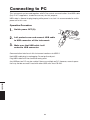
Connecting to PC …………………… 98
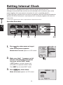
Setting Internal Clock ……………… 58
Remote Mode ………………………… 99
Measurement Preparation
Description
Calibration …………………………… 62
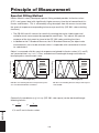
Principle of Measurement
Calibration Channel …………………… 62
Spectral Fitting Method …………… 102
User Calibration ……………………… 63
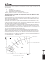
LvT∆uv ……………………………… 103
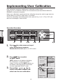
Implementing User Calibration …… 64
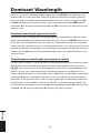
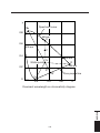
Dominant Wavelength …………… 104
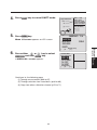
(1) Through measurement …………… 66
(2) Through selection from saved data … 68
(3) Copy from other calibration channel 70
Measurement of Object Color …… 106
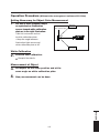
Operation Procedure ……………… 107
(Without data management software CS-S10w)
Operation Procedure ……………… 108
(With data management software CS-S10w)
Numerical value entry ranges …………… 71
Reset User Calibration ……………… 72
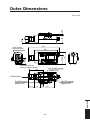
Outer Dimensions ………………… 109
Setting CH ID Name ………………… 74
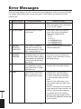
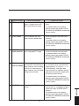
Error Messages …………………… 110
Entering Character ………………………… 77
Setting and Changing Target Color
(1) Through user calibration …………
(2) Through measurement ……………
(3) Through selection from saved data …
(4) By entering numerical value ………
……… 102
78
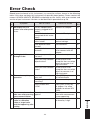
Error Check ………………………… 113
79
80
82
84
Identifying Version ………………… 116
Changing Luminance Unit (cd/m2 /fL)
118
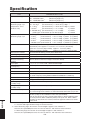
Specification ……………………… 120
Measurement
Measurement ………………………… 88
Measuring distance and measuring area … 88
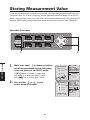
Storing Measurement Value ………… 90
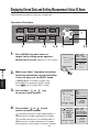
Displaying Stored Data and ………… 92
Setting Measurement Value ID Name
Deleting Stored Data ………………… 94
7
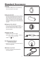
Standard Accessory
Lens Cap
• Attached to objective lens for protecting it
when not using this instrument.
Holding Cap CS-A24
• Prevents measuring angle selector position
from deviating during transfer. Remove one
when using this instrument and store not
to lose. Do not fail to set measuring angle
selector at center 0.2˚ for transfer before attaching this holding cap to measuring angle
selector.
ND Eyepiece Filter CS-A27
• Eases glare when peeping into finder to
measure high luminance object. Always set
this filter on finder when measuring high
luminance object.
AC Adapter AC-A23
• Supplies power from AC outlet.
Input: 100 V - 120 V
or 200 V - 240 V
1.0 A 50/60 Hz, 30-45 VA
Output: 5 V
2.8 A
,
Data Management Software
CS-S10w Standard
• Software to control this instrument from PC
for data management
USB Cable (2 m) IF-A17
• Used for communication between this
instrument and PC.
8
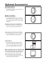
Optional Accessories
Close-Up lens No.107
Close-Up lens No.122
• Placed before objective lens for measurement of small object.
ND Filter (1/10) CS-A6
ND Filter (1/100) CS-A7
• Placed before objective lens for measurement of high luminance object, but sandwich step up ring (40.5 to 55 mm) CS-A26
inbetween.
Calibration Certificate (For ND Filter)
• Calibration certificate is available for ND
filters (1/10) CS-A6 and (1/100) CS-A7.
Step Up Ring (40.5 to 55 mm) CS-A26
• Placed before objective lens in using ND
filters (1/10) CS-A6 or (1/100) CS-A7.
Angle Finder VN
• Connected to finder for easing inconvenience felt in looking into finder in such
case as this instrument is set at low position. Use supplied adapter to connect.
White Calibration Plate (For 45/0) CS-A20
White Calibration Plate (For d/0) CS-A21
• Used for measurement of object colors.
White Calibration Plate Set CS-A22
• A set of white calibration plates (For 45-0)
CS-A20 and (For d-0) CS-A21.
9
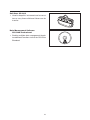
Soft Case CS-A23
• Used to keep this instrument and accessories or carry them with hand. Never use for
transfer.
Data Management Software
CS-S10w Professional
• Enables multiple data management thanks
to additional functions to that for CS-S10w
Standard.
10
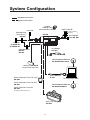
System Configuration
Standard accessories
Optional accessories
Lens Cap
Step Up Ring
(40.5-55mm)
CS-A26
AA-Size
Batteries (x4)
(commercially available)
Angle Finder VN
Adapter
( including
)
and Case.
CS-200
ND Filter
(1/10)CS-A6
(1/100)CS-A7
ND Eyepiece
Filter AC-A27
TARGET
COLOR
PEAK/VALLEY
SHUTTER
MEMORY
KEY LOCK
MEAS SPEED
CHAR MODE
ABS/DIFF
BACKLIGHT
RECALC
SHIFT
MENU
ESC
ENTER
AC Adapter
AC-A23
Close-Up Lenses
No.107
No.122
Data Management Software
CS-S10w Professional
Holding Cap CS-A24
(Used during shipment)
USB cable(2m)
IF-A17
White Calibration Plate (For 45/0)
CS-A20
White Calibration Plate (For d/0)
CS-A21
PC (commercially available)
Data Management Software
CS-S10w Standard
White Calibration Plate Set
CS-A22
(including CS-A20 and CS-A21.)
Soft Case
CS-A23
11
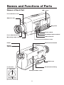
Names and Functions of Parts
Names of Each Part
LCD screen
Focus distance scale
Objective lens
Key panel
Power switch
AC adapter input terminal
Focus adjustment ring
USB connector
Measuring angle selector
Protect cover
Finder
Measurement button
Diopter
adjustment ring
Hand strap
Inside Finder
Screw hole for fixing
Aperture
battery chamber cover
in-finder indicator
12
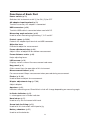
Functions of Each Part
Power switch:(p.23)
Switches this instrument on/off. (|) for ON; (O) for OFF
AC adapter input terminal:(p.23)
To which accessory AC adapter is connected.
USB connector: (p.98)
To which USB cable is connected when used with PC.
Measuring angle selector: (p.88)
Used to select measuring angle among 1˚, 0.2˚ and 0.1˚.
Protect cover: (p.23,98)
Protects AC adapter input terminal and USB connector.
Objective lens:
Directed to object for measurement.
Focus adjustment ring: (p.88)
Adjusts focus of objective lens before measurement.
Focus distance scale: (p.88)
Helps adjusting focus.
LCD screen: (p.18)
Displays various screens like measurement and menu.
Key panel: (p.14)
Offers several keys for operation of this instrument.
Measurement button: (p.88)
For measurement. Stops measurement when pressed during measurement.
Finder: (p.16, 88)
Used to observe object for measurement.
Diopter adjustment ring: (p.17,88)
Adjusts diopter.
Aperture: (p.16)
Indicates measuring area. Size of black circle will change depending on measuring angle.
In-finder indicator: (p.16)
Lv value appears on in-finder indicator.
Hand strap: (p.21)
Used to carry this instrument with hand.
Screw hole for fixing: (p.20)
Used to fix this instrument with tripod or jig.
Battery chamber: (p.25)
Used to set the batteries.
13
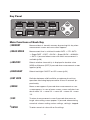
Key Panel
1
5
2
1
2
6
5
3
4
3
6
4
8
7
8
Main Functions of Each Key
①MEMORY
Measured data is stored in memory by pressing this key when
measurement screen and save screen appears.
②MEAS
SPEED
Measurement time is switched in order AUTO → LTD. AUTO
→ Super-FAST →FAST → SLOW → Super-SLOW → MANUAL
→ AUTO if pressed when screen with which measurement is
available.(p.28)
③ABS/DIFF
Selects whether chromaticity is displayed in absolute value
(ABS) or difference (DIFF) if pressed when measurement screen
appears.(p.36)
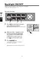
④BACKLIGHT
Selects backlight ON/OFF on LCD screen.(p.54)
⑤KEY
Switches between valid/invalid for acceptance of each key
operation after being kept pressed for at least 2 seconds approximately.
LOCK
⑥MENU
Menu screen appears if pressed when measurement or save
screen appears. In case of menu screen, screen switches in order of menu 1/4 → menu 2/4 → menu 3/4 →menu 4/4 →menu
1/4.
⑦ESC
To return to measurement screen if pressed when menu or
target value setting screen appears. If pressed when entering
numerical value or making various settings, setting is stopped.
⑧ENTER
To enter numerical value with or fix settings.
14
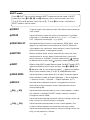
SHIFT mode
Press ➎ SHIFT key to switch between SHIFT mode and normal mode. In SHIFT
mode, keys from ➊ to ➍ , ➏ and ➑ become valid; in normal mode, keys from
① to ④, ⑥ and ⑧ become valid. Keys of ⑤, ⑦ and ➎ are always valid either in
SHIFT mode or normal mode.
➊TARGET
To go to target value setting screen from either measurement or
save screen.
➋ COLOR
If pressed when screen with which measurement is available,
color space is switched in order of Lvxy →Lvu'v' → LvT (d)uv →
XYZ →dominant wavelength →Lvxy.(p.35)
➌ PEAK/VALLEY
Switched to either of normal measurement, PEAK (Max. value
appears for continuous measurement) or VALLEY (Minimum
value appears for continuous measurement.) screen if pressed
when measurement screen appears.(p.44)
➍ SHUTTER
Selects whether finder shutter automatically closes for each
measurement or always opens if pressed when screen with
which measure is available. To close automatically, [ ] appears
on bottom left of screen and [ ] to always keep opened.(p.48)
➎ SHIFT
Selects either SHIF1 mode/ Normal mode. For SHIFT mode, [SFT]
appears on bottom left of screen and keys from ➊ to ➍, ➏, and
➑ become valid. In case of normal mode, [ ] appears on bottom
left of screen and keys from ① to ④, ⑥, and⑧ become valid.
➏ CHAR
MODE
➑ RECALC
key,
key
key,
key
If pressed when screen where ID is to input, character type to
enter switches in order of Capital Alphabet → Sm all Alphabet
→ Numerical Value → Symbol → Capital Alphabet. (p.77)
Pressed when calibration channel is changed for measurement value on measurement screen. Measurement value is
recalculated.(p.89)
If pressed when measurement or save screen appears, calibration channel is changed in SHIFT mode; memory channel is
changed in normal mode.
If pressed when entering numerical value or making various settings, numerical value or setting is changed.
If pressed when measurement or save screen appears, the
screen switches between measurement and save screen.
If pressed when entering numerical value or making various settings, cursor position is moved.
15
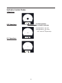
Indicator Inside Finder
1˚Aperture
Lv value appears
on in-finder indicator.
0.2˚ Aperture
K (displayed as
) and
M (displayed as ) show
x103 and x10 6 respectively.
0.1˚ Aperture
16
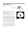
Diopter Adjustment
Rotate diopter adjustment ring for adjustment of
diopter.
Diopter adjustment ring
Adjust so that A or B on aperture or black circle
indicating measuring area looks clear when observing object through finder.
Adjustment would be easy starting with 1˚ aperture where object near aperture looks blur.
A
Make sure to adjust diopter before measurement.
Diopter should be adjusted for the eyesight of the
person who will be taking measurement. If diopter is not adjusted before focus measurement,
correct measurement value may not be expected. This is because the focus is actually off even
if you think it is correctly in focus. In addition, if
diopter is not correctly adjusted, you may see the
aperture moving depending on viewing angle.
∗You sometimes see small black dots or stripes
in internal finder. This happens due to characteristics of optical system, not dust or dirt in internal
finder. It gives no effect on measuring performance.
17
B
Installing
Setting status in this instrument is displayed.
<ANGL>
Currently selected measuring angle is
displayed.(1°,0.2°,0.1°)(p.88)
<SPD>
Currently selected measuring time is
displayed.(AUTO,LTD.AUTO, S-FAST,
FAST, SLOW, S-SLOW, MANU)(p.28)
<SYNC>
Synchronization frequency is displayed
when internal sync measurement mode
is set; NO SYNC is displayed when it is
not set.(p.30)
<LENS>
Currently selected lens type is displayed
.(STANDARD,No.107,No.122)(p.40)
<MEM>
Update method for directory to store
measurement value is displayed.(AUTO
NUM,MAN NUM,AUTOSAVE)(p.46)
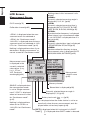
LCD Screen
Measurement Screen
CH ID name(p.74)
Calibration channel(p.62)
<PEAK> is displayed when the measurement result was obtained at
<PEAK> for “Continuous mode”;
<VALLEY> is displayed when the measurement result was obtained at <VALLEY> for “Continuous mode”.(p.44)
Nothing is displayed here when it was
obtained at “Single measurement” or
normal screen for “Continuous mode”.
Measurement result
is displayed in the
currently selected
color space. (Lvxy,
Lvu'v', LvT∆uv,
XYZ ,Dominant
wavelength)(p.34)
CH00 : <DEFAULT>
<PEAK>
Lv 7.09cd/m2
x 0.3369
y 0.3256
<MODE> SINGLE
[
]
■■■■■■■■■■■■ ■■ ■■ ■■ ■■ ■■ ■■■■ ■■■ ■■ ■■■■ ■■■■ ■■ ■■■■ ■■■■■ ■■ ■■■■ ■■■■■■ ■■ ■■ ■■■■■■■ ■■ ■■ ■■ ■■■■■■■■■■■■ [ 2° ]
<ANGL> 1° VIEW
<SPD> AUTO
<SYNC>NO SYNC
<LENS> STANDARD
<MEM> AUTO NUM
<MEMORY DATA>
M001 : SAMPLE1
Lv 38.09
x 0.4039
y 0.3815
Measurement
value ID name
(p.92)
■■■■■■■■■■■■ ■■ ■■ ■■ ■■ ■■ ■■■■ ■■■ ■■ ■■■■ ■■■ ■■ ■■■■ ■■ ■■ ■■■■ ■■ ■■ ■■ ■■ ■■ ■■ ■■■■■■■■■■■■ SINGLE is displayed when
the measurement mode
is set to “Single measurement”; CONT. is displayed
when set to normal screen
for “Continuous mode”.
(p.42)
Nothing is displayed here
when set to <PEAK> or
<VALLEY> for“Continuous
mode”.
Memory channel
Stored data is displayed.(p.90)
Currently selected observer angle is
displayed.(2°,10°)(p.32)
Battery level mark (
■■■■■■■■■■■■ ■■ ■■ ■■ ■■ ■■ ■■■■ ■■■ ■■ ■■■■ ■■■■ ■■ ■■■■ ■■■■■ ■■ ■■■■ ■■■■■■ ■■ ■■ ■■■■■■■ ■■ ■■ ■■ ■■■■■■■■■■■■ ,
■■■■■■■■■■■■ ■■ ■■ ■■ ■■ ■■ ■■■■ ■■■ ■■ ■■■■ ■■■■ ■■ ■■■■ ■■■■■ ■■ ■■■■ ■■■■■■ ■■ ■■ ■■■■■■■ ■■ ■■ ■■ ■■■■■■■■■■■■ ■■■■■■■■■■■■ ■■ ■■ ■■ ■■ ■■ ■■■■ ■■■ ■■ ■■■■ ■■■ ■■ ■■■■ ■■ ■■ ■■■■ ■■ ■■ ■■ ■■ ■■ ■■ ■■■■■■■■■■■■ )(p.24)
■■■■■■■■■■■■ ■■ ■■ ■■ ■■ ■■ ■■■■ ■■■ ■■ ■■■■ ■■■ ■■ ■■■■ ■■ ■■ ■■■■ ■■ ■■ ■■ ■■ ■■ ■■ ■■■■■■■■■■■■ is displayed when the finder shutter is set to automatically close for every measurement; is displayed when set to always open.(p.48)
[SFT] is displayed when this instrument is in SHIFT
] is displayed when SHIFT mode is released.
mode; [
18
Installing
19
Installing
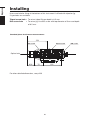
Installing
Use screw hole for fixing at the bottom of this instrument if utilized with tripod or jig.
2 type holes are available.
Tripod screw hole : To set on tripod. Screw depth is 6.5 mm.
ISO screw hole
: To set on jig. Use ISO screw with top diameter of 5mm and depth
of 6.5 mm.
Standard plane for distance measurements
154
ISO screw
Tripod screw
Optical axis
61.6
70
150
For other detailed dimensions, see p.109.
20
ISO screw
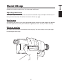
Hand strap can be used to carry this instrument with hand.
Adjusting hand strap
Insert your right hand between this instrument and hand strap, and adjust hand strap so
that your hand securely fits to the instrument without any gap.
How to carry
As shown in the figure, insert your right hand through hand strap and support the bottom
close to objective lens with your left hand. Tighten your arms to carry it more securely.
Notes on carrying
Be careful not to thud this instrument when carrying. You must always insert your right
hand through hand strap.
21
Installing
Hand Strap
Installing
Connecting AC Adapter
Either AC adapter(accessory) or 4 AA size batteries(commercially available) can be used
as power source of this instrument.
Warning
(Failure to adhere to the following points may result in death or serious injury.)
Always use the AC adapter and power cord supplied as a standard accessory
or optional (AC-A23), and connect it to indoor AC outlet of rated voltage and
frequency. Failure to follow either of these may result in damage to unit, fire or
electric shock.
If this instrument is not used for a long time, disconnect AC adapter from AC
outlet.
Accumulated dirt or water on prongs of AC adapter plug may cause fire and
should be removed.
Do not forcibly pull any part on power cord when unplugging since this may
cause fire or electric shock. Gently disconnect by holding plug. Also, do not
handle power cord with wet hands. Doing so may cause electric shock.
Do not forcibly bend, twist or pull power cord. Also, do not place heavy object
on power, or damage or modify one. Any of these may cause fire or electric
shock due to damage to power cord.
Do not disassemble or modify this instrument or AC adapter. Doing so may
cause fire or electric shock.
Should this instrument or AC adapter be damaged or smoke or odd smell be
generated, do not keep using one without correction. Doing so may cause fire.
In such situations, switch power off immediately, unplug AC adapter (or remove
batteries in using ones) and contact the nearest KONICA MINOLTA SENSING
authorized service facility.
Caution
(Failure to adhere to following points may result in injury or
damage to instrument or other property.)
Use this instrument near AC outlet for easy plugging or unplugging in using AC
adapter.
22
Installing
Connection Method
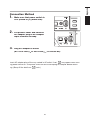
1.
2.
3.
Make sure that power switch is
OFF (slided to [O] mark side).
Lift protect cover and connect
AC adapter plug to AC adapter
input terminal on body.
Plug AC adapter to outlet
(AC 100V-120V
or 200-240V
, 50 Hz/60 Hz).
■■■■■■■■■■■■ ■■ ■■ ■■ ■■ ■■ ■■■■ ■■■ ■■ ■■■■ ■■■■ ■■ ■■■■ ■■■■■ ■■ ■■■■ ■■■■■■ ■■ ■■ ■■■■■■■ ■■ ■■ ■■ ■■■■■■■■■■■■ Insert AC adapter plug all the way seated in AC outlet. If not,
may appear when turning power switch on. Turn power switch off once and unplug AC adapter before resuming. (See p.24 for details on
mark.)
■■■■■■■■■■■■ ■■ ■■ ■■ ■■ ■■ ■■■■ ■■■ ■■ ■■■■ ■■■ ■■ ■■■■ ■■ ■■ ■■■■ ■■ ■■ ■■ ■■ ■■ ■■ ■■■■■■■■■■■■ ■■■■■■■■■■■■ ■■ ■■ ■■ ■■ ■■ ■■■■ ■■■ ■■ ■■■■ ■■■■ ■■ ■■■■ ■■■■■ ■■ ■■■■ ■■■■■■ ■■ ■■ ■■■■■■■ ■■ ■■ ■■ ■■■■■■■■■■■■ ■■■■■■■■■■■■ ■■ ■■ ■■ ■■ ■■ ■■■■ ■■■ ■■ ■■■■ ■■■ ■■ ■■■■ ■■ ■■ ■■■■ ■■ ■■ ■■ ■■ ■■ ■■ ■■■■■■■■■■■■ 23
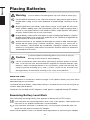
Installing
Placing Batteries
Warning
(Failure to adhere to the following points may result in death or serious injury.)
Do not dispose of batteries in fire, short their terminals, apply heat to them or disassemble them. Doing so may cause explosion or liquid leakage, resulting in fire or
injury.
Should liquid leak from battery and contact to eye, wash liquid off with clean
water without rubbing eyes and immediately seek for medical professional's
advice. In case liquid contacts with hand or clothes, wipe liquid off with plenty
of water. Avoid further use of such instrument.
Insulate battery contact with such object as tape in disposing of batteries. Contact
to other metal object may cause heat, explosion or fire. Follow local regulation for
proper disposal or recycle of batteries.
Should instrument or AC adapter be damaged or smoke or odd smell be generated, do not keep using it without correction. Doing so may cause fire. In
such situations, switch power off immediately, unplug AC adapter (or remove
batteries in using ones) and contact the nearest KONICA MINOLTA SENSING
authorized service facility.
Caution
(Failure to adhere to following points may result in injury or
damage to instrument or other property.)
Do not use batteries other than those specified by KONICA MINOLTA SENSING. Or do not use new and old batteries together or combine different type
batteries. When installing batteries in this instrument, make sure that they are
correctly placed according to (+) and (-) marks. Failure to any of these may
damage battery or leak liquid, resulting in fire, injury or air pollution.
Note on Use
Remove batteries if unused for 2 weeks or longer. If not, liquid in battery may leak, which
would damage this instrument.
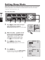
To avoid draining of battery, sleep mode setting is available for the case not using for 30
minutes. See p.56 for details.
If batteries are installed and AC adapter is used, power is supplied through AC adapter.
Remaining Battery Level Mark
Mark indicating remaining battery level appears on bottom left of LCD screen.
■■■■■■■■■■■■ ■■ ■■ ■■ ■■ ■■ ■■■■ ■■■ ■■ ■■■■ ■■■■ ■■ ■■■■ ■■■■■ ■■ ■■■■ ■■■■■■ ■■ ■■ ■■■■■■■ ■■ ■■ ■■ ■■■■■■■■■■■■ ■■■■■■■■■■■■ ■■ ■■ ■■ ■■ ■■ ■
■
■■ ■■ ■■■ ■■
■■■■■ ■■■■ ■
■
■■ ■■■
■ ■■ ■ ■■■ ■■ ■■■■ ■ ■■ ■■■■ ■■■■ ■ ■■ ■■■■ ■
■■ ■■■■■ ■■■■ ■ ■■ ■
■ ■■■ ■■ ■■ ■ ■ ■■
■■ ■■■
■■■■
■■
■ ■ ■■ ■■ ■■ ■■ ■■ ■■■■■■■■■■■■ ■■■■■■■■■■■■ ■■ ■■ ■■ ■■ ■■ ■■■■ ■■■ ■■ ■■■■ ■■■ ■■ ■■■■ ■■ ■■ ■■■■ ■■ ■■ ■■ ■■ ■■ ■■ ■■■■■■■■■■■■ mark indicates that remaining battery level is low. If this appears, replacement with
new ones or AC adapter connection is recommended.
mark indicates that there is no battery left. This instrument cannot be used. Replace with new ones or connect AC adapter.
Make sure that power switch is off before replacing batteries or connecting AC adapter.
24
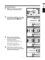
Installing
Placing Batteries
1.
2.
3.
Make sure that power switch is
OFF (slided to [O] mark side).
Open battery chamber cover while
pressing and sliding mark to the
direction shown in illustration.
Place 4 AA size batteries
following polarity indication
in battery chamber.
Do no touch or short terminals in
battery chamber. Doing so may cause
breakage of this instrument.
Use alkaline-manganese, lithium, or
nickel-metal-hydride batteries.
4.
Slide battery chamber cover to
the direction shown in illustration
and close until clicking.
25
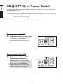
Installing
ON(|)/OFF(O) of Power Switch
To secure accurate measurement in either of following situations, 15-minute warm-up is
recommended at least.
1. Measuring low luminance light source object: At 2856K (Standard light source A) as measuring stick
10 cd/m2 or lower (1˚ Aperture)
250 cd/m2 or lower (0.2˚ Aperture)
1000 cd/m2 or lower (0.1˚ Aperture)
2. Outside room temperature and normal humidity ranges
Turning power switch ON
1.
Slide power switch to ON (|) side.
Measurement screen appears 5
seconds after initial screen on LCD.
Turning power switch OFF
2.
Slide power switch to OFF (O
side) after measurement.
After measurement, do not switch
OFF until measurement value appears.
When message “PLEASE WAIT...”
appears, do not switch OFF, either.
Doing so may break stored data.
26
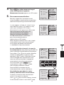
Setting
27
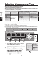
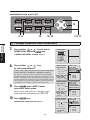
Selecting Measurement Time
Select measurement time depending on purpose.
7 modes are available for measurement time.
Select the mode with long measurement time when repeated accuracy is required such
as when measuring object of low luminance.
Setting
∗ Setting at the shipment from factory : AUTO.
Measurement Time calculated by formula Time for integration
(Time for integration x 2 +Time to open/close Time for sensor to measure light
Zero Calibration
shutter + Time for calculation) indicating time
indicating “exposure time”.
needed for actual measurement.
MEAS
SPEED
Super-FAST Not be done every time ∗1
FAST
SLOW
Super-SLOW Done every time
LTD.AUTO ※2 automatically
AUTO
※3
MANUAL
0.5s approx.
1s approx.
3s approx.
12s approx.
1s or 3s approx.
1s to 60 s
1s to 60 s (Every 1s)
300 ms
300 ms
1300 ms
1300 ms x 4 times
300 ms or 1300 ms
∗ Zero calibration is performed automatically one minute after previous measurement.
∗ 2 Selects FAST/SLOW automatically depending on luminance. Luminance for which FAST/SLOW is switchable is as follows for measuring angle 1˚.
FAST → SLOW: Lv =20 cd/m2 or lower (Measurement is redone in SLOW mode.)
SLOW → FAST: Lv =40 cd/m2 pt or higher
∗ 3 Selects the measurement time automatically depending on luminance.
For measuring angle 1°, when luminance is higher than 20 cd/m2, the measurement time switches as LTD.
AUTO mode. When luminance is 20 cd/m2 or lower, the measurement time is calculated depend on luminance
as following examples. The higher limit is 60 s.
LV
Measurement Time
20.0 cd/m2
3 s approx.
15.0 cd/m2
7 s approx.
10.0 cd/m2
14 s approx.
6.6 cd/m2
30 s approx.
4.6 cd/m2
60 s approx.
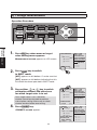
Operation Procedure
5
1.
2
3
1
4, 6
7
Press ESC key when menu or target
value setting menu appears.
<ANGL> 1° VIEW
<SPD> AUTO
>NO SYNC
Lv ------cd/m2 <<SYNC
LENS>STANDARD
<MEM> AUTO NUM
x -----<MEMORY DATA>
y ------
CH00: < DEFAULT>
Measurement screen appears on LCD screen.
2.
Make sure that [ ] appears on bottom
left of measurement screen indicating
it has not been set for SHIFT mode.
If [SFT] appears instead, it means that
instrument is to operate in SHIFT mode.
Press SHIFT key to cancel SHIFT mode.
28
<MODE>SINGLE
[
]
[ 2° ]
MOOO:(NO DATA)
Lv -----x -----y ------
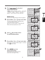
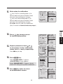
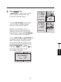
3.
Press MEAS SPEED key to select
measurement speed.
<ANGL> 1° VIEW
<SPD> MANU: 1
>NO SYNC
Lv ------cd/m2 <<SYNC
LENS>STANDARD
<MEM> AUTO NUM
x -----<MEMORY DATA>
y ------
CH00: < DEFAULT>
<SPD> switches in order of AUTO → LTD.AUTO
<MODE>SINGLE
[
MANU Setting
<ANGL> 1° VIEW
<SPD> MANU: 1
>NO SYNC
Lv ------cd/m2 <<SYNC
LENS>STANDARD
MEAS SPEED
<MEM> AUTO NUM
x -----<MEMORY DATA>
y ------
or
<
key to set value.
key for larger number. If kept pressed,
value continuously increases.
key for smaller number. If kept pressed,
value continuously becomes small.
1s
>
OK
: [ENTER] DATA)
MOOO:(NO
-----CANCEL : Lv
[ESC]
x -----<MODE>SINGLE
y -----[
]
[ 2° ]
<ANGL> 1° VIEW
<SPD> MANU: 1
>NO SYNC
Lv ------cd/m2 <<SYNC
LENS>STANDARD
MEAS SPEED
<MEM> AUTO NUM
x -----<MEMORY DATA>
y ------
CH00: < DEFAULT>
<
31s
>
OK
: [ENTER] DATA)
MOOO:(NO
-----CANCEL : Lv
[ESC]
x -----<MODE>SINGLE
y -----[
]
[ 2° ]
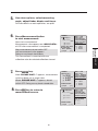
5.
<ANGL> 1° VIEW
<SPD> MANU: 1
>NO SYNC
Lv ------cd/m2 <<SYNC
LENS>STANDARD
MEAS SPEED
<MEM> AUTO NUM
x -----<MEMORY DATA>
y ------
press
key to move cursor
to second digit position.
CH00: < DEFAULT>
<
31s
>
OK
: [ENTER] DATA)
MOOO:(NO
-----CANCEL : Lv
[ESC]
x -----<MODE>SINGLE
y -----[
]
[ 2° ]
6.
Press either
or
key to set value.
<ANGL> 1° VIEW
<SPD> MANU: 1
>NO SYNC
Lv ------cd/m2 <<SYNC
LENS>STANDARD
MEAS SPEED
<
MEM
>
AUTO NUM
x -----<
MEMORY DATA>
y ------
CH00: < DEFAULT>
<
Selectable measurement time range is 1 to 60 sec.
Press ESC key to stop.
30s
>
OK
: [ENTER] DATA)
MOOO:(NO
-----CANCEL : Lv
[ESC]
x -----<MODE>SINGLE
y -----[
]
[ 2° ]
7.
<ANGL> 1° VIEW
<SPD> MANU :30
>NO SYNC
Lv ------cd/m2 <<SYNC
LENS>STANDARD
<MEM> AUTO NUM
x -----<MEMORY DATA>
y ------
Press ENTER key to fix
measurement time.
CH00: < DEFAULT>
Measurement time setting remains
even after switching OFF (O).
<MODE>SINGLE
[
29
]
[ 2° ]
MOOO:(NO DATA)
Lv -----x -----y ------
MEAS
SPEED
4.
[ 2° ]
CH00: < DEFAULT>
Screen to set measurement time from appears.
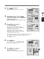
Press either
]
MOOO:(NO DATA)
Lv -----x -----y ------
Setting
→ S-FAST → FAST → SLOW → S-SLOW →
MANU → AUTO while this key is pressed.
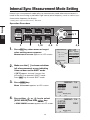
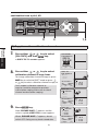
Internal Sync Measurement Mode Setting
Internal sync measurement mode refers to measurement mode where measurement is
made in the same timing as periodical light source pulse frequency, such as vertical synchronization frequency for display.
∗ Setting at the shipment from factory : NO SYNC
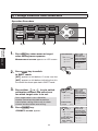
Operation Procedure
Setting
SYNC
MODE
5, 7
2
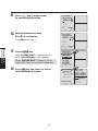
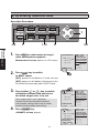
1.
3
1, 10
4, 9
Press ESC key when menu or target
value setting menu appears.
5
4, 6
<ANGL> 1° VIEW
<SPD> AUTO
> 60.00Hz
Lv ------cd/m2 <<SYNC
LENS>STANDARD
<MEM> AUTO NUM
x -----<MEMORY DATA>
y ------
CH00: < DEFAULT>
Measurement screen appears on LCD screen.
<MODE>SINGLE
[
2.
]
[ 2° ]
MOOO:(NO DATA)
Lv -----x -----y ------
Make sure that [ ] is shown on bottom
left of measurement screen indicating
it has not been set for SHIFT mode.
If [SFT] appears instead, it means that
instrument is to operate in SHIFT mode.
Press SHIFT key to cancel SHIFT mode.
3.
<MENU> 1/4
CH SETTING
MEAS MODE
SINGLE
SYNC MODE
DELETE
Press MENU key.
Menu 1/4 screen appears on LCD screen.
[
4.
BREAK : [ESC]
[ 2° ]
<MENU> 1/4
CH SETTING
MEAS MODE
SINGLE
SYNC MODE
DELETE
Press either
or
key to select
[SYNC MODE] and then ENTER key.
< SYNC MODE> screen appears on LCD screen.
[
30
]
]
BREAK : [ESC]
[ 2° ]
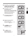
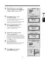
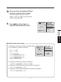
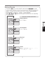
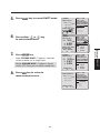
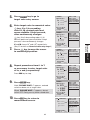
5.
Press either
or
key
to set arbitrary value.
NO SYNC
[
OK: [ENTER] CANCEL: [ESC]
]
[ 2° ]
NO SYNC
[
OK: [ENTER] CANCEL: [ESC]
]
[ 2° ]
<SYNC MODE>
Press
key to move cursor
to second digit position.
NO SYNC
[
8.
OK: [ENTER] CANCEL: [ESC]
]
[ 2°]
NO SYNC
[
200.00Hz
(SYNC)
OK: [ENTER] CANCEL: [ESC]
]
[ 2° ]
<MENU> 1/4
CH SETTING
MEAS MODE
SINGLE
SYNC MODE
DELETE
Press ENTER key to show
<MENU>1/4 screen.
Now frequency has been set.
[
10.
260.00Hz
(SYNC)
<SYNC MODE>
Repeat the same procedures
6. and 7. as necessary.
Selectable frequency range is from 40.00Hz
to 200.00Hz. Press ESC to stop.
9.
260.00Hz
(SYNC)
]
BREAK : [ESC]
[ 2° ]
<ANGL> 1° VIEW
<SPD> AUTO
> 200.00Hz
Lv ------cd/m2 <<SYNC
LENS> STANDARD
<MEM> AUTO NUM
x -----<MEMORY DATA>
y ------
Press ESC to return to
measurement screen.
CH00: < DEFAULT>
Internal sync mode setting remains
even after switching OFF (O).
<MODE>SINGLE
[
31
]
[ 2° ]
MOOO:(NO DATA)
Lv -----x -----y ------
SYNC
MODE
<SYNC MODE>
key: 0 to 9 (0 to 2 in 100 position) in descending
order, decimal point and space available.If kept
pressed, numerical value continuously increases.
key: 9 to 0 (2 to 0 in 100 position) in
ascending order, decimal point and space
available. If kept pressed, numerical
value continuously becomes small.
7.
60.00Hz
(SYNC)
Setting
6.
<SYNC MODE>
Press either
or
key to move
inversion cursor from [NO SYNC]
to [SYNC] so that light source
pulse frequency can be entered.
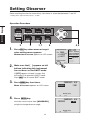
Setting Observer
Color matching function for chromaticity calculation is selectable between 2˚ and 10˚.
∗ Setting at the shipment from factory : 2˚ OBS
Operation Procedure
Setting
OBSERVER
2
1.
3
1, 7
6
Press ESC key when menu or target
value setting menu appears.
Measurement screen appears on LCD screen.
4, 5
CH00: < DEFAULT>
Lv 20.80cd/m2
x 0.4476
y 0.4477
<MODE>SINGLE
[
2.
]
[ 2° ]
<ANGL> 1° VIEW
<SPD> AUTO
<SYNC> 200.00Hz
<LENS>STANDARD
<MEM> AUTO NUM
<MEMORY DATA>
MOOO:(NO DATA)
Lv -----x -----y ------
Make sure that [ ] appears on left
bottom indicating this instrument
has not been set for SHIFT mode.
If [SFT] appears instead, it means that
instrument is to operate in SHIFT mode.
Press SHIFT key to cancel SHIFT mode.
3.
<MENU>
Press MENU key four times.
OBSERVER
Menu 4/4 screen appears on LCD screen.
[
4.
]
BREAK : [ESC]
[ 2° ]
<MENU>
Press ENTER key.
OBSERVER
Inversion cursor moves from [OBSERVER]
to right to change observer angle.
[
32
]
4/4
2˚ OBS
BREAK : [ESC]
[ 2° ]
4/4
2˚ OBS
5.
<MENU>
Press either
or
key to set
either for [2˚OBS] or [10˚OBS].
Press ESC key to stop.
BREAK : [ESC]
[ 2° ]
<MENU>
Press ENTER key.
After“ PLEASE WAIT...” appears,
inversion cursor moves from [OBSERVER]
to right to change observer angle.
When“ PLEASE WAIT...” appears, do not
switch OFF. Doing so may break stored data.
Press ESC key to return to
measurement screen.
OBSERVER
[
]
BREAK : [ESC]
[ 10° ]
CH00: < DEFAULT>
33
<ANGL> 1° VIEW
<SPD> AUTO
<SYNC> 200.00Hz
<LENS>STANDARD
<MEM> AUTO NUM
<MEMORY DATA>
Y ------cd/m2
x -----y -----MOOO:(NO DATA)
Setting remains even after switching OFF (O).
When observer angle is set to 10˚, Lv display
changes to Y display. Lv and Y display in stored
data is retained after changing observer angle.
4/4
10˚ OBS
<MODE>SINGLE
[
]
[ 10° ]
Lv -----x -----y ------
OBSERVER
7.
]
Setting
[
6.
4/4
10˚ OBS
OBSERVER
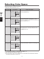
Selecting Color Space
See below table for available color space.
∗ Setting at the shipment from factory : Lvxy
Color space
LCD Screen
Lvxy ∗1
CH00: < DEFAULT >
<ANGL> 1° VIEW
<SPD> AUTO
<SYNC>200.00Hz
<LENS >STANDARD
<MEM >AUTO NUM
<MEMORY DATA>
Setting
Lv ------cd/m2
x -----y -----MOOO:(NO DATA)
<MODE >SINGLE
[
COLOR
Lvu’v’ ∗1
]
[ 2° ]
CH00: < DEFAULT >
[
Lv T ∆uv ∗2
]
[ 2° ]
CH00: < DEFAULT >
<ANGL> 1° VIEW
<SPD> AUTO
<SYNC>200.00Hz
<LENS >STANDARD
<MEM >AUTO NUM
<MEMORY DATA>
[
]
[ 2° ]
<ANGL> 1° VIEW
<SPD> AUTO
<SYNC>200.00Hz
<LENS >STANDARD
<MEM >AUTO NUM
<MEMORY DATA>
Displayed and output in luminance Lv, correlated
color temperature T and color difference from
blackbody locus ∆uv.
Lv -----T -----Δuv ------
Displayed and output in tristimulus values X, Y, Z.
XYZ
CH00: < DEFAULT >
X -----Y -----Z -----<MODE >SINGLE
[
Dominant
wavelength∗3
Displayed and output in luminance Lv and u’v’
chromaticity diagram (CIE 1976 UCS chromaticity
diagram) coordinates u’, v’
Lv -----x’ -----y’ ------
Lv ------cd/m2
T ------K
∆uv -----MOOO:(NO DATA)
<MODE >SINGLE
Displayed and output in luminance Lv and chromaticity coordinates x,y.
Lv -----x -----y ------
Lv ------cd/m2
u’ -----v’ -----MOOO:(NO DATA)
<MODE >SINGLE
Display Description
]
[ 2° ]
<ANGL> 1° VIEW
<SPD> AUTO
<SYNC>200.00Hz
<LENS >STANDARD
<MEM >AUTO NUM
<MEMORY DATA>
MOOO:(NO DATA)
X -----Y -----Z ------
Displayed and output in dominant wavelength λd.
CH00: < DEFAULT >
λd -----nm
<ANGL> 1° VIEW
<SPD> AUTO
<SYNC>200.00Hz
<LENS >STANDARD
<MEM >AUTO NUM
<MEMORY DATA>
MOOO:(NO DATA)
∆d ------
<MODE >SINGLE
[
]
[ 2° ]
∗1 Y is displayed instead of Lv when observer angle is 10˚.
∗2 Not displayed when observer angle is 10˚.
∗3 For non-spectral colors, the complementary wavelength will be displayed. However,
the display indication will remain λd.
34
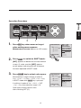
Operation Procedure
Setting
COLOR
2
1.
3
1
Press ESC key when menu or target
value setting menu appears.
<ANGL> 1° VIEW
<SPD> AUTO
>200.00Hz
Lv ------cd/m2 <<SYNC
LENS>STANDARD
<MEM> AUTO NUM
x -----<MEMORY DATA>
y ------
CH00: < DEFAULT>
Measurement screen appears on LCD screen.
<MODE>SINGLE
[
2.
]
[ 2° ]
MOOO:(NO DATA)
Lv -----x -----y ------
Press SHIFT to switch to SHIFT mode.
[SFT] appears on bottom left of measurement
screen. Or make sure that [SFT] appears
on left bottom indicating that this instrument
has been operated in SHIFT mode.
3.
Press COLOR key to select color space.
<ANGL> 1° VIEW
<SPD> AUTO
>200.00Hz
Lv ------cd/m2 <<SYNC
LENS>STANDARD
<
MEM
>
AUTO NUM
u’ -----<
MEMORY DATA>
v’ ------
CH00: < DEFAULT>
Measurement screen switches in order of
Lvxy → Lvu’v’ → LvTΔuv → XYZ → λd → Lvxy
in SHIFT mode while COLOR key is pressed.
It switches in order of Yxy → Yu'v' → XYZ
→ λd → Yxy when observer angle is 10˚.
Color space setting remains even
after switching OFF (O).
35
<MODE>SINGLE
[
]
[ 2° ]
MOOO:(NO DATA)
Lv -----u’ -----v’ ------
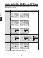
Selecting Absolute Value (ABS)/Difference (DIFF) Display
Whether chromaticity value is shown in absolute (ABS) or difference (DIFF) is selectable.
See below table for each case.
∗ Setting at the shipment from factory : Absolute value (ABS)
Color Space
LVxy ∗1
Switching between Absolute Value (ABS) and Difference (DIFF) Dominant wavelength
LV・x・y
%LV・∆LV・∆x・∆y
Setting
CH00: < DEFAULT >
<ANGL> 1° VIEW
<SPD> AUTO
Lv ------cd/m2 <SYNC>200.00Hz
<LENS >STANDARD
x -----<MEM >AUTO NUM
<MEMORY DATA>
y -----MOOO:(NO DATA)
ABS/DIFF
<MODE >SINGLE
[
LVu’v’ ∗1
]
[ 2° ]
Lv -----x -----y ------
LV・u’・v’
CH00: < DEFAULT >
[
LV T ∆uv ∗2
]
[ 2° ]
Lv -----x’ -----y’ ------
LV ・T ・∆uv
CH00: < DEFAULT >
[
XYZ
]
[ 2° ]
X -----Y -----Z -----<MODE >SINGLE
]
[ 2° ]
<ANGL> 1° VIEW
<SPD> AUTO
<SYNC>200.00Hz
<LENS >STANDARD
<MEM >AUTO NUM
<MEMORY DATA>
MOOO:(NO DATA)
X -----Y -----Z ------
]
[ 2° ]
CH00: < DEFAULT >
%Lv ------ %
∆Lv ------cd/m2
∆u’ -----∆v’ ------
<MODE >SINGLE
[
]
[ 2° ]
<ANGL> 1° VIEW
<SPD> AUTO
<SYNC>200.00Hz
<LENS >STANDARD
<MEM >AUTO NUM
<MEMORY DATA>
MOOO:(NO DATA)
%Lv -----∆Lv -----∆u’ -----∆v’ ------
CH00: < DEFAULT >
<ANGL> 1° VIEW
<SPD> AUTO
%Lv ------ % <SYNC>200.00Hz
<LENS >STANDARD
∆Lv ------cd/m <MEM >AUTO NUM
MEMORY DATA >
∆T ------K <MOOO:(NO
DATA)
2
<MODE >SINGLE
[
]
[ 2° ]
%Lv -----∆Lv -----∆T ------
CH00: < DEFAULT >
∆X -----∆Y -----∆Z -----<MODE >SINGLE
[
]
[ 2° ]
%X・%Y・%Z
<ANGL> 1° VIEW
<SPD> AUTO
<SYNC>200.00Hz
<LENS >STANDARD
<MEM >AUTO NUM
<MEMORY DATA>
MOOO:(NO DATA)
∆X -----∆Y -----∆Z ------
CH00: < DEFAULT >
%X ------ %
%Y ------ %
%Z ------ %
<MODE >SINGLE
[
]
[ 2° ]
<ANGL> 1° VIEW
<SPD> AUTO
<SYNC>200.00Hz
<LENS >STANDARD
<MEM >AUTO NUM
<MEMORY DATA>
MOOO:(NO DATA)
%X -----%Y -----%Z ------
∆λd ∗3
λd
CH00: < DEFAULT >
λd ------nm
<MODE >SINGLE
[
[
MOOO:(NO DATA)
%Lv -----∆Lv -----∆x -----∆y ------
∆X・∆Y・∆Z
CH00: < DEFAULT >
Dominant
wavelength
Lv -----T -----Δuv ------
X・Y・Z
[
<MODE >SINGLE
<ANGL> 1° VIEW
<SPD> AUTO
<SYNC>200.00Hz
<LENS >STANDARD
<MEM >AUTO NUM
<MEMORY DATA>
%LV ・∆LV・∆T
<ANGL> 1° VIEW
<SPD> AUTO
<SYNC>200.00Hz
<LENS >STANDARD
<MEM >AUTO NUM
<MEMORY DATA>
Lv ------cd/m2
T ------K
∆uv -----MOOO:(NO DATA)
<MODE >SINGLE
------ %
------cd/m2
-----------
%LV・∆LV・∆u’・∆v’
<ANGL> 1° VIEW
<SPD> AUTO
<SYNC>200.00Hz
<LENS >STANDARD
<MEM >AUTO NUM
<MEMORY DATA>
Lv ------cd/m2
u’ -----v’ -----MOOO:(NO DATA)
<MODE >SINGLE
CH00: < DEFAULT >
%Lv
∆Lv
∆x
∆y
]
[ 2° ]
<ANGL> 1° VIEW
<SPD> AUTO
<SYNC>200.00Hz
<LENS >STANDARD
<MEM >AUTO NUM
<MEMORY DATA>
MOOO:(NO DATA)
∆d ------
CH00: < DEFAULT >
∆λd ------nm
<MODE >SINGLE
[
]
<ANGL> 1° VIEW
<SPD> AUTO
<SYNC>200.00Hz
<LENS >STANDARD
<MEM >AUTO NUM
<MEMORY DATA>
MOOO:(NO DATA)
∆λd ------
[ 2° ]
∗1 Y is displayed instead of Lv when observer abgle is 10˚.
∗2 Not displayed when observer angle is 10˚.
∗3 Even if either the measured value, target color, or both are the complementary wavelength, the difference between the two values will be displayed. Further, even in such
case, the display indication will remain ∆λd.
36
Operation Procedure
3
Setting
ABS/DIFF
2
1.
1
Press ESC key when menu or target
value setting menu appears.
<ANGL> 1° VIEW
<SPD> AUTO
>200.00Hz
Lv ------cd/m2 <<SYNC
LENS>STANDARD
<MEM> AUTO NUM
x -----<MEMORY DATA>
y ------
CH00: < DEFAULT>
Measurement screen appears on LCD screen.
<MODE>SINGLE
[
2.
]
[ 2° ]
MOOO:(NO DATA)
Lv -----x -----y ------
Make sure that [ ] appears on left
bottom indicating this instrument
has not been set for SHIFT mode.
If [SFT] appears instead, it means that
instrument is to operate in SHIFT mode.
Press SHIFT key to cancel SHIFT mode.
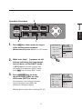
3.
Press ABS/DIFF key to show
absolute value (ABS) or color
difference (DIFF) to select.
<ANGL> 1° VIEW
<SPD> AUTO
>200.00Hz
%Lv ------ % <<SYNC
LENS>STANDARD
ΔLv ------cd/m2 <MEM> AUTO NUM
<MEMORY DATA>
Δx -----CH00: < DEFAULT>
Measurement value switches between
that for absolute value (ABS) and
difference while pressing key.
Setting remains even after switching OFF (O).
37
Δy ------
<MODE>SINGLE
[
]
[ 2° ]
MOOO:(NO DATA)
%Lv -----ΔLv -----Δx -----Δy ------
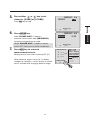
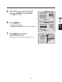
Selecting Digit for Chromaticity Display
This is selectable either 4 or 3.
If measurement value on LCD screen is illegible because of blinking, set for 3
digits.
∗ Setting at the shipment from factory : 4 FIGURES
Operation Procedure
Setting
DISPLAY
DIGYTS
2
1.
3
1, 7
6
Press ESC key when menu or target
value setting menu appears.
Measurement screen appears on LCD screen.
5
4, 5
CH00: < DEFAULT>
Lv 20.80cd/m2
x 0.4476
y 0.4477
<MODE>SINGLE
[
2.
]
[ 2° ]
<ANGL> 1° VIEW
<SPD> AUTO
<SYNC> 200.00Hz
<LENS>STANDARD
<MEM> AUTO NUM
<MEMORY DATA>
MOOO:(NO DATA)
Lv -----x -----y ------
Make sure that [ ] appears on left
bottom indicating this instrument
has not been set for SHIFT mode.
If [SFT] appears instead, it means that
instrument is to operate in SHIFT mode.
Press SHIFT key to cancel SHIFT mode.
3.
<MENU> 2/4
OBJECTIVE LENS STANDARD
DISPLAY DIGITS
4 FIGURES
MEMORY MODE
AUTO NUM
DATA PROTECT
ON
Press MENU key twice.
Menu 2/4 screen appears on LCD screen.
[
4.
BREAK : [ESC]
[ 2° ]
<MENU> 2/4
OBJECTIVE LENS STANDARD
DISPLAY DIGITS
4 FIGURES
MEMORY MODE
AUTO NUM
DATA PROTECT
ON
Press either
or
key to select
[DISPLAY DIGITS] and then ENTER key.
Inversion cursor moves from [DISPLAY DIGITS]
to right to change digits to display.
[
38
]
]
BREAK : [ESC]
[ 2° ]
5.
Press ESC key to stop.
[
<MENU>
Press ENTER key.
OBJECTIVE LENS
DISPLAY DIGITS
MEMORY MODE
DATA PROTECT
Inversion cursor returns
to [DISPLAY DIGITS]. Now change has been set.
[
7.
BREAK : [ESC]
[ 2° ]
Press ESC key to return to
measurement screen.
]
BREAK : [ESC]
[ 2° ]
CH00: < DEFAULT>
Setting remains even after switching OFF (O).
Lv 20.80cd/m2
x 0.448
y 0.448
<MODE>SINGLE
[
39
]
2/4
STANDARD
3 FIGURES
AUTO NUM
ON
[ 2° ]
<ANGL> 1° VIEW
<SPD> AUTO
<SYNC> 200.00Hz
<LENS>STANDARD
<MEM> AUTO NUM
<MEMORY DATA>
MOOO:(NO DATA)
Lv -----x -----y ------
DISPLAY
DIGYTS
6.
]
Setting
<MENU> 2/4
OBJECTIVE LENS STANDARD
3 FIGURES
DISPLAY DIGITS
MEMORY MODE
AUTO NUM
DATA PROTECT
ON
Press either
or
key to set for
either [4 FIGURES] or [3 FIGURES].
Selecting Lens Type
Setting
Use optional accessory close-up lens for small area measurement. See
instruction manual for close-up lens for the placement of one. If close-up lens is
to use, measurement value is required for calibration of lens transmission factor.
Since calibration value varies depending on lens type, lens type has to be set in
this instrument in advance. Erroneous setting causes incorrect measurement.
Below table shows lens to set and setting for this instrument.
OBJECTIVE
LENS
∗
Lens to Set
No lens
Setting
STANDARD
Close-Up lens Close-Up lens
No.107
No.122
No.107
No.122
Arbitrary lens like optional accessory ND
filter (1/10) CS-A6, ND Filter (1/100) CS-A7,
Combination of close-up lens and ND filter
USER1∗
USER2∗
USER3∗
Setting at the shipment from factory : STANDARD
∗ Use standard accessory data management software CS-S10w Standard or optional
CS-S10w Professional to avail more lens type like USER1, USER2 and USER3, and
register calibration value for lens other than close-up lens No.107 and No.122 set in
USER1, USER2 or USER3. See instruction manual for data management software for
details.
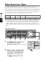
Operation Procedure
2
1.
3
1, 7
6
Press ESC key when menu or target
value setting menu appears.
Measurement screen appears on LCD screen.
4, 5
CH00: < DEFAULT>
Lv 20.80cd/m2
x 0.4476
y 0.4477
<MODE>SINGLE
[
2.
Make sure that [ ] appears on left
bottom indicating this instrument
has not been set for SHIFT mode.
If [SFT] appears instead, it means that
instrument is to operate in SHIFT mode.
Press SHIFT key to cancel SHIFT mode.
40
]
[ 2° ]
<ANGL> 1° VIEW
<SPD> AUTO
<SYNC> 200.00Hz
<LENS>STANDARD
<MEM> AUTO NUM
<MEMORY DATA>
MOOO:(NO DATA)
Lv -----x -----y ------
3.
Menu 2/4 screen appears on LCD screen.
[
<MENU>
Press either
or
key to select
[OBJECTIVE LENS] and then ENTER key.
OBJECTIVE LENS
DISPLAY DIGITS
MEMORY MODE
DATA PROTECT
Inversion cursor moves from
[OBJECTIVE LENS] to right to change lens type.
[
5.
Press either
or
to switch lens type.
BREAK : [ESC]
[ 2° ]
]
2/4
STANDARD
4 FIGURES
AUTO NUM
ON
BREAK : [ESC]
[ 2° ]
<MENU>
key
If
is pressed, lens type switches in order of
[STANDARD] → [No.122] → [No.107] → [STANDARD]
. Keep pressing to continuously switch.
If
is pressed, lens type switches in order of
[STANDARD] → [No.107] → [No.122] → [STANDARD]
. Keep pressing to continuously switch.
OBJECTIVE LENS
DISPLAY DIGITS
MEMORY MODE
DATA PROTECT
[
]
2/4
No.107
4 FIGURES
AUTO NUM
ON
BREAK : [ESC]
[ 2° ]
Set to [No.107] for close-up lens No.107, [No.122] for close-up lens
No.122 and [STANDARD] for nothing with objective lens.
Press ESC key to stop.
6.
<MENU> 2/4
OBJECTIVE LENS
No.107
DISPLAY DIGITS
4 FIGURES
MEMORY MODE
AUTO NUM
DATA PROTECT
ON
Press ENTER key.
Inversion cursor returns to [OBJECTIVE LENS].
Now change has been set.
[
7.
Press ESC key to return to
measurement screen.
]
BREAK : [ESC]
[ 2° ]
CH00: < DEFAULT>
Setting remains even after switching OFF (O).
Lv 20.80cd/m2
x 0.448
y 0.448
<MODE>SINGLE
[
41
]
[ 2° ]
<ANGL> 1° VIEW
<SPD> AUTO
<SYNC> 200.00Hz
<LENS>No.107
<MEM> AUTO NUM
<MEMORY DATA>
MOOO:(NO DATA)
Lv -----x -----y ------
OBJECTIVE
LENS
4.
]
Setting
<MENU> 2/4
OBJECTIVE LENS STANDARD
DISPLAY DIGITS
4 FIGURES
MEMORY MODE
AUTO NUM
DATA PROTECT
ON
Press MENU key twice.
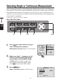
Selecting Single or Continuous Measurement
Here, measurement mode is selectable between “Single measurement” and “Continuous
measurement”. Former means one measurement for one press and the latter continuous
measurement from one press to another press of any key. In case of “Continuous measurement”, you can also view max and min values during continuous measurement when
measurement is completed.
∗ Setting at the shipment from factory : SINGLE
Setting
Operation Procedure
MEAS
MODE
2
1.
3
1, 7
6
Press ESC key when menu or target
value setting menu appears.
Measurement screen appears on LCD screen.
4, 5
CH00: < DEFAULT>
Lv 0.45cd/m2
x 0.3855
y 0.4447
<MODE>SINGLE
[
2.
]
[ 2° ]
<ANGL> 1° VIEW
<SPD> AUTO
<SYNC>NO SYNC
<LENS>STANDARD
<MEM> AUTO NUM
<MEMORY DATA>
M003:
Lv
x
y
0.54
0.4004
0.4123
Make sure that [ ] appears on left
bottom indicating this instrument
has not been set for SHIFT mode.
If [SFT] appears instead, it means that
instrument is to operate in SHIFT mode.
Press SHIFT key to cancel SHIFT mode.
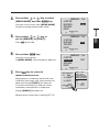
3.
<MENU> 1/4
CH SETTING
MEAS MODE
SINGLE
SYNC MODE
DELETE
Press MENU key.
Menu 1/4 screen appears on LCD screen.
[
42
]
BREAK : [ESC]
[ 2° ]
4.
Inversion cursor moves from [MEAS MODE]
to right to change measurement mode.
[
<MENU>
Press either
or
key to
set for [SINGLE] or [CONT.].
CH SETTING
MEAS MODE
SYNC MODE
DELETE
Press ESC key to stop.
[
6.
]
BREAK : [ESC]
[ 2° ]
CH SETTING
MEAS MODE
SYNC MODE
DELETE
[
Press ESC key to return to
measurement screen.
]
Setting remains even after switching OFF (O).
43
Lv 0.45cd/m2
x 0.3855
y 0.4447
<MODE> CONT.
[
]
1/4
CONT.
BREAK : [ESC]
[ 2° ]
CH00: < DEFAULT>
Measurement is made only once when user
calibration and target color measurement are
done even though [CONT.] has been set.
In case of measuring max and min values,
continuous measurement is made even
though [SINGLE] has been set.
1/4
CONT.
<MENU>
Press either ENTER key.
Inversion cursor returns
to [MEAS MODE]. Now change has been set.
7.
BREAK : [ESC]
[ 2° ]
[ 2° ]
<ANGL> 1° VIEW
<SPD> AUTO
<SYNC>NO SYNC
<LENS>STANDARD
<MEM> AUTO NUM
<MEMORY DATA>
M003:
Lv
x
y
0.54
0.4004
0.4123
MEAS
MODE
5.
]
Setting
<MENU> 1/4
CH SETTING
SINGLE
MEAS MODE
SYNC MODE
DELETE
Press either
or
key to select
[MEAS MODE] and then ENTER key.
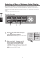
Selecting of Max or Minimum Value Display
Measurement result display is selectable among latest, max and minimum. If max
<PEAK> or minimum <VALLEY> has been selected here, continuous measurement is
to perform even though single measurement has been set. Lv determines max and min
values.
∗ Setting at the shipment from factory : latest
Setting
Operation Procedure
PEAK/
VALLEY
2
1.
3
1
Press ESC key when menu or target
value setting menu appears.
Measurement screen appears on LCD screen.
<ANGL> 1° VIEW
<SPD> AUTO
>NO SYNC
Lv 15.61cd/m2 <<SYNC
LENS>STANDARD
<MEM> AUTO NUM
x 0.4125
<MEMORY DATA>
y 0.4429
CH00: < DEFAULT>
<MODE> CONT.
[ SFT]
2.
Make sure that [ ] appears on left
bottom indicating this instrument
has not been set for SHIFT mode.
If [ S F T ] appear s instead, it means that
instrument is to operate in SHIFT mode. Press
SHIFT key to cancel SHIFT mode.
44
[ 2° ]
M003:
Lv
x
y
0.54
0.4004
0.4123
3.
Press PEAK/VALLEY key to show
measurement mode to select.
<MODE> CONT.
[ SFT ]
Latest measurement value also appears on LCD
screen in case that <PEAK> or <VALLEY> has
been selected.
<ANGL> 1° VIEW
<SPD> AUTO
>NO SYNC
Lv 15.61cd/m2 <<SYNC
LENS>STANDARD
<MEM> AUTO NUM
x 0.4125
<MEMORY DATA>
y 0.4429
CH00: < DEFAULT>
<PEAK>
[SFT]
Setting for normal screen/<PEAK>/<VALLEY>
shall be retained even after switching OFF (O).
[ 2° ]
M003:
Lv
x
y
15.61
0.4125
0.4429
<ANGL> 1° VIEW
<SPD> AUTO
>NO SYNC
Lv 15.61cd/m2 <<SYNC
LENS>STANDARD
<MEM> AUTO NUM
x 0.4123
<MEMORY DATA>
y 0.4435
CH00: < DEFAULT>
<VALLEY>
[SFT]
45
[ 2° ]
0.54
0.4004
0.4123
[ 2° ]
M003:
Lv
x
y
15.61
0.4125
0.4429
PEAK/
VALLEY
Latest measurement value shall appear as result
in normal, maximum in <PEAK>, and minimum in
<VALLEY> for continuous measurement.
M003:
Lv
x
y
Setting
Measurement screen switches in order of normal
→ <PEAK> → <VALLEY> → normal in SHIFT
while pressing PEAK/VALLEY key.
<ANGL> 1° VIEW
<SPD> AUTO
>NO SYNC
Lv 15.61cd/m2 <<SYNC
LENS>STANDARD
<MEM> AUTO NUM
x 0.4125
<MEMORY DATA>
y 0.4429
CH00: < DEFAULT>
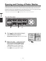
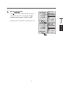
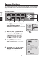
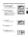
Opening and Closing of Finder Shutter
To prevent light from finder from badly influencing measurement, internal shutter of finder
is to close for every measurement. If observation through finder during measurement is
required, setting can be changed not to close finder shutter. In this case, light from finder
needs to be avoided by looking into finder during measurement.
∗ Setting at the shipment from factory :
(automatically closes for every measurement)
Setting
Operation Procedure
SUHUTTER
2
1.
1
3
Press ESC key when menu or target
value setting menu appears.
Measurement screen appears on LCD screen.
<ANGL> 1° VIEW
<SPD> AUTO
>NO SYNC
Lv 92.74cd/m2 <<SYNC
LENS>STANDARD
<MEM> AUTO NUM
x 0.4185
<MEMORY DATA>
y 0.4242
CH00: < DEFAULT>
<MODE> CONT.
[SFT ]
2.
Make sure that [ ] appears on left
bottom indicating this instrument
has not been set for SHIFT mode.
If [SFT] appears instead, it means that
instrument is to operate in SHIFT mode.
Press SHIFT key to cancel SHIFT mode.
46
[ 2° ]
M003:
Lv
x
y
1.04
0.3772
0.3663
3.
Press SHUTTER key.
<ANGL> 1° VIEW
<SPD> AUTO
>NO SYNC
Lv 92.74cd/m2 <<SYNC
LENS>STANDARD
<MEM> AUTO NUM
x 0.4185
<MEMORY DATA>
y 0.4242
CH00: < DEFAULT>
Icon [ ] indicating "automatically closes for
every measurement" switches to icon [ ]
meaning "always opens" in SHIFT mode.
[
]
[ 2° ]
1.04
0.3772
0.3663
<MODE> CONT.
[
47
]○
[ 2° ]
M003:
Lv
x
y
1.04
0.3772
0.3663
SUHUTTER
<ANGL> 1° VIEW
<SPD> AUTO
>NO SYNC
Lv 92.74cd/m2 <<SYNC
LENS>STANDARD
<MEM> AUTO NUM
x 0.4185
<MEMORY DATA>
y 0.4242
CH00: < DEFAULT>
Setting
Setting remains even after switching OFF (O).
<MODE> CONT.
M003:
Lv
x
y
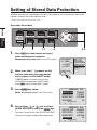
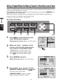
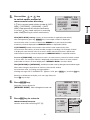
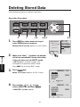
Setting of Stored Data Protection
Whether warning message appears or not is selectable for the case to store data in the
memory channel with measurement value.
∗ Setting at the shipment from factory : ON
Operation Procedure
Setting
DATA
PROTECT
2
1.
3
1, 7
6
Press ESC key when menu or target
value setting menu appears.
Measurement screen appears on LCD screen.
2.
4, 5
Make sure that [ ] appears on left
bottom indicating this instrument
has not been set for SHIFT mode.
CH00: < DEFAULT>
Lv 20.80cd/m2
x 0.4476
y 0.4477
<MODE>SINGLE
[
]
[ 2° ]
<ANGL> 1° VIEW
<SPD> AUTO
<SYNC>200.00Hz
<LENS>STANDARD
<MEM> AUTO NUM
<MEMORY DATA>
MOOO:(NO DATA)
Lv -----x -----y ------
If [SFT] appears instead, it means that
instrument is to operate in SHIFT mode.
Press SHIFT key to cancel SHIFT mode.
3.
<MENU> 2/4
OBJECTIVE LENS STANDARD
DISPLAY DIGITS
4 FIGURES
MEMORY MODE
AUTO NUM
DATA PROTECT
ON
Press MENU key twice..
Menu 2/4 screen appears on LCD screen.
[
4.
BREAK : [ESC]
[ 2° ]
<MENU> 2/4
OBJECTIVE LENS STANDARD
DISPLAY DIGITS
4 FIGURES
MEMORY MODE
AUTO NUM
DATA PROTECT
ON
Press either
or
key to select
[DATA PROTECT] and then ENTER key.
Inversion cursor moves from [DATA PROTECT]
to right to change setting for data protection.
[
48
]
]
BREAK : [ESC]
[ 2° ]
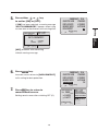
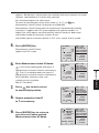
5.
If [ON] has been selected, a warning message
"OK TO OVERWRITE?" appears when trying
to store data to the directory with existing data .
[
]
BREAK : [ESC]
[ 2° ]
DATA
PROTECT
<ANGL> 1° VIEW
<SPD> AUTO
>200.00Hz
Lv 20.80cd/m2 <<SYNC
LENS>STANDARD
OK TO OVERWRITE?
<MEM> AUTO NUM
x 0.4476
<MEMORY DATA>
y 0.4477
CH02: < DEFAULT>
OK
: [ENTER] DATA)
MOOO:(NO
CANCEL :Lv
[ESC]
-----x -----<MODE>CONT.
y 0.3863
[
]
[ 2° ]
[OFF] proceeds with overwriting
without warning message.
6.
<MENU>
Press ENTER key.
OBJECTIVE LENS
DISPLAY DIGITS
MEMORY MODE
DATA PROTECT
Inversion cursor returns to [DATA PROTECT]
to fix setting for data protection.
[
7.
Press ESC key to return to
measurement screen.
]
Lv 20.80cd/m2
x 0.4476
y 0.4477
<MODE>SINGLE
[
49
]
2/4
STANDARD
4 FIGURES
AUTO NUM
ON
BREAK : [ESC]
[ 2° ]
CH00: < DEFAULT>
Setting remains even after switching OFF (O).
Setting
<MENU> 2/4
OBJECTIVE LENS
STANDARD
DISPLAY DIGITS
4 FIGURES
MEMORY MODE
AUTO NUM
DATA PROTECT
ON
Press either
or
key
to set for [ON] or [OFF].
[ 2° ]
<ANGL> 1° VIEW
<SPD> AUTO
<SYNC>200.00Hz
<LENS>STANDARD
<MEM> AUTO NUM
<MEMORY DATA>
MOOO:(NO DATA)
Lv -----x -----y ------
Setting of Update Method for Memory Channel to Store Measurement Value
There are 100 directories to store measurement value from M000 to M100 and each can
store one value, therefore 101 in total.
Here, whether measurement value is to store automatically or by pressing MEMORY key is
selectable for every measurement.
See p.50 for details on protection of stored data when data storage is to perform on
memory channel with another measurement value.
∗ Setting at the shipment from factory : AUTO NUNM
Setting
Operation Procedure
MEMORY
MODE
2
1.
3
1, 7
6
Press ESC key when menu or target
value setting menu appears.
Measurement screen appears on LCD screen.
2.
Make sure that [ ] appears on left
bottom indicating this instrument is
has not been set for SHIFT mode.
4, 5
CH00: < DEFAULT>
Lv 20.80cd/m2
x 0.4476
y 0.4477
<MODE>SINGLE
[
]
[ 2° ]
<ANGL> 1° VIEW
<SPD> AUTO
<SYNC> 200.00Hz
<LENS>STANDARD
<MEM> AUTO NUM
<MEMORY DATA>
MOOO:(NO DATA)
Lv -----x -----y ------
If [SFT] appears instead, it means that
instrument is to operate in SHIFT mode.
Press SHIFT key to cancel SHIFT mode.
3.
<MENU> 2/4
OBJECTIVE LENS STANDARD
DISPLAY DIGITS
4 FIGURES
MEMORY MODE
AUTO NUM
DATA PROTECT
ON
Press [MENU] key twice.
Menu 2/4 screen appears on LCD screen.
[
4.
BREAK : [ESC]
[ 2° ]
<MENU> 2/4
OBJECTIVE LENS STANDARD
DISPLAY DIGITS
4 FIGURES
MEMORY MODE
AUTO NUM
DATA PROTECT
ON
Press either
or
key to select
[MEMORY MODE] and then ENTER key.
Inversion cursor moves from
[MEMORY MODE] to right to change
update method of memory channel.
[
50
]
]
BREAK : [ESC]
[ 2° ]
5.
If
key is pressed, mode switches in order of [AUTO
NUM] → [AUTOSAVE] → [MAN NUM] → [AUTO
NUM]. If kept pressed, this switches continuously.
In case of
key, mode switches in reversing
order. Keep pressing to switch continuously.
[
]
BREAK : [ESC]
[ 2° ]
If [AUTOSAVE] is set, measurement value will be saved automatically after
measurement and memory channel number changes accordingly. For example, if M005
is displayed, measurement value is to store in M005 after measurement is performed
and number of memory channel displayed in <MEMORY DATA> is replaced to M006.
In case of [MAN NUM], measurement value is to store memory channel of which number
is shown then. For example, if M005 is displayed, measurement value is to store in M005
and nunber of memory channel displayed in <MEMORY DATA> remaines M005.
With [AUTO NUM] or [AUTOSAVE], and M100 has been used up, data goes back to M000 again.
When data storage is to perform on memory channel with another
measurement value, a warning message appears.
Warning message “OK TO OVERWRITE?” appears. If OK, press ENTER key, and if not, ESC key.
Setting is available not to display such message. See p.50.
Press ESC key to stop.
6.
<MENU> 2/4
OBJECTIVE LENS
STANDARD
DISPLAY DIGITS
4 FIGURES
MEMORY MODE
AUTOSAVE
DATA PROTECT
ON
Press ENTER key.
Inversion cursor returns to
[MEMORY MODE]. Now change has been set.
[
7.
Press ESC key to return to
measurement screen.
]
BREAK : [ESC]
[ 2° ]
CH00: < DEFAULT>
Lv 20.80cd/m2
x 0.4476
y 0.4477
remains even after switching OFF (O).
<MODE>SINGLE
[
51
]
[ 2° ]
<ANGL> 1° VIEW
<SPD> AUTO
<SYNC> 200.00Hz
<LENS>STANDARD
<MEM> AUTOSAVE
<MEMORY DATA>
MOOO:(NO DATA)
Lv -----x -----y ------
MEMORY
MODE
With [AUTO NUM] setting, memory channel number is replaced automatically
after storing data by pressing MEMORY key. For example, if M005 is displayed,
measurement value is to store in M005 after MEMORY key is pressed and number
of memory channel displayed in <MEMORY DATA> is replaced to M006.
Setting
<MENU> 2/4
OBJECTIVE LENS
STANDARD
DISPLAY DIGITS
4 FIGURES
MEMORY MODE
AUTO NUM
DATA PROTECT
ON
Press either
or
key
to switch update method of
measurement value directory.
Buzzer Setting
This instrument usually generates buzzer sound for key operation, but setting for buzzer
sound is switchable. Buzzer for measurement, operation, and error can be set independently.
∗ Setting at the shipment from factory : ON for MEASUREMENT, OPERATION, and WARNING
Operation Procedure
Setting
BUZZER
2
1.
3
1, 9
7
Press ESC key when menu or target
value setting menu appears.
Measurement screen appears on LCD screen.
4, 5, 6
CH00: < DEFAULT>
Lv 20.80cd/m2
x 0.4476
y 0.4477
<MODE>SINGLE
[
2.
]
[ 2° ]
<ANGL> 1° VIEW
<SPD> AUTO
<SYNC>200.00Hz
<LENS>STANDARD
<MEM> AUTO NUM
<MEMORY DATA>
MOOO:(NO DATA)
Lv -----x -----y ------
Make sure that [ ] appears on left
bottom indicating this instrument
has not been set for SHIFT mode.
If [SFT] appears instead, it means that
instrument is to operate in SHIFT mode.
Press SHIFT key to cancel SHIFT mode.
3.
<MENU> 3/4
SLEEP MODE
OFF
DATE & TIME
BUZZER
VERSION
Press [MENU] key three times.
Menu 3/4 screen appears on LCD screen.
[
4.
BREAK : [ESC]
[ 2° ]
<MENU> 3/4
SLEEP MODE
OFF
DATE & TIME
BUZZER
VERSION
Press either
or
key to select
[BUZZER] and then [ENTER] key.
<BUZZER> screen appears.
[
52
]
]
BREAK : [ESC]
[ 2° ]
5.
<BUZZER>
Press either
or
key to
select parameter to change
and then press ENTER key.
Inversion cursor moves from parameter name
to right to change setting for buzzer sound.
[
<BUZZER>
Press either
or
to set
for either [ON] or [OFF].
If [ON] is set for [MEASUREMENT],
short blip sounds after measurement, for
[OPERATION], short blip when measurement
button or related key is pressed, and for
[WARNING], repeated blip sounds for
erroneous key operation or error message.
7.
MEASUREMENT
OPERATION
WARNING
[
ON
ON
ON
BREAK : [ESC]
[ 2° ]
<BUZZER>
MEASUREMENT
OPERATION
WARNING
[
9.
]
Press ENTER key.
Inversion cursor returns to parameter
name to fix setting for buzzer sound.
8.
BREAK : [ESC]
[ 2° ]
]
ON
ON
ON
BREAK : [ESC]
[ 2° ]
Repeat procedures 6. and
7. as necessary.
Press ESC key twice to return
to measurement screen.
CH00: < DEFAULT>
Setting remains even after switching OFF (O).
Lv 20.80cd/m2
x 0.448
y 0.448
<MODE>SINGLE
[
53
]
[ 2° ]
<ANGL> 1° VIEW
<SPD> AUTO
<SYNC> 200.00Hz
<LENS>STANDARD
<MEM> AUTO NUM
<MEMORY DATA>
MOOO:(NO DATA)
Lv -----x -----y ------
BUZZER
6.
]
ON
ON
ON
Setting
MEASUREMENT
OPERATION
WARNING
Backlight ON/OFF
Whether turning backlight on LCD is ON or OFF is selectable.
∗ Setting at the shipment from factory : ON
Operation Procedure
Setting
BACK
LIGHT
2
1.
1
3
Press ESC key when menu or target
value setting menu appears.
Measurement screen appears on LCD screen.
CH00: < DEFAULT>
Lv 20.80cd/m2
x 0.4476
y 0.4477
<MODE>SINGLE
[
2.
Make sure that [ ] appears on left
bottom indicating this instrument
has not been set for SHIFT mode.
If [SFT] appears instead, it means that
instrument is to operate in SHIFT mode.
Press SHIFT key to cancel SHIFT mode.
3.
Press BACKLIGHT key.
If backlight has been on, it is switched
off, and off, switched on.
Setting remains even after switching OFF (O).
54
]
[ 2° ]
<ANGL> 1° VIEW
<SPD> AUTO
<SYNC>200.00Hz
<LENS>STANDARD
<MEM> AUTO NUM
<MEMORY DATA>
MOOO:(NO DATA)
Lv -----x -----y ------
Setting
BACK
LIGHT
55
Setting Sleep Mode
Sleep mode can be set for saving electric power consumption for the case that key has
not been operated or communication has not been done for more than 30 minutes.
∗ Setting at the shipment from factory : OFF
Operation Procedure
Setting
SLEEP
MODE
2
1.
3
1, 7
4, 6
Press ESC key when menu or target
value setting menu appears.
Measurement screen appears on LCD screen.
5
CH00: < DEFAULT>
Lv 20.80cd/m2
x 0.4476
y 0.4477
<MODE>SINGLE
[
2.
]
[ 2° ]
<ANGL> 1° VIEW
<SPD> AUTO
<SYNC>200.00Hz
<LENS>STANDARD
<MEM> AUTO NUM
<MEMORY DATA>
MOOO:(NO DATA)
Lv -----x -----y ------
Make sure that [ ] appears on left
bottom indicating this instrument
has not been set for SHIFT mode.
If [SFT] appears instead, it means that
instrument is to operate in SHIFT mode.
Press SHIFT key to cancel SHIFT mode.
3.
<MENU> 3/4
SLEEP MODE
OFF
DATE & TIME
BUZZER
VERSION
Press MENU key three times.
Menu 3/4 screen appears on LCD screen.
[
4.
BREAK : [ESC]
[ 2° ]
<MENU> 3/4
SLEEP MODE
OFF
DATE & TIME
BUZZER
VERSION
Press ENTER key.
Inversion cursor moves from [SLEEP MODE]
to right to change setting for sleep mode.
[
56
]
]
BREAK : [ESC]
[ 2° ]
5.
If [ON] is set, this instrument operates in sleep
mode when key operation or communication
has not been done for more than 30 minutes.
"SLEEP MODE" appears on LCD in sleep mode.
[
]
BREAK : [ESC]
[ 2° ]
SLEEP
MODE
SLEEP MODE
If measurement button or any key is pressed,
original screen appears after "PLEASE WAIT".
When“ PLEASE WAIT...” appears, do not
switch OFF. Doing so may break stored data.
<ANGL> 1° VIEW
<SPD> AUTO
>200.00Hz
Lv ------cd/m2 <<SYNC
LENS>STANDARD
<MEM> AUTO NUM
x 0.4476
<WAIT...
MEMORY DATA>
PLEASE
y 0.4477
CH02: < DEFAULT>
<MODE>SINGLE
[
6.
]
[ 2° ]
MOOO:(NO DATA)
Lv -----x 0.4155
y 0.4242
<MENU> 3/4
SLEEP MODE
ON
DATE & TIME
BUZZER
VERSION
Press ENTER key.
Inversion cursor returns
to [SLEEP MODE] to fix setting.
[
7.
Setting
<MENU> 3/4
SLEEP MODE
ON
DATE & TIME
BUZZER
VERSION
Press either
or
to set
either for [ON] or [OFF].
Press ESC key to return to
measurement screen.
]
BREAK : [ESC]
[ 2° ]
CH00: < DEFAULT>
Setting remains even after switching OFF (O).
Lv 20.80cd/m2
x 0.448
y 0.448
<MODE>SINGLE
[
57
]
[ 2° ]
<ANGL> 1° VIEW
<SPD> AUTO
<SYNC> 200.00Hz
<LENS>STANDARD
<MEM> AUTO NUM
<MEMORY DATA>
MOOO:(NO DATA)
Lv -----x -----y ------
Setting Internal Clock
This instrument is equipped with internal clock to record measurement time.
Although measurement date and time are not indicated in this instrument, one can be
output together with measurement value when this unit is controlled with PC.
If used with either standard accessory data management software CS-S10w Standard or
optional CS-S10w Professional, measurement time is to display together with measurement value.
Setting
∗ Internal clock adjustment has been completed before shipment form factory.
Operation Procedure
DATE &
TIME
6
2
1.
3
1, 9
4, 5
8
Press ESC key when menu or target
value setting menu appears.
Measurement screen appears on LCD screen.
CH00: < DEFAULT>
Lv 20.80cd/m2
x 0.4476
y 0.4477
<MODE>SINGLE
[
2.
]
[ 2° ]
<ANGL> 1° VIEW
<SPD> AUTO
<SYNC>200.00Hz
<LENS>STANDARD
<MEM> AUTO NUM
<MEMORY DATA>
MOOO:(NO DATA)
Lv -----x -----y ------
Make sure that [ ] appears on left
bottom indicating this instrument
has been set for SHIFT mode.
If [SFT] appears instead, it means that
instrument is to operate in SHIFT mode.
Press SHIFT key to cancel SHIFT mode.
3.
<MENU> 3/4
SLEEP MODE
OFF
DATE & TIME
BUZZER
VERSION
Press MENU key three times.
Menu 3/4 screen appears on LCD screen.
[
58
]
BREAK : [ESC]
[ 2° ]
4.
< DATE & TIME > screen appears.
[
Press either
or
set arbitrary value.
<DATE & TIME>
to
key for larger number. If kept pressed,
value continuously increases.
key for smaller number. If kept pressed,
value continuously becomes small.
6.
SLEEP MODE
DATE &2005Y/01M/01D
TIME
BUZZER 00:00:00
VERSION
[
Year range available to set is 2000 to 2099. If you
enter month and day that do not exist in calendar,
error occurs. Time range available to set is 00:00:00
to 23:59:59. If you enter incorrect time, error occurs.
Press ESC key to stop.
SLEEP MODE
DATE &2005Y/02M/01D
TIME
BUZZER 15:52:00
VERSION
[
[
BREAK : [ESC]
[ 2° ]
]
BREAK : [ESC]
[ 2° ]
CH00: < DEFAULT>
Lv 20.80cd/m2
x 0.448
y 0.448
<MODE>SINGLE
[
59
OFF
<MENU> 3/4
SLEEP MODE
OFF
DATE & TIME
BUZZER
VERSION
Press [ENTER] key.
Press ESC key to return to
measurement screen.
]
OFF
BREAK : [ESC]
[ 2° ]
<DATE & TIME>
Repeat the procedures from
5. to 6. as necessary.
Menu 3/4 screen appears on LCD screen
indicating internal clock has been set.
9.
]
OFF
BREAK : [ESC]
[ 2° ]
SLEEP MODE
DATE &2005Y/01M/01D
TIME
BUZZER 00:00:00
VERSION
[
8.
]
<DATE & TIME>
Press
key to move cursor
to second digit position.
Cursor shall not move if unsettable
number has been entered.
7.
BREAK : [ESC]
[ 2° ]
]
[ 2° ]
<ANGL> 1° VIEW
<SPD> AUTO
<SYNC> 200.00Hz
<LENS>STANDARD
<MEM> AUTO NUM
<MEMORY DATA>
MOOO:(NO DATA)
Lv -----x -----y ------
DATE &
TIME
5.
]
Setting
<MENU> 3/4
SLEEP MODE
OFF
DATE & TIME
BUZZER
VERSION
Press either
or
to select
[DATE & TIME] and then ENTER key.
60
Measurement Preparation
61
Calibration
Calibration Channel
There are 21 calibration channels from CH00 to CH20.
Following settings are available for all channels.
(1) Correction coefficient of user calibration
(2) Target color
(3) CH ID name
These are commonly used among each measurement mode of Lvxy, Lvu’v’, LvT∆uv, XYZ,
and dominant wavelength in one channel.
CH00 is for measurement based upon KONICA MINOLTA SENSING’s calibration stan-
Measurement
Preparation
dard. Its calibration correction coefficient has been set and is unchangeable. Only target
color and CH ID name settings are available.
To switch calibration channel, press either
or
key in SHIFT mode to switch one appearing on LCD screen.
CH ID name can be given to each channel through key operation. CH ID name is shown
on LCD screen together with calibration channel.
62
User Calibration
User calibration indicates to set user’s original correction coefficients in calibration channel by setting calibration value (For Lv, x, and y or Lv, u’ and v’ or X, Y and Z) in this instrument.
Displayed and output values for every measurement are values corrected with this correction coefficient unexceptionally.
Following calibration is available based on coefficient set by user.
(1) Difference in instrument readings due to difference between CIE 1931 color-matching
functions and spectral sensitivity.
(2) Difference in instrument readings between units if multiple numbers of this unit are
used.
This instrument employs monocalibration for user calibration. Accurate measurement
can be performed at luminance and chromaticity around calibration light source.
User calibration can be applied to every channel except for CH00.
KONICA MINOLTA SENSING’s correction coefficient has been set in all channels including CH00 by the time of shipment.
This shall restore if user calibration is reset.
Color on which user calibration is based is to set as target color in the same calibration
channel.
Target color serves as reference to determine how measured color deviates from reference.
User calibration can be done through either of following methods.
(1) Measurement
(2) Select from stored data
(3) Copy from other calibration channel
63
Measurement
Preparation
If you obtain calibration value by measuring a calibration light source with a prototype
standard, set the prototype standard and CS-200 in the same position and angle as
for the calibration light source and measure the same area. If measurement conditions
with the prototype standard and with CS-200 are different, you fail to perform correct
caliblation.
Keep calibration light source as stable as possible with fixed voltage power source
during measurement.
Implementing User Calibration
User calibration cannot be conducted in calibration channel CH00.
(CH00 serves as calibration channel for measurement based on KONICA MINOLTA
SENSING’s calibration standard.)
When user calibration is performed in the calibration channel for which target color has
already been set, previous target color is cancelled.
These are commonly used among each color space of Lvxy, Lvu’v’, LvT∆uv, XYZ, and
dominant wavelength in one channel.
Operation Procedure
Measurement CH
Preparation SETTING
5, 7
2
1.
3
1, 10
4, 9
5
4, 6
Press ESC key when menu or target
value setting menu appears.
Measurement screen appears on LCD screen.
2.
3.
Press SHIFT key to switch
to SHIFT mode.
<ANGL> 1° VIEW
<SPD> AUTO
>NO SYNC
Lv ------cd/m2 <<SYNC
LENS>STANDARD
<
MEM
>
AUTO NUM
x -----<
MEMORY DATA>
y ------
CH01: < DEFAULT>
[SFT] appears on left bottom indicating
this instrument is to operate in SHIFT
mode. Or make sure that [SFT] appears on
left bottom indicating that this instrument
has been operated in SHIFT mode.
Press either
or
key to
switch calibration channel and
select one for user calibration.
<MODE>SINGLE
[ SFT]
[ 2° ]
<ANGL> 1° VIEW
<SPD> AUTO
Lv ------cd/m2<SYNC>NO SYNC
<LENS>STANDARD
<MEM> AUTO NUM
x -----<MEMORY DATA>
y ------
CH01: < DEFAULT>
<MODE>SINGLE
[ SFT ]
64
M000 :(NO DATA)
Lv -----x -----y ------
[ 2° ]
M000 :(NO DATA)
Lv -----x -----y ------
4.
Press SHIFT key to cancel SHIFT mode.
<ANGL> 1° VIEW
<SPD> AUTO
>NO SYNC
Lv ------cd/m2 <<SYNC
LENS>STANDARD
<MEM> AUTO NUM
x -----<MEMORY DATA>
y ------
CH01: < DEFAULT>
<MODE>SINGLE
[
5.
[ 2° ]
<MENU>
Press MENU key.
CH SETTING
MEAS MODE
SYNC MODE
DELETE
Menu 1/4 screen appears on LCD screen.
Press either
or
key to select
USER CAL and then ENTER key.
< USER CAL > screen appears.
BREAK : [ESC]
[ 2° ]
<CH SETTING >
CH01: < DEFAULT>
USER CAL
CH ID NAME
CH COPY
CH RESET
[
Continues to the following page.
(1) Through measurement (p.66 to 67)
(2) Through selection from saved data (p.68 to 69)
(3) Copy from other calibration channel (p.70 to 71)
65
]
BREAK:[ESC]
]
[ 2° ]
1/4
SINGLE
Measurement CH
Preparation SETTING
[
6.
]
M000 :(NO DATA)
Lv -----x -----y ------
continuation from a p.64, 65.
13
99
16
11, 15
7, 12
(1) Through measurement
Measurement
Preparation USER CAL
7.
Press either
or
key to select
[USER CAL] and then ENTER key.
< USER CAL DATA> screen appears.
<CH SETTING >
CH01: < DEFAULT>
USER CAL
CH ID NAME
CH COPY
CH RESET
[
8.
Use close-up lens, select measuring
angle, adjust finder diopter and focus.
For more details on each operation, see p.88.
Use light source of which luminance and
chromaticity are known on object.
9.
Press COLOR key in SHIFT mode,
and select color space.
Select same color space as calibration value
to be entered in procedures from 12 to 13.
BREAK:[ESC]
]
[ 2° ]
<ANGL> 1° VIEW
<SPD> AUTO
<SYNC>NO SYNC
Lv ------cd/m2 <LENS>STANDARD
<MEM> AUTO NUM
x ------
<USER CAL DATA>
CH01:<DEFAULT>
y ------
SELECT MEH DATA
OR MEASURE.
NEXT : [ENTER]
[
]
[ 2° ]
to start measurement.
Now starts measurement.
This measurement is performed with correction
coefficient (CH00) based upon KONICA
MINOLTA SENSING's calibration standard.
Measurement value appears on
<CURRENT DATA> part of LCD screen
after measurement is completed.
After measurement, do not switch OFF
until measurement value appears.
Doing so may break stored data.
66
Lv -----x -----y ------
<ANGL> 1° VIEW
<SPD> AUTO
<SYNC>NO SYNC
Lv ------cd/m2 <LENS>STANDARD
<MEM> AUTO NUM
x ------
<USER CAL DATA>
CH01:<DEFAULT>
y ------
SELECT MEH DATA
OR MEASURE.
NEXT : [ENTER]
[ SFT]
[ 2° ]
10. Press measurement button
<HOLD DATA>
<HOLD DATA>
Lv -----x -----y ------
<ANGL> 1° VIEW
<SPD> AUTO
<SYNC>NO SYNC
Lv ------cd/m2 <LENS>STANDARD
<MEM> AUTO NUM
x ------
<USER CAL DATA>
CH01:<DEFAULT>
y ------
SELECT MEH DATA
OR MEASURE.
NEXT : [ENTER]
[ SFT]
[ 2° ]
<CURRENT DATA>
Lv 90.30
x 0.4210
y 0.4128
11.
<ANGL> 1° VIEW
<SPD> AUTO
<SYNC>NO SYNC
Lv ------cd/m2 <LENS>STANDARD
<MEM> AUTO NUM
x ------
<USER CAL DATA>
CH01:<DEFAULT>
Press ENTER key.
Calibration entry screen appears.
y ------
SET CAL VALUE.
OK : [ENTER]
[ SFT]
[ 2° ]
12. Enter value for calibration.
(See p.71 for details on ‘Numerical value entry ranges’ )
13. Press
key to move cursor
to second digit position.
<ANGL> 1° VIEW
<SPD> AUTO
<SYNC>NO SYNC
Lv 9-----cd/m2 <LENS>STANDARD
<MEM> AUTO NUM
x ------
<USER CAL DATA>
CH01:<DEFAULT>
y ------
SET CAL VALUE.
OK : [ENTER]
[ SFT]
[ 2° ]
Press ESC key to stop.
Lv 90.30
x 0.4210
y 0.4128
<ANGL> 1° VIEW
<SPD> AUTO
<SYNC>NO SYNC
Lv 9-----cd/m2 <LENS>STANDARD
<MEM> AUTO NUM
x ------
SET CAL VALUE.
OK : [ENTER]
[ SFT]
[ 2° ]
necessary to enter calibration values
for Lv, x and y (or each value for
other color spaces) respectively.
<CURRENT DATA>
<USER CAL DATA>
CH01:<DEFAULT>
y ------
14. Repeat procedures from 12 to 13 as
Lv 90.30
x 0.4210
y 0.4128
<CURRENT DATA>
Lv 90.30
x 0.4210
y 0.4128
<ANGL> 1° VIEW
<SPD> AUTO
<SYNC>NO SYNC
Lv 90.03 cd/m2<LENS>STANDARD
x 0.4215 <MEM> AUTO NUM
<USER CAL DATA>
CH01:<DEFAULT>
y 0.4130
SET CAL VALUE.
OK : [ENTER]
[ SFT]
[ 2° ]
<CURRENT DATA>
Lv 90.30
x 0.4210
y 0.4128
<CH SETTING >
CH01: < DEFAULT>
USER CAL
CH ID NAME
CH COPY
CH RESET
15. Press ENTER key.
After“ PLEASE WAIT...” appears,
<CH SETTING> screen appears.
When“ PLEASE WAIT...” appears, do not
switch OFF. Doing so may break stored data.
16. Press ESC key twice to return
to measurement screen.
BREAK:[ESC]
[ SFT]
[ 2° ]
<ANGL> 1° VIEW
<SPD> AUTO
>NO SYNC
Lv ------cd/m2 <<SYNC
LENS>STANDARD
<MEM> AUTO NUM
x -----<MEMORY DATA>
y ------
CH01: < DEFAULT>
<MODE>SINGLE
[ SFT ]
67
[ 2° ]
M000 :(NO DATA)
Lv -----x -----y ------
Measurement USER CAL
Preparation
key: 0 to 9 in ascending order. K, M,
decimal point and space available. If kept
pressed, value continuously changes.
key: 9 to 0 descending order. K, M,
decimal point and space available. If kept
pressed, value continuously changes.
K and M show x103 and x10 6 respectively.
<CURRENT DATA>
continuation from a p.64, 65.
12
9 9
15
10, 14
7, 8, 11
(2) Through selection from saved data
Measurement
Preparation USER CAL
7.
Press either
or
key to select
[USER CAL] and then ENTER key.
< USER CAL DATA> screen appears.
<CH SETTING >
CH01: < DEFAULT>
USER CAL
CH ID NAME
CH COPY
CH RESET
[
8.
Press either
or
to select stored data.
key
<ANGL> 1° VIEW
<SPD> AUTO
<SYNC>NO SYNC
Lv ------cd/m2 <LENS>STANDARD
<MEM> AUTO NUM
x ------
<USER CAL DATA>
CH01:<DEFAULT>
Please select data which was measured using CH00
(KONICA MINOLTA SENSING’s calibration standard.)
The data are considered to have been calculated using CH00 (KONICA
MINOLTA SENSING’s calibration standard) without compensation coefficients for user calibration, even if data measured using a calibration channel
other than CH00 are selected. Because of this, when existing data measured
using a calibration channel other than CH00 are selected for performing
user calibration, user calibration cannot be performed properly.
9.
BREAK:[ESC]
]
[ 2° ]
Press COLOR key in SHIFT mode,
and select color space.
Select same color space as calibration value
to be entered in procedures from 11 to 13.
10. Press ENTER key.
<MEMORY DATA>
M002 :
SELECT MEH DATA
Lv 100.76
OR MEASURE.
x 0.3945
NEXT : [ENTER]
y 0.3998
[
]
[ 2° ]
y ------
<ANGL> 1° VIEW
<SPD> AUTO
<SYNC>NO SYNC
Lv ------cd/m2 <LENS>STANDARD
<MEM> AUTO NUM
x ------
<USER CAL DATA>
CH01:<DEFAULT>
<MEMORY DATA>
M002 :
SELECT MEH DATA
Lv 100.76
OR MEASURE.
x 0.3945
NEXT : [ENTER]
y 0.3998
[ SFT]
[ 2° ]
y ------
<ANGL> 1° VIEW
<SPD> AUTO
<SYNC>NO SYNC
Lv ------cd/m2 <LENS>STANDARD
<MEM> AUTO NUM
x ------
<USER CAL DATA>
CH01:<DEFAULT>
Calibration entry screen appears.
y ------
SET CAL VALUE.
OK : [ENTER]
[ SFT]
[ 2° ]
68
<MEMORY DATA>
M002 :
Lv 100.76
x 0.3945
y 0.3998
11. Enter value for calibration.
key: 0 to 9 in ascending order. K, M,
decimal point and space available. If kept
pressed, value continuously changes.
key: 9 to 0 descending order. K, M,
decimal point and space available. If kept
pressed, value continuously changes.
K and M show x103 and x10 6 respectively.
(See p.71 for details on ‘Numerical value entry ranges’ )
key to move cursor
to second digit position.
Lv 1-----cd/m2
x -----y -----SET CAL VALUE.
OK : [ENTER]
[ SFT]
[ 2° ]
<USER CAL DATA>
CH01:<DEFAULT>
Lv 1-----cd/m2
x -----y -----SET CAL VALUE.
OK : [ENTER]
[ SFT]
[ 2° ]
13. Repeat procedures from 10 to 11
as necessary to enter calibration
values for Lv, x, and y respectively.
Press ESC key to stop.
<USER CAL DATA>
CH01:<DEFAULT>
After“ PLEASE WAIT...” appears,
<CH SETTING> screen appears.
When“ PLEASE WAIT...” appears, do not
switch OFF. Doing so may break stored data.
15. Press ESC key twice to return
<MEMORY DATA>
M002 :
Lv 100.76
x 0.3945
y 0.3998
<ANGL> 1° VIEW
<SPD> AUTO
<SYNC>NO SYNC
<LENS>STANDARD
<MEM> AUTO NUM
<MEMORY DATA>
M002 :
Lv 100.76
x 0.3945
y 0.3998
<ANGL> 1° VIEW
<SPD> AUTO
<SYNC>NO SYNC
<LENS>STANDARD
<MEM> AUTO NUM
Lv 100.77cd/m2
x 0.3945 <MEMORY DATA>
y 0.4000 M002 :
SET CAL VALUE.
OK : [ENTER]
[ SFT]
[ 2° ]
14. Press ENTER key.
<ANGL> 1° VIEW
<SPD> AUTO
<SYNC>NO SYNC
<LENS>STANDARD
<MEM> AUTO NUM
Lv
x
y
100.76
0.3945
0.3998
<CH SETTING >
CH01: < DEFAULT>
USER CAL
CH ID NAME
CH COPY
CH RESET
BREAK:[ESC]
[ SFT]
[ 2° ]
<ANGL> 1° VIEW
<SPD> AUTO
>NO SYNC
Lv ------cd/m2 <<SYNC
LENS>STANDARD
<MEM> AUTO NUM
x ------
CH01: < DEFAULT>
to measurement screen.
y ------
<MODE>SINGLE
[ SFT]
69
[ 2° ]
<MEMORY DATA>
M002 :
Lv 100.76
x 0.3945
y 0.3998
Measurement USER CAL
Preparation
12. Press
<USER CAL DATA>
CH01:<DEFAULT>
continuation from a p.64, 65.
11
9
7, 8
(3) Copy from other calibration channel
Measurement
Preparation USER CAL
7.
Press either
or
key to select
[CH COPY] and then ENTER key.
< COPY TO ??> screen appears.
<CH SETTING >
CH02: < DEFAULT>
USER CAL
CH ID NAME
CH COPY
CH RESET
[
8.
Press either
or
key to select
calibration channel to copy from.
To change calibration channel to copy to, press
SHIFT key to switch to SHIFT mode or press
or
key to select calibration channel to copy to.
Once copied, calibration channel to
copy to cannot be returned to previous
status before coping. Make sure to check
channel number before copying.
BREAK:[ESC]
]
[ 2° ]
<COPY TO>
CH02:<DEFAULT>
Lv -----x -----y ------
<SOURCE>
CH01 :
Lv 100.76
OK
: [ENTER]
x 0.3945
CANCEL : [ESC]
y 0.3998
[
]
[ 2° ]
OK TO COPY ?
<COPY TO>
CH02 :<DEFAULT>
Lv -----x -----y ------
<SOURCE>
CH01 :
Lv 100.76
OK
: [ENTER]
x 0.3945
CANCEL : [ESC]
y 0.3998
[ SFT]
[ 2° ]
OK TO COPY ?
9.
Press ENTER key.
After“ PLEASE WAIT...” appears and the
value is copied,<COPY TO> screen appears.
When“ PLEASE WAIT...” appears, do not
switch OFF. Doing so may break stored data.
70
<COPY TO>
CH02 :<DEFAULT>
Lv 100.76
x 0.3945
y 0.3998
<SOURCE>
CH01 :
Lv 100.76
OK
: [ENTER]
x 0.3945
CANCEL : [ESC]
y 0.3998
[ SFT]
[ 2° ]
OK TO COPY ?
10. You can return to procedure 8 and
continue copying other channel.
Note that original calibration channel
appears when you return to measurement
screen in procedure 11.
<ANGL> 1° VIEW
<SPD> AUTO
>NO SYNC
Lv ------cd/m2 <<SYNC
LENS>STANDARD
<MEM> AUTO NUM
x -----<MEMORY DATA>
y ------
CH02 : < DEFAULT>
11. Press ESC key three times to
return to measurement screen.
[ SFT ]
[ 2° ]
Numerical value entry ranges
Numerical value entry ranges are shown below.
All conditions should be satisfied.
0< x < 1, and
0< y < 1, and
0< x +y 1, and
0< X 99999000000, and
0< Y 99999000000, and
0 Z 99999000000
<ANGL> 1° VIEW
<SPD> AUTO
<SYNC>NO SYNC
Lv 9-----cd/m2 <LENS>STANDARD
<MEM> AUTO NUM
x ------
<USER CAL DATA>
CH01:<DEFAULT>
y ------
SET CAL VALUE.
OK : [ENTER]
[ SFT]
[ 2° ]
Characters following K and M are ignored.
(“1.0K3” is interpreted as “1.0K”, i.e. 1000.)
Characters following second decimal point are ignored.
(“1.2.3” is interpreted as “1.2”.)
Characters following space between numbers are ignored.
(“1.2_3” is interpreted as “12”.)
71
<CURRENT DATA>
Lv 90.30
x 0.4210
y 0.4128
Measurement USER CAL
Preparation
<MODE>SINGLE
M000 :(NO DATA)
Lv -----x -----y ------
Reset User Calibration
User calibration can be reset channel by channel. KONICA MINOLTA SENSING’s calibration is to apply to channel for which user calibration has been reset. Also, target color
and ID name settings in the channel are to delete.
Operation Procedure
Measurement
Preparation CH RESET
2, 4
1.
5
1, 10
6, 7, 8
Press ESC key when menu or target
value setting menu appears.
3, 6, 7
<ANGL> 1° VIEW
<SPD> AUTO
> 60.00Hz
Lv ------cd/m2 <<SYNC
LENS>STANDARD
<MEM> AUTO NUM
x -----<MEMORY DATA>
y ------
CH00: < DEFAULT>
Measurement screen appears on LCD screen.
<MODE>SINGLE
[
2.
Press SHIFT key to switch
to SHIFT mode.
]
[ 2° ]
<ANGL> 1° VIEW
<SPD> AUTO
> 60.00Hz
Lv ------cd/m2 <<SYNC
LENS>STANDARD
<MEM> AUTO NUM
x -----<MEMORY DATA>
y ------
CH00 : < DEFAULT>
[SFT] appears on left bottom. Or make sure
that [SFT] appears on left bottom indicating that
this instrument has been operated in SHIFT mode.
<MODE>SINGLE
[ SFT]
3.
4.
M000 :(NO DATA)
Lv -----x -----y ------
Press either
or
key to switch
calibration channel and select one for
which user calibration is to reset.
Once reset, calibration channel to copy
to cannot be returned to previous status
before resetting. Make sure to check
channel number before copying.
Press SHIFT key to cancel SHIFT mode.
[ 2° ]
<ANGL> 1° VIEW
<SPD> AUTO
Lv ------cd/m2<SYNC> 60.00Hz
<LENS>STANDARD
<MEM> AUTO NUM
x -----<MEMORY DATA>
y ------
CH01: < DEFAULT>
<MODE>SINGLE
[ SFT ]
[ 2° ]
M000 :(NO DATA)
Lv -----x -----y ------
<ANGL> 1° VIEW
<SPD> AUTO
> 60.00Hz
Lv ------cd/m2 <<SYNC
LENS>STANDARD
<MEM> AUTO NUM
x -----<MEMORY DATA>
y ------
CH01: < DEFAULT>
<MODE>SINGLE
[
72
M000 :(NO DATA)
Lv -----x -----y ------
]
[ 2° ]
M000 :(NO DATA)
Lv -----x -----y ------
5.
<MENU> 1/4
CH SETTING
MEAS MODE
SINGLE
SYNC MODE
DELETE
Press MENU key.
Menu 1/4 screen appears on LCD screen.
[
6.
Press either
or
key to select
<CH SETTING> and then ENTER key.
< CH SETTING> screen appears.
]
<CH SETTING >
CH01: < DEFAULT>
USER CAL
CH ID NAME
CH COPY
CH RESET
Press either
or
key to select
[CH RESET] and then ENTER key.
< RESET > screen appears.
<CH SETTING >
CH01: < DEFAULT>
USER CAL
CH ID NAME
CH COPY
CH RESET
[
8.
Press ENTER key.
After“ PLEASE WAIT...” appears and it
is reset, <RESET> screen appears.
When“ PLEASE WAIT...” appears, do not
switch OFF. Doing so may break stored data.
9.
BREAK:[ESC]
]
[ 2° ]
Measurement CH RESET
Preparation
[
7.
BREAK : [ESC]
[ 2° ]
BREAK:[ESC]
]
[ 2° ]
<RESET>
CH01:
Lv 100.77
x 0.3945
y 0.4000
OK TO RESET
THIS CH ?
OK
: [ENTER]
CANCEL : [ESC]
[
]
[ 2° ]
As in procedure 3, you can switch
calibration channel to continue to
reset other calibration channel.
Note that original calibration channel
appears when you return to measurement
screen in procedure 10.
10. Press ESC key three times to
<ANGL> 1° VIEW
<SPD> AUTO
> 60.00Hz
Lv ------cd/m2 <<SYNC
LENS>STANDARD
<MEM> AUTO NUM
x -----<MEMORY DATA>
y ------
CH01: < DEFAULT>
return to measurement screen.
<MODE>SINGLE
[
73
]
[ 2° ]
M000 :(NO DATA)
Lv -----x -----y ------
Setting CH ID Name
CH ID name indicates name given to each calibration channel by entering characters.
CH ID name appears on LCD screen in measurement together with calibration channel.
It is helpful if for which object user calibration or target color setting has been done is
entered.
Available number of characters for entry: 9 max
Available character type for entry: A to Z, a to z, space, 0 to 9, symbol
Operation Procedure
Measurement CH ID
Preparation NAME
9
2, 4
1.
5
1, 12
1, 7, 11
Press ESC key when menu or target
value setting menu appears.
3, 6, 7, 8
<ANGL> 1° VIEW
<SPD> AUTO
> 60.00Hz
Lv ------cd/m2 <<SYNC
LENS>STANDARD
<MEM> AUTO NUM
x -----<MEMORY DATA>
y ------
CH01: < DEFAULT>
Measurement screen appears on LCD screen.
<MODE>SINGLE
[
2.
Press SHIFT key to switch
to SHIFT mode.
]
[ 2° ]
<ANGL> 1° VIEW
<SPD> AUTO
> 60.00Hz
Lv ------cd/m2 <<SYNC
LENS>STANDARD
<
MEM
>
AUTO NUM
x -----<
MEMORY DATA>
y ------
CH01: < DEFAULT>
[SFT] appears on left bottom. Or make sure that
[SFT] appears on left bottom indicating that this
instrument has been operated in SHIFT mode.
<MODE>SINGLE
[ SFT]
3.
M000 :(NO DATA)
Lv -----x -----y ------
Press either
key to switch
or
calibration channel and select
one for CH ID name setting.
[ 2° ]
<ANGL> 1° VIEW
<SPD> AUTO
Lv ------cd/m2<SYNC> 60.00Hz
<LENS>STANDARD
<MEM> AUTO NUM
x -----<MEMORY DATA>
y ------
CH01: < DEFAULT>
<MODE>SINGLE
[ SFT ]
74
M000 :(NO DATA)
Lv -----x -----y ------
[ 2° ]
M000 :(NO DATA)
Lv -----x -----y ------
4.
Press SHIFT key to cancel SHIFT mode.
<ANGL> 1° VIEW
<SPD> AUTO
> 60.00Hz
Lv ------cd/m2 <<SYNC
LENS>STANDARD
<MEM> AUTO NUM
x -----<MEMORY DATA>
y ------
CH01: < DEFAULT>
<MODE>SINGLE
[
5.
CH SETTING
MEAS MODE
SYNC MODE
DELETE
Press either
or
key to select
[CH SETTING] and then ENTER key.
< CH SETTING> screen appears.
< CH ID NAME > screen appears.
Enter CH ID name.
: A to Z in descending order and space. If
kept pressed, character switches continuously.
: Z to A in ascending order and space. If
kept pressed, character switches continuously.
Small alphabets, numerical values, and symbols
are also available. See p.79 for details.
75
BREAK:[ESC]
]
[ 2° ]
<CH SETTING >
CH01: < DEFAULT>
USER CAL
CH ID NAME
CH COPY
CH RESET
[
8.
BREAK : [ESC]
[ 2° ]
<CH SETTING >
CH01: < DEFAULT>
USER CAL
CH ID NAME
CH COPY
CH RESET
[
Press either
or
key to select
[CH ID NAME] and then ENTER key.
]
BREAK:[ESC]
]
[ 2° ]
<CH ID NAME >
CH01: < DEFAULT>
[(DEFAULT)] A
Lv -----x -----y -----OK
: [ENTER]
[
]
[ 2° ]
1/4
SINGLE
Measurement CH ID
Preparation NAME
[
7.
[ 2° ]
<MENU>
Press MENU key.
Menu 1/4 screen appears on LCD screen.
6.
]
MOOO:(NO DATA)
Lv -----x -----y ------
9.
Press
key to move cursor
to second digit position.
<CH ID NAME >
CH01: < DEFAULT>
[SDEFAULT) ] A
Lv -----x -----y -----OK
: [ENTER]
[
]
[ 2° ]
10. Repeat procedures from
8.
to
9.
<CH ID NAME >
CH01: < DEFAULT>
[SAMPLE )] A
as necessary.
Press ESC key to stop.
Lv -----x -----y -----OK
: [ENTER]
[
]
[ 2° ]
Measurement CH ID
Preparation NAME
11.
Press ENTER key.
After“ PLEASE WAIT...” appears and it is
reset, <CH SETTING> screen appears.
When“ PLEASE WAIT...” appears, do not
switch OFF. Doing so may break stored data.
<CH SETTING >
CH01: < SAMPLE >
USER CAL
CH ID NAME
CH COPY
CH RESET
[
12. Press ESC key two times to return
BREAK:[ESC]
]
[ 2° ]
<ANGL> 1° VIEW
<SPD> AUTO
> 60.00Hz
Lv ------cd/m2 <<SYNC
LENS>STANDARD
<MEM> AUTO NUM
x -----<MEMORY DATA>
y ------
CH01: < SAMPLE >
to measurement screen.
<MODE>SINGLE
[
76
]
[ 2° ]
MOOO:(NO DATA)
Lv -----x -----y ------
Entering Character
If you press SHIFT key to switch to SHIFT mode and then CHAR MODD key when
screen to enter calibration channel ID and measurement value ID of stored data in
appears, available character type for entry shifts in order of Capital Alphabet →
Small Alphabet → Numerical → Symbol → Capital Alphabet.
Either A , a , 1 , or # appears on the right of character entry area, depending
on character type.
Characters available to enter Mark
<CH ID NAME >
CH01: < DEFAULT>
[(DEFAULT)] A
Capital Alphabet
A to Z , S p a c e
OK
: [ENTER]
[
]
[ 2° ]
<CH ID NAME >
CH01: < DEFAULT>
[(DEFAULT)] a
Small Alphabet
a to z, Space
Lv -----x -----y -----OK
: [ENTER]
[
]
[ 2° ]
<CH ID NAME >
CH01: < DEFAULT>
[(DEFAULT)] 1
Numerical
0 to 9
Lv -----x -----y -----OK
: [ENTER]
[
]
[ 2° ]
<CH ID NAME >
CH01: < DEFAULT>
[(DEFAULT)] #
Lv -----x -----y ------
Symbol
Space ! ” # $ % & ’ ( ) ∗ + , - . / : ;
< = > ? @ [ ] ^ _ ‘ { | }
OK
: [ENTER]
[
]
[ 2° ]
77
Measurement CH ID
Preparation NAME
Lv -----x -----y ------
Setting and Changing Target Color
Target color
Target color serves as reference for measurement of deviation of measured color from
reference. It can be set channel by channel. Setting methods are as follows:
(1) User calibration: Calibration value is simultaneously set as target color in user calibration.
(2) Measurement
(3) Select from stored data
(4) Enter numerical value
Previously set target color is to erase since target color setting is performed at the same
time as entry of user calibration correction coefficient.
Measurement
Preparation
Previously set target color should be replaced with and changed to another one to
change. User calibration correction coefficient shall not be influenced despite of target
color change.
Target color is commonly used among each measurement mode of Lvxy, Lvu’v’, LvT(d)uv,
XYZ, and dominant wavelength in one calibration channel.
No target color has been set for calibration channel without target color set by the time
of shipment from factory. Only “------” appears.
In the target setting screen, the target data for a channel other than the displayed channel
may be displayed. If this occurs, use the up/down keys to temporarily select a different
channel, and then return to the desired channel. The correct data will then be displayed.
When the display is switched repeatedly between the <TARGET> screen and <USER CAL DATA> screen while
checking data, the target data shown in the <TARGET> screen may be the data for a different target channel
than the channel number which is shown. For example, if the channel is set to CH01 in the <TARGET> screen,
and then the screen is changed to the <USER CAL DATA> screen and CH02 is selected, and then the screen
is changed back to the <TARGET> screen, the channel display continues to show CH02 but the displayed
data are actually the data for CH01.
78
(1) Through user calibration
Calibration value is simultaneously set as target color if user calibration is performed in
calibration channel from CH01 to CH20. No further target color setting is needed if target
color has been fixed for calibration channel.
Follow below next page only when target color set in CH01 to CH20 needs to change or
target color is needed to set in KONICA MINOLTA SENSING’s calibration standard CH00.
Measurement
Preparation
79
(2) Through measurement
Operation Procedure
4
Measurement
Preparation TARGET
1.
2
1, 8
7
Press ESC key when menu or target
value setting menu appears.
3
<ANGL> 1° VIEW
<SPD> AUTO
>NO SYNC
Lv ------cd/m2 <<SYNC
LENS>STANDARD
<MEM> AUTO NUM
x -----<MEMORY DATA>
y ------
CH01: < DEFAULT>
Measurement screen appears on LCD screen.
<MODE>SINGLE
[
2.
]
[ 2° ]
MOOO:(NO DATA)
Lv -----x -----y ------
Press SHIFT key to switch
to SHIFT mode.
[SFT] appears on left bottom. Or make sure that
[SFT] appears on left bottom indicating that this
instrument has been operated in SHIFT mode.
3.
4.
Press either
or
key to switch
calibration channel and select one
for which target color is to set.
Once target color is set, calibration
channel cannot be returned to previous
status before setting. Make sure to check
channel number before overwriting.
<ANGL> 1° VIEW
<SPD> AUTO
>NO SYNC
Lv ------cd/m2 <<SYNC
LENS>STANDARD
<
MEM
>
AUTO NUM
x -----<MEMORY DATA>
y ------
CH01: < DEFAULT>
<MODE>SINGLE
[ SFT]
[ 2° ]
M000 :(NO DATA)
Lv -----x -----y ------
<ANGL> 1° VIEW
<SPD> AUTO
<SYNC>NO SYNC
Lv ------cd/m2 <LENS>STANDARD
<MEM> AUTO NUM
x ------
Press TARGET key.
<TARGET>
CH01:Display*1
<TARGET> screen appears.
y ------
SELECT MEH DATA
OR MEASURE.
NEXT : [ENTER]
[ SFT]
[ 2° ]
80
<HOLD DATA>
Lv -----x -----y ------
5.
Use close-up lens, select measuring
angle, adjust finder diopter and focus.
For more details on each operation, see p.88.
6.
Press Measurement button
to start measurement.
<TARGET>
CH01:Display*1
Now starts measurement.
Measurement value appears on <HOLD DATA>
of LCD after measurement is completed.
7.
Press ENTER key.
After“ PLEASE WAIT...” appears, measurement
value has been set as target color.
When“ PLEASE WAIT...” appears, do not
switch OFF. Doing so may break stored data.
Lv ------cd/m2
x -----<HOLD DATA>
y ------
SELECT MEH DATA
OR MEASURE.
NEXT : [ENTER]
[ SFT]
[ 2° ]
<TARGET>
CH01:Display*1
<MODE>SINGLE
[ 2° ]
CH01: < DEFAULT>
measurement screen.
Lv ------cd/m2
x -----y -----<MODE>SINGLE
[ SFT]
81
90.41
0.4174
0.4237
<ANGL> 1° VIEW
<SPD> AUTO
<SYNC> 200.00Hz
<LENS>STANDARD
<MEM> AUTO NUM
Lv 90.41cd/m2
x 0.4174
<HOLD DATA>
y 0.4237
Lv
90.41
[ SFT]
8. Press ESC key to return to
Lv
x
y
[ 2° ]
x
y
0.4174
0.4237
<ANGL> 1° VIEW
<SPD> AUTO
<SYNC>NO SYNC
<LENS>STANDARD
<MEM> AUTO NUM
<MEMORY DATA>
M000 :(NO DATA)
Lv -----x -----y ------
Measurement TARGET
Preparation
After measurement, do not switch OFF
until measurement value appears.
Doing so may break stored data.
This measurement is corrected with user
calibration value for selected calibration channel.
<ANGL> 1° VIEW
<SPD> AUTO
<SYNC>NO SYNC
<LENS>STANDARD
<MEM> AUTO NUM
(3) Through selection from saved data
Operation Procedure
4
Measurement
Preparation TARGET
1.
2, 5
1, 8
7
Press ESC key when menu or target
value setting menu appears.
3, 6
CH01: < DEFAULT>
Lv ------cd/m2
x -----y ------
Measurement screen appears on LCD screen.
<MODE>SINGLE
[
2.
]
[ 2° ]
<ANGL> 1° VIEW
<SPD> AUTO
<SYNC>NO SYNC
<LENS>STANDARD
<MEM> AUTO NUM
<MEMORY DATA>
M000 :(NO DATA)
Lv -----x -----y ------
Press SHIFT key to switch
to SHIFT mode.
[SFT] appears on left bottom. Or make sure that
[SFT] appears on left bottom indicating that this
instrument has been operated in SHIFT mode.
3.
4.
Press either
or
key to switch
calibration channel and select one
for which target color is to set.
Once target color is set, calibration
channel cannot be returned to previous
status before setting. Make sure to check
channel number before overwriting.
CH01: < DEFAULT>
Lv ------cd/m2
x -----y -----<MODE>SINGLE
[ SFT]
[ 2° ]
<ANGL> 1° VIEW
<SPD> AUTO
<SYNC>NO SYNC
<LENS>STANDARD
<MEM> AUTO NUM
<MEMORY DATA>
M000 :(NO DATA)
Lv -----x -----y ------
<ANGL> 1° VIEW
<SPD> AUTO
<SYNC>NO SYNC
Lv ------cd/m2 <LENS>STANDARD
<MEM> AUTO NUM
x -----<HOLD DATA>
y ------
Press TARGET key.
<TARGET>
CH01:Display*1
<TARGET> screen appears.
SELECT MEH DATA
OR MEASURE.
NEXT : [ENTER]
[ SFT]
[ 2° ]
82
Lv -----x -----y ------
5.
Press SHIFT key to cancel SHIFT mode.
<ANGL> 1° VIEW
<SPD> AUTO
<SYNC>NO SYNC
Lv ------cd/m2 <LENS>STANDARD
<MEM> AUTO NUM
x ------
<TARGET>
CH01 :Display*1
y ------
SELECT MEH DATA
OR MEASURE.
NEXT : [ENTER]
[
]
[ 2° ]
6.
<TARGET>
CH01:Display*1
<TARGET>
CH01:Display*1
Lv 90.78cd/m2
x 0.3872
y 0.3996
[
Press ESC key to return to
measurement screen.
BREAK:[ESC]
]
[ 2° ]
CH01: < DEFAULT>
Lv ------cd/m2
x -----y -----<MODE>SINGLE
[
83
]
[ 2° ]
M001:
x
y
90.78
0.3872
0.3996
<ANGL> 1° VIEW
<SPD> AUTO
<SYNC>NO SYNC
<LENS>STANDARD
<MEM> AUTO NUM
<MEMORY DATA>
M001:
x
y
90.78
0.3872
0.3996
<ANGL> 1° VIEW
<SPD> AUTO
<SYNC>NO SYNC
<LENS>STANDARD
<MEM> AUTO NUM
<MEMORY DATA>
M000 :(NO DATA)
Lv -----x -----y ------
Measurement TARGET
Preparation
Press ENTER key.
After“ PLEASE WAIT...” appears, selected
value has been set as target color.
When“ PLEASE WAIT...” appears, do not
switch OFF. Doing so may break stored data.
8.
Lv -----x -----y ------
<ANGL> 1° VIEW
<SPD> AUTO
<SYNC>NO SYNC
Lv 90.41cd/m2 <LENS>STANDARD
<MEM> AUTO NUM
x 0.4174
<MEMORY DATA>
y 0.4137
Press either
key
or
to select stored data.
SELECT MEH DATA
OR MEASURE.
NEXT : [ENTER]
[
]
[ 2° ]
7.
<HOLD DATA>
(4) By entering numerical value
Operation Procedure
7
4, 5
Measurement
Preparation TARGET
1.
2
1, 10
9
Press ESC key when menu or target
value setting menu appears.
3, 6
<ANGL> 1° VIEW
<SPD> AUTO
>NO SYNC
Lv ------cd/m2 <<SYNC
LENS>STANDARD
<MEM> AUTO NUM
x -----<MEMORY DATA>
y ------
CH01: < DEFAULT>
Measurement screen appears on LCD screen.
<MODE>SINGLE
2.
[
]
[ 2° ]
MOOO:(NO DATA)
Lv -----x -----y ------
Press SHIFT key to switch
to SHIFT mode.
[SFT] appears on left bottom. Or make sure that
[SFT] appears on left bottom indicating that this
instrument has been operated in SHIFT mode.
3.
4.
Press either
key to switch
or
calibration channel and select one
for which target color is to set.
Once target color is set, calibration
channel cannot be returned to previous
status before setting. Make sure to check
channel number before overwriting.
<ANGL> 1° VIEW
<SPD> AUTO
>NO SYNC
Lv ------cd/m2 <<SYNC
LENS>STANDARD
<
MEM
>
AUTO NUM
x -----<MEMORY DATA>
y ------
CH01: < DEFAULT>
<MODE>SINGLE
[ SFT ]
[ 2° ]
M000 :(NO DATA)
Lv -----x -----y ------
<ANGL> 1° VIEW
<SPD> AUTO
<SYNC>NO SYNC
Lv ------cd/m2 <LENS>STANDARD
<MEM> AUTO NUM
x -----<HOLD DATA>
y ------
Press TARGET key.
<TARGET>
CH01:Display*1
<TARGET> screen appears.
SELECT MEH DATA
OR MEASURE.
NEXT : [ENTER]
[ SFT]
[ 2° ]
84
Lv -----x -----y ------
5.
6.
Press TARGET key to go to
target color entry screen.
<TARGET>
CH01:Display*1
Enter target color in numerical value.
key: 0 to 9 in ascending
order. K, M, decimal point and
space available. If kept pressed,
value continuously changes.
Press
key to move the cursor
to second digit position.
SET CAL VALUE.
OK : [ENTER]
[ SFT]
[ 2° ]
<TARGET>
CH01:Display*1
Lv 9-----cd/m2
x -----y ------
<ANGL> 1° VIEW
<SPD> AUTO
<SYNC>NO SYNC
<LENS>STANDARD
<MEM> AUTO NUM
SET CAL VALUE.
OK : [ENTER]
[ SFT]
[ 2° ]
<TARGET>
CH01:Display*1
Lv 9-----cd/m2
x -----y ------
<ANGL> 1° VIEW
<SPD> AUTO
<SYNC>NO SYNC
<LENS>STANDARD
<MEM> AUTO NUM
SET CAL VALUE.
OK : [ENTER]
[ SFT]
[ 2° ]
8.
Repeat procedures from 6. to 7.
as necessary to enter target color
of Lv, x and y respectively.
Press ESC key to stop.
<TARGET>
CH01:Display*1
Lv 90.78 cd/m2
x -----y ------
<ANGL> 1° VIEW
<SPD> AUTO
<SYNC>NO SYNC
<LENS>STANDARD
<MEM> AUTO NUM
SET CAL VALUE.
OK : [ENTER]
[ SFT]
[ 2° ]
9.
Press ENTER key.
After“ PLEASE WAIT...” appears, entered
value has been set as target color.
When“ PLEASE WAIT...” appears, do not
switch OFF. Doing so may break stored data.
10. Press ESC key to return to
<TARGET>
CH01:Display*1
Lv 90.78 cd/m2
x 0.3545
y 0.3965
<ANGL> 1° VIEW
<SPD> AUTO
<SYNC>NO SYNC
<LENS>STANDARD
<MEM> AUTO NUM
SET CAL VALUE.
OK : [ENTER]
[ SFT]
[ 2° ]
<ANGL> 1° VIEW
<SPD> AUTO
>NO SYNC
Lv ------cd/m2 <<SYNC
LENS>STANDARD
<MEM> AUTO NUM
x -----<MEMORY DATA>
y ------
CH01: < DEFAULT>
measurement screen.
<MODE>SINGLE
[ SFT ]
85
[ 2° ]
M000 :(NO DATA)
Lv -----x -----y ------
Measurement TARGET
Preparation
7.
key: 9 to 0 descending order. K, M,
decimal point and space available. If kept
pressed, value continuously changes.
K and M show x103 and x10 6 respectively.
(See p.71 for details on ‘Numerical value entry ranges’ )
Lv ------cd/m2
x -----y ------
<ANGL> 1° VIEW
<SPD> AUTO
<SYNC>NO SYNC
<LENS>STANDARD
<MEM> AUTO NUM
86
Measurement
87
Measurement
Operation Procedure
1.
Decide whether you use close-up
lens (optional) or not according to
measuring object size and distance.
See the table below for details on measuring distance
and measuring area. If you set close-up lens, lens
type setting is required in this instrument. (see p.40)
Measuring distance and measuring area
(unit:mm)
Minimum measuring area Maximum measuring area Minimum measuring area Maximum measuring area Measuring area at 500 mm Measuring area at1000 mm
(Measuring angle) 1˚
0.2˚ 0.1˚
1˚
1.0
0.5
0.2˚ 0.1˚
1˚
0.2˚ 0.1˚
1˚
0.2˚ 0.1˚
1˚
0.2˚ 0.1˚
ø1.7
1˚
0.2˚ 0.1˚
∞
∞
∞
296
∞
8.5
Close-up Lens No.122
2.2
0.5
0.3
4.6
1.0
0.5
128
240
−
−
−
−
−
−
Close-up Lens No.107
0.8
0.2
0.1
1.1
0.3
0.2
43
52
−
−
−
−
−
−
Without a Close-Up Lens 4.7
ø0.9 ø17.7 ø3.6 ø1.8
∗Measuring distance is the distance from the front edge of the metal lens barrel or close-up lens ring.
2.
Slide measuring angle selector
according to size of object and select
either aperture1˚, 0.2˚, or 0.1˚.
∗ The measuring angle select is covered with holding cap
CS-A24 (see p.8) at shipment from factory.
Measurement
Pressing with finger cushion, slide
measuring angle selector slowly.
Do not operate measuring angle selector during
measurement. If measuring angle is switched during
measurement, you may fail to perform measurement
or to obtain correct measurement value.
3.
Rotate diopter adjustment ring on
finder for diopter adjustment.
Make sure that aperture (black circle indicating
measurement area) looks clear when
observing object through finder. (See p.17.)
4.
Rotate focus adjustment ring for
objective lens for that purpose.
Make sure that object around aperture looks
clear when observing object through finder.
Only measuring area for measuring object must
be placed in aperture. If extra area, which is
not measuring object, is included in aperture,
you cannot perform correct measurement.
88
0.1° 0.2° 1°
5.
Press ESC key when menu or target
value setting menu appears.
Lv ------cd/m2
x -----y ------
Measurement screen appears on LCD screen.
6.
Press measurement button.
Securely support this instrument so that
measuring object should not be removed from
aperture when pressing measurement button.
Lv value appears in finder. (Lv value (Y value
when observer angle is 10˚) appears in any
color space setting for LCD screen.)
Measurement result appears on LCD screen.
After measurement, do not switch OFF
until measurement value appears.
Doing so may break stored data.
<ANGL> 1° VIEW
<SPD> AUTO
<SYNC>200.00Hz
<LENS>STANDARD
<MEM> AUTO NUM
<MEMORY DATA>
CH01: < DEFAULT>
M000 : (NO DATA)
Lv -----x -----y ------
<MODE>SINGLE
[
]
[ 2° ]
<ANGL> 1° VIEW
<SPD> AUTO
<SYNC>200.00Hz
<LENS>STANDARD
<MEM> AUTO NUM
<MEMORY DATA>
CH00: < DEFAULT>
Lv 20.80cd/m2
x 0.4476
y 0.4477
M000 : (NO DATA)
Lv -----x -----y ------
<MODE>SINGLE
[
]
[ 2° ]
In case calibration channel is to specify
for measurement, keep following procedure to
select calibration channel before measurement.
or
key to switch calibration
Press either
channel if measurement screen has been
operated in SHIFT mode. Calibration channel
can be changed after measurement in the
same way, but recalculation is needed for
measurement value after measurement.
For recalculation, press RECALC key if
measurement screen is in SHIFT mode
after changing calibration channel.
Recalculation can be done only for
measurement data, not for stored data.
Keep following procedure to select
memory channel before measurement
if memory channel to store measurement
value in is to specify in advance.
Press
or
key to switch memory channel
if measurement screen is not in SHIFT mode.
89
<ANGL> 1° VIEW
<SPD> AUTO
<SYNC>200.00Hz
<LENS>STANDARD
<MEM> AUTO NUM
<MEMORY DATA>
CH00 : < DEFAULT>
Lv ------cd/m2
x -----y ------
M000 :(NO DATA)
Lv -----x -----y ------
<MODE>SINGLE
[ SFT ]
[ 2° ]
5
7
6
5
4
8
3
2
6
1
4
3
2
1
8
<ANGL> 1° VIEW
<SPD> AUTO
>200.00Hz
Lv ------cd/m2 <<SYNC
LENS>STANDARD
<
MEM
>
AUTO NUM
x -----<
MEMORY DATA>
y ------
CH00: < DEFAULT>
<MODE>SINGLE
[
]
[ 2° ]
M000 : (NO DATA)
Lv -----x -----y ------
Measurement
To stop measurement in continuous,
press measurement button or
arbitrary key on LCD screen.
When long measurement time is set in single
measurement, press measurement button
or any option key before measurement
is completed to stop measurement.
Storing Measurement Value
There are 100 directories to store measurement value from M000 to M100 and each can
store one value, 101 in total. If memory channel update method has been set for [AUTOSAVE], measurement value is to store after measurement automatically. In case of [AUTO
NUM] or [MAN NUM], follow below procedure to store measurement value. (See p.50.)
Operation Procedure
3
Measurement
1.
2
Make sure that [ ] is shown on bottom
left of measurement screen indicating
it has not been set for SHIFT mode.
MEMORY
If [SFT] appears instead, it means that
instrument is to operate in SHIFT mode.
Press SHIFT key to cancel SHIFT mode.
2.
<ANGL> 1° VIEW
<SPD> AUTO
> 60.00Hz
Lv ------cd/m2 <<SYNC
LENS>STANDARD
<MEM> AUTO NUM
x -----<MEMORY DATA>
y ------
CH00: < DEFAULT>
<MODE>SINGLE
[
]
[ 2° ]
M000 : (NO DATA)
Lv -----x -----y ------
<ANGL> 1° VIEW
<SPD> AUTO
Lv ------cd/m2<SYNC> 60.00Hz
<LENS>STANDARD
<MEM> AUTO NUM
x -----<MEMORY DATA>
y ------
CH01: < DEFAULT>
Press either
key to
or
select memory channel.
<MODE>SINGLE
[
90
]
[ 2° ]
M001 : (NO DATA)
Lv -----x -----y ------
3.
Press MEMORY key.
CH01: < DEFAULT>
Lv 20.80cd/m2
x 0.4476
y 0.4477
If [MAN NUM] has been set for memory
channel update, measurement value
is to store in selected channel.
<MODE>SINGLE
[
In case of [AUTO NUM], measurement
value is to store in selected channel
and next channel number appears.
Maximum value/minimum value is
stored in max/min value measurement.
(Note that measurement value for every
measurement is stored when [AUTONUM]
is set in max/min value measurement.)
CANCEL
<MODE>SINGLE
[
]
[ 2° ]
M001 :
: Lv
[ESC]
-----x -----y ------
91
CH01: < DEFAULT>
Lv 20.80cd/m2
x 0.4476
y 0.4477
<MODE>SINGLE
[
]
[ 2° ]
<ANGL> 1° VIEW
<SPD> AUTO
<SYNC> 60.00Hz
<LENS>STANDARD
<MEM> AUTO NUM
<MEMORY DATA>
M002 : (NO DATA)
Lv -----x -----y ------
MEMORY
<ANGL> 1° VIEW
<SPD> AUTO
> 60.00Hz
Lv ------cd/m2 <<SYNC
LENS>STANDARD
OK
TO
OVERWRITE?
<MEM> AUTO NUM
x -----<MEMORY
DATA>
y -----OK
: [ENTER]
CH01: < DEFAULT>
[ 2° ]
M001 :
Lv
20.80
x
0.4476
y
0.4477
Measurement
If set for [AUTO NUM] or [AUTOSAVE] and
all memory channels have been used up,
M000 is to use again to be overwritten.
In case that stored data already exists in
the channel to store in, warning message
"OK TO OVERWRITE?" appears.
If OK, press ENTER key, and if not, ESC key.
This warning message can be set
not to appear. (See p.48.)
]
<ANGL> 1° VIEW
<SPD> AUTO
<SYNC> 60.00Hz
<LENS>STANDARD
<MEM> AUTO NUM
<MEMORY DATA>
Displaying Stored Data and Setting Measurement Value ID Name
Follow below procedures to display stored data.
Operation Procedure
7
2
1.
1, 4
5, 9
Press [ESC] key when menu or
target value setting menu appears.
4, 6
3
<ANGL> 1° VIEW
<SPD> AUTO
> 60.00Hz
Lv ------cd/m2 <<SYNC
LENS>STANDARD
<MEM> AUTO NUM
x -----<MEMORY DATA>
y ------
CH00: < DEFAULT>
Measurement screen appears on LCD screen.
<MODE>SINGLE
[
Measurement
2.
]
[ 2° ]
M000 : (NO DATA)
Lv -----x -----y ------
Make sure that [ ] appears on bottom
left of measurement screen indicating
it has not been set for SHIFT mode.
ID NAME
If [SFT] appears instead, it means that
instrument is to operate in SHIFT mode.
Press SHIFT key to cancel SHIFT mode.
3.
Press either
key
or
to move to save screen.
M000 : < NO DATA >
CH-- : ---------
Lv ------cd/m2
x -----y ------
NO NAME : [ENTER]
[
]
[ 2° ]
4.
Press either
key to
or
switch channel number.
M006 : < NO DATA >
CH02: < DEFAULT>
: Number increases in descending order. If
kept pressed, number continuously changes.
: Number decreases in ascending order. If
kept pressed, number continuously changes.
Measurement value stored in memory channel
92
Lv 50.02cd/m2
x 0.3369
y 0.3256
NO NAME : [ENTER]
[
]
[ 2° ]
<ANGL> --------<SPD> --------<SYNC> -------<LENS>--------<MEM> AUTO NUM
<HOLD DATA>
Lv
50.03
x 0.3473
y 0.3504
<ANGL> 1° VIEW
<SPD> AUTO
<SYNC>NO SYNC
<LENS>STANDARD
<MEM> AUTO NUM
<HOLD DATA>
Lv
50.03
x 0.3473
y 0.3504
appears. Stored data is displayed on the condition when measurement was made.
However, converted form in current color space for
this instrument appears for color space.
or
,or ESC key.
To return to measurement screen, press either
Measurement value ID Name can be given to stored data.
Measurement value ID Name refers to name to each stored data by entering
characters. It appears on LCD screen together with channel number. It is
helpful if for which object user Measurement value ID Name has been used.
Available number of characters to enter: 9 max
Available type of characters to enter: A to Z, a to z, space, 0 to 9, symbol
5.
< ID NAME >
Press [ENTER] key.
M006 :
Measurement value ID Name
appears on LCD screen.
[
]
A
Lv
50.02
x 0.3369
y 0.3256
OK : [ENTER]
[
]
[ 2° ]
6.
Enter Measurement value ID Name.
8.
9.
]
A
Lv
50.02
x 0.3369
y 0.3256
OK : [ENTER]
[
]
[ 2° ]
< ID NAME >
Press
key to move cursor
to second digit position.
Repeat procedure from
to 7 as necessary.
[S
M006 :
[ SAMPLE ]
A
Lv
50.02
x 0.3369
y 0.3256
6.
[
Press [ENTER] key to return to
save screen to show entered
Measurement value ID Name.
OK : [ENTER]
]
[ 2° ]
M006 :SAMPLE
CH02 : < DEFAULT>
Lv 50.02cd/m2
x 0.3369
y 0.3256
ID NAME : [ENTER]
[
]
[ 2° ]
93
<ANGL> 1° VIEW
<SPD> AUTO
<SYNC>NO SYNC
<LENS>STANDARD
<MEM> AUTO NUM
<HOLD DATA>
Lv
50.02
x 0.3473
y 0.3504
<ANGL> 1° VIEW
<SPD> AUTO
<SYNC>NO SYNC
<LENS>STANDARD
<MEM> AUTO NUM
<HOLD DATA>
Lv
50.02
x 0.3473
y 0.3504
<ANGL> 1° VIEW
<SPD> AUTO
<SYNC>NO SYNC
<LENS>STANDARD
<MEM> AUTO NUM
<HOLD DATA>
Lv
50.02
x 0.3473
y 0.3504
ID NAME
7.
M006 :
Lv
50.02
x 0.3473
y 0.3504
Measurement
: A to Z in descending order and space. If
kept pressed, character switches continuously.
: Z to A in ascending order and space. If
kept pressed, character switches continuously.
Small alphabet, numerical value, and
symbols are also available.
See p.77 for details.
< ID NAME >
<ANGL> 1° VIEW
<SPD> AUTO
<SYNC>NO SYNC
<LENS>STANDARD
<MEM> AUTO NUM
<HOLD DATA>
Deleting Stored Data
Follow below procedures to delete stored data.
Operation Procedure
2
1.
3
1, 8
4, 6, 7
Press ESC key when menu or target
value setting menu appears.
4, 5
<ANGL> 1° VIEW
<SPD> AUTO
>200.00Hz
Lv ------cd/m2 <<SYNC
LENS>STANDARD
<MEM> AUTO NUM
x -----<MEMORY DATA>
y ------
CH00: < DEFAULT>
Measurement screen appears on LCD screen.
<MODE>SINGLE
[
Measurement
2.
]
[ 2° ]
MOOO:(NO DATA)
Lv -----x -----y ------
Make sure that [ ] appears on bottom
left of measurement screen indicating
it has not been set for SHIFT mode.
DELETE
If [SFT] appears instead, it means that
instrument is to operate in SHIFT mode.
Press SHIFT key to cancel SHIFT mode.
3.
<MENU> 1/4
CH SETTING
MEAS MODE
SINGLE
SYNC MODE
DELETE
Press MENU key.
Menu 1/4 screen appears on LCD screen.
[
4.
BREAK : [ESC]
[ 2° ]
<MENU> 1/4
CH SETTING
MEAS MODE
SINGLE
SYNC MODE
DELETE
Press either
key to
or
select [DELETE] and then ENTER.
< DELETE > screen appears.
[
94
]
]
BREAK : [ESC]
[ 2° ]
5.
6.
Press either
key to
or
select channel number of which
stored data is to delete.
<DELETE>
SELECT DATA
M009 ALL
Press
key and move cursor to [ALL] to delete
all stored data not that only for individual channel.
OK TO DELETE ?
Press ENTER key.
<DELETE>
Message "OK TO DELETE M***?" appears.
In case of deleting all data, message
"OK TO DELETE ALL DATA?" appears.
SELECT DATA
OK
: [ENTER]
CANCEL: [ESC]
[
]
[ 2° ]
M009 ALL
OK TO DELETE ?
OK
: [ENTER]
CANCEL: [ESC]
[
]
[ 2° ]
<DELETE>
OK TO DELETE
M009 ?
OK
: [ENTER]
CANCEL: [ESC]
[
]
[ 2° ]
Press ENTER key.
<DELETE>
(NO DATA) appears after stored data is deleted.
OK TO DELETE
ALL DATA ?
8.
Press ENTER key twice to return
to measurement screen.
<DELETE>
SELECT DATA
M009 ALL
When [ALL] is set in procedure
5, press ESC key once.
OK TO DELETE ?
OK
: [ENTER]
CANCEL: [ESC]
[
]
[ 2° ]
95
<ANGL> 1° VIEW
<SPD> AUTO
<SYNC>NO SYNC
<LENS>STANDARD
<MEM> AUTO NUM
<MEMORY DATA>
M009 :
Lv
50.02
x 0.3666
y 0.3826
<ANGL> 1° VIEW
<SPD> AUTO
<SYNC>NO SYNC
<LENS>STANDARD
<MEM> AUTO NUM
<MEMORY DATA>
M009 :
Lv
50.02
x 0.3666
y 0.3826
<ANGL> 1° VIEW
<SPD> AUTO
<SYNC>NO SYNC
<LENS>STANDARD
<MEM> AUTO NUM
<MEMORY DATA>
M009 :
Lv
50.02
x 0.3666
y 0.3826
<ANGL> 1° VIEW
<SPD> AUTO
<SYNC>NO SYNC
<LENS>STANDARD
<MEM> AUTO NUM
<MEMORY DATA>
M009 : ( NO DATA)
Lv -----x -----y ------
DELETE
OK
: [ENTER]
CANCEL: [ESC]
[
]
[ 2° ]
<MEMORY DATA>
M009 :
Lv
50.02
x 0.3666
y 0.3826
Measurement
7.
<ANGL> 1° VIEW
<SPD> AUTO
<SYNC>NO SYNC
<LENS>STANDARD
<MEM> AUTO NUM
96
Communication
97
Connecting to PC
This instrument can be used together with PC for mutual communication. Use USB cable
(2m) IF-A17 supplied as standard accessory for this purpose.
USB cable is allowed to plug/unplug while power is on, but it is recommended to switch
power off in this case.
Operation Procedure
1.
2.
3.
Switch power OFF (O).
Left protect cover and connect USB cable
to USB connector of this instrument.
Make sure that USB cable is all
seated to USB connector.
Communication interface in this instrument conforms to USB1.1.
Hold USB cable plug in unplugging. Do not pull cord part.
Plug USB cable to fit the connector entry point.
Any USB port on PC may be usable if there are multiple on PC. However, normal operation may not be secured if used with other USB units than CS-200.
Communication
98
Remote Mode
Remote mode refers to sending command from PC to this instrument with both connected.
If this instrument is controlled with PC, “REMOTE MODE” appears on PC. When this
message appears, key operation of this instrument is not acceptable except for following
cases.
• If measurement button is pressed, measurement starts to forward its data to PC. (in
case that measurement button is in valid mode by transferring command from PC to
this instrument. Use data management software below.)
• ESC key is pressed to cancel remote mode.
Use standard accessory data management software CS-S10w Standard for this purpose.
See instruction manual of CS-S10w Standard for details on the spec and usage.
If you want to use independent program in PC to control this instrument, download Communication Specifications from KONICA MINOLTA SENSING’s website at URL below for
your reference.
http://konicaminolta.com/instruments/download/software/index.html
(Described URL above is subject to change without notice.)
(It the target page will not appear, please search the site by keywords, CS-200 and
download.)
In addition to above tools, various data management can be done with CS-S10w Professional.
Communication
99
100
Description
101
Principle of Measurement
Spectral Fitting Method
Konica Minolta’s newly-developed spectral fitting method provides tristimulus values
(XYZ = red, green, blue) with significantly higher accuracy than that of conventional tristimulus colorimeters. This is achieved by using the output from 40 sensors to calculate
the spectral response corresponding to human eye sensitivity (CIE 1931 color-matching
functions).
• The CS-200 uses 40 sensors for sensitivity covering the entire visible region and
multiplies each sensor output by appropriate coefficients. This adjusts the spectral
response of the instrument to close to the CIE 1931 color-matching functions.
• In additon to the 2˚ Standard Observer, the 10˚ Standard Observer (for object-color
measurements) can also be selected, which is impossible with conventional tristimulus colorimeters.
Object is measured with this spectral response and gained tristimulus values (X,Y, and Z)
are converted into Lvxy, Lvu'v', LvT∆uv, and dominant wavelength through calculation to
be displayed as measurement value.
CIE 1931
color-matching functions
1.0
Relative sensitivity
Relative sensitivity
CIE 1931
color-matching functions
Spectral sensitivity of
conventional tristimulus
colorimeters
0.5
380 400
500
600
700
780
1.0
Spectral sensitivity
of the CS-200
0.5
380 400
Wavelength (nm)
500
600
700
CIE 1931 color-matching functions and spectral response
of a conventional tristimulus colorimeter
CIE 1931 color-matching functions and spectral response
of the CS-200
Chromaticity coordinates (x,y) in Lvxy (CIE 1931 color space) can be obtained through
following formula.
x=
X
X+Y+Z
, y=
780
Wavelength (nm)
Y
X+Y+Z
X,Y, and Z are tristimulus values.
Description
102
LvT∆uv
Following factors can be acquired as measurement value with LvT(d)uv as color space of
this instrument.
Lv
: Luminance
T
: Correlated color temperature
∆uv : Color difference from blackbody locus
While Lv stands for luminance, T and ∆uv for color in LvT∆uv.
<Relation between correlated color temperature T and color difference from
blackbody locus ∆uv>
Color temperature refers to the temperature of black body (perfect radiator) which has
equal chromaticity coordinates to certain light. However, color temperature only represents colors on blackbody locus.
Correlated color temperature, slightly wider interpretation of color temperature, is very
useful to eliminate such problem. Here, correlated color temperature covers those which
are slightly outside the range of that of blackbody locus.
If a certain color positions on isotemperature line, the intersection point of isotemperature line and blackbody locus is indicated as correlated color temperature for the color.
Isotemperature line means line on chromaticity coordinates which is a set of colors visually close to color temperature on blackbody locus.
However, since all colors on a color-matching temperature line are represented with
equal correlated color temperature, it is not possible to describe color only with correlated color temperature. To solve that, ∆uv, deviation of correlated color temperature T
from blackbody locus, is to apply for that purpose. If ∆uv exists above blackbody locus,
it is represented with "+", and below, with "-".
v
Blackbody locus
0.35
K
2300
300
0K
∆uv
Correlated temperature T
00
50
K
0.30
0.20
0.25
0.30
Correlated temperature T and
∆uv
103
u
Description
130
00K
Dominant Wavelength
In the x, y chromaticity diagram shown below, the curve VSCSR is the spectrum locus,
and point N is the white point (the chromaticity point of the perfect reflecting diffuser).
Colors located in the region enclosed by the spectrum locus and the straight lines VN
and NR are referred to as spectral colors; colors located in the triangle NVR with the
white point N at the apex and the pure purple line VR as the base are referred to as nonspectral colors.
Dominant wavelength (spectral colors)
For spectral colors, the dominant wavelength (generally symbolized as λd) is the wavelength corresponding to the point on the spectrum locus (the curve VSCSR) where a line
drawn from the white point through the chromaticity point obtained from the measured
values intersects the spectrum locus. In the example shown, for a measured chromaticity
point C, the dominant wavelength is the wavelength corresponding to point S, where the
extension of line NC from the white point N through chromaticity point C intersects the
spectrum locus.
Complementary wavelength (non-spectral colors)
For non-spectral colors, a line drawn from the white point through the chromaticity point
obtained from the measured values does not intersect the spectrum locus (the curve
VSCSR), and instead intersects the pure purple line, which has no corresponding wavelengths. In such case, the complementary wavelength (generally symbolized as λc) is
used instead of the dominant wavelength. The complementary wavelength is determined
by extending the line in the opposite direction, from the chromaticity point through the
white point to the spectrum locus, and using the wavelength corresponding to the point
of intersection. In the example, chromaticity point C’ is in the non-spectral region; the
complementary wavelength is the wavelength corresponding to point SC, where the line
extended from C’ through white point N intersects the spectrum locus.
Description
104
y
Sc
Spectrum locus
0.8
550 nm
S
0.6
500 nm
C
0.4
600 nm
White point
R
780 nm
0.2
0
N
C'
S'
V
380 nm 0.2
0.4
Pure purple line
0.6
x
Dominant wavelength on chromaticity diagram
Description
105
Measurement of Object Color
This instrument can perform simple measurement by utilizing user calibration function.
This is also available by using standard accessory data management software CS-S10w
Standard or optional CS-S10w Professional. Measured data is evaluated based on luminance which has been stored as light source data in CS-S10w. See instruction manual of
CS-S10w for details.
• Set while calibration plate and object on the same position with the same angle from
this instrument. Uniform illumination and measurement conditions of white calibration
plate and those of object. If not, measurement data may vary, causing incorrect data.
• Keep illumination light source as stable as possible with fixed voltage power source
during measurement.
Description
106
Operation Procedure
(Without data management software CS-S10w)
Setting Necessary for Object Color Measurement
1.
Set one or more tungsten lumps
or equivalent as illumination
source toward white calibration
plate as in the right illustration.
White calibration plate
• Set this instrument vertical
to white calibration plate.
• Keep the angle between
illumination light source and
white calibration plate at 45˚.
Illumination
Light Source
45°
45°
COLOR
PEAK/VALLEY
SHUTTER
MEMORY
KEYLOCK
MEASSPEED
CHARMODE
ABS/DIFF
BACKLIGHT
RECALC
SHIFT
MENU
ESC
ENTER
TARGET
Illumination
Light Source
White Calibration
2.
Perform user calibration.
See p.64 for details.
Measurement of Object
3.
4.
Set object on the same position and at the
same angle as white calibration plate.
Now, measurement can be done.
Description
107
Operation Procedure (With data management software CS-S10w)
Setting Necessary for Object Color Measurement
1.
Set one or more tungsten lumps
or equivalent as illumination
source toward white calibration
plate as in the right illustration.
White calibration plate
• Set this instrument vertical
to white calibration plate.
• Keep the angle between
illumination light source and
white calibration plate at 45˚.
2.
Illumination
Light Source
45°
45°
COLOR
PEAK/VALLEY
SHUTTER
MEMORY
KEYLOCK
MEASSPEED
CHARMODE
ABS/DIFF
BACKLIGHT
RECALC
SHIFT
MENU
ESC
ENTER
TARGET
Illumination
Light Source
Start up this instrument, PC, and software CS-S10w.
White Calibration
3.
4.
Set color measuring mode for object color with CS-S10w.
Conduct white calibration with CS-S10w.
Measurement of Object
5.
6.
Set object on the same position and at the
same angle as white calibration plate.
Now, measurement can be done with CS-S10w.
See instruction manual of data management software CS-S10w for details.
Description
108
Outer Dimensions
95
ø64
334
Filter thread
diameter ø40.5
65.6
102.5
248
Standard plane for
distance measurements
154
127
47.5
10.5
(Unit: mm)
For tripod screw
(depth:6.5)
Optical axis
For M5 screw
(depth:6.5)
61.6
70
32
For M5 screw
(depth:6.5)
150
Description
109
Error Messages
Error message appears on LCD screen for incorrect operation of this instrument through
key. Below table shows type of error message, its description and corrective action
respectively.
Error message
1 BATTERY OUT
Cause (Description)
Battery voltage decreases.
2 DATA SET ERROR Entered numerical value is
out of range.
3 CH00 DATA
NOT SETTABLE BY USER
4 INCORRECT
OBSERVER
CONDITION
5 NO DATA
6 UNDER
Corrective Action
• Switch this instrument OFF (O
side), and replace with new batteries or use AC adapter.
• Enter again. Note that measurement value should completely
satisfy the ranges below:
0<x<1,
0<y<1,
0<x+y 1,
0<X 99999000000,
0<Y 99999000000,
0 Z 99999000000
• Select channel except CH00 and
redo the operation.
Description
When CH00 is selected,
calibration channel is going to be operated or target
color is going to be set.
Measurement data measured • Select measurement data measwith different observer angle
ured with channel and observer
from that for channel is going
angle or reset calibration channel,
to be used for user calibration
and redo setting.
for that channel, or for target
color setting.
Without measurement data, • Select data to measure or measuser calibration is going
urement data, and redo setting.
to be performed, or target
color to be set.
Luminance of measuring
• Remove lens cap and check if
object is lower than availluminance of measuring object
able measurement range.
is within available measurement
range, and then redo measurement.
• Check if user calibration is correctly performed, and redo measurement.
• Check if settings for measurement
angle, observer angle and lens are
correct, and redo measurement.
• If symptom does not improve,
please contact the nearest KONICA MINOLTA SENSING authorized
service facility.
110
Error message
Cause (Description)
Corrective Action
7 OVER
Luminance of measuring
object is higher than available measurement range.
• Use ND filter and redo measurement.
• If symptom does not improve,
please contact the nearest KONICA MINOLTA SENSING authorized
service facility.
8 OFFSET ERROR
Zero calibration has not
been correctly performed.
• Reset the power and redo measurement.
• If symptom does not improve,
please contact the nearest KONICA MINOLTA SENSING authorized
service facility.
9 EXCESSIVE LUMI- Luminance change for
NANCE VARIATION measuring object is large.
• Place this instrument on stable
surface and redo measurement.
• If symptom does not improve,
please contact the nearest KONICA MINOLTA SENSING authorized
service facility.
10 VIEWING-ANGLE
Measurement was per• Switch measurement angle selector and check that measurement
SELECTOR ERROR formed when measurement
angle selector was in wrong
angle appears in screen (------ is
position, or measurement
not displayed), and then redo
angle selector was changed
measurement. In addition, do not
during measurement.
operate measurement angle selector during measurement.
• If symptom does not improve,
please contact the nearest KONICA MINOLTA SENSING authorized
service facility.
11 ROM ERROR
Data stored in ROM is
broken.
Description
111
• Do not switch OFF (O side) while
storing data or changing setting, or
when message “PLEASE WAIT...”
appears.
• If symptom does not improve,
please contact the nearest KONICA MINOLTA SENSING authorized
service facility.
Error message
12 MEMORY
ERROR
Cause (Description)
Corrective Action
Data stored in ROM is
• Do not switch OFF (O side) while
broken, or backup batteries
storing data or changing setting, or
drain.
when message “PLEASE WAIT…”
appears.
• Switch ON (| side) to charge backup battery. Backup battery is to
fulfill its function after fully charged
for approx. 20 hours.
• If symptom does not improve,
please contact the nearest KONICA MINOLTA SENSING authorized
service facility.
• Reset the power to set correct
date and time.
• If symptom does not improve,
please contact the nearest KONICA MINOLTA SENSING authorized
service facility.
13 INCORRECT
Clock IC does not operate
correctly.
14 A/D ERROR
Error in AD converter
15 RECALCULA-
There exists no measure• Check that measurement value apment value for recalculation, pears and redo measurement.
or measurement value be- • Check that user calibration is corcomes lower than measurerect and redo measurement.
ment available range after
recalculation.
CLOCK
OPERATION
TION ERROR
• Reset the power to redo measurement.
• If symptom does not improve,
please contact the nearest KONICA MINOLTA SENSING authorized
service facility.
Description
112
Error Check
Should error be found in this instrument, try corrective actions shown in the following
table. If this does not help, this instrument has possibly been broken. Please contact the
nearest KONICA MINOLTA SENSING authorized service facility with error number and
version of your instrument. Version can be identified in procedure on p.116.
Error
No.
Symptom
Item to Check
1 No display on LCD
Has AC adapter been
screen even after power properly plugged to AC
is on.
outlet?
Has AC adapter been
connected to this instrument?
Is AC power source
within rated?
Have batteries been
placed?
Haven't batteries
drained?
2 Nothing is visible
through finder.
Isn't lens cap on objective lens?
Hasn't ND filter covered
objective lens?
Hasn't ND filter covered
finder?
3 Does not accept key
operation.
Hasn't remote mode
been set?
Don't you press unfunctional key?
Hasn't it been KEY
LOCK?
4 Measurement unavail5
113
Connect AC adapter.
23
Use within +/-10% of the
nominal voltage.
Place batteries.
8
25
Replace with new batteries or connect with AC
adapter.
Remove lens cap.
25
Do not use ND filter
except for the case when
object to measure is of
high luminance.
Do not use ND filter
except for the case when
object to measure is of
high luminance.
Press [ESC] key to cancel remote mode.
Press correct key.
-
Press [KEY LOCK] key
for approx. 2 or more
seconds to release KEY
LOCK.
Conduct measurement with measurement
screen appearing.
Calculation error could
be found by 1 digit.
-
-
99
14
18
116
Description
Doesn't menu screen
able even after pressing appear?
measurement button
Gap between entered
value in calibration
value or target color
and that appearing after
setting
Connect AC adapter.
Page to
Refer
23
Corrective Action
Error
No.
Symptom
6 Measure-
Item to Check
Corrective Action
Does data exist?
This appears when there is no data
in measurement value, stored data,
calibration value and target color.
Doesn’t color space
This appears when color temperabecome color tempera- ture cannot be converted for display.
ture?
Available display range is as follows:
2300 T 20000(K) |∆uv|<0.1
Doesn’t measurement This appears when luminance value
value become larger by exceeds the available display area in
user calibration?
this instrument.
Do you set target color This appears in color difference disfor color difference
play when target color is not set.
measurement?
Measurement Is object to measure
Keep object to measure stable.
values vary.
stable?
ment value
appears as
“------“.
7
Isn't object to measure
of low luminance?
8
Page to
Refer
-
34
-
78
-
Description
Repeatability of x, y worsens if object of low luminance is measured.
It becomes worse especially when
measurement angle is 0.2˚ or 0.1˚.
Also it becomes worse especially
when measurement time is FAST
or Super-FAST. Measure in slower
measurement time.
Set appropriate measurement sync
frequency for proper measurement.
4
28
Select lens type setting corresponding to applied ND filter.
40
Is measurement sync
30
frequency appropriate
when measuring display?
Haven't ambient tem3
Conduct measurement under enviperature and humidity ronment free from such fluctuation.
rapidly changed?
Strange
Is objective lens clean? Wipe off with dry and soft cloth or lens 106
measurement
cleaning paper.
value appears.
Has user calibration
64
Redo user calibration.
been performed correctly?
Haven't you put close- Select lens type setting correspond- 62
up lens on?
ing to applied close-up lens.
Haven't you put ND
filter on?
114
Error
No.
Symptom
Item to Check
Corrective Action
9 Display of
Is object to measure
the remaining stable?
measurement
time freezes,
and measurement is not
completed
for the set
measurement
time.
When an object whose luminance
has changed greatly from the previous measurement is measured,
measurement may be interrupted to
set the optimum gain for measurement and then remeasurement will
be performed; during remeasurement, the remaining measurement
time display is frozen. Keep object to
measure stable.
When an object whose luminance
has changed greatly from the previous measurement is measured,
measurement may be interrupted to
set the optimum gain for measurement and then remeasurement will
be performed; during remeasurement, the remaining measurement
time display is frozen.
Connect this instrument and PC
securely.
Are you measuring an
object whose luminance has changed
greatly from the
previous measurement?
10 PC cannot
read output
data from this
instrument
when connected with
USB. Command or data
cannot be
entered from
PC to this
instrument.
Has USB cable been
tightly connected?
Hasn't remote mode
been cancelled?
Has prepared program
been correct?
Switch to remote mode by sending
connection command from PC to this
instrument.
Use standard accessory data management software CS-S10w Standard.
Check referring to sample program. Use
standard accessory data management
software CS-S10w Standard.
Page to
Refer
98
99
-
11 Measurement Hasn't backup battery
Switch ON to charge backup battery. 4
Backup battery is to fulfill its function after fully charged for approx. 20
hours.
Shelf life of backup battery is 10
years under general use, but replacement is needed should memory disappears soon after full charge.
For replacing backup battery, please
contact the nearest KONICA MINOLTA SENSING authorized service
facility.
Check corrective action If symptom does not improve, please 108
12 Same error
contact the nearest KONICA MImessage ap- for error message.
pears repeatNOLTA SENSING authorized service
edly.
facility.
data or various setting
becomes
invalid soon.
been insufficient after
a long time period of
nonuse? Has backup
battery been charged
enough at the time of
purchased?
Description
115
Identifying Version
Operation Procedure
2
1.
3
1, 5
4
Press ESC key when menu or target
value setting menu appears.
Measurement screen appears on LCD screen.
4
CH00: < DEFAULT>
Lv 20.80cd/m2
x 0.4476
y 0.4477
<MODE>SINGLE
[
2.
<MENU> 3/4
SLEEP MODE
OFF
DATE & TIME
BUZZER
VERSION
Press MENU key three times.
Menu 3/4 screen appears on LCD screen.
4.
[ 2° ]
MOOO:(NO DATA)
Lv -----x -----y ------
Make sure that [ ] appears on bottom
left of measurement screen indicating
it has not been set for SHIFT mode.
If [SFT] appears instead, it means that
instrument is to operate in SHIFT mode.
Press SHIFT key to cancel SHIFT mode.
3.
]
<ANGL> 1° VIEW
<SPD> AUTO
<SYNC> 200.00Hz
<LENS>STANDARD
<MEM> AUTO NUM
<MEMORY DATA>
[
Press either
or
key to select
[VERSION] and then ENTER key.
Such information as version No. appears on LCD.
Description
116
]
BREAK : [ESC]
[ 2° ]
5.
<MENU> 3/4
SLEEP MODE
OFF
DATE & TIME
BUZZER
VERSION
Press ESC key twice to return
to measurement screen.
[
]
BREAK : [ESC]
[ 2° ]
<VERSION>
VER. 1.00.0000
S/N 0000000
[
]
BREAK : [ESC]
[ 2° ]
CH00: < DEFAULT>
Lv 20.80cd/m2
x 0.4476
y 0.4477
<MODE>SINGLE
[
]
[ 2° ]
<ANGL> 1° VIEW
<SPD> AUTO
<SYNC> 200.00Hz
<LENS>STANDARD
<MEM> AUTO NUM
<MEMORY DATA>
MOOO:(NO DATA)
Lv -----x -----y ------
Description
117
Changing Luminance Unit
(cd/m2 / fL )
You can select [cd/m2 ] or [ fL ] as luminance unit.
Operation Procedure
2
1.
5
4
3
<VERSION>
Follow procedures from 1. to 4. in
“ Ident ifying Version”(p.118) to display
<VERSION> screen on LCD screen.
VER. 1.00.0000
S/N 0000000
[
2.
Press SHIFT key, MENU key and
key at the same time.
<LUM.UNIT> appears on LCD screen.
[
3.
Press
key or
key to select
[cd/m2 ] or [fL].
Press ESC key to stop.
[
Description
118
]
BREAK : [ESC]
[ 2° ]
<LUM.
UNIT>
cd/m2
fL
OK : [ENTER] CANCEL : [ESC]
]
[ 2° ]
<LUM.
UNIT>
cd/m2
fL
OK : [ENTER] CANCEL : [ESC]
]
[ 2° ]
4.
<VERSION>
Press ENTER key.
<VERSION> screen appears on LCD screen.
VER. 1.00.0000
S/N 0000000
[
5.
]
BREAK : [ESC]
[ 2° ]
Press ESC key twice.
CH00: < DEFAULT>
Measurement screen appears on LCD screen.
Lv 6.07 f L
x 0.4476
y 0.4477
<MODE>SINGLE
[
]
[ 2° ]
<ANGL> 1° VIEW
<SPD> AUTO
<SYNC> 200.00Hz
<LENS>STANDARD
<MEM> AUTO NUM
<MEMORY DATA>
MOOO:(NO DATA)
Lv -----x -----y ------
Description
119
Specification
Item
CHROMA METER CS-200
Measurement range
0.01 - 200,000 cd/m
0.01 - 5,000,000 cd/m2
0.01 - 20,000,000 cd/m2
Accuracy
(Measuring angle 1˚)∗1
(Temperature: 23˚±2˚,
RH 65% max.)
150 cd/m2
(for illuminant A) Lv ±2 %±1digit
0.01 - 0.5 cd/m2
(for illuminant A) Lv ±0.02 cd/m2±1digit
2
0.5 - 1 cd/m
(for illuminant A) Lv ±0.02 cd/m2±1digit
2
1 - 10 cd/m
(for illuminant A) Lv ±2 %±1digit
10 - 200,000 cd/m2 (for illuminant A) Lv ±2 %±1digit
(5,000 cd/m2 for illuminant A) color filter (R,G,B)
Repeatability
(Measuring angle 1˚)∗2
(for illuminant A)
0.01 - 1 cd/m2
1 - 2 cd/m2
(for illuminant A)
2 - 4 cd/m2
(for illuminant A)
4 - 8 cd/m2
(for illuminant A)
8 - 200,000 cd/m2(for illuminant A)
Measurement time
Automatically set between approx. 1 sec/meas. and 60 sec/meas. (AUTO)
Automatically set to approx. 1 sec/meas. or 3 sec/meas. (LTD.AUTO)
approx. 0.5 sec/meas.(Super-FAST) approx. 1 sec/meas.(FAST)
approx. 3 sec/meas. (SLOW)
approx. 12 sec/meas. (Super-SLOW)
Measurement method
Spectral method, Grating + linear photo diode array
Measuring angle
1˚, 0.2˚, 0.1˚ (Switchable)
Minimum measuring area
ø0.5 mm, ø0.1 mm (With close-up lens No.107)
Minimum measuring
distance
296 mm (Distance from front edge of metal lens barrel)
Color space
Lv x y, Lv u’ v’, Lv T∆uv, XYZ, dominant wavelength
2
(Measuring angle 1˚)
(Measuring angle 0.2˚)
(Measuring angle 0.1˚)
xy ±0.002
--xy ±0.007
xy ±0.004
xy ±0.003
xy ±0.006
Lv 0.01 cd/m2+1digit --Lv 0.5 %+1digit xy 0.002
Lv 0.5 %+1digit xy 0.001
Lv 0.5 %+1digit xy 0.0005
Lv 0.1 %+1digit xy 0.0004
(2 σ) (AUTO)
(2 σ) (AUTO)
(2 σ) (AUTO)
(2 σ) (AUTO)
(2 σ) (AUTO)
Measurement synchroniza- Vertical synchronization frequency:40.00 to 200.00 Hz
tion frequency
Description
Interface
USB1.1
Power source
AC adapter and 4 AA-Size Batteries
Battery life
3 hours approx. (in Continuous measurement/FAST mode, with AA-Size battery under company testing KONICA MINOLTA SENSING's conditions.)
Size
95 (W) x 127(H) x 334(L) mm
Weight
1.8 kg (without battery)
Operating temperature
/humidity range
0 to 40˚C, RH 85 % or less (at 35˚C) with no condensation
Storage temperature
/humidity range
0 to 40˚C, RH 85 % or less (at 35˚C) with no condensation
Standard accessory
Lens cap, Holding cap CS-A24, ND eyepiece filter CS-A27, AC adapter ACA23, Data management software CS-S10w Standard, USB cable (2 m) IF-A17
Optional accessory
Close-up lens No.107, Close-up lens No.122, ND filter (1/10) CS-A6,
ND filter (1/100) CS-A7, Calibration instruction (For ND filter),
Step up ring (40.5 to 55 mm) CS-A26, Angle finder VN, White calibration plate
(For 45-0) CS-A20, White calibration plate (For d-0) CS-A21, White calibration plate CS-A22, Soft case CS-A23, Data management software CS-S10w
Professional
∗1. 23˚C±2˚C, Lv=0.01 to 10 cd/m2 SLOW average of 30 measurements
Lv= 10 cd/m2 and higher SLOW average of 10 measurements
∗2. At 0.2˚ Measuring angle, the amount of received light is approx. 1/25 of that for 1˚.
Therefore, the repeatability becomes the same as that for 1˚ with 25 times lower luminance.
0.1˚ Measuring angle, the amount of received light is approx. 1/100 of that for 1˚.
Therefore, the repeatability becomes the same as that for 1˚ with 100 times lower luminance.
120
121
9222-1892-11
©2005 KONICA MINOLTA SENSING, INC.
AHEEPK Printed in Japan