1
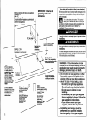
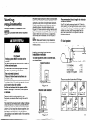
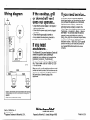
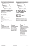
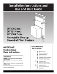
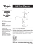
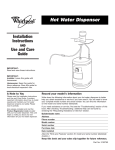
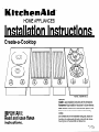
HOME APPLIANCES
Installation Instructions
Create-a-Cooktop
I
D
IMPORTANT:
Read and save these
instructions.
I I
Part No. 3182048 Rev. E
Important:
Installer: Leave Installation Instructions with the homeowner.
Homeowner: Keep Installation Instructions for future reference.
Save Installation Instructions for local electrical inspector’s use.
Write down the model and serial numbers before installing
cooktop.
Both numbers are on the model/serial rating plate, located on
the bottom of cooktops and grills and on the right side, above
the wiring box on the downdraft vent blower box.
Minimum cabinet width above one appliance:
cooktops
- 12”
Grill - 14”
Downdraft vent - 6”
For each additional appliance combined with
the first appliance, add the minimum cabinet
width for that appliance.
IMPORTANT: Observe
governing codes and
ordinances.
Your safety and the safety of others is very important.
We haveprovided many important safety messagesin this
manualand on your appliance.Always read and obey all
safety messages.
This is the safety alert symbol. This symbol
alerts you to hazardsthat can kill or hurt you
and others. All safety messageswill be precededby the
safetyalert symbol and the word “DANGER”or
“WARNING”.Thesewords mean:
all
You will be killed or seriously injured if you don’t follow
instrtions.
LElectric
- I” min.
Gas - 1’ min to
backsplash
or vertical
’
I
See Note* for
minimum
clearances.
16” min. clearance upper
cabinet to countertop
You can be killed or seriously injured if you don’t follow
instraons.
All safety messageswill identify the hazard,tell you how to
reducethe chanceof injury, and tell you what can happen
if the instructions are not followed.
wall
Electric - 4’ min.
Gas - 3” min. countertop
space to side wall or other
combustible
surface
l Note:
24” min. clearance
when bottom of wood
or metal cabinet is
protected by not less
than l/4” flame
retardant millboard
covered with not less
than No. 26 MSG
sheet steel, 0.015”
stainless steel, 0.024”
aluminum or 0.020”
copper.
30” min. clearance
between the top of the
cooking platform and
the bottom of an
unprotected
wood or
metal cabinet.
-
supply cord between
cooktop and cabinet.
Wall as line opening
5” be Bow countertop
and centered with
cooktop.
Gas supply line
piping and electrical
supply MUST NOT
interfere with
downdraft vent
ductwork.
/
2
0-
Outlet Electric cooktops:
Locate supply junction
box on floor or on wall
at least 9” below
countertop.
Gas cooktops:
12” max. from
right side of
cooktop; 15” max.
from bottom of
countertop.
Do not store or use gasoline or other
flammable vapors and liquids in the
vicinity of this or any other appliance.
- WHAT TO DO IF YOU SMELL GAS
l Do not try to light
any appliance.
l Do not touch
any electrical switch.
l Do not use any phone
in your
building.
l Immediately
call your gas supplier
from a neighbor’s
phone. Follow the
gas supplier’s instructions.
l If you cannot
reach your gas
supplier, call the fire department.
- Installation
and service must be
performed by a qualified installer,
service agency or the gas supplier.
Before vou start...
Proper installation iz your responsibility. Make
sure you have everything necessary for correct
installation. It is the responsibility of the installer
to comply with the installation clearances
specified on the model/serial rating plate. The
model/serial rating plate is located on the bottom
of cooktops and grills and on the right side,
above the wiring box on the downdraft vent
blower box.
Check location where cooktops, grills and
downdraft vents will be installed. The location
should be away from strong draft areas, such as
windows, doors and strong heating vents or fans.
All should be located for convenient use in the
kitchen.
Do Not obstruct the flow of combustion
and
ventilation
air.
ALL OPENINGS IN THE WALL OR FLOOR
WHERE COOKTOPS, GRILLS AND
DOWNDRAFT VENTS ARE TO BE INSTALLED
MUST BE SEALED.
Grounded electrical outlet is required. See
“Electrical requirements,” Page 6.
When installing a downdraft vent, the cabinet
drawer(s) will need to be removed and the
drawer front(s) installed permanently to cabinet.
Proper gas supply connection
must be
available. See “Gas supply requirements,”
Page 19.
30” min. base cabinet is required. If cabinet has
a drawer, a 3-l /2” depth clearance from the
countertop to the top of the drawer (or other
obstruction) in base cabinet is required.
Product dimensions
All cooktops are same size. The distance to the
front edge of the countertop, distance to a side
wall or other combustible surface, location of
electric supply and height to cabinets above
cooktop varies depending whether the cooktop is
gas or electric.
Cabinet construction:
This appliance is
designed for use in a base cabinet with a depth
of 24”. The maximum depth for the overhead
cabinets is 13”. The minimum vertical clearance
between the cooking surface and the overhead
depends on the type of overhead cabinets you
have. (See Note, Page 2.) Overhead cabinets
installed at either side of the appliance must be a
minimum of 18” above the cooking surface. The
minimum distance between the front edge of the
countertop and the front edge of the cooktop is
3/4”. The minimum horizontal distance between
overhead cabinets above appliances is the same
as the width of the installed appliances.
When installing a cooktop under existing cabinets
and the installation does not meet the minimum
cabinet clearances, install a range hood above
the cooktop.
Important: Observe all governing codes and
ordinances.
WARNING: To reduce the risk of fire, electric
shock, or injury to persons, observe the
following:
Installation work and electrical wiring must be
done by qualified person(s) in accordance with
all applicable codes and standards, including
fire-rated construction.
Sufficient air is needed for proper combustion
and exhausting of gases through the flue
(chimney) of fuel burning equipment to prevent
back drafting. Follow the heating equipment
manufacturer’s guideline and safety standards
such as those published by the American
Society for Heating, Refrigeration and Air
Conditioning Engineers (ASHRAE), and the
local code authorities.
When cutting or drilling into wall or ceiling, do
not damage electrical wiring and other hidden
utilities.
Ducted fans must always be vented to the
outdoors.
WARNING: To reduce the risk of fire, use only
metal ductwork.
It is the customer’s
responsibility:
To contact a qualified electrical installer.
To assure that electrical installation
is
adequate and in conformance
with National
Electrical Code, ANSI/NFPA 70 - latest
edition*, and all local codes and ordinances.
Copies of the standards listed above may be obtained from:
* National Fire Protection
Association
Batterymarch
Park
Quincy, Massachusetts
02269
3
Product/cutout
Dimensions
Single Installations
-
Electric and Gas
cooktops
One product
per cutout
Electric Grill
lf-1345/16”
-4
WARNING: To reduce the risk of fire, electric shock and injury to
persons, the downdraft vent system must be installed with either
the KitchenAid Model KPED890T exterior mounted motor unit or
the KitchenAid Model KPID850T interior mounted motor unit.
These units are marked to indicate their suitability
with the
downdraft vent system. Other motor units cannot be substituted.
Downdraft Vent
c5-15116”
-I
Exterior
mounted
motor
Interior
mounted
motor
I ne downdratt vent system can
be installed with either an interior
mounted motor or an exterior
mounted motor. Exterior roofmounted system requires Roof
Mount Kit, Part No. 4173296,
which includes dome cover and
flashing. See your KitchenAid
dealer for this kit. One exterior
power vent motor can be used to
operate two downdraft vent
systems.
Combinations
When installing
cooktops,
grills and downdraft
vents in the same cutout,
use the following
width
dimensions:
1 cook-top and
1 downdraft vent
2 cooktops and
1 downdraft vent
Combination
Cutout Width
2 cooktops
3 cook-tops
4 cooktops
23’ min.
35’ min.
47” min.
16-7/a’ min.
29” min.
3 cooktops and
2 downdraft vents
47’ min.
Combination
4 cooktops and
3 downdraft vents
Cutout Width
All other dimensions
1 cooktop, 1 downdraft
vent and 1 grill
65’ min.
2 cook-tops,
2 downdraft vents and
1 grill
31’ min.
49’ min.
1 grill and
1 downdraft vent
1a-718.
min.
2 grills and
1 downdraft vent
33’ min.
3 grills and
2 downdraft vents
53” min.
I
remain the same for all cutouts:
Cutout depth: 20-l/2”
Cutout to front of countertop:
1-l/2”
Cutout to rear wall: 1"
Cutout to combustible
surface: 4” electric
3"
Special
l
l
l
note for installations
gas
with gas cooktop:
If a single downdraft vent is to be installed next to a gas cooktop, the
downdraft vent must use the interior mounted vent motor only.
If a gas cooktop is to be located between two downdraft vents, an
exterior vent motor and ‘7” adapter kit must be used.
T’ adapter kits (Black 4175456, White 4319251, Almond 4319252) are
available from your KitchenAid dealer.
5
Tools/Parts
Electric Cooktop and Grill
Tools and
materials needed
for installation:
Electrical
requirements
Electric
cooktops
and grills
IB.(
El
COOKTOPS AND GRILLS MUST
BE CONNECTED WITH COPPER
WIRE ONLY.
Wire sizes and connections must
conform to the requirements of the
National Electrical Code, ANSVNFPA
70 - latest edition**, and all local codes and
ordinances. Wire sizes and connections must
conform with the rating of the appliance.
n
pipejoint
,Hl
compound
Failure to do so can result in death, fire,
Downdraft
l
l
l
l
l
l
l
l
vents
Phillips screwdriver
metal snips
wire stripper or utility
duct tape
caulking gun
measurmg tape/ruler
flat-blade screwdriver
or 7/16” nut driver
pencil
power supply cable
saber saw or key
hole saw
l drill
l 118” drill
bit
l pliers
l level
l 1Omm or 3/8”
nut driver or ratchet
l
l
knife
Parts supplied for
installation:
Downdraft
vents
literature
6
1
1
4
2
2
control knob
capacitor bracket
wire nuts
conduit connectors
#8 Phillips-head
screws to attach
capacitor bracket
4 #6 Phillips-head
screws to attach
plenum
If codes permit and a separate ground wire is
used, it is recommended
that a qualified
electrician determine that the ground path is
adequate.
Do Not ground to a gas pipe.
Check with a qualified electrician if you are
not sure the appliance is properly grounded.
Do Not have a fuse in the neutral or ground
circuit.
IMPORTANT:
Save Installation
Instructions
for electrical inspector’s
use.
A.
A three-wire, single phase 240-volt,
60-Hz, AC-only electrical supply is
required on a separate 20-ampere
circuit, fused on both sides of the line.
A time-delay fuse or circuit breaker is
recommended.
The fuse must be sized per local codes in
accordance with the electrical rating of the
appliance specified on the model/serial rating
plate located on the bottom of the cooktop or grill
burner box.
(DI
Each appliance should be connected
directly to the fused disconnect (or
circuit breaker) through flexible,
armored or non-metallic sheathed, copper cable.
The flexible, armored cable extending from the
appliance should be connected directly to the
junction box.
w
El
Locate the junction box to allow as
much slack as possible between the
junction box and the appliance so that
the appliances can be moved if servicing is ever
necessary. Do Not cut the conduit.
.
El
El
.
A U.L.-listed, l/2” conduit connector
must be provided at the junction box.
A wiring diagram is located in the
literature package or on the bottom of
the cooktop and grill.
Copies of the standards listed above may be obtained from:
l * National
Fire Protection
Association
Batterymarch
Park
Quincy, Massachusetts
02269
Electrical
connection
This appliance is manufactured with a frameconnected, green or bare, ground wire.
Connect the appliance cable to the junction box
through the U.L.-listed conduit connector.
Complete electrical connection according to local
codes and ordinances.
(Al
.
Where local codes permit connecting
the frame-ground
conductor to the
neutral (white) junction box wire:
(BI
n
junction
cable from power supply
red wires
I I
Where local codes Do Not permit
connecting
the frame-ground
conductor to the neutral (white)
box wire:
cable from power
junction
supply
box
twist-on
connectors
red
wires
connector
-lack
1 black wires
5-i
Electrical Shock Hazard
Turn power supply off before connecting
wires.
Electrically
ground cooktop.
Failure to follow these instructions
could
result in death, fire, or electrical shock.
cable from
appliance
Grounded
. U.L.-listed
connector
conduit
neutral
Figure 1
1. Disconnect the power supply.
2. Connect the flexible armored cable that
extends from the cooktop to the junction box
using a U.L.-listed conduit connector. Tighten
screws on conduit connector.
3. Connect the green (or bare) appliance cable
wire with the neutral wire in the junction box.
4. Connect the two black wires together; then
connect the two red wires together.
(See Figure 1.)
cable from
appliance
Ungrounded
wires
h/
‘U.L.-listed
connector
conduit
neutral
Figure 2
1. Disconnect the power supply.
2. Connect the flexible armored cable that
extends from the cooktop to the junction box
using a U.L.-listed conduit connector. Tighten
screws on conduit connector.
3. Connect the two black wires together; then
connect the two red wires together.
(See Figure 2.)
4. Connect the green or bare ground wire from
the appliance cable to a grounded wire in the
junction box.
5. Put a twist-on connector on end of white wire.
7
Electric Cooktop and Grill (cont.)
Now start...
With cooktop
and/or
I
If installing more than one appliance in the same
cutout, work with one appliance at a time. Start
with the appliance that will be to the left side of
the cutout. Make all adjustments: then follow
steps to add adjacent appliances.
P-l
.
q1
Remove the shipping materials and tape
from the cooktoo or orill. Remove the
hardware package from the the side of the
carton.
1
15.1
grill in kitchen.
Remove the cooktop or grill from the
cutout and place it upside-down on a
protected surface. Remove the paper backing
from a small section of the foam sealing strip.
Place the strip l/8” from cooktop edge on the
underside of the glass. Continue until foam strip
completely outlines the edge of the cooktop or
grill. If you are installing more than one appliance
in the same cutout, you do not need to place
foam strip on the side that will be adjacent to
another appliance.
Do Not use additional sealant around outer edge
of cooktop
or grill(s).
Insert the cooktop or grill into the cutout
and align it with the pencil line. Check
that cooktop orgrill is parallel to the front edge of
the countertop. Lift the entire cooktop or grill to
make adjustments so the foam sealing strip can
seal properly.
If you are installing only one appliance in
cutout, go to Step 7.
If you are installing additional electric
cooktops or grills in the same cutout:
Complete Steps 1, 3, 4, 5, and 6 for each
additional appliance.
If you are installing a gas cook-top or a
downdraft vent as an additional appliance,
read and follow specific installation instructions
for those products.
support
brace
/
To avoid scratching
countertop,
lift entire
cooktop or grill up from cutout when
repositioning
cooktop or grill in countertop
opening.
q
2
Insert the cooktop or grill into countertop
opening. Check that the front of the cooktop or
grill is parallel to the front edge of the countertop.
Check that all required clearances are met. Use
a pencil to mark a line along the rear of the
cooktop or grill on the countertop.
8
04 .
Attach mounting brackets to each side
of the burner box with the 5/l 6” screws.
Do Not tighten the screws. Turn the mounting
brackets so each is under the burner box. If you
are installing additional appliances in the same
cutout, attach one mounting bracket to the right
side of each additional appliance.
06
&rfGws
.
Attach support brace to side of the
cooktop or grill that will be adjacent to
another appliance. Insert additional cooktop or
grill into the cutout and align with the pencil line
used for first cooktop or grill. Check that cooktop
or grill is parallel to the front edge of the
countertop. Lift the entire cooktop or grill to make
adjustments so the foam sealing strip can seal
properly.
Repeat for additional cooktops or grills.
1 8.1
Make the efectrjcal connection. (See
“Electrical requirements” and “Electrical
connection” sections, Pages 6 and 7, for details.)
I9.1
(101
Turn on the power supply.
.
Push in and turn each control knob
to the “HI” position. Check the
operation of the cooktop and or grill heating
elements and indicator lights.
correspond
to steps.
Do Not overtighten
screws.
glass cooktop
7
El
.
countertop
5/16” clamping
bracket screw
One cooktop or grill in cutout:
Rotate the mounting brackets away from
the burner box. Tighten the mounting brackets to
the burner box. Insert the 2-l/2” clamping screws
into the mounting brackets. Use a screwdriver to
tighten the screws against the underside of the
countertop. Remove the pencil outline from
countertop.
Multiple cooktops and/or grill combinations:
Rotate the left mounting bracket away from the
burner box of the first appliance. Tighten the
mounting bracket to the burner box. Insert the
2-l/2” clamping screw into the mounting bracket.
Use a screwdriver to tighten the screw against
the underside of the countertop.
Rotate right mounting bracket away from the
burner box. Attach other end of mounting bracket
to adjacent appliance with a 5/l 6” screw. Use a
screwdriver to tighten mounting bracket to both
appliances. Repeat for each additional appliance.
Rotate mounting bracket of the appliance that will
be adjacent to the right side of the cutout away
from the burner box. Tighten the mounting
bracket to the burner box. Insert the 2-l/2”
clamping screw into the mounting bracket. Use a
screwdriver to tighten the screw against the
underside of the countertop.
Remove the pencil outline from countertop.
To get the most efficient use from
1 your new cooktop and/or grill, read
your KitchenAid
Use and Care
Guide. Keep Installation
Instructions
’ and Guide close by for easy
reference.
9
Downdraft
Vent
Electrical
requirements
El
WARNING: To reduce the risk of fire,
electric shock and injury to persons, the
downdraft vent system must be installed
with either the KitchenAid
Model
KPED890T exterior mounted motor unit or
the KitchenAid
Model KPID850T interior
mounted motor unit. These units are
marked to indicate their suitability
with the
downdraft vent system. Other motor units
cannot be substituted.
IMPORTANT:
for electrical
Save Installation
inspector’s
use.
Instructions
Electrical Shock Hazard
Electrically
ground cooktop.
Failure to do so can result in death or
electrical shock.
If codes permit and a separate ground wire is
used, it is recommended
that a qualified
electrician determine that the ground path is
adequate.
Do Not ground to a gas pipe.
Check with a qualified electrician
if you are
not sure the appliance is properly grounded.
Do Not have a fuse in the neutral or ground
circuit.
10
A 120-volt, 60-Hz, AC only electrical
supply is required on a separate
’ 15-ampere circuit, fused on both sides
of the line. A time-delay fuse or circuit breaker is
recommended. The fuse must be sized per local
codes in accordance with the electrical rating of
the appliance specified on the model/serial rating
plate located on the right side, above the wiring
box on the downdraft burner box.
THE DOWNDRAFT VENT MUST BE
CONNECTED WITH COPPER WIRE
ICI
Wire sizes and connections must
conform to the requirements of the
National Electrical Code, ANSI/NFPA
70 - latest edition**, and all local codes and
ordinances. Wire sizes and connections must
conform with the rating of the appliance.
1
Each appliance should be connected
directly to the fused disconnect (or
ID.I
circuit breaker) through flexible,
armored or non-metallic sheathed, copper cable
(with ground wire). Allow some slack in the cable
so the downdraft vent can be moved if servicing
is ever necessary.
El
A U.L.-listed, l/2” conduit connector
must be provided at the junction box.
El
A wiring diagram is located in the
literature package or on the inside
cover of the downdraft vent wiring box.
Copies of the standards listed above may be obtained from:
**National Fire Protection Association
Batterymarch
Park
Quincy, Massachusetts
02269
Electrical
connection
1. Cut a 1-l/2” hole in floor or side of cabinet for
power supply wire. The hole cut for electrical
wiring through a wood cabinet should be
sanded until smooth. A grommet (Part No.
302797) must cover the hole cut for electrical
wiring through a metal cabinet.
2. Run flexible armored or nonmetallic sheathed
copper cable (with ground wire) from fused
disconnect circuit breaker or junction box
through the cabinet hole to downdraft vent
location. A U.L.-listed conduit connector must
be provided at each end of the power supply
cable (at the appliance and at the junction
box).
3. See installation steps to connect power supply
to downdraft vent.
Venting
requirements
Ductwork needed for installation
supplied.
Wall cap is provided with interior
motor.
is not
mounted
Flexible metal ductwork is Not recommended.
If it is used, calculate each foot of flexible metal
ductwork as two feet of straight metal ductwork.
Flexible metal elbows count twice as much as
standard elbows. Use metal ductwork only.
Figures 3-7 show common venting methods and
types of materials needed. If the ductwork cutout
location falls over a joist or stud, a supporting
frame must be constructed. Do not cut joist or
stud.
NOTE: Make sure there is proper clearance
within the wall or floor for exhaust duct before
making cutouts.
Recommended
duct length for interior
mounted blower
Use 6” duct with maximum length of 25 feet for
duct system. For best petformance, use no more
than three 90” elbows. To calculate the length of
system you need, add the equivalent feet for
each duct piece used in the system. See the
following example:
6” duct system
90” elbows
1,6fi-
--+I_
II
I
Fire Hazard
system MUST terminate
Venting
to the
outside.
Do Not terminate the ductwork in an attic or
other enclosed space.
Do Not use 4-inch laundry-type
wall caps.
Do Not use plastic-type
ductwork.
Use only metal ductwork.
Failure to follow these instructions
can
result in a fire.
To reduce risk of fire and to properly exhaust
air, be sure to duct air outside.
Do Not vent exhaust air into spaces within
walls or ceilings or into attics, crawl spaces
or garages.
Determine which venting method to use.
Ductwork can extend either through the wall or
roof.
The length of the ductwork and number of elbows
should be kept to a minimum to provide efficient
performance. The size of the ductwork should be
uniform. Do Not install two elbows together. Use
duct tape to seal all joints in the duct system.
Use caulking to seal exterior wall or floor opening
around cap.
Interior mounted vent motor
installation
methods
To install ductwork
see Insert Sheet.
under a concrete
wall cap
slab,
Maximum length
I
Island location
2 - 90 elbows
1 - wall cap
8 feet straight
Length of 6” system
Recommended
standard
=
=
=
=
= 25 ft
loft.
Oft.
8ft.
18 ft.
fittings
Figure 3
Interior
wall location
3-l /4” x 10” to 6”
90” elbow = 5 ft.
PO0elbow =
i ft.
Figure 4
6” to 3-l /4”
x lo” = 1 ft.
45” elbow
= 2.5 ft.
6” to 3-l /4” x lo”
90” elbow = 9 ft.
6” wall cap min.
28 in.2 open = 0 ft.
11
Downdraft
Vent (cont.)
Exterior mounted vent motor
installation
methods
Recommended
duct length for
exterior mounted blower
Roof venting
Use 9” duct with a maximum length of 55 feet for
duct system. For best performance use no more
than five 90” elbows.
To calculate the length’ of the system you need,
add the equivalent feet for each duct piece used
in the system.
See the following example:
To install ductwork under a concrete slab,
see Insert Sheet.
Do not install exterior vent motor in a window
well.
Island location
9” duct system
I
Figure 7
Figure 5
Interior
wall location
One exterior power vent motor can be used to
operate two downdraft vent systems. The motor
can be operated by either downdraft vent control.
A T-vent Adapter Kit, (Black 4175456, White
4319251, Almond 4319252) must be used and is
available from your dealer or authorized parts
distributor. The maximum length of the ductwork
including elbows for a T-vented system is 45
feet. The T-vent is the equivalent of 10 feet.
Instructions for installing a T-vented system are
included with the kit.
Maximum length
2 - 90 elbows
1 - wall cap
10 feet straight
Length of 9” system
Recommended
standard
3-l /4” x 14” to 9” 3-l 14” x 14” to 9”
= 4.5 ft.
I 90” elbow = 5 ft.
90” elbow = 5 ft.
Figure 6
9” round
9” to 3-l/4”
1 ft.
X 14” =
= 55 feet
=lOft.
= 0 ft.
= 10 ft.
= 20 ft.
fittings
9” to 3-l/4” x 14”
I 90” elbow = 9 ft.
450 e,bow = 2.5 ft.
Now start .
n
n
n
El
1
Place cardboard or other form of
protection on top of a flat surface where
you can easily assemble the downdraft
vent system. Remove downdraft blower box and
motor section from cartons. Remove any
shipping materials, tape and protective film from
downdraft blower box and motor. Remove parts
package from inside blower box opening.
Remove capacitor from motor.
cl
2
.
g
Excessive Weight Hazard
Use two or more people to move and install
downdraft vent.
Failure to follow this instruction
can result
in back or other injury.
08
Determine which direction (right, left or
down) the ductwork will run from the
blower duct when installed in the
cabinet. Place the motor on the blower box so
that the duct opening is in the position you need
to complete the ductwork. Do Not tighten screws.
n
Measure location of
blower motor duct.
6” blower motor
exhaust duct \
I
I4
*
1 ITT
Determine which direction (right or left)
the blower box with motor attached will
need to be installed.
leg-mounting
hole
/
-
I
Transfer measurements
and cut duct
opening in cabinet floor or wall
dependmg on your installation.
Cut opening
/
\
(two on each side)
1 if-f
\’
that attach the
wiring box to the blower box. Place screws and
wiring box in a safe place.
191
.
cover to blower box
‘V
so that the control end
will be at the front of the cutout.
Use a Phillips
screwdriver to
5 n remove the
El
screws that
attach the legs to the
blower box. Place the
slotted area of legs over
the area where the screw openings are located.
Replace the screws but Do Not tighten screws.
Determine center of blower motor duct in
relation to one leg-mounting hole. Use
this measurement to locate center of blower
motor duct cutout. Cut 6-inch duct opening.
13
Downdraft
Vent /cont.)
If downdraft vent is installed next
to another appliance in the same
cutout, go to Step 11.
If downdraft vent will be installed in a
separate cutout (no other appliances in same
cutout), remove the motor from the blower box.
Carefully insert the blower box into the
countertop cutout.
Lift motor up and place on blower box. Connect
the motor and power supply wiring as described
in Steps 11 - 16 and 18 - 21.
green .
ground
wire
\Y
Thread wires from the motor conduit through
conduit connector and through the opening of the
wiring box. Tighten the conduit connector screws.
0
0
-I
T
Power supply
wiring is not
I . I1
I
I
1
I
I
I
114.I
m
provided.
brown capacitor
us
V- \
ower
supply cable
motor cable
Disconnect power supply. Thread the power
supply cable through the conduit connector.
Tighten the screws on the conduit connector.
Connect the two, white wires together with a
twist-on wire connector.
Connect the black wire from the power supply
cable to the black wire of the control with a twiston wire connector.
Connect the three, green ground wires together
with a twist-on wire connector.
0
Use all four nuts to attach the motor to the blower
box. Use a 10 mm or 3/8” ratchet to tighten the nut
located inside the duct opening. Be sure to tighten
this nut or vibration may occur, causing noise
during operation.
cable
Connect the red wire from the motor to the red
wire from the control with a twist-on wire
connector.
14
capacitor. Thread the two, brown
wires with spade terminals through the rubber
cap of the capacitor. Attach one wire to one of
the inside capacitor terminals. Then attach the
other brown wire to the other capacitor terminal.
Replace the rubber cap over the top of the
capacitor. Put the capacitor into the mounting
bracket on the lower section of the wiring box.
Position the
downdraft vent cover
so that it is aligned with
light pencil marks made
on the countertop in Step
6. Use screws to attach legs
to cabinet floor. Check that blower
box is vertical. (Adjust legs until
blower box is vertical.) Tighten screws that attach
the legs to the blower box.
the front of the
blower box under the
control using the four
screws removed in Step 3.
If the vent is installed in
the cutout, it may have to
be lifted out of the
countertop opening a few inches to attach wiring
box.
Connect 6” ductwork to blower duct.
Position ductwork to avoid wall studs
and floor joists. Complete all
ductwork. Use duct tape to seal all joints.
Ductwork must end with a wall or roof cap.
Insert grease filter and place grille in
position. If downdraft vent is
installed between two appliances,
attach a support brace to each side of the
downdraft vent cover.
Repeat Steps 1-21 for each downdraft
vent.
b-l
Turn power supply on. Place the
control knob securely onto the stem.
Check the operation of the blower
and speed control. If one does not operate,
disconnect power source and check that wire
connections have been made correctly.
,
Excessive Weight Hazard
Use two or more people to move and install
downdraft vent.
Failure to follow this instruction
can result
in back or other injury.
49.
I
Numbers
correspond
to steps.
Insert downdraft
blower box and
motor into countertop cutout. Two people are
recommended to support the weight of the
downdraft vent during lifting.
15
Downdraft
Exterior roof-mounted
system
Mount Kit, Part No. 4173296.
Vent (cont.)
requires
Roof
11.1
Place cardboard or other form of
protection on top of a flat surface where
you can easily assemble the downdraft vent
system. Remove downdraft blower box and
motor sections from cartons. Remove any
shipping materials, tape and protective film from
downdraft blower box and motor. Remove parts
package from inside blower box opening.
blower box. Place screws and wiri;g
safe place.
cl3
box in a
I
Use four screws to attach vent cover to
blower box so that the control end will
be at the front of the cutout.
16
.
)41
.
Place the adapter plate, which includes a
back-draft damper, and 9” round take-off
on the blower box. Use all four nuts to attach the
adapter to the blower box.
05
Use a Phillips screwdriver to remove the screws
that attach the legs to the blower box. Place the
slotted area of legs over the area where the
screw openings are located. Replace the screws
but Do Not tighten screws.
Excessive Weight Hazard
Use two or more people to move and install
downdraft vent.
Failure to follow this instruction
can result
in back or other injury.
Inset-l downdraft
vent into
countertop cutout.
112
.
Position the
downdraft vent
cover so that it is
aligned with light pencil
marks made on the countertop
in Step 6. Use screws to attach
legs to cabinet floor. Check that
blower box is vertical. (Adjust
legs until blower box is vertical.)
Tighten screws that attach the legs to the blower
box.
Determine the location where the
exterior blower assembly will be
installed. Cut a 10” diameter hole in
the wall or roof.
Connect 9” ductwork to blower duct.
Position ductwork to avoid wall
studs and floor joists. Complete all ductwork. Use
duct tape to seal all joints. Vertical ductwork for
wall-mounted installations should pitch down
slightly toward the vent to allow moisture to run
outside.
Thread the motor
cable through
screws.
I
WI
I
Remove the dome top. Loosen
conduit connector screws. Thread
the motor cable through the conduit
connector. Tighten the screws on the conduit
connector. Connect the white and black wires of
the motor wiring cable to the white and black
leads of the motor with twist-on wire connectors.
Connect the green, ground wire of the motor
wiring cable to the ground connection screw.
Place wires under clip to prevent hitting the motor
cooling blade.
For wall-mounted installations, replace the dome
top to cover the motor and connections. Roof
installations require a roof cap to be used in
place of the dome.
n
11
Wiring between motor and blower
box is not provided.
Install exterior blower with the supply
.
El
connector at the top.
Wall Installations
. Use caulking compound between mounting flange
and wall.
Roof Installations
. Follow standard roofing procedures.
. The flashing sheet should be entered over the
opening of the roof.
. The lower edge of the flashing should lie on top of
the shingles and the upper edge should be
underneath the shingles.
Seal the assembly between the roof, fan and
flashing with the roofing mastic to prevent leaks.
green
ground
wire
red
l2
black wire
/
14
Run motor wiring through the duct
access area to the wiring box on the
blower box.
1
If two downdraft vents will be operated from
one external vent motor, only one switch can
be wired to operate both downdraft vents. Do
Not wire both switches. Determine which switch
will be most convenient to use.
I
/
black
wire
2iy
”
reen
round
wires
cable
Connect the red wire from the motor
cable to the red wire from the control
with a twist-on wire connector.
l
17
Downdraft
Vent (cont.)
Power supply
wiring is not
provided.
green
ground
15.16.
‘;r
!/I\
Numbers
correspond
steps.
to
lfT3ire
Aconnector
Thread the power supply cable through the
conduit connector. Tighten the screws on the
conduit connector.
Disconnect power supply.
Connect the two white wires together with twiston wire connector.
Connect the black wire from the power supply
cable to the black wire of the control with a twiston wire connector.
Connect the three green ground wires together
with a twist-on on wire connector.
If downdraft vent is being installed in a separate
cutout, it may have to be lifted out of the opening
ll~.l
Atheiring
box to the
front of the blower box under
the control using the four
screws removed in Step 2.
18
a few inches to do this.
Turn power supply on. Place control
knob securely over stem. Check the
operation of the blower and speed
control. If one does not operate, disconnect
power source and check that wire connections
have been made correctly.
Insert grease filter and place grille in
position.
If downdraft vent is installed between two
appliances, attach a support brace to each side
of the downdraft vent cover.
To get the most efficient use from your
new downdraft vent, read the Use and
Care information
section on the back
coveE Keep Installation
Instructions
and Use and Care Guide close by for
easy reference.
Sealed Gas Cooktop
Gas supply
requirements
shutoff
(BI
Input ratings shown on the model/serial
rating plate are for elevations up to
2,000 feet. For elevations above 2,000
feet ratings should be reduced at a rate of 4% for
each 1,000 feet above sea level.
valve
.
Copies of the standards listed above may be obtained from:
American Gas Association
1515 Wilson Boulevard
Arlington, Virginia 22209
l
Explosion
Hazard
Use a new AGA approved gas supply line.
Install a shut-off valve.
Securely tighten all gas connections.
If connected to LP, have a qualified person
make sure gas pressure does not exceed
water column rating specified in LP
conversion
kit. Examples of a qualified
person include licensed heating personnel,
authorized gas company personnel, and
authorized service personnel.
Failure to do so can result in death,
explosion,
or fire.
Observe all governing codes and
ordinances.
Important: Cooktop must be
connected to a regulated gas supply.
This installation must conform with
.
local codes and ordinances. In the
El
absence of local codes, installation
must conform with American National Standard,
National Fuel Gas Code ANSI 2223.1 - latest
edition.*
El
This cooktop is manufactured for use
with NATURAL gas and it is designcertified by A.G.A.
L.P. gas conversion
This cooktop can be converted for use with L.P.
gas. However, no attempt shall be made to
convert the appliance from the gas specified on
the rating plate for use with a different gas
without consulting the serving gas supplier.
Conversion must be done by a qualified service
technician. Conversion Kit No. 4173627 is
available from your KitchenAid dealer or
authorized parts distributor.
ID.I
Provide a gas supply line of 3/4” rigid
pipe to the cooktop location. A
smaller size pipe on long runs may
result in insufficient gas supply. Pipe-joint
compounds made for use with NATURAL and
L.P. gas must be used.
El
If local codes and ordinances permit,
n
A.G.A.-design-certified,
new flexible
metal tubing is recommended for
connecting cooktop to the gas supply line. Do
Not kink or damage the flexible tubing when
moving the cooktop. A l/2” male pipe thread is
needed for connection to pressure regulator
female pipe threads.
an approved shutoff valve. This valve
should be located in the same room as
the cooktop and should be in a location that
allows ease of opening and closing. Do Not block
access to shutoff valve. The valve is for turning
on or shutting off gas to the appliance.
El
If rigid pipe is
used as a gas
supply line, a co
El
pipe fittings must be used to obtain an in-line
connection to the cooktop. All strains
must be removed from the supply and fuel lines
so cooktop will be level and in line.
.
The regulator must be checked at a
minimum 1” water column above the
IHI
set pressure. The inlet pressure to the
regulator should be as follows for operation and
checking the regulator setting:
NATURAL GAS:
Set pressure 4 inches
Maximum pressure 14 inches
n
L!-l
n
Line Pressure Testing:
Testing above l/2 psi (gauge)
The cooktop and its individual shutoff valve must
be disconnected from the gas supply piping
system during any pressure testing of that
pressures greater than l/2 psig (3.5 kPa).
Testing at l/2 psi (gauge) or lower
The cooktop must be isolated from the gas
supply piping system by closing its individual
manual shutoff valve during any pressure testing
of the gas supply piping system at test pressures
equal to or less than l/2 psig (3.5 kPa).
19
Sealed Gas Cooktop (cont.)
Electrical
requirements
Electronic ignition systems operate within wide
voltage limits, but proper grounding and polarity
is necessary. In addition to checking that the
outlet provides 120-volt power and is correctly
grounded, the outlet must be checked by a
qualified electrician to see if it is wired with
correct polarity.
A wiring diagram is provided on the bottom of the
cooktop box and in the literature package.
Recommended
Electrical Shock Hazard
Plug into a grounded 3-prong outlet.
Do not remove ground prong.
Do not use an adapter.
Failure to follow these instructions
can
result in death, fire, or electrical shock.
If codes permit and a separate ground wire is
used, it is recommended
that a qualified
electrician determine that the ground path is
adequate.
Do Not ground to a gas pipe.
Check with a qualified electrician
if you are
not sure the appliance is properly grounded.
Do Not have a fuse in the neutral or ground
circuit.
See back page for wiring
and/or
grill in kitchen.
If installing more than one appliance in the same
cutout, work with one appliance at a time. Start
with the appliance that will be to the left side of
the cutout. Make all adjustments; then follow
steps to add adjacent appliances.
method
For your personal safety, this appliance must be
grounded. This appliance is equipped with a
power supply cord having a 3-prong ground plug.
To minimize possible shock hazard, the cord
must be plugged into a mating 3-prong groundtype outlet, grounded in accordance with National
Electrical Code, ANSVNFPA 70 - latest edition
and all local codes and ordinances. See Figure 8.
If a mating outlet is not available, it is the
personal responsibility and obligation of the
customer to have a properly grounded 3-prong
outlet installed by a qualified electrician.
Remove the shipping materials and tape
from the cooktop. Remove the hardware
package from the side of the carton.
3-prong groundtype outlet
diagram.
A 120-volt, 60-Hz, AC only, 15-ampere, fused
electrical supply is required. Time-delay fuse or
circuit breaker is recommended. It is
recommended that a separate circuit serving only
this appliance be provided.
20
ground
Now start...
With cooktop
nd
9
Figure 8
Remove cooktop burner grates and
caps package from shipping box.
Remove pressure regulator and hardware
package from side of carton.
To avoid scratching
countertop,
lift entire
cooktop up from cutout when repositioning
cooktop into countertop
opening.
If you are installing additional appliances in the
same cutout, attach one mounting bracket to the
right side of each additional appliance.
Do Not over-tighten
screws.
glass cooktop
countertop
\
Insert the cooktop into the cutout and
align it with the pencil line. Check that
cooktop is parallel to the front edge of the
countertop. Lift the entire cooktop to make
adjustments so the foam sealing strip can seal
properly.
If you are installing only one appliance in
cutout, go to Step 8.
If you are installing additional gas cooktops
in the same cutout, complete Steps 1, 2, 4, 5, 6
and 7 for each additional appliance.
If you are installing an electric cooktop or grill
or a downdraft vent as an additional
appliance, read and follow specific installation
instructions for those products.
13.)
I
I
Insert the cooktop into the countertop opening.
Check that the front of the cooktop is parallel to
the front edge of the countertop. Check that all
required clearances are met. Use a pencil to
mark a line along the rear of the cooktop on the
countertop.
u4
Remove the
cook-top from the
cutout and place it
upside down on a
protected surface.
Remove the paper backing
from a small section of the
foam sealing strip. Place the strip l/8” from
cooktop edge on the underside of the glass.
Continue until foam strip completely outlines the
edge of the cooktop.
If you are installing more than one appliance in
the same cutout, you do not need to place a
foam strip on the side that will be adjacent to
another appliance.
Do Not use additional sealant around outer edge
of cooktop(
.
E-l
Attach mounting
brackets to each
side of the burner
box with the 5/l 6” screws.
Do Not tighten the
screws. Turn the
mounting brackets so
each is under the burner box.
.
0
I
support
brace
I
I-
I
I
/
/
2-1R”
clamping
screw
1
1
5M6” clamping
bracket screw
181
.
I
One cook-top in cutout: Rotate the
mounting brackets away from the burner
box. Do Not overtighten screws. Tighten the
mounting brackets to the burner box. Insert the
2-l/2” clamping screws into the mounting
brackets. Use a screwdriver to tighten the
screws against the underside of the countertop.
Remove the pencil outline from countertop.
screws
1 .
Attach support brace to side of the
cooktop that will be adjacent to another
appliance. Insert additional cook-top into the
cutout and align with the pencil line used for first
cooktop. Check that cooktop is parallel to the
front edge of the countertop. Lift the entire
cooktop to make adjustments so the foam
sealing strip can seal properly.
Repeat for additional cooktops or grills.
I
21
Sealed Gas Cooktop (cont.)
Multiple
cooktops
and/or grill combinations:
Rotate the left mounting bracket away from the
burner box of the first appliance. Tighten the
mounting bracket to the burner box. Insert the
2-l/2” clamping screw into the mounting bracket.
Use a screwdriver to tighten the screw against
the underside of the countertop.
Rotate right mounting bracket away from the
burner box. Attach other end of mounting bracket
to adjacent appliance with a 5/l 6” screw. Use a
screwdriver to tighten mounting bracket to both
appliances. Repeat for each additional appliance.
Rotate mounting bracket of the appliance that will
be adjacent to the right side of the cutout away
from the burner box. Tighten the mounting
bracket to the burner box. Insert the 2-l/2”
clamping screw into the mounting bracket. Use a
screwdriver to tighten the screw against the
underside of the countertop.
Remove the pencil outline from countertop.
Numbers
correspond
steps.
to
Install the pressure regulator with the
arrow on the regulator pointing up
toward unit and in a position where you can
reach the access cap.
flexible
3/8” nipple
T
\IL!
c1
manual shutoff
connector
310” adapter
3/W nipple
La
7@
310” adapter
pressure
regulator
valve
I
I
Use pipe-joint compound made for
use with NATURAL and L.P. gas to
seal all gas connections. If flexible connectors
are used, be certain connectors are not kinked.
All connections
must
be wrench-tightened.
1101
,
Assemble the flexible connector from
the gas supply pipe to the pressure
regulator in order: Manual shutoff valve, 318”
nipple, 3/8” adapter, flexible connector, 3/8”
adapter, and 3/8” nipple.
22
Open the shutoff valve in the gas supply line.
Wait a few minutes for gas to move through the
gas line.
I131
n
Use a brush and liquid detergent to
test all gas connections for leaks.
Bubbles around connections will indicate a leak.
If a leak appears, shut off gas valve controls and
adjust connections. Then check connections
again. NEVER TEST FOR GAS LEAKS WITH A
MATCH OR OTHER FLAME. Clean all detergent
solution from cook-top.
.
Electronic Ignition System initial lighting
Cooktop burners use electronic ignitors in place
of standing pilots. When the cooktop control knob
is turned to the “HI” position, the system creates
a spark to light the burner. This sparking
continues until the burner ignites.
Plug the power supply cord
into-the grounded outlet.
I
I
t
I
115.1
Place burner grates over
burners and caps. Install
control knobs on valve
stems.
(161
OFF
H Check the
operation of
~ofil
the cooktop burners.
Push in and turn each
2
6
control knob to “HI”
position. The flame
should light within 4
5
3
seconds.
\I!i
If the burners do not
4
light properly, turn the
control knob to the “OFF” position. Check that
the burner cap is plugged in and that the circuit
breaker or fuse has not blown. Check that the
shutoff valve is in the “ON” position. Check
operation again. If burner does not light at this
point, contact your KitchenAid dealer for
assistance.
I
1
1181
. Push in and turn each control knob
to the “LO” (or simmer) setting. The
“LO” setting of each burner has been factory set
to the lowest setting available to provide reliable
reignition of the burner. If it does not stay lit on
the “LO” setting, contact your KitchenAid dealer
for assistance.
To get the most efficient use from
your new cooktop, read your
KitchenAid
Use and Care Guide.
Keep Installation
Instructions
and
Guide close to cooktop for easy
reference.
1171
.
Check each cooktop burner
for proper flame. The small
inner cone should have a very distinct
blue flame approximately l/2” long. The
outer cone is not as distinct as the inner
cone.
23
Wiring diagram
If the cooktop, grill
or downdraft vent
does not operate...
(WNHT,
BkK)
(GEN)
II
L-h
l
l
l
Check that the circuit breaker is not tripped or
the house fuse blown.
Check that the power supply cord is plugged
into outlet.
Check that the gas supply is turned on.
A more detailed troubleshooting checklist is
provided in the Use and Care Guide.
If you need
assistance...
I
I I I
/
(RED)
I\
wHT)
(BLK)
-
In the event that your KitchenAid appliance
should need service, call the dealer from whom
you purchased the appliance or a KitchenAidauthorized service company. A KitchenAidauthorized service company is listed in the
Yellow Pages of your telephone directory under
“Appliances - Household - Major - Service
and Repair.” You can also obtain the service
company’s name and telephone number by
dialing, free, within the continental United States,
the KitchenAid Consumer Assistance Center
telephone number, l-(800) 422-l 230. A special
operator will tell you the name and number of
your nearest KitchenAid-authorized
service
company.
The KitchenAid Consumer Assistance Center will
answer any questions about operating or
maintaining your appliances not covered in the
Installation Instructions. The KitchenAid
Consumer Assistance Center is open 24 hours a
day, 7 days a week. Just dial l-(800) 422-1230
- the call is free.
When you call, you will need the appliance model
number and serial number. Both numbers can be
found on the model/serial rating plate located on
the burner box or blower housing of the
appliances.
I
,
(RED
(BLK)
If you need service...
0
-
n
GAS VALVE
REAR
GAS VALVE
FRONT
Caution: Label all wires prior to disconnection when servicing
controls. Wiring errors can cause improper and dangerous
operation.
Verify proper operation after servicing.
Part No. 3182048 Rev. E
0 1998 KitchenAid
@ Registered
Trademark
HOME APPLIANCES
of KitchenAid,
U.S.A.
Prepared by KitchenAid, St. Joseph, Michigan 49085
Printed in U.S.A.