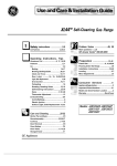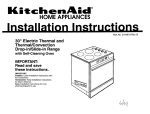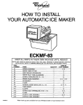
1
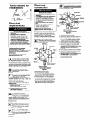
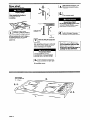
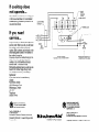
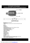
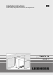
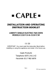
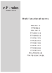
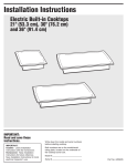
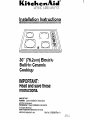
30” (76.2cm) Electric
Built-in Ceramic
Cooktop
IMPORTANT:
Read and save these
instructions.
IMPORTANT:
Installer:
Leave Installation Instructions
with the homeowner.
Homeowner:
Keep Installation Instructions
for future reference.
Save Installation Instructions for local
electrical inspector’s use.
Part No. 3188086 Rev. A
Product dimensions
Before you start...
/+-3V
(762cm)
width
Proper installation is your responsibility.
Make sure you have everything for correct
installation. It is the responsibility of the
installer to comply with the installation
clearances specified on the serial/rating
plate. The serial/rating plate is found on the
bottom of the cooktop.
-W
Cooktop installed over oven installation:
Cooktop models KECC500W, KECC500B,
YKECC500B and YKECC500W can be
installed over oven models KEBNl OOY,
KEBNlO7B and RB262PXA.
height
Check location where cooktop will be
installed. The location should be away from
strong draft areas, such as windows, doors
and strong heating vents or fans. The
cooktop should be located for convenient
use in the kitchen.
Important:
Observe all governing codes and
ordinances.
Failure to meet governing codes and
ordinances could lead to fire or electrical
shock.
Cabinet dimensions
30” (76.2cm) min. base cabinet is required.
If cabinet has a drawer, a 3” (75cm) depth
clearance from the countertop to the top of
the drawer (or other obstruction) in the base
cabinet is required.
Countertop opening dimensions
that are
shown must be used. Given dimensions are
minimum clearances and provide required
0” (Ocm) clearance.
New installations
-follow
dimensions given.
h-width
f
30” (76.2cm) min. cabinet
above cooktop
For minimum
clearances,
see Note.*
16” (45.7cm)
minimum
Replacement installations
- Be sure that
front edge of cooktop is at least l-1/2”
(3.8cm) back from front edge of countertop.
A built-under oven may be installed under
this cooktop if oven is approved for this type
of installation. Check for approval label
located on top of oven. If label is not
located, contact dealer to confirm that oven
is approved. Refer to oven manufacturers
Installation Instructions for approval and
proper cutout dimensions.
4,
13Lk+
max. upper
cabinet
I
min.
countertop.
When installing cooktop over a builtunder oven, Do Not fasten cooktop to
countertop with clamps. Cooktop then will
be easy to remove if servicing is ever
necessary.
ALL OPENINGS IN THE WALL OR FLOOR
WHERE THE COOKTOP IS TO BE
INSTALLED MUST BE SEALED.
(30cm) or
more above
the floor
line.
25” (63.5cm)
countertop
depth
24” (61cm)
lower cabmet
depth
‘/
/
’
Note: 24” (61cm) min.
clearance rf bottom of
wood or metal cabinet is
protected by not less than
l/4” (O&m) flame
retardant millboard
covered with not less than
No. 28 MSG sheet steel,
0.015” (0.04cm) stainless
steel, or 0.024”(0.06cm)
aluminum or 0.020”
(OJXcm) copper.
30” (76.2cm) min.
clearance between top of
cooking platform and
bottom of unprotected
wood or metal cabinet.
Electrical
Shock Hazard
It is the customer’s
responsibility:
To contact a qualified electrical
installer.
l To assure
that the electrical
installation
is adequate and in
conformance
with National Electrical
Code, ANSVNFPA 70 - latest
edition**, or Canadian Electrical
Code, C22.1 - 1982 and C22.2 No.
01982 (or latest edition)*‘* and all
local codes and ordinances.
l
Failure to do so could result in
electrical shock or other personal
injury.
Personal Injury Hazard
Cabinet storage above the cooking
surface should be avoided. If cabinets
are already installed, reduce the
hazard of reaching over a heated
cooking surface by installing a range
hood.
Cutout dimensions
The range hood should extend a
minimum of 5 inches out from the
bottom of the cabinets.
Reaching over a heated cooking
surface could result in a serious
burn.
Copies of the standards listed may be
obtained from:
-Minimum
distance
to nearest left side
and rear combustible
surface above countertop
Panel A
**National Fire Protection
Batterymarch
Park
Quincy, Massachusetts
Association
02269
***Canadian Standard Association
178 Rexdale Boulevard
Rexdale, (Toronto ), Ontario M9W 1 R3
Tools needed for
installation:
Electrical
connection
Where local codes Do Not permit
connecting
the frame-grounding
conductor to the neutral (white)
junction box wire:
cable from power
Electrical Shock Hazard
Electrical ground is required on this
appliance.
l This
appliance must be connected to
a grounded, permanent wiring
system or a grounding connector
should be connected to the
grounding terminal or wire lead on
the appliance.
l Disconnect
power to the junction
box.
l Do Not connect
to the electrical
supply until appliance is
permanently grounded.
Failure to do so could result in
electrical shock, serious injury, or
death.
supply
l
pencil
Electrical
requirements
Electrical
l
l
l
l
Shock Hazard
Electrical ground is required on this
appliance.
Do Not ground to a gas pipe.
Do Not have a fuse in the neutral or
grounding circuit. A fuse in the
neutral or grounding circuit could
result in an electrical shock.
Check with a qualified electrician
if
you are in doubt as to whether the
appliance is properly grounded.
Failure to follow these in instructions
could result in serious injury or death.
This appliance is manufactured with a frame
connected, green or bare grounding wire.
Connect the appliance cable to the junction
box through the U.L.-listed conduit
connector. Complete electrical connection
according to local codes and ordinances.
Where local codes permit
connecting
the frame-grounding
conductor to the neutral (white)
junction box wire:
cable from
power supply
If codes permit and a separate
grounding wire is used, it is
recommended
that a qualified electrician
determine that the grounding
path is
adequate.
IMPORTANT:
Save Installation
Instructions
for
electrical inspector’s
use.
A
cl
A three-wire or four-wire, single
phase, 240-volt, 60-Hz, AC-only
n
electrical supply is required on a
separate, 40-ampere circuit, fused
on both sides of the line. A time-delay fuse
or circuit breaker is recommended. The fuse
size must not exceed the circuit rating of the
appliance specified on the serial/rating plate
located on the bottom of the cooktop.
b-l
I
n
I
THE COOKTOP MUST BE
CONNECTED WITH COPPER
WIRE ONLY.
0C
Wire sizes and connections must
conform to the requirements of the
. National Electrical Code
ANSVNFPA - latest edition**, or
Canadian Electrical Code, C22.1- 1982, and
C22.2 No. 01982 (or latest edition)*** and
all local codes and ordinances.
Copies of the standards listed may be
obtained from:
**National Fire Protection
Batterymarch
Park
Quincy, Massachusetts
l
Association
02269
** Canadian Standard Association
178 Rexdale Boulevard
Rexdale (Toronto), Ontario M9W 1 R3
qD
The appliance should be
connected directly to the fused
. disconnect or circuit breaker box
through flexible, armored or nonmetallic sheathed, copper cable. The
flexible, armored cable extending from the
appliance should be connected directly to
the junction box.
qE
Locate the junction box to allow as
much slack as possible between
. junction box and the cooktop so
that the cooktop can be moved if
servicing is ever necessary.
A U.L.- or C.S.A.-listed conduit
connector must be provided at
each end of the power supply cable
(at the appliance and at the
junction box).
Panel B
U.i.- or C&A.- listed
conduit connector
cable from cooktop
Grounded neutral
Figure 1
1. Disconnect power supply.
2. Connect the flexible armored cable from
the cooktop to the junction box using a
U.L.- or C.S.A.-listed conduit connector.
Tighten screws on conduit connector.
3. Connect the green (or bare) appliance
cable wire with the neutral (white) wire in
the junction box using twist-on connector.
4. Connect the two black wires together;
then connect the two red wires together
with twist-on connector. (See Figure 1.)
cable from cooktop
Ungrounded neutral
Figure 2
1. Disconnect power supply.
2. Connect the flexible armored cable from
the cooktop to the junction box using a
U.L.- or C.S.A.-listed conduit connector.
Tighten screws on conduit connector.
3. Connect the two black wires together;
then connect the two red wires together
using twist-on connector. (See Figure 2.)
4. Connect the green or bare grounding
wire from the appliance cable to the
grounded wire in the junction box or other
grounded connector using twist-on
connector.
5. Put a twist-on connector on end of white
wire.
6. Contact a qualified electrician to assure
that grounding path is adequate.
7. Do Not ground to a gas supply pipe or
hot water pipe. Do Not connect to
electrical supply until appliance is
permanently grounded.
Make electrical connection. (See
“Electrical requirements” and
“Electrical connection” sections,
Panel B.)
Now start...
With
cooktop
in kitchen.
Property Damage
Lift entire cooktop up from cutout
when repositioning
cook-top in
countertop
opening.
Failure to do so could scratch the
countertop.
clamp
75
’
Turn on power supply.
Personal Injury Hazard
Do Not touch cooktop surface. Areas
near elements may be hot.
Touching a heated cooking surface
could result in a serious burn.
slot
#
Insert the cook-top into the
countertop. Center the cooktop in
the cutout. Check that the front of
the cook-top is parallel to the front
edge of the countertop. Check that all
required clearances are met. If cook-top is
not properly positioned, lift the entire
cooktop out of opening to make
adjustments.
screw and clam
f
clamp tab
burner
box
1
I
121
.
Insert one clamp tab through each
slot located on sides of the burner
box.
Note: If installing cooktop over a built-under
oven, Do Not fasten cook-top to countertop
with clamps. Cooktop will then be easy to
remove if servicing is ever required.
Do Not over-tighten screws
Overtightening
screws could cause
personal injury or product damage.
Secure cooktop to countertop by
hand-tightening each screw; then
use a screwdriver to tighten each
screw 1 to l-112 more turns. Do
Not overtighten screws.
Numbers
correspond
Panel C
Push in and turn each control knob
to the “HI” position. Check the
operation of the cooktop elements
and indicator lights.
To get the most efficient use
from your new cooktop, read
your KitchenAid Use and Care
Guide. Keep Installation
Instructions and Guide close to
cooktop for easy reference.
If cooktop does
not operate...
Check that the circuit breaker is not tripped
or the house fuse blown. A more detailed
troubleshooting checklist is provided in the
Use and Care Guide.
F3
F2
If youI need
service...
Call your dealer or a KitchenAid-authorized
service outlet. When you call, you will need
the cooktop model number and serial
number. Both numbers can be found on the
serial/rating plate located on the bottom of
the cooktop burner box.
All service should be handled locally by the
dealer from whom you purchased the
cooktop or by a KitchenAid-authorized
service outlet. The name of local
KitchenAid-authorized
service outlet can be
found in the Yellow Pages of any metro
area telephone directory under “Major
Appliances.”
If your local service is unsatisfactory,
contact:
KitchenAid Canada
1901 Minnesota Court
Mississauga, Ontario
L5N 3A7
Telephone:
(905)821-6400
G&ND
WIRING DlAGRAM
FACE S/DE OF CFICUIT
Prepared by KitchenAid,
Printed in U.S.A.
BREAKER
St. Joseph, Michigan 49085
Kt+chenAid”
GROUND IN ACCORDANCE
WITH
CANADIAN
ELECTRICAL
CODE
AND APPLICABLE
LOCAL CODES.
SHOWN
Imprime
10 % de
50 % de
Imprime
of KitchenAid.
GROUND
1
t
Printed on recycled paper.
10% post consumer waste/
50% recovered materials.
Part No. 3188086 Rev. A
0 1994 KitchenAid
@ KitchenAid. Registered Trademark
..__...
.__..__..__._._.__._-------.----------------..----.----.....-
sur papier recycle.
rebuts apres usage
matieres kcuperees
aux E.-U.
Piece n” 3188086 Rev. A
0 1994 KitchenAid
@ Kitchen Aid Marque deposee de KitchenAid.
Prepare par KitchenAid,
St. Joseph, Michigan 49085