1
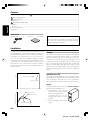
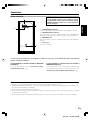
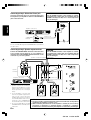
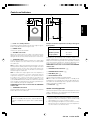
ENGLISH
SW-508
POWERED SUBWOOFER
INSTRUCTION MANUAL
KENWOOD CORPORATION
B61-1229-00 00 MA (Y) KW 0312
SW-508 1229/01/EN
Before applying power
Caution: Read this page carefully to ensure safe operation.
Units are designed for operation as follows.
ENGLISH
Europe and U.K. ................................................ AC 230V only
Australia ............................................................ AC 240V only
Other countries .......................... AC 110-120 / 220-240 V only
switchable*
* AC voltage selection
The AC voltage selector switches on the rear panel are set
to the voltage that prevails in the area to which the unit is
shipped. Before connecting the power cord to your AC
outlet, make sure that the setting positions of these switches
match your line voltage. If not, they must be set to your
voltage in accordance with the following direction.
CAUTION
The power in this equipment will not be completely cut off
from the AC wall outlet when the main switch is turned
OFF.
AC voltage selector switches
Move switch lever to match your line voltage with a
small screwdriver or other pointed tool.
AC220-240
AC110-120
Note: Our warranty does not cover damage caused by
excessive line voltage due to improper setting of the AC
voltage selector switch.
Safety precautions
WARNING : TO PREVENT FIRE OR ELECTRIC SHOCK, DO NOT
EXPOSE THIS APPLIANCE TO RAIN OR MOISTURE.
CAUTION
RISK OF ELECTRIC SHOCK
DO NOT OPEN
CAUTION: TO REDUCE THE RISK OF ELECTRIC SHOCK,
DO NOT REMOVE COVER (OR BACK). NO USER-SERVICEABLE PARTS INSIDE. REFER SERVICING TO QUALIFIED SERVICE PERSONNEL.
THE LIGHTNING FLASH WITH ARROWHEAD SYMBOL, WITHIN AN EQUILATERAL TRIANGLE, IS INTENDED TO ALERT THE USER TO THE PRESENCE OF UNINSULATED “DANGEROUS VOLTAGE” WITHIN
THE PRODUCT’S ENCLOSURE THAT MAY BE OF SUFFICIENT MAGNITUDE TO CONSTITUTE A RISK
OF ELECTRIC SHOCK TO PERSONS.
THE EXCLAMATION POINT WITHIN AN EQUILATERAL TRIANGLE IS INTENDED TO ALERT THE USER
TO THE PRESENCE OF IMPORTANT OPERATING AND MAINTENANCE (SERVICING) INSTRUCTIONS
IN THE LITERATURE ACCOMPANYING THE APPLIANCE.
Introduction
Thank you for selecting our speakers as part of your high-fidelity system. We at KENWOOD are confident that your choice will bring
you years of rich listening pleasure. Please take the time to read through this booklet carefully. It will help you to obtain the peak
performance for which the speakers were designed.
For your records
Record the serial number, found on the back of the unit, in the spaces designated on the warranty card, and in the space provided below.
Refer to these model and serial numbers whenever you call upon your KENWOOD dealer for information or service on this product.
SW-508 Serial number
Unpacking
Unpack the unit carefully and make sure that all accessories are put aside so they will not be lost.
Examine the unit for any possibility of shipping damage. If your unit is damaged or fails to operate, notify your dealer immediately.
If your unit was shipped to you directly, notify the shipping company without delay. Only the consignee (the person or company
receiving the unit) can file a claim against the carrier for shipping damage.
We recommend that you retain the original carton and packing materials for use should you transport or ship the unit in the future.
Keep this manual handy for future reference.
2 EN
SW-508 1229/02-08/EN
IMPORTANT SAFEGUARDS
Caution: Read this page carefully to ensure safe operation.
10. Lightning – For added protection for this appliance during
a lightning storm, or when it is left unattended and unused for
long periods of time, unplug it from the wall outlet and disconnect
the antenna or cable system. This will prevent damage to the
appliance due to lightning and power-line surges.
1. Power sources – The appliance should be connected to a
power supply only of the type described in the instruction
manual or as marked on the appliance. If you are not sure of the
type of power supply to your home, consult your appliance
dealer or local power company. For appliances intended to
operate from battery power, or other sources, refer to the
instruction manual.
11. Abnormal smell – If an abnormal smell or smoke is
detected, immediately turn the power OFF and unplug the
appliance from the wall outlet. Contact your dealer or nearest
service center.
2. Power-cord protection – Power-supply cords should be
routed so that they are not likely to be walked on or pinched by
items placed upon or against them, pay particular attention to
cords at plugs, convenience receptacles, and the point where
they exit from the appliance.
3. Ventilation – Slots and openings in the cabinet are provided
for ventilation and to ensure reliable operation of the appliance
and to protect it from overheating, and these openings must
not be blocked or covered. The appliance should be situated so
that its location or position does not interfere with its proper
ventilation. To maintain good ventilation, do not put records or
a table-cloth on the appliance. Place the appliance at least 10 cm
away from the walls. Do not use the appliance on a bed, sofa,
rug or similar surface that may block the ventilation openings.
This appliance should not be placed in a built-in installation such
as a bookcase or rack unless proper ventilation is provided or
the manufacturer’s instructions have been adhered to.
4. Water and moisture – The appliance shall not be exposed
to dripping and splashing - for example, near a bathtub,
washbowl, kitchen sink, laundry tub, in a wet basement, or near
a swimming pool, etc. Do not place an object containing liquid,
such as a flower vase, on the appliance.
5. Temperature – The appliance may not function properly if
used at extremely low, or freezing temperatures. The ideal
ambient temperature is above +5°C (41°F).
6. Heat – The appliance should be situated away from heat
sources such as radiators, heat registers, stoves, or other
appliances (including amplifiers) that produce heat. Do not
place a flaming object, such as a candle or lantern, on or near
the appliance.
7. Electric shock – Care should be taken so that objects do
not fall and liquid is not spilled into the enclosure through
openings. If a metal objects, such as a hair pin or a needle,
comes into contact with the inside of this appliance, a dangerous
electric shock may result. For families with children, never
permit children to put anything, especially metal, inside this
appliance.
8. Enclosure removal – Never remove the enclosure. If the
internal parts are touched accidentally, a serious electric shock
might occur.
12. Damage requiring service – The appliance should be
serviced by qualified service personnel when:
A. The power-supply cord or the plug has been damaged.
B. Objects have fallen, or liquid has been spilled into the
appliance.
C. The appliance has been exposed to rain or water.
D. The appliance does not appear to operate normally by
following the instruction manual. Adjust only those controls
that are covered by the instruction manual as an improper
adjustment of other controls may result in damage and will
often require extensive work by a qualified technician to restore
the appliance to its normal operation.
E. The appliance has been dropped, or the enclosure damaged.
F. The appliance exhibits a marked change in performance.
13. Servicing – The user should not attempt to service the
appliance beyond that described in the instruction manual. All
other servicing should be referred to qualified service personnel.
14. Power lines – An outside antenna system should not be
located in the vicinity of overhead power lines or other electric
light or power circuits, or where it can fall into such power lines
or circuits. When installing an outside antenna system, extreme
care should be taken to keep from touching such power lines
or circuits as contact with them might be fatal.
15. AC outlets – Do not connect other audio equipment with
a power consumption larger than that specified to the AC outlet
on the rear panel. Never connect other electrical appliances,
such as an iron or toaster, to it to prevent fire or electric shock.
16. Overloading – Do not overload wall outlets, extension
cords, or integral convenience receptacles as this can result in
a risk of fire or electric shock.
17. Attachment – Do not use attachments not recommended
by the appliance manufacturer as they may cause hazards.
18. Replacement parts – When replacement parts are required,
be sure the service technician has used replacement parts
specified by the manufacturer or have the same characteristics
as the original parts. Unauthorized substitutions may result in
fire, electric shock, or other hazards.
19. Safety check – Upon completion of any service or repairs
to this appliance, ask the service technician to perform safety
checks to determine that the appliance is in proper operating
condition.
9. Cleaning – Unplug this appliance from the wall outlet
before cleaning. Do not use volatile solvents such as alcohol,
paint thinner, gasoline, or benzine, etc. to clean the cabinet.
Use a clean dry cloth.
3 EN
SW-508 1229/02-08/EN
ENGLISH
Please read all of the safety and operating instructions before
operating this appliance. Adhere to all warnings on the appliance
and in the instruction manual. Follow all the safety and operating
instructions. These safety and operating instructions should be
retained for future reference.
Contents
carefully to ensure safe operation.
Before applying power ............................................................................................................................................................
Safety precautions ..................................................................................................................................................................
Introduction ....................................................................................................................................................................................
IMPORTANT SAFEGUARDS ...................................................................................................................................................
Installation ......................................................................................................................................................................................
Connections ...................................................................................................................................................................................
Controls and indicators ..................................................................................................................................................................
Specifications .................................................................................................................................................................................
2
2
2
3
4
5
7
8
Accessories
Pin-plug cord ............... 1
Cushion .............. 4 (1 sheet)
Attaching the cushions
Attach four cushions to the base of the subwoofer, one at
each corner. The cushions prevent the subwoofer from
sliding, and dampen its vibrations.
Installation
The Subwoofer is a virtually omnidirectional speaker, so it can
be installed in almost any location. For example, the Subwoofer
can be installed next to the component system (consisting of
an amplifier, tuner, cassette deck, etc.), or in a corner of the
room, etc.. The subwoofer’s deep-bass reproduction characteristics are richest when the subwoofer is installed in a corner
or near a wall. Since the low-bass component in music is usually monaural, only one subwoofer is necessary to obtain a
sufficient stereo effect when used in combination with a stereo music system.
Wall
Wall
Near the wall
B
Far from the wall
C
A
Near the corner
Howling
If the Subwoofer is installed near an analog record turntable, a
howling sound may be generated. If this occurs, place the
Subwoofer farther away from the turntable or reduce the
Subwoofer volume (By rotating the VOLUME control
counterclock-wise). The howling phenomenon may also occur
due to cross interference with a cassette deck, compact disc
player, or Laserdisc player, although this is very rare. If sound
or picture seems to be distorted due to this reason, place the
Subwoofer farther away from other components or reduce its
volume.
Operation near a TV
If the Subwoofer is installed near a TV set, the TV reception
may be affected and interfered with color irregularities. Should
color irregularities observed on TV screen, separate the
Subwoofer from the TV until its reception becomes normal.
Caution
Speaker installation position, viewed from above
A
Sound Pressure Level
ENGLISH
Caution: Read the pages marked
Near the corner
B
Near the wall
C
Far from the wall
To assure ventilation, observe the follow- Vertical installation
ing points when installing the unit.
• Leave a distance of more than 10
cm between the Subwoofer back
and the surrounding wall(s).
Use special care not to cover the
heat sink with a curtain, etc. when
installing.
• Be sure to install the Subwoofer vertically.
Frequency
4
EN
SW-508 1229/02-08/EN
Connections
Before connecting
CAUTION
1
Set the POWER switches of the amplifier or receiver
and Subwoofer to OFF. If they are connected with the
POWER switch(es) left ON, one or both components
may be damaged.
SPEAKER INPUT
L
R
L
AUTO SHUT OFF
ON
SPEAKER OUTPUT
3
OFF
LINE INPUT
2
1 SPEAKER INPUT terminals
Connect to the speaker output terminals on your amplifier or receiver.
2 SPEAKER OUTPUT terminals
These terminals output the signal received at the SPEAKER INPUT
terminals. You can use them to relay the signla to your front speakers.
3 LINE INPUT jack
This jack is used to connect the subwoofer Preout jack of the amplifier or
receiver.
4
4 Power cord
Connect to AC outlet.
You can connect the subwoofer to your amplifier or receiver in one of ways, as described below. Refer to the indicated
page for connection instructions.
If your amplifier or receiver includes a Subwoofer
Preout jack;
If your amplifier or receiver does not include a
Subwoofer Preout jack;
For connection instructions, see “Connecting to Amp’s
Subwoofer Preout jack” 6
In this case, you can connect to the speaker output terminals
on your amplifier or receiver. For connection instructions, see
”Connecting to Amp’s Speaker output terminals” 6
Notes:
1. Be sure to connect all cables securely. Insecure connections may result in distortion or noise.
2. Always unplug the power cord before connecting or disconnecting cables. Leaving the power plugged in while making connections may result in malfunction or damage.
3. Never short the (+) and (-) speaker wires together.
4. Do not reverse L and R or (+) and (-) sides when making connections. Reversal of sides or polarities may result in unnatural,
incorrectly positioned sound.
5. Please read the operation manual that came with the devices you are connecting to, and make connections accordingly.
5 EN
SW-508 1229/02-08/EN
ENGLISH
R
Connecting to Amp’s Subwoofer Preout jack
CAUTION
Using the supplied pin-plug cord, connect the Subwoofer
Preout jack on your amplifier or receiver to the LINE INPUT
jack on the subwoofer.
Set the POWER switches of the amplifier or receiver
and Subwoofer to OFF. If they are connected with the
POWER switch(es) left ON, one or both components
may be damaged.
SPEAKER INPUT
R
L
R
L
AUTO SHUT OFF
ON
ENGLISH
SPEAKER OUTPUT
OFF
LINE INPUT
Amplifier or Receiver
LINE INPUT
Pin-plug cord
SUBWOOFER
PRE OUT
SUB
WOOFER
Note:
Do not use LINE INPUT jack and SPEAKER INPUT terminals at
the same time.
Connecting to Amp’s Speaker output terminals
CAUTION
Set the POWER switches of the amplifier or receiver
and Subwoofer to OFF. If they are connected with the
POWER switch(es) left ON, one or both components
may be damaged.
Connect the SPEAKER INPUT terminals on the subwoofer
to the speaker output terminals on your amplifier or
receiver. Connect the SPEAKER OUTPUT terminals on the
subwoofer to your front speakers.
Speaker cord (Commercially available parts)
SPEAKERS (6-8Ω)
Twist the wire.
SPEAKER INPUT
Speaker
terminals
R
L
R
L
AUTO SHUT OFF
ON
SPEAKER OUTPUT
Amplifier or Receiver
OFF
LINE INPUT
Speaker cord
(Commercially available
parts)
Notes:
1. Speaker cord for the connection
between the amplifier or receiver
and the subwoofer is not included.
Please purchase this cord separately.
2. If your amplifier or receiver has
two sets of speaker output terminals, you can connect the front
Front speaker (R)
Front speaker (L)
speakers directly to the second set
of terminals (rather than connectCAUTION
ing them to the SPEAKER OUTPUT terminals on the subwoofer). ÷ The front speakers connected with the Subwoofer should have the impedance
specified by the amplifier or receiver in use.
3. Do not use LINE INPUT jack and ÷ When connecting the Subwoofer to the amplifier or receiver, be sure to always
SPEAKER INPUT terminals at the
connect the “+” terminals to “+” terminals and the “–” terminals to “–” terminals.
same time.
If terminals are connected incorrectly, the amplifier or receiver may be damaged.
6 EN
SW-508 1229/02-08/EN
Controls and indicators
7
POWER
VOLUME
TURNOVER
1
ON
OFF
MIN
MAX
60Hz
200Hz
ON
OFF
4
SPEAKER INPUT
R
L
R
L
2
AUTO SHUT OFF
ON
SPEAKER OUTPUT
3
8
OFF
LINE INPUT
5 6
9
ENGLISH
0
1 Power on / standby indicator
This indicator indicates operation mode when it lights in green,
and the Standby mode when it lights in red.
2 POWER switch
Switches the power ON and OFF.
3 VOLUME control knob
Adjusts the volume level of the output of the Subwoofer. Rotating the knob clockwise increases the volume level, and rotating the knob counterclockwise decreases the volume level.
4 TURNOVER switch
Set this switch (to ON or OFF) according to the output signal
from the amplifier or receiver which is to be connected with
the Subwoofer.
ON: To help the Subwoofer manifest its performance most effectively with an ordinary subwoofer pre-out signal or line-level
signal, this position cuts the other components than the low
frequency component so that only the bass sound is reproduced through the Subwoofer.
OFF: The subwoofer output signals from these amplifier or
receiver are customized to cut other components than the
required low frequency component in an optimum manner
according to the current sound mode in use. When the
Subwoofer is combined with one of these amplifier or receiver, the TURNOVER switch should be set to OFF: The Subwoofer
does not apply electrical filtering to the input signal and reproduces it faithfully through the loudspeaker.
TURNOVER function does not work when the TURNOVER
switch is OFF.
5 TURNOVER control knob
Ajusts the balance between the bass from the front speakers
and the bass from the Subwoofer.
Standby mode
While the on/standby indicator is lit in red, a small amount
of power is supplied to the system. This is called standby
mode.
Example of standard adjustment according to the type of
front speakers.
Front speaker
Turnover Frequency
Small speaker
120~200 Hz
Medium speaker
80~120 Hz
Large speaker
60~80 Hz
Depending on the listening room condition and the front
speaker characteristics, other adjustment setting than the examples shown above may provide more natual bass sound and
more effective bass reproduction. Try various adjustment settings to select the optimum one for your listening room.
TURNOVER function does not work when the TURNOVER
switch is OFF.
6 SPEAKER OUTPUT terminals 5
7 SPEAKER INPUT termnals 5
8 LINE INPUT jack 5
9 AUTO SHUTOFF switch
Switches AUTO SHUTOFF mode ON and OFF.
ON: The Subwoofer automatically returns to Standby mode
(red light) when no signal has been input for about 10 minutes.
The Subwoofer automatically enters operation mode when a
signal is input during Standby mode.
0 Power cord 5
Caution concerning operation
An excessive input level to the Subwoofer may impair the sound
quality or damage the unit. Careful attention should therefore
be paid to the following precautions.
Notes:
1. Do not increase the output of the amplifier or receiver to a
high level while the low-frequency level is enhanced by
the amplifier’s tone control or loudness control.
2. When operating the amplifier or receiver switches or when
placing the stylus on an analog record, set the amplifier or
receiver volume to its minimum level.
7 EN
SW-508 1229/02-08/EN
Specifications
ENGLISH
Type ...................... Subwoofer system with built-in amplifier
[Amplifier]
[Speaker]
Dynamic Power ...................................... 75 W + 75 W (6Ω)
Rated Output Power .......... 60 W + 60 W RMS (100 Hz,6Ω)
Input Sensitivity / Impedance
LINE INPUT ............................................ 230 mV (22 kΩ)
SPEAKER INPUT (1ch input) ................... 2.0 V (6.5 kΩ)
Frequency Responce
TURNOVER ON ..................................... 15 Hz ~ 200 Hz
TURNOVER OFF .................................... 15 Hz ~ 3.5 kHz
Rated Power Consumption ....................................... 100 W
Enclosure .......................... Bass-Reflex, Floor Standing Type
Speaker Units ..................... 160 mm (6-5/16") Cone type x 2
Nominal Impedance ....................................................... 6 Ω
Dimensions
Width ................................................... : 219 mm (8-5/8 ")
Height .............................................. : 439 mm (17-5/16 ")
Depth ............................................... : 392 mm (15-7/16 ")
Net Weight ................................................... 14.5 kg (32.0 lb)
Notes:
1. Kenwood follows a policy of continuous advancements in development. For this reason, specifications may be changed without
notice.
2. Full performance may not be exhibited in extremely cold locations (below 0 deg. C).
8 EN
SW-508 1229/02-08/EN