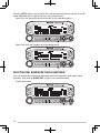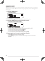
1
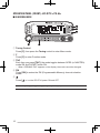
RC-D710
CONTROL PANEL
INSTRUCTION MANUAL
PANNEAU DE CONTROLE
MODE D’EMPLOI
PANEL DE CONTROL
MANUAL DE INSTRUCCIONES
コントロールパネル
取扱説明書
Only basic operations are explained in this instruction manual.
For a detailed explanation on the operations, refer to the PDF file
supplied on the CD-ROM.
Seules les fonctions de base sont expliquées dans ce mode
d’emploi. Pour le détail sur les autres opérations, reportez-vous au
fichier PDF à votre disposition sur le CD-ROM.
En este manual de instrucciones solamente se explican
las operaciones básicas. Si desea obtener una descripción
detallada de las operaciones, consulte el archivo PDF
correspondiente incluido en el CD-ROM.
本取扱説明書の操作説明は基本的な内容を記載しています。各機能の詳
細説明は付属CD-ROM内の取扱説明書(PDF形式)をご覧ください。
© B62‑2003‑00 (W)
09 08 07 06 05 04 03 02 01 00
RC-D710
INSTRUCTION MANUAL
ENGLISH
CONTROL PANEL
Thank You
We are grateful you decided to purchase this RC-D710. Features
RC-D710 has the following main features:
• Has a built-in TNC which conforms to the AX.25protocol. With a portable computer,
allows you to enjoy Packet operation quite easily.
• Includes a program for dealing with data formats supported by Automatic Packet/
Position Reporting System (APRS®).
• <RC-D710 + TM-V71>
When the RC-D710 is connected to the TM-V71A/E, the available functions are the
same as the TM-D710A/E.
• <RC-D710 + PG-5J>
When the RC-D710 is connected to the DATA terminal of a transceiver via the PG-5J
(option), with the RC-D710 built-in TNC, you can use PACKET and APRS mode (Stand
Alone mode).
Notices to the User
One or more of the following statements may be applicable:
FCC WARNING
This equipment generates or uses radio frequency energy. Changes or modifications to this
equipment may cause harmful interference unless the modifications are expressly approved in the
instruction manual. The user could lose the authority to operate this equipment if an unauthorized
change or modification is made.
INFORMATION TO THE DIGITAL DEVICE USER REQUIRED BY THE FCC
This equipment has been tested and found to comply with the limits for a Class B digital device,
pursuant to Part 15 of the FCC Rules. These limits are designed to provide reasonable protection
against harmful interference in a residential installation.
This equipment generates, uses and can generate radio frequency energy and, if not installed and
used in accordance with the instructions, may cause harmful interference to radio communications.
However, there is no guarantee that the interference will not occur in a particular installation. If
this equipment does cause harmful interference to radio or television reception, which can be
determined by turning the equipment off and on, the user is encouraged to try to correct the
interference by one or more of the following measures:
• Reorient or relocate the receiving antenna.
• Increase the separation between the equipment and receiver.
• Connect the equipment to an outlet on a circuit different from that to which the receiver is
connected.
• Consult the dealer for technical assistance.
Information on Disposal of Old Electrical and Electronic Equipment (applicable for EU
countries that have adopted separate waste collection systems)
Products with the symbol (crossed-out wheeled bin) cannot be disposed as household waste.
Old electrical and electronic equipment should be recycled at a facility capable of handling these items
and their waste byproducts. Contact your local authority for details in locating a recycle facility nearest
to you. Proper recycling and waste disposal will help conserve resources whilst preventing detrimental
effects on our health and the environment.
Precautions
Observe the following precautions to prevent fire, personal injury, and RC-D710/
transceiver damage.
• When operating mobile, do not attempt to configure the RC-D710 while driving; it is too
dangerous.
• Do not expose the RC-D710 to long periods of direct sunlight, nor place it near heating
appliances.
• Do not place the RC-D710 in excessively dusty, humid, or wet areas, nor on unstable
surfaces.
• If an abnormal odor or smoke is detected coming from the RC-D710 or transceiver,
switch the RC-D710/ transceiver power off immediately, and contact a Kenwood
service station or your dealer.
• Do not use options not specified by Kenwood.
Writing Conventions Followed in this Manual
The writing conventions described below have been followed to simplify
instructions and avoid unnecessary repetition.
Instruction
ii
Action
Press [KEY].
Momentarily press KEY.
Press [KEY] (1s).
Press and hold KEY for 1 second or longer.
Press [KEY1], [KEY2].
Press KEY1 momentarily, release KEY1, then press
KEY2.
Press [F], [KEY].
Press the F key to enter Function mode, then press
KEY to access its secondary function.
Press [KEY] + Power ON.
With the transceiver power OFF, press and hold
KEY while turning the transceiver power ON.
CONTENTS
PREPARATION................................................................................................. 1
Supplied Accessories........................................................................ 1
Installation........................................................................................... 2
Connection TO PC................................................................................. 3
Connection TO TM-V71......................................................................... 3
Connection TO PG-5J........................................................................... 4
GETTING ACQUAINTED.................................................................................. 6
OPERATION Panel (FRONT) <RC-D710 + TM-V71>.............................. 6
OPERATION Panel (REAR & LEFT)........................................................ 9
Display <RC-D710 + TM-V71>............................................................... 10
OPERATION Panel (FRONT) <RC-D710 + PG-5J>............................... 12
BASIC OPERATIONS (RC-D710 + TM-V71).................................................. 14
Switching THE Power ON/ OFF........................................................ 14
Adjusting the Volume...................................................................... 14
ADJUSTING THE SQUELCH.................................................................... 14
Selecting a BAND................................................................................ 15
SELECTING Dual band mode/ single band MODE....................... 16
SELECTING A frequency band........................................................ 17
Selecting an Operating mode...................................................... 18
Transmitting........................................................................................ 19
MENU MODE.................................................................................................. 20
Menu Access........................................................................................ 20
Menu Configuration......................................................................... 21
Character Entry............................................................................... 32
MAINTENANCE.............................................................................................. 34
GENERAL INFORMATION....................................................................... 34
SERVICE................................................................................................... 34
SERVICE NOTE........................................................................................ 34
CLEANING................................................................................................ 34
SPECIFICATIONS........................................................................................... 35
iii
For a detailed explanation on the operation, refer to the PDF file supplied on the CDROM.
• Titles denoted with <RC-D710 + TM-V71> are operation explanations only for
when the RC-D710 is connected to the TM-V71(A/E). Titles without this indication
include operation explanations for when connecting the RC-D710 to the PG-5J.
• In the explanations, the term "transceiver" is generally referring to the RC-D710 +
TM-V71(A/E).
Operation
File name
CONTENTS
00-CONTENTS-E.pdf
OPERATING THROUGH REPEATERS
<RC-D710 + TM-V71>
01-REPEATER-E.pdf
MEMORY CHANNELS <RC-D710 + TM-V71>
02-MEMORY CHANNEL-E.pdf
PROGRAMMABLE MEMORY (PM)
03-PM CHANNEL-E.pdf
SCAN <RC-D710 + TM-V71>
04-SCAN-E.pdf
CONTINUOUS TONE CODED SQUELCH SYSTEM
(CTCSS) <RC-D710 + TM-V71>
05-CTCSS-E.pdf
DIGITAL CODED SQUELCH (DCS)
<RC-D710 + TM-V71>
06-DCS-E.pdf
DUAL TONE MULTI-FREQUENCY (DTMF)
<RC-D710 + TM-V71>
07-DTMF-E.pdf
EchoLink® <RC-D710 + TM-V71>
08-EchoLink-E.pdf
OTHER OPERATIONS
09-OTHER OPERATIONS-E.pdf
PACKET OPERATION
10-PACKET-E.pdf
APRS
11-APRS-E.pdf
®
RESET
12-RESET-E.pdf
VGS-1 (OPTIONAL) OPERATION
<RC-D710 + TM-V71>
13-VGS-E.pdf
CROSS-BAND/ LOCKED-BAND OPERATION
<WITH TM-V71(A) K TYPE ONLY>
14-CROSS BAND (K TYPE)-E.pdf
WIRELESS OPERATION
<WITH TM-V71(A) K TYPE ONLY>
15-WIRELESS (K TYPE)-E.pdf
WEATHER ALERT
<WITH TM-V71(A) K TYPE ONLY>
16-WEATHER ALERT (K TYPE)-E.pdf
SKY COMMAND
<WITH TM-V71(A) K TYPE ONLY>
17-SKY COMMAND (K TYPE)-E.pdf
Note: Operations file is available in PDF file format. To read the file, you must use Adobe®
Reader®.
iv
PREPARATION
Supplied Accessories
Item
Part Number
Quantity
Modular plug cable (for PANEL jack)
E30-7639-XX
1
Line filter
L79-1417-XX
2
Cable with a 2.5 mm (1/10") 3-conductor plug (for
GPS jack)
E30-3400-XX
1
Base stand
J09-0409-XX
1
• Sheet
G11-4438-XX
1
Panel holder
J29-0663-XX
1
• Cushion
G13-2233-XX
1
Panel bracket
J29-0707-XX
1
• Sheet
G11-4228-XX
1
Screw set
N99-2055-XX
1
For USA/ CANADA
——
1
For Europe
——
1
English, French,
Spanish, Japanese
B62-2003-XX
1
Italian, German, Dutch,
Chinese (traditional)
B62-2004-XX
1
T93-0134-XX
1
Warranty Card
Instruction manual
CD-ROM (For a detailed explanation on the
operation)
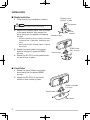
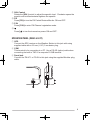
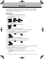
Installation
n Mobile Installation
Tapping screw
(4 mm x 12 mm)
1 Clean and dry the installation location.
Flat washer
Do not install the bracket close to an air bag.
2 Remove the release paper from the base
of the panel bracket, then secure it in
place using the 3 supplied self-tapping
Adhesive tape
screws.
Panel
bracket
• Allow the panel to set for a while, to ensure
it remains fast. Otherwise, vibrations may
occur.
• After removing the release paper, it cannot
be reused.
SEMS screw
(M4 x 10 mm)
3 Attach the panel holder to the panel
bracket using the 2 supplied SEMS
screws.
Panel holder
4 Attach the RC-D710 to the panel holder
so that it locks in place.
n Fixed Station
1 Attach the panel holder to the base
stand using the 2 supplied SEMS
screws.
2 Attach the RC-D710 to the panel
holder so that it locks in place.
SEMS screw (M4
x 10 mm)
Panel holder
Base stand
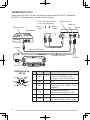
Connection TO PC
Use a PG-5G (option) cable when connecting the RC-D710 to a computer D-SUB
terminal.
COM terminal pin
NC
NC
NC
RXD
TXD
GND
CTS
RTS
PG-5G (option)
To PC 9-pin
D-SUB terminal
PG-5G pin configuration (cross connection)
CONNECTION TO TM-V71
Connect the RC-D710 to the TM-V71 using the supplied cable.
TM-V71
Panel jack
Line filter
RC-D710
Modular plug cable
Line filter
Panel jack
Installing the Line Filter
Install the line filter approximately 3 cm from the
connector.
Approx. 3 cm
Connection TO PG-5J
When using the RC-D710 with a transceiver other than the TM-V71, attach the
RC-D710 to the transceiver using the PG-5J (option).
To 13.8 V DC power supply
or 12 V vehicle battery
Panel jack
Red (+)
cable
Black (—)
cable
DATA terminal
DATA terminal
PG-5J
Transceiver
Line filter
DC power cable
6 pin mini-DIN cable
RC-D710
Modular plug cable
Line filter
Panel jack
DATA terminal pin
(PG-5J)
SQC
PR9
GND
NC
PKS
PKD
No.
Name
I/O
Function
q
PKD
O
TNC data output
2 Vp-p/ 10 kΩ (9600 bps data)
40 mVp-p/ 10 kΩ (1200 bps data)
w
GND
—
GND
e
PKS
O
Data standby control signal output
Open corrector TX : L level / RX : Hi
impedance
r
PR9
I
TNC data input (9600 bps)
350 mVp-p to 600 mVp-p/ 10 kΩ
t
NC
—
y
SQC
I
No connection
Squelch control signal input
SQL Open: H level / Close: L level
n Power Cable Connection (PG-5J)
Fixed Station
In order to use the PG-5J for fixed station operation, you will need a separate
13.8 V DC power supply that must be purchased separately.
Note: Do not plug the DC power supply into an AC outlet until you make all connections.
Mobile Installation
Be sure to use a 12 V vehicle battery that has sufficient current capacity. If the
current to the PG-5J is insufficient, the display may darken during transmission
or the transmit output power may drop excessively. Never connect the
transceiver to a 24 V battery.
Note: Install the PG-5J Interface Box using the included screw set in a location where it will
not interfere with driving.
n Replacing Fuses (PG-5J)
If the fuse blows, determine the cause, then correct the problem. After the
problem is resolved, replace the fuse. If newly installed fuses continue to
blow, disconnect the power cable and contact your authorized Kenwood
dealer or an authorized Kenwood service center for assistance.
Only use fuses of the specified type and rating; otherwise the PG-5J could be damaged.
Fuse
Fuse holder
GETTING ACQUAINTED
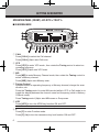
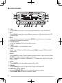
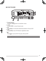
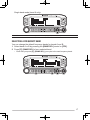
OPERATION Panel (FRONT) <RC-D710 + TM-V71>
n IN NORMALMODE
q CALL
Press [CALL] to select the Call channel. Press [CALL] (1s) to start Call scan. w VFO
Press [VFO] to enter VFO mode , then rotate the Tuning control to select an
operating frequency. Press [VFO] (1s) to start VFO scan. e MR
Press [MR] to enter Memory Channel mode, then rotate the Tuning control to
select a Memory channel.
Press [MR] (1s) to start Memory scan.
r Tuning Control
Rotate to select an operating frequency or Memory channel, change the scan
direction, etc. Press the Tuning control to enter MHz mode (while in VFO or Call mode) or to
toggle the display between the channel name and frequency (while in Memory
Channel mode).
Press Tuning control (1s) to start MHz scan or Group scan.
t KEY
Press [KEY] to turn the APRS key function ON and OFF.
Note: For APRS key functions, refer to the APRS explanation.
y F
Press [F] to enter Function mode.
Press [F] (1s) to turn the transceiver key lock function ON and OFF.
u TONE
Press [TONE] to turn the Tone function ON. Each time you press [TONE] to toggle the functions as follows: Tone ON >>
CTCSS ON >> DCS ON >> OFF.
i REV
Press [REV] to turn the Reverse function ON or OFF. Press [REV] (1s) to turn the Automatic Simplex Checker ON.
o LOW
Press [LOW] to toggle the transmit output power as follows: High Power (with
TM-V71(A/E) K, E types only) –> Middle Power –> Low Power.
!0 PF1
Press [PF1] to activate its programmable function. !1 PF2
Press [PF2] to activate its programmable function.
!2 BAND SEL (VOL) Control
Rotate the [BAND SEL] control to adjust the speaker volume. Press the left [BAND SEL] to select the A band. Press the right [BAND SEL]
to select the B band. Press [BAND SEL] (1s) to toggle between single and dual-band mode.
!3 SQL Control
Rotate the [SQL] control to adjust the squelch level. Clockwise opens the
squelch and counterclockwise tightens the squelch.
!4 TNC
Press [TNC] to turn built-in TNC ON and the APRS (or NAVITRA) mode ON.
Each time you press [TNC], the mode toggles as follows: APRS (or
NAVITRA) mode ON >> PACKET mode ON >> TNC OFF.
• When the built-in TNC turns on, “OPENING TNC” appears on the display.
• When “OPENING TNC” appears on the display, the mode cannot be changed.
!5 PM
Press [PM] to enters the PM (Programmable Memory) channel selection
mode. !6
Press [ ] to turn the transceiver power ON and OFF.
n IN FUNCTION MODE
q C.IN
Press [C.IN] to store the current operating frequency to the Call channel.
w M>V
Press [M>V] to copy the current Memory channel or Call channel to the VFO
(memory shift).
e M.IN
Select a Memory channel, then press [M.IN] to store the current operating
frequency in the Memory channel.
r Tuning Control
Press the Tuning control to enter Menu mode. t F OFF
Press [F OFF] to return Normal mode.
y T.SEL
While Tone, CTCSS, or DCS is ON, press [T.SEL] to enter CTCSS or DCS
setup mode.
u SHIFT
Press [SHIFT] to enter Offset Direction selection mode. Each time you press [SHIFT], the offset direction toggles as follows:
plus (+) direction –> minus (–) direction –> –7.6 MHz (with TM-V71(E) E type
only) –> OFF.
i MUTE
Press [MUTE] to turn the Mute function ON or OFF.
o VISUAL
Press [VISUAL] to turn the Visual Scan function ON and OFF.
!0 BAND SEL (VOL) Control
Rotate the [BAND SEL] control to adjust the speaker volume. Press [BAND SEL] to select a frequency band.
!1 SQL Control
Rotate the [SQL] control to adjust the squelch level. Clockwise opens the
squelch and counterclockwise tightens the squelch.
!2 DX
Press [DX] to turn the DX PacketClusters Monitor ON and OFF.
!3 P.IN
Press [P.IN] to enter PM Channel registration mode.
!4
Press [ ] to turn the transceiver power ON and OFF.
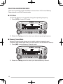
OPERATION Panel (REAR & LEFT)
qGPS
Connect the GPS receiver or the Weather Station to this jack with using
supplied cable with a 2.5 mm (1/10") 3-conductor plug.
w COM
This terminal is for connecting to a PC. Use a PG-5G (option) cable when
connecting the built-in TNC to a computer D-SUB terminal.
e Panel jack
Connect the TM-V71 or PG-5J to this jack using the supplied Modular plug
cable.
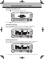
Display <RC-D710 + TM-V71>
<A Band>
Indicator
<B Band>
Description
Clock display (Setting Time: Menu 525)
Appears when there is a transmission band available. Blinks when the cross-band repeater is ON (with TM-V71(A) K
type only).
Appears when there is an operation band available. Blinks when the wireless remote control is ON (with TMV71(A) K type only).
Appears when the Tone function is ON.
Appears when the CTCSS function is ON.
Appears when the DCS function is ON.
Appears when the Shift function is set to plus.
Appears when the Shift function is set to minus.
Appears when the Reverse function is ON.
Appears when the ASC function is ON. Blinks when the ASC function is performing an OK check.
Appears while in AM mode.
Appears while in FM mode.
Appears while in Narrow FM mode.
Appears when the selected channel is registered while in
Memory Input mode.
10
Indicator
Description
Displays the Memory channel and Menu number.
Appears when the Memory Channel Lockout function is ON.
Appears while using High output power. Blinks when the temperature protection circuit (transmit power
save) turns on. (with TM-V71(A/E) K, E types only)
Appears while using Middle output power. Blinks when the temperature protection circuit (transmit power
save) turns on.
Appears while using Low output power.
Displays the operating frequency.
Appears when receiving a busy signal.
Performs as an S meter when receiving a signal and displays
the selected power level while transmitting.
Appears while transmitting.
Appears while using the External data band.
Appears while using the Internal data band.
Appears when the data terminal is set as 9600 (bps).
Appears when mute function is ON.
Appears while making a continuous recording.
Appears while in EchoLink Sysop mode.
Appears when the Key Lock function is ON.
Displays the PM channel number.
Appears when Weather Alert is ON. Blinks when receiving a signal. (with TM-V71(A) K type only)
11
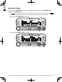
OPERATION Panel (FRONT) <RC-D710 + PG-5J>
n IN NORMALMODE
q Tuning Control
Press [F], then press the Tuning control to enter Menu mode. w F
Press [F] to enter Function mode.
eTNC
Each time you press [TNC], the mode toggles between APRS (or NAVITRA)
mode ON and PACKET mode ON.
• When “OPENING TNC” appears on the display, the mode cannot be changed.
r PM
Press [PM] to enters the PM (Programmable Memory) channel selection
mode. t
Press [ ] to turn the RC-D710 power ON and OFF.
Note: For [MSG], [LIST], [BCON], [POS], and [P.MON] keys, refer to the APRS explanation.
12
n IN FUNCTION MODE
q Tuning Control
Press the Tuning control to enter Menu mode. w F OFF
Press [F OFF] to return Normal mode.
eDX
Press [DX] to turn the DX PacketClusters Monitor ON and OFF.
r P.IN
Press [P.IN] to enter PM Channel registration mode.
t
Press [ ] to turn the RC-D710 power ON and OFF.
Note: For [WXi] key, refer to the APRS explanation.
13
BASIC OPERATIONS (RC-D710 + TM-V71)
Switching THE Power ON/ OFF
Press the [ ] switch to switch the transceiver ON.
Press the [ ] switch again to switch the transceiver OFF.
Adjusting the Volume
Rotate the [BAND SEL] (VOL) control of your selected band clockwise to
increase the volume and counterclockwise to decrease the volume.
ADJUSTING THE SQUELCH
Rotate the [SQL] control of your selected band, when no signals are present, and
select the squelch level at which the background noise is just eliminated.
14
Selecting a BAND
Press the left [BAND SEL] control to select band A and the right [BAND SEL]
control to select band B.
• The
icon appears at the top of the band on which you are operating and the
icon appears at the top of the band on which you are currently set to transmit.
Band A (left [BAND SEL] control):
Band B (right [BAND SEL] control):
15
Pressing [PF2] allows you to switch the operating band between bands A and B,
while maintaining the original band as the transmit band.
Band A is the transmit band and band B is the operating band:
Band A is both the transmit and operating band:
SELECTING Dual band mode/ single band MODE
You can switch the transceiver between dual band operation and single band
operation by pressing [BAND SEL] (1s) of your selected band.
16
Dual band mode:
Single band mode (band A only):
Note: You can also turn the center partition bar display off {Menu No. 527}.
SELECTING A frequency band
You can change the default frequency bands for bands A and B.
1 Select band A or B by pressing the [BAND SEL] control or [PF2].
2 Press [F], [BAND SEL] of your selected band.
• Each time you press [F], [BAND SEL], you cycle to the next frequency band.
17
Selecting an Operating mode
There are 3 operating modes available to choose from: VFO mode, Memory
Channel mode, and Call Channel mode.
■ VFO Mode
VFO mode allows you to manually change the operating frequency.
1 Press [VFO] to enter VFO mode.
2 Rotate the Tuning control to select your desired operating frequency.
■ Memory Channel Mode
Memory Channel mode allows you to quickly select a frequently used
frequency and related data which you have saved in the transceiver memory.
1 Press [MR] to enter Memory Channel mode.
2 Rotate the Tuning control to select your desired Memory channel.
18
■ Call Channel Mode
Call Channel mode allows you to quickly select a preset channel to allow
immediate calls on that frequency. The Call channel can be conveniently used
as an emergency channel within your group.
1 Select your desired band (A or B).
2 Press [CALL] to enter Call Channel mode.
• The
icon appears on the display.
3 Press [CALL] again to return to your previous operating frequency.
Transmitting
1 Select your desired band and frequency/channel.
2 Press and hold the microphone [PTT] switch and speak into the microphone to
transmit.
• The
icon and the RF power meter appear on the display for the selected
transmit band. The RF power meter shows the relative transmit output power.
• The / / icon(s) appear on the display, depending on what output power you
have selected.
3 When you finish speaking, release the [PTT] switch.
19
MENU MODE
Many functions on this RC-D710 are selected or configured through the Menu
instead of physical controls. Once you become familiar with the Menu system,
you will appreciate the versatility it offers.
Menu Access
1 Press [F], Tuning control to access the Menu.
• The setup category name appears on the display.
<RC-D710 + TM-V71>
<RC-D710 + PG-5J>
2 Rotate the Tuning control to select your desired setup category.
3 Press the Tuning control to set up the current category.
• The Menu name and number appears on the display.
4 Rotate the Tuning control to select your desired Menu.
5 Press the Tuning control to set up the current Menu.
6 Rotate the Tuning control to select your desired value for the selected Menu.
7 Press the Tuning control to set the selected value.
8 Repeat steps 2 to 7 to set up additional Menus.
• Press [ESC] at any time to exit Menu mode.
• Press [BACK] at any time to cancel the Menu setup and return to the Menu
selection.
20
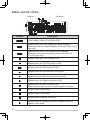
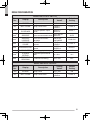
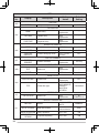
Menu Configuration
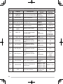
AUDIO <RC-D710 + TM-V71>
Menu
No.
Display
000
KEY BEEP
Setting
Values
Description
Default
Setting
Beep sound
OFF/ ON
ON
LEVEL 5
MODE 1
001
BEEP VOLUME
Beep volume level
LEVEL 1 ~
LEVEL 7
002
EXT.SPEAKER
External speaker output
mode
MODE 1/
MODE 2
003 1
ANNOUNCE
Voice announcement mode
OFF/ AUTO/
MANUAL
AUTO
004 1
ANNOUNCE
LANGUAGE
Voice announcement
language
ENGLISH/
JAPANESE
ENGLISH
005 1
ANNOUNCE
VOLUME
Voice announcement
volume
LEVEL 1 ~
LEVEL 7
LEVEL 5
006 1
ANNOUNCE SPEED
Voice announcement
speed
SPEED 0 ~
SPEED 4
SPEED 1
007 1
PLAYBACK REPEAT
Recording playback repeat
OFF/ ON
OFF
008 1
PLAYBACK
INTERVAL
Playback repeat interval
time
0 ~ 60 s
10 s
009 1
CONTINUOUS
RECORDING
Continuous recording
OFF/ ON
OFF
AUDIO <RC-D710 + PG-5J>
Menu
No.
Display
000
KEY BEEP
001
BEEP VOLUME
Description
Setting
Values
Beep sound
OFF/ ON
Beep volume level
LEVEL 1 ~
LEVEL 3
Default
Setting
ON
LEVEL 2
21
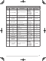
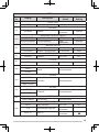
TX/RX <RC-D710 + TM-V71>
Menu
No.
Display
100
PROGRAMMABLE
VFO
101
STEP
102
MODULATION
103
104
105
Setting
Values
Default
Setting
Programmable VFO setup
Varies with
the selected
frequency band
–
Step frequency
Varies with
the selected
frequency band
–
Modulation/demodulation
mode
Varies with
the selected
frequency band
–
VHF AIP
VHF band AIP
OFF/ ON
OFF
UHF AIP
UHF band AIP
OFF/ ON
OFF
OFF/ ON
OFF
Description
S-METER SQUELCH S-meter squelch
106
S-METER SQL
HANGUP TIME
S-meter squelch hang up
time
OFF/ 125/ 250/
500 ms
OFF
107
MUTE HANGUP
TIME
Mute hang up time setup
OFF/ 125/ 250/
500/ 750/ 1000
ms
OFF
108
BEAT SHIFT
Beat shift
OFF/ ON
OFF
109
TOT
Time-out timer
3/ 5/ 10 min
110 2
WEATHER ALERT
Weather alert
OFF/ ON
10 min
OFF
MEMORY <RC-D710 + TM-V71>
Menu
No.
Display
200
MEMORY NAME
201
RECALL METHOD
202
LOCKOUT
203
GROUP LINK
204
EchoLink MEMORY
Description
Setting
Values
Memory name setup
Up to 8
characters
Memory channel recall
method
ALL BANDS/
CURRENT
Memory channel lockout
OFF/ ON
Memory group link
registration
Up to 10 digits
(0 ~ 9)
EchoLink memory setting
Up to 8
characters
for EchoLink
memory name
Default
Setting
–
ALL BANDS
OFF
–
–
Up to 8 digits
for DTMF code
205
22
EchoLink SPEED
EchoLink memory
transmission speed
FAST/ SLOW
FAST
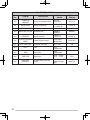
DTMF <RC-D710 + TM-V71>
Menu
No.
Display
300
DTMF HOLD
301
Description
DTMF MEMORY
Setting
Values
DTMF transmission hold
OFF/ ON
DTMF memory
Up to 8
characters for
DTMF memory
name
Default
Setting
OFF
–
Up to 16 digits
for DTMF code
302
DTMF SPEED
DTMF memory
transmission speed
FAST/ SLOW
FAST
303
DTMF PAUSE
DTMF pause code time
100/ 250/ 500/
750/ 1000/
1500/ 2000 ms
500 ms
304
DTMF KEY LOCK
DTMF key lock
OFF/ ON
OFF
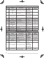
REPEATER <RC-D710 + TM-V71>
Menu
No.
Display
400
OFFSET FREQUENCY
401 3
AUTO REPEATER
OFFSET
402
1750 TX HOLD
403 2
REPEATER MODE
404 2
REPEATER TX HOLD
405 2
REPEATER ID
406 2
REPEATER ID TX
Description
Setting
Values
Default
Setting
Offset frequency
See
explanation
Auto Repeater Offset
OFF/ ON
ON
Transmission hold when
OFF/ ON
transmitting a 1750 Hz tone
OFF
Repeater mode
CROSS BAND/
LOCKED TX:
A-BAND/
LOCKED TX:
B-BAND
Repeater transmission hold
ON/ OFF
Repeater ID registration
Up to 12
characters
Repeater ID transmission
OFF/ MORSE/
VOICE
–
CROSS BAND
OFF
–
OFF
23
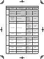
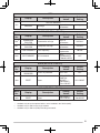
AUX <RC-D710 + TM-V71>
Menu
No.
Display
500
POWER ON
MESSAGE
501
BRIGHTNESS
502
503
Description
Setting
Values
Default
Setting
Power on message setup
Up to 8
characters
HELLO !!
Display brightness
OFF/ LEVEL 1
~ LEVEL 8
LEVEL 8
AUTO BRIGHTNESS Display auto brightness
OFF/ ON
OFF
BACKLIGHT COLOR Backlight color
AMBER/
GREEN
AMBER
Display contrast
LEVEL 1 ~
LEVEL 16
LEVEL 8
Display reverse mode
POSITIVE/
NEGATIVE
POSITIVE
See
explanation
504
CONTRAST
505
DISPLAY REVERSE
MODE
WX CH
(K type)
507
PANEL PF1
PF1 key programmable
function value
508
PANEL PF2
PF2 key programmable
function value
See
explanation
CTRL
509
MIC PF1(PF)
Microphone PF1 key
programmable function
value
See
explanation
A/B
510
MIC PF2(MR)
Microphone PF2 key
programmable function
value
See
explanation
MR
511
MIC PF3(VFO)
Microphone PF3 key
programmable function
value
See
explanation
VFO
512
MIC PF4(CALL)
Microphone PF4 key
programmable function
value
See
explanation
513
MIC KEY LOCK
Microphone key lock
OFF/ ON
OFF
514
SCAN RESUME
Scan resume method
TIME/
CARRIER/
SEEK
TIME
515
VISUAL SCAN
Number of Channels for
Visual Scan
MODE 1: 31ch/
MODE 2 : 61ch/
MODE 3 : 91ch/
MODE 4 : 181ch
516
APO
Auto Power Off time
OFF/ 30/ 60/
90/ 120/ 180
(minutes)
24
FRQ.BAND
(E/ M4 types)
CALL
(K/ M4 types)
1750
(E type)
MODE 2 : 61ch
OFF
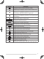
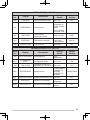
AUX <RC-D710 + TM-V71>
Menu
No.
Display
Description
Setting
Values
Default
Setting
A-BAND
517
EXT. DATA BAND
External TNC data band
type
A-BAND/
B-BAND/
TX:A-BAND
RX:B-BAND/
RX:A-BAND
TX:B-BAND
518
EXT. DATA SPEED
External TNC data
communications speed
1200/ 9600 bps
1200 bps
519
PC PORT
BAUDRATE
PC terminal baud rate
speed
9600/ 19200/
38400/ 57600
bps
9600 bps
520
SQC SOURCE
SQC output type
OFF/ BUSY/
SQL/ TX/
BUSY or TX/
SQL or TX
BUSY or TX
521
AUTO PM STORE
Automatic PM entry
OFF/ ON
ON
522 2
REMOTE ID
Personal Identification
Number
000 ~ 999
000
523 2
REMOTE ANSWER
BACK
Answer back
OFF/ ON
ON
524
DATE
Date
See
explanation
–
525
TIME
Clock time
See
explanation
–
526
TIME ZONE
Time zone
UTC + 14:00 ~
UTC − 14:00
UTC
527
DISPLAY
PARTITION BAR
Display partition bar
OFF/ ON
ON
528
COM PORT
BAUDRATE
COM terminal baud rate
speed
9600/ 19200/
38400/ 57600
bps
9600 bps
Internal TNC data band
(PACKET)
A-BAND/
B-BAND/
TX:A-BAND
RX:B-BAND/
RX:A-BAND
TX:B-BAND
A-BAND
529
INT. DATA BAND
(PACKET)
25
AUX <RC-D710 + PG-5J>
Menu
No.
Display
500
POWER ON
MESSAGE
501
BRIGHTNESS
502
503
Description
Setting
Values
Default
Setting
Power on message setup
Up to 8
characters
HELLO !!
Display brightness
OFF/ LEVEL 1
~ LEVEL 8
LEVEL 8
AUTO BRIGHTNESS Display auto brightness
OFF/ ON
OFF
BACKLIGHT COLOR Backlight color
AMBER/
GREEN
AMBER
Display contrast
LEVEL 1 ~
LEVEL 16
LEVEL 8
Display reverse mode
POSITIVE/
NEGATIVE
POSITIVE
Automatic PM entry
OFF/ ON
504
CONTRAST
505
DISPLAY REVERSE
MODE
521
AUTO PM STORE
524
DATE
Date
See
explanation
–
525
TIME
Clock time
See
explanation
–
526
TIME ZONE
Time zone
UTC + 14:00 ~
UTC − 14:00
UTC
528
COM PORT
BAUDRATE
COM terminal baud rate
speed
9600/ 19200/
38400/ 57600
bps
9600 bps
26
ON
APRS
Menu
No.
Display
Description
Setting
Values
Default
Setting
BASIC SETTING
600
MY CALLSIGN
Call sign entry
Up to 9
characters
NOCALL
BEACON TYPE
Beacon type
APRS/
NAVITRA
APRS
INTERNAL TNC
DATA BAND
*RC-D710 +
TM-V71
DATA SPEED
Data band type
A-BAND/
B-BAND/
TX:A-BAND
RX:B-BAND/
RX:A-BAND
TX:B-BAND
A-BAND
Data communications
speed
1200/ 9600 bps
1200 bps
D or RxD
BAND/
BOTH BAND/
IGNORE DCD
D or RxD
BAND
601
DCD SENSE
DCD sense type
*RC-D710 +
TM-V71
ON/
IGNORE DCD
*RC-D710 +
PG-5J
TX DELAY
100/ 150/ 200/
300/ 400/ 500/
750/ 1000 ms
TX delay time
ON
200 ms
GPS PORT
BAUD RATE
602
INPUT
OUTPUT
Baud rate speed
2400/ 4800/
9600 bps
GPS data input type
OFF/ GPS/
WEATHER(Da
vis)/ WEATHER
(PeetBros)
OFF
GPS data output type
OFF/
WAYPOINT/
DGPS
OFF
4800 bps
WAYPOINT
FORMAT
Way point format
NMEA/
MAGELLAN/
KENWOOD
NMEA
NAME
Way point name
6-CHAR ~ 9CHAR
6-CHAR
Way point output type
ALL/ LOCAL/
FILTERED
ALL
603
OUTPUT
27
APRS
Menu
No.
604
Display
Setting
Values
Description
Default
Setting
COM PORT
OUTPUT
COM port output
OFF/ ON
OFF
MY POSITION
NAME
605
LATITUDE
LONGITUDE
Name entry
See
explanation
−
Latitude entry
See
explanation
−
Longitude entry
See
explanation
−
BEACON INFORMATION
606
SPEED
Speed information setup
OFF/ ON
ON
ALTITUDE
Altitude information setup
OFF/ ON
ON
POSITION
AMBIGUITY
Position ambiguity mode
OFF/ 1-DIGIT ~
4-DIGIT
OFF
POSITION COMMENT
607
POSITION
COMMENT
See
explanation
Off Duty
Status text
See
explanation
−
Status text TX rate
OFF/ 1/1 ~ 1/8
Position comment
STATUS TEXT
608
TEXT
TX RATE
1/1
PACKET FILTER
POSITION LIMIT
Position limit
See
explanation
Packet filter type
WHEATHER/
DIGI/ MOBILE/
OBJECT/
NAVITRA/
OTHERS
609
TYPE
OFF
Checked all
STATION ICON
610
STATION ICON
Station icon
See
explanation
W
(KENWOOD icon)
BEACON TX ALGORITHM
METHOD
611
INITIAL INTERVAL
Method
MANUAL/ PTT/
AUTO
MANUAL
Initial interval time
0.2/ 0.5/ 1/ 3/ 5/
10/ 20/ 30 min
3 min
DECAY ALGORITHM Decay algorithm
PROPORTIONAL
PATHING
28
Proportional pathing
OFF/ ON
ON
OFF/ ON
ON
APRS
Menu
No.
612
Display
Setting
Values
Description
Default
Setting
PACKET PATH
TYPE
Packet path type
See explanation
NETWORK
613
NETWORK
Up to 9
characters
Network
APK102
VOICE ALERT *RC-D710 + TM-V71
614
VOICE ALERT
Voice alert
OFF/ ON
CTCSS FREQUENCY CTCSS frequency
See
explanation
OFF
100.0 Hz
WEATHER STATION
615
TX
TX INTERVAL
616
617
Weather TX
OFF/ ON
OFF
Weather TX interval time
5/ 10/ 30 min
5 min
DIGIPEAT (MY CALL)
DIGIPEAT
Digipeat
OFF/ ON
OFF
UI CHECK
TIME
UI check time
0 ~ 250 sec
28 sec
UIDIGI
618
UIDIGI
ALIASES
UIDIGI
See explanation
UIFLOOD
619
UIFLOOD
ALIASES
UIFLOOD
See explanation
SUBSTITUTION
UITRACE
620
UITRACE
ALIASES
621
UITRACE
See explanation
USER PHRASES
USER PHRASES
User phrases
See explanation
AUTO MESSAGE REPLY
REPLY
622
TEXT
REPLY TO
Reply message
OFF/ ON
Auto message reply text
Up to 50
characters
Reply to
Up to 9
characters
OFF
−
29
APRS
Menu
No.
Display
Setting
Values
Description
Default
Setting
GROUP FILTERING
623
MESSAGE
BLN
Message group
Up to 59
characters
ALL, QST, CQ,
KWD
BLN group
Up to 29
characters
−
SOUND
RX Beep
OFF/ MESSAG
E ONLY/ MINE/
ALL NEW/ ALL
SPECIAL CALL
Special call
Up to 9
characters
APRS VOICE
*RC-D710 +
TM-V71
APRS voice
OFF/ ON
RX BEEP
624
ALL
−
ON
INTERRUPT DISPLAY
OFF/ HALF/
ENTIRE
625
DISPLAY AREA
*RC-D710 +
TM-V71
Display area
OFF/ ENTIRE
*RC-D710
+PG-5J
AUTO BRIGHTNESS Auto brightness
CHANGE COLOR
Change color
ENTIRE
ENTIRE
OFF/ ON
ON
OFF/ ON
ON
DISPLAY UNIT 1
626
Speed/ distance
mi/h mile/ Km/h
mile/ Knots nm
mi/h mile
ALTITUDE, RAIN
Altitude/ rain
feet/inch/ m/nm
feet/inch
TEMPERATURE
Temperature
°F/ °C
SPEED, DISTANCE
°F
DISPLAY UNIT 2
POSITION
Position format
dd°mm. mm’/
dd°mm’ ss. s”
dd°mm. mm’
Grid format
MAIDENHEAD
GRID/ SAR
GRID (CONV)/
SAR GRID
(CELL)
MAIDENHEAD
GRID
627
GRID FORMAT
NAVITRA GROUP
628
30
GROUP MODE
Group mode
OFF/ ON
OFF
GROUP CODE
Group code
3 characters
000
APRS
Menu
No.
Display
Setting
Values
Description
Default
Setting
NAVITRA MESSAGE
629
MESSAGE
Message
Up to 20 characters
−
SKY CMD (RC-D710 + TM-V71)
Menu
No.
Display
Setting
Values
700 2
COMMANDER
CALLSIGN
Commander call sign
Up to 9
characters
NOCALL
701 2
TRANSPORTER
CALLSIGN
Transporter call sign
Up to 9
characters
NOCALL
702 2
TONE FREQUENCY
Tone frequency
See
explanation
88.5Hz
703 2
SKY COMMAND
SKY command
OFF/
COMMANDER/
TRANSPORTER
Description
Default
Setting
OFF
AUX 2 (RC-D710 + TM-V71)
Menu
No.
Display
998
POWER ON
PASSWORD
999
RESET
Setting
Values
Description
Power on password
OFF/ ON
Reset
VFO RESET/
PARTIAL
RESET/
PM RESET/
FULL RESET
Default
Setting
OFF
VFO RESET
AUX 2 (RC-D710 + PG-5J)
Menu
No.
Display
999
RESET
1
2
3
Description
Reset
Setting
Values
PM RESET/
FULL RESET
Default
Setting
PM RESET
Available only when the optional VGS-1 unit is installed in the TM-V71(A/E).
Available only for TM-V71(A) K type models.
Available only for TM-V71(A/E) K and E types models.
31
Character Entry
Certain menus require you to enter characters, such as the power on message
and memory names. When character entry is required, a cursor will appear on
the display.
1 Press the Tuning control.
• The cursor will blink.
2 Rotate the Tuning control to select your desired character.
3 Press the Tuning control to set the selected character.
• The cursor will move to the next digit.
•
•
•
•
You can move the cursor to the left or right by pressing [←] or [→].
You can insert one space by pressing [SPACE].
You can insert a character by pressing [INS].
You can delete the selected character by pressing [CLR].
4 Repeat steps 2 and 3 to enter the remaining characters.
• Press [ESC] at any time to exit Menu mode.
• Press [BACK] at any time to cancel the Menu setup and return to the Menu
selection.
32
n Microphone Keypad Character Entry (with TM-V71)
The microphone keys can also be used to enter characters. Refer to the table
below for characters corresponding to microphone keys.
Key
Character Display (with
each press of the key)
1
Q
Z
1
2
A
B
C
3
D
E
4
G
5
6
Key
Character Display (with
each press of the key)
7
P
R
S
7
2
8
T
U
V
8
F
3
9
W
X
Y
9
H
I
4
0
J
K
L
5
M
N
O
6
(space)
0
Not used
#
–
/
@
For a memory name, status text, and message:
Key
Character Display (with each press of the key)
1
q
z
1
Q
2
a
b
c
2
A
B
C
3
d
e
f
3
D
E
F
4
g
h
i
4
G
H
I
5
j
k
l
5
J
K
L
6
m
n
o
6
M
N
O
7
p
r
s
7
P
R
S
8
t
u
v
8
T
U
V
9
w
x
y
9
W
X
Y
0
(space)
0
Z
Not used
#
?
!
’
.
,
–
/
&
#
%
(
)
<
>
;
:
”
@
The microphone [A] ~ [D] keys have special functions assigned to them:
[A]: Functions the same as [CLR]
[B]: Functions the same as [←]
[C]: Functions the same as [→]
[D]: Functions the same as the Tuning control
33
MAINTENANCE
GENERAL INFORMATION
This product has been factory aligned and tested to specification before shipment.
Attempting service or alignment without factory authorization can void the product
warranty.
SERVICE
When returning this product to your dealer or service center for repair, pack it in
its original box and packing material. Include a full description of the problem(s)
experienced. Include your telephone number along with your name and address
in case the service technician needs to contact you; if available, also include your
fax number and e-mail address. Don’t return accessory items unless you feel
they are directly related to the service problem.
You may return this product for service to the authorized Kenwood dealer from
whom you purchased it, or any authorized Kenwood service center. Please do
not send subassemblies or printed circuit boards; send the complete product. A
copy of the service report will be returned with the product.
SERVICE NOTE
If you desire to correspond on a technical or operational problem, please make
your note legible, short, complete, and to the point. Help us help you by providing
the following:
• Model and serial number of equipment
• Question or problem you are having
• Other equipment in your station pertaining to the problem
Do not pack the equipment in crushed newspapers for shipment! Extensive damage may result
during rough handling or shipping.
Note:
u Record the date of purchase, serial number and dealer from whom this product was purchased.
u For your own information, retain a written record of any maintenance performed on this
product.
u When claiming warranty service, please include a photocopy of the bill of sale or other
proof-of-purchase showing the date of sale.
CLEANING
To clean the case of this product, use a neutral detergent (no strong chemicals)
and a damp cloth.
34
SPECIFICATIONS
Specifications are subject to change without notice due to advancements in
technology.
Supply voltage
10 V DC (9 ~ 11 V DC) <Negative ground>
Current
Less than 450 mA
Operating temperature range
Dimensions
(W x H x D)
–20°C ~ +60°C (–4°F ~ +140°F)
Without projections
155 x 70 x 38 mm (6.10" x 2.76" x 1.50")
With projections
156 x 71 x 56 mm (6.14" x 2.80" x 2.21")
Weight (approx.)
300 g (10.6 oz.)
To download the MCP-2A software, go to:
http://www.kenwood.com/i/products/info/amateur/software_download.html
Note: This URL may change without notice.
35