1
CD-RECEIVER
KDC-X689
INSTRUCTION MANUAL
Take the time to read through this instruction manual.
Familiarity with installation and operation procedures will help you obtain the best
performance from your new CD-receiver.
For your records
Record the serial number, found on the back of the unit, in the spaces designated on the
warranty card, and in the space provided below. Refer to the model and serial numbers
whenever you call upon your Kenwood dealer for information or service on the product.
Model KDC-X689 Serial number
US Residence Only
Register Online
Register your Kenwood product at
www.kenwoodusa.com
© B64-3147-00/00 (KW)
B64-3147-00_K_English.indd 1
05.5.9 2:32:18 PM
Contents
Safety precautions
4
Notes
5
Warning
6
About CDs
7
About AAC, MP3 and WMA
8
General features
9
Power
Hiding the Control Panel
Selecting the Source
Volume
Attenuator
System Q
Speaker Setting
Audio Control
Audio Setup
Subwoofer Output
Display Setting
Text Selection for Display
Text Display Switching
Graphic part/ Spectrum Analyzer Display
Switching
Station/Disc Naming (SNPS/DNPS)
Faceplate Angle Adjustment
Theft Deterrent Faceplate
TEL Mute
Tuner features
Tuning
Tuning Mode
Direct Access Tuning
Station Preset Memory
Auto Memory Entry
Preset Tuning
2 |
CD/Audio file/External disc control
features
23
Playing CD & Audio file
Playing External Disc
Fast Forwarding and Reversing
Track/File Search
Disc Search/Folder Search
Direct Track/File Search
Direct Disc Search
Track/File/Disc/Folder Repeat
Scan Play
Random Play
Magazine Random Play
Disc Random Play
Folder Select
Switching the Play mode
Letter Seek
Text/Title Scroll
HD Radio control features
28
Tuning
Menu system
21
29
Menu System
Security Code
Touch Sensor Tone
Manual Clock Adjustment
Date Adjustment
Date Mode
Dimmer
OFF Wait Time Setting
Built-in Amp Setting
Dual Zone System Setting
B.M.S. (Bass Management System)
B.M.S. Frequency Offset
AMP Control
CRSC (Clean Reception System Circuit)
Receive mode Setting
SIRIUS ID (ESN) display
Auxiliary Input Display Setting & Station/Disc
Naming
Text Scroll
Built-in Auxiliary input Setting
CD Read Setting
Voice Index
ACDrive firmware version display
Unique ID display
Audio Preset Memory
Audio Preset Call
Demonstration mode Setting
English
B64-3147-00_K_English.indd 2
05.5.9 2:32:19 PM
Basic Operations of remote control 36
Accessories/ Installation Procedure 39
Connecting Wires to Terminals
40
Installation
41
Removing the Unit
43
Troubleshooting Guide
44
Specifications
47
The "AAC" logo is trademark of Dolby
Laboratories.
English |
B64-3147-00_K_English.indd 3
3
05.5.9 2:32:19 PM
Safety precautions
2WARNING
To prevent injury or fire, take the
following precautions:
• To prevent a short circuit, never put or leave any
metallic objects (such as coins or metal tools)
inside the unit.
2CAUTION
To prevent damage to the machine, take
the following precautions:
• Make sure to ground the unit to a negative 12V
DC power supply.
• Do not install the unit in a spot exposed to direct
sunlight or excessive heat or humidity. Also avoid
places with too much dust or the possibility of
water splashing.
• Do not place the faceplate or the faceplate case in
areas exposed to direct sunlight, excessive heat or
humidity. Also avoid places with too much dust or
the possibility of water splashing.
• To prevent deterioration, do not touch the
terminals of the unit or faceplate with your
fingers.
• Do not subject the faceplate to excessive shock,
as it is a piece of precision equipment.
• When replacing a fuse, only use a new fuse with
the prescribed rating. Using a fuse with the wrong
rating may cause your unit to malfunction.
• Do not apply excessive force to the open
faceplate or place objects on it. Doing so will
cause damage or breakdown.
• Do not use your own screws. Use only the screws
provided. If you use the wrong screws, you could
damage the unit.
Attach the panel while you are on the
vehicle
The panel lock arm appears when the panel is
removed. Therefore, the panel must be attached
while the electrical system of the car is operating.
About CD players/disc changers
connected to this unit
Kenwood disc changers/ CD players released in
1998 or later can be connected to this unit.
Refer to the catalog or consult your Kenwood
dealer for connectable models of disc changers/
CD players.
Note that any Kenwood disc changers/ CD players
released in 1997 or earlier and disc changers made
by other makers cannot be connected to this unit.
Connecting unsupported disc changers/CD players
to this unit may result in damage.
Set the "O-N" Switch to the "N" position for the
applicable Kenwood disc changers/ CD players.
The functions you can use and the information
that can be displayed may differ depending on the
models being connected.
• You can damage both your unit and the CD changer if
you connect them incorrectly.
LX-bus connection
The LX AMP and the sensor unit must be connected
one at a time.
Lens Fogging
When you turn on the car heater in cold weather,
dew or condensation may form on the lens in the
CD player of the unit. Called lens fogging, this
condesnation on the lens may not allow CDs to
play. In such a situation, remove the disc and wait
for the condensation to evaporate. If the unit still
does not operate normally after a while, consult
your Kenwood dealer.
Faceplate
• Use the enclosed or dedicated faceplate. Using a
faceplate other than the specified one may cause
your unit to malfunction.
Do Not Load 3-in. CDs in the CD slot
If you try to load a 3 in. CD with its adapter into the
unit, the adapter might separate from the CD and
damage the unit.
NOTE
This Class B digital apparatus complies with
Canadian ICES-003.
4 |
English
B64-3147-00_K_English.indd 4
05.5.9 2:32:19 PM
Notes
• If you experience problems during installation,
consult your Kenwood dealer.
• If the unit fails to operate properly, press the Reset
button to restore factory settings.
• Press the reset button if the disc auto changer fails
to operate correctly. Normal operation should be
restored.
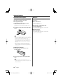
Before using this unit for the first time
This unit is initially set on the Demonstration mode.
When using this unit for the first time, cancel the
<Demonstration mode Setting> (page 35).
About SIRIUS Satellite radio tuner
Refer to the instruction manual of SIRIUS Satellite
radio tuner KTC-SR901/SR902/SR903 (optional
accessory) when connected, for the operation
method.
• Refer to the sections of A models for operations.
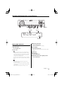
4
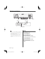
Reset button
• We recommend the use of <Security Code>
(page 30) to prevent theft.
• The characters conforming to ISO 8859-1
character set can be displayed.
• There are places in this manual where lit
indicators are described; however, the only time
an indicator will light is in the following settings.
When Indicator is selected as mentioned in <Text
Display Switching> (page 15)
• The illustrations of the display and the panel
appearing in this manual are examples used to
explain more clearly how the controls are used.
Therefore, what appears on the display in the
illustrations may differ from what appears on the
display on the actual equipment, and some of the
illustrations on the display may be inapplicable.
AUTO
1—6
38
FM/SCRL ¢
SRC
AM
Cleaning the Unit
If the faceplate of this unit is stained, wipe it with a
dry soft cloth such as a silicon cloth.
If the faceplate is stained badly, wipe the stain off
with a cloth moistened with neutral cleaner, then
wipe it again with a clean soft dry cloth.
• Applying spray cleaner directly to the unit may affect its
mechanical parts. Wiping the faceplate with a hard cloth
or using a volatile liquid such as thinner or alcohol may
scratch the surface or erases characters.
Cleaning the Faceplate Terminals
If the terminals on the unit or faceplate get dirty,
wipe them with a clean soft dry cloth.
English |
B64-3147-00_K_English.indd 5
5
05.5.9 2:32:20 PM
Notes
2Warning
About DAB Tuner control
2CAUTION
Refer to A group on the Instruction manual of DAB
Tuner KTC-9090DAB (optional accessory) for the
control method of DAB Tuner function.
However, the following control methods of the
function for this unit may be differed from the
Instruction manual; therefore, refer to the following
supplemental instruction.
<Auto Ensemble Memory Entry>
1. Select the preset band for Auto Ensemble
Memory Entry.
2. Press the [AME] button for at least 2 seconds.
Open Auto Ensemble Memory Entry.
After storing in the memory finishes, the
number of the pre-set buttons and the
ensemble label are displayed.
<Searching by programme type and language>
and <Languages to be displayed> in
<Programme Type (PTY) Function>
At the operation to press [DISP] button, press
[AUTO] button.
About "Media Manager" of PC application
attached to KDC-X689
• "Media Manager" is recorded in the CD-ROM
attached to this unit.
• Refer to the attached installation manual for the
installation method of "Media Manager".
• Refer to the user’s manual recorded in the
installation CD-ROM and Help of "Media Manager"
for the operation method of "Media Manager".
• The unit can play CD (hereafter called "ACDrive
disc") created by "Media Manager".
• Refer to the following site for the updated
information of "Media Manager".
http://www.kenwood.mediamanager.jp
• Contact Kenwood for the function and operation
of the "Media Manager".
• "Media Manager" is a product of PhatNoise.
6 |
Use of controls or adjustments or performance of
procedures other than those specified herein may
result in hazardous radiation exposure.
In compliance with Federal Regulations, following
are reproductions of labels on, or inside the product
relating to laser product safety.
kenwood CORPORATION
2967-3, ISHIKAWA-MACHI,
HACHIOJI-SHI
TOKYO, JAPAN
kenwood CORP. CERTIFIES THIS EQUIPMENT
CONFORMS TO DHHS REGULATIONS N0.21 CFR
1040. 10, CHAPTER 1, SUBCHAPTER J.
Location : Bottom Panel
FCC WARNING
This equipment may generate or use radio
frequency energy. Changes or modifications to
this equipment may cause harmful interference
unless the modifications are expressly approved
in the instruction manual. The user could lose
the authority to operate this equipment if an
unauthorized change or modification is made.
NOTE
This equipment has been tested and found to
comply with the limits for a Class B digital device,
pursuant to Part 15 of the FCC Rules. These limits
are designed to provide reasonable protection
against harmful interference in a residential
installation. This equipment may cause harmful
interference to radio communications, if it is
not installed and used in accordance with the
instructions. However, there is no guarantee
that interference will not occur in a particular
installation. If this equipment does cause harmful
interference to radio or television reception, which
can be determined by turning the equipment off
and on, the user is encouraged to try to correct
the interference by one or more of the following
measures:
• Reorient or relocate the receiving antenna.
• Increase the separation between the equipment
and receiver.
• Connect the equipment into an outlet on a
circuit different from that to which the receiver is
connected.
• Consult the dealer or an experienced radio/TV
technician for help.
English
B64-3147-00_K_English.indd 6
05.5.9 2:32:20 PM
About CDs
Handling CDs
Removing CDs
• Do not touch the recording surface of the CD.
When removing CDs from this unit pull them out
horizontally.
CDs that cannot be used
• CDs that are not round cannot be used.
• CD-R and CD-RW are easier to damage than a
normal music CD. Use a CD-R or a CD-RW after
reading the caution items on the package etc.
• Do not stick tape etc. on the CD, or use a CD with
tape stuck on it.
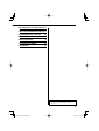
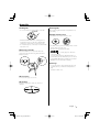
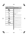
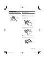
When using a new CD
If the CD center hole or outside rim has burrs,
use the CD only after removing the burrs with a
ballpoint pen etc.
Burrs
Burrs
• CDs with coloring on the recording surface or CDs
that are dirty cannot be used.
• This unit can only play the CDs with
.
This unit may not correctly play discs which do
not have the mark.
• You cannot play A CD-R or CD-RW that has not
been finalized. (For the finalization process refer to
your CD-R/CD-RW writing software, and your CDR/CD-RW recorder instruction manual.)
CD storage
• Do not place CDs in direct sunlight (On the seat
or dashboard etc.) or where the temperature is
high.
• Store CDs in their cases.
CD accessories
Do not use disc type accessories.
CD cleaning
Clean from the center of the disc and move
outward.
English |
B64-3147-00_K_English.indd 7
7
05.5.9 2:32:20 PM
About AAC, MP3 and WMA
The playable AAC/MP3/WMA file (hereafter called
Audio file) and the media format has the following
limitation. The Audio file, which is not comforming
to the specification, may not play normally, or the
file and folder names may not display correctly.
• Attach the correct extension for the Audio file
(AAC: ".M4A", MP3: ".MP3", WMA: ".WMA")
• Do not attach the extensions to files other than the
Audio file. If the extension is attached, the file, which is
not the Audio file, will play and outputs a loud noise,
causing damage to the speaker.
• The files with copy protection cannot be played.
Playable AAC file
• ".m4a" file encoded by AAC-LC format.
Refer to http://www.kenwood.mediamanager.jp
for the details.
Playable MP3 file
• MPEG 1/2 Audio Layer 3 file
• Transfer bit rate: 8-320 kbps
• Sampling frequency
: 16, 22.05, 24, 32, 44.1, 48 kHz
Playable WMA file
• The file in accordance with Windows Media Audio
(Except for the file for Windows Media Player 9 or
after which applies the new functions)
• Transfer bit rate: 48-192 kbps
• Sampling frequency: 32, 44.1, 48 kHz
The maximum number of characters for
display
File/Folder name: 128 characters
MP3 ID3 Tag/ WMA Contents property:
30 characters
AAC song information: 60 characters
• File/Folder name is the number of the characters
including the extensions
• AAC ID3 Tag cannot be displayed.
Limitation of structure for the file and the
folder
• Maximum number of directory levels: 8
• Maximum number of folders: 100
• Maximum number of files per folder: 4096
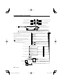
Playing order of the Audio file
The Audio file plays in the order which is written by
writing software. You may be able to set the playing
order by writing the play sequence numbers such
as "01" to "99" at the beginning of the file name.
Example
0: Folder
CD (1)
¡: Audio file
¡!
2
¡"
3
Playable media
• CD-ROM, CD-R, CD-RW
• CD-RW discs which are quick formatted by the writing
software cannot be used.
• When recording to the maximum media capacity at
once, the writing software is set to "Disc at once".
Playable disc format
•
•
•
•
ISO 9660 Level 1/2
Joliet
Romeo
Long file name.
8 |
4
¡#
¡$
¡%
• Playing order
Playing order after ¡! play.
➡ ¡", ¡#, ¡$, ¡%...
• File search
Forward file search during ¡# play.
Push the Control knob towards [¢] ➡ ¡$
• Folder search
Forward folder search during ¡" play.
Push the Control knob towards [FM] ➡ 3, 4...
• Folder select
When the selection is set to directory 4, and you
want to skip to the folder 2 at the same level.
Push the Control knob towards [4] ➡ 2
When the selection is set to directory 3, moves
the level up by folder select.
Push the Control knob towards [AM] ➡ 2
English
B64-3147-00_K_English.indd 8
05.5.9 2:32:21 PM
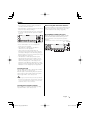
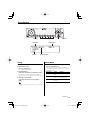
General features
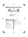
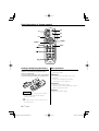
ATT
ANG
VOL
Q/MENU
SRC
Control knob
FM1-6ch
98.1
12:34
01-Jan-05 Sat
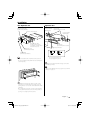
Power
Turning ON the Power
Turn the vehicle ignition ON.
The control panel appears.
Turing OFF the Power
Turn the vehicle ignition OFF or press the
[SRC] button for at least 1 second.
The control panel is hidden.
• Do not apply force to the control panel during this
operation. It can cause damage.
Hiding the Control Panel
Prevents tampering with the unit while your car is
being serviced etc.
Hiding the control panel
Press the [SRC] button for at least 1 second.
When the time set in <OFF Wait Time Setting>
(page 31) lapses, the panel is hidden and the
power turns OFF.
Showing the control panel
Press the lower left part of the panel.
The panel opens to enable the operation.
English |
B64-3147-00_K_English.indd 9
9
05.5.9 2:32:22 PM
General features
Selecting the Source
Press the [SRC] button.
Source required
SIRIUS tuner (Optional accessory)
Tuner or HD Radio (Optional accessory)
CD
External disc (Optional accessory)
Auxiliary input
Auxiliary input (Optional accessory)
Standby (Illumination only mode)
Display
"SIRIUS"
"TUNER" or "HD RADIO"
"Compact Disc"
"CD Changer"
"AUX"
"AUX EXT"
"STANDBY"
Sound setting
User memory
Rock
Pops
Easy
Top 40
Jazz
Natural
Display
"User"
"Rock"
"Pops"
"Easy"
"Top 40"
"Jazz"
"Natural"
• User memory: The values set on the <Audio Control>
(page 11).
• Change each setting value with the <Speaker
Setting> (page 10).
First, select the speaker type with the Speaker setting.
Volume
Increasing Volume
Turn the [VOL] knob clockwise.
Speaker Setting
Decreasing Volume
Turn the [VOL] knob counterclockwise.
Fine-tuning so that the System Q value is optimal
when setting the speaker type.
1 Enter Standby
Attenuator
Turning the volume down quickly.
Press the [ATT] button.
Each time you press the button is pressed, the
Attenuator turns ON and OFF.
When the Attenuator is ON, "ATT ON" is
displayed.
System Q
Selecting the best sound setting preset for
different types of music.
1 Select the source to set
Press the [SRC] button.
Press the [SRC] button.
Select the "STANDBY" display.
2 Enter Speaker Setting mode
Press the [VOL] knob.
3 Select the Speaker type
Turn the [VOL] knob.
Each time you turn the knob, the setting
alternates between the settings shown in the
table below.
Speaker type
OFF
For 5 & 4 in. speaker
For 6 & 6x9 in. speaker
For the OEM speaker
Display
"Speaker
"Speaker
"Speaker
"Speaker
OFF"
5/4inch"
6x9/6inch"
O.E.M."
4 Exit Speaker Setting mode
Press the [VOL] knob.
2 Select the Sound type
Press the [Q] button.
Each time you press the button is pressed, the
sound setting alternates.
10 |
English
B64-3147-00_K_English.indd 10
05.5.9 2:32:23 PM
Audio Control
1 Select the source to adjust
Press the [SRC] button.
2 Enter Audio Control mode
Press the [VOL] knob.
3 Select the Basic Audio item to adjust
Press the [VOL] knob.
Each time you press the knob, the item to be
adjusted alternates between the items shown in
the table below.
4 Adjust the Basic Audio item
Turn the [VOL] knob.
Adjustment Item Display
"R-Volume"
Rear Volume *1
Subwoofer level*2,3 "SW_Level"
Bass level*4
"Bass Level"
Middle level*4
"Middle Level"
Treble level*4
"Treble Level"
Balance
"Balance"
Fader*3
"Fader"
Exit Audio Control mode
Range
0 — 35
–15 — +15
–8 — +8
–8 — +8
–8 — +8
Left 15 — Right 15
Rear 15 — Front 15
• *1 You can control this item when "2Zone" of <Audio
Setup> (page 12) is set to "ON".
• *3 You can control this item when <Subwoofer
Output> (page 12) is set to "SW ON".
• *3 You can control this item when "2Zone" of <Audio
Setup> (page 12) is set to "OFF".
• *4 You can adjust these items in detail by the following
methods.
• *4 Source tone memory: Puts the set up value in the
memory per source. (Detail Audio item is included)
3 Select the Detail Audio item to adjust
Press the [VOL] knob.
Each time you press the knob, the item to be
adjusted alternates between the items shown
in the table below.
4 Adjust the Detail Audio item
Turn the [VOL] knob.
Bass level
Adjustment Item
Display
Range
Bass Center Frequency "Bass Freq" 40/50/60/70/80/100/
120/150 Hz
Bass Q Factor
"Bass Q"
1.00/1.25/1.50/2.00
Bass Extend
"Bass EXT" ON/OFF
Middle level
Adjustment Item
Display
Range
Middle Center Frequency "Middle Freq" 0.5/1.0/1.5/2.0 kHz
Middle Q Factor
"Middle Q" 1.0/2.0
Treble level
Adjustment Item
Display
Range
Treble Center Frequency "Treble Freq" 10.0/12.5/15.0/17.5 kHz
5 Exit the Detail Audio Control mode
Press the [VOL] knob for at least 1 second.
• When you set the Bass Extend to ON, low frequency
response is extended by 20%.
• You can exit the Audio Control mode at anytime by
pressing any button except for [VOL], [ANG] and [ATT]
buttons.
5 Exit Audio Control mode
Press any button.
Press a button other than the [VOL] knob and
[ATT]/ [ANG] button.
Adjust the detail of Audio Control
1 Select the Audio item to adjust
By referring to the step 1 — 3 above, select the
desired item to be set in detail from the items
marked with *4.
2 Enter Detail adjustment mode of Audio
Control
Press the [VOL] knob for at least 1 second.
English |
B64-3147-00_K_English.indd 11
11
05.5.9 2:32:23 PM
General features
Audio Setup
Setting the Sound system, such as Cross over
Network.
1 Select the source to adjust
• You can use the Dual Zone System with the Auxiliary
input sources listed below.
- Internal auxiliary input
5 Exit Audio Setup mode
Press [VOL] knob for at least 1 second.
Press the [SRC] button.
2 Enter Audio Setup mode
Press the [VOL] knob for at least 1 second.
3 Select the Audio Setup item to adjust
Press the [VOL] knob.
Each time you press the knob, the item to be
adjusted alternates between the items shown in
the table below.
4 Setup the Audio item
Turn the [VOL] knob.
Adjustment Item Display
Front High Pass Filter*2 "HPF-F"
Rear High Pass Filter*2 "HPF-R"
Low Pass Filter*1,2
"LPF"
1,2,3
Subwoofer Phase*
Volume offset
Loudness
Dual Zone System
"SW Phase"
"VOL Offset"
"Loudness"
"2Zone"
Range
Through/40/60/80/100/
120/150/180/220 Hz
Through/40/60/80/100/
120/150/180/220 Hz
50/60/80/100/120/
Through Hz
Normal (0°)/ Reverse (180°)
–8 — ±0
ON/OFF
ON/OFF
Subwoofer Output
Turning the Subwoofer output ON or OFF.
Hold down on [AM] of the Control knob for at
least 1 second.
Each time you press the button, Subwoofer
output switches ON and OFF.
When it is ON, "SW ON" is displayed.
• You can control this function when "2Zone" of <Audio
Setup> (page 12) is set to "OFF".
Display Setting
Changing the display mode.
1 Enter display Control mode
Press the Control knob for at least 1 second.
"Display Control" is displayed.
2 Select the Display mode
• Volume offset: Sets each source’s volume as a
difference from the basic volume.
• Loudness: Compensates for low and high tones
during low volume.
• *1 You can control this item when <Subwoofer
Output> (page 12) is set to "SW ON".
• *2 You can control this item when "2Zone" of <Audio
Setup> (page 12) is set to "OFF".
• *3 You can control this item when Low Pass Filter is not
set to Through.
• Dual Zone System
Main source and sub source (Auxiliary input) output
Front channel and Rear channel separately.
- Set up the channel of sub source by <Dual Zone
System Setting> (page 31).
- Select Main source by [SRC] button.
- Adjust the volume of Front channel by [VOL] knob.
- Adjust the volume of Rear channel by <Audio
Control> (page 11).
- The Audio Control has no effect on sub source.
12 |
Press the Control knob.
Each time you press the knob, the display
alternates between the display modes shown in
the table below.
Display Mode
"Display Type A"
Display
5
"Display Type B"
4
5
"Display Type C"
1
2
3
English
B64-3147-00_K_English.indd 12
05.5.9 2:32:24 PM
1 Upper text display part
2 Middle text display part
3 Lower text display part
4 Text display part
5 Graphic display part
• You can display the information that will be shown
in the Upper text display part, the Lower text display
part or the Level meter display part according to the
setting of Display mode. Refer to the following pages
for how to select the mode.
Display Type
Upper 1
Middle 2
Lower 3
Text 4
Graphic 5
A
B
—
—
—
—
—
—
—
C
page 15
page 15
page 15
page 14
page 18
—
—
page 18
3 Exit Display Control mode
Press the Control knob for at least 1 second.
English |
B64-3147-00_K_English.indd 13
13
05.5.9 2:32:25 PM
General features
Display Type B
In Auxiliary input source
Text Selection for Display
Selecting the text display.
1 Enter display control mode
Press the Control knob for at least 1 second.
"Display Control" is displayed.
2 Select the display Type
Press the Control knob.
Select the "Display Type B" display.
3 Select the text display part
Push the Control knob towards [FM] or [AM].
The selected text display part blinks.
4 Push the Control knob towards [4] or
[¢].
Each time you push the knob, the display
alternates between the Information displays
shown in the tables below.
Display
"BAND+ch+SNPS"*
"BAND+ch+FREQ"
"Clock"
"Date"
In CD & External disc source
Information
Disc title
Track title
Track number & Play time
Disc name
Clock
Date
14 |
In SIRIUS tuner source
Information
Channel Name
Song Title
Artist Name
Composer name
Category Name
Label Name
Comment
Band & Channel Number
Clock
Date
Display
"Channel Name"
"Song Title"
"Artist Name"
"Composer Name"
"Category Name"
"Label Name"
"Comment"
"Channel Number"
"Clock"
"Date"
Information
Station name
Title
Frequency
Clock
Date
Display
"Station Name"*
"Title"*
"Frequency"
"Clock"
"Date"
In Standby
Display
"Disc Title"*
"Track Title"*
"P-Time"
"DNPS"
"Clock"
"Date"
In Audio file source
Information
Song title & Artist name
Album name & Artist name
Folder name
File name
Play time & File number
Clock
Date
Display
"SRC Name"
"Clock"
"Date"
In HD Radio source
In Tuner source
Information
Station name
Frequency
Clock
Date
Information
Auxiliary input name
Clock
Date
Display
"Title/Artist"*
"Album/Artist"*
"Folder Name"
"File Name"
"P-Time"
"Clock"
"Date"
Information
Standby
Clock
Date
Display
"SRC Name"
"Clock"
"Date"
• * If the contents of the information cannot be
displayed, Play time or Frequency is displayed.
• If the contents of the information for the SIRIUS
tuner source cannot be displayed, channel number is
displayed.
• When LX-AMP is connected, the item setup by the
Display mode of LX-AMP is displayed.
• Track number at Audio file displays the last 3 digits
when the track number exceeds 1000 songs.
5 Exit Display control mode
Press the Control knob for at least 1 second.
English
B64-3147-00_K_English.indd 14
05.5.9 2:32:25 PM
Display Type C
Text Display Switching
Changing the text display.
1 Enter display control mode
Press the Control knob for at least 1 second.
"Display Control" is displayed.
2 Select the display Type
Press the Control knob.
Select the "Display Type C" display.
3 Select the text display part
Push the Control knob towards [FM] or [AM].
The selected text display part blinks.
Select the text
Push the Control knob towards [4] or
[¢].
Refer to the table described later for setting
items.
4 Exit Display Control mode
Press the Control knob for at least 1 second.
• Same information cannot be displayed in Upper text
display part, Middle text display part and Lower text
display part. However, the blank display is able to have
multiple selections.
• If the contents of the information for the SIRIUS
tuner source cannot be displayed, channel number is
displayed.
• When LX-AMP is connected, the item setup by the
Display mode of LX-AMP is displayed.
• Track number at Audio file displays the last 3 digits
when the track number exceeds 1000 songs.
English |
B64-3147-00_K_English.indd 15
15
05.5.9 2:32:25 PM
General features
The text display in the Upper text display
part
In Tuner source
Information
Station name
Frequency
Spectrum Analyzer & Clock
Date
Display
"BAND+ch+SNPS"*
"BAND+ch+FREQ"
"Speana/Clock"
"Date"
In CD & External disc source
Information
Disc title
Track title
Track number & Play time
Disc name
Spectrum Analyzer & Clock
Date
Display
"Disc Title"*
"Track Title"*
"P-Time"
"DNPS"
"Speana/Clock"
"Date"
In Audio file source
Information
Song title & Artist name
Album name & Artist name
Folder name
File name
Play time & File number
Spectrum Analyzer & Clock
Date
Display
"Title/Artist"*
"Album/Artist"*
"Folder Name"
"File Name"
"P-Time"
"Speana/Clock"
"Date"
In SIRIUS tuner source
Information
Channel Name
Song Title
Artist Name
Composer name
Category Name
Label Name
Comment
Band & Channel Number
Spectrum Analyzer & Clock
Date
Display
"Channel Name"
"Song Title"
"Artist Name"
"Composer Name"
"Category Name"
"Label Name"
"Comment"
"Channel Number"
"Speana/Clock"
"Date"
• * If the contents of the information cannot be
displayed, Play time or Frequency is displayed.
The text display in the Middle text display
part
In Tuner source
Information
Spectrum Analyzer & Clock
Date
Blank
Display
"Speana/Clock"
"Date"
"Blank"
In CD & External disc source
In Standby
Information
Standby
Clock
Date
Display
"SRC Name"
"Clock"
"Date"
In Auxiliary input source
Information
Auxiliary input name
Spectrum Analyzer & Clock
Date
Display
"SRC Name"
"Speana/Clock"
"Date"
In HD Radio source
Information
Station name
Title
Frequency
Spectrum Analyzer & Clock
Date
16 |
Display
"Station Name"*
"Title"*
"Frequency"
"Speana/Clock"
"Date"
Information
Spectrum Analyzer & Clock
Date
Blank
Disc title
Track title
Disc name
Display
"Speana/Clock"
"Date"
"Blank"
"Disc Title"*
"Track Title"*
"DNPS"
In Audio file source
Information
Spectrum Analyzer & Clock
Date
Blank
Song title & Artist name
Album name & Artist name
Folder name
File name
Display
"Speana/Clock"
"Date"
"Blank"
"Title/Artist"*
"Album/Artist"*
"Folder Name"
"File Name"
English
B64-3147-00_K_English.indd 16
05.5.9 2:32:26 PM
In Standby
Information
Clock
Date
Blank
Display
"Clock"
"Date"
"Blank"
In Auxiliary input source
Information
Spectrum Analyzer & Clock
Date
Blank
Display
"Speana/Clock"
"Date"
"Blank"
In HD Radio source
Information
Spectrum Analyzer & Clock
Date
Blank
Title
Display
"Speana/Clock"
"Date"
"Blank"
"Title"*
In SIRIUS tuner source
Information
Spectrum Analyzer & Clock
Date
Blank
Channel Name
Song Title
Artist Name
Composer name
Category Name
Label
Comment
Display
"Speana/Clock"
"Date"
"Blank"
"Channel Name"
"Song Title"
"Artist Name"
"Composer Name"
"Category Name"
"Label Name"
"Comment"
• * If the contents of the information cannot be
displayed, Kenwood Logo is displayed. However, in
HD Radio source, the display becomes blank.
English |
B64-3147-00_K_English.indd 17
17
05.5.9 2:32:26 PM
General features
The text display in the Lower text display
part
In Tuner source
Information
Indicator
Spectrum Analyzer & Clock
Date
Blank
Display
"Indicator"
"Speana/Clock"
"Date"
"Blank"
In CD & External disc source
Information
Indicator
Spectrum Analyzer & Clock
Date
Blank
Disc title
Track title
Disc name
Display
"Indicator"
"Speana/Clock"
"Date"
"Blank"
"Disc Title"*
"Track Title"*
"DNPS"
In Audio file source
Information
Indicator
Spectrum Analyzer & Clock
Date
Blank
Song title & Artist name
Album name & Artist name
Folder name
File name
Display
"Indicator"
"Speana/Clock"
"Date"
"Blank"
"Title/Artist"*
"Album/Artist"*
"Folder Name"
"File Name"
Display
"Indicator"
"Clock"
"Date"
"Blank"
In Auxiliary input source
Information
Indicator
Spectrum Analyzer & Clock
Date
Blank
Information
Indicator
Spectrum Analyzer & Clock
Date
Blank
Title
Display
"Indicator"
"Speana/Clock"
"Date"
"Blank"
"Title"*
In SIRIUS tuner source
Information
Indicator
Spectrum Analyzer & Clock
Date
Blank
Channel Name
Song Title
Artist Name
Composer name
Category Name
Label
Comment
Display
"Indicator"
"Speana/Clock"
"Date"
"Blank"
"Channel Name"
"Song Title"
"Artist Name"
"Composer Name"
"Category Name"
"Label Name"
"Comment"
• * If the contents of the information cannot be
displayed, indicator is displayed. However, In HD
Radio source, a display becomes a blank display.
Display Type A/ Display Type B
Graphic part/ Spectrum Analyzer
Display Switching
In Standby
Information
Indicator
Clock
Date
Blank
In HD Radio source
Display
"Indicator"
"Speana/Clock"
"Date"
"Blank"
Changing the graphic Display/ Spectrum analyzer
display.
1 Enter display control mode
Press the Control knob for at least 1 second.
"Display Control" is displayed.
2 Select the display Type
Press the Control knob.
Select the "Display Type A"/ "Display Type B"
display.
3 Select the graphic/ spectrum analyzer
display ("Display Type B" only)
Push the Control knob towards [FM] or [AM].
The blinking text display part stops.
18 |
English
B64-3147-00_K_English.indd 18
05.5.9 2:32:27 PM
4 Select the graphic/ spectrum analyzer
display part display
Push the Control knob towards [4] or
[¢].
Each time you push the knob, the display
alternates between the display names shown in
the table below.
Graphic display/ Spectrum Analyzer display
Wallpaper 1 – 5
Spectrum analyzer 1 – 5
5 Exit Display control mode
Press the Control knob for at least 1 second.
7 Select the characters
Push the Control knob towards [FM] or [AM].
• Enter characters by using a remote control with
numbers buttons.
Example: If you are entering "DANCE".
Character
"D"
"A"
"N"
"C"
"E"
Button
[3]
[2]
[6]
[2]
[3]
Times pressed
1
1
2
3
2
8 Repeat steps 5 through 7 and enter the name.
9 Exit Menu mode
Station/Disc Naming (SNPS/DNPS)
Attaching a title to a Station or CD.
1 Receive/play the station/disc you want to
attach a title to
• A title cannot be attached to MD or Audio file media.
2 Enter Menu mode
Press the [MENU] button for at least 1 second.
"Menu" is displayed.
Press the [MENU] button.
• When operation stops for 10 seconds the name at
that time is registered, and Name Set mode closes.
• Memory numbers
- FM/AM: 30 stations
- Internal CD player: 10 discs
- External CD changer/ player: Varies according to the
CD changer/ player. Refer to the CD changer/ player
manual.
• Change the title of station/CD by the same operation
used to name it.
3 Select Name set mode
Push the Control knob towards [FM] or [AM].
Select the "Name Set" display.
4 Enter Name set mode
Press the Control knob for at least 1 second.
Faceplate Angle Adjustment
Press the [ANG] button for at least 1 second.
5 Move the cursor to the enter character
position
Push the Control knob towards [4] or
[¢].
• Do not apply excessive force to the faceplate. It can
cause damage.
6 Select the character type
Press the Control knob.
Each time you press the knob, the character type
alternates between the types shown in the table
below.
Character type
Alphabet upper case
Alphabet lower case
Numbers and symbols
Special characters (Accent characters)
English |
B64-3147-00_K_English.indd 19
19
05.5.9 2:32:27 PM
General features
Theft Deterrent Faceplate
TEL Mute
The faceplate of the unit can be detached and
taken with you, helping to deter theft.
The audio system automatically mutes when a
call comes in.
Removing the Faceplate
When a call comes in
"CALL" is displayed.
The audio system pauses.
1 Turn the ignition OFF or press the [SRC]
button for at least 1 second.
The power turns OFF and the faceplate slides
open.
2 Holding the center part of the faceplate pull
it out.
Listening to the audio during a call
Press the [SRC] button.
The "CALL" display disappears and the audio
system comes back ON.
When the call ends
Hang up the phone.
The "CALL" display disappears and the audio
system comes back ON.
• When the faceplate is kept remove open, according
to the <OFF Wait Time Setting> (page 31) setting, the
faceplate is hidden and the power turns OFF.
• The faceplate is a precision piece of equipment and
can be damaged by shocks or jolts. For that reason,
keep the faceplate in its special storage case while
detached.
• Do not expose the faceplate or its storage case to
direct sunlight or excessive heat or humidity. Also
avoid places with too much dust or the possibility of
water splashing.
Reattaching the Faceplate
1 Set the left side of the faceplate in the
faceplate bracket.
2 Press the right side of the faceplate until it
locks.
• Use the enclosed or dedicated faceplate. Using a
faceplate other than the specified one may cause your
unit to malfunction.
20 |
English
B64-3147-00_K_English.indd 20
05.5.9 2:32:28 PM
Tuner features
AUTO/AME
1—6
SRC
Band display
Frequency display
FM1-6ch
SNPS
ST
98.1
ST indicator
Control knob
Preset station number
Tuning
Tuning Mode
Selecting the station.
Choose the tuning mode.
1 Select tuner source
Press the [SRC] button.
Select the "TUNER" display.
2 Select the band
Push the Control knob towards [FM] or [AM].
Each time you push the knob toward [FM], it
switches between the FM1, FM2, and FM3 bands.
3 Tune up or down band
Push the Control knob towards [4] or
[¢].
Press the [AUTO] button.
Each time you press the button, the Tuning
mode alternates between the modes shown in
the table below.
Tuning mode
Display
Operation
Auto seek
"Seek Mode: Automatic search for a station.
Auto1"
Preset station seek "Seek Mode: Search in order of the stations
Auto2"
in the Preset memory.
Manual
"Seek Mode: Normal manual tuning control.
Manual"
• During reception of stereo stations the "ST" indicator
is ON.
English |
B64-3147-00_K_English.indd 21
21
05.5.9 2:32:28 PM
Tuner features
Function of remote control
Direct Access Tuning
Auto Memory Entry
Entering the frequency and tuning.
Putting stations with good reception in the
memory automatically.
1 Select the band
1 Select the band for Auto Memory Entry
Press the [FM] or [AM] button.
2 Enter Direct Access Tuning mode
Press the [DIRECT] button on the remote
control.
"– – – –" is displayed.
Push the Control knob towards [FM] or [AM].
2 Open Auto Memory Entry
Press the [AME] button for at least 2 seconds.
When 6 stations that can be received are put in
the memory Auto Memory Entry closes.
3 Enter the frequency
Press the number buttons on the remote
control.
Example:
Desired frequency
Press button
92.1 MHz (FM)
[0], [9], [2], [1]
810 kHz (AM)
[0], [8], [1], [0]
Cancelling Direct Access Tuning
Press the [DIRECT] button on the remote
control.
Preset Tuning
Recalling the stations in the memory.
1 Select the band
Push the Control knob towards [FM] or [AM].
2 Recall the station
Press the desired [1] — [6] button.
Station Preset Memory
Putting a station in the memory.
1 Select the band
Push the Control knob towards [FM] or [AM].
2 Select the frequency to put in the memory
Push the Control knob towards [4] or
[¢].
3 Put the frequency in the memory
Press the desired [1] — [6] button for at least
2 seconds.
The preset number display blinks 1 time.
On each band, 1 station can be put in the
memory on each [1] — [6] button.
22 |
English
B64-3147-00_K_English.indd 22
05.5.9 2:32:29 PM
CD/Audio file/External disc control features
0
S.MODE
RDM/3/
F.SEL
SCAN D.RDM REP
M.RDM
Track number
SRC
Control knob
Track time
MP3 T-01
0:12
Title/Artist
IN
IN indicator
Playing CD & Audio file
When there is no disc inserted
1 Open the panel
Press the [0] button.
2 Insert a disc.
• When the faceplate slides open, it might interfere
with the shift lever or other vehicle function. If this
happens, pay attention to safety and move the shift
lever or take an appropriate action to remove the
obstacle, then operate the unit.
• Insert the disc horizontal to the slot. If you insert the
Disc as you push down on the Disc, it may scratch the
Disc.
When a disc is inserted
Press the [SRC] button.
Select the "Compact Disc" display.
Pause and play
Press the Control knob.
Each time you press the knob, the audio pauses
or plays.
Eject the disc
1 Eject the disc
Press the [0] button.
2 Return the panel to the original position
Press the [0] button.
• The sound will be temporarily muted while the
faceplate is moving.
• You can cancel the announcement when selecting
the folder by <Voice Index> (page 34) during the play
of the ACDrive.
• When a disc is inserted the "IN" indicator is ON.
English |
B64-3147-00_K_English.indd 23
23
05.5.9 2:32:29 PM
CD/Audio file/External disc control features
Playing External Disc
Playing discs set in the optional accessory disc
player connected to this unit.
Press the [SRC] button.
Select the display for the disc player you want.
Display examples:
Display
"CD Changer"
"MD Changer"
Disc player
CD changer
MD changer
Pause and play
Press the Control knob.
Each time you press the knob, the audio pauses
or plays.
Function of disc changer/ Audio file
Disc Search/Folder Search
Selecting the disc set in the Disc changer or the
folder recorded on the Audio file media.
Push the Control knob towards [FM] or [AM].
Function of remote control
Direct Track/File Search
Doing Track/File Search by entering the track/file
number.
1 Enter the track/file number
Press the number buttons on the remote
control.
• The functions that can be used and the information
that can be displayed will differ depending on the
external disc players being connected.
• You can select Direct File Search up to 999.
2 Do Track/File Search
Press the [4] or [¢] button.
Fast Forwarding and Reversing
Fast Forwarding
Hold down toward [¢] with the Control
knob.
Release your finger to play the disc at that point.
Reversing
Hold down toward [4] with the Control
knob.
Release your finger to play the disc at that point.
• There is no sound while the Audio file is being
searched.
Track/File Search
Searching for a song on the disc or in the Audio
file folder.
Cancelling Direct Track/File Search
Press the [38] button.
Function of disc changers with remote control
Direct Disc Search
Doing Disc Search by entering the disc number.
1 Enter the disc number
Press the number buttons on the remote
control.
2 Do Disc Search
Press the [+] or [–] button.
Cancelling Direct Disc Search
Press the [38] button.
• Input "0" to select disc 10.
Push the Control knob towards [4] or
[¢].
24 |
English
B64-3147-00_K_English.indd 24
05.5.9 2:32:29 PM
Track/File/Disc/Folder Repeat
Replaying the song, disc in the Disc changer or
Audio file folder you are listening to.
Press the [REP] button.
Each time you press the button, the Repeat Play
alternates between the modes shown in the
tables below.
In CD & External disc source
Repeat play
Track Repeat
Disc Repeat (In Disc Changer)
OFF
Display
"Repeat ON"/ "Track Repeat ON"
"Disc Repeat ON"
"Repeat OFF"
Function of disc changer
Magazine Random Play
Play the songs on all the discs in the disc changer
in random order.
Press the [M.RDM] button.
Each time you press the button, the Magazine
Random Play turns ON or OFF.
When the Magazine Random mode is ON,
"Magazine RDM ON" is displayed.
• When you push the Control knob toward [¢], the
next random song starts.
In Audio file
Repeat play
File Repeat
Folder Repeat
OFF
Display
"File Repeat ON"
"Folder Repeat ON"
"Repeat OFF"
Scan Play
Playing the first part of each song on the disc
or Audio file folder you are listening to and
searching for the song you want to hear.
1 Start Scan Play
Press the [SCAN] button.
"Scan ON" is displayed.
Function of Audio file
Disc Random Play
Playing randomly from all of the Audio files
recorded in the disc.
Press the [RDM] button for at least 1 second.
When the random mode is ON, "Disc Random
ON" is displayed.
Cancelling the Disc Random Play
Press the [RDM] button.
• When you push the Control knob toward [¢], the
next random song starts.
2 Release the button when the song you want
to hear is played
Press the [SCAN] button.
Random Play
Play all the songs on the disc or Audio file folder
in random order.
Press the [RDM] button.
Each time you press the button, Random Play
turns ON or OFF.
When the Random mode is ON, "Random ON" is
displayed.
• When you push the Control knob toward [¢], the
next random song starts.
English |
B64-3147-00_K_English.indd 25
25
05.5.9 2:32:30 PM
CD/Audio file/External disc control features
Function of Audio file
Function of ACDrive disc
Folder Select
Switching the Play mode
Quickly selecting the folder you want to hear.
Arrange the playing orders of the songs by
categories.
1 Enter Folder Select mode
Press the [F.SEL] button.
"Select Mode" is displayed.
During Select mode the folder information is
displayed as shown below.
Folder number display
Displays the number in the folder belonging to
the currently selected folder.
55
55555555
5
Select F02
Folder Name
55555555
Folder name display
Displays the current folder name.
• The Folder number display does not function when
<Disc Random Play> (page 25) is ON.
2 Select the folder level*
Push the Control knob towards [FM] or [AM].
With the [FM] of the Control knob, you move
1 level down and with the [AM] of the Control
knob, 1 level up.
Selecting a folder in the same level
Push the Control knob towards [4] or
[¢].
With the [4] of the Control knob, you move
to the previous folder, and with the [¢] of the
Control knob, to the next folder.
Returning to the top level*
Press the [3] button.
• * You can operate this function when <Switching the
Play mode> (page 26) is set to "Folder Mode" while
playing ACDrive disc.
3 Decide the folder to play
Press the Control knob.
The Folder Select mode releases, and the Audio
file in the folder being displayed plays.
Press the [S.MODE] button.
Each time you press the button, the Play mode
alternates between the modes shown on the
table below.
Play mode
Category which is to be arranged
"PlayList Mode" Play list order.
"Genre Mode" By genre.
"Artist Mode"
By artist.
"Album Mode" By album.
"Folder Mode" By the folder recorded in Disc.
• The category information of each song is the data
registered in Media Manager when ACDrive disc is
being generated.
• You can cancel the announcement made when the
mode is changed by <Voice Index> (page 34).
• You can select the advancement of the Play mode
information by [AM] and [FM] keys.
Function of ACDrive disc
Letter Seek
You can search for the song, you want to play, by
selecting the initial of Genre name, Artist name,
or Album name.
1 Enter the Letter Seek mode
Press the [S.MODE] button for at least 1
second.
• This operation does not function when <Disc Random
Play> (page 25) is ON.
• This function is available only when the Play mode is
set Genre, Artist, or Album.
Cancelling the Letter Seek
Press the [S.MODE] button.
Cancelling the Folder Select mode
Press the [F.SEL] button.
26 |
English
B64-3147-00_K_English.indd 26
05.5.9 2:32:30 PM
2 Start the Letter Seek
Push the Control knob towards [4] or
[¢].
The initial of Genre name, Artist name, or Album
name is displayed and announced in order.
• The announcement of the initial can be canceled by
<Voice Index> (page34).
• When you push the Control knob to the reverse [4]
or [¢] during Letter Seek, the initial is displayed
and announced in the reversed order.
• Once Letter Seek starts, it cannot be cancelled.
3 Select the song to play
Press the Control knob when the initial of
the song you are searching is displayed and
announced.
The selected initial group plays.
Text/Title Scroll
Scrolling the displayed CD text, Audio file text, or
MD title.
Push the Control knob toward [FM] for at
least 1 second.
English |
B64-3147-00_K_English.indd 27
27
05.5.9 2:32:31 PM
HD Radio control features
AUTO/AME
1—6
Band display
SRC
Control knob
Frequency display
HF1-6ch
98.1
Station Name
Title
Preset station number
Tuning
• When you connect an HD Radio, Tuner features of
the unit are disabled and changed to HD Radio tuner
features. A portion of the setting methods including
the Tuning Mode will change.
• With the HD Radio tuner, you can use the similar
functions to <Station Preset Memory>, <Auto
Memory Entry>, and <Preset Tuning> of Tuner
features. Refer to Tuner features for how to use the
functions.
Selecting the station.
1 Select HD Radio source
Press the [SRC] button.
Select the "HD Radio" display.
2 Select the HD FM band
Push the Control knob toward [FM].
Each time you push the knob to [FM], the band
alternates between the HF1, HF2, and HF3 bands.
Select the HD AM band
Push the Control knob toward [AM].
3 Tune up or down band
Push the Control knob towards [4] or
[¢].
28 |
English
B64-3147-00_K_English.indd 28
05.5.9 2:32:31 PM
Menu system
MENU
SRC
Control knob
Clock Adjust
Beep:ON
Security
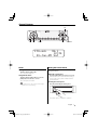
Menu System
Setting beep sound during operation, etc.
functions.
The Menu system basic operation method is
explained here. The reference for the Menu items
and their setting content is after this operation
explanation.
1 Enter Menu mode
Press the [MENU] button for at least 1 second.
"Menu" is displayed.
2 Select the menu item
Push the Control knob towards [FM] or [AM].
Example: When you want to set the beep sound
select the "Beep" display.
You can continue by returning to step 2 and
setting other items.
4 Exit Menu mode
Press the [MENU] button.
• When other items those applicable to the basic
operation method above are displayed, their setting
content chart is entered. (Normally the setting listed at
the top of the chart is the original setting.)
Also, the explanation for items that are not applicable
(<Manual Clock Adjustment> etc.) are entered step
by step.
• Three menu items appear on the display. The menu
item displayed at the center is the one you can adjust.
3 Set the menu item
Push the Control knob towards [4] or
[¢].
Example: When you select "Beep", each time you
push the knob it alternates between
"Beep:ON" or "Beep:OFF". Select 1 of
them as the setting.
English |
B64-3147-00_K_English.indd 29
29
05.5.9 2:32:32 PM
Menu system
In Standby mode
Security Code
Because authorization by the Security Code is
required when the audio unit is removed from
the vehicle, personalizing this unit by using the
Security Code is helpful in preventing theft.
• Setup Security Code when the <Demonstration mode
Setting> (page 35) is set as OFF.
• When you activate the Security Code function, the code
cannot be changed and the function cannot be released.
Note, you can set the Security Code with a 4 digit
number of your choice.
1 Enter Standby
Press the [SRC] button.
Select the "STANDBY" display.
2 Enter Menu mode
Press the Reset button when the audio unit is
removed from the battery power source
1 Turn the power ON.
2 Do the step 4 through 7 operation, and enter
the Security Code.
"Approved" is displayed.
You can being using the unit.
In Standby mode
Touch Sensor Tone
Setting the operation check sound (beep sound)
ON/OFF.
Display
"Beep:ON"
"Beep:OFF"
Setting
Beep is heard.
Beep canceled.
Press the [MENU] button for at least 1 second.
When "Menu" is displayed, "Security" is also
displayed.
3 Enter Security Code mode
Press the Control knob for at least 1 second.
When "Enter" is displayed, "CODE" is also
displayed.
4 Select the digits to enter
Push the Control knob towards [4] or
[¢].
5 Select the Security Code numbers
Push the Control knob towards [FM] or [AM].
6 Repeat steps 4 and 5, and complete the
Security Code.
7 Confirm the Security Code
Press the Control knob for at least 3 seconds.
When "Re-Enter" is displayed, "CODE" is also
displayed.
8 Do the step 4 through 7 operation, and
In Standby mode
Manual Clock Adjustment
1 Select Clock Adjustment mode
Push the Control knob towards [FM] or [AM].
Select the "Clock Adjust" display.
2 Enter Clock Adjust mode
Press the Control knob for at least 1 second.
The clock display blinks.
3 Adjust the hours
Push the Control knob towards [FM] or [AM].
Adjust the minutes
Push the Control knob towards [4] or
[¢].
4 Exit Clock adjustment mode
Press the [MENU] button.
reenter the Security Code.
"Approved" is displayed.
The Security Code function activates.
• If you enter the wrong Code in steps 4 through 6,
repeat from step 4.
30 |
English
B64-3147-00_K_English.indd 30
05.5.9 2:32:32 PM
In Standby mode
In Standby mode
Date Adjustment
OFF Wait Time Setting
1 Select Date Adjust mode
Setting the time until the faceplate hiding
operation starts after the power is turned OFF.
You can only remove the faceplate during the set
time period.
Press the Control knob for at least 1 second.
The date display blinks.
3 Selecting the item (day, month, or year) to
adjust
Push the Control knob towards [4] or
[¢].
The items that are blinking are items that you
can adjust.
4 Adjust each item
Push the Control knob towards [FM] or [AM].
5 Repeat step 3 and 4 operation and adjust the
date.
6 Exit Date adjustment mode
Press the [MENU] button.
Display and Setting
"Off Wait:0sec"
…
2 Enter Date Adjust mode
"Off Wait:3sec" (Original setting)
…
Push the knob towards [FM] or [AM].
Select the "Date Adjust" display.
"Off Wait:25sec"
In Standby mode
Built-in Amp Setting
Controlling the built-in amplifier.
Turning OFF this control enhances the preout
quality.
Display
"AMP:ON"
"AMP:OFF"
Setting
The built-in amplifier activates.
The built-in amplifier deactivates.
In Standby mode
Date Mode
Setting the date format.
Other than Standby mode/
When the Dual Zone System is ON
1 Select Date Mode
Dual Zone System Setting
Push the Control knob towards [FM] or [AM].
Select the "Date Mode" display.
2 Select the date format
Push the Control knob towards [4] or
[¢].
3 Exit Date mode
Push the Control knob towards [FM] or [AM].
Setting the Front channel and Rear channel
sound in the Dual Zone System.
Display
"Zone2:Rear"
"Zone2:Front"
Setting
Sub source (Auxiliary input source) is to be rear
channel.
Sub source (Auxiliary input source) is to be front
channel.
In Standby mode
Dimmer
Dimming this unit’s display automatically when
the vehicle light switch is turned ON.
Display
"Dimmer:ON"
"Dimmer:OFF"
Setting
The display dims.
The display doesn’t dim.
English |
B64-3147-00_K_English.indd 31
31
05.5.9 2:32:33 PM
Menu system
Other than Standby mode
B.M.S. (Bass Management System)
Adjust the bass boost level of the external
amplifier using the main unit.
4 Adjust the AMP Control item
Push the Control knob towards [4] or
[¢].
5 Exit AMP Control mode
Press the [MENU] button.
Display
"AMP Bass:Flat"
"AMP Bass:+6"
"AMP Bass:+12"
"AMP Bass:+18"
Setting
Bass boost level is flat.
Bass boost level is low (+6dB).
Bass boost level is mid (+12dB).
Bass boost level is high (+18dB).
• Refer to the catalog or instruction manual for power
amplifiers that can be controlled from this unit.
• For amplifiers, there are the models you can set from
Flat to +18 dB, and the models you can set from Flat
to +12 dB.
When an amplifier that can only be set to +12 is
connected to the unit, "AMP Bass:+18" will not work
correctly even if it is selected.
• You cannot use the LX AMP operation during standby
mode.
In FM reception
CRSC (Clean Reception System
Circuit)
Temporarily have reception alternate from
stereo to mono to reduce multi-path noise when
listening to the FM station.
Display
"CRSC:ON"
"CRSC:OFF"
Setting
The CRSC is ON.
The CRSC is OFF.
Other than Standby mode
B.M.S. Frequency Offset
Setting the central frequency, boosted by B.M.S.
Display
"AMP FREQ:Normal"
"AMP FREQ:Low"
• Strong electrical fields (such as from power lines) may
cause unstable sound quality when CRSC is turned
ON. In such a situation, turn it OFF.
Setting
Boost with the normal central frequency.
Drop the normal central frequency 20%.
In HD Radio mode
Receive mode Setting
When LX AMP unit connecting
AMP Control
You can control the LX AMP connected to the
unit.
1 Select AMP Control mode
Push the Control knob towards [FM] or [AM].
Select the "AMS Control" display.
2 Enter AMP Control mode
Press the Control knob for at least 1 second.
3 Select the AMP Control item for adjustment
Sets the receive mode.
1 Select the Receive mode
Push the Control knob towards [FM] or [AM].
Select the "Receive Mode" display.
2 Enter Receive mode
Press the Control knob for at least 1 second.
3 Set the Receive mode
Push the Control knob towards [FM] or [AM].
Each time you push the knob, the Receive mode
alternates between the modes shown in the
table below.
Push the Control knob towards [FM] or [AM].
• For the details on the AMP Control item, see the
Instruction manual attached to the LX AMP.
32 |
English
B64-3147-00_K_English.indd 32
05.5.9 2:32:33 PM
Receive mode
Auto mode
Digital
Analog
Display
"Auto"
"Digital"
"Analog"
Operation
Analog broadcasts and digital
broadcasts will be switched
automatically.
When both are being transmitted,
the digital broadcast will have
priority.
Digital broadcasts only.
Analog broadcasts only.
4 Exit Receive mode
Press the [MENU] button.
• Even if the Receive mode is set to "Auto", when the
Ball game mode program (non-delayed broadcast
program) is received, the Receive mode will
automatically switch to Analog broadcast only.
In SIRIUS tuner source
SIRIUS ID (ESN) display
Displaying the SIRIUS ID (Electronic Serial
Number)
Display
"ESN:************"
• Serial & SIRIUS ID (ESN)
It is important to retain the unit serial number and
the electronic SIRIUS Identification number for service
activation and potential service changes.
3 Select Auxiliary input display setting mode
Push the Control knob towards [FM] or [AM].
Select the "Name Set" display.
4 Enter Auxiliary input display setting mode
Press the Control knob for at least 1 second.
The presently selected Auxiliary input display is
displayed.
5 Select the Auxiliary input display
Push the Control knob towards [4] or
[¢].
Each time you press the button, the display
alternates as listed below.
• "AUX"/ "AUX EXT"
• "DVD"
• "PORTABLE"
• "GAME"
• "VIDEO"
• "TV"
6 Exit Auxiliary input display setting mode
Press the [MENU] button.
• When operation stops for 10 seconds, the name at
that time is registered, and the Auxiliary input display
setting mode closes.
• The Auxiliary Input Display can be set only when the
built-in auxiliary input or the auxiliary input of optional
KCA-S210A is used.
Text Scroll
Setting the displayed text scroll.
Auxiliary Input Display Setting &
Station/Disc Naming
Selecting the display when changing to Auxiliary
input source. For the Station/Disc Naming refer to
the <Station/Disc Naming (SNPS/DNPS)> (page
19).
1 Select Auxiliary input source
Press the [SRC] button.
Select the "AUX"/ "AUX EXT" display.
Display
"Scroll:Auto"
"Scroll:Manual"
Setting
Repeats scroll.
Scrolls when the display changes.
• The text scrolled is listed below.
- CD text
- Folder name/ File name/ Song title/ Artist name/
Album name
- MD title
- Text for the SIRIUS tuner source, HD Radio source,
including Channel name, etc.
2 Enter Menu mode
Press the [MENU] button for at least 1 second.
"Menu" is displayed.
English |
B64-3147-00_K_English.indd 33
33
05.5.9 2:32:34 PM
Menu system
In Standby mode
In CD mode
Built-in Auxiliary input Setting
Unique ID display
Set the Built-in Auxiliary Input function.
Displaying the serial number for each product.
Display
Setting
"Builtin AUX:OFF" When selecting the source there’s no Auxiliary
Input.
"Builtin AUX:ON" When selecting the source there’s Auxiliary Input.
1 Select the unique ID display mode
Push the Control knob towards [FM] or [AM].
Select the "ACD Unique ID" display.
2 Display the unique ID
Push the Control knob towards [4] or
[¢].
In Standby mode
CD Read Setting
When there is a problem with playing a CD with
special format, this setting plays the CD by force.
Display
"CD Read:1"
"CD Read:2"
Setting
Play CD and Audio file.
Play CD by force.
• Setting "CD Read:2" cannot play Audio file.
Some music CDs may not play even in the "CD
Read:2" mode.
Audio Preset Memory
Registering the value setup by Sound Control. The
memory cannot be erased by the Reset button.
1 Setup Sound Control
Refer to the following operations to setup the
Sound Control.
- <Audio Control> (page 11)
- <Audio Setup> (page 12)
2 Enter Menu mode
Press the [MENU] button for at least 1 second.
"Menu" is displayed.
Function of ACDrive disc
Voice Index
Setting the announcement during the play of
ACDrive disc.
Display
"Voice Index:ON"
"Voice Index:OFF"
Setting
Guide is announced.
Not be announced.
3 Select Audio Preset mode
Push the Control knob towards [FM] or [AM].
Select the "Audio Preset" display.
4 Enter Audio Preset mode
Press the Control knob for at least 1 second.
5 Select the Audio Preset Memory
Push the Control knob towards [FM] or [AM].
Select the "Memory" display.
6 Put the Audio Preset in the memory
In CD mode
ACDrive firmware version display
Displaying the firmware version with the ACDrive
function.
1 Select the firmware version display mode
Push the Control knob towards [FM] or [AM].
Select the "ACD F/W Version" display.
2 Display the ACDrive firmware version
Push the Control knob towards [4] or
[¢].
34 |
Press the Control knob for at least 2 seconds.
The "Memory" display blinks 1 time.
7 Exit Menu mode
Press the [MENU] button.
• Register 1 pair of Audio Preset Memory. You cannot
register by the source.
• When you press the Reset, all the sources will be the
setting value which is registered.
• The following items cannot be registered.
Volume, Balance, Fader, Loudness, Volume offset, Dual
Zone System, Rear Volume
English
B64-3147-00_K_English.indd 34
05.5.9 2:32:34 PM
Audio Preset Call
Recalling the sound setup registered by <Audio
Preset Memory> (page 34).
1 Select the source
Press the [SRC] button.
2 Enter Menu mode
Press the [MENU] button for at least 1 second.
"Menu" is displayed.
3 Select Audio Preset mode
Push the Control knob towards [FM] or [AM].
Select the "Audio Preset" display.
4 Enter Audio Preset mode
Press the Control knob for at least 1 second.
5 Select the Audio Preset Recall
Push the Control knob towards [FM] or [AM].
Select the "Recall" display.
6 Recall the Audio Preset
Press the Control knob for at least 2 seconds.
The "Recall" display blinks 1 time.
7 Exit Menu mode
Press the [MENU] button.
• The User memory of <System Q> (page 10) is
changed to the value which was recalled.
• The source tone memory item of <Audio Control>
(page 11) is changed to the value which was recalled
by the selected source.
In Standby mode
Demonstration mode Setting
Sets the demonstration mode.
1 Select the Demonstration mode
Push the Control knob towards [FM] or [AM].
Select the "DEMO Mode" display.
2 Set the Demonstration mode
Press the Control knob for at least 2 seconds.
Each time you press the knob at least 2 seconds,
the Demonstration mode alternates between the
settings shown in the table below.
Display
"DEMO Mode:ON"
"DEMO Mode:OFF"
Setting
The Demonstration mode function is ON.
Exit Demonstration mode (Normal mode).
English |
B64-3147-00_K_English.indd 35
35
05.5.9 2:32:35 PM
Basic Operations of remote control
43$
70-
32#
"55
!44
6/,
"6%
!5$
&-
D
'.".o
D
!-n
:/.%
$)2%#4
/+
!"#
$%&
'()
*+,
-./
023
456
789
%*3&$5
1:
26/,
Loading and Replacing the battery
Use two "AA"-size batteries.
Slide the cover while pressing downwards to
remove it as illustrated.
Insert the batteries with the + and – poles aligned
properly, following the illustration inside the case.
Basic operations
[VOL] buttons
Adjusts the volume.
[SRC] button
Each time you press the button, the source
alternates.
For the source alternating order refer to
<Selecting the Source> (page 10).
[ATT] button
Turns the volume down quickly.
When the button is pressed again, the volume
returns to the previous level.
✱
2WARNING
[ ] button
Adjusts the Faceplate Angle.
• Store unused batteries out of the reach of children.
Contact a doctor immediately if the battery is
accidentally swallowed.
• Do not set the remote control in hot places such as
above the dashboard.
36 |
English
B64-3147-00_K_English.indd 36
05.5.9 2:32:35 PM
Audio Control
In Disc source
[AUD] button
Selects the Audio item to be adjusted.
[4]/ [¢] buttons
Going forwards and backwards between track/
files.
[VOL] buttons
Adjusts the Audio item.
• Refer to <Audio Control> (page 11) for the operation
method, such as the procedures for Audio control and
others operations.
• The remote control can only select and adjust the
Basic Audio item. Selecting and adjusting of the Detail
Audio item cannot be done.
[+]/ [–] buttons
Going forwards and backwards between disc/
folders.
[38] button
Each time you press the button, the song pauses
or plays.
[0] — [9] buttons
When in <Direct Track/File Search> (page 24) and
<Direct Disc Search> (page 24), enters the track/
file/disc number.
Dual Zone System
[2-ZONE] button
Each time you press the button, "2Zone" of
<Audio Setup> (page 12) is turned ON or OFF.
[5]/ [∞] buttons
Adjusts the volume of the rear channel.
The rear channel activates while the Dual Zone
System is ON.
In SIRIUS tuner source
[FM] button
Selects the preset band.
[4]/ [¢] buttons
Searches up or down channels.
[0] — [9] buttons
Press buttons [1] — [6] to recall preset channels.
In Tuner source
[FM]/ [AM] buttons
Selects the band.
Each time you press the [FM] button, the band
alternates between the FM1, FM2, and FM3
bands.
[DIRECT] button
Enters and cancels the <Direct Access Tuning>
mode.
• Refer to the instruction manual of SIRIUS Satellite radio
tuner for <Direct Access Tuning> function.
[4]/ [¢] buttons
Tune up or down band.
[0] — [9] buttons
Press buttons [1] — [6] to recall preset stations.
[DIRECT] button
Enters and cancels the <Direct Access Tuning>
(page 22) mode.
English |
B64-3147-00_K_English.indd 37
37
05.5.9 2:32:36 PM
Basic Operations of remote control
In HD Radio source
[FM] button
Selects the HD FM band.
Each time you press the [FM] button, the band
alternates between the HF1, HF2, and HF3 bands.
[AM] button
Selects the HD AM band.
[4]/ [¢] buttons
Tunes up or down bands.
[0] — [9] buttons
Press buttons [1] — [6] to recall preset stations.
38 |
English
B64-3147-00_K_English.indd 38
05.5.9 2:32:37 PM
Accessories/ Installation Procedure
Accessories
Installation Procedure
1
..........1
2
..........2
3
..........2
4
..........2
5
..........1
6
..........2
7
..........1
8
..........1
1. To prevent a short circuit, remove the key from
the ignition and disconnect the - battery.
2. Make the proper input and output wire
connections for each unit.
3. Connect the speaker wires of the wiring harness.
4. Connect the wiring harness wires in the
following order: ground, battery, ignition.
5. Connect the wiring harness connector to the
unit.
6. Install the unit in your car.
7. Reconnect the - battery.
8. Press the reset button.
2WARNING
If you connect the ignition wire (red) and the battery wire
(yellow) to the car chassis (ground), you may cause a short
circuit, that in turn may start a fire. Always connect those
wires to the power source running through the fuse box.
• If your car’s ignition does not have an ACC position,
connect the ignition wires to a power source that can be
turned on and off with the ignition key. If you connect
the ignition wire to a power source with a constant
voltage supply, as with battery wires, the battery may die.
• If the console has a lid, make sure to install the unit so
that the faceplate will not hit the lid when closing and
opening.
• If the fuse blows, first make sure the wires aren’t touching
to cause a short circuit, then replace the old fuse with
one with the same rating.
• Insulate unconnected wires with vinyl tape or other
similar material. To prevent a short circuit, do not remove
the caps on the ends of the unconnected wires or the
terminals.
• Connect the speaker wires correctly to the terminals to
which they correspond. The unit may be damaged or fail
to work if you share the - wires or ground them to any
metal part in the car.
• When only two speakers are being connected to the
system, connect the connectors either to both the front
output terminals or to both the rear output terminals
(do not mix front and rear). For example, if you connect
the + connector of the left speaker to a front output
terminal, do not connect the - connector to a rear
output terminal.
• After the unit is installed, check whether the brake lamps,
blinkers, wipers, etc. on the car are working properly.
• Mount the unit so that the mounting angle is 30° or less.
English |
B64-3147-00_K_English.indd 39
39
05.5.9 2:32:37 PM
-1
7"",
,,
Front left output (White)
Front right output (Red)
18Ê
AUX left input (White)
AUX right input (Red)
," /
Connecting Wires to Terminals
Sub Woofer left output (White)
Sub Woofer right output (Red)
Rear left output (White)
Rear right output (Red)
To Kenwood disc changer/
External optional accessory
To connect these leads, refer to the
relevant instruction manuals.
FM/AM antenna input
Fuse (10A)
If no connections are made, do not let the wire come out from the tab.
When using the optional power amplifier, connect to its
power control terminal.
Depending on what antenna you are using, connect either
to the control terminal of the motor antenna, or to the
power terminal for the booster amplifier of the film-type
antenna.
*°
" /
Power control wire (Blue/White)
/°
ÊÊÊ
" /
Motor antenna control wire (Blue)
1/
TEL mute wire (Brown)
Connect to the terminal that is grounded when
either the telephone rings or during conversation.
To connect the Kenwood navigation system, consult
your navigation manual.
To "EXT.AMP.CONT." terminal of the amplifier having
the external amp control function.
External amplifier control wire
(Pink/Black)
To car light control switch
Dimmer control wire (Orange / White)
White/Black
&2/.4,
To front left speaker
White
Gray/Black
&2/.42
To front right speaker
Gray
Green/Black
2%!2,
To rear left speaker
Green
Purple/Black
2%!22
To rear right speaker
Wiring harness
(Accessory1)
Purple
Ignition key switch
Car fuse box
ACC
Car fuse box
(Main fuse)
Battery ³
40 |
Ignition wire (Red)
Battery wire (Yellow)
q
Ground wire (Black) · (To car chassis)
English
B64-3147-00_K_English.indd 40
05.5.9 2:32:38 PM
Installation
non-Japanese cars
Japanese cars
Metal mounting strap
(commercially available)
Factory-installed
Radio Bracket
Accessory6
(follow indications for L/R)
Firewall or metal support
Factory-installed
Radio Bracket
L
R
Bend the tabs of the
mounting sleeve with a
screwdriver or similar utensil
and attach it in place.
Accessory7
(place thick part on bottom)
Factory trim bezel
Self-tapping screw
(commercially available)
8mm
8mm
Screw (M4X8)
(commercially available)
• Make sure that the unit is installed securely in place. If
the unit is unstable, it may malfunction (for example, the
sound may skip).
5mm
3
5mm
4
Accessory3...for Nissan car
Accessory4...for Toyota car
• Damage to the unit will result from using screws other
than those provided.
• A pair of J-Car Brackets (Accessory 6) are not used when
fitting in a Toyota car.
• To attach this unit, make sure the front of the control
panel faces you and fit it into the mounting sleeve by
pressing the four corners of the hard rubber frame at the
same time.
Do not apply strong pressure to other sections than the
corners; otherwise troubles such as the impossibility of
opening or closing the panel may result.
English |
B64-3147-00_K_English.indd 41
41
05.5.9 2:32:39 PM
Installation
Screwing the Faceplate on the Unit
If you want to fasten the faceplate to the main
unit so that it does not fall off, screw in the
provided screws in the holes shown below.
1 Refer to the function
2
<Theft Deterrent
Faceplate> (page 20) and remove the faceplate.
Insert the provided screw into the hole at the
center of the bottom side of the faceplate which
you have removed from the unit.
Accessory5
3 Refer to the section <Theft Deterrent Faceplate>
(page 20) and then reattaching the faceplate.
• Never insert the screw in any other screw hole than the
one specified. If you screw them in another hole, it will
contact and may cause damage to the mechanical parts
inside the unit.
42 |
English
B64-3147-00_K_English.indd 42
05.5.9 2:32:39 PM
Removing the Unit
Removing the hard rubber frame
Insert the removal tool into the indentations in
the hard rubber frame, and pull it gently until the
lock is released.
Removing the Unit
1 Refer to the section <Removing the hard rubber
2
3
Accessory8
Removal tool
frame> (page 43) and then remove the hard
rubber frame.
Remove the screw (M4 × 8) on the back panel.
Insert the two removal tools deeply into the slots
on each side, as shown.
Screw (M4X8)
(commercially available)
Accessory2
Removal tool
4 Push upward the removal tool toward the top,
and pull out the unit halfway while pressing
towards the inside.
• Be careful to avoid injury from the catch pins on the
removal tool.
5 Pull the unit all the way out with your hands,
being careful not to drop it.
English |
B64-3147-00_K_English.indd 43
43
05.5.9 2:32:39 PM
Troubleshooting Guide
What might seem to be a malfunction in your unit
may just be the result of slight misoperation or
miswiring. Before calling service, first check the
following table for possible problems.
?
No sound can be heard, or the volume is low.
✔ The fader or balance settings are set all the way to
one side.
☞ Center the fader and balance settings.
✔ The input/output wires or wiring harness are
connected incorrectly.
☞ Reconnect the input/output wires or the
wiring harness correctly. See the section on
<Connecting Wires to Terminals>.
✔ The values of Volume offset are low.
☞ Turn up the Volume offset, referring to the
section on <Audio Control> (page 11).
✔ The <Built-in Amp Setting> (page 31) is OFF.
☞ Turn it ON.
?
The sound quality is poor or distorted.
✔ One of the speaker wires is being pinched by a
screw in the car.
☞ Check the speaker wiring.
✔ The speakers are not wired correctly.
☞ Reconnect the speaker wires so that each
output terminal is connected to a different
speaker.
?
The Touch Sensor Tone doesn’t sound.
✔ The preout jack is being used.
☞ The Touch Sensor Tone can’t be output from
the preout jack.
?
The Dimmer function doesn’t work.
✔ The Dimmer wire isn’t connected correctly.
☞ Check the Dimmer wire connection.
✔ The <Dimmer> (page 31) is OFF.
☞ Turn it ON.
?
The panel is not hidden even when the power is
turned off.
✔ The protection function for preventing fingers or
other things from getting caught in between the
panel and this unit has been activated.
☞ Turn off the power again.
?
The sound is not output from Subwoofer or it
outputs the different sound.
✔ When "2Zone" of <Audio Setup> (page12) is set to
ON.
☞ Turn OFF "2Zone" of <Audio Setup>.
General
?
The power does not turn ON.
✔ The fuse has blown.
☞ After checking for short circuits in the wires,
replace the fuse with one with the same
rating.
?
There’s a source you can’t switch.
✔ There’s no media inserted.
☞ Set the media you want to listen to. If there’s
no media in this unit, you can’t switch to each
source.
✔ The Disc changer isn’t connected.
☞ Connect the Disc changer. If the Disc changer
isn’t connected to it’s input terminal, You can’t
switch to an external disc source.
?
The memory is erased when the ignition is
turned OFF.
✔ The ignition and battery wire are incorrectly
connected.
☞ Connect the wire correctly, referring to the
section on <Connecting Wires to Terminals>.
?
There’s no loudness effect.
✔ You’re using Subwoofer preout.
☞ Loudness has no effect in Subwoofer preout.
?
The TEL mute function does not work.
✔ The TEL mute wire is not connected properly.
☞ Connect the wire correctly, referring to the
section on <Connecting Wires to Terminals>.
?
The TEL mute function turns ON even though the
TEL mute wire is not connected.
✔ The TEL mute wire is touching a metal part of the
car.
☞ Pull the TEL mute wire away from the metal
part of the car.
?
Even if Loudness is turned ON, high-pitched tone
isn’t compensated for.
✔ Tuner source is selected.
☞ High-pitched tone isn’t compensated for when
in Tuner source.
44 |
English
B64-3147-00_K_English.indd 44
05.5.9 2:32:40 PM
Tuner source
?
?
Radio reception is poor.
✔ The car antenna is not extended.
☞ Pull the antenna out all the way.
✔ The antenna control wire is not connected.
☞ Connect the wire correctly, referring to the
section on <Connecting Wires to Terminals>.
The desired frequency can’t be entered with the
Direct Access Tuning.
✔ A station that can’t be received is being entered.
☞ Enter a station that can be received.
✔ You’re trying to enter a frequency with a 0.01 MHz
unit.
☞ What can be designated in the FM band is to
0.1 MHz.
?
Direct Search can’t be done.
✔ Another function is ON.
☞ Turn Random Play or other functions OFF.
?
Track Search can’t be done.
✔ For the discs first or last song.
☞ For each disc, Track Search cannot be done in
the backward direction for the first song or in
the forward direction for the last song.
Audio file source
?
Cannot play an Audio file.
✔ The media is scratched or dirty.
☞ Clean the media, referring to the CD cleaning
of the section on <About CDs> (page 7).
?
The sound skips when an Audio file is being
played.
✔ The media is scratched or dirty.
☞ Clean the media, referring to the CD cleaning
of the section on <About CDs> (page 7).
✔ The recording condition is bad.
☞ Record the media again or use another media.
?
The Audio file track time isn’t displayed correctly.
✔ --☞ There are times when it isn’t displayed
correctly according to the Audio file recording
conditions.
Disc source
?
?
"AUX EXT" is displayed without achieving
External disc control mode.
✔ Unsupported disc changer is connected.
☞ Use the disc changer mentioned in the
<About CD players/disc changers connected
to this unit> (page 4) of the section on <Safety
precautions>.
The specified disc does not play, but another one
plays instead.
✔ The specified CD is quite dirty.
☞ Clean the CD.
✔ The disc is loaded in a different slot from that
specified.
☞ Eject the disc magazine and check the
number for the specified disc.
✔ The disc is severely scratched.
☞ Try another disc instead.
?
A CD ejects as soon as it is loaded.
✔ The CD is quite dirty.
☞ Clean the CD, referring to the CD cleaning of
the section on <About CDs> (page 7).
?
Can’t remove disc.
✔ The cause is that more than 10 minutes has
elapsed since the vehicle ACC switch was turned
OFF.
☞ The disc can only be removed within 10
minutes of the ACC switch being turned OFF.
If more than 10 minutes has elapsed, turn
the ACC switch ON again and press the Eject
button.
?
The disc won’t insert.
✔ There’s already another disc inserted.
☞ Press the [0] button and remove the disc.
HD Radio source
?
No sound can be heard, or the volume is low.
✔ The preset broadcast station is not transmitting
in the mode that was set with <Receive mode
Setting> (page 32).
☞ Please set <Receive mode Setting> to "Auto".
✔ In digital AM broadcasting, receive mode switches
between stereo and monaural too often.
☞ Receiving condition is bad or unstable.
Stereo is chosen when receiving condition is
good, and it switches to monaural when the
condition becomes bad.
✔ HD Radio tuner is connected to KCA-S210A or
other units.
☞ Connect the HD Radio tuner directly to the
control unit.
English |
B64-3147-00_K_English.indd 45
45
05.5.9 2:32:40 PM
Troubleshooting Guide
The messages shown below display your
systems condition.
Eject:
No disc magazine has been loaded in
the changer. The disc magazine is not
completely loaded.
➪ Load the disc magazine properly.
No CD in the unit.
➪ Insert the CD.
No Disc:
No disc has been loaded in the disc
magazine.
➪ Load a disc into the disc magazine.
TOC Error:
No disc has been loaded in the disc
magazine.
➪ Load a disc into the disc magazine.
The CD is quite dirty. The CD is upsidedown. The CD is scratched a lot.
➪ Clean the CD and load it correctly.
E-05:
The CD is upside-down.
➪ Load the CD correctly.
Blank Disc:
Nothing has been recorded on the MD.
No Track Disc: No tracks are recorded on the MD,
although it has a title.
E-15:
Media was played that doesn’t have data
recorded that the unit can play.
➪ Use media that has data recorded that
the unit can play.
No Music Data: Media was played that doesn’t have data
recorded that the unit can play.
➪ Use media that has data recorded that
the unit can play.
Files for picture downloading only are
recorded in CD-R/CD-RW.
No Panel:
The faceplate of the slave unit being
connected to this unit has been removed.
➪ Replace it.
E-77:
The unit is malfunctioning for some reason.
➪ Press the reset button on the unit. If the
"E-77" code does not disappear, consult
your nearest service center.
Mecha Error:
Something is wrong with the disc
magazine. Or the unit is malfunctioning for
some reason.
➪ Check the disc magazine. And then
press the reset button on the unit. If the
"Mecha Error" code does not disappear,
consult your nearest service center.
46 |
Hold Error:
The protective circuit in the unit activates
when the temperature inside the
automatic disc changer exceeds 60°C
(140°F), stopping all operation.
➪ Cool down the unit by opening
the windows or turning on the air
conditioner. As the temperature falls
below 60°C (140°F), the disc will start
playing again.
No Name:
Attempted to display DNPS during the CD
play having no disc names preset.
Load:
Discs are being exchanged in the Disc
changer.
READING:
The unit is reading the data on the disc.
IN (Blink):
The CD player section is not operating
properly.
➪ Reinsert the CD. If the CD cannot be
ejected or the display continues to flash
even when the CD has been properly
reinserted, please switch off the power
and consult your nearest service center.
Unsupported File:
An Audio file is played with a format that
this unit can’t support.
➪ ---Copy Protection:
A copy-protected file is played.
➪ ---DEMO:
The Demonstration mode has been
selected.
➪ The <Demonstration mode Setting>
(page 35) is ON. Turn it OFF.
PROTECT:
The speaker wire has a short-circuit or
touches the chassis of the vehicle, and
then the protection function is activated.
➪ Wire or insulate the speaker cable
properly and press the reset button.
English
B64-3147-00_K_English.indd 46
05.5.9 2:32:41 PM
Specifications
Specifications subject to change without notice.
FM tuner section
Frequency range (200 kHz space)
: 87.9 MHz – 107.9 MHz
Usable sensitivity (S/N = 30dB)
: 9.3dBf (0.8 μV/75 Ω)
Quieting Sensitivity (S/N = 50dB)
: 15.2dBf (1.6 μV/75 Ω)
Frequency response (±3.0 dB)
: 30 Hz – 15 kHz
Signal to Noise ratio (MONO)
: 70 dB
Selectivity (±400 kHz)
: ≥ 80 dB
Stereo separation (1 kHz)
: 40 dB
AM tuner section
Frequency range (10 kHz space)
: 530 kHz – 1700 kHz
Usable sensitivity (S/N = 20dB)
: 28 dBµ (25 µV)
CD player section
Laser diode
: GaAlAs
Digital filter (D/A)
: 8 Times Over Sampling
D/A Converter
: 1 Bit
Spindle speed (Audio file)
: 1000 – 400 rpm (CLV 2times)
Wow & Flutter
: Below Measurable Limit
Frequency response (±1 dB)
: 10 Hz – 20 kHz
Total harmonic distortion (1 kHz)
: 0.008 %
Signal to Noise ratio (1 kHz)
: 110 dB
Dynamic range
: 93 dB
Channel separation
: 96 dB
MP3 decode
: Compliant with MPEG-1/2 Audio Layer-3
WMA decode
: Compliant with Windows Media Audio
AAC decode
: AAC-LC ".m4a" files
Audio section
Maximum output power
: 50 W x 4
Full Bandwidth Power (at less than 1% THD)
: 22 W x 4
Tone action
Bass : 100 Hz ±8 dB
Middle : 1 kHz ±8 dB
Treble : 10 kHz ±8 dB
Preout level / Load (during disc play)
: 5000 mV/10 kΩ
Preout impedance
: ≤ 80 Ω
Auxiliary input
Frequency response (±1 dB)
: 20 Hz – 20 kHz
Input Maximum Voltage
: 1200 mV
Input Impedance
: 100 kΩ
General
Operating voltage (11 – 16V allowable)
: 14.4 V
Current consumption
: 10 A
Installation Size (W x H x D)
: 182 x 53 x 162 mm
7-3/16 x 2-1/16 x 6-1/10 inch
Weight
3.09 lbs (1.40 kg)
English |
B64-3147-00_K_English.indd 47
47
05.5.9 2:32:42 PM
B64-3147-00_K_English.indd 48
05.5.9 2:32:42 PM