1
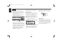
KDC-4020(M)Cover
01.11.29
10:32 AM
Page 1
KDC-4020
KDC-3020
KDC-2020
KDC-1020
KDC-1020S
CD-RECEIVER
INSTRUCTION MANUAL
© B64-2115-00 (MWN/IW)
KDC-4020_U.S
01.11.29
10:28 AM
Page 2
English
Contents
Safety precautions......................3
About CDs...................................5
General features .........................6
Power
Selecting the Source
Volume
Attenuator
Loudness
System Q
Audio Control
Speaker Setting
Clock Display
Adjusting Clock
DSI (Disabled System Indicator)
Theft Deterrent Faceplate
Tuner features .............................9
Tuning Mode
Tuning
Station Preset Memory
Auto Memory Entry
Preset Tuning
CRSC (Clean Reception System Circuit)
Frequency Step Setting
CD/External disc control
features ..................................11
Playing CD
Playing External Disc
Fast Forwarding and Reversing
Track Search
Album Search
Track/Album Repeat
Track Scan
Random Play
Magazine Random Play
Basic Operations of remote......13
Loading and Replacing the battery
Basic operations
In Tuner source
In Disc source
Accessories ...............................15
Installation Procedure ..............15
Connecting Wires to Terminals 16
Installation ................................17
Troubleshooting Guide .............19
Specifications ...........................22
—2—
KDC-4020_U.S
01.11.29
10:28 AM
Page 3
Safety precautions
2WARNING
2CAUTION
To prevent injury or fire, take the
following precautions:
To prevent damage to the machine,
take the following precautions:
• Insert the unit all the way in until it is fully
locked in place. Otherwise it may fall out of
place when jolted.
• When extending the ignition, battery, or
ground wires, make sure to use automotivegrade wires or other wires with a 0.75mm2
(AWG18) or more to prevent wire
deterioration and damage to the wire
coating.
• To prevent a short circuit, never put or leave
any metallic objects (such as coins or metal
tools) inside the unit.
• If the unit starts to emit smoke or strange
smells, turn off the power immediately and
consult your Kenwood dealer.
• Make sure not to get your fingers caught
between the faceplate and the unit.
• Be careful not to drop the unit or subject it to
strong shock.
The unit may break or crack because it
contains glass parts.
• Do not touch the liquid crystal fluid if the
LCD is damaged or broken due to shock. The
liquid crystal fluid may be dangerous to your
health or even fatal.
If the liquid crystal fluid from the LCD
contacts your body or clothing, wash it off
with soap immediately.
• Make sure to ground the unit to a negative
12V DC power supply.
• Do not open the top or bottom covers of the
unit.
• Do not install the unit in a spot exposed to
direct sunlight or excessive heat or humidity.
Also avoid places with too much dust or the
possibility of water splashing.
• Do not set the removed faceplate or the
faceplate case in areas exposed to direct
sunlight, excessive heat or humidity. Also
avoid places with too much dust or the
possibility of water splashing.
• To prevent deterioration, do not touch the
terminals of the unit or faceplate with your
fingers.
• Do not subject the faceplate to excessive
shock, as it is a piece of precision
equipment.
• When replacing a fuse, only use a new one
with the prescribed rating. Using a fuse with
the wrong rating may cause your unit to
malfunction.
• To prevent a short circuit when replacing a
fuse, first disconnect the wiring harness.
• Do not place any object between the
faceplate and the unit.
• Do not use your own screws. Use only the
screws provided. If you use the wrong
screws, you could damage the unit.
—3—
IMPORTANT INFORMATION
About the disc changer to be
connected:
To connect a disc changer having the "O-N"
switch to this unit, set the "O-N" switch to "N".
To connect a disc changer having no "O-N"
switch to this unit, the converter cord CADS100 and/or switching adapter KCA-S210A
are required as options.
A disc changer doesn't work when it is
connected without using these options.
If a model with no "O-N" switch is connected,
some unavailable functions and information
that cannot be displayed are generated.
Note that none of the KDC-C100, KDC-C302,
C205, C705, and non-Kenwood CD changers
can be connected.
You can damage both your unit and the CD
changer if you connect them incorrectly.
Do Not Load 3-in. CDs in the CD slot
If you try to load a 3 in. CD with its adapter
into the unit, the adapter might separate from
the CD and damage the unit.
English
KDC-4020_U.S
01.11.29
10:28 AM
Page 4
NOTE
• If you experience problems during
installation, consult your Kenwood dealer.
• If the unit does not seem to be working
right, try pressing the reset button first. If
that does not solve the problem, consult
your Kenwood dealer.
• Press the reset button if the Disc auto
changer fails to operate correctly. Normal
operatin should be restored.
Reset button
• Characters in the LCD may become difficult
to read in temperatures below 41 ˚F (5 ˚C).
• The illustrations of the display and the panel
appearing in this manual are examples used
to explain more clearly how the controls are
used. Therefore, what appears on the display
in the illustrations may differ from what
appears on the display on the actual
equipment, and some of the illustrations on
the display may represent something
impossible in actual operation.
Cleaning the Faceplate Terminals
Cleaning the CD Slot
If the terminals on the unit or faceplate get
dirty, wipe them with a dry, soft cloth.
As dust tends to accumulate in the CD slot,
clean it every once in a while. Your CDs can
get scratched if you put them in a dusty CD
slot.
Cleaning the Unit
If the faceplate of this unit is stained, wipe it
with a dry soft cloth such as a silicon cloth.
If the faceplate is stained badly, wipe the stain
off with a cloth moistened with neutral
cleaner, then wipe neutral detergent off.
Applying spray cleaner directly to the unit may
affect its mechanical parts. Wiping the
faceplate with a hard cloth or using a volatile
liquid such as thinner or alcohol may scratch
the surface or erases characters.
The marking of products using lasers
(Except for some areas)
CLASS 1
LASER PRODUCT
The label is attached to the chassis/case and
says that the component uses laser beams
that have been classified as Class 1. It
means that the unit is utilizing laser beams
that are of a weaker class. There is no
danger of hazardous radiation outside the
unit.
—4—
Lens Fogging
Right after you turn on the car heater in cold
weather, dew or condensation may form on
the lens in the CD player of the unit. Called
lens fogging, CDs may be impossible to play.
In such a situation, remove the disc and wait
for the condensation to evaporate. If the unit
still does not operate normally after a while,
consult your Kenwood dealer.
KDC-4020_U.S
01.11.29
10:28 AM
Page 5
About CDs
Handling CDs
CD cleaning
• Don’t touch the recording surface of the CD.
Clean from the center of the disc and move
outward.
Removing CDs
• CD-R and CD-RW are easier to damage than
a normal music CD. Use a CD-R or a CD-RW
after reading the caution items on the
package etc.
• Don’t stick tape etc. on the CD.
Also, don’t use a CD with tape stuck on it.
When removing CDs from this unit pull them
out horizontally.
CDs that can’t be used
• CDs that aren’t round can’t be used.
When using a new CD
If the CD center hole or outside rim has burrs,
use it after removing them with a ball pen etc.
Burrs
Burrs
• CDs with coloring on the recording surface
or that are dirty can’t be used.
• Don’t use CDs without disc mark
.
• A CD-R or CD-RW that hasn’t been finalized
can’t be played. (For the finalization process
refer to your CD-R/CD-RW writing software,
and your CD-R/CD-RW recorder instruction
manual.)
CD storage
CD accessories
Don’t use disc type accessories.
• Don’t place them in direct sunlight (On the
seat or dashboard etc.) and where the
temperature is high.
• Store CDs in their cases.
—5—
KDC-4020_U.S
01.11.29
10:28 AM
Page 6
English
General features
Power
Release button
(KDC-4020/KDC-3020/KDC-2020 only)
AM
ud
4 ¢
FM
Turning ON the Power
Press the [SRC] button.
Turning OFF the Power
Press the [SRC] button for at least 1 second.
Selecting the Source
SRC ATT/ #1
LOUD
#3
CLK/
ADJ
Press the [SRC] button.
Source required
Display
Tuner
"TUnE"
CD
"CD"
External disc
"DISC"
(Function of the KDC-4020/KDC-3020/KDC-2020)
Standby (Illumination only mode)
"OFF"
Q/
AUD
KDC-4020/KDC-3020/KDC-2020
ATT indicator LOUD indicator
Volume
Clock display
Clock indicator
SYSTEM Q indicator
Increasing Volume
Press the [u] button.
Decreasing Volume
Press the [d] button.
KDC-1020/KDC-1020S
LOUD indicator
Clock display
Attenuator
Turning the volume down quickly.
Press the [ATT] button.
Each time the button is pressed the Attenuator turns ON or OFF.
When it’s ON, the "ATT" indicator blinks.
ATT indicator
SYSTEM Q indicator
Clock indicator
—6—
KDC-4020_U.S
01.11.29
10:28 AM
Page 7
Loudness
Compensating for low and high tones during low volume.
Press the [LOUD] button for at least 1 second.
Each time the button is pressed for at least 1 second the
Loudness turns ON or OFF.
When it’s ON, "LOUD" indicator is ON.
Audio Control
1
Select the source for adjustment
Press the [SRC] button.
2
Enter Audio Control mode
Press the [AUD] button for at least 1 second.
3
Select the Audio item for adjustment
Press the [FM] or [AM] button.
Each time the button is pressed the items that can be adjusted
switch as shown below.
4
Adjust the Audio item
Press the [4] or [¢] button.
Adjustment Item
Display
Bass level
"BAS"
Middle level
"MID"
Treble level
"TRE"
Balance
"BL"
Fader
"FD"
System Q
You can recall the best sound setting preset for different types of
the music.
1
Select the source to set
Press the [SRC] button.
2
Select the Sound type
Press the [Q] button.
Each time the button is pressed the sound setting switches.
Sound setting
Display
Flat
"SQ-1"
Rock
"SQ-2"
Top 40
"SQ-3"
Pops
"SQ-4"
Jazz
"SQ-5"
Easy
"SQ-6"
Scan of Flat — Easy
"SCAn"
5
• Each setting value is changed with the <Speaker setting> (page
8).
First, select the speaker type with the Speaker setting.
• When the System Q setting is changed, the Bass, Middle, and
Treble set in audio control replace the System Q values.
—7—
Exit Audio Control mode
Press the [AUD] button.
Range
–8 — +8
–8 — +8
–8 — +8
Left 15 — Right 15
Rear 15 — Front 15
KDC-4020_U.S
01.11.29
10:28 AM
Page 8
English
General features
Press the [CLK] button.
Speaker Setting
Fine-tuning so that the System Q value is optimal when setting
the speaker type.
1
Enter Standby
Press the [SRC] button.
Select the "OFF" display.
2
Enter Speaker Setting mode
Press the [Q] button.
3
Select the Speaker type
Press the [4] or [¢] button.
Each time the button is pressed the
below.
Speaker type
OFF
For the OEM speaker
For 6 & 6x9 in. speaker
For 5 & 4 in. speaker
4
Adjust the hours
Press the [FM] or [AM] button.
Exit clock adjustment mode
Press the [CLK] button.
setting switches as shown
Function of the KDC-4020/KDC-3020/KDC-2020
Display
"SP-F"
"SP-O"
"SP-6"
"SP-5"
Press the [CLK] button.
Each time the button is pressed the clock display turns ON or
OFF.
When it’s ON, the clock indicator is ON.
Select the clock display
3
4
Clock Display
1
Enter clock adjustment mode
Press the [CLK] button for at least 2 seconds.
The clock display blinks.
Adjust the minutes
Press the [4] or [¢] button.
Exit Speaker Setting mode
Press the [Q] button.
Adjusting Clock
2
DSI (Disabled System Indicator)
A red indicator will blink on the unit after the faceplate is
removed, warning potential thieves.
1
Turn the power OFF
Press the [SRC] button for at least 1 second.
2
Set the DSI
While pressing the [#1] and [#3] button, press the [SRC]
button.
Each time the step 1 and 2 operation is done the DSI turns ON or
OFF.
Function of the KDC-4020/KDC-3020/KDC-2020
Theft Deterrent Faceplate
The faceplate of the unit can be detached and taken with you,
helping to deter theft.
Removing the Faceplate
Press the Release button.
The faceplate is unlocked, allowing you to detach it.
—8—
KDC-4020_U.S
01.11.29
10:28 AM
Page 9
Tuner features
• The faceplate is a precision piece of equipment and can be
damaged by shocks or jolts. For that reason, keep the faceplate in
its special storage case while detached.
• Do not expose the faceplate or its storage case to direct sunlight
or excessive heat or humidity. Also avoid places with too much
dust or the possibility of water splashing.
AM
FM/
CRSC
4 ¢
Reattaching the Faceplate
1
Align the projections on the unit with the grooves on the
faceplate.
SRC
2
#1 - 6
AUTO/
AME
KDC-4020/KDC-3020/KDC-2020
ST indicator
Preset station number
Push the faceplate in until it clicks.
The faceplate is locked in place, allowing you to use the unit.
Band display
AUTO indicator
Frequency display
KDC-1020/KDC-1020S
Band display
Preset station number
ST indicator
CRSC indicator
AUTO indicator
Frequency display
—9—
CRSC indicator
KDC-4020_U.S
01.11.29
10:28 AM
Page 10
English
Tuner features
Press the [FM] or [AM] button.
Tuning Mode
Choose the tuning mode.
Press the [AUTO] button.
Each time the button is pressed the Tuning mode switches as
shown below.
Tuning mode
Display
Operation
Auto seek
"AUTO 1"
Automatic search for a station.
indicator
Preset station
"AUTO 2"
Search in order of the stations
seek
indicator
in the Preset memory.
Manual
—
Normal manual tuning control.
2
Select the frequency to put in the memory
Press the [4] or [¢] button.
3
Put the frequency in the memory
Press the [#1] — [#6] button for at least 2 seconds.
The preset number display blinks 1 time.
On each band, 1 station can be put in the memory on each [#1]
— [#6] button.
Auto Memory Entry
Putting stations with good reception in the memory
automatically.
Tuning
1
Select the band for Auto Memory Entry
Press the [FM] or [AM] button.
2
Open Auto Memory Entry
Press the [AME] button for at least 2 seconds.
When 6 stations that can be received are put in the memory
Auto Memory Entry closes.
Selecting the station.
1
Select tuner source
Press the [SRC] button.
Select the "TUnE" display.
2
Select the band
Press the [FM] or [AM] button.
Each time the [FM] button is pressed it switches between the
FM1, FM2, and FM3 bands.
3
Tune up or down band
Press the [4] or [¢] button.
During reception of stereo stations the "ST" indicator is ON.
Preset Tuning
Calling up the stations in the memory.
1
Select the band
Press the [FM] or [AM] button.
2
Call up the station
Press the [#1] — [#6] button.
Station Preset Memory
Putting the station in the memory.
1
Select the band
CRSC (Clean Reception System Circuit)
Temporarily have reception switched from stereo to mono to
reduce multi-path noise when listening to the FM station.
— 10 —
KDC-4020_U.S
01.11.29
10:28 AM
Page 11
CD/External disc control features
Press the [CRSC] button for at least 1 second.
Each time the button is pressed CRSC turns ON or OFF.
When it's ON, the "CRSC" indicator is ON.
DISC-
0
DISC+
4 ¢
Frequency Step Setting
Changing the tuning frequency step.
The original setting is FM band 50 kHz, and AM band 9 kHz.
1
Turn the power OFF
Press the [SRC] button for at least 1 second.
2
Switch the frequency step
While pressing the [#1] and [#5] button, press the [SRC]
button.
The frequency step changes to FM band 200 kHz, and AM band
10 kHz.
SRC
SCAN
REP
RDM
M.RDM
KDC-4020/KDC-3020/KDC-2020
Track number
• When the same operation is repeated, it returns to the original
setting.
• When the frequency step is switched, the frequencies in the
memory are deleted.
IN indicator
Disc number
Track time
SCN indicator
REP indicator
RDM indicator
KDC-1020/KDC-1020S
Track number
IN indicator
Track time
— 11 —
RDM indicator
SCN indicator
REP indicator
KDC-4020_U.S
01.11.29
10:28 AM
Page 12
English
CD/External disc control features
Reversing
Hold down on the [4] button.
Release your finger to play the disc at that point.
Playing CD
When a CD is inserted
Press the [SRC] button.
Select the "CD" display.
Track Search
When a CD is inserted, the "IN" indicator is ON.
Selecting the song you want to hear.
Eject the CD
Press the [0] button.
Press the [4] or [¢] button.
3 in. (8cm) CD cannot be played. Using an adapter and inserting
them into this unit can cause damage.
Function of the KDC-4020/KDC-3020/KDC-2020
Album Search (Function of disc changer)
Function of the KDC-4020/KDC-3020/KDC-2020
Selecting the disc you want to hear.
Playing External Disc
Playing discs set in the optional accessory disc player connected
to this unit.
Press the [SRC] button.
Select the display for the disc player you want.
Display examples:
Display
Disc player
"CD-2"
CD player
"DISC"
CD changer
"DISC"
MD changer
Press the [DISC–] or [DISC+] button.
Track/Album Repeat
Replaying the song/disc you're listening to.
Press the [REP] button.
Each time the button is pressed the Repeat Play switches as
shown below.
Repeat play
Display
Track Repeat
"REP" indicator & Track No. blink.
Album Repeat
"REP" indicator & Disc No. blink.
(Function of disc changer)
OFF
—
• Disc #10 is displayed as "0".
• The functions that can be used and the information that can be
displayed will differ depending on the external disc players being
connected.
Fast Forwarding and Reversing
Fast Forwarding
Hold down on the [¢] button.
Release your finger to play the disc at that point.
— 12 —
KDC-4020_U.S
01.11.29
10:28 AM
Page 13
Basic Operations of remote
Accessory of the KDC-4020
Track Scan
Playing the first part of each song on the disc you are listening
to and searching for the song you want to listen to.
1
Start Track Scan
Press the [SCAN] button.
"SCN" indicator is ON.
2
Release it when the song you want to listen to is played
Press the [SCAN] button.
4/¢
Random Play
FM/AM/DISC
Playing all the songs on the disc in random order.
38
Press the [RDM] button.
Each time the button is pressed Random Play turns ON or OFF.
When it's ON, the "RDM" indicator is ON and the track number
blinks.
When the [¢] button is pressed, the next song select starts.
ATT
VOL.
Function of the KDC-4020/KDC-3020/KDC-2020
Magazine Random Play
(Function of disc changer)
Play the songs on all the discs in the disc changer in random
order.
Press the [M.RDM] button.
Each time the button is pressed the Magazine Random Play turns
ON or OFF.
When it's ON, the "RDM" indicator is ON and the track and disc
number blink.
When the [¢] button is pressed, the next song select starts.
— 13 —
SRC
KDC-4020_U.S
01.11.29
10:28 AM
Page 14
Basic Operations of remote
English
Accessory of the KDC-4020
Loading and Replacing the battery
Use one lithium battery (CR2025).
Insert the batteries with the + and – poles aligned properly,
following the illustration inside the case.
In Tuner source
[FM]/ [AM] buttons
Select the band.
Each time the [FM] button is pressed it switches between the
FM1, FM2, and FM3 bands.
[4]/ [¢] buttons
Tune up or down band.
In Disc source
2WARNING
Store unused batteries out of the reach of children. Contact a doctor
immediately if the battery is accidentally swallowed.
Do not set the remote on hot places such as above the dashboard.
[4]/ [¢] buttons
Doing track forward and backward.
[DISC+]/ [DISC-] buttons
Doing album forward and backward.
[38] button
Each time the button is pressed the song pauses and plays.
Basic operations
[VOL.] buttons
Adjusting the volume.
[SRC] button
Each time the button is pressed the source switches.
For the source switching order refer to <Selecting the Source>
(page 6).
[ATT] button
Turning the volume down quickly.
When it is pressed again it returns to the previous level.
— 14 —
KDC-4020_U.S
01.11.29
10:28 AM
Page 15
Accessories
External view
......... Number of items
External view
......... Number of items
1
3
.........1
.........4
2WARNING
If you connect the ignition wire (red) and the battery wire (yellow)
to the car chassis (ground), you may cause a short circuit, that in
turn may start a fire. Always connect those wires to the power
source running through the fuse box.
2CAUTION
2
.........2
4
.........4
5
.........1
(KDC-4020/KDC-3020/KDC-2020 only)
The use of any accessories except for those provided might result in
damage to the unit. Make sure only to use the accessories shipped with
the unit, as shown above.
Installation Procedure
1. To prevent a short circuit, remove the key from the ignition and
disconnect the - battery.
2. Make the proper input and output wire connections for each unit.
3. Connect the speaker wires of the wiring harness.
4. Connect the wiring harness wires in the following order: ground,
battery, ignition.
5. Connect the wiring harness connector to the unit.
6. Install the unit in your car.
7. Reconnect the - battery.
8. Press the reset button.
• If your car's ignition does not have an ACC position, connect the
ignition wires to a power source that can be turned on and off
with the ignition key. If you connect the ignition wire to a power
source with a constant voltage supply, as with battery wires, the
battery may die.
• If the console has a lid, make sure to install the unit so that the
faceplate will not hit the lid when closing and opening.
• If the fuse blows, first make sure the wires aren’t touching to
cause a short circuit, then replace the old fuse with one with the
same rating.
• Insulate unconnected wires with vinyl tape or other similar
material. To prevent a short circuit, do not remove the caps on
the ends of the unconnected wires or the terminals.
• Connect the speaker wires correctly to the terminals to which
they correspond. The unit may be damaged or fail to work if you
share the - wires or ground them to any metal part in the car.
• When only two speakers are being connected to the system,
connect the connectors either to both the front output terminals
or to both the rear output terminals (do not mix front and rear).
For example, if you connect the + connector of the left speaker
to a front output terminal, do not connect the - connector to a
rear output terminal
• After the unit is installed, check whether the brake lamps,
blinkers, wipers, etc. on the car are working properly.
• Mount the unit so that the mounting angle is 30° or less.
— 15 —
KDC-4020_U.S
01.11.29
10:28 AM
Page 16
English
Connecting Wires to Terminals
Front left output (White) (KDC-4020 only) 26
Front right output (Red) (KDC-4020 only) 27
Rear left output (White) 23
2 KENWOOD disc changer control input (KDC-4020/3020/2020 only)
Rear right output (Red) 28
To connect the Disc changer, consult your
Disc changer manual. 3
REAR
L
FM/AM antenna input 1
Fuse (10A) 24
If no connections are made, do not let the wire come out from the tab.4
5 When using the optional power amplifier,
connect to its power control terminal.
P.CONT
R
Wiring harness
(Accessory1)25
Power control wire (Blue/White) 15
29
White/Black
To front left
speaker 30
FRONT • L
7 Depending on what antenna you are using,
connect either to the control terminal of the
motor antenna, or to the power terminal for
the booster amplifier of the film-type antenna.
White
32 31
Gray/Black
ANT.
CONT.
Motor antenna control wire (Blue)
17
To front right
speaker 33
FRONT • R
Gray
34
35
Green/Black
To rear left
speaker 36
REAR • L
Green
37
38
Purple/Black
Ignition key
switch
10
ACC 13
Ignition wire (Red) 20
Battery wire (Yellow) 21
Car fuse box
(Main fuse)
11
Car fuse
box 14
+
–
Ground wire (Black) · (To car chassis) 22
Battery 12
— 16 —
To rear right
speaker 39
REAR • R
Purple
40
KDC-4020_U.S
01.11.29
10:28 AM
Page 17
Installation
■ Installation
■ Installing in Japanese-Made Cars
Firewall or metal support
Screw (M4X8)
(commercially
available)
1
Refer to the section "Removing the hard rubber frame" (page 18)
and then remove the hard rubber frame.
2
Align the holes in the unit (two locations on each side) with the
vehicle mounting bracket and secure the unit with the accessory
screws.
T
N
8 mm
MAX.
N
Self-tapping screw
(commercially available)
Metal mounting strap
(commercially available)
T/N
T: Toyota cars
N: Nissan cars
8mm
MAX.
3
ø5mm
Bend the tabs of the
mounting sleeve
with a screwdriver or
similar utensil and
attach it in place.
Make sure that the unit is installed securely in place. If the unit is
unstable, it may malfunction (for example, the sound may skip).
T
4
ø5mm
Accessory3...for Nissan car
Accessory4 ...for Toyota car
• During installation, do not use any screws except for those provided.
The use of different screws might result in damage to the main unit.
• Damage may occur if a screwdriver or similar tool is used with
excessive force during the installations.
■ Screwing the Faceplate on the Unit
If you want to fasten the
faceplate to the main unit so
that it does not fall off,
screw in the provided screw
(ø4 X 16 mm) in the hole
shown below.
Accessory5
Never insert the taptite screw (ø4 × 16 mm) in any other screw hole
than the one specified. If you screw it in another hole, it will contact
and may cause damage to the mechanical parts inside the unit.
— 17 —
KDC-4020_U.S
01.11.29
10:28 AM
Page 18
English
Installation
■ Removing the hard rubber frame
■ Removing the Unit
1
1
Refer to the section “Removing the hard rubber frame” and then
remove the hard rubber frame.
2
3
Remove the screw (M4 × 8) on the back panel.
Engage the catch pins on the removal tool and remove the two
locks on the lower level.
Lower the frame and pull it forward as shown in the figure.
Catch
Insert the two removal tools deeply into the slots on each side,
as shown.
Lock
Screw (M4X8)
(commercially
available)
Accessory2
Removal tool
2
When the lower level is removed, remove the upper two
locations.
4
Lower the removal tool
toward the bottom, and pull
out the unit halfway while
pressing towards the inside.
Be careful to avoid injury from
the catch pins on the removal
tool.
5
The frame can be removed from the top side in the same manner.
— 18 —
Pull the unit all the way out
with your hands, being
careful not to drop it.
Accessory2
Removal tool
KDC-4020_U.S
01.11.29
10:28 AM
Page 19
Troubleshooting Guide
What might seem to be a malfunction in your unit may
just be the result of slight misoperation or miswiring.
Before calling service, first check the following table
for possible problems.
?
✔ The speakers are not wired correctly.27
☞ Reconnect the speaker wires so that each output terminal is
connected to a different speaker.
General
?
The sound quality is poor or distorted.25
✔ One of the speaker wires is being pinched by a screw in the car.
☞ Check the speaker wiring.
The power does not turn ON.01
✔ The fuse has blown.
☞ After checking for short circuits in the wires, replace the fuse with
one with the same rating.
?
✔ No ACC position on vehicle ignition.02
☞ Connect the same wire to the ignition as the battery wire.
Tuner source
?
Nothing happens when the buttons are pressed.04
✔ The computer chip in the unit is not functioning normally.
☞ Press the reset button on the unit (page 4).
?
There’s a source you can’t switch.06
✔ There’s no CD inserted.
☞ Set the media you want to listen to. If there’s no media in this
unit, you can't swhich to each source.
?
The memory is erased when the ignition is turned OFF.10
✔ The battery wire has not been connected to the proper terminal.
☞ Connect the wire correctly, referring to the section on
<Connecting Wires to Terminals>.
?
The Touch Sensor Tone doesn’t sound.34
✔ The preout jack is being used.
☞ The Touch Sensor Tone can’t be output from the preout jack.
Radio reception is poor.39
✔ The car antenna is not extended.
☞ Pull the antenna out all the way.
✔ The antenna control wire is not connected.40
☞ Connect the wire correctly, referring to the section on
<Connecting Wires to Terminals>.
✔ The ignition and battery wire are incorrectly connected.11
☞ Connect the wire correctly, referring to the section on
<Connecting Wires to Terminals>.
?
Even if Loudness is turned ON, high-pitched tone isn't compensated
for. 17
✔ Tuner source is selected.
☞ High-pitched tone isn't compensated for when in Tuner source.
?
No sound can be heard, or the volume is low.
✔ The fader or balance settings are set all the way to one side.21
☞ Center the fader and balance settings.
✔ The input/output wires or wiring harness are connected incorrectly.22
☞ Reconnect the input/output wires or the wiring harness correctly.
See the section on "Connecting Wires to Terminals".
— 19 —
KDC-4020_U.S
01.11.29
10:28 AM
Page 20
English
Troubleshooting Guide
?
Disc source
?
"AVin" is displayed without achieving External disc control mode.50
✔ O-N switch is set to "O" side.
☞ Set the switch to "N" side.
✔ Unsupported disc changer is connected.51
☞ Connect the supported disc changer. (page 3)
?
Can’t remove disc.64
✔ The cause is that more than 10 minutes has elapsed since the vehicle
ACC switch was turned OFF.
☞ The disc can only be removed within 10 minutes of the ACC
switch being turned OFF. If more than 10 minutes has elapsed,
turn the ACC switch ON again and press the Eject button.
?The disc won’t insert.65
✔ There’s already another disc inserted.
☞ Press the [0] button and remove the disc.
The specified disc does not play, but another one plays instead.52
✔ The specified CD is quite dirty.
☞ Clean the CD.
?Track Search can't be done.66-2
✔ The CD is upside-down.53
☞ Load the CD with the labeled side up.
✔ For the albums first or last song.
☞ For each album, Track Search can't be done in the backward
direction for the first song or in the forward direction for the last
song.
✔ The disc is loaded in a different slot from that specified.54
☞ Eject the disc magazine and check the number for the specified
disc.
✔ The disc is severely scratched.55
☞ Try another disc instead.
If the following situations, consult your nearest service
center:
?
The specified track will not play.58
✔ Random play or magazine random play has been selected.
☞ Turn off random play or magazine random play.
?
Track repeat, disc repeat, track scan, random play, and magazine
random play start by themselves.59
✔ The setting is not canceled.
☞ The settings for these functions remain on until the setting to off
or the disc ejected, even if the power is turned off or the source
changed.
• Even though the disc changer is connected, the Disc Changer source is
not ON, with "AVin" showing in the display during the Changer Mode.
• Even though no device (KCA-S210A, CA-C1AX, KDC-CPS87, KDC-CX87,
KDC-CPS85, KDC-CX85, KDC-CPS82 or KDC-CX82) is connected, the
Auxiliary input is entered when switching modes.
?
Cannot play CD-R or CD-RW.60
✔ Finalization processing is not being conducted for CD-R/CD-RW.
☞ Conduct finalization processing with CD recorder.
✔ A non-compatible CD changer is being used to play the CD-R/CDRW.61
☞ Use a CD changer compatible with CD-R/CD-RW to play.
?
A CD ejects as soon as it is loaded.62
✔ The CD is upside-down.
☞ Load the CD with the labeled side up.
✔ The CD is quite dirty.63
☞ Clean the CD, referring to the section on <CD cleaning> (page 5).
— 20 —
KDC-4020_U.S
01.11.29
10:28 AM
Page 21
Troubleshooting Guide
The messages shown below display your systems
condition.
E-01:
No disc magazine has been loaded in the changer.
The disc magazine is not completely loaded.E01
➪ Load the disc magazine properly.
No CD in the unit.
➪ Insert the CD.
E-02:
No disc has been loaded in the disc magazine.E02
➪ Load a disc into the disc magazine.
E-04:
E-0d:
The protective circuit in the unit activates when the
temperature inside the automatic disc changer
exceeds 60°C (140°F), stopping all operation.E0d
➪ Cool down the unit by opening the windows or
turning on the air conditioner. As the temperature
falls below 60°C (140°F), the disc will start playing
again.
LOAd:
Discs are being exchanged in the Disc changer.E57
IN (Blink):
The CD player section is not operating properly.E59
➪ Reinsert the CD. If the CD cannot be ejected or the
No disc has been loaded in the disc magazine.E04
➪ Load a disc into the disc magazine.
The CD is quite dirty. The CD is upside-down. The CD
is scratched a lot.
➪ Clean the CD and load it correctly.
E-10:
Nothing has been recorded on the MD.E10
E-11:
No tracks are recorded on the MD, although it has a
title.E11
E-12:
The faceplate of the slave unit being connected to
this unit has been removed.E30
➪ Replace it.
E-77:
The unit is malfunctioning for some reason.E77
➪ Press the reset button on the unit. If the "E- 77"
code does not disappear, consult your nearest
service center.
E-99:
Something is wrong with the disc magazine. Or the
unit is malfunctioning for some reason.E99
➪ Check the disc magazine. And then press the reset
button on the unit. If the "E-99" code does not
disappear, consult your nearest service center.
— 21 —
display continues to flash even when the CD has
been properly reinserted, please switch off the
power and consult your nearest service center.
KDC-4020_U.S
01.11.29
10:28 AM
Page 22
English
Specifications
Specifications subject to change without notice.
FM tuner section
Audio section
Frequency range (200 kHz space) ............87.9 MHz – 107.9 MHz
Frequency range (50 kHz space) ..............87.5 MHz – 108.0 MHz
Usable sensitivity (S/N = 30dB) ....................9.3dBf (0.8 µV/75 Ω)
Quieting Sensitivity (S/N = 50dB) ...............15.2dBf (1.6 µV/75 Ω)
Frequency response (±3 dB) .................................30 Hz – 15 kHz
Signal to Noise ratio (MONO) ..............................................70 dB
Selectivity (±400 kHz).......................................................≥ 80 dB
Stereo separation (1 kHz) ....................................................40 dB
AM tuner section
Maximum output power.................................................50 W x 4
Full Bandwidth Power (at less than 1% THD) ................22 W x 4
Tone action
Bass : ...............................................................100 Hz ±10 dB
Middle : ..............................................................1 kHz ±10 dB
Treble : .............................................................10 kHz ±10 dB
Preout level / Load (during disc play)....................1800 mV/10 kΩ
Preout impedance ............................................................≤ 600 Ω
General
Frequency range (10 kHz space) ...................530 kHz – 1700 kHz
Frequency range (9 kHz space) .....................531 kHz – 1611 kHz
Usable sensitivity (S/N = 20dB) .............................28 dBµ (25 µV)
CD player section
Operating voltage (11 – 16V allowable) ..............................14.4 V
Current consumption.............................................................10 A
Installation Size (W x H x D) ..........................182 x 53 x 157 mm
7-3/16 x 2-1/16 x 6-3/16 inch
Weight...................................................................3.1 lbs (1.4 kg)
Laser diode ....................................................GaAlAs (λ=780 nm)
Digital filter (D/A)......................................8 Times Over Sampling
D/A Converter .......................................................................1 Bit
Spindle speed ...............................................500 – 200 rpm (CLV)
Wow & Flutter........................................Below Measurable Limit
Frequency response (±1 dB) .................................10 Hz – 20 kHz
Total harmonic distortion (1 kHz) ......................................0.01 %
Signal to Noise ratio (1 kHz) ................................................96 dB
Dynamic range ....................................................................93 dB
Channel separation..............................................................85 dB
— 22 —