1
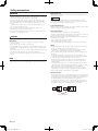
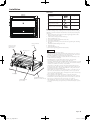
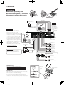
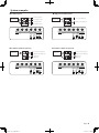
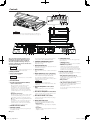
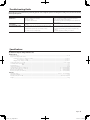
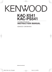
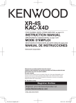
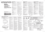
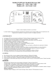
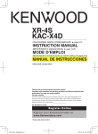
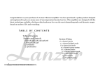
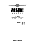
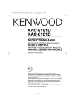
KAC-X41 FOUR CHANNEL POWER AMPLIFIER INSTRUCTION MANUAL © B64-4200-00/00 (MV) KAC-X41_M_1English.indd 1 08.10.21 3:48:31 PM Safety precautions WARNING Cleaning the unit If the front panel gets dirty, turn off the power and wipe the panel with a dry silicon cloth or soft cloth. To prevent injury or fire, take the following precautions: • Mounting and wiring this product requires skills and experience. For safety’s sake, leave the mounting and wiring work to professionals. • When extending the ignition, battery, or ground wires, make sure to use automotive-grade wires or other wires with the range of 14 mm2 (AWG 6) to 21 mm2 (AWG 4) to prevent wire deterioration and damage to the wire coating. • To prevent a short circuit, never put or leave any metallic objects (such as coins or metal tools) inside the unit. • If the unit starts to emit smoke or strange smells, turn off the power immediately and consult your Kenwood dealer. • Do not touch the unit during use because the surface of the unit becomes hot and may cause burns if touched. CAUTION Do not wipe the panel with a hard cloth or a cloth dampened by volatile solvents such as paint thinner and alcohol. They can scratch the surface of the panel and/or cause the indicator letters to peel off. To prevent battery rise When the unit is used in the ACC ON position without turning the engine ON, it depletes the battery. Use it after starting the engine. Protection function The protection function is activated in the following situations: This unit is equipped with a protection function for protecting this unit and your speakers from various accidents or problems that can occur. When the protection function is triggered, the PROTECTION indicator lights and the amplifier stops operating. • When a speaker wire may be short-circuited. • When a speaker output contacts ground. • When the unit malfunctions and a DC signal is sent to the speaker output. CAUTION To prevent damage to the machine, take the following precautions: • Be sure the unit is connected to a 12V DC power supply with a negative ground connection. • Do not open the top or bottom covers of the unit. • Do not install the unit in a spot exposed to direct sunlight or excessive heat or humidity. Also avoid places with too much dust or the possibility of water splashing. • When replacing a fuse, only use a new one with the prescribed rating. Using a fuse with the wrong rating may cause your unit to malfunction. • To prevent a short circuit when replacing a fuse, first disconnect the wiring harness. Wiring • Take the battery wire for this unit directly from the battery. If it’s connected to the vehicle’s wiring harness, it can cause blown fuses etc. • If a buzzing noise is heard from the speakers when the engine is running, connect a line noise filter (optional) to each of the battery wire. • Do not allow the wire to directly contact the edge of the iron plate by using Grommets. • Connect the ground wire to a metal part of the car chassis that acts as an electrical ground passing electricity to the battery‘s negative - terminal. Do not turn the power on if the ground wire is not connected. • Be sure to install a protective fuse in the power cord near the battery. The protective fuse should be the same capacity as the unit’s fuse capacity or somewhat larger. • For the power cord and ground, use a vehicle type (fireproof ) power wring cord with a current capacity greater than the unit’s fuse capacity. (Use a power wiring cord with the range of 14 mm2 (AWG 6) to 21 mm2 (AWG 4). • When more than one power amplifier are going to be used, use a power supply wiring wire and protective fuse of greater current-handling capacity than the total maximum current drawn by each amplifier. NOTE • If you experience problems during installation, consult your Kenwood dealer. • If the unit does not seem to be working right, consult your Kenwood dealer. Speaker Selection • The rated input power of the speakers that are going to be connected should be greater than the maximum output power (in Watts) of the amplifier. Use of speakers having input power ratings that are less than the output power of the amplifier will cause smoke to be emitted as well as damage. • Use speakers that have an impedance of 2Ω or greater. When more than one set of speakers are going to be used, calculate the combined impedance of the speakers and then connect suitable speakers to the amplifier. 4Ω 4Ω 4Ω 4Ω 4Ω 4Ω 4Ω 2Ω 8Ω 4Ω 4Ω 4Ω 4Ω 4Ω 4Ω 4Ω 4Ω 4Ω 4Ω Combined impedance 4Ω 4Ω 4Ω 8Ω 2Ω English KAC-X41_M_1English.indd 2 08.10.21 3:48:32 PM Installation Accessories ø6 Part name 380 mm 320 mm 286 mm 272 mm Hexagon Wrench (Small) Hexagon socket head cap screw (M4 × 8 mm) Dressing cover Cooling fan Self-tapping screw (ø5 × 18 mm) External View Number of Items Self-tapping screws (ø5 × 18 mm) 4 Hexagon Wrench (Large) 1 Hexagon Wrench (Small) 1 Terminal cover (Power terminal) 1 Installation procedure Since there are large variety of settings and connections possible according to applications, read the instruction manual well to select the proper setting and connection. 1. Remove the ignition key and disconnect the negative · terminal of the battery to prevent short circuits. 2. Set the unit according to the intended usage. 3. Remove the Dressing cover. 4. Connect the input and output wires of the units. 5. Connect the speaker wires. 6. Connect the power wire, power control wire and grounding wire following this order. 7. Install the installation fittings in the unit. 8. Attach the unit. 9. Attach the Dressing cover. 10.Connect the negative · terminal of the battery. CAUTION • Do not install in the below locations; (Unstable location, In a location that interferes with driving, In a location that gets wet, In a dusty location, In a place that gets hot, In a place that gets direct sunlight, In a location that gets hit by hot air) • Do not install the unit under the carpet. Otherwise heat build-up occurs and the unit may be damaged. • Install this unit in a location which allows heat to easily dissipate. Once installed, do not place any object on top of the unit. • The surface temperature of the amplifier will become hot during use. Install the amplifier in a place where people, resins, and other substances that are sensitive to heat will not come into contact with it. • This unit has cooling fan to decrease the internal temperature. Do not mount the unit in a place where the cooling fan and ducts of the unit are blocked. Blocking these openings will inhibit the cooling of the internal temperature and result in malfunction. • When making a hole under a seat, inside the trunk, or somewhere else in the vehicle, check that there is nothing hazardous on the opposite side such as a gasoline tank, brake pipe, or wiring harness, and be careful not to cause scratches or other damage. • Do not install near the dashboard, rear tray, or air bag safety parts. • The installation to the vehicle should securely fasten the unit to a place in which it will not obstruct driving. If the unit comes off due to a shock and Installation board, etc. hits a person or safety part, it may cause injury or an accident. (thickness : 15 mm or more) • After installing the unit, check to make sure that electrical equipment such as the brake lamps, turn signal lamps and windshield wipers operate normally. English KAC-X41_M_1English.indd 3 08.10.21 3:48:34 PM Connection WARNING Remove the ignition key and disconnect the negative · terminal of the battery to prevent short circuits. RCA cable* CENTER UNIT (CD receiver, etc.) NOTE Hexagon Wrench (Small) Power control wire* Use the attached Hexagon Wrench. CAUTION • If sound is not output normally, immediately turn power off and check connections. • Be sure to turn the power off before changing the setting of any switch. • If the fuse blows, check wires for shorts, then replace the fuse with one of the same rating. • Check that no unconnected wires or connectors are touching the car body. Do not remove caps from unconnected wires or connectors to prevent short circuits. • Connect the speaker wires to appropriate speaker connectors separately. Sharing the negative wire of the speaker or grounding speaker wires to the metal body of the car can cause this unit to fail. • After installation, check that the brake lamps, winkers, and wipers work properly. Hexagon Wrench (Small) BATT. GND LEFT RIGHT LEFT Left input RIGHT L R FUSE [30Ax2] P.CON BRIDGED SPEAKER OUTPUT A BRIDGED SPEAKER OUTPUT Hexagon Wrench (Large) B A LINE IN B A channel input A + B LINE OUT Right input B channel input Use the attached Hexagon Wrench. Battery wire* B channel Right speaker Protective Fuse* B channel Left speaker * Commercially available parts A channel Right speaker Terminal cover WARNING To prevent fire caused by a short in the wiring, connect a fusible link or breaker nearby the battery’s positive terminal. Use a RCA cable with a straight terminal. If a RCA cable with L type terminal is used, it may not be able to connect. A channel Left speaker Battery Ground wire* LEFT RIGHT BRIDGED SPEAKER OUTPUT A LEFT RIGHT BRIDGED SPEAKER OUTPUT B Bridged Connections B channel Speaker (Bridged) A channel Speaker (Bridged) About the Lead Terminals 1.Wire Thicknesses You can use wires with the following thicknesses: Battery wire and ground wire AWG 4 – AWG 6 Speaker wire AWG 8 – AWG 12 10 - 13 mm (3/8" - 1/2") Hexagon Wrench (Large) Hexagon Wrench (Small) 2.Strip the wire Make a cut in the wire sheath (insulator made from vinyl, etc.) at the position 10-13 mm away from the end of the wire, and then remove the unnecessary portion of the sheath by twisting it. 3.Install the wire Loosen the screw using the supplied hexagon wrench. Insert the conductor of the wire in the terminal hole, and then tighten the screw. English KAC-X41_M_1English.indd 4 08.10.21 3:48:36 PM System examples 4-channel system CENTER UNIT 1 2 3 4 [MIN] 5 70 0.5 L L A R R Front Left speaker L L B R R Rear Left speaker Front Right speaker 2 150 3 4 200 [MIN] 5 HPF/LPF FREQUENCY[Hz] 50 60 0.5 0.3 4 6 100 BASS BOOST FREQUENCY[Hz] 70 10 2 0 18 50 BASS BOOST LEVEL[dB] 1 200 HPF/LPF FREQUENCY[Hz] 70 [MIN] 5 2 0.2 [MAX] 50 INPUT SENSITIVITY[V] 150 3 4 200 [MIN] 5 HPF/LPF FREQUENCY[Hz] 60 0.5 0.3 INPUT SENSITIVITY[V] 70 80 4 6 50 60 0.5 0.3 0.2 [MAX] 40 INPUT SENSITIVITY[V] 70 80 4 6 100 BASS BOOST FREQUENCY[Hz] 70 10 2 100 15 60 90 0 18 150 50 BASS BOOST LEVEL[dB] 200 HPF/LPF FREQUENCY[Hz] B ch B ch FILTER HPF OFF A B LPF 100 BASS BOOST FREQUENCY[Hz] A ch 70 10 2 CENTER UNIT 0 18 BASS BOOST LEVEL[dB] 1 100 15 60 90 0.2 [MAX] 40 200 [MIN] 5 HPF/LPF FREQUENCY[Hz] Subwoofer (Bridged) 50 3 4 [Lch] Right speaker (High pass) 1 100 2 150 INPUT A ch SELECTOR OPERATION FILTER MONO HPF A Left speaker (High pass) L L B R R 60 1 100 OFF LPF STEREO LPF 2-channel + Subwoofer system (2) L L A R R CENTER UNIT Right speaker (Bridged) OFF LPF STEREO L L B R R 60 0.3 0.2 [MAX] 50 INPUT SENSITIVITY[V] Left speaker (Bridged) A ch 2-channel + Subwoofer system (1) 0.3 [MIN] 5 70 0.5 L L A R R B ch FILTER HPF OFF A B 0.5 3 4 B ch [Lch] 1 R 2 150 INPUT A ch SELECTOR OPERATION FILTER MONO HPF A 2 CENTER UNIT 100 15 60 90 0.2 [MAX] 40 INPUT SENSITIVITY[V] 70 80 A ch 3 4 L Rear Right speaker 1 100 60 0.3 0.2 [MAX] 50 INPUT SENSITIVITY[V] High-power 2-channel system 150 50 200 HPF/LPF FREQUENCY[Hz] INPUT A ch SELECTOR OPERATION FILTER MONO HPF A [Lch] B ch FILTER HPF OFF STEREO 0.5 0.3 [MIN] 5 L L B R R Subwoofer (Bridged) Right speaker (High pass) 1 100 2 60 0.2 [MAX] 50 INPUT SENSITIVITY[V] Left speaker (High pass) 150 3 4 200 [MIN] 5 HPF/LPF FREQUENCY[Hz] 50 60 0.5 0.3 0.2 [MAX] 40 INPUT SENSITIVITY[V] LPF 70 80 4 6 100 BASS BOOST FREQUENCY[Hz] 100 15 60 0 18 BASS BOOST LEVEL[dB] 150 50 200 HPF/LPF FREQUENCY[Hz] B ch INPUT A ch SELECTOR OPERATION FILTER MONO HPF A [Lch] B ch FILTER HPF OFF OFF LPF 70 10 2 90 A ch B ch A B 70 2 3 4 L L A R R A B STEREO LPF OFF LPF English KAC-X41_M_1English.indd 5 08.10.21 3:48:37 PM Controls 1 2 3 4 [MIN] 5 Z 70 0.5 60 0.3 0.2 [MAX] 50 INPUT SENSITIVITY[V] 1 100 2 150 3 4 200 [MIN] 5 HPF/LPF FREQUENCY[Hz] 60 50 0.5 0.3 0.2 [MAX] 40 INPUT SENSITIVITY[V] 70 80 6 4 BASS BOOST FREQUENCY[Hz] A ch 70 10 2 100 15 60 90 100 0 18 BASS BOOST LEVEL[dB] 150 50 200 HPF/LPF FREQUENCY[Hz] B ch INPUT A ch SELECTOR OPERATION FILTER MONO HPF A B ch FILTER HPF [Lch] OFF A B STEREO LPF OFF LPF NOTE The control panel locates under the front side cover. Remove the cover to access to its controls for adjustment. (See page 3) THERMAL MANAGEMENT BATT. GND LEFT LEFT RIGHT PROTECTION RIGHT L R FUSE [40Ax2] 1 Fuse (40 A x 2) NOTE If you can’t find the specified capacity fuse at your store etc., consult your Kenwood dealer. 2 Battery terminal 3 Power control terminal Controls the unit ON/OFF. NOTE Controls the unit power. Be sure to connect it with all the systems. 4 Ground terminal 5 Speaker output terminals (A.ch/B.ch) •Stereo Connections: When you wish to use the unit as a stereo amplifier, stereo connections are used. The speakers to be connected should have an impedance of 2Ω or greater. When multiple speakers are to be connected, ensure that the combined impedance is 2Ω or greater for each channel. •Bridged Connections: When you wish to use the unit as a high-output monaural amplifier, bridged connections are used. (Make connections to the LEFT channel 9 and the RIGHT channel · SPEAKER OUTPUT terminals.) The speakers to be connected should have an impedance of 4Ω or greater. When multiple speakers are to be connected, ensure that the combined impedance is 4Ω or greater. These jacks output respectively the signals input to amplifiers A and B. BRIDGED SPEAKER OUTPUT A This is a 4 channel amplifier including 2 stereo amplifiers in a body. One amplifier is referred to as amplifier A and the other is amplifier B. This unit is compatible with a large variety of systems by combining the switches and functions described in the following. 6 LINE IN terminal (A.ch/B.ch) 7 LINE OUT terminal BRIDGED SPEAKER OUTPUT P.CON B They always output the stereo signals regardless of the position of the "OPERATION" switch. 8 THERMAL MANAGEMENT indicator Lights this indicator when the internal temperature is high. 9 PROTECTION indicator Lights this indicator when the protection function is activated. (See page 2) 0 Power indicator When the power is turned on, the Power indicator lights. - INPUT SENSITIVITY control (A.ch/B.ch) Set this control according to the pre-output level of the center unit connected with this unit. The sensitivities of amplifiers A and B can be adjusted independently regardless of the position of the input selector switch. NOTE For the pre-output level, refer to the <Specifications> in the instruction manual of the center unit. = HPF/LPF FREQUENCY control (A.ch/ B.ch) Sets the cutoff frequency when the "FILTER" switch is set to "HPF" or "LPF". A LINE IN B A + B LINE OUT # OPERATION switch The amplification methods of the signals input can be selected. •STEREO position: The amplifier can be used as a stereo amplifier. •MONO (Lch) position: Amplifies the signal input from the left side only. Set to this position and make bridged connections to use as a high-power monaural amplifier. (The input right signal is not output.) $ FILTER switch (A.ch/B.ch) This switch allows to apply high-pass or low-pass filtering to the speaker outputs. •HPF (High-Pass Filter) position: The filter outputs the band of higher frequencies than the frequency set with the "HPF FREQUENCY" control. •OFF position: The entire bandwidth is output without filtering. •LPF (Low-Pass Filter) position: The filter outputs the band of lower frequencies than the frequency set with the "LPF FREQUENCY" control. The speaker output is automatically switched to monaural (L+R). ~ BASS BOOST FREQUENCY control (B.ch) Sets the center frequency around which the low frequency range should be boosted. ! BASS BOOST LEVEL control (B.ch) Sets the level by which the low frequency range should be boosted. @ INPUT SELECTOR switch This switch selects the input method of the signals to be amplified by amplifiers A and B. •A B position: Amplifies both of the signals input to amplifiers A and B. •A position: Amplifies only signal input amplifier A with both amplifiers A and B. English KAC-X41_M_1English.indd 6 08.10.21 3:48:38 PM Troubleshooting Guide What might appear to be a malfunction in your unit may just be the result of slight misoperation or miswiring. Before calling service, first check the following table for possible problems. PROBLEM POSSIBLE CAUSE No sound. (Blown fuse.) • Input (or output) cables are disconnected. • Protection circuit may be activated. • Volume is too high. • The speaker cord is shorted. The output level is too small (or too large). The sound quality is bad. (The sound is distorted.) • The input sensitivity adjusting control is not set to the correct position. • The speakers wire are connected with wrong ª / · polarity. • A speaker wire is pinched by a screw in the car body. • The switches may be set improperly. SOLUTION • Connect the input (or output) cables. • Check connections by referring to <Protection function>. • Replace the fuse and use lower volume. • After check the speaker cord and fixing the cause of the short, replace the fuse. • Adjust the control correctly referring to <Controls>. • Connect them properly checking the ª / · of the terminals and wires well. • Connect the speaker wire again so that it is not pinched by anything. • Set switches properly by referring to <Controls>. Specifications Specifications subject to change without notice. Audio Section Max Power Output..........................................................................................................................................................................................................................................1200 W Rated Power Output (+B = 14.4 V) Normal (4 Ω) (20 Hz – 20 kHz, 0.05 % THD)..................................................................................................................................................................100 W × 4 (2 Ω) (1 kHz, 0.5 % THD).........................................................................................................................................................................................150 W × 4 Bridged (4 Ω) (1 kHz, 0.5 % THD)........................................................................................................................................................................................300 W × 2 Frequency Response (+0, –3 dB)............................................................................................................................................................................................... 5 Hz – 50 kHz Sensitivity (rated output) (MAX.) . ................................................................................................................................................................................................................0.2 V Sensitivity (rated output) (MIN.) ...................................................................................................................................................................................................................5.0 V Input Impedance................................................................................................................................................................................................................................................ 10 kΩ Signal to Noise Ratio.......................................................................................................................................................................................................................................105 dB Low Pass Filter Frequency (-12 dB/oct.)................................................................................................................................................................50 – 200 Hz (variable) High Pass Filter Frequency (-12 dB/oct.)..............................................................................................................................................................50 – 200 Hz (variable) Bass Boost Level (B channel).........................................................................................................................................................................................0 – +18 dB (variable) Bass Boost Frequency (B channel)...........................................................................................................................................................................40 – 100 Hz (variable) Bass Boost Frequency.................................................................................................................................................................................................................................................... General Operating Voltage............................................................................................................................................................................................... 14.4 V (11 – 16 V allowable) Current Consumption......................................................................................................................................................................................................................................... 64 A Installation Size (W × H × D)..........................................................................................................................................................................................380 × 66 × 286 mm Weight......................................................................................................................................................................................................................................................................4.9 kg Weight................................................................................................................................................................................................................................................................................... English KAC-X41_M_1English.indd 7 08.10.21 3:48:39 PM KAC-X41_M_1English.indd 8 08.10.21 3:48:39 PM