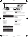
1
KAC-X541
KAC-PS541
4/3/2 CHANNEL POWER AMPLIFIER
INSTRUCTION MANUAL
© B64-2801-00/00 (MV)
2.KAC-X541_M_1US.indd 1
04.1.9, 2:14 PM
Safety precautions
Cleaning the unit
2WARNING
If the front panel gets dirty, turn off the power and wipe the panel with a dry
silicon cloth or soft cloth.
To prevent injury or fire, take the following precautions:
• When extending the ignition, battery, or ground wires, make sure to use
automotive-grade wires or other wires with a 8 mm² (AWG 8) or more to
prevent wire deterioration and damage to the wire coating.
• To prevent a short circuit, never put or leave any metallic objects (such as
coins or metal tools) inside the unit.
• If the unit starts to emit smoke or strange smells, turn off the power
immediately and consult your Kenwood dealer.
• Do not touch the unit during use because the surface of the unit becomes
hot and may cause burns if touched.
2CAUTION
Do not wipe the panel with a hard cloth or a cloth dampened by volatile
solvents such as paint thinner and alcohol. They can scratch the surface of the
panel and/or cause the indicator letters to peel off.
To prevent battery rise
When the unit is used in the ACC ON position without turning the engine ON, it
depletes the battery. Use it after starting the engine.
Protection function
2CAUTION
There is a Protection function installed in the unit to protect the unit and
speakers from various problems. When Protection operates, the display informs
you of the condition.
To prevent damage to the machine, take the following
precautions:
Display
"E-01"
• Be sure the unit is connected to a 12V DC power supply with a negative
ground connection.
• Do not open the top or bottom covers of the unit.
• Do not install the unit in a spot exposed to direct sunlight or excessive heat
or humidity. Also avoid places with too much dust or the possibility of water
splashing.
• When replacing a fuse, only use a new one with the prescribed rating. Using a
fuse with the wrong rating may cause your unit to malfunction.
• To prevent a short circuit when replacing a fuse, first disconnect the wiring
harness.
Informations
When the inside of the unit is overheating.
When the unit has failed and direct current voltage is generated to the speaker’s
output.
"E-02"
NOTE
Turn the power OFF and release the protection. If the "E-02" code does not disappear,
contact your Kenwood dealer.
When the speaker cord is shorted.
When the speaker output is in contact with the vehicle ground.
"E-03"
"VOLT" display is
blinked.
Available Control Units:
A KENWOOD’s LX-Bus supporting Center Unit released in 2004 or later can
control this unit. The operations of the (LX) AMP Control are explained in the
Operation Manual of the Center Unit.
When voltage gets out of operation range.
Wiring
• Take the battery wire for this unit directly from the battery. If it’s connected to
the vehicle’s wiring harness, it can cause blown fuses etc.
• If a buzzing noise is heard from the speakers when the engine is running,
connect a line noise filter (optional) to each of the battery wire.
• Do not allow the wire to directly contact the edge of the iron plate by using
Grommets.
• Connect the ground wire to a metal part of the car chassis that acts as an
electrical ground passing electricity to the battery‘s negative - terminal. Do
not turn the power on if the ground wire is not connected.
• Be sure to install a protective fuse in the power cord near the battery. The
protective fuse should be the same capacity as the unit’s fuse capacity or
somewhat larger.
• For the power cord and ground, use a vehicle type (fireproof ) power wring
cord with a current capacity greater than the unit’s fuse capacity. (Use a power
wiring cord with a diameter of 8 mm² (AWG 8) or greater.)
• When more than one power amplifier are going to be used, use a power
supply wiring wire and protective fuse of greater current-handling capacity
than the total maximum current drawn by each amplifier.
NOTE
• The LX AMP and the sensor unit cannot be connected simultaneously. You
must connect any of them at a time.
NOTE
• If you experience problems during installation, consult your Kenwood dealer.
• If the unit does not seem to be working right, consult your Kenwood dealer.
Speaker Selection
• The rated input power of the speakers that are going to be connected should
be greater than the maximum output power (in Watts) of the amplifier. Use of
speakers having input power ratings that are less than the output power of
the amplifier will cause smoke to be emitted as well as damage.
• The impedance of the speakers that are going to be connected should be 2Ω
or greater (for stereo connections), or 4Ω or greater (for bridged connections).
When more than one set of speakers are going to be used, calculate the
combined impedance of the speakers and then connect suitable speakers to
the amplifier.
4Ω
4Ω
4Ω
4Ω
4Ω
4Ω
2Ω
8Ω
Combined impedance
4Ω
2
4Ω
4Ω
4Ω
4Ω
4Ω
4Ω
4Ω
8Ω
2Ω
English
2.KAC-X541_M_1US.indd 2
04.1.9, 2:14 PM
4Ω
4Ω
4Ω
4Ω
4Ω
4Ω
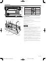
Installation
Accessories
��� ��
��� ��
���
������������ ����� ���������
�
��
���
��
��
���
���
���
���
���
�
�
���
��
���
���
�
�
������
���
�������������
��
��� ��
�
�
���
�
�
������
���
�������� ��
�����
��������������
���
���
�������������
���
���
��������
��� ��
����
Number of Items
4
4
Cover
1
Terminal cover (Power terminal)
1
Hexagon Wrench
1
�����
��������������
� ��
� ��
��� ��
��� ��
��� ��
�� ��
�� ��
�
��
����
���
���
��
��� ���������
��
����
��
���
�������������
��� ���������
���
��� ��
Part name
External View
Self-tapping screws
(ø5 × 18 mm)
Hexagon socket head cap screw
(M4 × 8 mm)
���������
���
���������
������
��� ����
���
���
��
��
���������
��
���������
���
���
������
���
������
���
���
�� �� ��� ��� ��� �� ����
���
�� �� ��� ��� ��� �� ����
���
��
Installation procedure
Duct
Hexagon socket
head cap screw
(M4 × 8 mm)
Hexagon Wrench
Cooling fan
Since there are large variety of settings and connections possible according to
applications, read the instruction manual well to select the proper setting and
connection.
1. Remove the ignition key and disconnect the negative - terminal of the
battery to prevent short circuits.
2. Set the unit according to the intended usage.
3. Connect the input and output wires of the units.
4. Connect the speaker wires.
5. Connect the power wire, power control wire and grounding wire following this
order.
6. Install the installation fittings in the unit.
7. Attach the unit.
8. Install the terminal cover.
9. Connect the negative - terminal of the battery.
2CAUTION
Cooling fan
Cover
Installation board, etc.
(thickness : 15 mm or more)
Self-tapping screw
(ø5 × 18 mm)
• Do not install in the below locations;
(Unstable location, In a location that interferes with driving, In a location
that gets wet, In a dusty location, In a place that gets hot, In a place that
gets direct sunlight, In a location that gets hit by hot air)
• Do not install the unit under the carpet. Otherwise heat build-up occurs
and the unit may be damaged.
• Install this unit in a location which allows heat to easily dissipate.
Once installed, do not place any object on top of the unit.
• The surface temperature of the amplifier will become hot during use. Install
the amplifier in a place where people, resins, and other substances that are
sensitive to heat will not come into contact with it.
• This unit has cooling fans to decrease the internal temperature. Do not
mount the unit in a place where the cooling fan and ducts of the unit are
blocked. Blocking these openings will inhibit the cooling of the internal
temperature and result in malfunction.
• When making a hole under a seat, inside the trunk, or somewhere else in
the vehicle, check that there is nothing hazardous on the opposite side
such as a gasoline tank, brake pipe, or wiring harness, and be careful not to
cause scratches or other damage.
• Do not install near the dashboard, rear tray, or air bag safety parts.
• The installation to the vehicle should securely fasten the unit to a place in
which it will not obstruct driving. If the unit comes off due to a shock and
hits a person or safety part, it may cause injury or an accident.
• After installing the unit, check to make sure that electrical equipment
such as the brake lamps, turn signal lamps and windshield wipers operate
normally.
English
2.KAC-X541_M_1US.indd 3
04.1.9, 2:15 PM
3
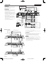
Connection
* Commercially available parts
2WARNING
RCA cable*
CENTER UNIT
(CD receiver, etc.)
To prevent fire caused by a short in the wiring,
connect a fusible link or breaker nearby the
battery’s positive terminal.
RCA cable ground
terminal
Lead terminal*
2CAUTION
Power control wire
A channel
input
�
��
��
��
��
���
��
����� ��
�����������
���
• If sound is not output normally, immediately
turn power off and check connections.
• Be sure to turn the power off before changing
the setting of any switch.
• If the fuse blows, check wires for shorts, then
replace the fuse with one of the same rating.
• Check that no unconnected wires or connectors
are touching the car body. Do not remove
caps from unconnected wires or connectors to
prevent short circuits.
• Connect the speaker wires to appropriate
speaker connectors separately. Sharing the
negative wire of the speaker or grounding
speaker wires to the metal body of the car can
cause this unit to fail.
• After installation, check that the brake lamps,
winkers, and wipers work properly.
B channel
input
�� ������
�� ���
������
�����
A channel
Right speaker
A channel
Left speaker
Terminal cover
B channel
Right speaker
Battery wire*
B channel
Left speaker
Protective Fuse*
Bridged Connections
A channel
Speaker (Bridged)
Battery
Ground wire*
B channel
Speaker (Bridged)
LX-Bus connection
To KENWOOD disc changer/
External optional accessory
CENTER UNIT
Set the ID number of the Master amplifier to "0".
You can connect up to 7 Slave amplifiers. Assign them ID numbers "1"
to "7" and do not duplicate them.
2CAUTION
Control cable
(option)
Power control wire
• Do not connect 2 Master amplifiers to the Center Unit. If done, you
cannot control all amplifiers connected to the Center Unit.
• The LX AMP and the sensor unit cannot be connected
simultaneously. You must connect any of them at a time.
NOTE
��
��
• The total length of S-video cables you can connect is 14 meters
(46 ft) maximum. If the cable length exceeds this limit, you cannot
control amps from the Center Unit.
• If you assign the same ID number to multiple amplifiers, they
malfunction when you operate any of them from the Center Unit.
• If you assign ID number "8" or "9" to a Slave amplifier, it is not
recognized by the Center Unit.
��
��
����� ��
�� ������
������
�����
��
��
���
Master amplifier
�� ���
���
���
�����������
���
���
�� ������
S-video cable*
Extension wire*
RCA cable*
��
��
��
��
����� ��
�� ������
������
�����
��
���
��� � ���
�� ���
���
��
Slave amplifier 1
���
���
�����������
�� ������
Not more than
14m (46 ft)
��
��
��
��
�� ������
������
�����
��
���
��� � ���
�� ���
���
��
Slave amplifier 7
����� ��
���
���
�����������
�� ������
4
English
2.KAC-X541_M_1US.indd 4
04.1.9, 2:15 PM
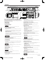
Controls
����
����
����
��
��
���
��
��
���
� ��
����� ��
�����������
�
�
�
�� ������
�
�
�� ���
� �
������
�
�
��
���
�������������
��� ���������
�
��
��
��
���
���
���
���
�� �� ��� ��� ��� �� ����
���
���
�������������
��
�����
��������������
���
�
�
������
���
���
�������������
���
��������
�����
��������������
� ��
������
��� ����
���
���
��
��
���������
���������
���
��
���������
���������
���
���
������
���
������
���
���
�� �� ��� ��� ��� �� ����
� �
� � �
�
�
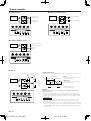
This is a 4 channel amplifier including 2 stereo amplifiers in a body. One
amplifier is referred to as amplifier A and the other is amplifier B. This unit
is compatible with a large variety of systems by combining the switches and
functions described in the following.
# Power indicator
1 Fuse (30 A × 2)
2 Battery terminal
3 Ground terminal
4 Power control terminal
$ HPF FREQUENCY control (A.ch/B.ch)
When you wish to use the unit as a stereo amplifier, stereo connections are
used.
The speakers to be connected should have an impedance of 2Ω or greater.
When multiple speakers are to be connected, ensure that the combined
impedance is 2Ω or greater for each channel.
• Bridged Connections:
When you wish to use the unit as a high-output monaural amplifier,
bridged connections are used. (Make connections to the LEFT channel 9
and the RIGHT channel · SPEAKER OUTPUT terminals.)
The speakers to be connected should have an impedance of 4Ω or greater.
When multiple speakers are to be connected, ensure that the combined
impedance is 4Ω or greater.
2CAUTION
The rated input of the speakers should be no less than the maximum output
of the amplifier. Otherwise malfunction may result.
6 RCA cable ground lead terminal
When using an RCA cable with a ground lead attached, connect the ground
lead to this terminal.
7 ID NUMBER switch
Sets an amp identification number (ID) to be used for amplifier control from
the Center Unit.
Assign ID Number "0" to an amplifier when you use it as the Master amplifier.
Assign ID Numbers "1" to "7" to amplifiers when you use them as Slave
amplifiers. Do not duplicate these numbers.
NOTE
After you have changed ID numbers of amplifiers, turn Off the POWER switch
of the Center Unit and turn it On again.
8 TO H/U terminal
After you have set the Master amplifier, connect it to the Center Unit.
9 REMOTE terminals
Used to connect to Slave amplifiers.
0 RESET button
Resets the microprocessor of the unit.
NOTE
The values you have set with the Amplifier Control are NOT reset.
! LINE IN terminal (A.ch/B.ch)
@ LINE OUT terminal
These jacks output respectively the signals input to amplifiers A and B.
They always output the stereo signals regardless of the position of the
OPERATION switch.
���
����
����
����
A: Sets the cutoff frequency when the "HPF" switch is set to "ON".
B: Sets the cutoff frequency when the "FILTER" switch is set to "HPF".
% LPF FREQUENCY control (B.ch)
Sets the cutoff frequency when the "FILTER" switch is set to "LPF".
���
���
���
��
^ FILTER switch (B.ch)
��
���
�������������
��
���
���
���
���
�
���
���
�
�
������
���
�������������
��
�
�����
��������������
�
���
���
�
�
������
���
�������� ��
���
���
�������������
���
��������
�����
��������������
This switch allows to apply high-pass or low-pass filtering to the speaker
outputs.
��� ���������
�
��
��
���
�
���
��
NOTE
5 Speaker output terminals (A.ch/B.ch)
• Stereo Connections:
��
Lights when the POWER switch is turned On.
The indicator flashes several seconds when the POWER switch is turned On
or when the Protection function is activated.
Controls the unit ON/OFF.
Controls the unit power. Be sure to connect it with all the systems.
�
�
�
���
���
�������� ��
� ��
��� ��
��� ��
��� ��
�� ��
�� ��
�
���
�
�
������
�
���
�
���
��� ���������
�
��
���
��
���
�
���
��
��
�
���
���
���
�����
� ��
��� ���������
��� ��
��� ��
��� ��
�� ��
�� ��
�
��
��
� ��
������
��� ����
���
���
��
��
���������
���������
���
���������
��
• HPF (High-Pass Filter) position:
���
���������
���
���
�� �� ��� ��� ��� �� ����
���
�� �� ��� ��� ��� �� ����
���
���
���
������
���
������
The filter outputs the band of higher frequencies than the frequency set
with the "HPF FREQUENCY" control.
• OFF position:
The entire bandwidth is output without filtering.
• LPF (Low-Pass Filter) position:
The filter outputs the band of lower frequencies than the frequency set
with the "LPF FREQUENCY" control.
The speaker output is automatically switched to monaural (L+R).
& AMP CONT (amplifier control) switch (B.ch)
Used to bypass the circuit when you do not control the sound with the
Amplifier Control.
• ON position:
You can control the sound of amplifier B using the Amplifier Control.
• OFF position:
Bypasses the Amplifier Control circuit.
NOTE
Amplifier control is possible even while OFF.
* ISF (infrasonic filter) switch (B.ch)
When this switch is "ON", the frequencies which are below the audible
range and therefore inaudible are cut off so that the quality of the audible
frequencies can be improved.
( OPERATION switch (A.ch/B.ch)
The amplification methods of the signals input to amplifiers A and B can be
selected independently according to the setting of this switch.
• STEREO position:
The amplifier can be used as a stereo amplifier.
• MONO (Lch) position:
Amplifies the signal input from the left side only. Set to this position and
make bridged connections to use as a high-power monaural amplifier. (The
input right signal is not output.)
) HPF (High-Pass Filter) switch (A.ch)
This switch allows to apply high-pass filtering to the speaker outputs.
• ON position:
The filter outputs the band of higher frequencies than the frequency set
with the "HPF FREQUENCY" control.
• OFF position:
The entire bandwidth is output without filtering.
@1 INPUT SENSITIVITY control (A.ch/B.ch)
Set this control according to the pre-output level of the center unit
connected with this unit.
NOTE
For the pre-output level, refer to the "Specifications" in the instruction manual
of the center unit.
English
2.KAC-X541_M_1US.indd 5
04.1.9, 2:15 PM
5
Amplifier Control System
Indicator
���
����
����
����
MENU
2/3
���
���
���
��
��
��
���
���
�������������
��� ���������
�
��
��
��
���
���
���
���
���
Display mode
�� �� ��� ��� ��� �� ����
���
���
�������������
��
�
�����
��������������
�
���
�
�
������
���
�������� ��
���
���
�������������
� ��
��� ��
��� ��
��� ��
�� ��
�� ��
�� �� ��� ��� ��� �� ����
���
�
�
������
���
���
��������
�����
��������������
� ��
������
��� ����
���
���
��
��
���������
���������
���
��
���������
���������
���
���
������
���
������
���
���
4 Exit Menu mode
You can set up the display items as follows:
1 Enter Menu mode
Press the [MENU] button.
"VOLT"/"CURR"/"TEMP"/"FAN" is displayed.
2 Select a display item
Press the [2] or [3] button.
The display items are switched in the following sequence.
Display
"VOLT"
"CURR"
"TEMP"
"FAN"
���
��� ���������
�
��
���
�
�
���
��
Information
Indicates the source voltage (V).
Indicates the current consumption (A).
Indicates the internal temperature (°F/°C).
Indicates the rotation speed of the cooling fan in 3 steps: "FAST", "SLOW" or "OFF".
Press the [MENU] button for at least 1 second.
NOTE
When you hold down the [3] button 3 or more seconds during ID number
display ("AMP"), message "MEMO" is displayed and you can register the values
you have set with the Amplifier Control. To call the Amplifier Control’s values,
hold down the [2] button 3 or more seconds during ID number display
("AMP"). Then, you can recall the value when message "LOAD" is displayed.
Default
Resets all values you have set to the initial (default) values.
1 Enter Menu mode
Press the [MENU] button.
2 Select Default mode
3 Exit Menu mode
Press the [MENU] button for at least 1 second.
NOTE
When the internal temperature is -22°F/-30°C or less, "-22F"/"-30C" is
displayed.
Press the [MENU] button.
Select the "DEFA" display.
3 Resets the value to its default
Press the [3] button for at least 2 seconds.
Message "----" is displayed, and the value is initialized.
4 Exit Menu mode
Separate Amp Control
Press the [MENU] button for at least 1 second.
The following explains how to control the sound of amplifier B using the
Amplifier Control of the unit.
NOTE
Volume offset value can not be initialized.
1 Enter Menu mode
Press the [MENU] button.
Display Demonstration
2 Select the Menu item
Press the [MENU] button.
The setup items are displayed approximately 1 second first, then the set
values are displayed.
3 Adjust the Menu item
Press the [2] or [3] button.
The setup items and set values are switched as follows.
Display Range
"VOLT"/"CURR"/"TEMP"/"FAN"
"BASS" 60/80/100/200 (Hz)
"BA G"
B–15 — B+15 (dB)
"BA Q"
Q1.00/Q1.25/Q1.50/Q2.00
" EXT"
ON/OFF
"TREB"
"TR G"
"VOL"
10/12/15/17 (kHz)
T–15 — T+15 (dB)
–20 — 0 (dB)
FAHR (Fahrenheit) or
CELS (Centigrade)
"TEMP"
"DEFA"
"AMP"
6
0—7
The "VOLT"/"CURR"/"TEMP"/"FAN" items are displayed repeatedly.
Press the [MENU] button for at least 2 seconds.
The indicator flashes in the Demonstration mode.
Canceling the Demonstration mode
Press any button to cancel the Demonstration mode.
Adjustment Item
For the operation method refer to 'Display mode'
Bass Center Frequency
Bass level
Bass Q Factor
When the bass extend is set to ON, low frequency response is
extended by 20%.
Treble Center Frequency
Treble level
Volume offset
The Fahrenheit or Centigrade temperature unit can be selected
for the Display mode.
For the operation method refer to 'Default'
The ID Number you have assigned is displayed.
English
2.KAC-X541_M_1US.indd 6
04.1.9, 2:15 PM
Control an Amp from Center Unit
Messages that may be displayed on the Center Unit
The following explains how to control the sound of Amplifier B by operating
the Amplifier Control of the unit from the Center Unit.
When you are selecting an item with the Amp Control, an error status of the
amplifier is displayed on the Center Unit.
1 Enter AMP Control mode
Select the AMP Control mode by following the 'AMP Control' procedure
given on the Operation Manual of the Center Unit.
NOTE
Use the set item and value operation buttons by following the instructions
given on the Operation Manual of the Center Unit.
2 Select an amp number to operate
Operate the desired set item with the Center Unit.
Select the "AMP NO"/"AMP CONTROL NO" display.
NOTE
When the Center Unit is in the STANDBY mode, message "AMP OFF" is
displayed and you cannot operate the set items.
Display
Informations
"AMP × E-01"/"AMP × COND E-01" When the inside of the unit is overheating.
When the unit has failed and direct current voltage is generated
to the speaker’s output.
"AMP × E-02"/"AMP × COND E-02"
NOTE
Turn the POWER switch Off and release the protection. If the
error message continues, consult to the KENWOOD’s dealership.
"AMP × E-03"/"AMP × COND E-03"
"AMP OFF"
When the speaker cord is shorted.
When the speaker output is in contact with the vehicle ground.
When you use the Amp Control in the Standby mode.
NOTE
Number "×" on the display indicates the amp’s ID number.
3 Set an ID number of Amp to operate
Set an amp’s ID number on the Center Unit.
You can select an ID number of "0" to "7" of connected amps.
4 Select the AMP Control item for adjustment
Select the desired set item on the Center Unit.
5 Adjust the AMP Control item
You can set a value of each item on the Center Unit.
The set items and their values are switched and displayed as follows.
Display
Range
"VOLT"/"CURR"/"TEMP"/"FAN"
"VOLT"
"CURR"
"TEMP"
"FAN"
"BAS F"/"BASS FREQ"
"BAS G"/"BASS GAIN"
"Q FA"/"Q FACTOR"
"EXT"/"BASS EXT"
"TRE F"/"TREB FREQ"
"TRE G"/"TREB GAIN"
"VOL"/"VOL OFFSET"
"AMP NO"/
"AMP CONTROL NO"
Adjustment Item
The amp state is displayed.
Indicates the source voltage (V).
Indicates the current consumption (A).
Indicates the internal temperature (°F/°C).
Indicates the rotation speed of the cooling fan in
3 steps: "FAST", "SLOW" or "OFF".
60/80/100/200 (Hz)
Bass Center Frequency
–15 — +15 (dB)
Bass level
Q1.00/Q1.25/Q1.50/Q2.00 Bass Q Factor
ON/OFF
When the bass extend is set to ON, low frequency
response is extended by 20%.
10/12/15/17 (kHz)
Treble Center Frequency
–15 — +15 (dB)
Treble level
–20 — 0 (dB)
Volume offset
0—7
Select an ID number of the amp you use.
6 Exit AMP Control mode
Releases the Amp Control mode by the Center Unit.
NOTE
When you have controlled the bass or treble of the sound using the
Equalizer or DSP function of the Center Unit, and when you amplify the same
frequency as that controlled by the Amplifier Control, the sound may be
distorted due to an input overflow.
English
2.KAC-X541_M_1US.indd 7
04.1.9, 2:15 PM
7
System examples
4-channel system
High-power 2-channel system
CENTER UNIT
���
���
���
Rear Left speaker
��
��
���
���
�������������
�
���
���
�
�
������
���
���
�������������
� ��
���
�
�
������
���
���
�
���
���
�����
��������������
���
�������������
�
��
�������� ��
�
Rear Right speaker
���
�
��
CENTER UNIT
Front Right speaker
�
�
�
�
�
��
�
Front Left speaker
�
�
�
�
�
���
���
��
��
��������
��
���
���
�������������
�����
��������������
��� ����
���
���
��
��
���������
��
���������
Right speaker (Bridged)
���
���
�������������
��
�
�������� ��
�����
��������������
�
���
���
�
�
������
���
���
���
�������������
� ��
���
���������
�
�
�
�
�
���
�
�
������
���
� ��
������
Left speaker (Bridged)
�
�
���
��
���
�
�
�
�
�
���
��������
�����
��������������
� ��
������
��� ����
���
���
��
��
���������
��
���������
���
���
������
���
������
���������
���������
���
���������
���
���
���
���
���
���
������
���
������
2-channel + Subwoofer system
CENTER UNIT
���
���
���
��
���
�������������
�
���
��
���
Right speaker (High pass)
�
�
�
�
�
Subwoofer
(Bridged)
���
�
��
���
�
�
������
��
���
�
��
�
���
�������� ��
���
���
�������������
� ��
���
�
�
������
���
�����
��������������
���
�������������
Left speaker (High pass)
�
�
�
�
�
���
��������
�����
��������������
� ��
������
��� ����
���
���
��
��
���������
��
���������
���
���
������
���
������
���
���������
���������
���
���
Tri-mode
Subwoofer
(L + R) (Bridged)
(High pass)
�
�
CENTER UNIT
�
�
�
�
Principle of Tri-mode
Method of frequency band division using a coil and capacitor…in case of 6dB/oct. slope.
Crossover Frequency
0 dB
-3 dB
�
�
L
�
�
�
�
�
�
Frequency
159 x R
L=
(mH)
fc
�
�
C
Coil (L):
Passes low frequencies and blocks high
frequencies. (Low pass)
Capacitor (C):
Passes high frequencies and blocks low
frequencies. (High pass)
C=
159000
(µF)
fc × R
fc=Cut of Frequency (Hz)
R=Speaker Impedance (Ω)
Example:
���
���
���
��
���
��
��
���
���
�������������
��
���
�
�
���
���
�
�
������
���
�������������
�
��
���
�
�
������
���
�������� ��
�����
��������������
�
���
���
�������������
� ��
���
���
��������
�����
��������������
� ��
������
��� ����
���
���
��
��
���������
���������
���
��
���������
���������
���
���
8
���
���
������
���
When it is required to set a crossover frequency of 120 Hz using speakers with an
impedance of 4 ohms.
Prepare commercially-available coil and capacitor with the closest ratings to the
results calculated from the formula above. The capacitor rating should be as close as
possible to 331.25 (µF) and the coil rating should be as close as possible to 5.3 (mH).
������
2CAUTION
• If you wish to bridge-connect a speaker, the speaker impedance must be no less
than 4 ohms. Connecting a speaker with an impedance lower than 4 ohms may
damage the unit.
• Be sure to connect capacitors to speakers to which high frequencies will be passed.
Failure to do so will result in a drop of the combined impedance with the subwoofer.
• Ensure that the withstand voltage and current ratings of the capacitors (C) and coils
(L) are sufficient.
English
2.KAC-X541_M_1US.indd 8
04.1.9, 2:15 PM
Troubleshooting Guide
What might appear to be a malfunction in your unit may just be the result of slight misoperation or miswiring. Before calling service, first check the following
table for possible problems.
PROBLEM
POSSIBLE CAUSE
SOLUTION
No sound.
(No sound from one side.)
(Blown fuse.)
•
•
•
•
•
•
•
•
The output level is too small
(or too large).
The sound quality is bad.
(The sound is distorted.)
• The input sensitivity adjusting control is not set to the correct
position.
• The speakers wire are connected with wrong + /-polarity.
•
The sound does not change
even when you have changed
it with the Amplifier Control.
The set value cannot be
changed by the Amplifier
Control of the unit.
The Amplifier Control cannot
be operated from the Center
Unit.
•
•
•
Input (or output) cables are disconnected.
Protection circuit may be activated.
Volume is too high.
The speaker cord is shorted.
Connect the input (or output) cables.
Check connections by referring to "Protection function".
Replace the fuse and use lower volume.
After check the speaker cord and fixing the cause of the short,
replace the fuse.
• Adjust the control correctly referring to "Controls".
• Connect them properly checking the + / - of the terminals
and wires well.
A speaker wire is pinched by a screw in the car body.
• Connect the speaker wire again so that it is not pinched by
anything.
The switches may be set improperly.
• Set switches properly by referring to "System examples".
The AMP CONT has been turned "OFF".
• Turn the AMP CONT "ON".
The filtered band has been controlled by the Amplifier Control. • Turn the filter Off.
• The AMP Control of the Center Unit is being used.
• Release the AMP Control mode of the Center Unit.
• An incorrect ID number is used for the Master amplifier.
• The ID number of the amplifier has been changed.
• Always set the ID number of the Master amplifier to "0".
• After you have changed the ID number of an amplifier, turn Off
the POWER switch of the Center Unit first, then turn it On again.
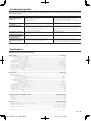
Specifications
Specifications subject to change without notice.
Audio Section............................................................................................................................................ KAC-X541
RMS Power Output (+B = 14.4 V, CEA-2006)
Normal (4 Ω/4ch) (1.0 % THD+N)..............................................................................................................................................................................88 W
Normal (2 Ω/4ch) (1.0 % THD+N)........................................................................................................................................................................... 124 W
Bridged (4 Ω/2ch) (1.0 % THD+N)..................................................................................................................................................................270 W × 2
Dynamic Power (+B = 14.4 V, CEA-2006) .......................................................................................................................................................................... 100 W
Output Regulation (+B = 14.4 V, CEA-2006)..........................................................................................................................................under 0.3 dB (4 Ω)
Signal to Noise Ratio (CEA-2006)...................................................................................................................................................................... 76 dBA (W/4 Ω)
Signal to Noise Ratio (Bypass) (CEA-2006) .................................................................................................................................................. 76 dBA (W/4 Ω)
Low Pass Filter Frequency (24 dB/oct.) (B channel) .................................................................................................................. 50 – 200 Hz (variable)
High Pass Filter Frequency (12 dB/oct.)........................................................................................................................................... 50 – 200 Hz (variable)
Infrasonic Filter Frequency (24 dB/oct.) (B channel).................................................................................................................................................... 15 Hz
Frequency Response (+0, –3 dB)...........................................................................................................................................................................5 Hz – 70 kHz
Sensitivity (rated output) (MAX.) ............................................................................................................................................................................................. 0.2 V
Sensitivity (rated output) (MIN.) .............................................................................................................................................................................................. 5.0 V
Input Impedance ............................................................................................................................................................................................................................ 10 kΩ
Audio Section.......................................................................................................................................... KAC-PS541
Max Power Output ....................................................................................................................................................................................................................... 960 W
Rated Power Output (+B = 12.0 V)
Normal (4 Ω) (20 Hz – 20 kHz, 0.05 % THD)................................................................................................................................................ 45 W × 4
Normal (2 Ω) (1 kHz, 0.5 % THD) ....................................................................................................................................................................... 90 W × 4
Bridged (4 Ω) (1 kHz, 0.5 % THD) ....................................................................................................................................................................180 W × 2
Rated Power Output (+B = 14.4 V)
Normal (4 Ω) (20 Hz – 20 kHz, 0.05 % THD)................................................................................................................................................ 60 W × 4
Normal (4 Ω) (DIN : 45324 , +B = 14.4V) ....................................................................................................................................................... 60 W × 4
Normal (2 Ω) (1 kHz, 0.5 % THD) .....................................................................................................................................................................120 W × 4
Bridged (4 Ω) (1 kHz, 0.5 % THD) ....................................................................................................................................................................240 W × 2
Low Pass Filter Frequency (24 dB/oct.) (B channel) .................................................................................................................. 50 – 200 Hz (variable)
High Pass Filter Frequency (12 dB/oct.)........................................................................................................................................... 50 – 200 Hz (variable)
Infrasonic Filter Frequency (24 dB/oct.) (B channel).................................................................................................................................................... 15 Hz
Frequency Response (+0, –3 dB)...........................................................................................................................................................................5 Hz – 70 kHz
Signal to Noise Ratio...................................................................................................................................................................................................................105 dB
Sensitivity (rated output) (MAX.) ............................................................................................................................................................................................. 0.2 V
Sensitivity (rated output) (MIN.) .............................................................................................................................................................................................. 5.0 V
Input Impedance ............................................................................................................................................................................................................................ 10 kΩ
Amplifier Control Section (EQ) (B channel) ................................................................................ KAC-X541/PS541
Bass frequency .............................................................................................................................................................................................. 60 / 80 / 100 / 200 Hz
Bass level ........................................................................................................................................................................................................................... -15 — +15 dB
Bass Q factor.................................................................................................................................................................................................1.00 / 1.25 / 1.50 / 2.00
Treble frequency ............................................................................................................................................................................................. 10 / 12 / 15 / 17 kHz
Treble level ....................................................................................................................................................................................................................... -15 — +15 dB
General .......................................................................................................................................... KAC-X541/PS541
Operating Voltage ........................................................................................................................................................................... 14.4 V (11 – 16 V allowable)
Current Consumption (+B = 12.0 V, 1 kHz, 10 % THD, 4 Ω).........................................................................................................................................42 A
Dimensions (W × H × D) ..........................................................................................................................................................................446 × 61 × 259.5 mm
.............................................................................................................................................................................................. 17-5/8 × 2-3/8 × 10-3/16 inch
Installation Size (W × H × D) ..................................................................................................................................................................... 446 × 61 × 265 mm
................................................................................................................................................................................................. 17-5/8 × 2-3/8 × 10-3/8 inch
Weight .......................................................................................................................................................................................................................... 4.47 kg (9.85 lbs)
English
2.KAC-X541_M_1US.indd 9
04.1.9, 2:15 PM
9
2.KAC-X541_M_1US.indd 10
04.1.9, 2:15 PM